

Sony IPELA PCS-HG90 Connection Setup
S
S
Video Communication System
RGB
AUDIO IN
VIDEO IN
S-VIDEO
Y
12
HD-SDIHD-SDI
SUB
CAMERA
MAIN
CAMERA
Pb Pr
R MIC L R
AUX 2
R
MIC
EC-MIC(A7)
12
A1/A3
(PLUG IN POWER)
1(R) 2(L)
LRL
AUX 1 L
3-991-629-11 (1)
System Setup
3 Camera Unit
PCSA-CHG90***
1 2 3 4 5 6 7 8 9
VISCA RS-232C OUT
VISCA RS-422
HFBK-HD1
MONITOR HD-SDI
* supplied with the Communication Terminal
** supplied with the Camera Unit
*** not supplied
DC IN 12V
to a wall outlet
Connection Sheet
PCS-HG90
2006 Sony Corporation Printed in Japan
“IPELA” and are trademarks of Sony Corporation.
2 Microphones
PCSA-A3***
VISCA cable**
RGB
S-VIDEO
RMICL R
MIC
EC-MIC(A7)12A1/A3
1(R) 2(L)
(PLUG IN POWER)
TV monitor***
1
Y
VIDEO IN
Pb Pr
AUDIO IN
AUX 2
R
BNC cable**
HD-SDI HD-SDIHD-SDI
1
2
SUB
MAIN
CAMERA
CAMERA
AUX 1 L L
LRL
VIDEO OUT
YPbPr
REC OUT(MIXED)AUDIO OUT
RLR
AUX CONTROL
CAMERA CONTROL 100BASE-TX/
CTRL-S
SUB MAIN
YPbPr
(NEAR ONLY)
~ AC IN
10BASE-T
(VISCA)
4 LAN cable***
4 Remote Control
Receiver*
to a wall outlet
Communication
Terminal
PCS-PHG90
5 Power cord*
LAN
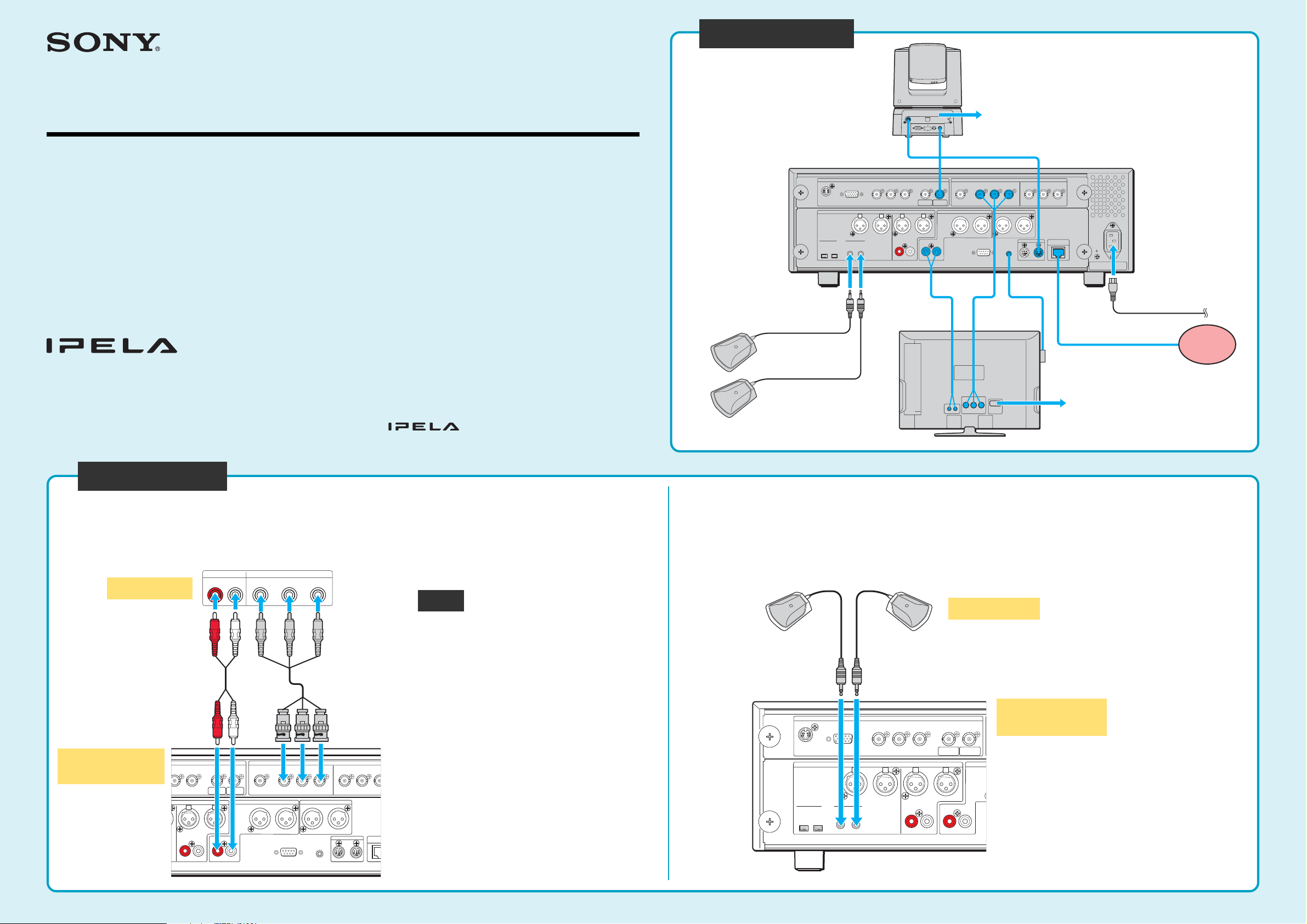
Let’s connect
Connect the TV monitor.
1
Communication
Terminal
*** not supplied
Connect the TV monitor and Communication Terminal using the video cable and
audio cable (not supplied).
TV monitor
Audio cable***
UDIO IN
RL
Pb Pr
R
AUX 2
RL RL
2
SUB
CAMERA
CAMERA
AUX 1 L L
YPbPr
HD-SDI HD-SDIHD-SDI
1
MAIN
VIDEO INAUDI O IN
Video cable***
VIDEO OUT
YPbPr
REC OUT(MIXED)AUDIO OUT
RLR
AUX CONTROL
CTRL-S
YPbPr
(NEAR ONLY)
CAMERA CONTROL 100BA
(VISCA)
SUB MAIN
Connect microphones.
2
Connect the microphone cables to the Communication Terminal.
Right
Notes
• Be sure to turn off all equipment before
making any connections.
• When connecting a TV monitor for local
pictures only, use the VIDEO OUT YPbPr
(NEAR ONLY) connectors on the
Communication Terminal. For details, refer
to the Operating Instructions.
• When connecting a TV monitor equipped
with XLR-type audio input connectors, use
the XLR-type AUDIO OUT connectors on
the Communication Terminal.
• The REC OUT (MIXED) connectors are
10BA
used to make an audio recording of a
conference. These are not used during
regular conferences.
Left
Microphones
Communication
Terminal
If you connect two microphones, you can
pick up the sound of a conference in stereo.

I
AUX CONTROL
CAMERA CONTROL 100BASE-TX/
10BASE-T
(VISCA)
SUB MAIN
CTRL-S
REC OUT(MIXED)AUDIO OUT
RLR
1
VIDEO OUT
YPbPr
(NEAR ONLY)
YPbPr
2
HD-SDI HD-SDIHD-SDI
SUB
CAMERA
MAIN
CAMERA
RL
1L L
VISCA RS-422
1 2 3 4 5 6 7 8 9
VISCA RS-232C OUT
DC IN 12V
HFBK-HD1
MONITOR HD-SDI
C
3
Connect the Camera Unit.
Connect the Camera Unit and Communication Terminal using the BNC cable and
VISCA cable supplied with the Camera Unit.
Camera Unit
AC power adaptor and power cord **
to a wall outlet
Connect the Remote Control Receiver and the
4
LAN cable.
Connect the supplied Remote Control Receiver to the Communication Terminal.
Then, connect the Communication Terminal to a LAN using a LAN cable (not supplied).
Remote Control
Receiver
to LAN
UTP cable
(category 5, straight)***
Communication
Terminal
** supplied with the
Camera Unit
5
Communication
VISCA cable**
BNC cable**
Notes
• You cannot view the picture from the
camera even if you connect the
Camera Unit directly to the TV monitor.
Be sure to connect the TV monitor to
the Communication Terminal.
• Do not connect/disconnect the BNC
cable or VISCA cable with the power
on. Doing so may damage the Camera
Unit or Communication Terminal.
Connect the power cord.
Connect the supplied power cord to the Communication Terminal, and then to a wall outlet.
VIDEO OUT
Terminal
YPbPr
O OUT
L
REC OUT(MIXED)
RL
YPbPr
(NEAR ONLY)
The Remote Control Receiver receives
VIDEO OUT
Pb Pr
YPbPr
signals from the supplied Remote
Commander. To use the Remote
Commander, point it to the Remote Control
Receiver.
The Remote Control Receiver can be fixed
to a TV monitor, etc. using Velcro.
Note
L
ONTROL
REC OUT(MIXED)
RL
CTRL-S
(NEAR ONLY)
CAMERA CONTROL 100BASE-TX/
(VISCA)
SUB MAIN
~ AC IN
10BASE-T
For safety reasons, do not connect the
100BASE-TX/10BASE-T connector to a
network that applies an excess voltage via
*** not supplied
Communication
Terminal
the 100BASE-TX/10BASE-T connector.
If No Picture Appears on the TV Monitor
The video format of the Communication Terminal is set to “1080/60i” at the factory.
If the video format set on the TV monitor is different from that on the Communication Terminal, no
picture appears on the TV monitor.
Check the video format setting on the TV monitor, and, if necessary, change the video format setting
on the Communication Terminal.
To change the video format on the Communication Terminal
Use the FAR/NEAR button and number buttons 1, 2 and 3 on the supplied Remote Commander.
* supplied with the Communication Terminal
AUX CONTROL
CAMERA CONTROL 100BASE-TX/
CTRL-S
SUB MAIN
(VISCA)
10BASE-T
Power cord*
~ AC IN
to a wall outlet
(100 – 240V AC)
DISPLAY
CLEAR SYMBOL
PinP
BACK
SPACE
RETURN
VIDEO INPUT
PUSH
ENTER
CONNECT/
DISCONNECT
FAR/NEAR
ALPHA/
NUM
MENU
FAR/NEAR
button
Number buttons
1, 2, 3
Video format
to be set
Operation
1080/60i Press “FAR/NEAR”, then press “1” three times.
1080/50i Press “FAR/NEAR”, then press “2” three times.
720/60p Press “FAR/NEAR”, then press “ 3” three times.
Note
The video format of the signal output from the VIDEO OUT
(NEAR ONLY) connectors is fixed to “720/60p”. Use a TV
monitor that supports “720/60p” for the monitor exclusively
for local pictures.
 Loading...