

Sony IPELA PCS-G50, IPELA PCS-G50P, IPELA PCS-G70, IPELA PCS-G70P Technical Documentation Manual
Page 1

VIDEO COMMUNICATION SYSTEM-TECHNICAL DOCUMENTATION
Integration with
Sony Network Camera
PCS-G50/G50P Ver. 2.61 or later
PCS-G70/G70P Ver. 2.61 or later
Page 2
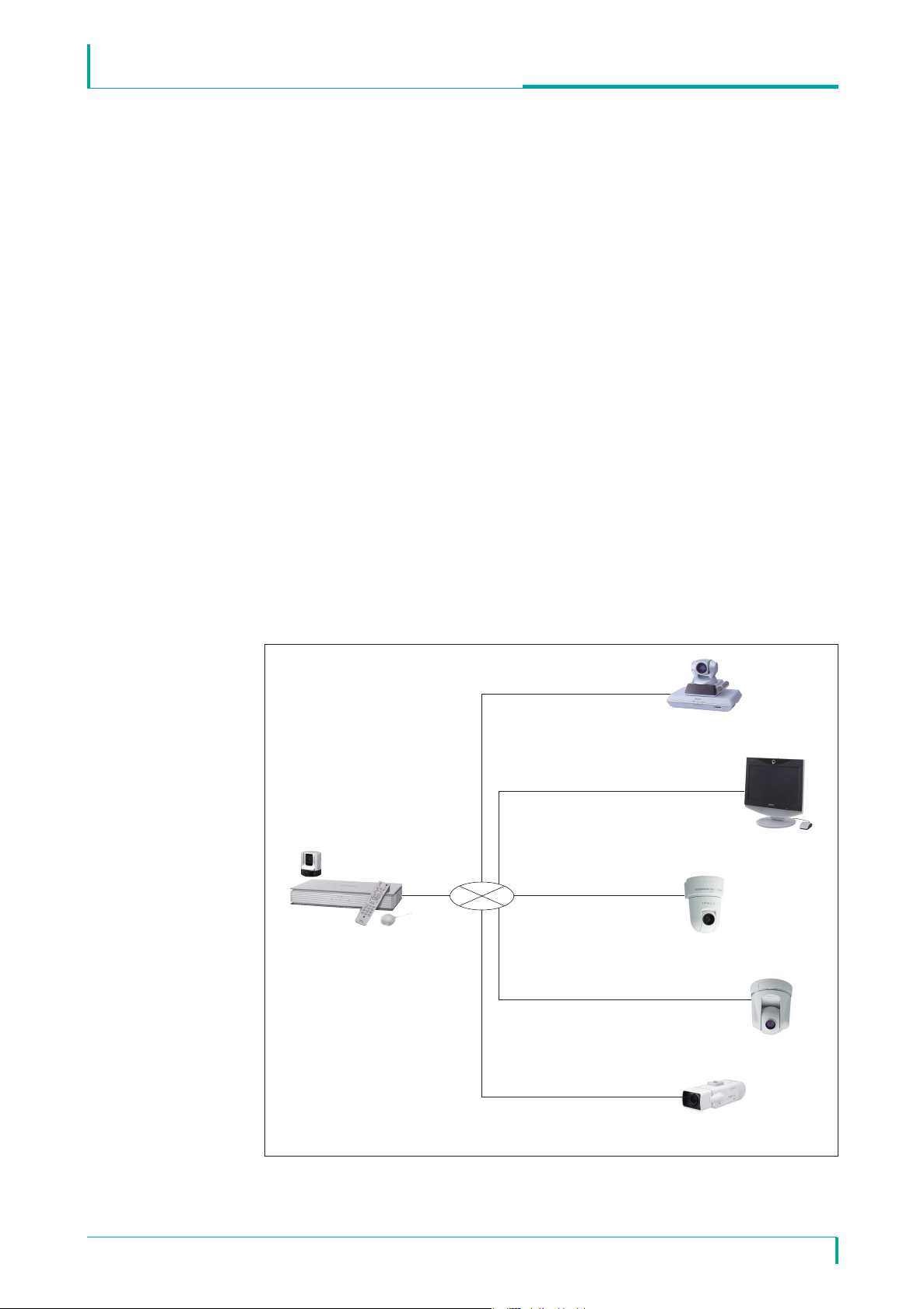
Integration with Sony Network Camera
Main Terminal
PCS-G50/G70
SNC-RZ50N/RZ50P
SNC-CS50N/CS50P
SNC-RX550N/RX550P
ISDN (H.320)
Sub-terminal
Sub-terminal
IP (H.323/SIP)
IP, UDP (Unicast) transmission
IP, UDP (Multicast) transmission
IP, TCP transmission
Introduction
The Sony Visual Communication System PCS-G50/G70 is the first in the industry
with features that allow connection with network cameras. These features allow
you to connect to Sony network cameras as if you were calling a videoconference
partner. In addition to viewing network camera images through the PCS-G50/G70,
audio exchange is also possible between the PCS-G50/G70 and the network
cameras, and pan, tilt and zoom operations can be performed on network cameras
through the PCS-G50/G70. Furthermore, the cameras can be used to conduct
multipoint conferences with a mixture of connections, such as IP and ISDN.
These integration features expand the potential of new applications beyond
conventional videoconferencing.
This document describes the network camera integration features supported by the
PCS-G50/G70.
* In this document, PCS-G50/G70 refers to both the NTSC PCS-G50/G70 and PAL PCS-G50P/G70P models.
VIDEO COMMUNICATION SYSTEM-TECHNICAL DOCUMENTATION
Connection Example
February, 2008 / Ver 1.0©2008 Sony Corporation
2
Page 3

Integration with Sony Network Camera
Main Features
Video/Audio Types
H.264 and MPEG4 are supported for video (for single codec only).
G.711 is supported for audio.
You can monitor real-time network camera images and transmit voice data bidirectionally through the PCS-G50/G70 during a videoconference.
Easy Connection
Through the phone book (called the “network camera list”) of the PCS-G50/G70,
you can easily connect to a network camera using a procedure similar to that for
videoconferencing. You can register up to 20 network cameras in the network
camera list.
• The network camera list is separate from the 500 items in the ordinary phone
book.
• Private and shared phone books are not supported.
• To register a network camera in the network camera list, see the PCS-G50/G70
Operating Instructions Manual (Version 2.6).
VIDEO COMMUNICATION SYSTEM-TECHNICAL DOCUMENTATION
Multipoint Connection
Up to 6 points (including the local site) can be connected, and split-screen viewing is
possible. Multipoint connection in a mixed IP (H.323/SIP) and ISDN environment is
possible for video communication terminals.
• For multipoint connection, MCU software for LAN connection (sold separately)
is required.
• For multipoint connection in a mixed SIP and ISDN environment, SIP software
and MCU software for ISDN connection (sold separately) are required.
Far End Camera Control
You can use the far end camera control function when connected to a network
camera. The procedures for acquiring broadcast permission for the target network
camera and for controlling the far end camera are the same as for when the
PCS-G50/G70 is used at a remote site.
• To use the far end camera control function, you must have the proper permission
settings. (See p.5.)
• If the far end camera control function is enabled by the PCS-G50/G70, it can
also be used from video communication terminals as sub-terminals.
• The far end camera control function can be used in full screen display mode
only.
February, 2008 / Ver 1.0©2008 Sony Corporation
3
Page 4

Integration with Sony Network Camera
Preset Function
You can use the preset function (from 1 to 6 preset positions) for the network
camera connection. You can also register preset positions through the
PCS-G50/G70. The procedures for registering and calling up the presets are the
same as for when the PCS-G50/G70 is used at a remote site.
• To use the preset function, you must have the proper permission settings.
(See p.5.)
Status Indication
As with the videoconferencing connection, you can use the Status menu for the
network camera connection to check the communication status during
communication, as well as the previous communication status while not in
communication.
• When using a TCP connection, lost and recovered packet counts are not
displayed.
VIDEO COMMUNICATION SYSTEM-TECHNICAL DOCUMENTATION
Web Function
Using Microsof®Internet Explorer®(version 5.0 or higher, 6.0 is recommended),
you can access the PCS-G50/G70 to perform control and change settings for a
network camera.
Terminal Name Indication
You can use the terminal name indication function for the network camera
connection.
When this feature is enabled, the name of the title bar configured on the System
Menu of the connecting network camera is displayed on the videoconferencing
screen.
Other Precautions
You cannot perform the following PCS-G50/G70 functions when connected to a
network camera (even between videoconferencing terminals):
• Sending/receiving a presentation image
• Sending dual video
• Sending a still image
• Encrypted conference
• Cascade connection
February, 2008 / Ver 1.0©2008 Sony Corporation
4
Page 5
Integration with Sony Network Camera
For the reasons outlined below, do not connect to network cameras used for
monitoring. It is recommended that network cameras be installed exclusively for
videoconferencing.
• The PCS-G50/G70 does not support JPEG. JPEG recording may stop when the
PCS-G50/G70 is connected to a monitoring system where Sony Recorder
Software (RealShot Manager, IMZ series), Sony Network Recorder (NSR series),
etc. is used.
• Connecting a video communication terminal to a network camera used for fixed
monitoring and far-end controlling may result in a loss of monitoring
information.
When the SNC-RX550N/RX550P is installed on a desktop, the video image will be
displayed upside down. The PCS-G50/G70 has no vertical flip function.
VIDEO COMMUNICATION SYSTEM-TECHNICAL DOCUMENTATION
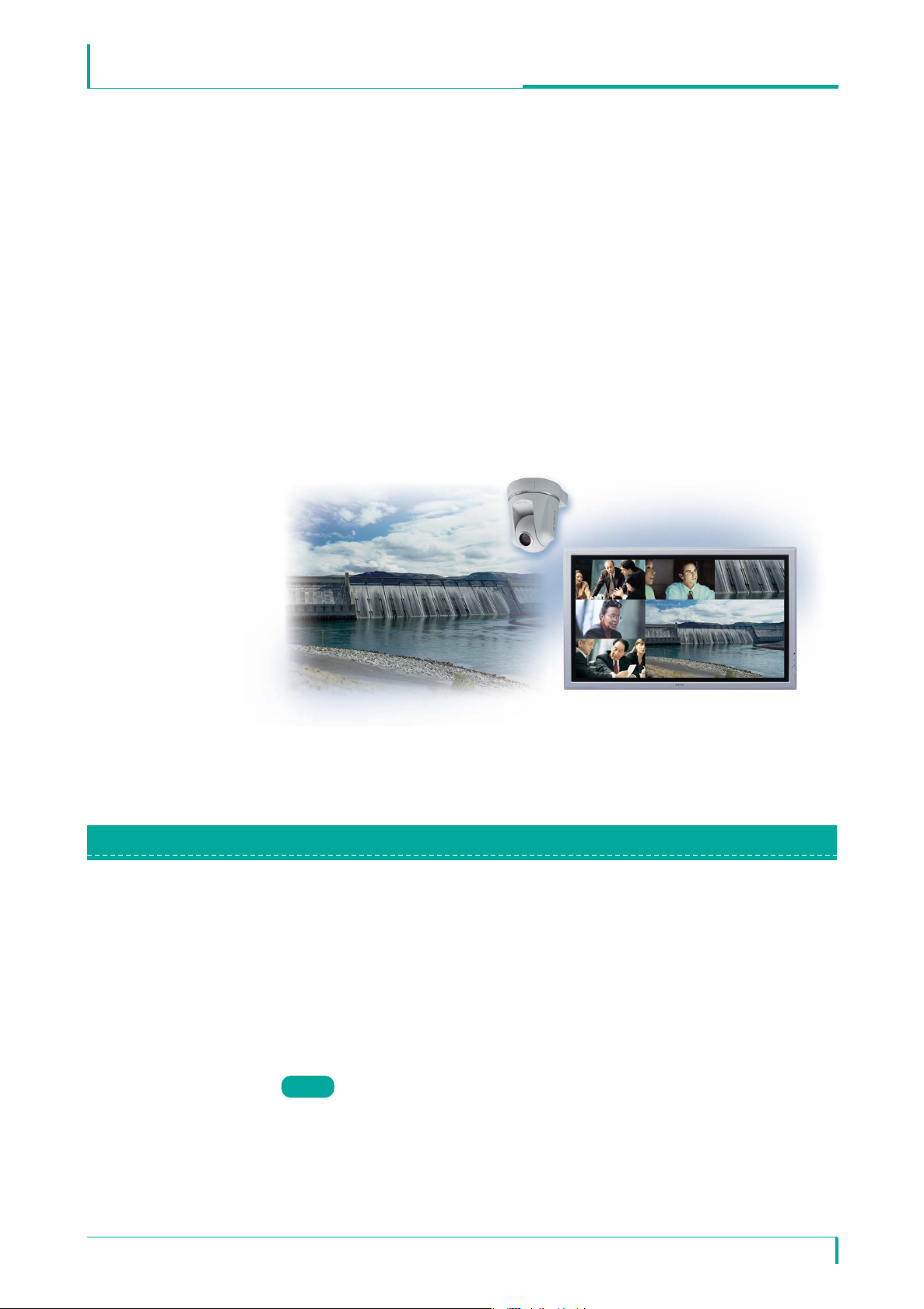
User Authority
(This image illustrates the connection between video communication terminals and network cameras.
The screen image is simulated.)
Multiple users can be registered for a Sony network camera, and a name,
password and authority can be specified for each user. Connection from the
PCS-G50/G70 to a network camera is made using a predefined user name and
password. The operation and settings for a network camera can be limited based
on the user authority.
Network Camera User Authority
Table 1 shows the functions available for the administrator and user authorities.
Note
Only those functions related to PCS integration are listed.
February, 2008 / Ver 1.0©2008 Sony Corporation
5
Page 6

Integration with Sony Network Camera
Table 1
VIDEO COMMUNICATION SYSTEM-TECHNICAL DOCUMENTATION
Authority
Administrator
Function
Monitor live image
Call up preset position*
Perform pan/tilt/zoom
operations
Receive audio ●●●●
Control the setting menu*
● : Function available × : Function not available
*
1: Up to 6 preset positions can be used.
Through the PCS-G50/G70, you can call any of the six registered preset positions (No.1 to No.6) in the preset position
table in the network camera's Preset Position Menu.
*2: This function overwrites the network camera's settings. See the “Determined Communication Mode Based on
Authority” section for details.
1
2
●●●●
●●●×
●●××
● ×××
Full Pan/ Preset Light View
Tilt Position
User
Operating with Administrator Authority in PCS Integration
When you connect using the administrator authority, you can change the settings
of a network camera from the PCS-G50/G70. You can change the settings through
the Network Camera page in the PCS's General Setup menu. If "Auto" is selected
for "Bit Rate," "Frame Rate," "Mode" and "Image Size," the connection is made
using the settings of the connecting network camera.
If the connection is made using the administrator authority with the setting items
set to "Auto," the connection can be made by properly changing the network
camera settings even if a preconfigured item in the network camera setup is not
supported by the PCS-G50/G70. For details on the communication modes
supported by the PCS-G50/G70, refer to "Basic Specifications" at the end of this
document.
In addition, the far end camera control and preset functions can be used under the
administrator authority.
When the network camera settings are changed via the PCS-G50/G70, the
previously set network camera settings are automatically restored after
communication has ended.
Note
• Connections made using the administrator authority automatically change the
network camera settings and may affect a monitoring system using the network
camera, so you must consult with your system administrator beforehand.
• If a connection shuts down due to a failure such as a blackout, the settings
cannot be restored. It is therefore recommended to save the camera's setting
data in a file prior to connection. For details on how to save/restore the setting
data, see the User's Guide that came with the network camera.
February, 2008 / Ver 1.0©2008 Sony Corporation
6
Page 7

Integration with Sony Network Camera
When a connection to a network camera is made using the administrator
authority, the modes described below will automatically be changed.
• Audio Codec
If the audio codec setting (used to send audio) of the network camera is G.726, it
will automatically be changed to G.711.
• Audio (Bidirectional)
If the audio upload setting of the network camera is disabled, it will automatically
be enabled to perform voice communication from the video communication
terminal to the network camera. If the microphone setting of the network camera is
OFF, it will automatically be turned ON to perform voice communication from the
network camera to the video communication terminal as well.
• Multicast Streaming
If the multicast streaming setting of the network camera is OFF and the connection
is made through UDP (Multicast), multicasting will automatically be turned ON for
the connection using UDP (Multicast).
VIDEO COMMUNICATION SYSTEM-TECHNICAL DOCUMENTATION
• Unicast Streaming
If the network camera's unicast streaming setting (video or audio port number)
overlaps with the port number used by the PCS-G50/G70, it will automatically be
changed to another number for connection.
Operating with User Authority in PCS Integration
You cannot change the network camera setting items through the PCS-G50/G70.
You must use the network camera to configure settings related to the connection
with the PCS-G50/G70. (Settings configured through the Network Camera page in
the PCS's General Setup menu will be disabled.)
To use the camera control and preset functions via the PCS-G50/G70, you must
properly configure the network camera's User menu. (See Table 1.)
February, 2008 / Ver 1.0©2008 Sony Corporation
7
Page 8

Integration with Sony Network Camera
Authority Used for Connection
Camera Menu Setting
(on Network Camera)
Administrator User
Connection is made using the PCS setting value
regardless of the network camera setting.*
1
When the PCS setting is "Auto," however, the
network camera settings are prioritized.
Connection is made using the PCS setting value
regardless of the network camera setting.
When the PCS setting is "Auto," however,
connection is made by automatically changing
the network camera setting to a mode
supported by the PCS (H.264 single codec).*
1
Connection is made using G.711.
Connection is made using the network
camera setting (H.264 single codec).
Connection is made using the network
camera setting (MPEG4 single codec).
Connection is not possible if no action is
taken.
To make the connection, use the
network camera to switch the mode to
one that is supported by the PCS.
Connection is made using the network
camera setting (G.711).
H.264
MPEG4
Connection is made using the network
camera setting (QQVGA).
Connection is made using the network
camera setting (QVGA).
JPEG
Dual Codec
G.711
Connection is made by automatically changing
the network camera setting to the audio codec
supported by the PCS (G.711) regardless of the
network camera setting. *
1
Audio is not available between the
video communication terminal and
network camera.*
2
G.726
Connection is made using the PCS setting value
regardless of the network camera setting.
When the PCS setting is "Auto," however,
connection is made by automatically changing
the network camera setting to an image size
supported by the PCS (QVGA). *
1
Connection is not possible if no action is
taken.
To make the connection, use the
network camera to switch the image
size to one that is supported by the PCS.
VGA
Connection is made using the PCS setting value
regardless of the network camera setting.*
1
When the PCS setting is "Auto," however, the
network camera setting is prioritized.
QQVGA
QVGA
Connection is made using the network
camera setting.
Connection is made using the PCS setting value
regardless of the network camera setting.*
1
When the PCS setting value is "Auto," however,
the network camera setting is prioritized.*
3
Bit Rate
Connection is made using the PCS
setting. In addition, the network camera
setting is required.*
4
Connection is made using the PCS setting value
regardless of the network camera setting. *
1
Transmission Mode
(TCP/UDP)
Frame Rate
Mode Audio Codec Image Size
Single Codec
Determined Communication Mode Based on Authority
(“PCS” in the table below refers to the main terminal of the PCS-G50/G70.)
VIDEO COMMUNICATION SYSTEM-TECHNICAL DOCUMENTATION
*1: When the network camera settings are changed for the connection, the previously set network camera settings are
automatically restored after communication has ended.
*
2: Videoconferencing connection is possible, even if G.726 is selected. Upon connection, a message is displayed
prompting the user to switch the audio codec.
To use audio for videoconferencing, switch to G.711 on the network camera.
*3: Even if 30fps is selected, the rate is automatically set to 15fps (NTSC) or 12fps (PAL) if the mode is H.264 and the
transmission mode is TCP.
*4: If the network camera setting is improper, a message is displayed prompting the user to make the proper setting.
February, 2008 / Ver 1.0©2008 Sony Corporation
8
Page 9

Integration with Sony Network Camera
How to Configure User Authority
User authority must be configured on both the network camera and the
PCS-G50/G70. This section provides an overview of the settings. For details, see
the User's Guide that came with the network camera and the PCS-G50/G70
Operating Instructions Manual (Version 2.6).
On Network Camera
Register users beforehand in the User menu in the Administrator menu.
VIDEO COMMUNICATION SYSTEM-TECHNICAL DOCUMENTATION
On PCS-G50/G70
On the network camera list edit screen, enter a name and IP address for the
camera you want to register, as well as the user name and password specified on
the network camera.
(To connect using the administrator authority, the user name and password must
be registered as "Administrator" in the network camera's User menu.)
February, 2008 / Ver 1.0©2008 Sony Corporation
9
Page 10

Integration with Sony Network Camera
Operational Specifications Connection
Condition
1-a
Determined Communication Mode
Authority
When sub-terminals are
connected within the
range of the LAN
bandwidth of the main
PCS
When each setting on the main PCS's
network camera page is set to a setting other
than "Auto":
Connection is made using the setting values of
the main PCS. The operation mode and image
size are always determined by the PCS setting
values. (They cannot be changed
automatically.)
When each setting on the main PCS's
network camera page is set to "Auto":
In principle, operations follow each network
camera's setting values.*
1
Administrator
Authority
User
Authority
See
example
1-a-1(1)
1-b
When sub-terminals
exceed the range of the
LAN bandwidth of the
main PCS
When the bit rate exceeds the PCS's LAN
bandwidth, it is automatically changed to the
optimum rate regardless of the main PCS's
network camera settings.
Administrator
Authority
See
example
1-b-1
When the bit rate exceeds the PCS's LAN
bandwidth, it is automatically changed to the
optimum rate for cameras connected with the
administrator authority, while the mode is
changed to "Voice Only" for cameras connected
with the user authority if capability exchange is
required again, regardless of the main PCS's
network camera settings.
Mixed
Administrator
and User
Authority
See
example
1-b-3
When the bit rate exceeds the PCS's LAN
bandwidth, the mode is changed to "Voice Only"
from the added camera regardless of the main
PCS's network camera settings.
User
Authority
See
example
1-b-2
See
example
1-a-1(2)
Regardless of the main PCS's network camera
settings, operations follow each network
camera's setting values.
See
example
1-a-2
Mixed
Administrator
and User
Authority
Cameras connected with the administrator
authority and cameras connected with the
user authority operate independently of each
other, with the specifications described above.
VIDEO COMMUNICATION SYSTEM-TECHNICAL DOCUMENTATION
Communication Mode for Multipoint Connection
The operation specifications and the determined communication mode may vary
according to the user authority used for connection.
Some examples are provided below. (“PCS” in the table below refers to the main
terminal of the PCS-G50/G70.)
Operational Specifications 1: When only network cameras are connected as
sub-terminals
*1: The PCS automatically switches communication modes not supported by the PCS (JPEG, dual codec, VGA, G.726,
30fps on H.264 and TCP) to a supported one.
February, 2008 / Ver 1.0©2008 Sony Corporation
10
Page 11

Integration with Sony Network Camera
2-a
When sub-terminals
are connected within
the range of the LAN
bandwidth of the main
PCS
When a communication terminal is
connected as a sub-terminal, the current PCS
rule is applied to the bit rate regardless of the
main PCS's network camera settings.
When a communication terminal is
connected as a sub-terminal, the mode is
changed to "Voice Only" for all cameras that
require capability exchange again regardless
of the main PCS's network camera settings.
Administrator
Authority
User
Authority
See
example
2-a-1
2-b
When sub-terminals
exceed the range of the
LAN bandwidth of the
main PCS
When a communication terminal is
connected as a sub-terminal, the bit rate is
changed to the optimum rate regardless of the
main PCS's network camera settings.
Administrator
Authority
See
example
2-b-1
Cameras connected with the administrator
authority and cameras connected with the
user authority operate independently of each
other, with the specifications described above.
Mixed
Administrator
and User
Authority
See
example
2-b-3
When a communication terminal is
connected as a sub-terminal, the mode is
changed to "Voice Only" for all cameras that
require capability exchange again regardless
of the main PCS's network camera settings.
User
Authority
See
example
2-b-2
See
example
2-a-2
Mixed
Administrator
and User
Authority
Cameras connected with the administrator
authority and cameras connected with the
user authority operate independently of each
other, with the specifications described above.
See
example
2-a-3
Operational Specifications Connection
Condition Determined Communication Mode
Authority
Operational Specifications 2: When network cameras and communication terminals are
connected as sub-terminals
VIDEO COMMUNICATION SYSTEM-TECHNICAL DOCUMENTATION
February, 2008 / Ver 1.0©2008 Sony Corporation
11
Page 12

Integration with Sony Network Camera
3-a
When connection is
made within the range
of the main PCS's
frame rate limit
When each setting on the main PCS's
network camera page is set to a setting other
than "Auto":
Connection is made using the PCS setting
values.
When each setting on the main PCS's
network camera page is set to "Auto":
In principle, operation follows each network
camera's setting values.*
1
Administrator
Authority
3-b
When the frame rate
exceeds the main PCS's
frame rate limit
When the frame rate exceeds the PCS's frame
rate limit, it is automatically changed to the
optimum rate regardless of the main PCS's
network camera settings.
Administrator
Authority
See
example
3-b
Cameras connected with the administrator
authority and cameras connected with the
user authority operate independently of each
other, with the specifications described above.
Mixed
Administrator
and User
Authority
When the frame rate exceeds the PCS's frame
rate limit, the mode is changed to "Voice
Only" for all cameras that require capability
exchange again regardless of the main PCS's
network camera setup.
User
Authority
User
Authority
Regardless of the main PCS's network camera
settings, operation follows each network
camera's setting values.
Mixed
Administrator
and User
Authority
Cameras connected with the administrator
authority and cameras connected with the
user authority operate independently of each
other, with specifications described above.
Operational Specifications Connection
Condition Determined Communication Mode
Authority
Operational Specifications 3: When the frame rate limit is exceeded
If the frame rate limit has been exceeded, it means that 4 or more terminals with
30fps are connected.
VIDEO COMMUNICATION SYSTEM-TECHNICAL DOCUMENTATION
*1: The PCS automatically switches communication modes not supported by the PCS (JPEG, dual codec, VGA, G.726,
30fps on H.264 and TCP) to a supported one.
February, 2008 / Ver 1.0©2008 Sony Corporation
12
Page 13

Integration with Sony Network Camera
DescriptionExample Setting Example/Determined
Communication Mode
1-a-1(1)
Main Terminal
Camera 1
1024kbps/15fps
Camera 2
512kbps/15fps
When the sum of the network camera bit rates
(1024kbps + 512kbps) does not exceed the main PCS's
LAN bandwidth (4Mbps) and when each setting on the
main PCS's network camera page is set to a setting other
than "Auto," cameras 1 and 2 are connected using the
PCS setting values.
In the example above, camera 1 is configured via the
network camera settings to have a 1024kbps bit rate, but
the rate is automatically changed to 512kbps when
connected to the PCS.
Settings on Main Terminal (PCS)
Determined Com. Mode on Sub-terminal
Camera 1
Each camera is connected
using the values (bit rate,
frame rate, mode and
image size) specified by
main terminal.
Camera 2
Communication Setup:
LAN Bandwidth: 4Mbps
General Setup/Network Camera:
Bit Rate: 512kbps
Frame Rate: 15fps
Mode: H.264
Image Size: QVGA
1-a-1(2)
Camera 1
1024kbps/30fps
JPEG/VGA
Camera 2
512kbps/15fps
MPEG4/QQVGA
When the sum of the network camera bit rates
(1024kbps + 512kbps) does not exceed the main PCS's
LAN bandwidth (4Mbps) and when each setting on the
main PCS's network camera page is set to "Auto,"
cameras 1 and 2 operate using the network camera
setting values. Communication mode settings not
supported by PCS, however, are changed automatically.
In the example above, camera 1 is configured as
JPEG/VGA in the network camera settings. When it is
connected to the PCS, it is automatically changed to
H.264/QVGA. However, a mixture of different bit rates,
frame rates, modes (H.264 or MPEG4), and image sizes
(QVGA or QQVGA) can be used.
Settings on Main Terminal (PCS)
Determined Com. Mode on Sub-terminal
Camera 1
Bit Rate:
1024kbps (No change)
Frame Rate:
30fps (No change)
Mode:
Changes from JPEG to
H.264
Image Size:
Changes from VGA to
QVGA
Bit Rate: 512kbps
Frame Rate: 15fps
Mode: MPEG4
Image Size: QQVGA
(No change for any item)
Camera 2
Communication Setup:
LAN Bandwidth: 4Mbps
General Setup/Network Camera:
Bit Rate: Auto
Frame Rate: Auto
Mode: Auto
Image Size: Auto
Main Terminal
Connection Example
VIDEO COMMUNICATION SYSTEM-TECHNICAL DOCUMENTATION
Note
The determined bit rate and frame rate of the network cameras can be checked
through the "Rate" and "Frame Rate" items in the PCS status menu (Page 1/3).
Note that "Rate" in the status menu includes the audio transfer rate.
February, 2008 / Ver 1.0©2008 Sony Corporation
13
Page 14

Integration with Sony Network Camera
1-a-2
Camera 1
1024kbps/30fps
H.264/QVGA
Camera 2
512kbps/15fps
MPEG4/QQVGA
When the sum of the network camera bit rates
(1024kbps + 512kbps) does not exceed the main PCS's
LAN bandwidth (4Mbps), cameras 1 and 2 operate using
the network camera setting values.
As shown above, a mixture of different bit rates, frame
rates, modes (H.264 or MPEG4) and image sizes (QVGA
or QQVGA) can be used.
Determined Com. Mode on Sub-terminal
Camera 1
Bit Rate: 1024kbps
Frame Rate: 30fps
Mode: H.264
Image Size: QVGA
(No change for any item)
Bit Rate: 512kbps
Frame Rate: 15fps
Mode: MPEG4
Image Size: QQVGA
(No change for any item)
Camera 2
Camera 2
1-b-1
Camera 1
2048kbps/15fps
Added Camera 2
2048kbps/15fps
When the sum of the network camera bit rates
(2048kbps + 2048kbps) exceeds the main PCS's LAN
bandwidth (4Mbps) due to the connection of camera2 *2,
the bit rate is changed to the optimum value for cameras
1 and 2 regardless of the main PCS's network camera
settings.
Settings on Main Terminal (PCS)
Determined Com. Mode on Sub-terminal
Camera 1
Bit rates are changed to
the optimum value for
each camera when they
are connected.
Camera 2
Communication Setup:
LAN Bandwidth: 4Mbps
General Setup/Network Camera:
Bit Rate: Auto
Frame Rate: Auto
Mode: Auto
Image Size: Auto
Main Terminal
Main Terminal
1-b-2
Camera 1
2048kbps/30fps
H.264/QVGA
Added Camera 2
2048kbps/30fps
When the sum of the network camera bit rates
(2048kbps + 2048kbps) exceeds the main PCS's LAN
bandwidth (4Mbps) due to the connection of camera 2 *2,
the mode changes to "Voice Only" for the terminal
(camera 2) that is exceeding the bandwidth. (Camera 1's
image is displayed.)
Settings on Main Terminal (PCS)
Determined Com. Mode on Sub-terminal
Camera 1
Bit Rate:
2048 kbps
Frame Rate: 30fps
Mode: H.264
Image Size: QVGA
(No change for any item)
Changes to "Voice Only"
mode
Communication Setup:
LAN Bandwidth: 4Mbps
General Setup/Network Camera:
(Disabled even if configured)
DescriptionExample Setting Example/Determined
Communication Mode
Main Terminal
Settings on MainTerminal (PCS)
Communication Setup:
LAN Bandwidth: 4Mbps
General Setup/Network Camera:
(Disabled even if configured)
VIDEO COMMUNICATION SYSTEM-TECHNICAL DOCUMENTATION
*2: If the network camera bit rate is configured as 2048kbps for both cameras 1 and 2, the sum exceeds the 4Mbps of the
PCS's LAN bandwidth because the network camera bit rate does not include audio (G.711 = 64kbps).
February, 2008 / Ver 1.0©2008 Sony Corporation
14
Page 15

Integration with Sony Network Camera
1-b-3
Camera 1
2048kbps/30fps
Added Camera 2
2048kbps/30fps
* In this example, the main terminal connects to camera 1
with the administrator authority and camera 2 with the
user authority.
When the sum of the network camera bit rates
(2048kbps + 2048kbps) exceeds the main PCS's LAN
Bandwidth (4Mbps) due to the connection of camera 2
*
2
,
the bit rate is changed to the optimum value for camera 1
regardless of the main PCS's network camera settings. The
mode for camera 2 is changed to "Voice Only" because
user authority access is allowed and capability exchange
cannot be performed again.
2-a-1
Added Sub-terminal 1
512kbps/15fps
Camera 2
1024kbps/15fps
MPEG4/QQVGA
When a communication terminal is connected as a
sub-terminal and if the sum of the bit rates of the
sub-terminals (512kbps for communication terminal +
1024kbps for camera) does not exceed the main PCS's
LAN bandwidth (4Mbps), the current PCS rule is applied
to the bit rate regardless of the main PCS's network
camera settings.
In the example above, the bit rate of camera 2 is
automatically adjusted to that of sub-terminal 1.
Settings on Main Terminal (PCS)
Determined Com. Mode on Sub-terminal
Te rm inal 1
LAN Bandwidth:
512kbps
Video Frame: 15fps
(No change for any item)
Camera 2
Communication Setup:
LAN Bandwidth: 4Mbps
General Setup/Network Camera:
Bit Rate: Auto
Frame Rate: Auto
Mode: Auto
Image Size: Auto
Determined Com. Mode on Sub-terminal
Bit rate is changed to the
optimum value when
connection is made.
Changes to "Voice Only"
mode
Bit Rate:
Changes from 1024kbps
to 512kbps
Frame Rate:
15fps (No change)
Mode:
MPEG4 (No change)
Image Size:
QQVGA (No change)
Camera 2
DescriptionExample Setting Example/Determined
Communication Mode
Main Terminal
Main Terminal
Settings on Main Terminal (PCS)
Communication Setup:
LAN Bandwidth: 4Mbps
General Setup/Network Camera:
Bit Rate: Auto
Frame Rate: Auto
Mode: Auto
Image Size: Auto
Camera 1
VIDEO COMMUNICATION SYSTEM-TECHNICAL DOCUMENTATION
*2: If the network camera bit rate is configured as 2048kbps for both cameras 1 and 2, the sum exceeds the 4Mbps of the
PCS's LAN bandwidth because the network camera bit rate does not include audio (G.711 = 64kbps).
February, 2008 / Ver 1.0©2008 Sony Corporation
15
Page 16

Integration with Sony Network Camera
2-a-2
Added Sub-terminal 1
384kbps/15fps
Camera 2
512kbps/15fps
When a communication terminal is connected as a
sub-terminal and if the sum of the bit rates of the subterminals (384kbps for communication terminal +
512kbps for camera) does not exceed the main PCS's
LAN bandwidth (1024kbps), the current PCS rule is
applied and the main PCS automatically tries to adjust the
bit rate of camera 2 to that of sub-terminal 1.
In this example, however, the mode for camera 2 is changed
to "Voice Only" because user authority access is allowed
and capability exchange cannot be performed again.
Determined Com. Mode on Sub-terminal
Te rm inal 1
LAN Bandwidth:
512kbps
Video Frame: 15fps
(No change for any item)
Camera 2
Changes to "Voice Only"
mode
2-a-3
Added Sub-terminal 1
512kbps/15fps
Camera 3
512kbps/
15fps
* In this example, the main terminal connects to camera 2
with the administrator authority and camera 3 with the
user authority.
When a communication terminal is connected as a
sub-terminal and if the sum of the bit rates of the subterminals (512kbps for communication terminal +
(1024kbps + 512kbps) for cameras) does not exceed the
main PCS's LAN bandwidth (4Mbps), the current PCS
rule is applied to the bit rate regardless of the main PCS's
network camera settings.
In this example, the main PCS automatically tries to
adjust the bit rates of cameras 2 and 3 to that of
sub-terminal 1, but the mode for camera 3 is changed to
"Voice Only" because user authority access is allowed
and capability exchange cannot be performed again.
Settings on Main Terminal (PCS)
Determined Com. Mode on Sub-terminal
Te rm inal 1
LAN Bandwidth: 512kbps
Video Frame: 15fps
(No change for any item)
Camera 2
Camera 3
Communication Setup:
LAN Bandwidth: 4Mbps
General Setup/Network Camera:
Bit Rate: Auto
Frame Rate: Auto
Mode: Auto
Image Size: Auto
Bit Rate:
Changes from 1024kbps
to 512kbps
Frame Rate:
15fps (No change)
Mode:
H.264 (No change)
Image Size:
QVGA (No change)
Changes to "Voice Only"
mode
Camera 2
1024kbps/
15fps
H.264/QVGA
DescriptionExample Setting Example/Determined
Communication Mode
Main Terminal
Main Terminal
Settings on Main Terminal (PCS)
Communication Setup:
LAN Bandwidth: 1024Mbps
General Setup/Network Camera:
(Disabled even if configured)
VIDEO COMMUNICATION SYSTEM-TECHNICAL DOCUMENTATION
February, 2008 / Ver 1.0©2008 Sony Corporation
16
Page 17

Integration with Sony Network Camera
2-b-1
Added Sub-terminal 1
2048kbps/15fps
Camera 2
2048kbps/15fps
When a communication terminal is connected as a
sub-terminal and if the sum of the bit rates of the
sub-terminals (2048kbps for communication terminal +
2048kbps for camera) exceeds the main PCS's LAN
bandwidth (4Mbps)*3, the bit rate is automatically
changed to the optimum value regardless of the main
PCS's network camera settings.
Determined Com. Mode on Sub-terminal
Te rm inal 1
The bit rate is changed to
the optimum value when
connection is made.
Camera 2
Communication Setup:
LAN Bandwidth: 4Mbps
General Setup/Network Camera:
(Disabled even if configured)
Main Terminal
Main Terminal
2-b-2
Added Sub-terminal 1
2048kbps/15fps
Camera 2
2048kbps/15fps
When a communication terminal is connected as a
sub-terminal and if the sum of the bit rates of the
sub-terminals (2048kbps for communication terminal +
2048kbps for camera) exceeds the main PCS's LAN
bandwidth (4Mbps)*3, the mode for camera 2 is changed
to "Voice Only" because user authority access is allowed
and capability exchange cannot be performed again.
Settings on Main Terminal (PCS)
Determined Com. Mode on Sub-terminal
Te rm inal 1
LAN Bandwidth:
2048kbps
Video Frame: 15fps
(No change for any item)
Camera 2
Changes to "Voice Only"
mode
DescriptionExample Setting Example/Determined
Communication Mode
Settings on Main Terminal (PCS)
Communication Setup:
LAN Bandwidth: 4Mbps
General Setup/Network Camera:
Bit Rate: Auto
Frame Rate: Auto
Mode: Auto
Image Size: Auto
VIDEO COMMUNICATION SYSTEM-TECHNICAL DOCUMENTATION
*3: If the network camera bit rate is configured as 2048kbps for camera 2, the sum of the bit rates of the sub-terminals
(communication terminal and camera) exceeds 4Mbps of the PCS's LAN Bandwidth because the network camera bit
rate does not include audio (G.711 = 64kbps).
February, 2008 / Ver 1.0©2008 Sony Corporation
17
Page 18

Integration with Sony Network Camera
DescriptionExample Setting Example/Determined
Communication Mode
Main Terminal
Main Terminal
2-b-3
Added Sub-terminal 1
2048kbps/15fps
Camera 3
1024kbps/
15fps
* In this example, the main terminal connects to camera 2
with the administrator authority and camera 3 with the
user authority.
When the sum of the bit rates of the sub-terminals
(2048kbps for communication terminal + (2048kbps +
1024kbps) for cameras) exceeds the main PCS's LAN
bandwidth (4Mbps) due to the connection of the
sub-terminal, the bit rate is changed to the optimum value
for camera 2 regardless of the main PCS's network
camera settings, but the mode for camera 3 is changed to
"Voice Only" because user authority access is allowed
and capability exchange cannot be performed again.
Determined Com. Mode on Sub-terminal
Te rm inal 1
Bit rate is changed to the
optimum value when
connection is made.
Camera 3
Camera 2
Changes to "Voice Only"
mode
Camera 2
2048kbps/
15fps
3-b
Sub-terminal 1
30fps
Camera 3
30fps
Added
Camera 4
30fps
* In this example, the main terminal connects to cameras 2
and 4 with the administrator authority and camera 3 with
the user authority.
When the frame rate exceeds the main PCS's frame rate
limit (30fps x 4) due to the connection of camera 4, the
capability exchange of the frame rate is required regardless
of whether the administrator or user authority is used.
In this example, the main PCS automatically tries to
adjust the frame rate of all the sub-terminals to 15fps, but
the mode for camera 3 is changed to "Voice Only"
because user authority access is allowed and capability
exchange cannot be performed.
Settings on Main Terminal (PCS)
Determined Com. Mode on Sub-terminal
Te rm inal 1
Changes from 30fps to 15fps
Changes from 30fps to 15fps
Changes to "Voice Only"
mode
Camera 3
Camera 2
Changes from 30fps to
15fps
Camera 4
Communication Setup:
LAN Bandwidth: 4Mbps
General Setup/Network Camera:
Bit Rate: Auto
Frame Rate: Auto
Mode: Auto
Image Size: Auto
Camera 2
30fps
Settings on Main Terminal (PCS)
Communication Setup:
LAN Bandwidth: 4Mbps
General Setup/Network Camera:
Bit Rate: Auto
Frame Rate: Auto
Mode: Auto
Image Size: Auto
VIDEO COMMUNICATION SYSTEM-TECHNICAL DOCUMENTATION
February, 2008 / Ver 1.0©2008 Sony Corporation
18
Page 19

Integration with Sony Network Camera
Target Network Camera
(As of December 2007)
Transmission Mode
Sony SNC-RX550N/ RX550P (software version 2.1)
Sony SNC-RZ50N/ RZ50P (software version 2.1)
Sony SNC-CS50N/ CS50P (software version 2.1)
UDP (Unicast), UDP (Multicast), TCP
* UDP (Unicast) is recommended
Image Size *
1
320 x 240 (QVGA), 160 x 120 (QQVGA)
Mode *
2
H.264, MPEG4 (single codec only)
Bit Rate When using H.264: 32, 64, 128, 256, 384, 512, 768, 1024, 1536 kbps
When using MPEG4: 64, 128, 256, 384, 512, 768, 1024, 1536, 2048 kbps
Frame Rate *
3
NTSC: 15fps, 30fps
PAL: 12fps, 25fps
Type of Connection Peer-to-peer, multipoint connection
*
4
Up to 6 points (including the local site) can be connected for multipoint
connection with the following configurations:
・ H.323 + network camera
・ H.320 + network camera
・ SIP + network camera
・ MIX MCU (mixture of the above patterns)
Audio Codec G.711
For the latest information on supported cameras and software versions, contact
your Sony sales representative.
Basic Specifications
Basic Specifications
VIDEO COMMUNICATION SYSTEM-TECHNICAL DOCUMENTATION
*1: 640 x 480 (VGA) is not supported.
2: H.264, MPEG4 and JPEG dual codec and JPEG single codec are not supported.
*
3: Up to 15fps (NTSC) or 12fps (PAL) if the mode is H.264 and the transmission mode is TCP.
*
*
4: Multipoint connection requires optional MCU software for LAN connection.
Multipoint connection for mixed SIP and ISDN environment requires optional SIP software and MCU software for
ISDN connection.
Cascade connection is not supported.
February, 2008 / Ver 1.0©2008 Sony Corporation
19
Page 20

 Loading...