

Page 1
ICS-SP30
User Guide
Enseo, Inc.
401 International Parkway
Suite 100
Richardson, Texas 75081
www.Enseo.com
Copyright 2007 – Enseo, Inc.
1
Page 2

Introduction
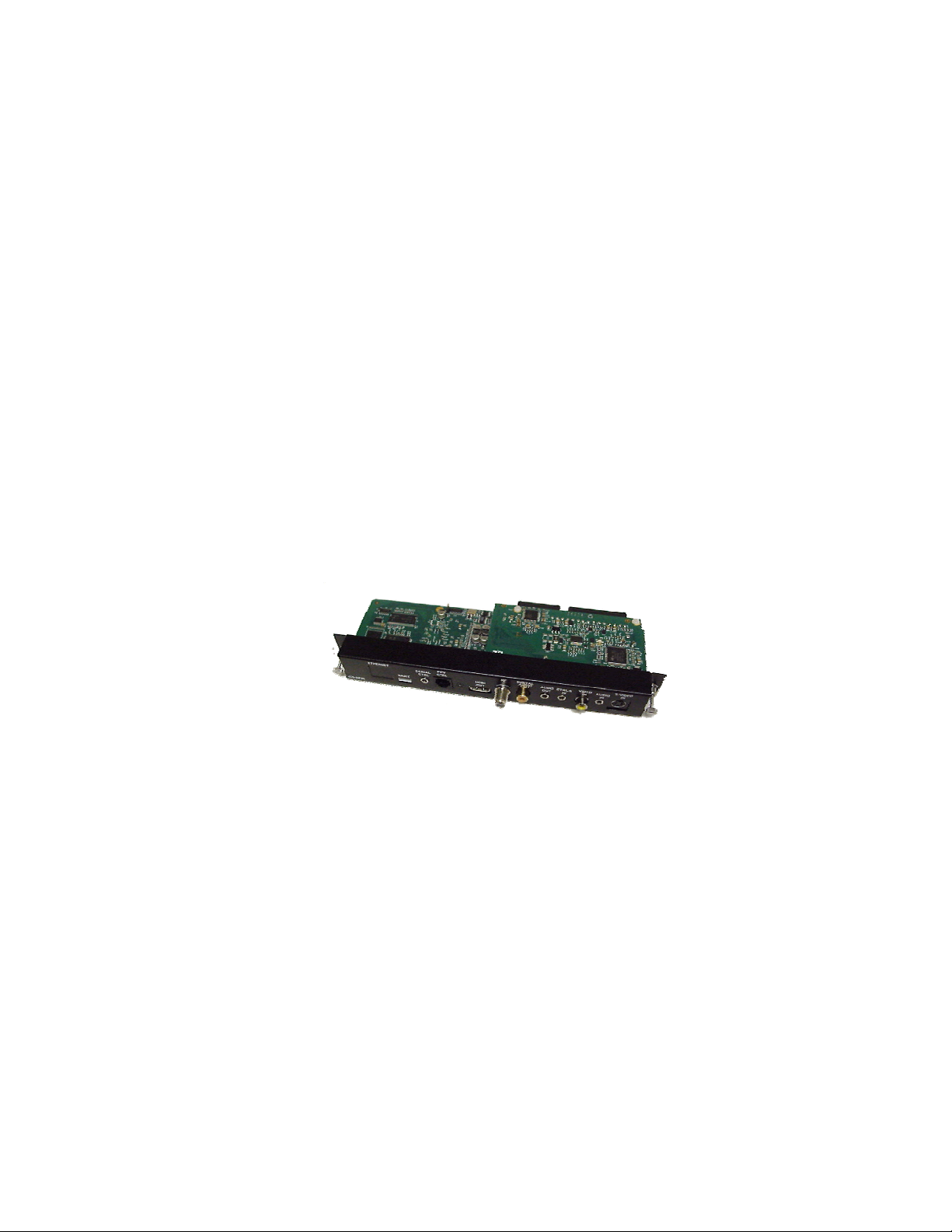
The ICS-SP30 is a professional tri-band tuner providing 8VSB, QAM and NTSC tuner function for
internal connection to a line of Sony Professional LCD and Plasma displays. The ICS-SP30
includes support for Pro:Idiom™ decoding on lodging systems sup porting this encryption
technology.
This document outlines the installation, set up and operation of the ICS-SP30. For questions or
to check for updated information on this product, please check www.sony.com/support
information.
Table of Contents
Hardware / Setup
Shipped Components
Setting up the ICS-SP30 / Connections
Powering On
Menus / Configuration
General Operations
- Remote Control Functionality
- Navigating Menus
Set Up Menu
- Channel Options
- Switch-On Options
- On-Screen Display Options
- Control Options
- Captioning Options
- V-Chip Options
- Service Options
- Exit
User Menu
- Captioning
- Digital Captioning Mode
- Analog Captioning Mode
- Sleep Timer
- SAP
- Source
- Picture Format
- V-Chip Options
- Exit
Operation
General Operation
- Lodging Mode
- Stand-Alone Mode
Troubleshooting / FAQ
Technical Specifications
FCC Statement & Acknowledgement
for more
Copyright 2007 – Enseo, Inc.
2
Page 3

Hardware Setup
Supplied Accessories
(Images not to scale)
ICS-SP30 Card Card Adapter
HDMI Cable
Notes:
Compatible Displays
The ICS-SP30 card is compatible with the following Sony Displays:
KLH-W26
KLH-W32
FWD-40LX1
FWD-32LX2
FWD-40LX2
FWD-50PX2
FWD-42PX2
DVI-HDCP Displays
Some Sony Displays require an HDMI to DVI adapter and audio adapter cable for audio (not
supplied) and may require a longer HDMI cable than the 12” cable supplied (PX2 models). These
include:
FWD-40LX1 FWD-42PX2 FWD-50PX2 FWD-50PX3
Copyright 2007 – Enseo, Inc.
3
Page 4
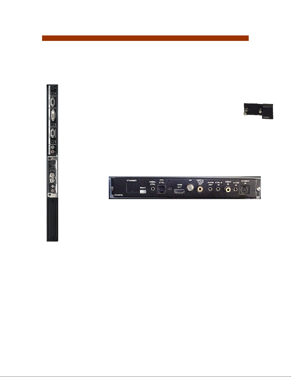
Setting Up the ICS-SP30 / Making Connections
The ICS-SP30 is designed to function with Sony Professional LCD and Plasma displays which
may differ in input types and connection configuration. For questions on connections and
specifications on specific Sony displays, consult www.sony.com/support.
Installing Card
Step 1 – Remove power cord from the display to ensure power is off. Remove
any populated cards in slot 1 and/or slot 2 (if any). There may be a cover
over slot 2. Remove the middle rail guide by removing screw between two
card slots
Step 2 – If inserting the ICS-SP30 into a KLH display, skip to step 3.
For other displays, attach card extender
to left side of the ICS-SP30 and tighten.
The finished card should look like image at right
Step 3 – Carefully insert the ICS-SP30 card into the card slot. Do not allow
components to come into contact with edges of the card slot. Note: S-Video
input should be on the top edge of the card as it is inserted.
DO NOT FORCE CARD
When card is completely inserted, it should fit into the two internal
connectors, and then the thumb screws can be tightened.
Step 4 – Attach the HDMI cable to HDMI Out on the ICS-SP30
(Note: there is a required external HDMI cable from the ICS-SP30 to the digital
input of the display – This is based upon strict requirements for HD tuners in
hospitality)
Step 5 – Attach COAX cable to RF input
Step 6 – Attach RJ12 data cable from PPV Provider box to the PPV CNTL input
Step 7 – Plug power into the Sony Display and using the PPV Provider remote, press
Power button
The unit is now configured for hospitality mode with the PPV Provider.
Copyright 2007 – Enseo, Inc.
4
Page 5
Menus / Configuration
Stand Alone vs. Lodging Mode
The ICS-SP30 is designed to operate in a Pay-Per-View environment, connected to a lodging
system that uses protocols and commands to control the display and tuner. The ICS-SP30 may
also be able to operate in a Stand Alone mode to provide basic TV tuning for the Sony Display.
When the ICS-SP30 is connected to a compatible lodging system, the ICS-SP30 will
automatically recognize the lodging system and respond to the PPV commander. In Lodging
Mode, the control buttons and IR commands from the Sony remote will not control the display and
tuner.
Supported Remote Controls
The ICS-SP30 is designed to function with the remote control that shipped with the Sony display.
Because of differences in the display remotes, in which not all remotes have the same available
buttons, some remotes may have limited functionality with the display remote. In such case, a
standard Sony TV remote or universal remote (such as Sony RM-EZ2) using Sony IR commands
can control the ICS-SP30 in Stand-Alone Mode.
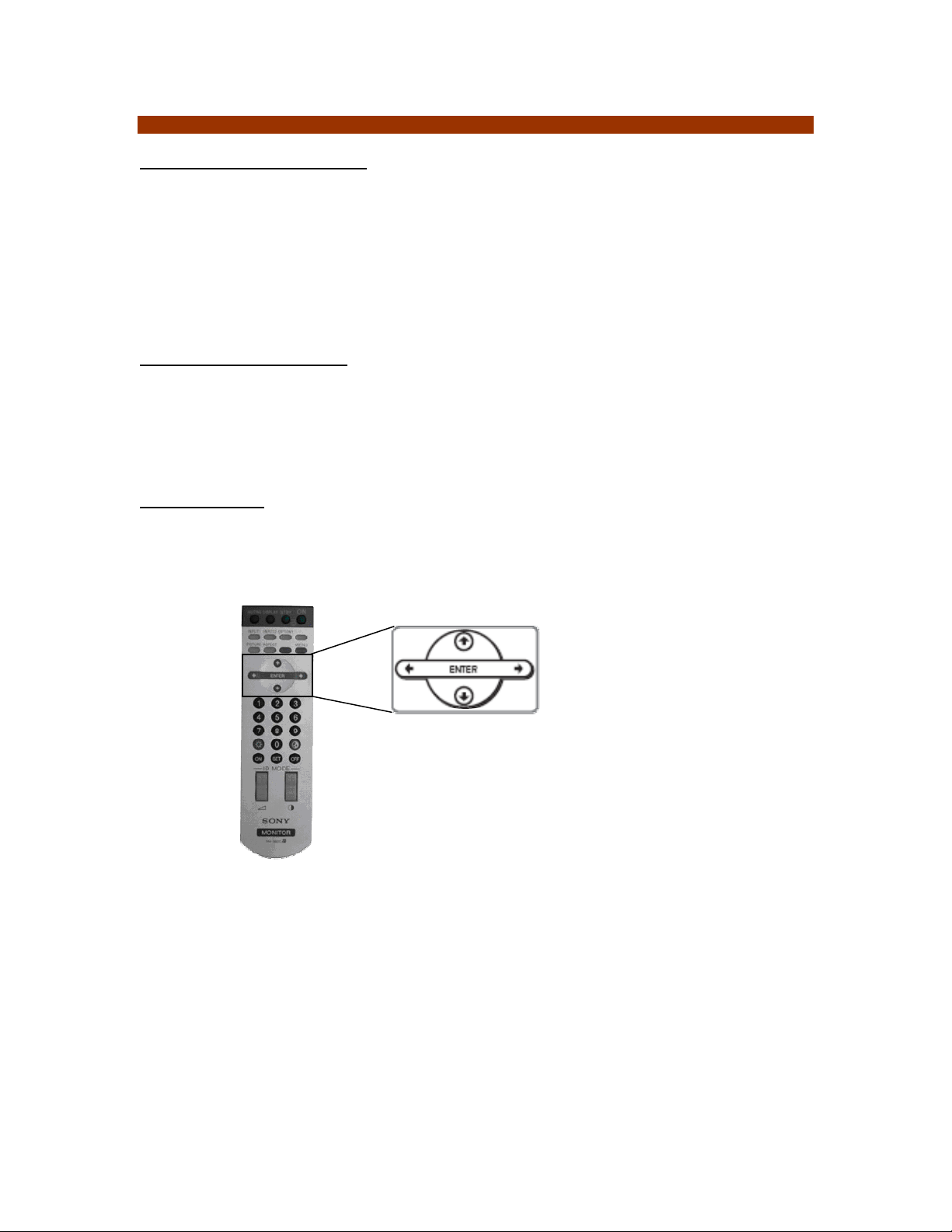
Navigating Menus
The menus in the operation of the ICS-SP30 have been designed to use the Left, Right, Up,
Down buttons for most functions. To return to a previous menu, pressing the Left button
Copyright 2007 – Enseo, Inc.
5
Page 6
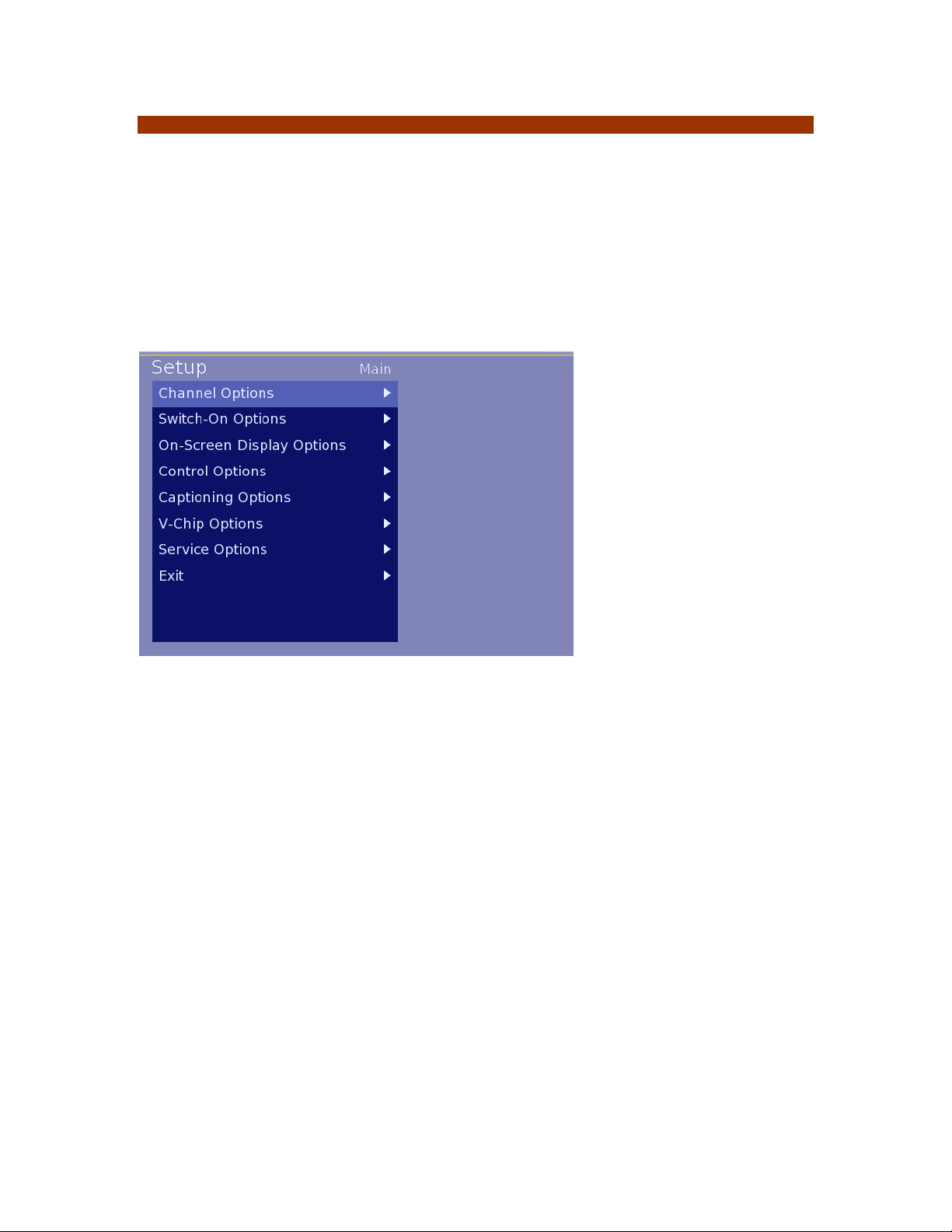
Stand-Alone Set Up Menu
The ICS-SP30 set up process includes a sequence of numbers pressed on the Sony remote to
access the set up menus. With the display and ICS-SP30 powered on press the following in
sequence.
(note: when pressing buttons, press the buttons to be sure the system receives the code.
Setup Menu code: Up Right Left Mute
If a button is pressed in error, press the Down arrow to clear the code entries. In the lodging
environment a different remote or function may be enabled to provide additional security.
Image 1 – Setup Menu
Navigating Menus
Most menus and submenus are navigated using the UP / DOWN / RIGHT / LEFT arrows on the
remote control. To enter a menu, press the RIGHT button.
To enter an item in a sub menu, the ENTER button can be pressed or the LEFT arrow button can
be pressed to exit a entry field and store the setting.
Some sub-menus require specific characters and onscreen instructions will be provided in such
cases.
Copyright 2007 – Enseo, Inc.
6
Page 7
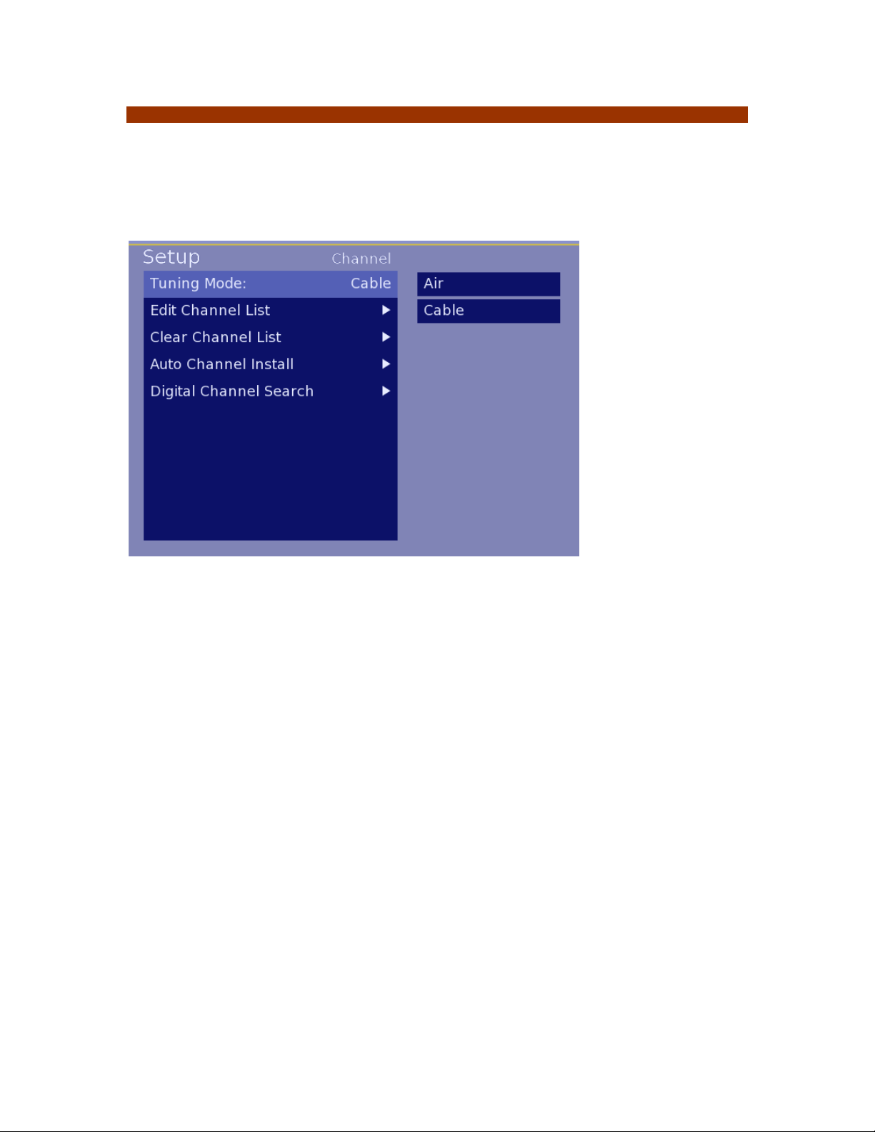
Channel Options
The ICS-SP30 supports analog and digital channels from cable or over-the-air sources.
Note:
Air – To receive over-the-air channels, an antenna and additional equipment may be required
Cable – Digital cable channels may not be accessible if conditional access or subscriptions are
required
Image 2 – Channel Options Menu
Tuning Mode
Option is either Air (Over-The-Air) or Cable. This setting can be changed using RIGHT
arrow button to enter the setting and using UP or DOWN select either Air or Cable. To
save the setting, press the LEFT arrow button.
Edit Channel List
A submenu with functions to add, delete and manage information regarding channels
Clear Channel List
Used to delete the stored channel list programming
Auto Channel Install
Used to scan and install channels
Digital Channel Search
Used to search for digital channels available. Note, these channels will not be
automatically entered into the channel lineup. Digital channels require entry management
on the Edit Channel List menu.
Copyright 2007 – Enseo, Inc.
7
Page 8
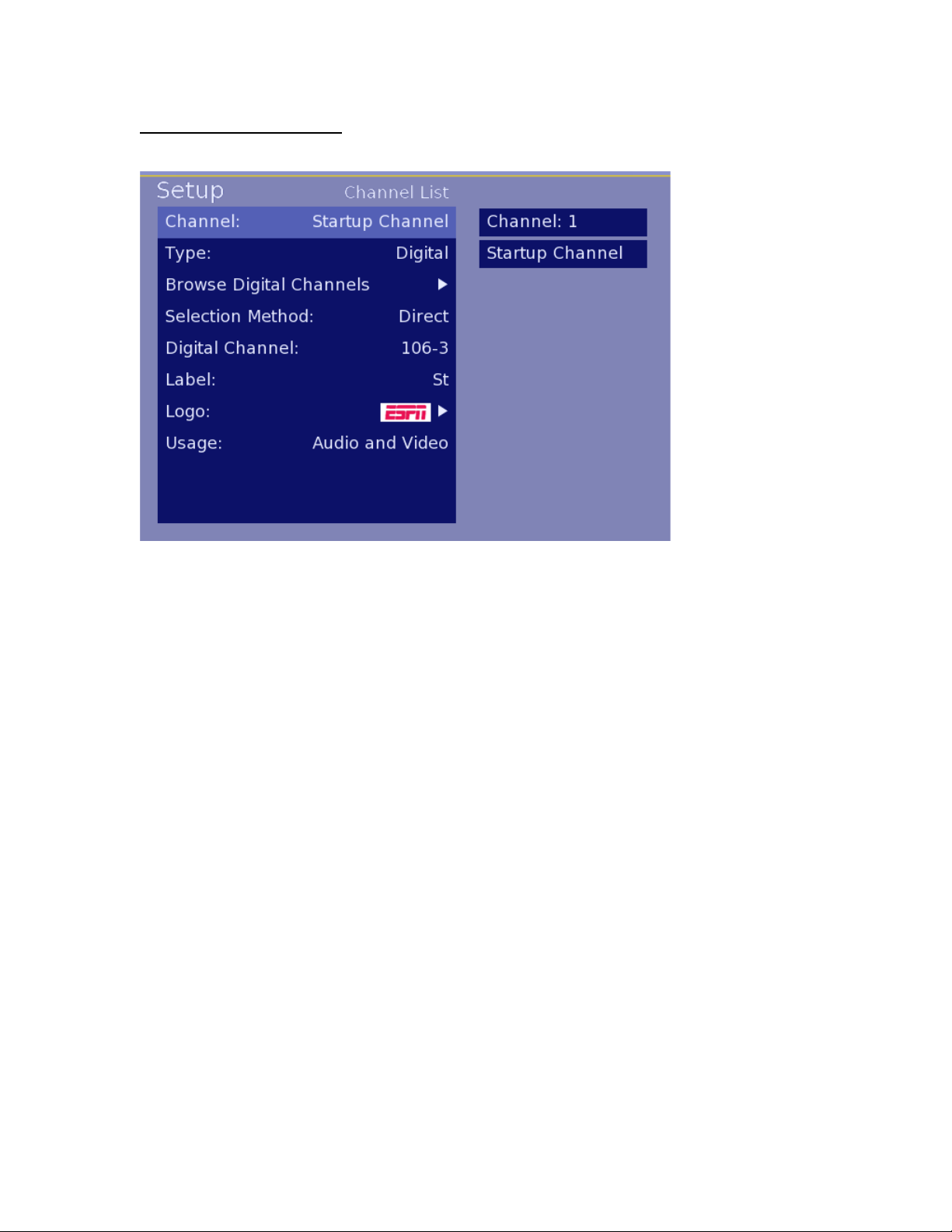
Edit Channel List Submenu
This submenu allows for manual add, delete and management functions of channels.
Image 3 – Edit Channel Submenu
Channel
Using remote, enter the number of the channel to manage, or to setup the Startup Channel,
select Startup Channel
The Startup Channel is a feature to have a specific channel tuned as the default whenever the TV
turns on. The Startup Channel may also be an AV Input in the case where an external media
device is used for the PPV system.
A Startup Channel does not need to be a channel that is in the channel ring.
Include in List
This function allows a channel to be removed from the Channel Ring (available channels) without
losing stored data. Select Yes to include / No to exclude
Type
Selection options include:
Analog – Analog NTSC Channels from 1-127
Digital – Digital Channels – Select Digital to remap the digital QAM or 8VSB channel to
an analog channel number
A/V Input – Provide access to TV A/V Inputs through remapping the input to an analog
channel number
(Note: A/V Input remapping may not function with all PPV providers. For details on using
A/V Inputs while in Lodging Mode, consult the section on A/V Input mapping)
Copyright 2007 – Enseo, Inc.
8
Page 9
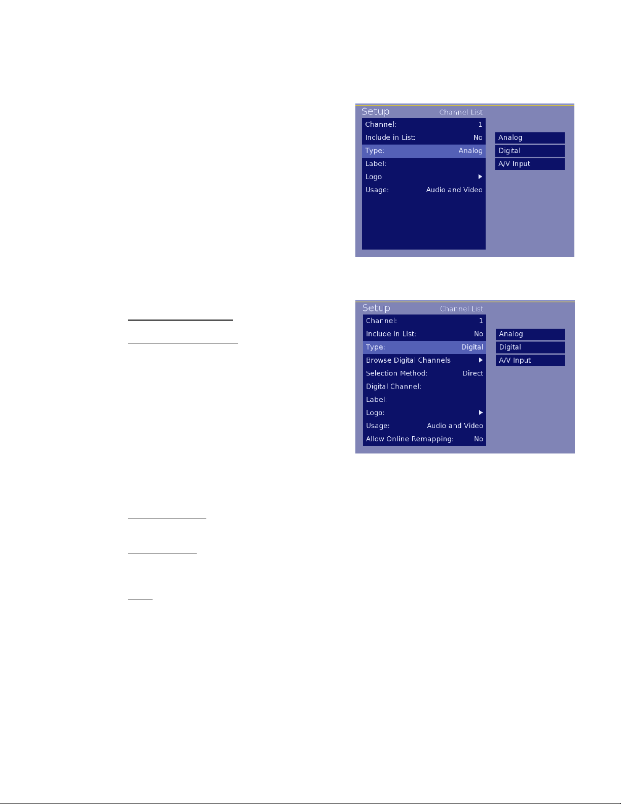
Note:
Depending on the selection type, the menu options will change for the Channel List menu
Analog Type Selection
The options for an analog channel include
a customized Label for the channel, Addition
of a thumbnail logo for the channel and selection
of audio/video options for the channel.
Digital Type Selection
Browse Digital Channels
Available for scanning through digital
channels after they have been scanned
using the Digital Channel Search function
from the Channel Options Menu.
Note: To browse the digital channels,
a standard Sony TV remote, with CH+ / CH-
buttons is required. The remotes provided
with the FWD and KLH model displays do
not include CH+ / CH- buttons and cannot
browse the scanned digital channels.
Selection Method
Allows choice of Virtual or Direct Selection
Digital Channel
This section provides for the entry of the Channel Primary digits and Sub (Program) digits
for the known digital channel
Label
Entry using UP / DOWN arrow buttons to enter a text label for the channel
(Note: PPV systems may not use the label setting in the ICS-SP30 and instead use own
label method. Confirm with your PPV provider if label information will be used)
Image 5 – Analog Channel Settings
Image 6 – Digital Channel Options
Copyright 2007 – Enseo, Inc.
9
Page 10

Logo
Selectable menu of graphical logos for
adding a visual thumbnail for many
popular TV channels
(Note: PPV systems may not use the
logo setting in the ICS-SP30 and instead
use own logo method. Confirm with
your PPV provider if label information
will be used)
Usage
Selection of Audio and Video (default), Audio only for music channels/inputs or video only
for video only usage.
Allow Online Remapping
Note: Not all PPV systems allow Online
remapping. Please consult Enseo at
972-234-2513 to ensure your system is
supported.
NOTE: Lodging System Requirements for Channel Re-mapping
(1) The Lodging System MUST NOT explicitly ‘delete’ the channel
(2) The Lodging System MUST NOT add ‘installation data’ for the channel
(3) The Lodging System MUST use an ‘Analog Channel Tune’ command to
access the re-mapped channel.
This setting is used for Lodging Mode to allow remapping of a Digital Channel or AV Input
to exist in a controlled hospitality system. Select YES to have the settings for the channel
specified maintain the mapped information.
Note: Analog tune commands are the only tune commands that can be re-mapped. If
your PPV provider does not use analog tune commands they will need to implement
them before this function will work.
Note: Before this function is used the PPV provider must be consulted due to differences
in command structures between PPV providers, the necessity to include the re-mapped
channel in the ring, and other proprietary concerns.
Image 7 – Logo Options
Image 8 – Online Remapping Selection
Copyright 2007 – Enseo, Inc.
10
Page 11

Switch-On Options Menu
This menu provides options for setting up default settings for when the display first turns on.
These settings are particularly useful in a lodging environment to be sure the display starts on the
Startup Channel and to pre-define volume, screen format and other settings.
Image 9 – Switch-On Options Menu
Channel
Allows for the configuration of a default channel:
None – Allows PPV system to define startup channel
Startup Channel – Uses the information configured for Startup Channel o n Edit Channel
Submenu. This may include an A/V Input
Restore – Returns the TV to the last channel tuned prior to turning off by user
Volume
Set the numeric value from 0 to 99 that you would like to be used as the default volume
level for the display.
Picture Format
Select between different formats for the screen and content presented. Options include:
Native
This setting will show the aspect ratio of the source material. 4:3 NSTC images
will be shown with side bars
Widescreen
This setting will fill the screen with the image by stretching the image (if
necessary) to create a 16:9 image.
Power
Select the behavior for the ICS-SP30 when AC power is lost and restored. Settings
include:
Copyright 2007 – Enseo, Inc.
11
Page 12

Standby – Return to a standby mode if power is lost or on first plug in
Force On – Turn on TV and Tuner if power is lost or on first plug in
(Note: Force On mode may cause TV to turn on in lodging environment following power
outage)
ON Æ OFF Hold Off Timer
This setting allows for a selectable period of time where the ICS-SP30 will ignore
additional IR button presses during a power off process. This feature is used when
guests may have situations where extra IR presses are causing undesirable interactio n.
OFF Æ ON
This setting allows for a selectable period of time where the ICS-SP30 will ignore
additional IR button presses during a power on process.
Copyright 2007 – Enseo, Inc.
12
Page 13

On-Screen Display Options
The On-Screen Display Options settings provide for customization and set up of OSD options.
Image 10 – On-Screen Display Options Menu
Show Volume Indicator
This menu item is a Yes/No selection for whether a visual representation on the volume
adjustment should be shown on the screen when the user uses the volume up or down
on the remote.
Use 3-Digit Entry
This menu item is a Yes/No selection for support of 3-digit numbers for channels over 99
and digital channels that may use a sub-digit
Show Channel Guide
This menu item is a Yes/No selection for whether a channel guide is active for the user to
see the available channels on the display.
Channel Guide content is generated by the analog channel numbers and text labels for
each channel.
Channel Banner Contents
This menu item allows the selection of the content available on the display banner.
Selections include:
Show number: The channel number
Show Label: The text label for a channel
Show Logo: The select graphic if any
Use the 0 button when selecting or deselecting an option on this sub-menu.
Copyright 2007 – Enseo, Inc.
13
Page 14

Welcome Message Options
This menu item provides for a way to have a
welcome message shown on the display.
Show Message (Yes/No)
Line 1: First line of text
Line 2: Second line of text
Note: If show message is yes
And there is nothing in line one
Or two, the welcome message
Will display “Acquiring Channel”.
Control Options
Image 11 – Welcome Message Submenu
This setup section provides system level settings for the tuner card.
Image 12 – Control Options Menu
ESP (Energy Savings Protection)
This menu item allow for a setting of a default time off to protect against a TV being left
on when a guest leaves a room without turning off the TV. The mode can be set On or
Off, and the hours of inactivity until it turns itself off can be 1 to 9 hours.
Source Menu Item
This menu item is a Yes/No selection and allows control over whether a user, through the
user menu, has access to input selection.
Copyright 2007 – Enseo, Inc.
14
Page 15

Picture Format Menu Item
This menu item is a Yes/No selection and allows control over whether a user, through the
user menu, has access to change the Image Format (widescreen or native).
Minimum Volume
Set the available minimum volume from 0 to 99
Maximum Volume
Sets the available maximum volume from 0 to 99
Setup Key Sequence
Provides a method for changing the key button sequence used to access set up features.
If these are changed, make sure to write down the keys. Failing to record these would
require re-cloning an entire system to restore the set up key sequence.
A key press sequence of up to eight buttons can be defined. These keys are more than
numeric keys and adds to the security for a system.
Image 13 – Setup Key Sequence Submenu
Orbit Options
This submenu provides options available on Sony Plasma monitors to allow selection of
orbit by channel. Orbit is a feature in the Sony Plasma monitors to reduce the potential
for image retention from certain static images.
Sub-menu Options Include
Size
– This is the size of the orbit (how large of an area to shift the display image).
Options include: Small, Medium and Large
Copyright 2007 – Enseo, Inc.
15
Page 16

Cycle Time – This is the duration of
time to complete a full shift of the image
through orbit (includes shifts UP,
RIGHT, DOWN, AND LEFT to complete
an orbit).
The selection options for Cycle Time
are: 10-seconds, 30-seconds, 60seconds, and 5 minutes.
Image 15 – Select Channels
PPV Terminal Options
This submenu provides options for specific hospitality configuration requirements,
including:
Terminal Controls Volume
Default is YES for the lodging terminal device to control the volume. In some specific
installations, this may need to be set to NO for the ICS-SP30 to control the volume
adjustment independent of the lodging system.
Terminal Controls Sleep
Default is YES for the lodging terminal device to control the command settings for the
Sleep Mode. In some specific installations, this may need to be set to NO for the ICSSP30 to directly manage the Sleep Mode independent of the lodging system.
Terminal Controls CC
Default is YES for the lodging terminal device to control the settings for Closed
Captioning. In some specific installations, this may need to be set to NO for the ICSSP30 to control directly manage the Closed Captioning functions independent of the
lodging system.
Auxiliary Control Options
This submenu provides setting for Baud Rate of communications over the service port.
Baud rate of the serial communications port can be adjusted with fixed values from 1200
to 115200.
Note: The shorter the selected cycle
time, the more noticeable the orbit
function will be to the user/viewer.
Select Channels
allows selection/de-selection of specific
channels to implement orbit on.
Channels must be setup and made
available in the channel ring prior to
identifying them for use with the orbit
function.
Text labels in this section are available if
the label information is entered in the
edit channel (Page 8).
– This selection area
Copyright 2007 – Enseo, Inc.
16
Page 17

Captioning Setup
This submenu is used to control the default values for the Closed Captioning function on the
tuner.
Image 16 – Captioning Options Menu
Restore User Setting
This setting allows for the selection of allowing user settings for CC to be stored between
power cycles, or to always use a default setting on power on. Select NO to override the
previous user CC setting on power on (using the default settings), or select YES to allow
the previous user setting to be used on the next power on.
Captioning
This setting allows three options for Closed Captioning at the default power on status.
ON – Closed Captioning will be set to ON at power on
ON WHEN MUTED – This setting will have the ICS-SP30 display Closed Captioning
content when the user Mutes volume.
OFF – This setting has the Closed Captioning set to OFF as the default
Digital Captioning Mode
This setting allows the selection of the CC mode to be used for the Digital Channels
Analog Captioning Mode
This setting allows the selection of the CC mode to be used for the Analog Channels
Copyright 2007 – Enseo, Inc.
17
Page 18

V-Chip Setup
This submenu sets up default options for the V-Chip settings.
Image 17 – V-Chip Options Menu
Restore User Setting
This setting allows for the selection of allowing user settings for V-Chip to be stored
between power cycles, or to always use a default setting on power on. Select NO to
override the previous user V-Chip setting on power on, or select YES to allow the
previous user setting to be used on the next power on.
V-Chip Menu Item
This setting controls whether the user has access to the V-Chip selection and settings.
Selecting YES will allow the V-Chip menu item to appear on the user menu. Selecting NO
will cause the V-Chip settings to no be user accessible and they will not appea r on the
user menu.
Reset Access Code
This is an open setting to allow for the reset of the code. In set up mode, this code can be
overwritten without knowing the previous code. This is useful incase the previous user
forgot the code. The code will be reset to the default code of 0000
Copyright 2007 – Enseo, Inc.
18
Page 19

Default Limits
This section allow for various default values to be set for the tuner.
Image 18 – V-Chip Default Limit Submenu
TV-G = General Audience TV-PG = Parental Guidance Suggested
Image 19 – V-Chip TV Ratings
Enable V-Chip
This setting is a YES/NO selection. By setting YES, the default V-Chip settings
will be active when the ICS-SP30 starts up. Selecting NO disables the V-Chip
settings.
Select TV Ratings
This matrix allows for allowing or restricting various settings, including the TV
industry Parental Guide ratings, and new specific ratings:
TV-Y = All Children TV-Y7 = Directed to Older Children
TV-14 = Parents Strongly Cautioned TV-MA = Mutual Audience Only
FV = Fantasy Violence (cartoons)
V = Violence
S = Sexual Situations
L = Language
D = Suggestive Dialog
Use the arrow keys to highlight a box in the matrix and then use the 0
button on the remote is used to toggle between selections. When
finished, move to the OK box and press 0 to save settings and exit.
Copyright 2007 – Enseo, Inc.
19
Page 20

Image 20 – V-Chip Movie Ratings
Image 21 – V-Chip Reset Function
Select Movie Ratings
This menu allows for the authorization or exclusion of content based on
the
Movie Rating system.
G = Children and Family
PG = Parental Guidance Suggested
PG-13 = Parental Guidance – Special Guidance to children under 13
R = Restricted. No one under 17 without an adult
NC-17 = No children under 17
X = Adult content / Adults only
Not Rated = Some films are not rated and other content is beyond
NC-17 and withdrawn before rating..
Use the arrow keys to highlight a box in the matrix and then use the 0
button on the remote is used to toggle between selections. When
finished, move to the OK box and press 0 to save settings and exit.
Change Access Code
The V-Chip Access Code can be set through the set up process using
this function.
Copyright 2007 – Enseo, Inc.
20
Page 21

Service Menu
The HD tuner is an advanced media device with the ability of communicating through an RF
network to maintain updated firmware and control. The features outlined below are advanced
functions designed for an integrated RF system.
This menu area is used to set up parameters for servicing the tuner or performing service
functions.
Image 22 – Service Options Menu
Update Channel
This feature is used for setting a channel to perform firmware updates. Using the nume ric
keys on the remote, enter the channel that has been identified by your system
administrator for firmware updates.
Allow Update Searching
This YES / NO selection either allows or prohibits the display from searching for an
update channel for firmware updates. Having this selected as YES will allow updates
when the Update Channel needs to be changed for some reason, and eliminates the
need for setting up the update channel at installation.
Start Firmware Update
To manually initiate a firmware update, press the Right arrow button on the remote from
this menu line. NOTE: By selecting this item, the tuner will immediately begin the
firmware update process and reboot when complete.
Copyright 2007 – Enseo, Inc.
21
Page 22

Note:
During a firmware update, the Display MUST NOT be unplugged or turned off.
Doing so while firmware is being downloaded and upgraded on the device could
damage the unit and make it unusable.
If the firmware update was initiated by mistake, it will time out after 3 to 5 minutes.
Start Settings Update
To manually initiate a Clone Setting update, press the Right arrow button on the remote
from this menu line. NOTE: By selecting this item, the tuner will immediately begin
the process of downloading and storing settings stored on the Enseo Galileo
System Server.
Restore Factory Settings
This function allows the tuner to be reset to the factory settings. Changes, channel lineup
programming and other setup customizations will be lost and the tuner will return to
factory settings.
Read TV Settings
This function initiates a Read command in the ICS-SP30 to read the settings values in
the TV. This is used to collect Clone data for a System Clone through the Enseo Galileo
System Server.
Show Status
This menu item will activate a status window showing important information about the
display, tuner, firmware versions and other diagnostic data.
Copyright 2007 – Enseo, Inc.
22
Page 23

USER MENU
User menus are accessed using either the lodging remote provided in the hotel room, or the
remote supplied with the display. These menus are available to users to enjoy the features of the
tuner and display. Only a few control functions are available through the user menus.
Image 23 – User Menu
Captioning
This feature allows the selection of OFF / ON and On When Muted, Using the arrow buttons
highlight the desired setting and then press the Left Arrow button to save and exit the field.
Digital Captioning Mode
This allows the user to select the format of the CC signal for digital channels
Analog Captioning Mode
This allows the user to select the format of the CC signal for analog channels
Sleep Timer
The sleep timer function allows the user to set the TV to turn off automatically after a selected
number of minutes.
Image 24 – Sleep Timer
Copyright 2007 – Enseo, Inc.
23
Page 24

Secondary Audio Programming (SAP)
This menu item allows the user the option of turning on SAP audio if available.
Source
If made user-accessible from the Setup Menu, the user will have the ability to select available
inputs on the display for use of attached media devices. If this feature is not enabled on the
Setup menu, this item will not be visible on the User Menu.
Note: The available inputs will be based on the model of display and video expansion boards
installed (if any).
Picture Format
If made user-accessible from the Setup Menu, the user will have the ability to adjust the aspect
ratio of content presented on the display. If this feature is not enabled on the Setup menu, this
item will not be visible on the User Menu.
Note: On Plasma monitors, user access to Picture Format will be limited to prevent the potential
for image retention.
Image 25 – Picture Format
V-Chip Options
If made user-accessible from the Setup Menu, the user will have the ability to set and control VChip settings to restrict content from being shown on the tuner. If this feature is not enabled on
the Setup menu, this item will not be visible on the User Menu.
Copyright 2007 – Enseo, Inc.
24
Page 25

OPERATION
The HD tuner is an advanced HDTV and NTSC TV tuner with features that support lodging
systems and stand-alone operation.
Lodging Mode
The tuner will automatically function in a lodging mode when attached to a compatible PPV
system. The tuner will communicate with lodging system, identify the system and the
necessary communication protocols and immediately send commands to the display
necessary to function with the attached PPV system.
Stand Alone
To control the tuner in stand-alone mode, the tuner must not be connected to PPV system. If the
display is connected to a PPV system, first disconnect the RJ12 communication cable between
the tuner and the PPV control box. (RJ12 is connected to CONTROL - PPV).
In Stand Alone mode, the tuner will respond to the Sony remote and other compatible PPV
system remotes. To access the User Menu in stand alone mode, press the MENU button on the
remote.
Note on LX2 remote The supplied remote controller for the Sony FWD-32LX2F and FWD40LX2F does not have a Channel Up or Channel Down buttons. To change channels on the
tuner, you must use the UP Arrow or Down Arrow on this remote, or use any Sony TV remote
(such as the Sony RM-EZ2) or universal remote supporting the Sony TV IR commands.
Controlling the Sony Display
The tuner and displays are designed to use the same remote control shipped with the display,
while minimize conflicting commands that could cause the display and tuner to both react.
When the tuner is connected to the display the Sony display will not show the Sony Menu. All
commands to control the display will be controlled by the tuner.
If you need to access the Sony display menu, press in sequence, the following remote buttons:
DISPLAY RIGHT LEFT MUTE
The Sony display will now respond to the Sony remote for menu functions. To exit this mode,
perform the above key sequence again.
Copyright 2007 – Enseo, Inc.
25
Page 26

TROUBLESHOOTING
Troubleshooting
The Display and/or Tuner Do Not Respond to Remote
Possible Remedies
- Check that the display has power attached
- Check that the Communication Cable is correctly attached to the PPV control box.
My Display Does Not Respond to The Remote or Button on the Display
Possible Remedies
- It is possible that the Communication Cable became disconnected during ope ration and the
display must be reset
- Review the Section “Controlling the Sony Display” on Page 18 for further details.
FAQ
Q: Which hospitality systems is the ICS-SP30 Compatible With?
A: The ICS-SP30 is designed to be compatible with most major PPV Hospitality Systems,
including:
- LodgeNet (Tested and Certified Compatible)
- OnCommand (Tested and Certified Compatible)
- SeaChange (Tested and Compatible)
- More…
Most lodging system operate on a similar standard of protocol commands for operation. If a
PPV provider is not listed above, it may be possible for the ICS-SP30 to work with this
provider.
Q: Does the tuner support LG Pro:Idiom™ decryption technology?
A: Yes - The tuner includes the Pro:Idiom decryption technology for support of HD PPV systems
from LodgeNet and OnCommand using Pro:Idiom
Q: What is the warranty on the ICS-SP30 A: The ICS-SP30 has a limited warranty from Sony
against material defects for a period of 12 months from purchase date. For more information on
the warranty, refer to www.sony.com/support.
Copyright 2007 – Enseo, Inc.
26
Page 27

r
Product Specification
ICS-SP30 Specifications
ITEMS
Dimensions
Total Power Consumption
Decryption
Standard
Digital
Analog
Tuner
Inputs
Outputs
OSD Co-ordinate Font, Color & Position
Control
Ports
RF Input
RS232
HDMI
Digital Audio
Analog Audio
Product Safety
EMC
Environmental
English
Display
PPV
L 9.53" x D 3.48" x H 1.18"
8.3 Watts Typical Internal power
QAM/8VSB
NTSC
Pro:Idiom
One
One 3.5mm mini-jack with special cable
With HDCP
S/PDIF
One 3.5mm mini-jack with special cable
Risk Assessment based on IEC60950 Card uses internal power
FCC (Class B)
RoHS
Internal Internal
RJ12 Connecto
DETAILS COMMENTS
MTI command protocol
FCC Statement & License Acknowledgement
This device complies with Part 15 of the FCC Rules. Operation is subject to the following two
conditions: (1) this device may not cause harmful interference, and (2) this device must accept
any interference received, including interference that may cause undesired operation.
Copyright 2007 – Enseo, Inc.
27
 Loading...