

Page 1

USO RESTRITO
MVS-6520
MVS-6530
MVS-3000A
MVS-3000
ICP-6520
ICP-6530
ICP-3000
ICP-3016
ICP-6511
MKS-6550
MKS-6570
Multi Format Switcher System
MVS-6520 System
MVS-6530 System
MVS-3000A System
MVS-3000 System
(With ICP-series Control Panel)
User’s Guide [English]
Software Version 1.10 and Later
1st Edition (Revised 1)
Page 2

USO RESTRITO
NOTICE TO USERS
© 2012, 2013 Sony Corporation. All rights reserved.
This manual or the software described herein, in
whole or in part, may not be reproduced, translated or
reduced to any machine readable form without prior
written approval from Sony Corporation.
SONY CORPORATION PROVIDES NO
WARRANTY WITH REGARD TO THIS MANUAL,
THE SOFTWARE OR OTHER INFORMATION
CONTAINED HEREIN AND HEREBY EXPRESSLY
DISCLAIMS ANY IMPLIED WARRANTIES OF
MERCHANTABILITY OR FITNESS FOR ANY
PARTICULAR PURPOSE WITH REGARD TO THIS
MANUAL, THE SOFTWARE OR SUCH OTHER
INFORMATION. IN NO EVENT SHALL SONY
CORPORATION BE LIABLE FOR ANY
INCIDENTAL, CONSEQUENTIAL OR SPECIAL
DAMAGES, WHETHER BASED ON TORT,
CONTRACT, OR OTHERWISE, ARISING OUT OF
OR IN CONNECTION WITH THIS MANUAL, THE
SOFTWARE OR OTHER INFORMATION
CONTAINED HEREIN OR THE USE THEREOF.
Sony Corporation reserves the right to make any
modification to this manual or the information
contained herein at any time without notice.
The software described herein may also be governed
by the terms of a separate user license agreement.
Page 3
USO RESTRITO
Classification
Functions
supported
Menu No.
See page
System
Control panel type
setting
7316
p. 317
Serial tally
Source address
default setting
7367.1
p. 377
Functions Newly Supported in
Classification
Functions
supported
Menu No.
See page
Transitions
AUX mix transition
On/Off menu
operation
3232
p. 151
AUX mix transition
7142.2
p. 281,
macro event
7142.3
p. 287
support
AUX mix transition
2311
p. 151,
Bus CCR interlock
7333.12
p. 355,
7335.3
p. 357
Multi Viewer
16-split window
setting
7333.9
p. 353
Classification
Functions
supported
Menu No.
See page
Panels
ICP-3000 control
panel connection
–
p. 28
ICP-3016 control
panel connection
–
p. 28
System
Manager
Operation from
System Manager
3211
p. 150
Classification
Functions
supported
Menu No.
See page
System
Control panel type
setting
7316
p. 317
Serial tally
Source address
default setting
7367.1
p. 377
Classification
Functions
supported
Menu No.
See page
Panels
ICP-3016 control
panel connection
–
p. 28
ICP-6520 control
panel connection
–
p. 27
ICP-6530 control
panel connection
–
p. 27
ICP-3000 control
panel and ICP6511 menu panel
connection
–
p. 28,
p. 42
DME
MVE-8000A/9000
multi format DME
processor
connection
41XX
42XX
734X
p. 157,
p. 363
DCU
MKS-8700/2700
device control unit
connection
735X
p. 366
System
Manager
Operation from
System Manager
3211
p. 150
Classification
Functions
supported
Menu No.
See page
Transitions
AUX mix transitions
3232
7333.12
p. 78,
p. 151,
p. 355
Multi Viewer
16-split window
setting
7333.9
p. 353
Version 1.10
Functions relating to the system
The functions newly supported in the MVS-6520/6530
system version 1.10 are as follows.
Functions relating to operability
Functions relating to the system
Functions relating to setup
Functions relating to setup
The functions newly supported in the MVS-3000 system
version 1.10 are as follows.
Functions relating to operability
3
Page 4

USO RESTRITO
4
Table of Contents
Table of Contents
Chapter 1 Overview
Introduction ............................................... 16
Features ..................................................... 17
Basic Video Processing ............................ 18
Transitions................................................... 18
Keys ............................................................ 19
Wipes .......................................................... 20
DME Wipes ................................................ 20
Frame Memory ............................................ 20
Color Backgrounds ..................................... 20
Copy and Swap ........................................... 20
Color Corrector ........................................... 21
Side Flags .................................................... 21
Creation of Special Effects and
Management of Data and
Operations .......................................... 21
Digital Multi Effects (DME) ....................... 21
Controlling External Devices ...................... 22
Keyframes ................................................... 22
Snapshots .................................................... 22
Utilities ........................................................ 22
Shotboxes .................................................... 22
Macros ........................................................ 22
File Operations. ........................................... 23
Setup .......................................................... 23
System Configuration ............................... 24
System Configuration Example ................... 24
Connection Example ................................... 25
Chapter 2 Names and Functions of
Parts
ICP-3016 Control Panel Configuration ........ 28
Cross-Point Control Block
(ICP-6520/6530) ................................ 29
Cross-Point Control Block
(ICP-3000/3016) ................................ 31
Transition Control Block ............................. 34
Device Control Block .................................. 38
Flexi Pad ..................................................... 40
Menu Panel.................................................. 42
Names and Functions of Parts of the
Menu .................................................... 43
Overview ..................................................... 43
Top Menu List ............................................. 43
Menu Screen................................................ 43
Top Menu Window ..................................... 46
Numeric Keypad Window ........................... 47
Keyboard Window ...................................... 48
Color Palette Window ................................. 49
Basic Menu Operations ............................. 49
Recalling Menus .......................................... 49
Selecting Menus .......................................... 50
Selecting List Items ..................................... 50
Setting Parameters ....................................... 50
Returning Parameters to Default Values ....... 51
Operation with a Mouse ................................ 51
Using Shortcut Menus ................................. 51
Switching between the Main Menu Site
and Subsidiary Menu Site ................... 52
Power Supply and Connectors ................. 53
MVS-6520/6530/3000A/3000 Multi
Format Switcher Processor ................. 53
ICP-6520/6530/3000/3016 Control
Panel .................................................. 56
ICP-6511 Menu Panel ................................. 57
Chapter 3 Signal Selection and
Transitions
Names and Functions of Parts of the
Control Panel ...................................... 26
ICP-6520 Control Panel Configuration ...... 27
ICP-6530 Control Panel Configuration ...... 27
ICP-3000 Control Panel Configuration ...... 28
Video Processing Flow .............................. 59
Signal Selection ......................................... 60
Basics of Signal Selection ........................... 60
Bus Selection ............................................... 60
Signal Assignment and Selection ................. 61
Page 5

USO RESTRITO
Table of Contents 5
Interchanging the M/E and PGM/PST
Banks ................................................. 62
Inhibiting Cross-Point Button
Operations. ......................................... 62
Selecting Signals to be Linked with the
Audio Mixer ...................................... 63
Signal Name Display................................... 63
Transitions ................................................ 63
Transition Types .......................................... 63
Procedure for Basic Transition
Operation ............................................ 64
Key Priority Setting .................................. 65
Setting the Key Priority in the Transition
Control Block .................................... 66
Setting the Key Priority by a Menu
Operation ........................................... 66
Displaying the Key Output Status and
Key Priority ....................................... 66
Super Mix Settings ................................... 67
Color Matte Settings ................................. 67
Executing a Transition ............................. 68
Transition Indicator Function ...................... 68
Setting the Transition Rate .......................... 68
Pattern Limits .............................................. 70
Executing an Auto Transition ....................... 71
Executing a Transition with the Fader
Lever (Manual Transition) ................. 72
Combining Auto and Manual
Transitions ......................................... 72
Non-Sync State ........................................... 72
Fader Lever Operation in Bus Fixed
Mode .................................................. 73
Transition Preview .................................... 73
Independent Key Transitions ................... 74
Basic Independent Key Transition
Operations. ......................................... 75
Setting the Independent Key Transition
Rate .................................................... 76
Fade-to-Black ............................................ 77
AUX Mix Transitions ................................. 78
Preparing AUX Mix Transitions ................. 78
Chapter 4 Keys
Overview .................................................... 79
Key Types ................................................... 79
Key Modifiers ............................................. 80
Key Memory ............................................... 81
Key Default ................................................. 81
Key Setting Operations Using Menus ..... 82
Key Setting Menus ...................................... 82
Key Type Setting ......................................... 82
Selecting the Key Fill and Key Source ........ 83
Chroma Key Composition and Basic
Settings............................................... 84
Key Adjustments (Menus) ........................ 85
Chroma Key Adjustments ........................... 85
Key Edge Modifications .............................. 88
Mask ............................................................ 91
Applying a DME Effect to a Key ................ 91
Key Modify Clear ........................................ 92
Blink Function. ............................................ 92
Key Adjustments (Flexi Pad) .................... 92
Resizer ....................................................... 95
Two-Dimensional Transformations and
Rotation of Keys ................................ 95
Resizer Interpolation Settings ....................... 96
Resizer Crop/Border Settings ...................... 97
Resizer Effect Settings ................................ 98
Key Snapshots .......................................... 98
Key Snapshot Operations ............................ 98
Chapter 5 Wipes
Overview .................................................. 101
Basic Wipe Setting Operations .............. 101
Wipe Pattern Selection .............................. 101
Setting Wipe Modifiers ............................. 101
Wipe Modify Clear .................................... 105
Basic Wipe Setting Operations for
Independent Key Transitions .......... 105
Independent Key Transition Wipe
Pattern Selection .............................. 106
Page 6

USO RESTRITO
6
Table of Contents
Setting Independent Key Transition
Wipe Modifiers ................................ 106
Wipe Snapshots ...................................... 107
Wipe Snapshot Operations with the
Menus .............................................. 107
Wipe Pattern Operations in the Flexi
Pad .................................................... 108
Recalling a Wipe Snapshot ....................... 108
Selecting the Wipe Pattern. ....................... 108
Editing the Wipe Pattern ........................... 109
Saving, Canceling, and Deleting Edited
Wipe Patterns................................... 110
Chapter 6 DME Wipes
Overview .................................................. 111
Types of DME Wipe Pattern ..................... 111
DME Wipe Pattern Variations and
Modifiers ......................................... 114
DME Wipe Support (MVS-6520/6530/
3000A) ............................................. 114
DME Wipe Support (MVS-3000) ............. 115
Basic DME Wipe Setting Operations ..... 115
DME Wipe Pattern Selection. ................... 115
Setting DME Wipe Modifiers ................... 116
DME Wipe Modify Clear ......................... 119
Basic DME Wipe Setting Operations
for Independent Key Transitions .... 119
Independent Key Transition DME Wipe
Pattern Selection .............................. 119
Setting Independent Key Transition
DME Wipe Modifiers. ..................... 119
DME Wipe Snapshots ............................. 121
DME Wipe Snapshot Operations with
the Menus ........................................ 121
Creating User Programmable DME
Patterns............................................. 121
User Programmable DME Transition
Mode ................................................ 121
DME Wipe Pattern Operations in the
Flexi Pad ........................................... 123
Recalling a DME Wipe Snapshot ............. 123
Selecting the DME Wipe Pattern .............. 124
Editing the DME Wipe Pattern ................. 124
Saving, Canceling, and Deleting DME
Wipe Snapshots ................................. 125
Chapter 7 Frame Memory
Overview .................................................. 126
Still Image Operations ............................. 127
Preparations ............................................... 127
Interpreting the Frame Memory Menu ...... 127
Selecting an Input Image ........................... 129
Selecting Outputs and Target Frame
Memory ........................................... 130
Capturing and Saving an Input Image ....... 130
Recalling Still Images (Recall) ................. 131
Image Output ............................................... 132
Continuously Capturing Still Images
(Record) ........................................... 133
Recalling a Continuous Sequence of
Still Images (Animation) ................. 134
Frame Memory Clip Function ................. 135
Frame Memory Clip Operations ............. 135
Preparations for Operation ........................ 135
Recalling Clips .......................................... 136
Clip Playback ............................................ 136
Clip Creation ............................................. 138
Creating and Handling Frame Memory
Folders ............................................. 138
Clip Output................................................ 138
Recording and Playback of Ancillary
Data.................................................. 139
Clip Transition Operations ..................... 139
Image Data Management ........................ 141
Pair File Processing ................................... 141
Moving Files ............................................. 141
Deleting Files ............................................ 141
Renaming Files ......................................... 142
Using an External HDD ........................... 142
HDD Formatting ....................................... 142
Saving Files ............................................... 142
Recalling Files ............................................. 143
Managing Images Using a DDR/VTR ...... 143
Using a DDR/VTR for High-speed
Backup and Restoring ...................... 143
Page 7

USO RESTRITO
Table of Contents 7
Extracting Images from a Video Tape ......... 144
Chapter 8 Color Backgrounds, Copy
and Swap, and Other Settings
Color Background .................................. 146
Basic Color Background Setting
Operations. ....................................... 146
Copy and Swap ....................................... 147
Overview of Copy and Swap...................... 147
Copy and Swap Operations ........................ 149
Misc Menu Operations ............................ 149
Port Settings for Control from an
External Device ................................ 149
Safe Title Settings ..................................... 150
Displaying a List of Transition Rates and
Changing the Settings ...................... 150
AUX Mix Transition Settings .................... 151
AUX Menu Operations ............................ 151
AUX Bus Settings ..................................... 151
Status Menu ............................................ 152
Router Control Menu Operations ........... 152
Checking the List of Inputs for Each
Destination ....................................... 152
Switching the Source for Each
Destination ....................................... 152
Chapter 9 Special Functions
Side Flags ................................................ 154
Overview ................................................... 154
Side Flag Settings ...................................... 154
Wipe Action on Images with Side Flags... 155
DME Wipe Action for an Image with
Side Flags ......................................... 155
Chapter 10 DME Operations
Overview ................................................. 157
Devices that Support DME ........................ 157
Three-Dimensional Transformations .................. 157
Transformation Operation Modes .................. 160
Graphics Display ....................................... 161
Three-Dimensional Parameter Display ................ 162
Special Effects ........................................... 162
Global Effects ............................................ 168
Three-Dimensional Transformation
Operations ........................................ 169
Basic Operations ........................................ 169
Three-Dimensional Parameter Display ................ 171
Entering Three-Dimensional Parameter
Values .............................................. 171
Graphics Display Operation ....................... 172
Canceling Virtual Images ........................... 173
Applying Special Effects (Operations
Common to Special Effects) ............. 173
Applying Special Effects (Edge
Effects) .............................................. 173
Border Settings .......................................... 173
Crop Settings ............................................. 174
Beveled Edge Settings ............................... 174
Key Border Settings ................................... 175
Art Edge Settings ....................................... 175
Flex Shadow Settings ................................. 178
Drop Shadow Settings ............................... 181
Wipe Crop Settings .................................... 182
Color Mix Settings ..................................... 183
Applying Special Effects (Overall
Signal Effects) ................................... 184
Defocus Settings ........................................ 184
Blur Settings .............................................. 185
Multi Move Settings. ................................. 185
Sepia Settings ............................................ 185
Mono Settings ............................................ 185
Posterization and Solarization Settings ................ 186
Nega Settings ............................................. 186
Contrast Settings ........................................ 186
Mosaic Settings.......................................... 186
Sketch Settings .......................................... 187
Metal Settings ............................................ 188
Dim and Fade Settings ............................... 188
Glow Settings ............................................ 188
Mask Settings ............................................ 189
Freeze Settings ........................................... 190
Page 8

USO RESTRITO
8
Table of Contents
Applying Special Effects (Nonlinear
Effect Settings) ................................. 190
Wave Settings .............................................. 191
Mosaic Glass Settings ............................... 192
Flag Settings.............................................. 192
Twist Settings ........................................... 193
Ripple Settings .......................................... 193
Rings Settings ........................................... 195
Broken Glass Settings ............................... 195
Flying Bars Settings .................................. 195
Blind Settings ............................................ 196
Split Settings ............................................. 196
Split Slide Settings .................................... 197
Mirror Settings .......................................... 197
Multi Mirror Settings ................................ 197
Kaleidoscope Settings ............................... 198
Lens Settings ............................................. 198
Circle Settings ........................................... 199
Panorama Settings ..................................... 199
Page Turn Settings .................................... 199
Roll Settings .............................................. 200
Cylinder Settings ....................................... 200
Sphere Settings ......................................... 200
Explosion Settings .................................... 200
Swirl Settings ............................................ 201
Melt Settings ............................................. 201
Character Trail Settings............................. 202
Applying Special Effects (Lighting and
Recursive Effects) ............................ 202
Lighting Settings ....................................... 202
Trail Settings ............................................. 204
Motion Decay Settings .............................. 206
Keyframe Strobe Settings ......................... 206
Wind Settings. ........................................... 207
Spotlighting Settings ................................. 208
Applying Special Effects (Other
Effects) .............................................. 215
Background Settings ................................. 215
Separate Sides Settings ............................. 215
Shaped Video Settings .............................. 215
Invert Settings ........................................... 216
Key Density Settings ................................ 217
Key Source Selection ................................ 217
Interpolation Settings ................................ 217
Corner Pinning Settings ............................. 218
Global Effect Operations ......................... 219
Overview ................................................... 219
Combiner Settings ..................................... 220
Brick Settings ............................................ 223
Shadow Settings ........................................ 224
Chapter 11 External Devices
Control of External Devices ..................... 226
Shared Functions for External Device
Control ............................................. 226
Control of P-Bus Devices ........................ 227
Creating and Editing the P-Bus
Timeline ........................................... 227
P-Bus Trigger ............................................ 228
Control of GPI Devices ............................ 228
GPI Timeline Creation and Editing ............ 229
Control of VTRs, Extended VTRs, and
Disk Recorders ................................. 229
Controlling the Tape/Disk Transport .......... 230
Checking VTR/Disk Recorder/Extended
VTR Information ............................. 232
Cueup & Play ............................................ 232
VTR/Disk Recorder/Extended VTR
Timeline ........................................... 234
Disk Recorder/Extended VTR File
Operations ....................................... 237
Chapter 12 Keyframes
Regions .................................................... 239
Registers .................................................. 239
Overview of Keyframes ........................... 240
Effects ....................................................... 240
Saving and Recalling Effects ..................... 240
Effect Attributes ........................................ 240
Effect Editing ............................................... 241
Time Settings ............................................ 241
Paths .......................................................... 242
Effect Execution ........................................ 245
Page 9

USO RESTRITO
Table of Contents 9
Master Timelines ....................................... 245
Sequence of Keyframe Operations ............. 245
Displaying the Timeline Menu ................ 246
Interpreting the Timeline Menu ................. 246
Settings in the Timeline Menu ................... 247
Recalling a Register ................................ 247
Specifying the Region and Edit
Points ................................................ 249
Selecting the Region in which Editing
Applies ............................................. 249
Specifying an Edit Point ............................ 250
Creating and Editing Keyframes. ............ 250
Keyframe Creation and Editing in the
Flexi Pad .......................................... 250
Creation ..................................................... 251
Insertion..................................................... 251
Modification .............................................. 252
Deletion ..................................................... 253
Movement ................................................. 254
Copying ..................................................... 254
Pause ......................................................... 254
Keyframe Loop (Repeated Execution of
a Specified Range) ........................... 254
Undoing an Edit Operation ........................ 255
Duration Mode Setting .............................. 256
Transition Mode Settings for User
Programmable DMEs ....................... 256
Time Settings ................................ .......... 258
Setting the Keyframe Duration .................. 258
Setting the Effect Duration ........................ 259
Delay Setting ............................................. 259
Path Setting ............................................. 259
Basic Path Setting Operations .................... 259
Executing Effects .................................... 260
Executing an Effect in the Flexi Pad ........... 260
Setting the Run Mode ................................ 261
Saving Effects ......................................... 261
Creating and Saving a Master
Timeline ............................................ 262
Creating and Saving a Master Timeline
in the Flexi Pad................................. 262
Creating and Saving a Master Timeline
with the Menu .................................. 263
Register Operations in the Menus ........... 263
Effect Attribute Settings ............................... 264
Effect Status Display .................................. 264
Effect Register Editing ............................... 264
Displaying a List of Effect Registers for
Editing.............................................. 266
Chapter 13 Snapshots
Overview .................................................. 267
Snapshot Types .......................................... 267
Snapshot Attributes .................................... 267
Snapshot Operations in the Flexi Pad .. 268
Banks and Registers ................................... 268
Saving and Recalling Snapshots .................. 269
Snapshot Operations in the Menus .......... 271
Selecting a Region or Reference Region
in a Menu .......................................... 271
Setting Snapshot Attributes ........................ 271
Snapshot Status Display ............................. 273
Setting Key Snapshot Attributes ................. 273
Creating and Saving a Master Snapshot ... 273
Editing Snapshot Registers ........................ 274
Displaying a List of Snapshot Registers
for Editing ........................................ 274
Operations in the Misc >Snapshot
Menu ................................................ 274
Chapter 14 Utility/Shotbox
Utility Execution ...................................... 276
Executing a Utility with the User
Preference Buttons (Menu Panel) ................. 276
Executing a Utility with Cross-Point
Buttons in the 2nd Row ..................... 276
Shotbox ................................................... 277
Shotbox Register Creation ...................... 277
Creating a Shotbox Register in the Flexi
Pad ................................................... 277
Creating a Shotbox Register using the
Menus .............................................. 278
Page 10

USO RESTRITO
10
Table of Contents
Shotbox Execution ................................. 279
Executing a Shotbox in the Flexi Pad .......... 279
Executing a Shotbox Function with Cross-
Point Buttons in the 2nd
Row ................................................. 280
Shotbox Register Editing ....................... 280
Chapter 15 Macros
Macros ..................................................... 281
Overview ................................................... 281
Macro Creation and Editing. ...................... 281
Macro Execution ....................................... 283
Macro Operations in the Flexi Pad .......... 283
Recalling a Macro Register and
Executing a Macro ........................... 283
Creating and Editing a Macro .................... 284
Editing Macros using Menus .................. 287
Macro Register Editing ............................... 287
Online Editing of Macro Events ................. 287
Offline Editing of Macro Events ................ 289
Macro Attachment Assigning ................. 291
Setting and Canceling a Macro
Attachment ...................................... 292
Displaying the Macro Attachment List. ....... 294
Executing a Macro by Macro
Attachment ...................................... 294
Menu Macros ........................................... 295
Recalling a Menu Macro Register and
Executing a Menu Macro ................. 296
Creating and Editing a Menu Macro ........... 297
Menu Macro Register Editing ................... 299
Macro Timeline ........................................ 299
Creating and Editing a Macro Timeline ... 300
Chapter 16 Files
Overview of File Operations ................... 302
Operations on Individual Files ................ 304
Viewing Detailed File Information ............ 304
Selecting Regions ...................................... 305
Selecting a Device for Operations .............. 305
Saving Files ............................................... 305
Loading Files ............................................. 306
Copying Files ............................................ 306
Renaming Files .......................................... 307
Deleting Files ............................................ 307
Saving the List of Frame Memory Files
to a Local Disk or Removable
Disk ................................................. 308
File Batch Operations .............................. 308
Batch Saving Files ..................................... 308
Batch Loading Files ................................... 309
Batch Copying Files .................................. 309
Importing and Exporting Files ................. 309
Importing Frame Memory Data ................. 309
Exporting Frame Memory Data ................. 310
Directory Operations ............................... 310
Creating a New Directory .......................... 310
Renaming a Directory ................................ 311
Deleting a Directory .................................. 311
Copying Files between Different Unit
IDs ...................................................... 311
Saving Files Recalled by Autoload ........... 311
Chapter 17 System Setup
System Settings ....................................... 313
Network Settings ................................ ..... 313
Setting the Group ID .................................. 313
Authenticating the IP Address
Automatically .................................. 313
Setting the Signal Format ........................ 313
Setting the Signal Format .......................... 313
Switching the Input Reference Signal for
HD System ....................................... 314
Setting Conversion Formats ...................... 314
Setting the Screen Aspect Ratio.................. 315
Selecting the State After Power-on .......... 315
Saving and Recalling Setup Data ................ 316
Selecting the State at Start-up ..................... 316
Saving User-Defined Settings .................... 317
Page 11

USO RESTRITO
Table of Contents 11
Setting Automatic Loading of Register
Data at Power On (Autoload
Function). ......................................... 317
Reset and Initialization ........................... 317
Setting the Control Panel Type ............. 317
Installation and Device Setup ................ 317
Installing Software .................................... 318
Configuring the Software for Use ............. 318
Adding User Texture Patterns ................... 319
Saving a Frame Memory Clip with
Ancillary Data .................................. 321
Setting the Number of Format Converter
Input/Outputs ................................... 322
System Maintenance .............................. 322
Setting the Date and Time ......................... 322
Using Removable Disks ............................ 322
Carrying Out the Primary Setting .............. 322
Formatting a Local Disk............................ 323
Locking the Setup Menu Settings .............. 323
Locking File Loading Operations .............. 324
Chapter 18 Control Panel Setup
Overall Control Panel Settings .............. 325
Interchanging the Bank Order or
Disabling Operation. ........................ 325
Linking Switcher Bus and Router
Destination .......................................
Linking Transitions between Keyers ......... 326
Linking the Next Transition Selection
Buttons .............................................
Assigning Regions to Region Selection
Buttons in the Flexi Pad ...................
Setting Transition Control Block Button
Assignments .................................... 327
Assigning Devices or Functions to the
Region Selection Buttons of the
Device Control Block ...................... 328
Inhibiting Utility Bus and Key
Operations. .......................................
Inhibiting DME Channel Selection
Operations. .......................................
325
326
327
328
328
Assigning Functions to the Menu Panel
Top Menu and User Preference
Buttons ............................................. 328
Assigning Functions to the Buttons in
the Flexi Pad .................................... 328
Cross-Point Settings ............................... 329
Creating Cross-Point Assign Tables .......... 329
Setting the Cross-point Button Color for
Each Signal ...................................... 331
Copying Cross-Point Assign Tables ......... 332
Selecting Cross-Point Assign Tables ......... 332
Exporting Source Names and Destination
Names .............................................. 332
Making Settings for Audio Mixer ............. 332
Assigning a Cross-Point Button to
Enable/Disable Side Flags ............... 333
Router Remote Control Settings ............ 333
Assigning a Destination to a Destination
Selection Button ............................... 333
Setting the Source Table ............................ 333
Assigning Levels to a Level Selection
Button .............................................. 333
Selecting a Destination Selection Button
for a Snapshot .................................. 334
Setting Button Assignments .................. 334
Assigning Functions to User Preference
Buttons ............................................. 334
Assigning a Function to 2nd Row Cross-
Point Buttons .................................... 336
Interfacing with External Devices .......... 337
Making Control Panel GPI Input
Settings............................................. 337
Making Control Panel GPI Output
Settings............................................. 338
Assigning a Parallel Output Port ................ 339
Setting the Control Mode for P-Bus
Devices............................................. 339
Associating a Port with a Device
Selection Button ............................... 339
Setting the Serial Ports .............................. 340
Setting the AUX Bus Override Operating
Mode ............................................... 340
Operation Settings .................................. 340
Setting the On-Air Tally ............................ 340
Page 12

USO RESTRITO
12
Table of Contents
Assigning a Bus or Function to 1st Row
Buttons ............................................. 340
Setting the Transition Rate Display
Mode ................................................ 340
Making Settings Relating to Effects ........... 341
Setting the First Keyframe When a
Rewind is Executed .......................... 341
Setting the Source and Destination
Names .............................................. 341
Settings for the Flexi Pad and Wipe
Snapshot Menus ............................... 341
Setting the Button Operation Mode ............ 342
Setting the Operation Mode of the [ALL]
Button in the Transition Control
Block ............................................... 342
Setting Trackball and Button Double-
Click Sensitivity ............................... 342
Setting the Macro Execution Mode ............ 343
Screen Saver and Other Settings ............ 343
Using the Menu Panel Screen Saver ........... 343
Using Panel Sleep Mode ............................ 343
Adjusting the Brightness. .......................... 343
Setting the Touch Operation Beep
Sound ............................................... 343
Calibrating the Touch Panel ...................... 344
Setting the Menu to be Shown When the
Menus Are Started ........................... 344
Setting the Mouse Wheel Scrolling
Direction for Parameter Setting. ........ 344
Selecting the Mouse Button for the
Parameter Setting Buttons ................. 344
Chapter 19 Switcher Setup
Settings for Switcher Configuration ........ 345
Adjusting the Reference Phase .................. 345
Specifying the Video Switching
Timing ............................................. 345
Setting the Operation Mode ....................... 345
Switching Backgrounds using DME
Wipes ............................................... 346
Setting User Regions ................................. 346
Setting the Assignments of DME
Channels .......................................... 346
Setting the Side Flag Video Material and
Operation ......................................... 347
Signal Input Settings ............................... 347
Making Through Mode Settings ................ 347
Configuring the Color Corrector ................ 347
Enabling the Illegal Color Limiter .............. 348
Selecting the Primary Input to be Used in
the Format Converter ....................... 348
Selecting the Input to which the Frame
Delay Function Applies .................... 349
Selecting the Format Converter
Conversion ....................................... 349
Signal Output Settings ............................ 351
Assigning Output Signals .......................... 351
Adjusting the Video Clip ........................... 352
Making Vertical Blanking Interval
Adjustment and Through Mode
Settings ............................................ 352
Making Safe Title Settings ........................ 352
Cropping the Image to a 4:3 Aspect Ratio
in an HD System .............................. 353
Selecting the Output to be Used as the
Format Converter ............................. 353
Setting the Format Converter Outputs ......... 353
Making Settings for the Multi Viewer ......... 353
Enabling AUX Mix Transitions ................. 355
Settings Relating to Video Switching .......... 355
Selecting the Bank to Make the
Settings ............................................ 355
Settings Relating to Keys, Wipes,
Frame Memory and Color
Correction ......................................... 356
Settings for the Show Key Function ............ 356
Settings for Key Auto Drop Function .......... 356
Automatically Naming and Saving to
Frame Memory ................................ 357
Selecting the Bank to Make the
Settings ............................................ 357
Settings Relating to Function Links............ 358
Setting a Cross-Point Button Link .............. 358
Making Link Table Settings......................... 358
Linking Cross-Point Buttons and GPI
Output Ports ..................................... 358
Setting Links between M/E Banks .............. 359
Page 13

USO RESTRITO
Table of Contents 13
Making a Link Setting for Key
Transition ......................................... 359
Interfacing with External Devices ........... 360
Making 9-Pin Port Device Interface
Settings ............................................ 360
Making Switcher Processor GPI Input
Settings ............................................ 360
Making Switcher Processor GPI Output
Settings ............................................ 361
Enabling or Disabling AUX Bus
Control ............................................. 362
Setting the AUX Bus Output and Reentry
Input ................................................. 362
Selecting the Mode for Turning Off Keys
upon Receiving the Editor
Command ......................................... 362
Chapter 20 DME Setup
Signal Input Settings .............................. 363
Setting the Initial Crop .............................. 363
Setting an Illegal Color Limit for Matte
Signals .............................................
Making DME System Phase
Adjustment ...................................... 363
Setting the TBC Window Center
Position ............................................ 363
Signal Output Settings ........................... 363
Adjusting the DME2 Output Video Clip
Level ................................................ 363
Setting the Monitor Output ....................... 364
Interfacing with External Devices .......... 364
Setting the Editor Protocol ........................ 364
Making Editor Port Settings ...................... 364
Making DME GPI Input Settings ............... 364
Making DME GPI Output Settings ........... 365
Chapter 21 DCU Setup
Parallel Input Settings ............................ 366
Assigning a GPI Input Port ....................... 366
363
Releasing the Assignment of a GPI Input
Port. .................................................. 366
GPI Input Setting ...................................... 366
Making DCU GPI Input Settings ..................... 366
Parallel Output Settings .......................... 367
Assigning a GPI Output Port ....................... 367
Releasing the Assignment of a GPI
Output Port ....................................... 368
GPI Output Settings ................................. 368
Making DCU GPI Output Settings ....................... 368
Serial Port Settings .................................. 369
Making Serial Port Settings ........................ 369
Making Detailed Settings on the External
Device Connected to the Serial
Port. .................................................. 369
Chapter 22 Router Interface and
Tally Setup
Router Interface Settings ......................... 373
Assigning Switcher Inputs and Outputs to
Tally Group Settings ................................ 374
Wiring Settings ........................................ 374
Tally Generation Settings ........................ 375
Tally Copy Settings .................................. 376
Parallel Tally Settings .............................. 376
S-Bus Space ..................................... 373
Setting External Boxes 1 to 12 ..................... 373
Making New Wiring Settings ...................... 374
Changing Wiring Settings .......................... 375
Deleting Wiring Settings ............................ 375
Sorting Wiring Settings .............................. 375
Making New Tally Generation Settings.................... 375
Modifying Tally Generation ....................... 375
Deleting Tally Generation Settings ...................... 376
Making New Tally Copy Settings ................... 376
Modifying Tally Copy Settings ...................... 376
Deleting Tally Copy Settings ...................... 376
Making or Modifying Parallel Tally
Settings ............................................. 376
Deleting Parallel Tally Settings ...................... 377
Page 14

USO RESTRITO
14
Table of Contents
Serial Tally Settings ................................ 377
Setting or Changing Serial Tally
Settings ............................................ 377
Making Serial Tally Source Address
Settings ............................................ 377
Chapter 23 User Setup
Source Patch ........................................... 378
Sequence of Source Patch Operations ......... 378
Exporting a User Source Name File to a
Removable Disk............................... 378
Creating a Patch Table (Conversion
Table) .............................................. 378
Replacing Signal Pairs Using the Patch
Table ................................................ 379
Chapter 24 Diagnosis
Checking the Communications
Status. ............................................... 380
Communications Status Display ................ 380
Appendix
Wipe Pattern List ..................................... 381
Wipe Pattern List ......................................... 381
DME Wipe Pattern List ............................... 381
Resizer DME Wipe Pattern List ................. 385
Menu Tree ................................................ 386
M/E-1 Menu. ............................................. 386
PGM/PST Menu ........................................ 389
Color Bkgd Menu ...................................... 390
AUX Menu ................................................ 390
Frame Memory Menu ................................ 391
Copy/Swap Menu ...................................... 391
Misc Menu ................................................ 392
Status Menu .............................................. 392
DME Menu ............................................... 392
Global Effect Menu ................................... 394
Router Menu.............................................. 395
Device Menu ............................................. 395
Macro Menu .............................................. 395
Key Frame Menu ....................................... 396
Effect Menu ............................................... 396
Snapshot Menu .......................................... 397
Shotbox Menu ........................................... 398
File Menu .................................................. 399
User Setup Menu ....................................... 400
Engineering Setup Menu ........................... 401
Diagnostic Menu ....................................... 405
Menus of Disabled Operations and
Settings ............................................. 405
Disabled Menus (MVS-6520/3000A) ............ 405
Disabled Menus (MVS-3000) .................... 408
8-Keyer Operation.................................... 412
Selecting DSK5 to DSK8 Signals in the
2nd Row of the Cross-Point
Control Block ................................... 413
Selecting DSK1 to DSK8 using the Next
Transition Selection Buttons ............ 413
Setting the DSK1 to DSK8 Key
Priority ............................................. 414
Inserting/Deleting DSK1 to DSK8 Using
Independent Key Transitions ............ 414
Independent Key Transition Settings and
Key Snapshot Operations in the
Flexi Pad .......................................... 415
Selecting DSK5 to DSK8 in the Flexi
Pad ................................................... 416
Selecting DSK5 to DSK8 using Menu
VF Buttons ....................................... 416
Selecting DSK5 to DSK8 in the Device
Control Block ................................... 416
Selecting the Range of the Key Wipe
Position Adjustment ......................... 416
Selecting Key 5 or Key 6 Resizer in the
Device Control Block ....................... 417
Menu Access by Pressing a Button
Twice ................................................. 417
Spotlighting ............................................. 419
Texture Patterns ......................................... 419
Shape Patterns ........................................... 419
Functional Differences with DME
Models ............................................... 420
Page 15

USO RESTRITO
Table of Contents 15
Simple Connection of the MKS-8080/
8082 AUX Bus Remote Panel .......... 422
Procedure for Simple Connection ............. 422
Setting Status of the MKS-8080/8082 in
Simple Connection ........................... 422
Macro File Editing Rules ........................ 423
Macro File Syntax ..................................... 423
Syntax of Event and Continue
Statements. ....................................... 423
File Name .................................................. 424
Saving and Recalling a File ....................... 424
Errors ......................................................... 424
Correspondence between Events and
Symbols ........................................... 424
Symbols and Parameters ........................... 425
Example of File Contents .......................... 429
About the Macro Attachment List
Display .............................................. 429
M/E and PGM/PST Banks ........................ 429
Other Blocks .............................................. 430
Menu Operations Not Recorded in a
Menu Macro ...................................... 430
Data Saved by [Setup Define] and
[Initial Status Define] ....................... 431
Data Saved by [Setup Define] ................... 431
Data Saved by [Initial Status Define] ........ 433
Error Messages ....................................... 434
Error Messages Displayed in the Error
Status/Error Log Menu .................... 434
Error Messages Appearing in a Message
Box .................................................. 436
Error Messages Shown in the Error
Information Menu ............................ 444
Maintenance ............................................ 445
Exchanging Button Labels ........................ 445
Care of the Control Panel .......................... 445
Index ........................................................ 446
Page 16

USO RESTRITO
16
Introduction
Formal product name
Term used in this manual
MKS-6570 Digital Multi Effect
Board
• MKS-6570
• DME
• DME board
MVE-8000A Multi Format
DME Processor
• MVE-8000A
• DME
• DME processor
MVE-9000 Multi Format
DME Processor
• MVE-9000
• DME
• DME processor
DCU-8000 Device Control
Unit (MKS-8700)
• MKS-8700
• DCU
DCU-2000 Device Control
Unit (MKS-2700)
• MKS-2700
• DCU
Formal product name
Term used in this manual
MVS-6520 Multi Format
Switcher Processor
• MVS-6520
• Switcher
• Switcher processor
• 2M/E processor
MVS-6530 Multi Format
Switcher Processor
• MVS-6530
• Switcher
• Switcher processor
• 3M/E processor
MVS-3000A Multi Format
Switcher Processor
• MVS-3000A
• Switcher
• Switcher processor
• 2M/E processor
MVS-3000 Multi Format
Switcher Processor
• MVS-3000
• Switcher
• Switcher processor
• 2M/E processor
ICP-6520 Control Panel
• ICP-6520
• Control panel
ICP-6530 Control Panel
• ICP-6530
• Control panel
ICP-3000 Control Panel
• ICP-3000
• Control panel
ICP-3016 Control Panel
• ICP-3016
• Control panel
ICP-6511 Menu Panel
• ICP-6511
• Menu panel
Chapter
1
Overview
System configuration and features
System
nomenclature
System with settings that support
HDTV format
HD system
System with settings that support
SDTV format
SD system
Overview
Introduction
This manual is the User’s Guide for the MVS-6520/6530/
3000A/3000 system Multi Format Switcher.
This manual describes the operation of the MVS-6520/
6530/3000A/3000 multi format switcher processors when
connected to ICP-series control panels.
Device and system nomenclature
Principal components and naming
The formal product names of the principal components of
these systems, and the terms used in this manual are as
follows.
Chapte
An MVS system using the MVS-6520, MVS-6530, or
MVS-3000A Multi Format Switcher Processor is referred
to as the “MVS-6520/6530/3000A system,” and an MVS
system using the MVS-3000 Multi Format Switcher
Processor is referred to as the “MVS-3000 system.”
In this document, the MVS-6520/6530/3000A system and
MVS-3000 system are collectively referred to as the
“MVS system.”
Also, the ICP-6520, ICP-6530, ICP-3000, and ICP-3016
control panels are collectively referred to as the “ICPseries control panel.”
System nomenclature
The following terms are used for systems, depending on
the combination of installed options, and the signal format.
1
r
Illustrations and screenshots
The illustrations and screenshots used in this document to
describe functions and procedures are for an MVS-6520/
3000A switcher processor connected to an ICP-6520
control panel, unless otherwise noted. The operation
buttons and screen display may vary depending on the
system configuration.
Page 17

USO RESTRITO
Features 17
Chapter
1
Overview
Features
The MVS-6520/6530/3000A/3000 system Multi Format
Switcher boasts extensible high performance and
multifunctionality. The following are some of the principal
features of these systems.
System configuration flexibility
Multiformat support
Supports both HDTV and SDTV signal formats.
The format selection can be switched by a simple control
panel operation.
Extensible system configuration
The MVS-6520/6530/3000A supports 2-channel DME
function with an optional MKS-6570 DME board. In
addition, you can connect an MVE-8000A or MVE-9000
extensible DME processor for a maximum of six channels
of DME functionality.
The MVS-3000 can be connected to an MVE-8000A or
MVE-9000 for a maximum of four channels of DME
functionality.
Powerful external device interfaces
By connecting to a Sony routing switcher or similar, a
large system can be built. It is also possible to operate other
equipment, including VTRs and disk recorders, from a
DCU or switcher via a 9-pin serial port.
Powerful tally system
The complete system, including the routing switcher,
provides an all-inclusive tally system. The system can be
adapted to different applications and settings using
multiple tally outputs, including both on-air and recording
tallies.
Format converter board mounting support
An optional MKS-6550 format converter can be installed
in the switcher to provide up-conversion, downconversion, and cross-conversion functions when
importing/exporting signals.
8-
input/0-output or 4-input/2-output groupings are
supported.
Large-capacity data storage
The control panel is equipped with a flash memory drive
(called “local disk”) as standard for storing parameter data,
switcher frame memory static images and other material.
USB-compatible storage devices (called “removable
disks”) can also be connected to the control panel for
storing data.
Comprehensive video manipulation
M/E banks
Each M/E (mix/effects) bank and PGM/PST (program/
preset) bank is equipped with four keyers, and each keyer
is
capable not only of chroma keying, but also independent
key
transitions separate from the background transitions.
Also, the MVS-6530 supports eight keyers in the PGM/
PST rows.
Powerful frame memory functions
The frame memory can hold approximately 1000 frames in
an HD system (approximately 2000 frames in 720P/59.94
format), approximately 5000 frames in an SD system in
480i/59.94 format, or approximately 4000 frames in 576i/
50 format, and allows eight frames to be recalled
simultaneously.
Seamless DME operation with the switcher
The MVS-6520/6530/3000A supports a wide range of
DME functions using the MKS-6570, including DME
wipes and processed key functions as part of the standard
switcher functions.
Multi viewer function
Equipped with two-system multi viewer function, as
standard, for displaying a window split into four, ten, or
sixteen subwindows.
Designed for use in a live broadcasting
environment
High-performance user interface
•
The menu panel provides a large color LCD panel, with
rapid touch-panel menu selection.
You can also operate the menus via a DVI-connected
monitor (or touch panel) and mouse.
•
The cross-point control block uses an organic EL display
with high visibility for the source name display.
•
The buttons in the Multifunction Flexi Pad (hereinafter
called “Flexi Pad”) and ICP-6520/6530 transition
control blocks use color backlit LCD displays. The
signal names, and graphical representations of the
patterns associated with buttons provide intuitive
feedback, and allow the immediate decisions that are
required in a live operating environment.
Rearrangeable M/E rows
On the ICP-6520/6530, the M/E rows can be rearranged
depending on the control panel buttons.
This allows a flexible layout appropriate to the system
operation.
Backup power supply
Equipped with two backup power supplies, as standard.
This alleviates the risk of power supply problems for
improved reliability during live operations.
Page 18
USO RESTRITO
18
Basic Video Processing
Chapter
1
Overview
Basic Video Processing
This section introduces basic functions used for video
processing on the switcher.
Transitions
In the M/E banks and PGM/PST bank, the switch from the
current video stream (appearing on the corresponding
program monitor) to a new video stream is referred to as a
transition.
In the M/E banks and PGM/PST bank, you can change one
of the images, the background, and keys 1 to 4
(downstream keys 1 to 4 in the PGM/PST bank), and also
vary combinations of these simultaneously.
The following are examples of transition.
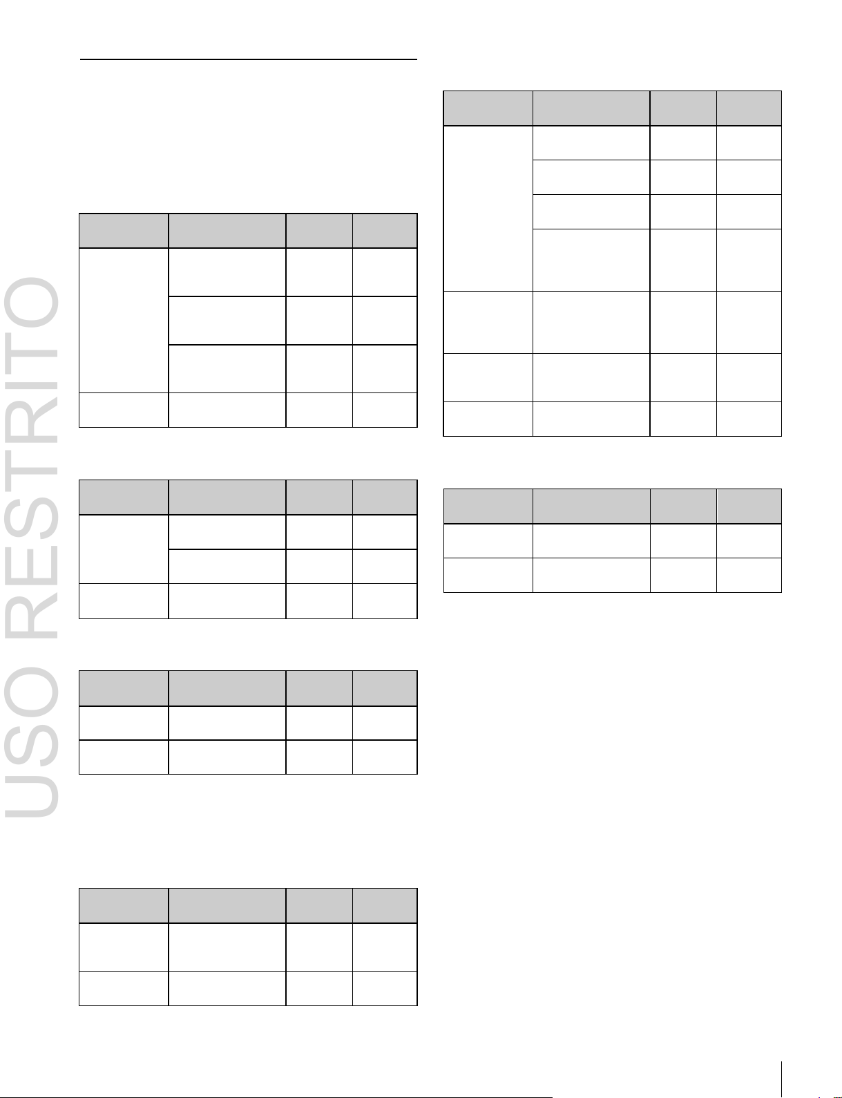
Changing the background
A background transition switches from the video currently
selected on the background A bus (the current video) to the
video selected on the background B bus (the new video).
Transition
In the default selection of flip-flop mode
background always switches in the direction from the A
bus to the B bus. When the transition completes, the crosspoint selections on the A and B buses are interchanged.
Background A Background B
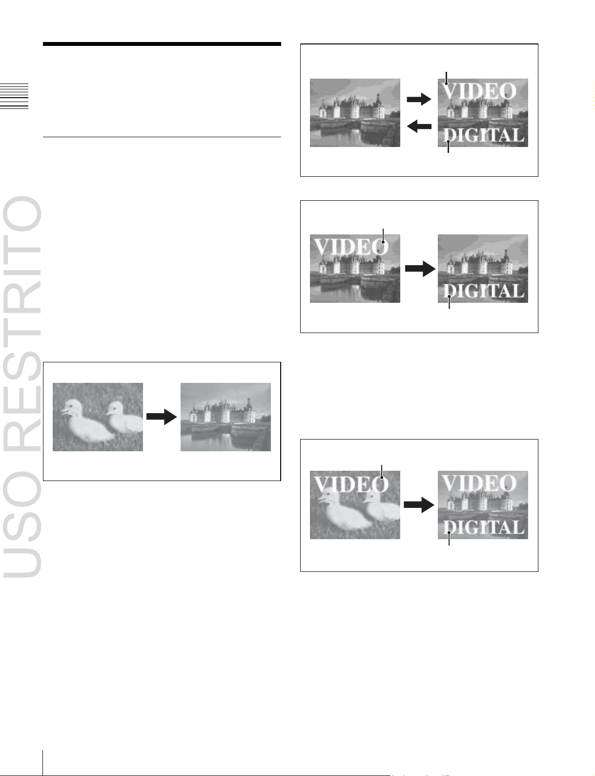
Inserting and deleting a key
You can insert one or more of the four keys (downstream
keys on the PGM/PST bank).
If you select a key which is already inserted, the transition
will delete the key.
A simultaneous combination of deleting and inserting keys
is also possible.
(1 p. 73), the
Key 1
Key 2
Insert
Delete
Inserting or deleting key 1 and key 2
Key 1
Transition
Key 2
Deleting key 1 and inserting key 2
Simultaneously changing the background
and keys
You can change one or more of the four keys (downstream
keys on the PGM/PST bank) and the background at the
same time.
Key 1
Changing the background and keys 1 and 2 simultaneously
Transition
Key 2
Page 19

USO RESTRITO
Basic Video Processing 19
Chapter
1
Overview
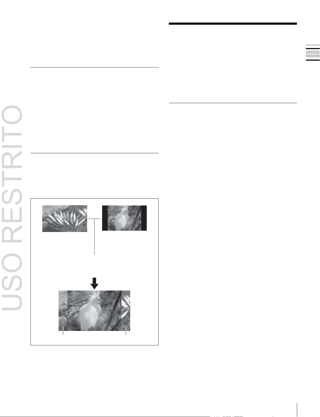
Key 1
Key 3
Effect of a common transition
In the case shown in the previous illustration, carrying out
a common transition produces the following change in the
image.
Transition
Key 2 Key 4
Changing the background and keys 1 to 4 simultaneously
Selecting the transition type determines the way in which
the transition occurs. The following transition types are
available.
•
Mix
•
NAM (non-additive mix)
•
Super mix
•
Preset color mix (color matte)
•
Wipe
•
DME wipe
•
Clip transition
•
Cut
Transition type: Wipe
Same wipe is applied to
Effect of a common transition
background and key.
Effect with use of an independent key transition
The key is inserted with an independent key transition as
the background changes with a common transition,
providing the following result.
Transition type: Wipe
There are two modes of executing a transition: an auto
transition by button operation or a manual transition using
the fader lever. It is also possible to combine these two
modes.
Independent key transitions
In addition to common transitions, it is possible to carry
out independent transitions on the keyers of the M/E banks
and PGM/PST bank. These are called “independent key
transitions.”
By carrying out an independent key transition in
combination with a common transition, different transition
types can be used for the background and keys.
The following compares the independent key transition
with a common transition, taking a simultaneous change of
the background and key as an example.
Independent key
transition type: Wipe
Effect of a background transition and independent key transition
For details, see Chapter 3 “Signal Selection and
Transitions”
(1 p. 59).
Keys
Video used in the transition
A key is an effect in which a part of the background image
is replaced by an image or superimposed text. The signal
determining how the background is cut out is termed “key
source,” and the signal that replaces the cut-out part is
termed “key fill.” The system component responsible for
processing a key is referred to as a “keyer.”
For the four keyers on each switcher bank, you can use the
following key types (i.e., methods of processing the key
source).
Background A Background B Key to insert
•
Luminance key
•
Linear key
•
Color vector key
•
Chroma key
•
Key wipe pattern key
Different wipe patterns are
applied to the background
and key transitions.
Page 20

USO RESTRITO
20
Basic Video Processing
Chapter
1
Overview
Key modifiers
You can apply borders and other modifiers to the edge of
the key image.
Masks
A mask allows a part of the image to be masked by the
background or a key. If unwanted holes occur in the
background, or if a key is not the desired shape, you can
correct the problem with a mask.
Resizer
This function allows you to apply effects, such as zoom,
movement, or aspect ratio change to a part of a created key.
You can use the following operations.
•
Two-dimensional transform of a key
•
Rotation of keys
•
Resizer interpolation settings
•
Resizer crop/border settings
•
Resizer effect settings (mosaic, defocus)
For details, see Chapter 4 “Keys”
Notes
Resizer and key edge cannot be used on some keyers.
For details, 1 “Keyers that support resizer/key edge”
(p. 79).
Wipes
A wipe is a transition from the current video stream to a
new video stream, using a wipe pattern.
Changing the background by means of a wipe is referred to
as a “background wipe,” and inserting or deleting a key
with a wipe is termed a “key wipe.”
There are two types of wipe: those that can be selected in
a common transition, and those that can be selected in an
independent key transition.
You can also specify the wipe direction, or set the pattern
position, applying various changes and modifiers to the
selected wipe pattern.
DME wipe patterns supported on the MVS-6520/6530/
3000A:
Slide, Squeeze, Split, Door, Flip tumble, Mirror,
Sphere, Character trail, Wave, Ripple, Page turn, Roll,
Frame in-out, Picture-in-picture, 2D trans, 3D trans,
Sparkle, Split slide, Mosaic, Defocus, Brick, and User
programmable DME
DME wipe patterns supported on the MVS-3000:
Slide, Squeeze, Door, Flip tumble, Frame in-out,
Picture-in-picture, Mosaic, and Defocus
You can also specify the wipe direction, or set the pattern
position, applying various changes and modifiers to the
selected DME wipe pattern.
Resizer DME wipes
Using the resizer, you can carry out key DME wipes.
For details, see Chapter 6 “DME Wipes”
(1 p. 111).
(1 p. 79).
Frame Memory
Frame memory is a function for using a still image or video
(frame memory clip) as material for editing.
You can create a still image by capturing a frame of input
video, or a clip by specifying a range of input video. The
created images and clips can be written to memory for
playback, editing, and output.
For details, see Chapter 7 “Frame Memory”
(1 p. 126).
Color Backgrounds
This function can be used to obtain color background
video.
Two color signals generated from the dedicated generators
can be switched or mixed, and then output.
For details, see “Color Background”
chapter 8.
(1 p. 146) in
Copy and Swap
For details, see Chapter 5 “Wipes”
DME Wipes
A DME wipe is a wipe transition that uses an image
transformation effect to change from one video image to
the next.
There are two types of DME wipe: those which can be
selected for a normal transition, and those which can be
selected for an independent key transition.
(1 p. 101).
This function can be used to copy and swap the settings
between switcher banks or between keyers.
The following settings can be copied or swapped.
•
Settings for the M/E and PGM/PST banks
•
Keyer settings
•
Wipe settings in a transition control block
•
Wipe settings in an independent key transition
•
DME wipe settings in a transition control block
•
DME wipe settings in an independent key transition
•
Matte color settings (color 1, color 2, and how to
compose them)
•
Color settings
Page 21
USO RESTRITO
Creation of Special Effects and Management of Data and Operations 21
Chapter
1
Overview
•
DME channel settings
•
Format converter input settings (copy only)
•
Format converter output settings (copy only)
For details, see “Copy and Swap”
8.
(1 p. 147) in chapter
Color Corrector
The color corrector enables video signal color correction
(black balance/white balance adjustment, gamma
correction, knee correction, etc.).
The color corrector includes the following adjustments.
•
Input video processing
•
Primary color correction
•
RGB clip
For details, see “Configuring the Color Corrector”
(1 p. 347) in chapter 19.
Side Flags
The term “side flags” refers to the areas to left and right of
an image with aspect ratio 4:3 embedded within a 16:9
frame, when these areas are filled with a separate image
selected from the utility bus.
Image to fill the side flag
areas (selected from
utility bus)
Side flag area
For details, see “Side Flags”
Turn on the side
flag function
Input source with 4:3
aspect ratio
Side flag area
(1 p. 154) in chapter 9.
Creation of Special
Effects and Management
of Data and Operations
This section introduces functions used for creation of
special effects, control of external devices or switcher
operations, and data management.
Digital Multi Effects (DME)
When used with the switcher, DME allows you to add
three-dimensional effects such as image movement,
rotation, magnification and shrinking, as well as a wide
variety of special effects.
Each channel can be used on its own or in combination
with other channels, which allows you to create advanced
effects with more complexity.
The following types of DME special effects are available.
•
Edge effects: Border, Crop, Beveled Edge, Key Border,
Art Edge, Flex Shadow, Drop Shadow
•
Effects for entire image: Defocus, Blur, Multi Move
•
Effects for video image: Sepia, Mono, Posterization,
Solarization, Nega, Contrast, Mosaic, Mask, Sketch,
Metal, Dim and Fade, Glow
•
Freeze effects
•
Nonlinear effects: Wave, Mosaic Glass, Flag, Twist,
Ripple, Rings, Broken Glass, Flying Bar, Blind, Split,
Split Slide, Mirror, Multi Mirror, Kaleidoscope, Lens,
Circle, Panorama, Page Turn, Roll, Cylinder, Sphere,
Explosion, Swirl, Melt, Character Trail
•
Lighting effects: Lighting, Spotlighting
•
Recursive effects: Trail, Motion Decay, Keyframe
Strobe
•
Background color
•
Separate Sides (effects for front and back sides)
•
Signal inversion (Invert effect)
•
Key density adjustment
•
Key source selection
Global Effects
Global effects are special effects created by combining the
images of successive channels. Combiner, Brick, and
Shadow global effects are available.
For details, see Chapter 10 “DME Operations”
(1 p. 157).
Page 22
USO RESTRITO
22
Creation of Special Effects and Management of Data and Operations
Chapter
1
Overview
Controlling External Devices
Snapshots
You can operate the system while controlling the
following types of external device:
• Devices supporting P-Bus (Peripheral II protocol)
•
Devices supporting GPI
•
VTRs
•
Disk recorders (Sony disk 9-pin protocol and video disk
communications protocol)
•
Extended VTRs (Abekas A53 protocol)
For details about the devices that can be connected,
consult your Sony representative.
You can also control an external device by registering
timeline keyframes beforehand.
For details, see Chapter 11 “External Devices”
(1 p. 226).
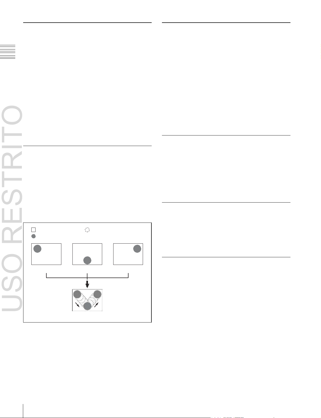
Keyframes
A keyframe represents an instantaneous state of an image;
it can be saved in a register and recalled for reuse. By
arranging a number of keyframes on the time axis, and
interpolating between successive keyframes, you can
create a “keyframe effect” in which there is a continuous
change from each keyframe to the next.
The following figure shows three keyframes created with
a wipe pattern (the circle) in different positions. This is
interpolated to create the effect shown.
Background A
Background B
Keyframe 1
Example of keyframes and effect execution
Keyframe 2
Execute effect
Interpolated images
Keyframe 3
You can save the sequence of keyframes representing a
single effect in a register. Then by recalling this register,
you can replay the same effect.
For details, see Chapter 12 “Keyframes”
(1 p. 239).
The term “snapshot” refers to a function whereby the
various settings required to apply a particular effect to an
image are saved in a register as a set of data, for recall as
required, to recover the original state.
Snapshots are divided as follows.
•
Snapshots applying to a particular region (functional
block of the switcher or DME)
•
Master snapshot
•
Key snapshot
•
Wipe snapshot
•
DME wipe snapshot
For details, see Chapter 13 “Snapshots”
(1 p. 267).
Utilities
The utility function refers to a function whereby you can
assign an arbitrary action or a shortcut for a frequently
used menu to a particular button, then instantly recall the
action or menu by pressing the button.
For details, see “Utility Execution”
14.
(1 p. 276) in chapter
Shotboxes
The term “shotbox” refers to a function whereby for each
specified region
(1 p. 239) any snapshot or keyframe
effect can be recalled simultaneously.
For details, see “Shotbox”
(1 p. 277) in chapter 14.
Macros
The term “macro” refers to the function whereby a
sequence of signal selections and other operations on the
control panel is saved as data in memory (macro register),
so that it can be recalled as required to automatically
execute the same sequence of operations.
The individual control panel operations constituting a
macro are termed “events.”
Macros also provide the following functions.
Menu macros
The term “menu macro” refers to the function whereby a
sequence of menu operations is saved as an event, so that
it can be recalled as required to automatically execute the
same sequence of operations.
Page 23

USO RESTRITO
Setup 23
Chapter
1
Overview
Macro timelines
By recording macro recalls and execute actions on a
timeline, in the same way as for keyframes in an effect,
you can automatically execute them in a sequence.
Macro attachments
Macro attachment is a function whereby a macro register
is assigned to a control panel button or a particular position
of a fader lever, linking the execution of the button
function or a fader lever operation with a macro execution.
Router/tally setup (Router/Tally)
For details, see Chapter 22 “Router Interface and Tally
Setup”
(1 p. 373).
User setup (User Setup)
For details, see Chapter 23 “User Setup”
(1 p. 378).
For details, see Chapter 15 “Macros”
(1 p. 281).
File Operations
You can save register data, including setup information
and snapshot information, as a file on a local disk or
removable disk, and recall it as required.
Regarding frame memory, it is possible to capture image
data stored in an external device into frame memory. You
can also convert the format of image data in frame memory
into a different format and save it in an external device.
For details, see Chapter 16 “Files”
(1 p. 302).
Setup
Various settings are required, in order to operate the
switcher, control panel, DME, external devices, and so on,
connected together in a single system.
This is referred to as “setup,” and you can carry out the
setup operations from the Engineering Setup menu
(hereinafter, the Setup menu). The settings are grouped
under the following headings.
System setup (System)
For details, see Chapter 17 “System Setup”
(1 p. 313).
Panel setup (Panel)
For details, see Chapter 18 “Control Panel Setup”
(1 p. 325).
Switcher setup (Switcher)
For details, see Chapter 19 “Switcher Setup”
(1 p. 345).
DME setup (DME)
For details, see Chapter 20 “DME Setup”
(1 p. 363).
DCU setup (DCU)
For details, see Chapter 21 “DCU Setup”
(1 p. 366).
Page 24
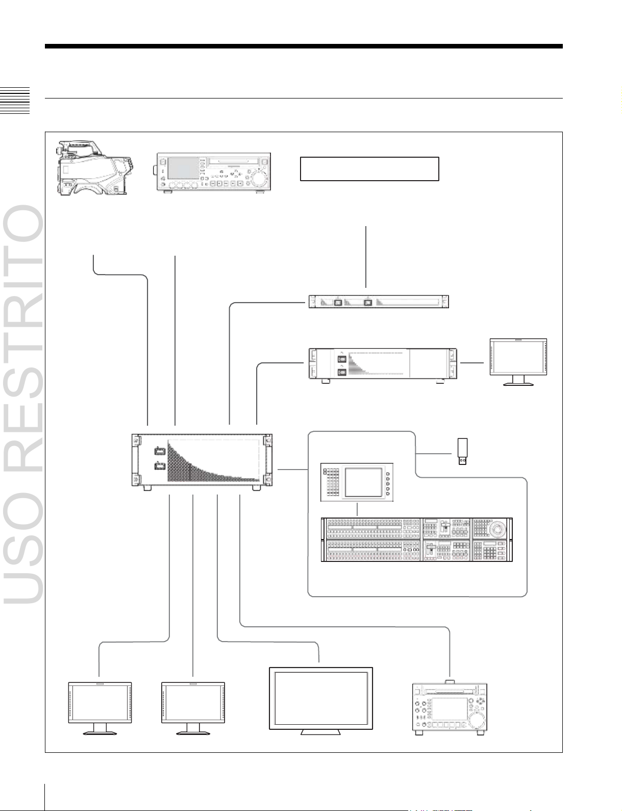
USO RESTRITO
24
System Configuration
Chapter
1
Overview
System Configuration
System Configuration Example
MVS-6520/6530/
3000A/3000 Multi
Format Switcher
Processor
ACCE
SS
NE
T
W
O
R
K
L
OC
AL
REMOTE
LEVEL
PHONES CH 1 CH 2 CH 3 CH 4
VARIABLE
F1
F
ME
2
ARK
NU
1
F
IN
3
F4 CHAPTE R
F5 EXPAND
SUB
THUMB
CLIP
NAIL
SET RESET
PAGE DISPLAY
CLIP ESSENCE
MENU MARK
SHIFT
PREV PLAY NEXT STOP REC SHUTTLE
KEY INHI
R
E
C
P
R
E
S
E
T
PB
TOP F REV F FWD END STANDBY
M
MARK2
EJECT
V
A
O
R
U
T
JOG
Audio mixer
Camera Playback VTR
MKS-2700/8700 Device Control Unit
POWER A
POWER B
MVE-8000A/9000
Multi Format DME Processor
ICP-6511
Menu Panel
ICP-6520/6530/3000/3016 Control Panel
Preview monitor Program monitor Monitor for multi viewer Recording VTR
a)
Menu can also be operated by connecting an external monitor in place of the menu panel.
b)
ICP-6520 diagram shown.
a)
DME monitor
Removable disk
b)
Page 25

USO RESTRITO
System Configuration 25
Chapter
1
Overview
Connection Example
MVS-6520/6530/3000A/3000 Multi Format Switcher Processor
MVS
ICP-6520/6530/3000/3016 Control Panel
MVS
a)
MVS-6520/3000A/3000 diagram shown.
b)
ICP-6520 diagram shown.
In addition to these devices, a DCU (MKS-8700/2700) or DME processor (MVE8000A/9000) can be used to extend the system.
AC power supplies
U
b)
DEVICE 1
DVI-D
DVI cable
USB cable
a)
ICP-6511 Menu Panel
AC power adaptor
LAN cable (straight type)
DVI-D
DEVICE
AC power
supplies
U
Page 26

USO RESTRITO
26
Names and Functions of Parts of the Control Panel
Chapter
2
Names
and
Functions
of
Parts
Name
ICP-6520 Control Panel
ICP-6530 Control Panel
ICP-3000 Control Panel
ICP-3016 Control Panel
Panel
configuration
Two rows
Three rows
Two rows
Two rows
Banks
M/E-1, PGM/PST
M/E-1, M/E-2, PGM/PST
M/E-1, PGM/PST
ME-1, PGM/PST
Keys
• When MVS-6520/
3000A/3000 (2M/E
processor) is
connected:
M/E-1: Key1 to Key4
P/P: DSK1 to DSK4
• When MVS-6530 (3M/E
processor) is
connected:
M/E-1: Key1 to Key4
P/P: DSK1 to DSK8
• When MVS-6520/
3000A/3000 (2M/E
processor) is
connected:
M/E-1: Key1 to Key4
P/P: DSK1 to DSK4
• When MVS-6530 (3M/
E processor) is
connected:
M/E-1, M/E-2: Key1 to
Key4
P/P: DSK1 to DSK8
• When MVS-6520/3000A/3000 (2M/E processor) is
connected:
M/E-1: Key1 to Key4
P/P: DSK1 to DSK4
• When MVS-6530 (3M/E processor) is connected:
M/E-1: Key1 to Key4
P/P: DSK1 to DSK8 (DSK5 to DSK8 insertion and
removal control from Flexi Pad)
Names and Functions of
Parts
Chapter
2
Names and Functions of Parts of the Control Panel
Specification differences for each system
configuration
In an MVS system, the number of available banks and keys
will differ depending on the control panel and switcher
processor configuration.
This manual describes operations and settings for an MVS6520/3000A and ICP-6520 configuration as an example.
For details about operational differences resulting from
different specifications, 1 “8-Keyer Operation” (p. 412).
Page 27
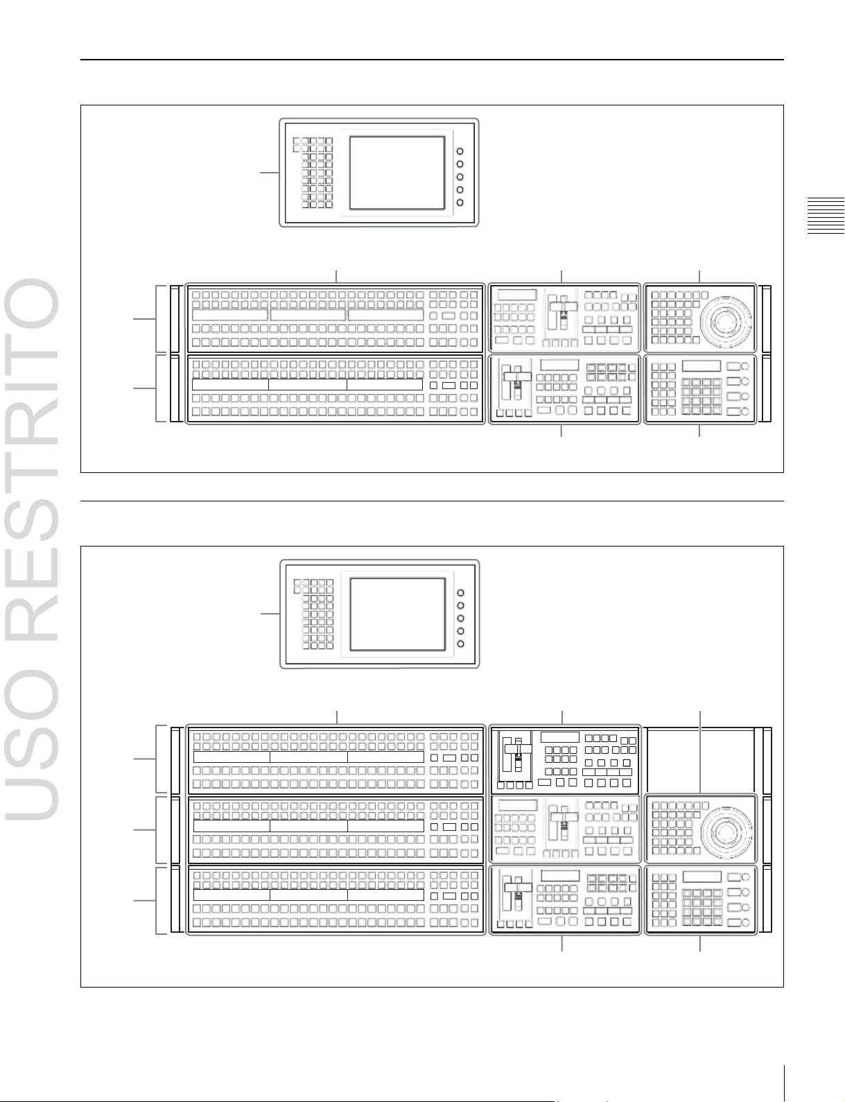
USO RESTRITO
Names and Functions of Parts of the Control Panel 27
Chapter
2
Names
and
Functions
of
Parts
ICP-6520 Control Panel Configuration
Menu panel
M/E-1
bank
PGM/PST
bank
(1
p. 42)
Cross-point control block (1 p. 29)
The menu panel is optional.
Transition control block
(M/E)
(1
p. 34)
Transition control block
(PGM/PST)
(1
p. 34)
Device control block
(1
Flexi Pad
p. 38)
(1
p. 40)
ICP-6530 Control Panel Configuration
Menu panel
M/E-1
bank
M/E-2
bank
PGM/PST
bank
(1
p. 42)
Cross-point control block
(1
p. 29)
The menu panel is optional.
Transition control block
(M/E)
(1
p. 34)
Transition control block
(PGM/PST)
(1
p. 34)
Device control block
(1
Flexi Pad
p. 38)
(1
p. 40)
Page 28
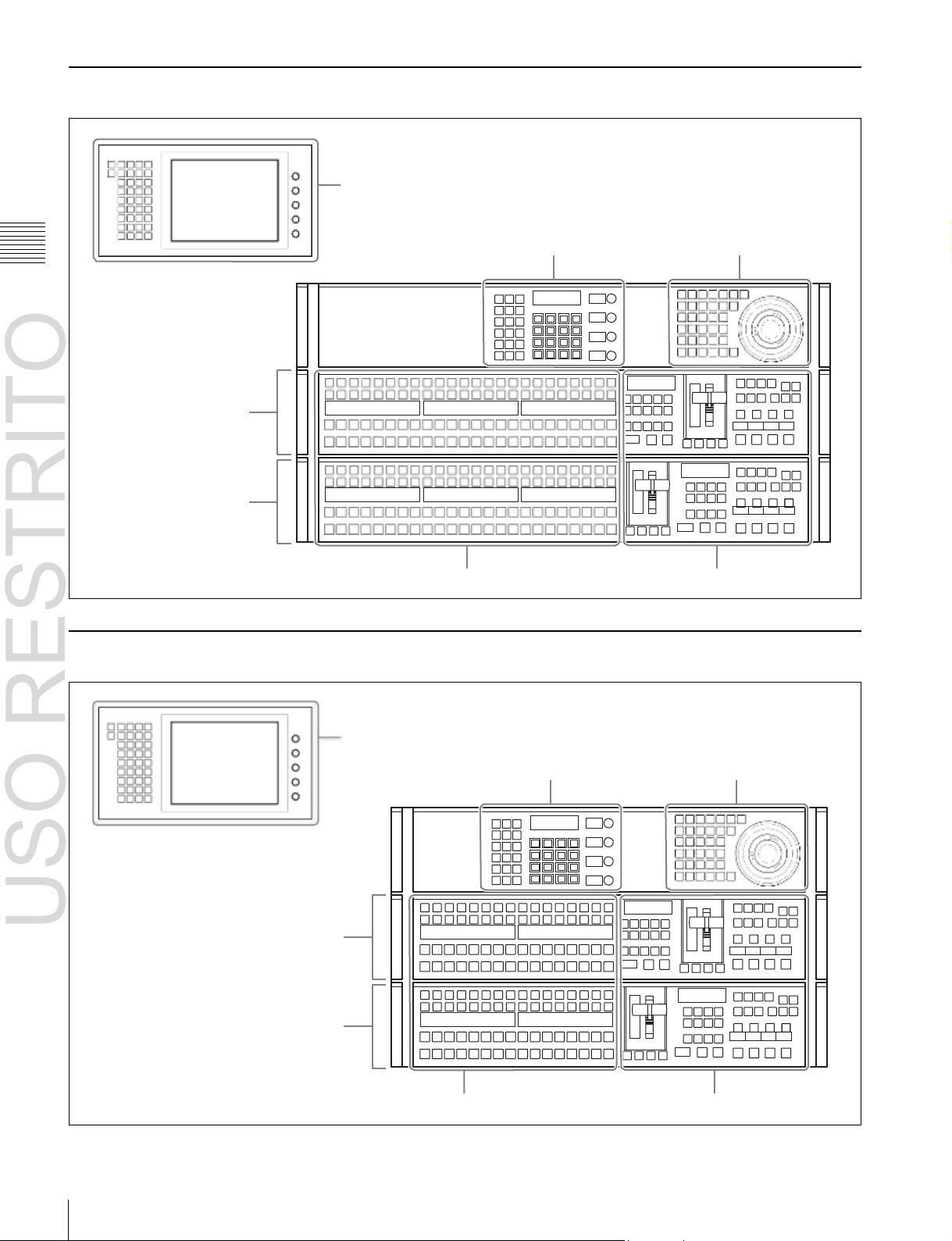
USO RESTRITO
28
Names and Functions of Parts of the Control Panel
Chapter
2
Names
and
Functions
of
Parts
ICP-3000 Control Panel Configuration
M/E-1 bank
PGM/PST bank
Menu panel
(1
p. 42)
Flexi Pad
Cross-point control block
(1
(1
p. 31)
p. 40)
The menu panel is optional.
Transition control block (1 p. 34)
Device control block
(1
p. 38)
ICP-3016 Control Panel Configuration
M/E-1 bank
PGM/PST bank
Menu panel
p. 42)
(1
Flexi Pad
Cross-point control block (1 p. 31)
(1
p. 40)
The menu panel is optional.
Transition control block (1 p. 34)
Device control block
(1
p. 38)
Page 29
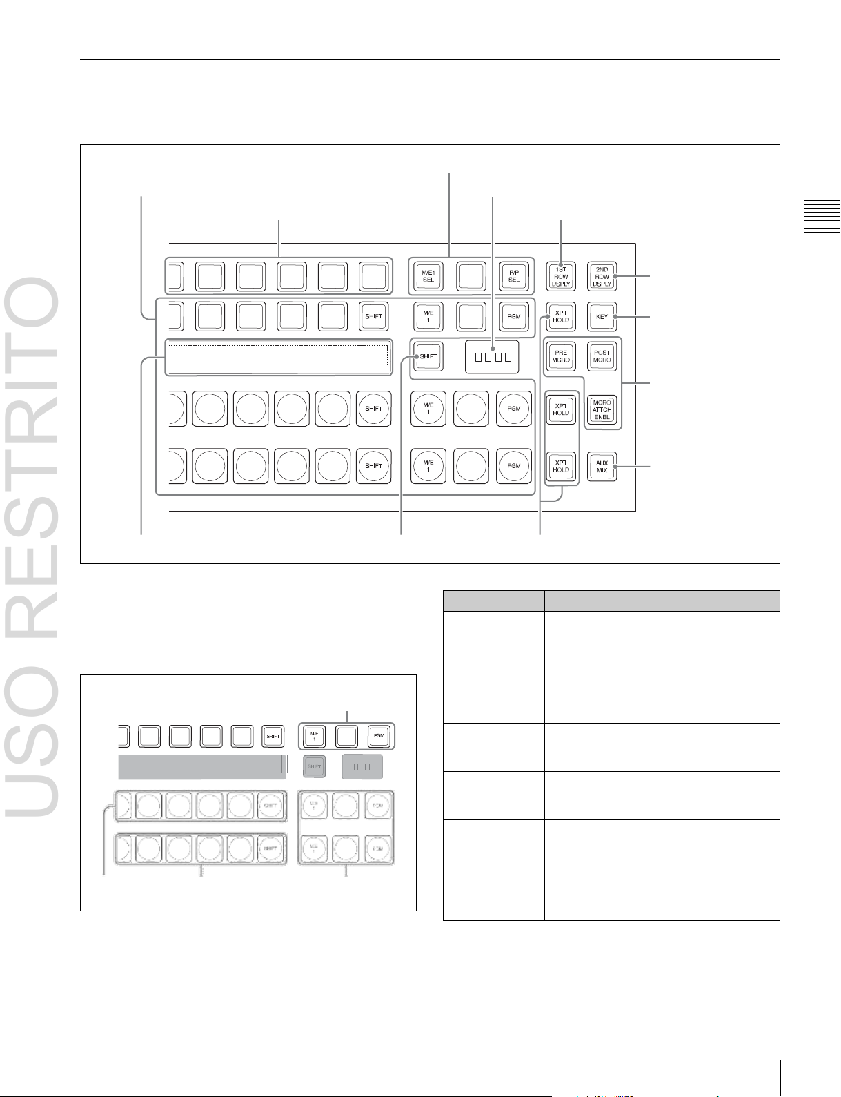
USO RESTRITO
Names and Functions of Parts of the Control Panel 29
Name
Description
2nd row
• Use this to select the cross-point of the
bus that is specified with the 1st row
buttons.
a) b)
• If the utility/shotbox function is selected
with the 1st row buttons, use this to
recall the register or to execute the
function.
Background A
row
Use this to select the signal as the
current background video on this M/E
bank or PGM/PST bank.
Background B
row
Use this to select the signal as the
background video after the transition on
this M/E bank or PGM/PST bank.
Reentry buttons
Use these to select the video created on
another bank as background A or B on
this bank or as the bus specified with the
1st row buttons.
For details, 1 “Selecting M/E reentry
input signals” (p. 60).
Chapter
2
Names
and
Functions
of
Parts
Cross-Point Control Block (ICP-6520/6530)
In the cross-point control block, you can select the signals
to be used in the M/E bank or PGM/PST bank.
a
Cross-point buttons
c
1st row
i
Source name displays
a
Cross-point buttons
These select the signals used for video processing on this
M/E bank or PGM/PST bank. Each row of buttons
corresponds to one or more signal buses within the
switcher.
2nd row
Reentry
buttons
e
M/E bank selection buttons
f
M/E bank display
d
Dedicated SHIFT button b XPT HOLD button
j
1ST ROW DSPLY button
k
2ND ROW DSPLY
button
l
KEY button
g
Macro buttons
h
AUX MIX button
Background
A row
Background
B row
Reentry
buttons
a) You can select the source signal of the key bus by selecting the cross-point
while holding down the button to which any of KEY1 to KEY4 or DSK1
to DSK4 is assigned in the 1st row.
b) You can select the image on the reverse side of the currently viewed DME
image by selecting the cross-point while holding down the button to which
any of DME1 V/K, DME2 V/K, or DME5 V/K to DME8 V/K is assigned
Page 30
USO RESTRITO
30
Names and Functions of Parts of the Control Panel
Name
Description
PRE MCRO
(pre-macro)
Sets a macro attachment in pre-macro
mode.
When setting to macro-only mode, this
button is used in combination with the
user preference button on the menu
panel with the “Macro Only Set”
assignment. This mode can also be set
by pressing the [PRE MCRO] and [POST
MCRO] buttons simultaneously.
POST MCRO
(post-macro)
Sets a macro attachment in post-macro
mode.
When setting to macro-only mode, this
button is used in combination with the
user preference button on the menu
panel with the “Macro Only Set”
assignment. This mode can also be set
by pressing the [PRE MCRO] and [POST
MCRO] buttons simultaneously.
Chapter
2
Names
and
Functions
of
Parts
in the 1st row (DME1 V/K and DME2 V/K using MKS-6570 only, and
DME5 V/K to DME8 V/K using MVE-8000A/9000 only).
Cross-point button numbers
Cross-point buttons and reentry buttons are respectively
numbered
(1 p. 61)
.
Assigning signals to buttons
You can assign a signal to each button using the Setup
menu.
For details, 1 “Cross-Point Settings” (p. 329).
Visual indications on cross-point buttons
For details, 1 “Colors of lit cross-point buttons” (p. 63).
b
XPT HOLD (cross-point hold) button
These allow you to recall a keyframe or snapshot while
keeping the current cross-point selection unchanged.
Functions for these buttons vary depending on the
operation mode selected in the Setup menu.
For details, 1 “Setting the operation mode of the key bus
[XPT HOLD] button” (p. 357).
c
1st row
This selects a key bus, AUX bus, or function.
You can assign the following buses, functions, and buttons
in the Setup menu.
•
KEY1 to KEY4, DSK1 to DSK4, UTIL1, EXT DME1),
EDIT PVW, AUX1 to AUX24, FMS1, FMS2,
DME1 V/K2), DME2 V/K2), DME5 V/K to
DME8 V/K
•
Utility/shotbox function
•
Inhibit Set function
•
Cross-point hold function
•
[PRE MCRO], [POST MCRO], [MCRO ATTCH
3)
ENBL], [KEY], [1ST ROW DSPLY], [2ND ROW
DSPLY], [SHIFT] buttons
1) MVS-6520/6530/3000A only
2) MKS-6570 only
3) MVE-8000A/9000 only
For details about assignments, 1 “Assigning a Bus or
Function to 1st Row Buttons” (p. 340).
Utility/shotbox function
Assign the function of the [UTIL/SBOX] button, and use
for utility/shotbox operations.
When you turn on the button to which [UTIL/SBOX] is
assigned, the buttons in the cross-point control block will
be used for utility/shotbox operations.
To inhibit an operation, press the cross-point button for
which you want to inhibit operation while holding the
button to which [INH SET] is assigned.
Cross-point hold function
Assign the function of the [XPT HOLD] button to recall a
keyframe or snapshot while maintaining the selection
status of the current cross-point.
Valid for background A row and B row. It can also be used
for the following function blocks when configured in the
Setup menu.
•
Background A row and B row
•
Key bus
•
Utility bus
•
DME external video bus (MVS-6520/6530/3000A only)
d
Dedicated SHIFT button
This button has the following two functions.
Source name display shift button: When this button is
enabled, the source name display shows the shifted
signal name.
Bus shift button: When this button is enabled, it acts as a
shift button for all buses on this M/E (PGM/PST)
bank.
You can select the mode in the Setup menu.
e
M/E bank selection buttons
These interchange the settings of the entire switcher bank
with the settings of the selected M/E bank.
This applies to all the buttons in the cross-point control
block and the transition control block.
f
M/E bank display
This indicates the notional mix/effect bank name to which
the particular M/E bank is assigned, as a four-character
identifier.
g
Macro buttons
These enable macro attachments and select the macro
attachment mode.
For details, 1 “Executing a Shotbox Function with
Cross-Point Buttons in the 2nd Row” (p. 280).
Inhibit Set function
Assign the function of the [INH SET] button, and use to
inhibit button operations.
Page 31

USO RESTRITO
Names and Functions of Parts of the Control Panel 31
Button name
Display
1ST ROW
DSPLY
2ND ROW
DSPLY
Off
Off
A/B bus signal names
On
Off
Bus names or function names
Off
On
Key/AUX bus signal names
a)
or
function names
Chapter
2
Names
and
Functions
of
Parts
Name
Description
MCRO ATTCH
ENBL (macro
attachment
enable)
Enables the macro attachments set for
the buttons of the M/E (PGM/PST) bank.
In the Setup menu, you can also set the
buttons to light whenever they are
enabled.
h
AUX MIX button
Executes an AUX mix transition when an AUX bus is
selected using the 1st row buttons.
For details about AUX mix transitions, 1 “AUX Mix
Transitions” (p. 78).
i
Source name displays
These show the names of the signals (sources) or registers
which can be selected on the cross-point buttons, in fourcharacter mode or auto mode.
While the [SHIFT] button on the right hand side or the
[SHIFT] button assigned to the cross-point button row is
enabled, the source name of the signal assigned to the
cross-point button in shift mode appears.
You can set the source name display mode in the Setup
menu.
The following displays may also appear, depending on the
status of the [1ST ROW DSPLY], [2ND ROW DSPLY],
and [KEY] buttons.
Cross-Point Control Block (ICP-3000/3016)
a) Key signal names are displayed when the [KEY] button is pressed, and
j
1ST ROW DSPLY button
When this is pressed and turned on, the bus names and
function names currently assigned to the 1st row appear in
the source name display.
k
2ND ROW DSPLY button
When this is pressed and turned on, the source name of the
bus currently selected in the 1st row appears in the source
name display. When the [UTIL/SBOX] button in the 1st
row is selected, function names are displayed.
l
KEY button
When you press a 2nd row button while holding down this
button, the key signal is selected.
video signal names are displayed when the [KEY] button is not pressed.
In the cross-point control block, you can select the signals
to be used in the M/E bank or PGM/PST bank.
a
Cross-point buttons
These select the signals used for video processing on this
M/E bank or PGM/PST bank. Each row of buttons
corresponds to one or more signal buses within the
switcher.
b
1st row
c
Source name displays
a
Cross-point buttons
Page 32

USO RESTRITO
32
Names and Functions of Parts of the Control Panel
Name
Description
2nd row
• Use this to select the cross-point of the
bus that is specified with the 1st row
buttons.
a) b)
• If the utility/shotbox function is selected
with the 1st row buttons, use this to
recall the register or to execute the
function.
Background A
row
Use this to select the signal as the
current background video on this M/E
bank or PGM/PST bank.
Background B
row
Use this to select the signal as the
background video after the transition on
this M/E bank or PGM/PST bank.
Name
Description
INH SET
(inhibit set)
Disables button operation.
To inhibit operation for a button,
press and hold the button
assigned with [INH SET], and
press the cross-point button
whose operation you wish to
inhibit.
XPT HOLD
(cross-point hold)
Recalls a keyframe or snapshot
while maintaining the current
cross-point selection conditions.
Available for background A row
and background B row.
The following function blocks can
be enabled, depending on
settings in the Setup menu.
• Background A and B rows
• Key bus
• Utility bus
• DME external video bus (MVS-
6520/6530/3000A only)
PRE MCRO
(pre-macro)
Sets a macro attachment in premacro mode.
When setting to macro-only mode,
this button is used in combination
with the user preference button on
the menu panel with the “Macro
Only Set” assignment. This mode
can also be set by pressing the
[PRE MCRO] and [POST MCRO]
buttons simultaneously.
POST MCRO
(post-macro)
Sets a macro attachment in postmacro mode.
When setting to macro-only mode,
this button is used in combination
with the user preference button on
the menu panel with the “Macro
Only Set” assignment. This mode
can also be set by pressing the
[PRE MCRO] and [POST MCRO]
buttons simultaneously.
Chapter
2
Names
and
Functions
of
Parts
2nd row
Background A row
Background B row
1) MVS-6520/6530/3000A only
2) MKS-6570 only
3) MVE-8000A/9000 only
For details about assignments, 1 “Assigning a Bus or
Function to 1st Row Buttons” (p. 340).
Utility/shotbox function
Assign the function of the [UTIL/SBOX] button, and use
for utility/shotbox operations.
When you turn on the button to which [UTIL/SBOX] is
assigned, the buttons in the cross-point control block will
be used for utility/shotbox operations.
a) You can select the source signal of the key bus by selecting the cross-point
while holding down the button to which any of KEY1 to KEY4 or DSK1
to DSK4 is assigned in the 1st row.
b) You can select the image on the reverse side of the currently viewed DME
image by selecting the cross-point while holding down the button to which
any of DME1 V/K, DME2 V/K, or DME5 V/K to DME8 V/K is assigned
in the 1st row (DME1 V/K and DME2 V/K using MKS-6570 only, and
DME5 V/K to DME8 V/K using MVE-8000A/9000 only).
Cross-point button numbers
Cross-point buttons are respectively numbered (1 p. 61)
Assigning signals to buttons
You can assign a signal to each button using the Setup
menu.
For details, 1 “Executing a Shotbox Function with
Cross-Point Buttons in the 2nd Row” (p. 280).
Assignable buttons
.
For details, 1 “Cross-Point Settings” (p. 329).
Visual indications on cross-point buttons
For details, 1 “Colors of lit cross-point buttons” (p. 63).
b
1st row
This selects a key bus, AUX bus, or function.
You can assign the following buses, functions, and buttons
in the Setup menu.
•
KEY1 to KEY4, DSK1 to DSK4, UTIL1, EXT DME1),
EDIT PVW, AUX1 to AUX24, FMS1, FMS2,
DME1 V/K2), DME2 V/K2), DME5 V/K to
DME8 V/K
•
Utility/shotbox function
•
[INH SET], [XPT HOLD], [PRE MCRO], [POST
3)
MCRO], [MCRO ATTCH ENBL], [KEY], [1ST ROW
DSPLY], [2ND ROW DSPLY], [SHIFT] buttons
Page 33

USO RESTRITO
Names and Functions of Parts of the Control Panel 33
Chapter
2
Names
and
Functions
of
Parts
Name
Description
MCRO ATTCH ENBL
(macro attachment
enable)
Enables the macro attachments
set for the buttons in the M/E
(PGM/PST) bank. In the Setup
menu, you can also set the
buttons to light whenever they are
enabled.
KEY
Pressing and holding this button
and then pressing a 2nd row
button selects the key signal.
1ST ROW DSPLY
(first row display)
Displays the name of the bus and
function currently assigned to the
1st row in the source name
display.
2ND ROW DSPLY
(second row display)
Displays the source name for the
bus currently selected in the 1st
row in the source name display. If
the [UTIL/SBOX] button is
selected in the 1st row, the
function name is displayed.
SHIFT
Performs one of the following
functions, according to the setting
made in the Setup menu.
• Source name display shift
button
Displays the name of the signal
in shift mode in the source
name display.
• Bus shift button
Functions as the shift button for
all busses in the M/E (PGM/
PST) bank.
Button name
Display
1ST ROW
DSPLY
2ND ROW
DSPLY
Off
Off
A/B bus signal names
On
Off
Bus names or function names
Off
On
Key/AUX bus signal names
a)
or
function names
c
Source name displays
These show the names of the signals (sources) or registers
which can be selected on the cross-point buttons, in fourcharacter mode or auto mode.
While the [SHIFT] button assigned to the 1st row or the
[SHIFT] button assigned to the cross-point button row is
enabled, the source name of the signal assigned to the
cross-point button in shift mode appears.
You can set the source name display mode in the Setup
menu.
The following displays may also appear, depending on the
status of the [1ST ROW DSPLY], [2ND ROW DSPLY],
and [KEY] buttons.
a) Key signal names are displayed when the [KEY] button is pressed, and
video signal names are displayed when the [KEY] button is not pressed.
Page 34

USO RESTRITO
34
Names and Functions of Parts of the Control Panel
Chapter
2
Names
and
Functions
of
Parts
Transition Control Block
In the transition control block, you can modify the output
of the M/E bank or PGM/PST bank, and perform
transitions. Both common transition and independent key
transition operations are possible.
6
PRIOR SET button
1
Next transition selection buttons
7
Key priority display
3
Transition execution
section
(ICP-6520/6530 M/E banks, ICP-3000/3016 M/E and PGM/PST banks)
2
Transition type selection buttons
4
Wipe direction selection buttons
Transition control block
5
TRANS PVW button
q;
Independent key transition type selection buttons
Shown above is the right-hand type transition control
block (with the right-hand fader lever).
9
Key delegation buttons
qs
K-SS STORE button
8
Independent key transition
execution section
qa
Key snapshot
buttons
Page 35

USO RESTRITO
Names and Functions of Parts of the Control Panel 35
Name
Description
BKGD
(background)
The next transition will change the
background.
KEY1 to KEY4
(DSK1 to DSK4
for the PGM/PST
bank)
• Press a button, turning it on, to make
the next transition insert or remove the
corresponding key (keys 1 to 4).
• If the key is currently not inserted, the
transition will insert it, and if the key is
currently inserted, the transition will
delete it.
For details about operations for keys 5 to
8, 1 “8-Keyer Operation” (p. 412).
KEY PRIOR
(priority)
The priority setting of the key after the
next transition is enabled.
ALL
This turns on a preselected set of the
[BKGD], [KEY1] to [KEY4], and [KEY
PRIOR] buttons. Make this setting in the
Setup menu.
Chapter
2
Names
and
Functions
of
Parts
6
PRIOR SET button
1
Next transition selection buttons
7
Key priority display
2
Transition type selection buttons
qd Independent key transition /
key snapshot control section
5
TRANS PVW button
3
Transition execution section
8
Independent key transition
execution section
4
Wipe direction selection buttons
a
Next transition selection buttons
These specify how the image will be changed as a result of
the next transition.
Transition control block (ICP-
6520/6530 PGM/PST bank)
b
Transition type selection buttons
These select the transition type
When multi-program mode is selected in the Setup menu,
two or more of the following buttons may light.
For details about the multi-program mode setting,
1
“Setting the Operation Mode” (p. 345).
You can also assign a function to these buttons that selects
whether or not the fader levers are used as keyframe
faders.
For details, 1 “Executing an effect manually” (p. 261).
For details about assignments for the transition type
selection buttons, 1 “Setting Transition Control Block
Button Assignments” (p. 327).
(1 p. 63).
Page 36

USO RESTRITO
36
Names and Functions of Parts of the Control Panel
Name
Description
NORM/REV
(normal/reverse)
The wipe direction alternates between
normal and reverse every time a
transition is executed.
Name
Description
Fader status
display
• Displays the transition progress as a
bar (transition indicator).
• In a non-sync state, “Non Sync” and
“Sync” appear at the top and bottom.
Fader lever
• Move this up or down to carry out the
transition.
• When you press the transition type
selection button to which the KF button
function has been assigned and turn it
on, you can use this as a keyframe
fader.
Transition rate
display
This shows the “transition rate” (the time
from the beginning of a transition to its
completion) set for an auto transition, in
frames.
AUTO TRANS
(transition)
button
• Pressing this button carries out an auto
transition of the set transition rate
(duration). The transition starts
immediately, and the button lights
amber.
• When the transition completes, the
button goes off.
CUT button
Pressing this button carries out the
transition as a cut (i.e. instantaneously).
Chapter
2
Names
and
Functions
of
Parts
c
Name
Description
NORM (normal)
The wipe proceeds in the direction from
black to white or in the direction of the
arrows as shown in “Wipe Pattern List”
(1
p. 381).
REV (reverse)
The wipe proceeds in the opposite
direction of [NORM].
Transition execution section
This section is used to carry out a transition and check the
progress of the transition.
Fader status display
Transition rate display
d
Wipe direction selection buttons
Fader lever
When a wipe or DME wipe is selected as the transition
type, you can press to light these buttons to select the wipe
direction.
e
TRANS PVW (transition preview) button
With the preview output of the M/E bank and PGM/PST
bank, you can check the effect of a transition in advance.
During the preview, you can use the fader lever, [AUTO
TRANS] button, and [CUT] button. One of the following
functions of this button can be selected in a Setup mode.
•
When the transition completes, the system returns to the
normal mode.
•
The transition preview mode is maintained while this
button is pressed.
•
Switching is made between the transition preview mode
and normal mode every time this button is pressed.
f
PRIOR (priority) SET button
While this button is held down, you can set the key
priority.
The setting mode when this button is pressed depends on
whether or not the [KEY PRIOR] button is lit, as follows.
•
When the [KEY PRIOR] button is off, the current key
priority is set.
•
When the [KEY PRIOR] button is lit, the key priority
after the next transition is set.
Press the [KEY PRIOR] button as required, to switch
between these two modes.
In either mode, hold down the [PRIOR SET] button, and
press the [KEY1] to [KEY4] ([DSK1] to [DSK4]) button
corresponding to the key you want to bring to the front.
For details, 1 “Setting the Key Priority in the Transition
Control Block” (p. 66).
g
Key priority display
The current key priority status is displayed on the left,
while the key priority status after the transition is displayed
on the right.
h
Independent key transition execution section
This is used to insert or delete keys 1 to 4, and carry out
auto transitions.
Page 37

USO RESTRITO
Names and Functions of Parts of the Control Panel 37
Name
Description
KEY1 ON to
KEY4 ON (DSK1
ON to DSK4 ON
for the PGM/PST
bank)
• Press the corresponding one of these
buttons to cut key 1 to key 4 in or out
instantaneously.
• The button lights red when the
corresponding key appears in the final
program output, and lights amber when
the key does not.
KEY1 TRANS to
KEY4 TRANS
(DSK1 TRANS
to DSK4 TRANS
for PGM/PST
banks)
Press these buttons to carry out an auto
transition.
Key source
name display
This displays the source name selected
on the corresponding keyer.
Name
Description
KEY TRANS
(key transition)
• The function of the LCD buttons
switches to independent key transition
type selection.
• Use the top row LCD buttons as key
delegation buttons for keys 1 to 4.
• Use the bottom row LCD buttons as
independent key transition type
selection buttons.
KEY SS (key
snapshot)
• The function of the LCD buttons
switches to key snapshot operation.
• Use the top row LCD buttons as key
delegation buttons for keys 1 to 4.
• Use the bottom row LCD buttons as
key snapshot buttons. You can save
key snapshots by pressing these
buttons while holding the [KEY SS]
button.
Chapter
2
Names
and
Functions
of
Parts
Key source
name display
Notes
For details about key 5 to 8 operations, 1 “8-Keyer
Operation” (p. 412).
i
Key delegation buttons
Assign the desired keyer, by pressing [KEY1] to [KEY4]
([DSK1] to [DSK4]) and turning them on.
While these buttons are held down, you can select a key
source with the cross-point buttons for the key bus.
Pressing one of these buttons twice in rapid succession
changes its state so that you can make cross-point
selections on the corresponding key bus.
The key delegation buttons can also be used for copying
keys.
For details, 1 “Copy and Swap Operations” (p. 149).
m
Independent key transition / key snapshot control
section
Selecting a function using the buttons on the right toggles
the function of the eight LCD buttons as follows.
KEY TRANS button
LCD buttons KEY SS button
Notes
Operation” (p. 412).
For details about key 5 to 8 operations, 1 “8-Keyer
j
Independent key transition type selection buttons
These select the independent key transition type.
For details, 1 “Basic Independent Key Transition
Operations” (p. 75).
k
Key snapshot buttons
These correspond to registers 1 to 4 of the keyer selected
with the key delegation buttons, and pressing a button
saves or recalls a key snapshot.
l
K-SS STORE (key snapshot store) button
Press the key snapshot button of the register you want to
save while holding this button to save the key snapshot.
Page 38

USO RESTRITO
38
Names and Functions of Parts of the Control Panel
Region
selection
button
Overview of assigned operation
FX CTRL
• This enables the Programmable Effector
software operation mode.
• The operation applies to the [FX1] to [FX4]
and [ID1] to [ID4] buttons.
For details, refer to the Help for the MPESFX01 Programmable Effector software.
Region
selection
button
Overview of assigned operation
M/E1, P/P
• These enable the positioner (wipe pattern
position setting) operation mode.
• You can select more than one button
simultaneously.
DME1,
DME2,
DME5 to
DME8
• These enable the three-dimensional
transform operation mode.
• You can select more than one button
simultaneously.
• The [DME1] and [DME2] buttons are
enabled only when using the MKS-6570.
• The [DME5] to [DME8] buttons are
enabled only when an MVE-8000A/MVE9000 is used.
DEV
• This enables the VTR/disk recorder/frame
memory operation mode.
• The operation applies to the [DEV1] to
[DEV12], [FM1 CLIP], [FM2 CLIP], and
[FM LOOP] buttons.
• You can also assign the [FM3 CLIP] to
[FM8 CLIP], [RECUE], and [LOOP]
buttons in the Setup menu.
RUN CTRL
This enables the keyframe operation mode.
RSZR CTRL
• This enables the resizer operation mode.
• Use the [M/E1] or [P/P] button to select the
target switcher bank.
• The operation applies to the [K1RSZ] and
[K2RSZ] buttons.
Chapter
2
Names
and
Functions
of
Parts
Device Control Block
Name
Description
K1 to K4
a) b)
These enable wipe pattern position setting
for keys 1 to 4.
WIPE
a)
This enables wipe pattern position setting for
normal transitions.
POS
(position)
This enables the trackball to move the wipe
pattern in the X-axis and Y-axis directions.
X, Y
These restrict which axes the trackball can
control to the X- or Y-axis.
CTR (center)
This returns the pattern position to the center
of the screen.
CLR WORK
BUFR (clear
work buffer)
Press this twice in rapid succession to reset
all parameters on the target M/E or PGM/
PST to their initial values.
The device control block is used for three-dimensional
transform operations using a DME, for wipe pattern
1
Region selection
buttons
5
MENU button
2
Operation buttons
a
Region selection buttons
The operation mode allocated to the device control block
depends on the selection state of the region selection
buttons.
position setting, and for VTR/disk recorder/frame memory
clip operation.
3
Trackball
4
Z-ring
b
Operation buttons
These perform various operations. The function of each
button varies with the operation mode.
When the positioner operation mode is enabled
a) You can configure settings in the Setup menu to allow simultaneous
selection of multiple buttons.
b) For details about operations for keys 5 to 8, 1 “8-Keyer Operation”
(p. 412).
Page 39

USO RESTRITO
Names and Functions of Parts of the Control Panel 39
Name
Description
CTR (center)
• Pressing this button once changes the
two-dimensional transformation and
rotation settings to the closest detent
values.
• Pressing the [CTR] button twice, or holding
down [SHIFT] and pressing the [CTR]
button returns the two-dimensional
transformation and rotation settings to the
defaults.
SHIFT
Use this in combination with the [CTR
WORK BUFR] or [CTR] button.
Name
Description
LOC SIZE
(ASP:
aspect)
• Pressing this button and operating the
trackball or Z-ring changes the aspect ratio
of a key to which the resizer function is
applied.
• When this button is held down, the
trackball or Z-ring operation is switched to
a finer control (fine mode).
LOC XYZ
(LOC:
location)
• Pressing this button and operating the
trackball or Z-ring moves, shrinks, or
magnifies a key to which the resizer
function is applied.
• When this button is held down, the
trackball or Z-ring operation is switched to
a finer control (fine mode).
ROT (RSZR:
resizer)
Press this button, turning it on, to enable the
resizer.
ASP PERS
(ROT:
rotation)
• Pressing this button, after pressing the
[RENB] button, and operating the trackball
or Z-ring rotates the key to which the
resizer function is applied or adjusts
perspective.
• When this button is held down, the
trackball or Z-ring operation is switched to
a finer control (fine mode).
AXIS (RENB:
rotation
enable)
Press this button, turning it on, to enable
rotation operation.
CLR WORK
BUFR (clear
work buffer)
• Pressing this button once returns the twodimensional transformation and rotation
settings to the defaults.
• Pressing the [CLR WORK BUFR] button
twice, or holding down [SHIFT] and
pressing the [CLR WORK BUFR] button
returns all resizer parameter values to the
defaults.
X, Y, Z
These restrict the axes affected by the
trackball and Z-ring to the X-, Y- or Z-axis.
Chapter
2
Names
and
Functions
of
Parts
When the three-dimensional transform operation
mode is enabled
The buttons are used for three-dimensional DME
transformations.
For details, 1 “Three-Dimensional Transformation
Operations” (p. 169).
When the VTR/disk recorder/frame memory
operation mode is enabled
The buttons are used for VTR control or playback of frame
memory clips.
For details, 1 “Controlling the Tape/Disk Transport”
(p. 230).
When the resizer operation mode is enabled
c
Trackball
The effect of operation depends on the operating mode as
follows.
When the positioner operation mode is enabled
By moving this, you can move the pattern in the X-axis and
Y-axis directions.
When the three-dimensional transform operation
mode is enabled
Move the trackball to control three-dimensional transform
operation of the X- and Y-axes.
When the [SRC] or [TRGT] button is held down, the
operation is switched to a finer control (fine mode).
When the resizer operation mode is enabled
By turning the trackball, you can move in the X and Y
directions of the key to which the resizer is applied, change
the aspect ratio, and rotate around the X-axis and Y-axis.
When the [LOC SIZE], [LOC XYZ], or [ASP PERS]
button is held down, the operation is switched to a finer
control (fine mode).
d
Z-ring
The effect of operation depends on the operating mode as
follows.
When the three-dimensional transform operation
mode is enabled
Turn this ring to control three-dimensional transform
operation of the Z-axis.
When the [SRC] or [TRGT] button is held down, the
operation is switched to a finer control (fine mode).
When the keyframe operation mode is enabled
By turning the Z-ring, you can run the keyframe effect,
independent of the STOP NEXT KF, EFFECT LOOP, and
similar settings in the Flexi Pad.
Turn clockwise to run the effect in the normal direction,
and counterclockwise for the reverse direction.
Page 40

USO RESTRITO
40
Names and Functions of Parts of the Control Panel
Name
Description
TRANS RATE
(transition rate)
Press this to set the transition rate.
KEY ADJ (key
adjust)
Press this to carry out key adjustments
and set modifiers.
KEY SS (key
snapshot)
Press this to carry out key snapshot
creation/recall/deletion.
By default, this is not assigned to a mode
selection button, so you must assign it to
a mode selection button in the Setup
menu before use.
Chapter
2
Names
and
Functions
of
Parts
When the VTR/disk recorder/frame memory
Name
Description
EFF (effect)
Press this to carry out effect creation/
recall/editing/execution/deletion.
SNAPSHOT
Press this to carry out snapshot creation/
recall/editing/deletion.
SHOTBOX
Press this to carry out shotbox creation/
recall/editing/execution/deletion.
MCRO (macro)
Press this to carry out macro creation/
editing/execution/deletion.
WIPE (wipe
snapshot)
Press this to carry out wipe snapshot
creation/recall/deletion and wipe
adjustments.
DME WIPE
(DME wipe
snapshot)
Press this to carry out DME wipe
snapshot creation/recall/deletion and
DME wipe adjustments.
operation mode is enabled
Turning the Z-ring controls the tape transport/disk drive/
frame memory clip operations, at a speed determined by
the operating buttons. Turn clockwise for the normal
direction, and counterclockwise for the reverse direction.
When the resizer operation mode is enabled
By turning the ring, you can zoom the key to which the
resizer is applied, and change the aspect ratio and
perspective.
When the [LOC SIZE], [LOC XYZ], or [ASP PERS]
button is held down, the operation is switched to a finer
control (fine mode).
e
MENU button
This enables adjustment of the menu parameters using the
trackball and Z-ring.
In the case of the DME menu, the operation applies to the
selected DME channel.
Pressing this button and turning it on in VTR/disk
recorder/frame memory operation mode makes it possible
to carry out timeline start/stop point setting operation for
the selected device (timeline setting mode).
Flexi Pad
The Flexi Pad is used for creating and recalling snapshots,
wipe snapshots, DME wipe snapshots, key snapshots,
1
Mode selection
buttons
2
EDIT ENBL button
3
Region selection
buttons
5
Memory recall section
a
Mode selection buttons
These select the mode.
effects, shotboxes, and macros, for setting the transition
rate, and for adjusting keys.
4
Alphanumeric display
7
6
Adjustment knobs
Adjustment
knob displays
Page 41

USO RESTRITO
Names and Functions of Parts of the Control Panel 41
Chapter
2
Names
and
Functions
of
Parts
b
Name
Description
ALL
• Selects all regions.
• If any region is selected, press this
button to unset the selection of all
regions.
DME1 to DME2
• Select a DME channel.
• The [DME1] and [DME2] buttons are
enabled only when using the MKS-
6570.
M/E1, P/P
Select the M/E-1 and PGM/PST regions,
respectively.
USER4
Selects the USER4 region.
DEV1
Selects the device 1 region.
MORE
• Displays buttons in the memory recall
section for regions not assigned to a
region selection button, so that they
can be selected.
• By default the following regions are
shown on the memory recall section
buttons:
MSTR (master snapshot, master
timeline registers), USER1 to 3,
USER5 to 8, MCRO (macro), DEV2
(device 2), PBUS, GPI, RTR (router)
• If there is a region selected in the
memory recall section, this is indicated
by the [MORE] button lighting green.
• To revert the button displays in the
memory recall section, press the
[MORE] button once more, or press the
[EXIT] button that appears in the
memory recall section.
• Note that except for the [ALL], [EXIT],
and [MORE] buttons, you can freely
change the region assignments in the
Setup menu.
EDIT ENBL (edit enable) button
This enables the following operations.
•
Effect creation/editing
•
Snapshot attribute setting
•
Shotbox creation/editing
•
Macro creation/editing
•
Wipe adjustments
•
DME wipe adjustments
c
Region selection buttons
These select the functional block (“region”) of the control
panel to which operations apply.
When the [EFF], [SNAPSHOT], [SHOTBOX], or
[MCRO] mode selection button is selected, you can select
multiple region selection buttons simultaneously. In this
case, the first button pressed lights green as the reference
region, and the other buttons pressed light amber (the
buttons for the regions shown in the memory recall section
are yellow).
d
Alphanumeric display
This shows the selected region name, register number, and
entered numeric values.
e
Memory recall section
This comprises 16 LCD buttons, each with a display that
changes according to the operating mode.
f
Adjustment knob displays
Each of these shows the initial letter of the parameter that
value (three digit places, including the minus sign).
g
Adjustment knobs
Use these to adjust the parameters selected with the
memory recall section buttons.
can be adjusted with the knob to the right, and the setting
Page 42

USO RESTRITO
42
Names and Functions of Parts of the Control Panel
Chapter
2
Names
and
Functions
of
Parts
Menu Panel
Connect an optional ICP-6511 menu panel, and use it for
menu operations.
1
Top menu selection buttons
2
Menu display
d
User preference buttons
These recall the functions or menus assigned to them in the
Setup menu.
It is also possible to change the assignment of these buttons
in the Setup menu.
For details, 1 “Assigning Functions to User Preference
Buttons” (p. 334).
4
User preference buttons
3
a
Top menu selection buttons
Adjustment knobs
These select the menu appearing in the menu display.
It is also possible to change the assignment of these buttons
in the Setup menu.
For details, 1 “Assigning Functions to the Menu Panel
Top Menu and User Preference Buttons” (p. 328).
b
Menu display
This shows the menu currently in use.
c
Adjustment knobs
These adjust the parameter values appearing in the menu.
Page 43

USO RESTRITO
Names and Functions of Parts of the Menu 43
Chapter
2
Names
and
Functions
of
Parts
Names and Functions of Parts of the Menu
Overview
In the MVS system, all detailed settings for basic
operations such as transitions, keys, and wipes, and DME
are made in menus. In addition, system management, data
management, and setup are all performed using menu
operations.
Top Menu List
When the control panel is powered on, the top menu list
appears as shown below.
Use the optional ICP-6511 menu panel to perform menu
operations. You can also display menus on an external
For information about using the mouse,
with a Mouse” (p. 51).
For information about supported monitors, contact your
Sony representative.
In the same way as for the top menu selection buttons on
the menu panel, press each button to display the
corresponding top menu in the menu display.
Press [Shutdown] on the bottom right to shut down the
control panel.
For details about shutting down the control panel,
1
“Shutting down the control panel” (p. 56).
Notes
1
“Operation
monitor, and operate using a mouse or touch panel.
•
The arrangement of buttons in the top menu list and the
default arrangement of the top menu selection buttons
may be different.
•
Changing the top menu selection button assignment in
the Setup menu has no effect on the top menu list.
Menu Screen
The menu screen consists of the following principal parts.
The section describes the M/E-1 >Key1 >Type menu
(1111) screen as an example.
Page 44

USO RESTRITO
44
Names and Functions of Parts of the Menu
Chapter
2
Names
and
Functions
of
Parts
qs
b
(previous) button and B (next) button
5
Status area
2
Menu page number button
1
Menu title button
qa
Default recall button
3
VF buttons
a
Menu title button
This shows the title of the menu screen.
You can set different colors for the main menu site and
subsidiary menu site
(1 p. 52).
b
Menu page number button
This shows the menu screen page number.
When you press this button, the top menu window
(1 p. 46) appears. You can enter the page number for the
desired menu, or press one of the top menu selection
buttons in the window, to display that menu.
While the system is accessing the local disk or external
HDD, the indicator lights red.
Indicator for frame memory external
HDD
Local disk indicator
4
HF buttons
9
Previous page button
8
Parameter setting buttons
6
Function button area
7
Parameter group button
0
Keyframe status
Notes
When the indicator is lit, do not turn the power to the
switcher OFF or disconnect the USB cable1).
1) When an external HDD is connected
c
VF buttons
These indicate the larger subdivisions (2nd level) of the
menu.
Depending on the selected item, the menu screen contents
change, including the HF button indications.
d
HF buttons
These indicate the smaller subdivisions (3rd level) of the
menu.
Depending on the selected item, the menu indications
change.
Functions that are enabled are indicated by an orange bar
in the VF and HF buttons.
Page 45

USO RESTRITO
Names and Functions of Parts of the Menu 45
Chapter
2
Names
and
Functions
of
Parts
Color
State
Pale blue
The function is enabled, and the
parameters can currently be
adjusted.
Orange
The function is enabled.
Purple
Execution button. Pressing the
button immediately executes the
function.
(Example: [Auto Start] in the
Chroma Adjust menu)
e
Status area
This shows the status of the settings items controlled by the
selected menu.
An orange frame appears around the parameter area
relating to the displayed menu. For each of the 12 areas,
pressing the display jumps to the related menu.
f
Function button area
This shows the functions that can be operated in the
currently selected menu by means of buttons.
Each function button corresponds to a function which can
be set in the currently selected menu. Press a button to
enable the function, display a parameter group and adjust
the parameters, or execute the function.
These buttons are grouped by function. In the screen
example, the [Key Bus] and [Matte] function buttons
constitute the <Key Fill> group.
Pressing a button turns it on and lights it, showing the state.
i
Previous page button
This shows the page number of the previously displayed
menu screen. Press it to go back to that page.
j
Keyframe status
This shows the keyframe status of the reference region.
Pressing this button switches the menu screen as follows.
When a menu other than the Key Frame menu is
currently shown: The menu screen switches to the
Key
Frame menu.
When the Key Frame menu is currently shown: The
menu screen switches to the menu that was on the
screen immediately before the Key Frame menu.
In some menus, such as the File menu, this functions as a
“Region selection area” for selecting the region to which
operations apply.
k
Default recall button
Press this button, and then press a VF button or parameter
setting button to return the parameters to their default
values, in the following groupings.
•
Function grouping (functions of the HF buttons under
the VF button)
•
Parameter grouping (values of the parameter setting
buttons)
This only appears in those menus for which the default
recall function is available.
When you press a function button that is
in this state, another menu appears.
(Example: [Chroma Adjust] in the Type
menu)
g
Parameter group button
This displays parameter group names for adjustments, the
current parameter setting page number, and the total
number of the parameter setting pages (Example: Color
Vector 1/2).
When there are more than five parameters within the same
parameter group, press this button to display the sixth and
subsequent parameters, which can then be controlled.
h
Parameter setting buttons
These show the parameters and their values. Pressing one
of these buttons displays the numeric keypad window
(1 p. 47), and you can then enter a new value for the
corresponding parameter with the numeric keypad.
For details about menus that can be returned to their
default states, 1 “Menu Tree” (p. 386).
l
b (previous) button and B (next) button
The b button returns to the previous menu. Press the B
button to continue to the next menu.
Page 46

USO RESTRITO
46
Names and Functions of Parts of the Menu
Chapter
2
Names
and
Functions
of
Parts
Top Menu Window
a
Top menu selection buttons
These display the selected menu.
b
[Shutdown] button
Shuts down the control panel.
1
Top menu selection buttons
2
[Shutdown] button
3
[Add Favorite] button
4
[Close] button
5
Page number entry section
For details about shutting down the control panel,
1
“Shutting down the control panel” (p. 56).
c
[Add Favorite] button
This registers the currently displayed menu to the Shortcut
menu
(1 p. 51)
.
d
[Close] button
This closes the top menu window.
e
Page number entry section
Enter a page number and press [Enter] to open that page. If
the page number does not exist, the color of the entered
page will change. Pressing [Clear] clears the entry.
Page 47

USO RESTRITO
Names and Functions of Parts of the Menu 47
Chapter
2
Names
and
Functions
of
Parts
Numeric Keypad Window
1
Item display
2
Max./min. value
indication
3
Input display
4
[Close] button
5
TC (timecode) button
6
– (minus) button
7
a
Item display
This is the name of the parameter being set in the numeric
keypad window.
b
Max./min. (maximum/minimum) value indication
This shows the maximum and minimum values of the
parameter.
c
Input display
This is the value being input into the numeric keypad
window.
d
[Close] button
This closes the numeric keypad window.
e
TC (timecode) button
When the numeric keypad window is opened for a setting
requiring a timecode value to be entered, this button
appears in a depressed state.
The range of timecode values you can enter varies as
follows depending on the signal format.
00:00:00:00 to 23:59:59:nn,
where nn = (number of frames per second) – 1.
f
– (minus) button
This toggles the sign of the entered value.
g
[Clear] button
This clears the input display. It does not change the
parameter setting.
[Clear] button
8
[Trim] button
9
[Enter] button
h
[Trim] button
After entering the difference from the current value, press
this button to confirm the numeric input.
i
[Enter] button
This confirms the entered value.
If correctly set, the numeric keypad window closes.
If it is not correctly set, the input display changes color.
Page 48

USO RESTRITO
48
Names and Functions of Parts of the Menu
Chapter
2
Names
and
Functions
of
Parts
Keyboard Window
Notes
Except when changing source names, the following
characters cannot be used.
space, \, /, :, ;, , (comma), . (dot), <, >, *, ?, ", |
1
Item display
5
[Caps Lock] button
6
[Shift] button
7
[Space] button
8
[Clear] button
a
Item display
This is the name of the parameter being set.
b
Input display
This is the character string being input.
c
[Close] button
This closes the keyboard window.
d
[BS] (backspace) button
This clears the character immediately before the cursor.
e
[Caps Lock] button
This enables input of capital letters only.
Notes
You can enter items to be displayed on the control panel
LCD using lowercase letters, but these will be converted to
capitals for display.
MS-DOS does not distinguish case in filenames, and
therefore you are recommended to enter filenames in
capital letters.
f
[Shift] button
This selects the characters on the shift side of the keys. The
shift is released when you enter a character.
2
Input display
g
[Space] button
9
[Del] button
[Close] button
4
[BS] button
qs
Line feed button
qa
[Enter] button
0
[Left]/[Right]
button
3
This enters a space character.
h
[Clear] button
This clears all of the characters in the input string.
i
[Del] (delete) button
This clears the character immediately after the cursor.
j
[Left]/[Right] button
These move the cursor one character to the left or right in
the input string.
k
[Enter] button
This sets the input string as a parameter value.
If correctly set, the keyboard window closes. If it is not
correctly set, the input display changes color.
l
Line feed button
input display shows this as “|”.
After pressing [Shift], press this button to feed a line. The
Page 49

USO RESTRITO
Basic Menu Operations 49
Chapter
2
Names
and
Functions
of
Parts
Color Palette Window
When parameters are assigned as a combination of
luminance, saturation, and hue, pressing a parameter
setting button displays a color palette window.
1
Color palette buttons
2
Operation buttons
3
Color display
4
Numeric keypad
a
Color palette buttons
Press one of these to display the corresponding color in the
color display.
b
Operation buttons
Set: If you press any color palette button with this button
held down, the color shown in the color display is
assigned to the color palette button.
Copy: If you press a color palette button with this button
held down, the color is used as the source for copying.
Next press a different color palette button to copy to
that button.
Swap: If you press two color palette buttons in sequence
with this button held down, the two colors are
swapped.
Default: If you press any color palette button with this
button held down, the color palette button is set to the
default color.
c
Color display
This shows the setting color and its parameters (LUM,
SAT, and HUE).
By adjusting the parameters, you can create any color.
If a parameter value is outside the permitted range for RGB
(0 to 255), the “Illegal Color” indication appears, and this
is adjusted to a value within range.
Cancel: Pressing this button returns to the state when the
color palette window was opened.
d
Numeric keypad
Use this to enter numeric values for parameters.
For details, 1 “Numeric Keypad Window” (p. 47).
Basic Menu Operations
Notes
Some menus may not be displayed depending on the
system configuration.
Some functions and items not supported by the MVS6520, MVS-3000A, or MVS-3000 may be displayed in
parts of the menu. These items are ignored, even if selected
and values specified, and are not reflected in the system
operation.
For details, 1 “Menus of Disabled Operations and
Settings” (p. 405).
Recalling Menus
The following three methods are available for recalling
menus.
Page 50

USO RESTRITO
50
Basic Menu Operations
No.
Parameter
Adjustment
1
Size
Pattern size
2
Soft
Edge softness
3
Density
Key density
Chapter
2
Names
and
Functions
of
Parts
No.
Parameter
Adjustment
1
No
Select folder
2
Num
Number to select
Top menu selection buttons on the menu panel
Open the top menu (1st menu level) of the corresponding
menu for each button.
Top menu window
Specify the menu page number to open the menu. In the
same way as the menu panel, you can also open top menus
using the top menu selection buttons.
For details, 1 “Top Menu Window” (p. 46).
Pressing a particular button twice
Open the menu that corresponds to the button.
Example: Selecting frame memory folders
If the [No] parameter is set to “2” and the [Num] parameter
is set to “5,” five folders are selected starting from folder
number 2.
Setting Parameters
For details, 1 “Menu Access by Pressing a Button
Twice” (p. 417).
Selecting Menus
1
Display the top menu.
2
Use the VF buttons (right side of screen) to select the
2nd level of the menu, and then use the HF buttons
(bottom of screen) to select the 3rd level of the menu.
3
Press the appropriate function button within the
function button area (center of screen).
In this manual, menu selection operations are indicated as
“1st level >2nd level >3rd level (menu number).”
Example: To select the Shortcut menu
Home >Favorites >Shortcut menu (0021)
To go back to the previous menu
To return to the last displayed menu, press the previous
page button.
The above mark on a function button indicates that there
are parameters which can be adjusted.
When you press such a button, you can set the parameters
mark
using one of the following methods.
•
Turn the knob corresponding to the parameter to adjust
the value.
•
Press the parameter setting button corresponding to the
parameter. This displays the numeric keypad window
allowing you to enter the desired value.
•
Operation using the mouse
(1 p. 51).
In this manual, the parameter setting operation is described
as shown below.
The “No.” column indicates the menu panel adjustment
knob and parameter setting button position (1 to 5 from the
top).
Example: To set the key wipe pattern key parameters
Selecting List Items
The following methods can be used to select items
displayed in lists on the menu screens.
•
Press an item in the list directly.
•
Press the arrow keys to scroll to highlight the item.
•
Turn the knob corresponding to the item selection
parameter.
•
Press the parameter settings button for the item
selection, and enter the item number in the numeric
keypad window.
Depending on the menu, you can click [Plural] to select
multiple items or [All] to select all items.
You can also select the number of parameters using
[Num].
You adjust the [Size] parameter (pattern size) using the
first adjustment knob or the first parameter setting button.
In addition, when the [MENU] button in the device control
block is pressed and turned on, you can use the trackball
and Z-ring to adjust the parameters.
•
Move the trackball on the X-axis to adjust the first
parameter, and on the Y-axis to adjust the second
parameter. Moving up or to the right increases the
parameter value, and moving down or to the left
decreases the parameter value.
•
Turn the Z-ring to adjust the third parameter.
Turning clockwise increases the parameter value, and
turning counterclockwise decreases the parameter value.
Page 51

USO RESTRITO
Basic Menu Operations 51
Chapter
2
Names
and
Functions
of
Parts
Returning Parameters to Default
Values
Press the [Default Recall] button, turning it on, then press
a VF button or parameter setting button to return the
parameters to their default values, in the following
groupings.
•
When a VF button is pressed: Function grouping
(functions of the HF buttons at the bottom of the screen)
•
When a parameter setting button is pressed: Parameter
grouping
Notes
•
The default state of the parameters depends on the initial
status mode specified in the Setup menu, as follows.
User: The state when [Initial Status Define] is executed.
Factory: Factory default settings
•
The horizontal (H) and vertical (V) position settings
cannot be returned to their default states individually.
For example, returning the horizontal (H) position to its
default value also returns the vertical (V) position to its
default value automatically, and vice versa.
For details about menus that can be returned to their
default states, 1 “Menu Tree” (p. 386).
In the Setup menu, you can specify the scroll direction and
whether parameters increase or decrease in relation to the
mouse wheel rotation. You can also switch the functions of
the right and left mouse buttons during parameter setting
button adjustments.
For details, 1 “Setting the Mouse Wheel Scrolling
Direction for Parameter Setting” (p. 344) and
1
“Selecting the Mouse Button for the Parameter Setting
Buttons” (p. 344).
Using Shortcut Menus
Create a shortcut menu by grouping frequently used menus
into a “Favorites” menu.
In addition to menus, menu macros can also be saved to the
shortcut menu.
For details about menu macros, 1 “Menu Macros”
(p. 295).
The shortcut menu settings are handled as part of the
control panel setup. You can recall and save them in the
same way as setup data.
Recalling a menu from the shortcut menu
1 Open the Home >Favorites >Shortcut menu (0021).
Operation with a Mouse
Instead of pressing buttons on screen (touch operation),
you can position the mouse cursor over a button and click
the mouse. The parameter setting and list scrolling
operations are described below.
To set a parameter with the mouse
To adjust the value of a parameter setting button with the
mouse, you can use one of the following three methods.
•
Position the cursor over the parameter setting button for
which you want to adjust the value, and turn the mouse
wheel.
•
Position the cursor over the parameter setting button for
which you want to adjust the value, then hold down the
right mouse button, and drag the bar showing the setting
to the desired value.
•
Position the cursor over the parameter setting button for
which you want to adjust the value, then click the left
mouse button to open the numeric keypad window and
enter the desired value.
To scroll a list with the mouse
Position the cursor over the list you want to scroll, and turn
the mouse wheel.
2
Select a group in the <Group Select> group.
3
Press the button to which the desired menu is
registered.
Registering a menu to the shortcut menu
You can register 15 buttons to a single shortcut menu
group. The following two registration methods are
available.
To register by page number
1
In the Home >Favorites >Shortcut menu (0021), select
the group to which you want to register the menu.
2
Press [Button Edit].
The Home >Favorites >Button Edit menu (0023)
appears.
3
Select the position in which to display the button.
To change the content of an already displayed button,
press the button to select it.
4
Press [Page Set].
Page 52

USO RESTRITO
52
Basic Menu Operations
1
In the Home >Favorites >Shortcut menu (0021), select
the group to which you want to register the menu
beforehand.
2
Display the menu you want to register in the shortcut
menu.
3
Press the menu page number button, and press [Add
Favorite].
The menu selected in step 2 is automatically registered
to an open button in the group selected in step 1.
Chapter
2
Names
and
Functions
of
Parts
5
Enter the page number for the menu you want to
register.
To register the currently displayed menu
To rename a group
Select the group you want to change, press [Rename],
enter a new group name (up to 24 characters), and then
press [Enter].
To copy group settings
Select the group you want to copy and press [Copy],
and then select the target group and press [Paste].
To delete group settings
Select the group button you want to delete, press
[Clear]. Check the message, then press [Yes].
Switching between the Main Menu
Site and Subsidiary Menu Site
Customizing the shortcut menu
To customize buttons
1
In the Home >Favorites >Shortcut menu (0021), press
[Button Edit].
The Home >Favorites >Button Edit menu (0023)
appears.
2
Use the following procedures.
To rename the button
Select the button you want to change, press [Rename],
enter a new button name (up to 24 characters), and
then press [Enter].
To change the button color
Select the button you want to change, press [Color
Set], and then select the desired color.
To copy button settings
Select the button you want to copy, press [Copy], and
then select the target button and press [Paste].
For menu transitions, you can store two separate versions
in the main and subsidiary menu sites.
By switching sites and pressing the b button and the B
button, you can trace the history in each menu.
To turn the subsidiary menu site on and off
Assign [SUB MENU SITE] to a top menu selection button
or user preference button on the menu panel.
To switch to the subsidiary menu site, press this button,
turning it on.
For details about the assignment,
Functions to the Menu Panel Top Menu and User
Preference Buttons” (p. 328).
1
“Assigning
To delete button settings
Select the button you want to delete, then press
[Clear].
To customize groups
1
In the Home >Favorites >Shortcut menu (0021), press
[Group Edit].
The Home >Favorites >Group Edit menu (0022)
appears.
2
Use the following procedures.
Page 53

USO RESTRITO
Power Supply and Connectors 53
Chapter
2
Names
and
Functions
of
Parts
Power Supply and Connectors
Indicator
color
Status
Description
Steps to take
Green
Lit
Operating
normally
–
Red
Lit
Power supply unit
fan fault
Exchange the fan
unit.
–
Not lit
Power supply
fault
Exchange the
power supply unit.
MVS-6520/6530/3000A/3000 Multi Format Switcher Processor
Front panel
POWER A, B switches and status indicators
The POWER switches turn the unit on and off. The unit is
powered on when the POWER switches are on the “
side, and powered off when the POWER switches are on
the “a” side. The status indicators light in green when the
unit is powered on.
Operation continues as long as power supply is normal on
one unit.
Meaning of status indicator display
The power supply unit status indicator shows the status if
an error is detected when the unit is powered on and during
operation.
POWER A, B switches and status indicators
? ”
Notes
•
If a status indicator does not light when you turn a
POWER switch on, there may be a fault in the power
circuits. Turn the POWER switch off and contact your
Sony service representative.
•
When the unit is powered on, the status indicators may
light momentarily in red and a whining sound may be
heard. If POWER A or B only is turned OFF, the power
supply status indicator for that power supply lights in
red. This is not a malfunction. Turn both POWER A and
B switches ON.
Page 54

USO RESTRITO
54
Power Supply and Connectors
Chapter
2
Names
and
Functions
of
Parts
Rear panel
MVS-6520, MVS-3000A, and MVS-3000
o
PRIMARY INPUTS 1 to 32 connectors
n
OUTPUTS 1 to 16 connectors
m
SERIAL TALLY connector
l
TALLY/GPI IN 1 to 18 and TALLY/
GPI OUT 1 to 48 connectors
k
REF INPUT connectors
j
UTIL (SW) connector
i
MVS connector
h
REMOTE S1 and S2 connectors
MVS-6530
o
PRIMARY INPUTS 1 to 48 connectors
n
OUTPUTS 1 to 32 connectors
m
SERIAL TALLY connector
l
TALLY/GPI IN 1 to 18 and TALLY/
GPI OUT 1 to 48 connectors
k
REF INPUT connectors
j
UTIL (SW) connector
i
MVS connector
h
REMOTE S1 and S2 connectors
a
- AC IN (AC power input) A and B connectors
(3-pin)
Connect to 100 V to 240 V AC power supply with the
optional AC power cords.
The unit is equipped with two power supplies. When A or
B power supply is connected, unit operation can proceed.
b
U (signal ground) terminal
Connect to the system ground.
c
REMOTE 1 to 4 connectors (D-sub 9-pin, RS422A)
Connect devices supporting Sony 9-pin VTR, VDCP
(Video Disk Communications Protocol), or P-Bus
(Peripheral II Protocol) protocols.
d
FM (frame memory) DEVICE connector (USB 2.0
compliant)
This connector is for attaching an external HDD for frame
memory.
e
1)
S-BUS connector (BNC-type)
Connect this connector with a BNC cable to an S-Bus data
link via a T bridge.
a
-
AC
IN A and B connectors
b
U
terminal
c
REMOTE 1 to 4 connectors
d
FM DEVICE connector
e
S-BUS connector
f
UTIL (FM) connector
g
UTIL (SCU) connector
a
-
AC
IN A and B connectors
b
U
terminal
c
REMOTE 1 to 4 connectors
d
FM DEVICE connector
e
S-BUS connector
f
UTIL (FM) connector
g
UTIL (SCU) connector
Connecting devices such as IXS series routing switchers
and MKS-8080/8082 AUX bus remote panels via an S-Bus
data link enables the following kinds of control.
•
Returning to the S-Bus, tally data created by this unit on
the basis of data received from other devices
•
Switching the cross-points of a routing switcher from the
control panel
•
Switching the cross-points of a switcher from the remote
panel
•
Displaying on the control panel source names set on a
routing switcher
f
UTIL (FM) (utility (frame memory data))
connector (RJ-45 compliant)
Intended for future expansion.
g
UTIL (SCU) (utility (SCU)) connector (RJ-45
compliant)
Intended for future expansion.
h
REMOTE S1 and S2 connectors (D-sub 9-pin, RS422A compliant)
These connectors are used to operate the MVS system
from external devices.
Page 55

USO RESTRITO
Power Supply and Connectors 55
Chapter
2
Names
and
Functions
of
Parts
Define the types of the connected devices on the control
panel.
i
MVS (multi format video switcher) connector
(RJ-45 compliant)
Connect to an ICP-series control panel. Connect to an
Ethernet switch
1)
if connecting a DCU, MVE-8000A/9000
multi format DME processor, and other devices.
j
UTIL (SW) (utility (SW)) connector (RJ-45
PRIMARY INPUTS
1 to 32 connectors (BNC-type): MVS-6520/
1 to 48 connectors (BNC-type): MVS-6530
These connectors allow you to input up to 32 or up to 48
serial digital video signals to the MVS-6520/MVS-3000A/
MVS-3000 or MVS-6530, respectively.
1) For information about devices that can be connected, contact your Sony
MVS-3000A/
MVS-3000
representative.
o
compliant)
Intended for future expansion.
k
REF INPUT (reference video input)
connectors (BNC-type)
If you wish to synchronize this unit to an external reference
signal, input the reference signal. For an HDTV system,
input an HD tri-level sync signal, black burst signal, or
analog sync signal. For an SDTV system, input a black
burst signal or analog sync signal.
The two connectors have a loop-through configuration.
Signal input to one connector can be output from the other
connector. If you will not be using the loop-through
output, be sure to terminate the unused connector with the
supplied 75 ohm terminator.
l
TALLY/GPI IN (tally/ general purpose interface
input) 1 to 18 and TALLY/GPI OUT (tally/ general
purpose interface output) 1 to 48 connectors (D-sub
25-pin)
Output tally data created with the control panel of the MVS
system (open collector). These connectors can also be used
as GPI output ports.
You can also input trigger signals as GPI inputs.
Input and output settings are made on the control panel of
the MVS system.
m
SERIAL TALLY connector
(D-sub 9-pin, RS-422A)
Output tally data created with the control panel of the MVS
system.
n
OUTPUTS
1 to 16 connectors (BNC-type): MVS-6520/
MVS-3000A/
MVS-3000
1 to 32 connectors (BNC-type): MVS-6530
These connectors output serial digital signals. You can
assign them as program output, preview output, AUX
output, and so on.
Make output assignments on the MVS system control
panel.
For details about assignable signals, 1 “Signal Output
Settings” (p. 351).
Page 56

USO RESTRITO
56
Power Supply and Connectors
Chapter
2
Names
and
Functions
of
Parts
ICP-6520/6530/3000/3016 Control Panel
Top panel
ICP-6520 and ICP6530
ICP-3000 and ICP3016
ICP-6520 diagram shown.
Status indicators A and B
POWER switch
POWER switch and status indicators A and B
When power is supplied to the AC IN A and B connectors
on the rear panel, the status indicators (green) light. If you
press the POWER switch under this condition, 1 lights
green and the panel turns on.
Shutting down the control panel
Press [Shutdown] in the top menu list or top menu
window, and follow the on-screen instructions. After the
menu screen goes fully black, check that the control panel
power switch indicator 1 has gone out.
You can forcibly turn off the power without shutting down
by pressing and holding the POWER switch for about five
seconds.
ICP-3000 diagram shown.
Notes
•
If status indicator A or B does not light even when power
is supplied to the AC IN A and B connectors, there may
be a fault in the power circuits. Disconnect the cords
from the AC IN A/B connectors, and contact your Sony
service representative.
•
If you force shutdown without performing shutdown
processing, setting data may not be saved.
•
Shut down the control panel before turning off the AC
power supply (or disconnecting the power cord).
Page 57

USO RESTRITO
Power Supply and Connectors 57
Chapter
2
Names
and
Functions
of
Parts
Rear panel
d
c
DEVICE 1 to 4 connectors e U
b
MVS connector
a
UTIL connector
a
UTIL (utility) connector (RJ-45 compliant)
Intended for future expansion.
b
MVS (multi format video switcher) connector (RJ45 compliant)
Connect to the MVS-6520/6530/3000A/3000 multi format
switcher processor. Connect to an Ethernet switch
connecting a DCU, MVE-8000A/9000 multi format DME
processor, and other devices.
c
DEVICE 1 to 4 connectors (USB 2.0 compliant,
USB Type-A)
Connect to an ICP-6511 menu panel or a USB device.
1)
if
DVI-D connector
d
DVI-D connector
Connect to an ICP-6511 menu panel or external monitor.
e
U (signal ground) terminal
Connect to the system ground.
f
- AC IN (AC power input) A and B connectors
(3-pin)
Connect to 100 V to 240 V AC power supply with the
optional AC power cords.
1)
The unit is equipped with two power supplies. When A or
B power supply is connected, unit operation can proceed.
1) For information about devices that can be connected, contact your Sony
representative.
f
-
AC
terminal
IN A and B connectors
ICP-6520 diagram shown.
1)
ICP-6511 Menu Panel
Bottom panel
a
DC IN connector
Connect to the 12V DC connector of the supplied AC
adaptor.
b
DVI-D connector
Connect to the DVI-D output of the ICP-series control
panel.
b
DVI-D connector
a
DC IN connector
c
Connect to the DEVICE 1 connector of the ICP-series
control panel.
c
DEVICE connector
DEVICE connector (USB 2.0, USB Type-B)
Page 58

USO RESTRITO
58
Power Supply and Connectors
Chapter
2
Names
and
Functions
of
Parts
Side panel
DEVICE connector
DEVICE connector (USB 2.0, USB Type-A)
In general, connect to a USB memory device, and input
and output files.
Page 59

USO RESTRITO
Video Processing Flow 59
Chapter
3
Signal
Selection
and
Transitions
Select current background video
Make key settings
(1
p. 79)
Select transition type
Make DME wipe settings
(1
p. 111)
Preview the effect of transition
(1
p. 73)
Signal Selection and
Transitions
Video Processing Flow
The switch from the current video stream (appearing on
the corresponding program monitor) to a new video stream
is referred to as a transition.
Select next transition
Background Keys 1 to 4
Select new background video
Chapter
The following illustration shows the flow of operations for
carrying out a transition on a switcher bank.
3
Cut
Mix
NAM
Super mix Preset color mix
Execute the transition
(1
p. 68)
Wipe DME wipe
Make wipe settings
(1
p. 101)
Page 60

USO RESTRITO
60
Signal Selection
Bank
Bus name
Cross-point
button row
Delegation operation
M/E-1
Background
A bus
Background
A row
–
Background
B bus
Background
B row
–
Key1 bus
2nd row
In the 1st row, press
the button to which the
corresponding key
was assigned in the
Setup menu, turning it
on.
Key2 bus
Key3 bus
Key4 bus
Chapter
3
Signal
Selection
and
Transitions
Signal Selection
You carry out signal selection in the cross-point control
block of each bank.
2nd row
Background B row
Background A row
Source name display
Cross-point control block (ICP-6520/6530)
2nd row
1st row
Dedicated SHIFT button
1st row
Reentry buttons
These buttons are identified by numbers common to all of
the banks and blocks, and a signal is assigned to each
number.
The basis of signal selection is to select, in a cross-point
button row, the cross-point button to which the desired
signal is assigned.
Selecting M/E reentry input signals
For example, a video signal created on the M/E bank can
be imported as an input signal on the PGM/PST bank. In
this way, you can use a video created on any bank as an
input signal on another bank. These signals are referred to
as “M/E reentry input” signals.
To select using a reentry button (ICP-6520/6530)
Output video (M/E reentry inputs) from each bank are
assigned to the reentry buttons on the cross-point control
block.
For example, to select the reentry input from the M/E-1
bank as the background B input to the PGM/PST bank, in
the PGM/PST cross-point control block, press the [M/E1]
button in the background B row.
To select using an assignment to a cross-point
button (ICP-3000/3016)
To select an M/E reentry input signal using the cross-point
buttons, the signal must be assigned beforehand in the
Setup menu
(1 p. 329).
For example, if the program output from the M/E-1 bank
(M/E1OUT1) is assigned to an arbitrary cross-point
button, the signal can be used as the M/E-1 reentry input at
any time.
Basics of Signal Selection
Each of the switcher banks have cross-point buttons and
reentry buttons in their cross-point control blocks.
The ICP-6520 and ICP-6530 both have 24 cross-point
buttons and three reentry buttons.
The ICP-3000 and ICP-3016 have 24 and 16 cross-point
buttons, respectively. The ICP-3000 and ICP-3016 do not
have reentry buttons.
Background B row
Background A row
Source name display
Cross-point control block (ICP-3000/3016)
Bus Selection
Each row of cross-point buttons is shared by multiple
buses.
The following table illustrates the correspondence
between buses and cross-point button rows, and the
delegation operations.
Page 61

USO RESTRITO
Signal Selection 61
Bank
Bus name
Cross-point
button row
Delegation operation
PGM/
PST
Program
bus
Program
row
–
Preset bus
Preset row
–
DSK1 bus
2nd row
In the 1st row, press
the button to which the
corresponding key
was assigned in the
Setup menu, turning it
on.
DSK2 bus
DSK3 bus
DSK4 bus
M/E-1
PGM/
PST
Utility bus
2nd row
In the 1st row, press
the button to which
UTIL1 was assigned in
the Setup menu,
turning it on.
AUX1 to
AUX24
buses
In the 1st row, press
the button to which the
corresponding bus
was assigned in the
Setup menu, turning it
on.
Frame
memory
source 1
and 2
buses
DME1,
DME2,
DME5 to
DME8
video
buses
a)
DME1,
DME2,
DME5 to
DME8 key
buses
a)
Edit
preview
bus
DME
external
video bus
b)
Button
Number when
the shift button
is not pressed
Number when
the shift button
is pressed
From the left end to
the 23rd button
1 to 23
24 to 46
Chapter
3
Signal
Selection
and
Transitions
a) DME1 and DME2 are enabled when using the MKS-6570 only. DME5 to
DME8 are enabled when using the MVE-8000A/9000 only.
b) MVS-6520/6530/3000A only
On each switcher bank, each cross-point button and
Signal Assignment and Selection
Assigning signals to buttons
Each of the cross-point buttons and reentry buttons has a
corresponding button number, to which you assign a
signal.
In addition to the signals input to the connectors at the rear
of the switcher processor, you can also select signals
generated within the switcher.
Each button has assigned to it a video signal and a key
signal, forming a pair. You can set these video and key
combinations in the Setup menu.
Cross-point control block button numbers
Shift buttons
(first button numbers)
(second button
numbers)
Cross-point control block (ICP-6520/6530)
(first button numbers)
(second button
numbers)
Cross-point control block (ICP-3000)
(first button numbers)
(second button numbers)
Cross-point control block (ICP-3016)
reentry button has two button numbers, and you use the
shift button to switch between these numbers.
This section describes a unit with 24 cross-point buttons as
an example.
The button numbers on the cross-point control block are as
follows.
Cross-point control block button numbers
Shift buttons
Shift buttons
Shift buttons
Shift buttons
Shift buttons
Page 62

USO RESTRITO
62
Signal Selection
Button
Number when
the shift button
is not pressed
Number when
the shift button
is pressed
Reentry buttons
121 to 123
125 to 127
Chapter
3
Signal
Selection
and
Transitions
Cross-point control block button numbers
Notes
You can use the rightmost (24th) button as a [SIDE FLAG]
button. In this case, the shift button moves one to the left,
to the 23rd, and the button numbers are offset by one.
For details about the [SIDE FLAG] button,
a Cross-Point Button to Enable/Disable Side Flags”
(p. 333).
1
“Assigning
Switching button numbers
The rightmost (24th) button functions as a shift button. The
shift button function can be disabled in the Setup menu.
When selecting the signals of button numbers 1 to 23,
press the cross-point button for the desired signal.
To select button numbers 24 to 46, hold down the shift
button, and press the cross-point button for the desired
signal.
Interchanging the M/E and PGM/PST
Banks
On the ICP-6520/6530, you can use the M/E bank
selection buttons on the cross-point control block to
interchange the M/E bank and PGM/PST bank.
For example, if you press the [M/E1 SEL] button on the
bank that is being used as PGM/PST, the bank will become
the M/E-1 bank.
At the same time, the bank that was being used as M/E-1
will become the PGM/PST bank, effectively interchanging
the M/E and PGM/PST banks.
The change will also be reflected in the M/E bank display.
Notes
On the ICP-3000/3016, you cannot interchange banks
using control panel buttons.
pressed.
Inhibiting Cross-Point Button
Operations
For each cross-point button, you can temporarily inhibit
operations.
Notes
This setting is cleared when you reset the control panel.
Buses for which operations can be
inhibited
This setting applies to the cross-point buttons in each
switcher bank.
If you make the setting for one cross-point button, this
inhibits operation of all cross-point buttons with the same
number in the following buses.
The corresponding name also disappears from the source
name display.
•
Background A, background B
•
Keys 1 to 4
•
Utility bus
•
DME external video bus
Assigning the function of disabling crosspoint button operation to a button
In the Setup menu, assign “Inhibit Set” to any of the
buttons in the 1st row.
For details, 1 “Assigning a Bus or Function to 1st Row
Buttons” (p. 340).
Inhibiting operation of a cross-point button
Hold down the button to which “Inhibit Set” is assigned,
and press the cross-point button whose operation you want
to inhibit.
The button you pressed flashes amber, and its operation is
inhibited.
Notes
Even when you inhibit operation of a cross-point button,
macro attachment settings are still possible.
For details, 1 “Setting and Canceling a Macro
Attachment” (p. 292).
Clearing a cross-point button operation
inhibit setting
Hold down the button to which “Inhibit Set” is assigned,
and press the button whose operation is inhibited (flashing
amber).
This clears the operation inhibit setting for the button you
Clearing all operation inhibit settings
button to which “Inhibit All Clear” is assigned
simultaneously.
Press the button to which “Inhibit Set” is assigned and the
Page 63

USO RESTRITO
Transitions 63
Type
Description
Independent
key
transition
See
page
Mix
The new video
progressively fades in
over the current video.
The sum of the two
video outputs is
maintained at a
constant, with the
output of each at 50%
at the mid-point of the
transition (i.e., when
the fader lever is in the
center position).
Selectable
–
NAM (nonadditive mix)
The current video and
new video signals are
compared, and the
signal with the higher
luminance level is
given priority in the
output. The signals are
compared at the midpoint of the transition
when both signals are
at 100%, at which point
the signal with the
higher luminance level
overpowers the other
signal.
Not
selectable
–
Super mix
The current video is
maintained at 100%
output for the first half
of the transition as the
new video is mixed
while increasing
progressively to 100%.
Not
selectable
p. 67
Preset color
mix
The current video is
replaced by the new
video in a two-stage
transition, with a color
matte (unpatterned
display) inserted during
the first stage.
Not
selectable
p. 67
Wipe
The current video is
replaced by the new
video according to a
predetermined wipe
pattern.
Selectable
p. 101
DME wipe
Using an image
transformation effect,
the current video is
replaced by the new
video as in a wipe.
Selectable
p. 111
Chapter
3
Signal
Selection
and
Transitions
Selecting Signals to be Linked with
Color
State
Meaning
Amber
Low tally
Does not appear in final
output video.
Red
High tally
Appears in final output
video.
the Audio Mixer
When you select a signal in the background A row or 2nd
row of a switcher bank, and the bank and signal are linked
to an audio mixer, then the program output of the audio
mixer will switch along with the signal selection.
Transitions
Transition Types
For details about settings, 1 “Making Settings for Audio
Mixer” (p. 332).
Notes
•
For details about audio mixers that can be connected,
contact your Sony service or sales representative.
•
When the signal is switched via a snapshot, keyframe, or
similar means, the audio mixer will not be linked.
•
When bus fixed mode is selected in the Setup menu
(1 p. 73), the audio mixer program output is linked to
the bus output as the background.
Signal Name Display
You can attach a name (source name) to each signal
assigned to a cross-point button, with a maximum of 16
characters.
•
The source name displays in the cross-point control
block show the source names of the video signals
assigned to numbers 1 to 23 (or 1 to 15).
•
To display the source names for numbers 24 to 46 (or 16
to 30), press the following [SHIFT] button.
ICP-6520/6530: [SHIFT] button on the right of the
source name display.
ICP-3000/3016: [SHIFT] button assigned to the 1st row.
Colors of lit cross-point buttons
In a particular row of cross-point buttons, only the last
pressed button is effective, and lights amber or red. The
amber indicates the “low tally” state, and the red indicates
the “high tally” state, to indicate whether or not the
selected signal appears in the final output video.
Meaning of colors of lit cross-point buttons
Page 64

USO RESTRITO
64
Procedure for Basic Transition Operation
Chapter
3
Signal
Selection
and
Transitions
Type
Description
Independent
key
transition
See
page
Clip
transition
Linked to a mix
(dissolve) or wipe
transition, a frame
memory clip (movie) is
played back.
Not
selectable
–
Cut
The new video quickly
cuts into and replaces
the current video.
Selectable
–
transition: Press the [KEY PRIOR] button,
turning it on.
You can press more than one button at the same time.
To change preset keys and backgrounds
simultaneously: Press the [ALL] button.
Procedure for Basic
Transition Operation
Key priority display
Transition rate display
1
In the background A row of the cross-point control
block, select the background video.
2
Select the way in which the transition will affect the
image, using the next transition selection buttons in the
transition control block.
To change the background: Press the [BKGD]
button, turning it on.
To insert or delete a key: Press one of the [KEY1] to
[KEY4] buttons (or [DSK1] to [DSK4] buttons in
the PGM/PST bank), turning it on.
To enable the key priority setting, which
determines the key overlay order after the
Next transition selection buttons
Transition type selection buttons
Transition control block
For details about allocating a particular next
transition button to the [ALL] button function,
1
“Setting the Operation Mode of the [ALL] Button
in the Transition Control Block” (p. 342).
3
For the transition to change the key priority, set the
priority for after the transition.
For details about operations, 1 “Key Priority
Setting” (p. 65).
For details about using keys 1 to 8, 1 “Setting the
DSK1 to DSK8 Key Priority” (p. 414).
4
Select the new video used for the transition.
•
In the background B row of cross-point buttons,
select the new background video.
•
When inserting a key, select the key signal, and
make any required settings.
For details about key settings, 1 “Keys” (p. 79).
To carry out a cut transition, skip to step 7; otherwise
continue to step 5.
5
Select one of the transition type selection buttons in
the transition control block.
To carry out a dissolve to the new video: Press one
of the [MIX], [NAM], [SUPER MIX], and [PST
COLOR MIX] buttons, turning it on.
To carry out a wipe: Press the [WIPE] or [DME]
button, turning it on.
To carry out a transition while playing back a
frame memory clip: Press one of the buttons
corresponding to the clip to be used
(FM1&2CLIP, FM3&4CLIP, FM5&6CLIP, and
FM7&8CLIP), turning it on.
You can also use the Misc >Transition menu (1171) to
select a desired transition type for a switcher bank.
Notes
The transition type selection buttons in the transition
control block can be interchanged in the Setup menu.
For details, 1 “Setting Transition Control Block
Button Assignments” (p. 327).
6
Make the required settings, according to the selected
transition type.
Super mix:
“Super Mix Settings”
(1 p. 67)
Page 65

USO RESTRITO
Key Priority Setting 65
Chapter
3
Signal
Selection
and
Transitions
Preset color mix:
Wipe:
DME wipe: “Basic DME Wipe Setting Operations”
Clip transition: “Clip Transition Operations”
“Basic Wipe Setting Operations”
(1 p. 115)
(1 p. 139)
“Color Matte Settings”
(1 p. 67)
(1 p. 101)
Using the transition preview function
can check the transition on the preview monitor.
7
Carry out the transition in the transition control block.
For a gradual transition such as a mix (dissolve) or
wipe: Press the [AUTO TRANS] button, or
operate the fader lever.
To execute a transition by pressing the [AUTO
TRANS] button, first set the transition rate
(specified as the duration of the transition)
(1 p. 68).
When you have selected a wipe or DME wipe as
the transition type, you can also set the transition
range
For an instantaneous transition: Press the [CUT]
button.
For details, 1 “Executing a Transition” (p. 68).
(1 p. 70).
Transition linked to the audio mixer
If the video signal selected in the background B row is
linked to the audio mixer in the Setup menu, then the audio
mixer sound changes with the transition. That is, pressing
the [AUTO TRANS] button gives a cross fade, and
pressing the [CUT] button gives an instantaneous sound
switch.
For details about settings, 1 “Making Settings for Audio
Mixer” (p. 332).
Notes
(1 p. 73), you
Key Priority Setting
If a number of keys are already inserted in the current
video, you can check or change the key priority, that is to
say, the order in which the keys are overlaid.
When a key priority ([KEY PRIOR] button) is selected as
the next transition, you can also change the key priority in
the new video.
The key priority values go from 1 to 4, with a higher
priority key being “in front” as seen on the screen.
You can set the key priority for keys inserted in the current
screen and for keys after the transition. There are two ways
of setting the priority: either using the [PRIOR SET]
button in the transition control block, or using the Misc
menu to access the Key Priority menu for each switcher
bank.
Notes
When the operating mode is set to multi program, the key
priority setting cannot be made.
Priority sequence 1 to 4 on the screen
•
The audio mixer is not linked to snapshots or key frame
transitions.
•
The audio mixer is not linked to transitions using the
fader lever.
•
If the bus-fixed mode
menu, and the fader lever is in the lowest position, there
is a cross fade from the audio selected on the B row to
the audio selected on the A row.
•
The audio mixer is not linked to key transitions.
•
In the following cases, the audio and video may be out of
sync.
- When carrying out a cross fade in some DME wipes
(for example, “picture in picture”)
- When executing a preset color mix in two-stroke mode
•
For details about audio mixers that can be used, contact
your Sony service or sales representative.
(1 p. 73) is selected in the Setup
Page 66

USO RESTRITO
66
Key Priority Setting
Chapter
3
Signal
Selection
and
Transitions
Setting the Key Priority in the
Transition Control Block
KEY PRIOR button
Key priority display
Next transition selection buttons
Notes
The [BKGD] button is only effective when in the
mode for changing the key priority for after the
transition.
When the [KEY PRIOR] button is selected as the next
transition, the selected key appears on top on the
preview monitor.
PRIOR SET button
Changing the key priority
Key priority:
3, 1, 4, 2
Transition control block
[KEY1]
selected.
3 To change the priority of more than one key, repeat the
previous operation as required.
Setting the Key Priority by a Menu
Operation
Changing the key priority
1 When operating from the M/E-1 bank, for example,
open the following menu.
To target the currently inserted keys, open the M/E-1
>Misc >Key Priority menu (1173).
To target the keys after transition, open the M/E-1
>Misc >Next Key Priority menu (1174).
2 For each of <Priority 1>, <Priority 2>, <Priority 3>,
and <Priority 4>, select a key to determine the key
Key priority:
1, 3, 4, 2
priority sequence.
The keys appear in the set order on the program
monitor of the corresponding bank.
Notes
It is not possible to select the same key for two or more
priority numbers.
1
2
Press and hold down the [PRIOR SET] button and
press the [KEY PRIOR] to select the setting mode.
When a currently inserted key is selected, the [KEY
PRIOR] button turns off.
When a key after a transition is selected, the [KEY
PRIOR] button turns on.
Press and hold down the [PRIOR SET] button, and
press one of the next transition selection buttons
[KEY1] to [KEY4] ([DSK1] to [DSK4] buttons in the
PGM/PST bank) for the key you want to bring to the
front after the transition.
To set the priority to be the same as before the
transition, press and hold down the [PRIOR SET]
button and press the [BKGD] button.
Displaying the Key Output Status
and Key Priority
The key status is displayed as follows in the key priority
display of the transition control block. K1 to K4 represent
key 1 to key 4, respectively.
Page 67

USO RESTRITO
Super Mix Settings / Color Matte Settings 67
No.
Parameter
Adjustment
2
A Gain
Background A output level
3
B Gain
Background B output level
Chapter
3
Signal
Selection
and
Transitions
CRNT
K2
K1
Before transition
K4
K3
Key priority display
NEXT
After transition
K2
K3
K4
K1
The current priority (i.e., before transition) is displayed on
the left (CRNT), and the priority after the transition is
displayed on the right (NEXT).
After the transition is complete, the CURRENT and NEXT
displays switch places.
Super Mix Settings
You can set the output levels of the current and new video
signals at the mid-point of the transition, in the range 0 to
100%.
Notes
This transition type is not available for an independent key
transition.
1
When operating from the M/E-1 bank, for example,
open the M/E-1 >Misc >Transition menu (1171).
•
In the multi-program mode, you can use a preset color
mix only when selecting the background for the next
transition.
One-stroke mode and one-time mode
•
You can make a setting such that a preset color mix is
carried out in a single transition. This is called “onestroke mode.”
When the bus fixed mode is selected in the Setup menu,
a preset color mix is always carried out in the one-stroke
mode.
•
You can also make a setting such that when a preset
color mix is completed, the next transition switches to
the previous transition type automatically. This is called
When only the background is changed
Current video
Color matte
New video
“one-time mode.”
When a key is inserted
Key
Key fades out
2
In the <Transition Type> group, select [Super Mix].
3
Adjust the output levels.
Color Matte Settings
You can specify the color matte that is inserted during
preset color mix by luminance, saturation, and hue values.
Also, in place of a color matte you can use an image
selected on the utility bus.
Notes
•
This transition type is not available for an independent
key transition.
When no key is selected When a key is
selected as the
next transition
Key fades in
By means of a Setup menu setting, it is possible to preserve
the key state while carrying out the color matte mix.
Page 68

USO RESTRITO
68
Executing a Transition
No.
Parameter
Adjustment
2
Luminance
Luminance
3
Saturation
Saturation
4
Hue
Hue
Chapter
3
Signal
Selection
and
Transitions
When a key is selected for the next transition
while a key is inserted
Key
Key state
preserved
Setting the color matte
1
When operating from the M/E-1 bank, for example,
open the M/E-1 >Misc >Transition menu (1171).
2
Select [Preset Color Mix] in the <Transition Type>
group.
3
In the <Preset Color Mix Fill> group, select one of the
following.
Flat Color: Monochrome color matte
Utility 1 Bus: Signal selected on the utility bus
4
When [Flat Color] is selected, adjust the color matte.
Executing a Transition
There are two modes of executing a transition: an auto
transition by button operation or a manual transition using
the fader lever.
It is also possible to combine both methods, taking control
with the fader lever of an auto transition which has partly
completed, or complete a transition started with the fader
lever as an auto transition.
By combining common transitions with independent key
transitions, different transition types can be applied to the
background and keys, for example allowing a key wipe
combined with a background dissolve.
When the audio mixer is linked in the Setup menu, you can
carry out an auto transition, and also switch the sound with
the audio mixer
(1 p. 65).
Key fades out
Transition Indicator Function
In each of the switcher banks, to the left of the fader lever
is a transition indicator. This indicator shows the state of
the transition, whether auto or manual.
A bar appears in the transition
indicator
For example, in the previous illustration, it can be seen that
the transition is more than half completed.
When the transition is completed, the indicator turns off.
Setting the Transition Rate
There are two ways of setting the transition rate: using the
Flexi Pad to enter a numeric value, or using the Misc menu
to access the Transition menu for each switcher bank.
You can also display the transition rate, independent key
transition rate, and fade-to-black transition rate for each
bank, and change the settings
Notes
When a clip transition is selected as the transition type, it
is not possible to set the transition rate.
(1 p. 150).
Frame input mode and timecode input
mode
For numeric input of the transition rate value, there are two
modes: frame input mode and timecode input mode. You
select one of these modes using the Flexi Pad.
Frame input mode: The entered value is a number of
frames.
Example: Entering 123 constitutes an entry of 123
frames
Timecode input mode: The entered value is a timecode
value.
Example: Entering 123 constitutes an entry of 1
second 23 frames.
Page 69

USO RESTRITO
Executing a Transition 69
Chapter
3
Signal
Selection
and
Transitions
No.
Parameter
Adjustment
1
Transition Rate
Transition rate
Notes
Whereas you can enter a value of up to 999 in frame input
mode, a value not smaller than 10 seconds cannot be
entered in timecode input mode.
Frame display mode and timecode display
mode
For the transition rate display in the transition control
block, there are two modes: frame display mode and
timecode display mode. You can select one of these modes
in the Setup menu.
2
In the region selection buttons, select the switcher
bank.
3
Press the [TRNS SEL] button in the memory recall
section.
The button displays in the memory recall section
change as shown in the following illustration, and you
can select the type of transition for which to set the
rate.
For details, 1 “Setting the Transition Rate Display
Mode” (p. 340).
Notes
The setting is common to all banks of the switcher.
Frame display mode: Values are shown as from 0 to 999
frames. In this display mode, a value entered in
timecode input mode is converted for display as a
number of frames.
Timecode display mode: Values are shown as timecode
values, consisting of seconds and frames. In this
display mode, a value entered in frame input mode is
converted for display as a timecode value. If the value
consists of four or more digits, the last digit is not
shown.
Example: A value of 9 seconds 23 frames appears as
“9.23” and a value of 10 seconds 01 frame appears
as “10.0.”
Setting the transition rate in the Flexi Pad
1 In the Flexi Pad, press the [TRANS RATE] button.
The button displays in the memory recall section
change as shown in the following illustration, and the
Flexi Pad switches to the transition rate setting mode.
4
Press the [TRNS] button.
You can now set the M/E-1 bank background
transition rate.
5
While viewing the alphanumeric display, enter the
transition rate you want to set with the memory recall
section button.
If required, press the [TC] button to toggle the input
mode (frame input or timecode input).
•
Enter a value of up to three digits.
•
To cancel the input, press any of the mode selection
buttons.
6
Press the [ENTR] button.
Setting the transition rate by a menu
operation
1
When operating from the M/E-1 bank, for example,
open the M/E-1 >Misc >Transition menu (1171).
2
Select any transition type in the <Transition Type>
group.
3
Set the transition rate.
Page 70

USO RESTRITO
70
Executing a Transition
Chapter
3
Signal
Selection
and
Transitions
Displaying the transition rates in a menu
and changing the settings
For each of the banks, you can display the transition rate,
independent key transition rate and fade-to-black
transition rate, and change the settings
(1 p. 150).
Pattern Limits
When a wipe or DME wipe pattern is selected for the
transition, you can specify the range of movement of the
wipe pattern through the course of the transition, for each
bank.
When the pattern limit function is enabled, carrying out a
transition results in the following effect for example
settings.
•
When the limit value is set to 50%, the effect at the end
of the transition is the same as when the fader lever is at
the center position in the normal case (with the pattern
limit function disabled); the wipe pattern does not
complete.
•
When the limit value is set to 0%, the wipe effect is
completely disabled, and carrying out the transition
produces no change in the image.
•
When the limit value is set to the maximum 100%, the
image changes in exactly the same way as when the
pattern limit function is off, but when the transition is
completed, the cross-point selections on the background
A and B buses do not interchange.
There are two ways of setting a pattern limit: either by
operating the fader lever to save the fader position, or by
using the Wipe menu or DME Wipe menu to access the
Edge/Direction menu for each bank.
Notes
•
A pattern limit only applies when a wipe or DME wipe
is selected as the transition type.
•
A pattern limit cannot be applied to an independent key
transition
•
In multi program mode, a pattern limit can be used only
(1 p. 74).
when the background transition type is a wipe or DME
wipe. If a key is selected for the next transition, the
pattern limit setting is reflected in the wipe or DME wipe
selected by the background transition type.
LIMIT SET button
PTN LIMIT button
Setting the pattern limit with the fader
lever
For assignment of buttons for pattern limits,
Transition Control Block Button Assignments” (p. 327).
TRANS PVW button
Transition control block
1
“Setting
1
Move the fader lever to the position corresponding to
a particular pattern size.
First make sure that the [PTN LIMIT] button is off.
To check the pattern size on the preview monitor, first
press the [TRANS PVW] button, to select the
transition preview mode
2
Press the [LIMIT SET] button.
This sets the current fader lever position as the pattern
limit.
Setting the pattern limit by a menu
operation
1
When operating from the M/E-1 bank, for example,
(1 p. 73).
open the following menu.
When wipe is selected, open the M/E-1 >Wipe >Edge/
Direction menu (1154).
When DME wipe is selected, open the M/E-1 >DME
Wipe >Edge/Direction menu (1164).
2
Press [Pattern Limit], turning it on.
Page 71

USO RESTRITO
Executing a Transition 71
No.
Parameter
Adjustment
1
Transition Rate
Independent transition rate
Chapter
3
Signal
Selection
and
Transitions
3
No.
Parameter
Adjustment
1
Pattern Limit
Pattern limit
Adjust the following parameter.
this case, execution continues for the time specified by
the dedicated transition rate in the menu setting, as far
as the state of the next transition.
For details about settings, 1 “Selecting the Bank to
Make the Settings” (p. 357).
Executing a pattern limit transition
1
Press [PTN LIMIT], turning it on.
The button you pressed lights amber.
2
Execute the transition.
The transition progresses as far as the set pattern limit.
Even if the transition completes, the cross-point button
assignments of the background A and B buses do not
interchange.
3
Carry out the transition once again.
The status before the previous transition is restored.
To cancel the pattern limit
To cancel the pattern limit after completion of step 3 in the
previous procedure, press the [PTN LIMIT] button,
turning it off.
If after carrying out step 2 in the previous procedure, the
pattern limit has been reached, carry out the following
procedure.
1
Press the [PTN LIMIT] button.
The button you pressed lights green.
2
Execute the transition.
The [PTN LIMIT] button turns off, and the pattern
limit state is released.
Depending on the way in which the transition was
executed, the action will be as follows.
•
When you press the [CUT] button, the pattern limit
is immediately released, and the image switches
instantaneously.
•
When you press the [AUTO TRANS] button, until
the state of the next transition, the transition is
carried out over the duration given by the transition
rate.
•
When you move the fader lever, the transition is
carried out from the pattern limit state to the state
before the pattern limit transition was carried out.
Moving the fader lever even a little synchronizes the
fader lever position with the transition state, and you
can move the fader lever either in the forward
direction or in the reverse direction.
Depending on the settings in the Setup menu, the
transition may be executed at the instant you press the
[PTN LIMIT] button, and the button will turn off. In
To set the transition rate when the pattern limit is
released
1
In the <Pattern Limit Release> group of the Edge/
Direction menu (1164), select one of the following.
Auto Trans Rate: Use the transition rate set in the
2
transition control block
Independ Trans Rate: Independent transition rate
If you selected [Independ Trans Rate] in step 1, adjust
the following parameter.
Executing an Auto Transition
The following two modes can be used.
Cut
A cut switches instantaneously from the current video to
the new video. When the next transition is a key transition,
the key cuts in or out instantaneously.
Auto transition
The transition from the current video to the new video is
carried out automatically at a constant rate, using the
transition effect selected as the transition type.
You can set the transition rate in advance
(1 p. 68).
Page 72

USO RESTRITO
72
Executing a Transition
Chapter
3
Signal
Selection
and
Transitions
To resume a paused transition: Resume moving the
fader lever.
CUT button Fader lever
AUTO TRANS button
To execute a transition on a switcher bank by a button
operation, use the following procedure in the transition
control block.
Transition control block
To carry out an instantaneous cut transition: Press the
[CUT] button.
To carry out a gradual transition: Press the [AUTO
TRANS] button.
This executes the transition at the preset transition rate
(1 p. 68).
While the transition is executing, the [AUTO TRANS]
button lights amber. When it completes the button
turns off.
To complete a partially executed transition
instantaneously: Press the [CUT] button.
The [AUTO TRANS] button turns off.
Executing a Transition with the
Fader Lever (Manual Transition)
Using the fader lever, you can manually control the
progress of transition from the current video to the new
video using the transition effect selected as the transition
type. Moving the fader lever from one end of its travel to
the other completes the transition.
To execute a manual transition with the transition control
block fader lever, use the following procedure.
To carry out the transition completely: Move the lever
over the full range of its travel.
To pause a partly executed transition: Stop moving the
fader lever.
Combining Auto and Manual
Transitions
Using the [AUTO TRANS] button, the [CUT] button, and
the fader lever, use the following procedures.
Moving the fader lever during an auto
transition
During an auto transition started by pressing the [AUTO
TRANS] button, operating the fader lever immediately
enables the fader lever, and the [AUTO TRANS] button
turns off. Thereafter, the fader lever controls the progress
of the transition.
Executing an auto transition after partly
moving the fader lever
•
Press the [CUT] button to instantaneously complete the
transition.
•
Press the [AUTO TRANS] button to complete the rest of
the transition at the preset transition rate.
If the transition rate is set to 100 frames, and the fader
lever has moved through 1/4 of the transition, then the
remaining 3/4 of the transition is carried out in 100
frames.
Non-Sync State
If the fader lever is in an intermediate position when a
transition is completed as an auto transition, then the lever
position no longer agrees with the transition state. This is
termed a “non-sync state.”
In a non-sync state, the [Non Sync] or [Sync] indicator
indicates the position from which a normal transition can
be carried out. This is at both end positions of the fader
lever travel.
•
If you move the fader lever toward the [Non Sync]
indicator, transition is not executed, and the non-sync
state will be released and the [Non Sync] indicator will
disappear when you reach the end of the lever travel.
•
If you move the fader lever toward the [Sync] indicator,
the transition resumes, and the [Sync] indicator will
disappear when you reach the end of the lever travel. In
this case, a 100% transition is executed in the remaining
section.
Page 73

USO RESTRITO
Transition Preview 73
Chapter
3
Signal
Selection
and
Transitions
Next transition
Transition
direction
Fader lever
movement
Background
A t B
Downward
B t A
Upward
Keys 1 to 4
On t Off
(delete)
Downward
Off t On
(insert)
Upward
[Non Sync] indicator
In the bus fixed mode there is a fixed relationship between
the position of the fader lever and the signal output on
background A bus and B bus. Depending on the direction
of the transition, the fader lever must therefore always be
moved in a particular direction, as shown in the following
table. This does not affect an auto transition, which is
executed regardless of the fader lever direction.
•
Even in a non-sync state, you can carry out auto
transitions. If you execute an auto transition by pressing
the [AUTO TRANS] button, the indicators show the
transition progress in the usual way, but when the
transition completes, they once again indicate the nonsync state.
Fader Lever Operation in Bus Fixed
Mode
[Sync] indicator
•
When a transition applies to a combination of more than
one of the background and keys, then the transition for
all of these must be in the same direction complying with
the above table.
•
If as a result of an auto transition, for example, the fader
lever position does not agree with the signal output, this
is a non-sync state
(1 p. 72) and the [Non Sync]
indicator will appear.
Flip-flop mode and bus fixed mode
The following describes the difference between flip-flop
mode and bus fixed mode, taking an M/E bank as an
example; the functionality is the same, however, on the
PGM/PST bank.
Normally, when a background transition is carried out on
the M/E bank, the signals selected on the A and B rows of
the cross-point buttons are interchanged at the end of the
transition. That is to say, except during a transition, the
background output is always from the background A bus.
This is called “flip-flop mode.”
The alternative is known as “bus fixed mode,” in which
there is no bus interchange. In this mode, when the fader
lever is at the top of its travel the output from the A bus is
always 100%, and when the fader lever is at the bottom of
its travel the output from the B bus is 100%.
Lit buttons
Fader lever
Flip-flop mode
Bus fixed mode
Transition Preview
With the preview output of the M/E bank and PGM/PST
bank, you can check the effect of a transition in advance.
To carry out a transition preview, press the [TRANS
PVW] button in the transition control block to enable
transition preview mode.
Notes
It is not possible to carry out a transition preview during
the following.
•
Transitions in progress
•
Multi-program mode
•
Bus fixed mode
Carrying out a transition preview
1 In the transition control block of a switcher bank, press
the [TRANS PVW] button.
The [TRANS PVW] button lights green, and the
switcher is now in the transition preview mode. At this
point, the preview output is the same as the program
output before the [TRANS PVW] button was pressed.
Page 74

USO RESTRITO
74
Independent Key Transitions
Transition
preview
mode
Switcher setup
(Transition menu)
<Transition
Preview> group
Panel setup
(Operation >Custom
Button menu)
<Trans Pvw> group
Lock
Normal
Lock
Hold
Normal
Hold
One Time
One Time
–
Chapter
3
Signal
Selection
and
Transitions
2 Operate the fader lever, or press the [AUTO TRANS]
button or [CUT] button.
On the preview monitor, you can check the effect of
the transition.
To terminate a transition preview
There are three modes for a transition preview. To
terminate a transition preview, carry out the operation
which depends on the mode, and press the [TRANS PVW]
button, turning it off.
Lock: Switching the [TRANS PVW] button on or off
switches between the transition preview mode and the
normal mode.
Hold: The preview mode is enabled only while the
[TRANS PVW] button is held down.
One Time: Each time a transition ends, it reverts to the
normal mode.
Set the transition preview mode in the following
combinations.
effects such as a wipe and mix (dissolve) to the key
simultaneously.
same key as auto transitions
(1 p. 71), the result varies
depending on the timing at which the two respective
When carrying out such a combination of transitions on the
[AUTO TRANS] buttons are pressed.
Simultaneous execution
If the [AUTO TRANS] buttons for the two transitions are
pressed simultaneously, the following is the result.
Note that in both cases the common transition is a wipe and
the independent key transition is a mix (dissolve).
Deleting a key with simultaneous transitions: With the
key inserted, the key is gradually deleted using the two
transition types simultaneously.
When the common transition completes, even if the
independent key transition is still not completed, the
two end simultaneously.
For details, 1 “Setting the Button Operation Mode”
(p. 342) and 1 “Setting the transition preview mode”
(p. 355).
Independent Key
Transitions
What is an independent key transition?
In addition to common transitions, it is possible to carry
out independent transitions on the keyers of the M/E banks
and PGM/PST bank. These are called “independent key
transitions.”
By carrying out an independent key transition in
combination with a common transition, different transition
types can be used for the background and keys.
It is also possible to use different transition types for key
insertion and key deletion by means of a setting in the
Setup menu
Combining other transitions with
independent key transitions
When you set a common transition and a key independent
transition for the same key, you can apply two different
(1 p. 75).
Wipe and mix
(dissolve) are
carried out
simultaneously.
Inserting a key with simultaneous transitions: With the
key not inserted, the key is gradually inserted using the
The key is
deleted, even if
the independent
key transition
has not
completed.
two transition types simultaneously.
If the common transition or independent key transition
ends first, the other continues to completion.
Wipe and mix
(dissolve) are
carried out
simultaneously.
The transitions
continue until both
are completed.
Time offset execution
If the [AUTO TRANS] buttons for the two transitions are
pressed with a time offset, the following is the result.
Note that in both cases the common transition is a wipe and
the independent key transition is a mix (dissolve).
Time offset execution with the key inserted: With the
key inserted, the key is gradually deleted using two
transition types with a time offset.
Whichever button is pressed first, when the common
transition completes, even if the independent key
Page 75

USO RESTRITO
Independent Key Transitions 75
Chapter
3
Signal
Selection
and
Transitions
transition is still not completed, the two end
simultaneously.
Example: When the independent key transition [AUTO
TRANS] button is pressed later
Common transition (wipe)
The key is deleted, even
if the independent key
transition has not
completed.
Independent key
transition (mix)
Example 2: When the common transition [AUTO TRANS]
button is pressed later
The transition
completes with the
key deleted.
Independent key
transition (mix)
Common
transition (wipe)
Time offset execution with the key not inserted: With
the key not inserted, the key is gradually inserted using
the transition type whose [AUTO TRANS] button is
pressed first.
Since the key is then in the inserted state, the transition
whose [AUTO TRANS] button is pressed later will
delete the key. When the key is completely deleted,
both transitions complete.
Example 1: When the independent key transition [AUTO TRANS]
button is pressed later
Basic Independent Key Transition
Operations
Switching keys with independent key
transitions
To set independent transitions for the keyers on a switcher
bank, use the transition control block.
Independent key transition type selection buttons
Key delegation buttons
The transition
completes with the
key deleted.
Common transition (wipe)
Independent key
transition (mix)
Key source name display
(ICP-6520/6530 M/E banks, ICP-3000/3016 M/E and
Transition control block
PGM/PST banks)
Page 76

USO RESTRITO
76
Independent Key Transitions
Chapter
3
Signal
Selection
and
Transitions
Independent key transition/key snapshot control section
LCD buttons
KEY TRANS button
Key delegation buttons
For details about DME wipe settings, 1 “Basic DME
Wipe Setting Operations for Independent Key
Transitions” (p. 119).
3
Execute the transition.
To insert or delete the key gradually with a mix or
wipe transition: Press one of the [KEY1 TRANS]
to [KEY4 TRANS] buttons.
Independent key transition type selection buttons
If the LCD buttons do not appear as the above, you must
press [KEY TRANS] to change their display to the above.
Transition control block when connected to MVS-6520/3000A/3000
(ICP-6520/6530 PGM/PST bank)
Notes
For details about PGM/PST block operations when an
ICP-6520/6530 is connected to the MVS-6530, 1 “8-
Keyer Operation” (p. 412).
1
Select one or more of the delegation buttons [KEY1]
to [KEY4] ([DSK1] to [DSK4] in the PGM/PST
bank), turning them on.
You can press more than one button at the same time.
2
Select the transition type.
To fade a key in or out: Press the [MIX] button,
turning it on.
To insert or delete a key using a dedicated wipe
pattern: Press the [WIPE] button, turning it on.
To insert or delete a key using a dedicated DME
wipe pattern: Press the [DME] button, turning it
on.
If, in the Setup menus, you set insertion and deletion
as independent modes, make the following transition
settings.
Separate settings are required for both inserting a key
and deleting it. For example, with the key not inserted,
if you select the transition type and carry out a
transition, this will be the setting when inserting a key.
You can also use the Transition menu to select a
desired independent key transition type for each key.
For details about wipe settings, 1 “Basic Wipe
Setting Operations for Independent Key Transitions”
(p. 105).
For details about the transition rate, 1 “Setting the
Independent Key Transition Rate” (p. 76).
For details about operation together with a common
transition, 1 “Combining other transitions with
independent key transitions” (p. 74).
To cut the key in or out instantaneously: Press one
of the [KEY1 ON] to [KEY4 ON] buttons for each
keyer.
Notes
•
In an independent key transition, the pattern limit
function is not available.
•
When the following DME effects are set, the effects
may be applied during wipe transitions. If the effects
are not necessary, cancel the settings.
- Trail
- Motion Decay
When the Keyframe Strobe effect is set, operating
keyframes may produce the same effect. Cancel the
unnecessary DME settings in this case as well.
Copying keys
To copy keys within the same block
Press the [KEY3] button while holding down the [KEY1]
button.
Information for key 1 is copied to key 3.
To copy keys between blocks
Press the [DSK3] button in the PGM/PST bank while
holding down the [KEY1] button in the M/E-1 bank.
Information for key 1 of M/E-1 is copied to key 3 of PGM/
PST.
Setting the Independent Key
Transition Rate
There are two ways of setting the independent key
transition rate: using the Flexi Pad to enter a numeric
value, or using the Misc menu to access the Transition
menu for each switcher bank.
You can also display the transition rate, independent key
transition rate, and fade-to-black transition rate for each
bank, and change the settings
(1 p. 150).
Page 77

USO RESTRITO
Fade-to-Black 77
Chapter
3
Signal
Selection
and
Transitions
If, in the Setup menu, you set insertion/deletion as
No.
Parameter
Adjustment
1
Transition Rate
Transition rate
No.
Parameter
Adjustment
1
Transition Rate
Transition rate
independent modes, you can set the transition rates for key
insertion and deletion independently. For example, with
the system in the state with the key not inserted, the
transition rate setting applies to key insertion.
This section describes setting an independent key
transition for key 1 on the M/E-1 bank, as an example.
Setting the independent key transition rate
in the Flexi Pad
1
In the Flexi Pad, press the [TRANS RATE] button.
3
Set the transition rate.
Displaying the independent key transition
rates in a menu and changing the settings
For each of the banks, you can display the transition rate,
independent key transition rate and fade-to-black
transition rate, and change the settings
(1 p. 150).
The Flexi Pad switches to the transition rate setting
mode.
Fade-to-Black
2
In the region selection buttons, select the switcher
bank.
3
Press the [TRNS SEL] button in the memory recall
section.
You can select the type of transition for which to set
the rate.
4
Press the [KEY1] button.
This enables setting of the independent key transition
rate for key 1 of the M/E-1 bank.
5
While viewing the alphanumeric display, enter the
transition rate you want to set with the memory recall
section button.
If required, press the [TC] button to toggle the input
mode (frame input or timecode input).
•
Enter a value of up to three digits.
•
To cancel the input, press any of the mode selection
buttons.
6
Press the [ENTR KEY1] button.
Setting the independent key transition rate
by a menu operation
1
Open the M/E-1 >Key1 >Transition menu (1116).
2
Select any transition type in the <Transition Type>
group.
If, in the Setup menu, you set insertion/deletion as
independent modes, make the settings for insertion in
the <On Transition Type> group, and the settings for
deletion in the <Off Transition Type> group.
This function gradually darkens the program output video
of the PGM/PST bank, eventually cutting it to black.
Notes
•
In multi-program mode, it is possible to carry out a fadeto-black on a number of programs simultaneously.
•
Fade-to-black can be executed via GPI or a macro. It
cannot be executed from a control panel button.
You can also make a Setup menu setting such that a fade- toblack does not apply to particular programs.
For details about settings, 1 “Enabling or disabling the fade-
to-black function” (p. 356).
Setting the fade-to-black transition rate
1
Open the PGM/PST >Misc >Transition menu (1471).
2
Select [FTB].
3
Set the fade-to-black transition rate.
Displaying the transition rates in a menu
and changing the settings
For each of the banks, you can display the transition rate,
independent key transition rate and fade-to-black
transition rate, and change the settings
(1 p. 150).
Page 78

USO RESTRITO
78
AUX Mix Transitions
Preparation
See page
Assign two AUX buses to be mixed to
consecutive odd-numbered and even-numbered
output connectors (e.g. Output 1 and Output 2).
p. 355
Set the AUX mix transition rate.
p. 151
Chapter
3
Signal
Selection
and
Transitions
3
Press [AUX MIX], turning it on.
AUX Mix Transitions
Transitions can also be performed between two AUX
buses, separately from the M/E and PGM/PST banks.
Preparing AUX Mix Transitions
The following preparations are required.
Executing AUX mix transitions
2nd row 1st row
AUX MIX button
Cross-point control block (ICP-6520/6530)
The following describes an example using AUX1 bus and
AUX2 bus.
You can also use the Misc >Transition >Aux Mix
menu (3232), instead of the [AUX MIX] button
(1 p. 151).
Notes
The ICP-3000 and ICP-3016 cross-point control
blocks do not have an [AUX MIX] button. In this case,
to execute an AUX mix transition, enable AUX mix
transitions in the Misc >Transition >Aux Mix menu
(3232).
4
In the 2nd row, select the image after the transition.
The transition is executed at the specified transition
rate. The image during the transition is output from the
AUX1 bus. The image selected in step 4 is output from
the AUX2 bus.
1
In the 1st row of the cross-point control block, press
the button assigned with the AUX1 bus, turning it on.
Notes
Always select an odd-numbered bus when executing
an AUX mix transition. If an even-numbered bus is
selected, the AUX mix transition is not executed, even
if AUX mix transitions are enabled.
2
In the 2nd row, select the image before the transition.
Notes
AUX mix transmissions are not executed correctly if
the odd-numbered bus connector and the selected
input signal have through mode enabled. Disable
through mode for the input signal.
Page 79

USO RESTRITO
Overview 79
Type
Description
Clean
mode
Color vector
key
The key signal is created from a
combination of the luminance and
chrominance components of the
key source signal. When perfect
keying is not possible with a
luminance key, this allows a key
signal to be created even if the
luminance level is low, provided
that the colors have high
saturation.
Can be
used
Chroma key
A key signal based on a particular
color is used to cut out the
background, and the key fill is
then inserted.
Cannot
be used
Key wipe
pattern key
This uses the wipe pattern
selected for an independent key
transition to cut out the
background and insert the key fill.
Cannot
be used
Type
Description
Clean
mode
Luminance
key
The background is cut out
according to the luminance (Y) of
the key source signal, and at the
same time the key fill signal is cut
out and then added to the
background signal.
Can be
used
Linear key
This is a type of luminance key,
but there is a reduced variability in
gain, allowing more precise
adjustment.
Can be
used
Chapter
4
Keys
Keys
Overview
A key is an effect in which a part of the background image
is replaced by an image or superimposed text. The signal
determining how the background is cut out is termed “key
source,” and the signal that replaces the cut-out part is
termed “key fill.” The system component responsible for
processing a key is referred to as a “keyer.”
Each switcher bank has four keyers.
Notes
On the MVS-3000 or on the MVS-3000A without an
MKS-6570 installed, KEY1 cannot be used when using a
DME wipe with background selected for the next
transition on the M/E bank. Similarly, DSK1 cannot be
used with DME wipes on the PGM/PST bank. You select
whether to enable KEY1 (DSK1) or DME wipes in the
Setup menu
(1 p. 346).
Keyers that support resizer/key edge
The resizer and key edge functions can be used by
following keyers.
•
Keys 1 and 2 of the M/E bank
•
DSK1 and DSK2 of the PGM/PST bank
Key Types
The key type indicates the manner in which the key source
signal is used to cut out the background.
Chapter
Clean mode
In a luminance key, linear key or color vector key, you can
turn clean mode on. When clean mode is on, key fill is
added to the background without cutting out with key
source. This improves the keyed image quality, but means
that the part of the key fill signal which is not to be inserted
must be completely black, or it will color the background.
You set the clean mode with the Type menu of the
respective keyer.
For details, 1 “Setting the key type in a menu” (p. 82).
Note that in the following situations, the clean mode is
turned off, and cannot be turned on.
•
When the key type is a pattern key
•
When key inversion is on
•
When the key fill is a matte
•
When the key edge is an outline
•
When the key edge is normal with soft edge being on
•
When fine key is on
•
When the key positioner is on
4
Page 80

USO RESTRITO
80
Overview
Type
Description
Image
Emboss
This applies an
embossing effect to
the outline of the key.
You can adjust the
width and position of
the embossing and the
density. You can adjust
the density separately
for key fill and key
edge. When
embossing is on, the
Fine Key and zabton
functions turn off.
–
Soft
edge
This softens the edge
of the key.
–
Zabton
This inserts a
translucent pattern
behind a key. You can
adjust the pattern size,
softness, density and
color.
–
Type
Description
Image
Normal
This is the state with
no key edge modifiers
applied.
Border
This applies a uniform
width border to the
edge of the key. You
can adjust the border
width and density. You
can also enable the
separate edge
function, and adjust
the top, bottom, left,
and right border
widths separately.
Drop
border
This applies a border
below and to the right
of the key, for
example. You can
adjust the border
width, position, and
density.
Shadow
This applies a shadow
below and to the right
of the key, for
example. You can
adjust the shadow
width, position, and
density.
Outline
This uses the outline
of the original key as
the key. You can adjust
the width and density
of the outline. You can
also enable the
separate edge
function, and adjust
the top, bottom, left,
and right outline
widths separately.
Chapter
4
Keys
Key Modifiers
Edge modifiers
You can apply borders and other modifiers to the edge of
the key image
Notes
(1 p. 88).
Key edge functions can only be used for keys 1 and 2
(DSK1 and DSK2 for the PGM/PST bank).
Edge type and key fill/key source position
The key edge modification function has two modes: a
mode (“key drop ON mode”) in which the key fill/key
source position moves downward, and a mode (“key drop
OFF mode”) in which it does not move.
Key drop ON mode: The key fill/key source position
moves downward by eight scan lines or four scan lines.
When a drop border or shadow is selected, it is
possible to apply a border to the top edge of the key.
Key drop OFF mode: The key fill/key source position
does not move. When a drop border or shadow is
selected, it is not possible to apply a border to the top
edge of the key.
In the key drop ON mode, a menu setting selects between
the mode (“4H mode”) in which the key fill/key source
position is lowered by four scan lines, and the mode (“8H
mode”) in which the key fill/key source position is lowered
by eight scan lines.
When Fine Key is on, the edge width is forced to the range
0.00 to 4.00.
Note that in the following situations, the key drop mode is
forcibly turned on.
•
When the edge type is border, outline, or emboss
•
When the edge type is normal with soft edge being on
•
When fine key is on
To fix key fill / key source in key drop OFF mode
Switch frame delay mode on.
Regardless of the fine key and edge type settings, key fill
and key source are fixed in key drop off mode. In this mode
key image has a one-frame delay.
Page 81

USO RESTRITO
Overview 81
Chapter
4
Keys
Notes
This function uses the resizer, and therefore the normal
effect of the setting is not obtained while using DME wipe
or other effect that uses the resizer.
When the box generator is selected, a mask using a
rectangular signal is formed.
When the pattern generator is selected, you can select the
pattern and apply modifiers.
Edge fill
When a border, drop border, or shadow modifier is
selected, you can select a signal to fill these edge effects
(“edge fill”).
The signal from the dedicated color matte generator is used
for the edge fill.
In the case of an outline, there is no edge fill signal
selection, because the key fill signal fills the outline, and
the rest of the image remains as the background.
For the emboss effect, in place of the edge fill signal, the
emboss fill matte 1 and emboss fill matte 2 signals are
used.
Masks
A mask uses the background or a key to hide a part of the
image. If unwanted holes occur in the background, or if a
key is not the desired shape, you can correct the problem
with a mask.
For details about masking operations, 1 “Mask” (p. 91).
Key Memory
The key memory function allows the keyer settings on
each cross-point button to be automatically stored, so that
the next time the same cross-point button is selected these
settings are recalled automatically.
There are two modes for key memory: simple mode and
full mode.
The parameters stored in each mode are as follows.
Simple mode: Key type, clean mode (including the plane
setting for chroma keying), key position, key
inversion, and adjustment values for the particular key
type
(Clip, Gain, Density, Filter, etc. This includes
color vector key, key wipe pattern key, and chroma
key.
However, in the case of a chroma key, it excludes
color cancel, Y balance, foreground CCR, and
window.)
Full mode: All settings except transition (the same
parameters as simple mode, fine key, key modifiers,
mask settings, chroma key detailed settings, etc.)
Key mask and background mask
There are two types of mask: a key mask and a background
mask.
Key mask: This masks out a part of the key, which will
result in the background appearing.
Background mask: This masks out a part of the
background, which will result in the key fill appearing.
Key mask
Masked
area (box)
For details about settings for these modes,
the key memory mode” (p. 357).
Key Default
With a simple operation, you can return the key adjustment
values to their defaults.
The adjustment values that can be returned to their default
values are as follows.
•
Adjustment values for the particular key type (Clip,
Gain, Density, Filter, etc.)
In the case of chroma keying, all adjustment values
return to their default values.
•
Key position
•
Key inversion
•
Clean mode
For details about the method of operation,
Parameters to Default Values” (p. 51).
The signal from the dedicated box generator provided on
each keyer, or the signal from the dedicated pattern
generator, is used as the mask source.
Background mask
1
“Selecting
1
“Returning
Page 82

USO RESTRITO
82
Key Setting Operations Using Menus
Bank
Keys set
Menu
M/E-1
Keys 1 to 4
M/E-1 >Key1 to 4
PGM/
PST
Downstream keys 1 to
4
PGM/PST >DSK1 to 4
No.
Parameter
Adjustment
1
Y Clip
Reference level for creating
luminance signal
2
Y Gain
Luminance signal sensitivity
3
C Clip
Reference level for creating
chrominance signal
4
C Gain
Chrominance signal sensitivity
5
Density
Key density
No.
Parameter
Adjustment
1
H Phase
Key horizontal position
2
Left
Key left edge position
3
Right
Key right edge position
Chapter
4
Keys
4 Set the parameters.
No.
Parameter
Adjustment
1
Clip
Reference level for generating
the key signal
2
Gain
Key sensitivity
3
Density
Key density
4
Filter
Filter coefficient
a)
No.
Parameter
Adjustment
3
Density
Key density
No.
Parameter
Adjustment
1
Y Filter
Luminance signal filter coefficient
2
C Filter
Chrominance signal filter
coefficient
No.
Parameter
Adjustment
1
Size
Pattern size
2
Soft
Edge softness
3
Density
Key density
Key Setting Operations
Using Menus
There are two ways of making key settings: either using
menus, or using the Flexi Pad.
This section describes basic procedures for making key
settings using the menus, with the M/E-1 >Key1 menu as
an example.
Operations in the Key menus are the same for each
switcher bank.
Key Setting Menus
The key setting menus for each bank are as follows.
When a luminance key or linear key is selected
a) Setting this value to 1, produces the “through” state in which no filter
is applied. The larger the value, the more strongly the filter is applied.
When a chroma key is selected
When a color vector key is selected
Parameter group [1/2]
Key Type Setting
Setting the key type in a menu
1
Open the M/E-1 >Key1 >Type menu (1111).
2
In the <Key Type> group, select the key type.
Luminance: Luminance key
Linear: Linear key
Chroma: Chroma key
Color Vector: Color vector key
Key Wipe Pattern: Key wipe pattern key
3
Carry out the following settings as required,
depending on the key type selected in step 2.
To enable clean mode
key, linear key, or color vector key:
[Clean Mode] to turn it on.
When clean mode is enabled, key fill is added to
the background without cutting out with key
source.
When chroma key is selected:
Adjust] to access the Chroma Adjust menu
(1 p. 86), and make the required settings.
When a key wipe pattern key is selected: In the
M/E-1 >Key1 >Transition >Wipe Adjust menu
(1116.1)
(1 p. 106), carry out pattern selection
and modifier setting, then return to the M/E-1
>Key1 >Type menu (1111).
(1 p. 79)
Select [Chroma
for a luminance
Select
Parameter group [2/2]
When key wipe pattern key is selected
5 Make the following settings, as required.
To invert the black and white of the key source:
Press [Key Invert], turning it on.
To adjust the horizontal position or key source
width for a luminance key, linear key, or
chroma key: Press [Key Position], turning it on,
and set the parameters.
Page 83

USO RESTRITO
Key Setting Operations Using Menus 83
Chapter
4
Keys
To set the key priority: Press [Key Priority] or open
No.
Parameter
Adjustment
1
Luminance
Luminance
2
Saturation
Saturation
3
Hue
Hue
the M/E-1 >Misc >Key Priority menu (1173).
For details, 1 “Setting the Key Priority by a
Menu Operation” (p. 66).
Selecting the Key Fill and Key
Source
Selecting the key fill and key source
To select the key fill and key source for key 1 on the M/E1 bank, use the following procedure.
1
Open the M/E-1 >Key1 >Type menu (1111).
2
In the <Key Fill> group, select either of the following
for use as the key fill.
Key Bus: Signal selected on the key 1 fill bus
Matte: Signal from the dedicated color matte
generator
6
automatically selected as the key source.
The pairing settings are carried out in the Setup
menu.
For details, 1 “Cross-Point Settings” (p. 329).
Split: You can select a key source signal
independently of the key source automatically
selected in Auto Select mode.
If you selected [Split] in step 5, select the key source
using any of the following methods.
•
In the cross-point control block, press the button in
the 2nd row while holding down the [KEY1] button
in the 1st row.
•
Press the button in the 2nd row of the cross-point
control block while holding down the [SPLIT]
button in the Flexi Pad.
•
Press the button in the 2nd row while holding down
•
When [Split] is selected, the key memory function
(1 p. 81) is disabled.
Notes
3
If you selected [Key Bus] in step 2, select the [KEY1]
button in the 1st row of the cross-point control block,
and select the key fill in the 2nd row.
4
If you selected [Matte] in step 2, in the Type menu,
press the [Matte Adjust] button to display the Matte
Adjust menu (1111.2), then adjust the single-color or
two-color combination color matte.
Select whether to use a single-color matte or a twocolor combination in the <Fill Matte> group in the
Matte Adjust menu.
Flat Color: Adjust color 1 with the following
parameters.
Mix Color: Carry out a color mix. Adjust color 1 and
color 2, and select a mix pattern.
For details, 1 “Executing a color mix for the key fill”
(p. 84).
To select a video signal that is assigned to a cross-point
button, the operation mode for the [KEY] button must
be set.
For details, 1 “Setting the Button Operation Mode”
(p. 342).
Selecting the key source and key fill in the
menu
Selecting the key source
To select the key source, use the following procedure.
1
In the <Key Fill> group of the M/E-1 >Key1 >Type
menu (1111), select [Key Bus].
2
Press [Signal Select].
The Signal Select menu (1111.3) appears.
5
In the <Key Source> group, specify the key source
selection mode.
Self: The key fill bus signal is automatically selected
as the key source.
When the key type is selected as chroma key,
select [Self].
Auto Select: The signal allocated, being paired with
the key fill bus signal, to a cross-point button is
Page 84

USO RESTRITO
84
Key Setting Operations Using Menus
Chapter
4
Keys
No.
Parameter
Adjustment
1
Size
Pattern size
2
Soft
Edge softness of the pattern
No.
Parameter
Adjustment
1
Luminance
Luminance
2
Saturation
Saturation
3
Hue
Hue
3
Adjust the following parameters.
4
Return to the Type menu, and adjust color 1 and color
2.
3
In the <Target> group, press [Source].
4
In the <Key Source> group, specify the key source
selection mode (Self, Auto Select, or Split).
See step 5 in “Selecting the key fill and key source”
(1 p. 83).
5
If [Split] is selected, select the key source signal.
6
In the <Assign> group, select the video signal or key
signal from the V/K pair to assign to the key source.
7
Press [Set Xpt].
Selecting the key fill
To select the key fill, use the following procedure.
1
In the status area of the Type menu, press “Fill.”
The Signal Select menu appears.
To adjust colors 1 and 2, turn on [Color1] or [Color2]
respectively, then adjust the following parameters.
5
To interchange color 1 and color 2, press the [Color
Invert] button, turning it on.
Chroma Key Composition and Basic
Settings
A key signal based on a particular color is used to cut out
the background, and the key fill is then inserted. The
inserted signal is also referred to as the foreground, and the
composite image is called a chroma key image.
2
In the <Target> group, press [Fill].
3
Select the fill signal from the list on the right.
4
Press [Set Xpt].
Foreground
Background
Executing a color mix for the key fill
When [Matte] is selected for the key fill, you can combine
color 1 and color 2 using the independent key transition
wipe pattern.
1
In the <Key Fill> group of the M/E-1 >Key1 >Type
menu (1111), select [Matte] and press [Matte Adjust].
The Matte Adjust menu (1111.2) appears.
2
Select [Mix Color] in the <Fill Matte> group.
For details about adjusting chroma key images,
1
“Chroma Key Adjustments” (p. 85).
In creating a chroma key image, either a normal mix or an
additive mix can be used.
Normal mix: The foreground is cut out with the key
signal, and then combined with the background, which
has also been cut out with the key signal.
Additive mix: The background, which has been cut out
with the key signal, is combined with the unshaped
foreground. This is effective for a natural-looking
Chroma key image
Page 85

USO RESTRITO
Key Adjustments (Menus) 85
No.
Parameter
Adjustment
1
Luminance
Luminance level
Chapter
4
Keys
composite when the scene includes glass or other
translucent objects.
Plane
In an additive mix, the foreground is not shaped by the key
signal, and variations in the (blue) background will appear
in the composite image. To prevent this, it is possible to set
a particular luminance level for the background, and any
parts below this level are cut forcibly.
Composing an image by chroma keying
1
Open the M/E-1 >Key1 >Type menu (1111).
2
Select [Chroma] in the <Key Type> group.
It becomes possible to adjust the key density
(1 p. 82).
3
Select [Chroma Adjust].
Key Adjustments (Menus)
This section describes key adjustments made using menu
operations.
You can adjust the following functions using menu
operations.
•
Chroma Key Adjustment
•
Key Edge Modifications
•
Masks
•
Applying DME Effects to Keys (MVS-6520/6530/
3000A only)
•
Specifying the Key Output Destination
•
Key Modify Clear
•
Blink Function
(1 p. 91)
(1 p. 91)
(1 p. 92)
(1 p. 92)
Chroma Key Adjustments
(1 p. 85)
(1 p. 88)
The Chroma Adjust menu (1111.1) appears.
4
Carry out auto chroma key adjustments.
Also carry out manual adjustments
necessary, to obtain an optimum chroma key image.
5
In the <Mix Mode> group, select [Normal Mix] or
[Additive Mix] depending on the desired type of
chroma key composition.
When using an additive mix for chroma keying, the
(typically blue) background parts of the foreground video
must be converted to black. For this, use the color cancel
function
(1 p. 86).
(1 p. 85), if
Using the plane function
In an additive mix, the foreground is not shaped by the key
signal, and variations in the (blue) background will appear
in the composite image. To prevent this, it is possible to set
a particular luminance level for the background, and any
parts below this level are cut forcibly.
1
In the Chroma Adjust menu, set [Plane] on.
2
Adjust the following parameters.
Methods of adjusting the composite obtained from chroma
keying include automatic adjustment with the auto chroma
key function, and manual adjustment carrying out the
necessary processing separately. The optimum results will
be obtained by first carrying out adjustments with the auto
chroma key function, then making any fine adjustments as
required.
The following manual adjustments are possible.
Key active
When this function is off, only the foreground is output
and you can make adjustments for color cancel.
Color cancel
If the foreground image includes shades of the background
color, turn this function on to remove the color from the
foreground image.
Window
You can adjust the range over which the key signal is
determined as matching the specified hue. When this
function is off, the default range is used for the key.
Chroma keying generates a key signal based on a
particular color (reference color) in the foreground
(typically a plain blue background), and the “window”
refers to the range of colors which are regarded as
matching this specified reference color to create the key
signal.
As seen on a vectorscope (that is, in the hue-saturation
color space), the range for this matching corresponds to a
truncated sector. This range is specified by two
parameters: the “Angle” parameter, which determines the
range of the hue parameter, and the “Crop” parameter,
which determines the degree of truncation (see the
following figure).
Page 86

USO RESTRITO
86
Key Adjustments (Menus)
No.
Parameter
Adjustment
1
Position H
Horizontal position
2
Position V
Vertical position
3
Size
Size
Chapter
4
Keys
No.
Parameter
Adjustment
1
Clip
Chroma key reference level
2
Gain
Key gain
3
Hue
Hue
4
Density
Density
5
Filter
Filter coefficient
Range of colors remaining
as foreground
a)
The Crop and Angle values do not change even if you use
Y balance
the auto chroma key function.
In normal chroma keying, the key signal is generated from
the chrominance component only, and all elements of the
foreground with the same hue are replaced by the
background. Using the Y balance function, you can specify
a luminance level range within which the key is active, and
replace the specified part by the background.
You can use the Y balance function independently on the
key signal for the composition and the key signal for the
color cancel function. When applied to the key signal for
the composition, this produces the foreground with the
color cancel effect applied. This can therefore be used to
provide an impression of smoke, for example.
When the Y balance function is applied to the color cancel
key, the relevant part is output in its original color without
canceling, and therefore it is possible to combine colors
which are the same color as the background (i.e. typically
blue) in the foreground.
Video signal adjustment
You can vary the foreground signal gain, or change the
hue. There are separate adjustments for the gain of the
overall video signal, and Y and C components.
Making auto chroma key adjustments
Auto chroma key is an automatic adjustment function
which allows you to specify a part of the foreground video
(for example, the blue background color) and use it as a
reference for creating the chroma key image.
Crop
The foreground video only appears on the monitor,
with a white box-shaped sample selector.
4 Adjust the position and size of the sample selector, to
a)
Angle
Reference
a)
Range of colors creating the key
signal (to be replaced by
background signal)
color
specified
by Hue
setting
specify the color to be used as the basis of chroma
keying (typically a blue background).
5 Press [Auto Start] in the <Auto> group.
This executes an auto chroma key based on the color
specified by the sample selector, and displays the
composite image on the monitor.
Making key active adjustments
When the key active function is on, the composite image is
output to the monitor, and you can watch the monitor while
manually adjusting the keying.
When the key active function is off, only the foreground
image appears. Set this off when manually adjusting color
cancel.
1
In the M/E-1 >Key1 >Type >Chroma Adjust menu
(1111.1), set [Key Active] on.
2
Adjust the following parameters.
Making color cancel adjustments
If the background color is leaking into the foreground
video, turning the color cancel function on allows you to
eliminate this leakage.
1
In the M/E-1 >Key1 >Type >Chroma Adjust menu
(1111.1), set [Key Active] off.
1
In the <Key Type> group of the M/E-1 >Key1 >Type
menu (1111), select [Chroma].
2
Select [Chroma Adjust].
The Chroma Adjust menu (1111.1) appears.
3
Select [Sample Mark] in the <Auto> group.
Only the foreground image appears on the monitor.
2
In the <Color Cancel> group, set [Color Cancel] on.
3
Adjust the following parameters.
Page 87

USO RESTRITO
Key Adjustments (Menus) 87
No.
Parameter
Adjustment
1
Luminance
Luminance
2
Saturation
Saturation
3
Hue
Hue 5 Filter
Filter coefficient
Chapter
4
Keys
No.
Parameter
Adjustment
1
Mixture
Ratio of Y balance key
No.
Parameter
Adjustment
1
Clip
Color cancel key reference level
2
Gain
Color cancel key gain
No.
Parameter
Adjustment
1
H Phase
Move left and right edges of the
color cancel key simultaneously
2
Left
Move left edge of the color cancel
key
3
Right
Move right edge of the color
cancel key
No.
Parameter
Adjustment
1
Crop
Crop value
2
Angle
Angle value
No.
Parameter
Adjustment
1
Crop
Crop value
2
Angle
Angle value
No.
Parameter
Adjustment
1
Clip
Luminance range
2
Gain
Key gain
3
Luminance
Luminance
No.
Parameter
Adjustment
1
Video Gain
Overall gain of video signal
4
Set [Key Active] on.
The chroma key composite image now appears in the
monitor.
Making key signal adjustments for color
cancel
When the color cancel function is set on, you can adjust the
key signal for color cancel.
1
In the <Color Cancel> group of the M/E-1 >Key1
>Type >Chroma Adjust menu (1111.1), set [Color
Cancel] on.
2
In the <Color Cancel> group, set [Cancel Key] on.
When setting [Y Balance] on and adjusting the
ratio in which Y balance is added to the color cancel
key
Adjusting the window
Setting the window
adjust the detection range used to determine the key signal.
When this function is off, the default range is used for
image adjustment.
After making sure that the values of Clip, Gain, and Hue
are adjusted appropriately, use the following procedure to
make the window adjustment.
1
In the M/E-1 >Key1 >Type >Chroma Adjust menu
(1111.1), set [Window] on.
2
Adjust the following parameters.
(1 p. 85) function on allows you to
The cancel key is now on, and you can now adjust the
key signal for color cancel.
3
Make the following settings, as required, in the <Color
Cancel> group.
When setting [Key Position] on and adjusting the
color cancel key edge position
When setting [Window] on and adjusting the
detection range of the color cancel key
Adjusting the Y balance
Setting the Y balance
that, even if the hue is the same, only portions of a
particular luminance will be replaced by the background.
1
In the M/E-1 >Key1 >Type >Chroma Adjust menu
(1111.1), set [Y Balance] on.
2
Adjust the following parameters.
Adjusting the video signal
You can vary the foreground signal gain, or change the
hue. There are separate adjustments for the gain of the
overall video signal, and Y and C components.
(1 p. 86) on allows you to specify
For details about the crop and angle parameters,
1
“Window” (p. 85).
1
In the M/E-1 >Key1 >Type >Chroma Adjust menu
(1111.1), set [FRGD CCR] on.
2
Adjust the following parameters.
Page 88

USO RESTRITO
88
Key Adjustments (Menus)
No.
Parameter
Adjustment
2
Y Gain
Y signal gain
3
C Gain
C signal gain
4
Hue
Hue offset amount
No.
Parameter
Adjustment
1
Width
Width
2
Position
Position
3
Density
Density
No.
Parameter
Adjustment
1
Top
Top edge width
2
Left
Left edge width
3
Right
Right edge width
4
Bottom
Bottom edge width
5
Density
Density
1
Open the M/E-1 >Key1 >Edge menu (1112).
2
Select the edge type
(1 p. 80) in the <Edge> group.
Normal: Unadorned edge
Border: Edge with border applied
Drop Border: Edge with drop border applied
Shadow: Edge with shadow applied
Outline: Edge used as outline
Emboss: Embossing effect applied to edge
If you select [Normal], skip to step 7.
3
Set the border width and other parameters.
When border or outline is selected: The setting
Chapter
4
Keys
When drop border or shadow is selected: The
No.
Parameter
Adjustment
1
Width
Width
3
Density
Density
No.
Parameter
Adjustment
1
Width
Width
2
Position
Position
3
Density
a)
Density
No.
Parameter
Adjustment
1
Luminance
Luminance
2
Saturation
Saturation
3
Hue
Hue
No.
Parameter
Adjustment
1
Luminance
Luminance
2
Saturation
Saturation
3
Hue
Hue
setting parameter values depend on the on/off
setting of key drop and the selection of 4H mode/
8H mode
(1 p. 80).
Key Edge Modifications
Notes
Key edge functions can only be used for keys 1 and 2
(DSK1 and DSK2 for the PGM/PST bank).
To modify the key edge of key 1 on the M/E-1 bank, use
the following procedure.
parameters depend on the key type and whether
the separate edge function is on or off.
To enable the separate edge function, press
[Separate Edge], setting it on.
•
When separate edge is off
When emboss is selected:
a) The Density adjustment only affects the key edge. This can be
adjusted separately from Key Density, and if Key Density is set to
0.00, only the embossed edge effect can be applied.
To make edge fill adjustments, carry out the settings in
step 6.
4
Press [Edge Matte], and adjust the color parameters for
the edge fill signal.
When the edge type is outline, in place of the edge fill
signal, the selected key fill signal fills the outline, and
elsewhere remains as the background.
You can also press the [Matte Adjust] button to display
the Matte Adjust menu, and adjust the single-color or
two-color combination color matte.
You can select whether to use a single color matte or a
two-color combination color matte in the <Edge
Matte> group.
•
When separate edge is on
The left, right, top, and bottom border or outline
widths can be adjusted independently. The separate
edge function is only valid when a luminance key,
linear key, or chroma key is selected as the key type.
For the color mix operation, 1 “Executing a color
mix for the key edge fill matte” (p. 89).
5
When emboss is selected for the edge type, adjust the
color in the <Emboss Fill> group.
To adjust matte 1 and 2, press [Matte1] or [Matte2]
respectively, then adjust the following parameters.
6
To make the edge soft, press [Soft Edge] to turn it on,
then adjust the softness.
Page 89

USO RESTRITO
Key Adjustments (Menus) 89
No.
Parameter
Adjustment
1
Top
Key top edge position
2
Left
Key left edge position
3
Right
Key right edge position
4
Bottom
Key bottom edge position
No.
Parameter
Adjustment
1
H Phase
Key horizontal position
2
V Phase
Key vertical position
Chapter
4
Keys
No.
Parameter
Adjustment
1
Soft
Edge softness
No.
Parameter
Adjustment
1
Size
Pattern size
2
Soft
Edge softness of the pattern
3
Pattern
Pattern number
a)
For a normal edge, when [Soft Edge] is enabled, [Key
Drop] is kept on.
7
To make separate fine adjustments to the positions of
the left, right, top, and bottom of the source edge, press
[Fine Key], to set it on, and adjust the following
parameters.
Parameter group [1/2]
Parameter group [2/2]
Notes
•
4H mode
The edge width is 0.00 to 4.00 (excluding when key wipe
pattern key is selected for key type, and border or outline
is selected for the edge type).
•
8H mode
The edge width varies depending on the edge type.
- Border or outline (excluding when key wipe pattern is
selected for key type): The edge width is 0.00 to 8.00.
However, if fine key is turned on, the edge width is
0.00 to 4.00.
- Drop border or shadow: The edge width is 0.00 to
8.00. However, if the fine key is on, the edge width is
0.00 to 4.00.
- Emboss: The edge width is 0.00 to 4.00.
To fix key fill/key source to key drop Off mode
In the <Key Delay Mode> group, press [Frame Delay],
Notes
turning it on.
Notes
•
In the emboss function, it is not possible to set [Fine
Key] on.
•
When the edge type is normal, drop border, or
shadow, enabling the [Fine Key] function keeps
[Key Drop] on.
Setting key drop mode
1
In the M/E-1 >Key1 >Edge menu (1112), press [Key
Delay Mode].
The Key Delay Mode menu (1112.4) appears.
2
In the <Key Delay Mode> group, press [Key Drop] to
set the key drop mode.
On: Key drop on mode
Off: Key drop off mode
Notes
This function uses the resizer, and therefore the expected
result of the setting may not be obtained if conditions do
not allow the resizer to be used.
Executing a color mix for the key edge fill
matte
When you select Matte for the edge fill of a border, drop
border, or shadow, you can create a combination of color
1 and color 2 using a wipe pattern generated by the
dedicated pattern generator.
1
In the M/E-1 >Key1 >Edge menu (1112), press [Matte
Adjust].
The Matte Adjust menu (1112.1) appears.
2
In the <Edge Matte> group, press [Mix Color], turning
it on.
3
Adjust the following parameters.
In key drop off mode, an edge can only be set below
the key if drop border or shadow is selected for the
edge type.
To set the position of the key fill/key source
Press [8H Mode] to switch between 8H mode and 4H
mode.
On: 8H mode
Off: 4H mode
a) The patterns are the same as for a wipe
(p. 381)).
(1 “Wipe Pattern List”
To select the pattern, display the Mix Ptn Select menu
(1112.2) by pressing [Mix Pattern Select] in the Matte
Adjust menu.
Page 90

USO RESTRITO
90
Key Adjustments (Menus)
Chapter
4
Keys
After selecting one of the patterns (patterns 1 to 24)
No.
Parameter
Adjustment
1
Size
Pattern size
2
Soft
Edge softness of the pattern
No.
Parameter
Adjustment
1
Luminance
Luminance
2
Saturation
Saturation
3
Hue
Hue
No.
Parameter
Adjustment
1
Position H
Horizontal position
a)
2
Position V
Vertical position
a)
No.
Parameter
Adjustment
1
H Multi
Number of repetitions of pattern
horizontally
2
V Multi
Number of repetitions of pattern
vertically
3
Invert Type
Replication layout
a)
No.
Parameter
Adjustment
1
Aspect
Aspect ratio
a)
No.
Parameter
Adjustment
1
Angle
Rotation angle of pattern
a)
No.
Parameter
Adjustment
1
Speed
Rotation speed of pattern
a)
No.
Parameter
Adjustment
1
Size
Pattern size
2
Soft
Edge softness of the pattern
3
Density
Density
displayed in the Mix Pattern Select menu, you can
adjust the following parameters.
When turning [Speed] on in the <Rotation> group
and rotating the pattern at a constant rate
4
Adjust color 1 and color 2.
To adjust colors 1 and 2, turn on [Color1] or [Color2]
respectively, then adjust the following parameters.
5 If required, set the pattern modifiers.
When turning [Position] on and setting the pattern
position
a) 1 p. 103.
When turning [Multi] on and replicating the
pattern
a) 1 p. 104
6 To interchange color 1 and color 2, press the [Color
Invert] button, turning it on.
Applying the zabton effect
Notes
The zabton function and [Fine Key]
turned on at the same time.
1
In the M/E-1 >Key1 >Edge menu (1112), press
[Zabton], turning it on.
2
Adjust the following parameters.
Notes
If [Mask Pattern] is selected in step 4 below and [Box]
is selected for the mask, the “Size” parameter cannot
be changed. Set “Size” in the Main Mask menu (1113).
(1 p. 89) cannot be
3
To adjust the pattern and color, press [Zabton Adjust].
The Zabton Adjust menu (1112.3) appears.
a) 1 p. 105.
When turning [Aspect] on and setting the aspect
ratio of the pattern
a) 1 p. 105.
When turning [Angle] on in the <Rotation> group
and inclining the pattern
a) 1 p. 104.
4
In the <Zabton Pattern> group, select the pattern.
Key Wipe: Use a key wipe.
You can change this pattern by pressing [Pattern
Select] to open the menu for key wipe pattern
selection (Pattern Select menu), and make
adjustments by pressing [Pattern Adjust] to open
the menu for pattern adjustment (Wipe Adjust
menu).
Key Edge Pattern: Use a color mixing pattern for key
edge.
You can change this pattern by pressing [Pattern
Select] to open the menu for edge color mix
dedicated wipe pattern selection (Mix Ptn Select
menu), and make adjustments by pressing [Pattern
Adjust] to open the menu for pattern adjustment
(Matte Adjust menu).
Mask Pattern: Use the mask [Box] or [Pattern].
Page 91

USO RESTRITO
Key Adjustments (Menus) 91
No.
Parameter
Adjustment
1
Luminance
Luminance
2
Saturation
Saturation
3
Hue
Hue 4 Density
Density
No.
Parameter
Adjustment
1
Size
Pattern size
2
Soft
Edge softness of the pattern
5
Pattern
Pattern number
a)
Chapter
4
Keys
You can also press [Pattern Select], and in the
No.
Parameter
Adjustment
1
Size
Pattern size
2
Soft
Edge softness of the pattern
No.
Parameter
Adjustment
1
Top
Position of top side
2
Left
Position of the left side
3
Right
Position of the right side
4
Bottom
Position of the bottom side
5
Soft
Box softness
corresponding pattern adjustment menu, change the
pattern.
5
To adjust the color, press [Zabton Color] and adjust
the following parameters.
To select the pattern, display the Mask Ptn Select
menu (1113.1) by pressing the [Mask Ptn Select]
button in the Main Mask menu.
After selecting one of the patterns (wipe patterns 1 to
24) displayed in the Mix Pattern Select menu, you can
adjust the following parameters.
5 To invert the black and white of the mask source, press
[Mask Invert], turning it on.
6 When a pattern is selected as the mask source, set the
Mask
The mask function can be used to mask off unneeded parts
of a key or background, or to remove defects.
Using a mask
For example, to make settings for key 1 on the M/E-1
bank, use the following procedure.
1
Open the M/E-1 >Key1 >Main Mask menu (1113).
2
In the <Mask Type> group, select the mask type.
Key Mask: Masks a part of a key.
Bkgd Mask: Masks a part of a background.
3
In the <Mask Source> group, select the mask source.
Box: Signal from the dedicated box generator
Pattern: Signal from the dedicated pattern generator
pattern modifiers as required (see step 5 in “Executing
a color mix for the key edge fill matte”
(1 p. 89)).
Applying a DME Effect to a Key
Notes
•
DME (including DME wipes) can be used in up to two
places on a single M/E.
•
On the MVS-3000, DME effects cannot be applied to a
key.
Assigning a DME to a key
1
Open the M/E-1 >Key1 >Processed Key/Resizer menu
(1115).
In the Key3 and Key4 menu, select [Processed Key]
instead of [Processed Key/Resizer].
4
Set the mask source parameters.
When Box is selected
When Pattern is selected
a) The patterns are the same as for a wipe (“Wipe Pattern List”
(1 p. 381)).
2
In the <DME Select> group, select the DME channel
(DME1 or DME2) to be used.
The lit colors of [DME1] and [DME2] indicate the
DME assignment.
Lit green: Shows the DME assigned to the currently
selected key.
Lit amber: Shows the DME assigned to a key other
than the currently selected key.
Off: DME is not assigned.
To select a DME being used by another keyer
Press [Override], turning it on, then select the DME
channel.
The later selection is valid, and the button lights green.
You can check the DME operating status in the Status
menu
(1 p. 152).
Page 92

USO RESTRITO
92
Key Adjustments (Flexi Pad)
Chapter
4
Keys
Assigning a DME output signal as a
No.
Parameter
Adjustment
1
Blink Rate
Length of blink cycle
2
Duty
Proportion of cycle for which
original state holds
No.
Parameter
Adjustment
1
Blink Rate
Length of blink cycle
2
Duty
Proportion of cycle for which key
inserted
monitor signal
1
Open the M/E-1 >Key1 >Processed Key/Resizer
>Monitor menu (1115.1).
In the Key3 and Key4 menu, select [Processed Key]
instead of [Processed Key/Resizer].
2
Press [Monitor Set], turning it on.
3
In the <DME Select> group, select the DME channel
(DME1 or DME2) to be used.
2
In the <Blink> group, select [Key Blink] or [Edge
Blink] to set it on.
3
Set the blink parameters.
When key blink is selected
When edge blink is selected
This assigns the selected DME output to DME MON
V and DME MON K.
The lit colors of [DME1] and [DME2] indicate the
DME assignment.
Lit green: DME currently being monitored
Lit amber: DME that can be monitored
Off: DME is not assigned.
Key Modify Clear
A simple button operation or a menu operation returns the
key settings to the initial status settings.
Press [Default Recall] at the lower left of the menu screen,
turning it on, then press the corresponding VF button (VF1
to VF4) to return the key settings to their initial status.
For details about initial status, 1 “Saving User-Defined
Settings” (p. 317).
Blink Function
With the blink function, you can obtain the following
effects.
Key blink: The key is alternately inserted and deleted at
regular intervals. You can set the period of blinking,
and the proportion of each cycle for which the key is
inserted.
Edge blink: The key fill and key edge fill are interchanged
at regular intervals. You can set the period of blinking,
and the proportion of each cycle for which the original
state holds.
The blink settings are in the Transition menu for each key.
Using the blink function
For example, to make settings for key 1 on the M/E-1
bank, use the following procedure.
1 Open the M/E-1 >Key1 >Transition menu (1116).
Key Adjustments (Flexi
Pad)
EDIT ENBL button
Mode selection buttons
Region selection buttons
Memory recall section
Selecting the bank and keyer
Before carrying out key adjustment, first select the key
adjust mode, then select the switcher bank and keyer.
For example, to adjust key 1 on the M/E-1 bank, proceed
as follows.
1
In the Flexi Pad mode selection buttons, press [KEY
ADJ].
2
Press the [M/E1] region selection button.
Alphanumeric display
Adjustment knobs
Adjustment
knob displays
Page 93

USO RESTRITO
Key Adjustments (Flexi Pad) 93
Chapter
4
Keys
3
In the memory recall section, press the [KEY1] button.
The button displays in the memory recall section now
appear as shown in the following illustration. Pressing the
[PAGE 1/3] > [PAGE 2/3] > [PAGE 3/3] buttons further
changes the display as follows, then pressing [PAGE 3/3]
returns to the original display shown in the illustration.
[PAGE 1/3]
[PAGE 2/3]
[PAGE 3/3]
With these buttons in the memory recall section, you can
carry out the following key adjustment.
Notes
On the MVS-3000, buttons related to DME cannot be
used.
Selecting the key type
[LUM] button: Selects a luminance key.
[LIN] button: Selects a linear key.
[CRK] button: Selects a chroma key.
[WIPE PTN] button: Selects a key wipe pattern key.
Adjust the parameters for each type with the adjustment
knobs.
For details about the parameters, 1 “Setting the key type
in a menu” (p. 82).
Selecting the key source
[AUTO SEL] button: The signal assigned as a pair with
the key fill bus signal for the key row button in the
cross-point control block is automatically selected.
[SPLT] button: Select a different signal manually. To
make the selection, hold down this button, and press
the button assigned to the signal you want as key
source in the cross-point control block.
You can also use the same signal as the key fill selected on
the key fill bus as key source (SELF). Press the [AUTO
SEL] button and [SPLT] button simultaneously so that
both are off, to select the SELF mode.
Setting auto chroma key
[SMPL MARK] button: Toggles the sample mark
display on and off. When on, the monitor screen shows
the foreground video and a white box sample mark.
[AUTO STRT] button: Automatically adjusts the chroma
key. When the [SMPL MARK] button is off, pressing
this does not carry out automatic chroma key
adjustment.
You can adjust the display position and size of the sample
mark with the adjustment knobs.
For details about parameters, 1 “Making auto chroma
key adjustments” (p. 86).
Setting the show key function
[SHOW KEY] button: When this is pressed, the key
source signal to which key processing has been
applied is output from the specified output port (show
key mode).
For details about settings, 1 “Settings for the Show Key
Function” (p. 356).
Page 94

USO RESTRITO
94
Key Adjustments (Flexi Pad)
Chapter
4
Keys
Inverting black and white in the key source
[KEY INV] button: When this is set to on, black and
white in the key source is inverted.
Selecting the key fill signal
[FILL MAT] button: When this is on, the signal
generated by the dedicated color matte generator is
selected, and when it is off, the signal selected on the
key 1 fill bus is selected.
For details about parameters, 1 “Selecting the key fill
and key source” (p. 83).
Selecting the mask source
[MASK] button: Selects the mask source (box or pattern
generated by dedicated generator) to be selected in the
Main Mask menu for each M/E bank.
The parameters that can be adjusted with the adjustment
knobs are different for a box or a pattern. The box
parameters are on two pages; to access the second page,
press the [KNOB 1/2] button.
For details about parameters, 1 “Using a mask” (p. 91).
Applying modifiers to the key edge
[BDR] button: Applies a border to the edge.
[DROP BDR] button: Applies a drop border to the edge.
[SHDW] button: Applies a shadow to the edge.
The parameters that can be adjusted with the knobs are on
two pages; to access the second page, press the [KNOB 1/
2] button.
For details about parameters, see step 3 in “Key Edge
Modifications”
(1 p. 88).
Setting the degree of edge softening
[SOFT EDGE] button: Softens the key edge.
For details about parameters, see step 6 in “Key Edge
Modifications”
(1 p. 88).
Setting the resizer function
[RESIZR] button: Enables and disables the resizer
function.
The parameters that can be adjusted with the knobs are on
two pages; to access the second page, press the [KNOB 1/
2] button.
For details about parameters, 1 “Menu operations for
key shrinking, magnification, rotation, and movement”
(p. 95).
If you press the [RESIZR] button at the same time as any
of the [KEY1] to [KEY4] buttons, you can switch the
trackball to the resizer setting mode.
Rotating keys
[ROT ENBL] button: Enables rotation of the key using
the resizer. Enabled when the [RESIZR] button is on.
[ROT X] button: Rotates the key around the X axis.
[ROT Y] button: Rotates the key around the Y axis.
For details about parameters, 1 “Menu operations for
key shrinking, magnification, rotation, and movement”
(p. 95).
Using a DME currently used on another
keyer
[OVERRIDE] button: When one DME channel is in use,
holding down this button and pressing a DME channel
button ([DME1] or [DME2]) allows you to forcibly
select this channel. The button for the selected DME
channel lights green.
Recalling the keyer using the DME channel
[TRCE] button: Holding down this button, press the
selection button for the DME channel already assigned
to another keyer or transition, to switch the keyer or
transition to which the DME channel is assigned to the
currently selected state.
Monitoring DME output
[DME MON] button: Holding down this button and
pressing the selection button for a DME channel
([DME1] or [DME2]) assigns the signal for this
channel as a reentry signal to DME MON V/K and
allows you to monitor on an AUX bus, etc. However,
it is first necessary to assign this channel on the DME
to the delegation (keyer or transition) to be monitored.
Selecting the DME channel
[DME1] and [DME2] buttons: Press one of these to
select the corresponding DME channel. The number of
valid buttons depends on the number of DME channels
in use.
Returning the key adjustment values to
their defaults
Holding down a key type button ([LUM], [LIN], [CRK], or
[WIPE PTN]) recalls the key default values.
Key modify clear
When the [KEY ADJ] button is held down, holding down
the region selection button for the selected region together
returns all the key settings of the region to the initial status
settings.
Page 95

USO RESTRITO
Resizer 95
No.
Parameter
Adjustment
1
Aspect X
Change aspect ratio horizontally
2
Aspect Y
Change aspect ratio vertically
3
Aspect
Ratio
Change aspect ratio horizontally
and vertically at the same time
Chapter
4
Keys
When the [KEY ADJ] button is held down, holding down
No.
Parameter
Adjustment
1
Location X
Move key horizontally
2
Location Y
Move key vertically
3
Size
Magnify or shrink key
No.
Parameter
Adjustment
1
Location X
Move key horizontally
2
Location Y
Move key vertically
3
Size
Magnify or shrink key
4
a)
Rotation X
Rotate key horizontally
4
b)
Rotation Y
Rotate key vertically
5
Perspective
Perspective
the button for the selected key together returns the key
settings to the initial status settings.
For details about initial status, 1 “Saving User-Defined
Settings” (p. 317).
Resizer
Resizer allows you to apply effects such as image
shrinking, magnification and movement, rotation as well
as change of the aspect ratio, to the processed key.
You can use the following operations.
•
Two-dimensional transformations of keys (1 p. 95)
•
Key rotation on the X- or Y-axis
•
Resizer interpolation settings (1 p. 96)
•
Resizer crop/border settings
•
Resizer effect settings
(mosaic, defocus)
Notes
(1 p. 97)
(1 p. 98)
MVS-6520/6530/3000A
•
Resizer can only be used for keys 1 and 2 (DSK1 and
DSK2 for the PGM/PST bank).
•
The image of the key manipulated by resizer has a oneframe delay.
•
Some effects of resizer are different from what you
would expect of DME effects.
•
There are restrictions on combined use of resizer effects
themselves and that with DME wipes.
•
You cannot apply DME effects to a key for which the
resizer function is enabled. When one of the three
functions – resizer, DME wipe, and DME effects – is
enabled, the other two are disabled.
MVS-3000
•
Resizer can only be used for keys 1 and 2 (DSK1 and
DSK2 for the PGM/PST bank).
•
The image of the key manipulated by resizer has a oneframe delay.
•
Some effects of resizer are different from what you
would expect of DME effects.
•
DME wipes cannot be simultaneously used on keys
where resizer is enabled.
Two-Dimensional Transformations
16:9 screen including the added video on the left and right
sides. Use the crop function as required to extract the 4:3
image.
Menu operations for key shrinking,
magnification, rotation, and movement
As an example, for key 1 of the M/E-1 bank, use the
following procedure.
1
In the M/E-1 >Key1 >Processed Key/Resizer menu
(1115), press [Resizer], turning it on.
2
Adjust the following parameters.
Parameter group [1/2]
Parameter group [2/2]
When [Rotation Enable] is turned on, the parameters
change as follows.
a) [X] is turned on in the <Rotation> group.
b) [Y] is turned on in the <Rotation> group.
Notes
When [Rotation Enable] is turned on, the movement
range of the center of the image is limited to the top
and bottom edges of the image frame.
and Rotation of Keys
Notes
When the screen aspect ratio is 4:3 in HD format, when the
resizer is used to shrink a video image, this is applied to the
Page 96

USO RESTRITO
96
Resizer
Chapter
4
Keys
Center of image
For example, the upper
limit of the movement
range is here.
Functions that cannot be used with key rotation
When [Rotation Enable] is turned on, aspect ratio
parameters (Aspect X, Aspect Y, Aspect Ratio) cannot be
adjusted. In addition, defocus cannot be used.
Device control block operations for key
shrinking, magnification, rotation, and
movement
RSZR CTRL button
Delegation buttons
Trackball
Hold the [ASP], [LOC], or [ROT] button down while
carrying out the operation of step 5 to enable fine
adjustment (fine mode).
5 Use the trackball for the operation.
Entering parameters
This operation is the same as in “Entering Three-
Dimensional Parameter Values”
Resetting parameters
This operation is the same as in “Resetting three-
dimensional parameter values”
(1 p. 172).
(1 p. 171).
Clearing resizer effects
To clear two-dimensional transform and rotation
parameters only and set the initial state
In the device control block, press the [CLR WORK BUFR]
button in the operation buttons.
To clear all resizer parameters, and set the initial
state
In the device control block, press the [CLR WORK BUFR]
button in the operation buttons, twice in rapid succession.
For the initial state, you can select either the factory default
settings or user settings.
For details about the settings, 1 “Selecting the State at
Start-up” (p. 316).
1
2
3
4
RENB
button
ROT
button
ASP button
LOC button
RSZR button
Z-ring
Press the [RSZR CTRL] button, turning it on.
Use the delegation buttons to select the key to which
you want to apply a resizer function.
Press the [RSZR] button, turning it on.
Carry out the following operations.
•
To change the aspect ratio, turn on the [ASP] button.
•
To shrink, magnify, or move the key, turn on the
[LOC] button.
•
To rotate the key, turn on the [RENB] button and
then the [ROT] button. To specify the direction of
rotation, press [X] or [Y]. To adjust perspective,
press [Z].
Resizer Interpolation Settings
For example, to make the interpolation settings for key 1
of the M/E-1 bank, use the following procedure.
1 In the M/E-1 >Key1 >Processed Key/Resizer menu
(1115), press [Resizer], turning it on.
2 In the <Resizer Effect> group, press [Resizer Process].
The Resizer Process menu (1115.3) appears.
3 In the <Video Field/Frame Mode> group and <Filter
Mode> group, make the interpolation settings.
This operation is the same as the DME interpolation
settings for the MKS-6570/MVE-8000A. For details,
“Interpolation Settings”
However, the following points are different from the
operation of the MKS-6570/MVE-8000A.
• The signal formats for which “Field/Frame Mode”
can be set are 480i/59.94, 576i/50, 1080i/59.94, and
1080i/50.
(1 p. 217).
Page 97

USO RESTRITO
Resizer 97
No.
Parameter
Adjustment
1 H Simultaneously adjust width of
left and right borders
2
V
Simultaneously adjust width of
top and bottom borders
3
All
Simultaneously adjust width of all
four borders
4
Density
Border density
Chapter
4
Keys
•
No.
Parameter
Adjustment
1
Luminance
Luminance
2
Saturation
Saturation
3
Hue
Hue
No.
Parameter
Adjustment
1
Inner Soft
Border inner softness
No.
Parameter
Adjustment
1
Top
Position of top side
2
Left
Position of the left side
3
Right
Position of the right side
4
Bottom
Position of the bottom side
5
All
Position of all four sides
No.
Parameter
Adjustment
1
Inner Soft
Border inner softness
2
Bound Soft
Border boundary softness
“Interpolation Mode” cannot be set.
•
The anti-moiré filter cannot be set.
Resizer Crop/Border Settings
Making a crop setting for a key for which
resizer is on
For example, to make the crop settings for key 1 of the M/
E-1 bank, use the following procedure.
1
In the M/E-1 >Key1 >Processed Key/Resizer menu
(1115), press [Resizer], turning it on.
2
In the <Resizer Effect> group, press [Border/Crop].
The Border/Crop menu (1115.2) appears.
3
Press [Crop], turning it on.
4
Set the parameters.
These settings are the same as “Crop Settings”
(1 p. 174).
Notes
To apply color to a border
1
In the <Border Mode> group of the Border/Crop
menu, press [Flat Color].
2
Set the following parameters.
To soften the inner edge of a border
1
In the Border/Crop menu, press [Border Soft].
2
Set the following parameter.
To apply a beveled light edge
1
In the <Border Mode> group of the Border/Crop
menu, press [Beveled Light Edge].
If mosaic is enabled, or if defocus is enabled and you
select [Video/Key] in the <Defocus Mode> group,
then the crop is disabled.
Applying a border to a key for which
resizer is on
1
In the M/E-1 >key1 >Processed Key/Resizer menu
(1115), press [Resizer], turning it on.
2
In the <Resizer Effect> group, press [Border/Crop].
The Border/Crop menu (1115.2) appears.
3
Press [Border], turning it on.
4
Set the following parameters.
2
Set the following parameters.
3
Press [Border Soft].
4
Set the following parameters.
To apply a beveled color edge
1
In the <Border Mode> group of the Border/Crop
menu, press [Beveled Color Edge].
2
In the <Color Adjust> group, select the edges for
adjustment among the [Top], [Left], [Right], and
[Bottom] edges. To select all the four edges, press
[All].
3
Set the color parameters.
Page 98

USO RESTRITO
98
Key Snapshots
No.
Parameter
Adjustment
1
Inner Soft
Border inner softness
2
Bound Soft
Border boundary softness
1
In the M/E-1 >Key1 >Processed Key/Resizer menu
(1115), press [Resizer], turning it on.
2
In the <Resizer Effect> group, press [Enhanced
Effect].
The Enhanced Effect (1115.4) menu appears.
Chapter
4
Keys
For details, 1 “To apply color to a border” (p. 97).
4
Press [Border Soft].
5
Set the following parameters.
2
In the <Defocus Mode> group, select the signal to
which to apply the mosaic effect.
Video/Key: Video signal and key signal
Video: Video signal only
3
Set the parameters.
This procedure is the same as in “Defocus Settings”
(1 p. 184).
Resizer Effect Settings
For example, to make the effect settings for key 1 of the
M/E-1 bank, use the following procedure.
Notes
If defocus is enabled and you select [Video/Key] in the
<Defocus Mode> group, then crop is disabled.
Key Snapshots
Key settings other than the key on/off status and the key
priority can all be instantaneously saved in a dedicated
register, for recall when required. A key snapshot
comprises three values: a cross-point button number, key
memory full mode, and independent key transition, and
can be called in any combination.
There are four key snapshot registers for each keyer.
Key Snapshot Operations
Key snapshot operations are carried out in the transition
control block or the Flexi Pad.
Applying a mosaic
1
In the Enhanced Effect menu (1115.4), press [Mosaic],
turning it on.
Key delegation buttons
2
Set the parameters.
These settings are the same as in “Mosaic Settings”
(1 p. 186).
Notes
If mosaic is enabled, crop is disabled.
Defocusing
1 In the Enhanced Effect menu (1115.4), press
[Defocus], turning it on.
Key snapshot buttons
(ICP-6520/6530 M/E banks, ICP-3000/3016 M/E and
Transition control block
PGM/PST banks)
Page 99

USO RESTRITO
Key Snapshots 99
Chapter
4
Keys
Independent key transition/key snapshot control section LCD
buttons
Key delegation buttons
Transition control block when connected to MVS-6520/3000A/3000
Key snapshot buttons
If the LCD buttons do not appear as the above, you must
press the [KEY SS] button to change its display to the above.
(ICP-6520/6530 PGM/PST bank)
KEY SS button
Notes
2 Press the key snapshot button (1 to 4) of the register
you want to recall.
Key snapshot operations in the Flexi Pad
Notes
By default, the [KEY SS] key snapshot mode selection
button does not appear in the Flexi Pad. To carry out key
snapshot saving and recall in the Flexi Pad, it is first
necessary in the Engineering Setup >Panel >Config
>Multi Function Module >Mode Sel Assign menu
(7321.21) to assign key snapshot mode to a mode selection
button
(1 p. 328).
Press the [KEY SS] button on the Flexi Pad to switch the
memory recall section to key snapshot mode.
For details about PGM/PST block operations when an
ICP-6520/6530 is connected to the MVS-6530, 1 “8-
Keyer Operation” (p. 412).
Saving a key snapshot
For example, the following procedure saves the state of the
settings of key 1 on the M/E-1 bank.
1
Press the [KEY1] key delegation button in the M/E-1,
turning it on.
2
Press one of the key snapshot buttons (1 to 4) while
holding down the [K-SS STORE] (or KEY SS) button.
The color of the key snapshot button indicates the
following.
Off: Nothing is saved in the register.
Lit: Settings are saved in the register.
For a register holding a snapshot, the register name is
shown as up to eight characters.
Notes
If you save a key snapshot to a button to which settings
are already saved, the existing contents of the register
will be overwritten.
Region selection buttons Memory recall section
For example, to carry out operation on key 1 of the M/E-1
bank, select [M/E-1] using the region selection buttons and
press the [KEY1] button in the memory recall section.
Use the buttons in the memory recall section to save and
recall key snapshots.
To save a key snapshot
Press and hold down the [STOR] button, and press a
register button ([1] to [4]) for the destination where you
want to save the key snapshot.
To recall a key snapshot
The button you pressed lights yellow.
1 According to the information you want to recall, set
the following buttons on/off.
Recalling a key snapshot
For example, the following procedure recalls the state of
the settings of key 1 on the M/E-1 bank.
1 Press the [KEY1] key delegation button in the M/E-1,
turning it on.
[MOD ENBL] button: Recall the key adjustment
values and key modifier settings.
[TRNS ENBL] button: Recall independent key
transition settings.
If both are off, then key memory is enabled, and just
the saved key fill and key source signal selections are
recalled.
Page 100

USO RESTRITO
100
Key Snapshots
Chapter
4
Keys
2 Press the button ([1] to [4]) for the register you want to
recall.
The button for the selected register lights yellow, and
the key snapshot is recalled.
To cancel the recall operation, press the [UNDO]
button.
To delete a key snapshot
Press and hold down the [DEL] button, press the button
([1] to [4]) of the register to which the key snapshot you
want to delete is saved.
To carry out an auto transition execution during
key snapshot operation
Press the [AUTO TRNS] button.
To instantly insert/remove a key
Press the [KEY ON] button.
To remove the key, while the key is inserted press the
[KEY ON] button.
 Loading...