

Sony ICF-SW7600GR - Portable Radio Service Manual
ICF-SW7600GR
US Model
Canadian Model
AEP Model
Chinese Model
E Model
Tourist Model
SERVICE MANUAL
FM STEREO/SW/MW/LW
PLL SYNTHESIZED RECEIVER
Sony Corporation
Audio Entertainment Group
General Engineering Dept.
SPECIFICATIONS
Ver 1.0 2001. 03
9-873-099-11
2001C1600-1
© 2001.3
Circuit system FM: Super heterodyne
AM: Dual conversion super heterodyne
Frequency range FM: 76–108 MHz
SW: 1 621– 29 999 kHz
MW: 530–1 620 kHz
LW: 150–529 kHz
Output LINE OUT jack (stereo minijack) × 1
Recording output level approx. 245 mV, output
impedance less than 10 kΩ
i (headphones) jack (stereo minijack) × 1 16 Ω
Speaker Approx. 77 mm diameter, 8 Ω × 1
Maximum output 380 mW (at 10 % harmonic distortion)
Power requirements DC 6 V, four R6 (size AA) batteries
External power source DC IN 6V (except Chinese)
Dimensions Approx. 190 × 118.8 × 35.3 mm incl. projecting parts
(w/h/d)
Mass Approx. 536 g
Approx. 608 g (incl. four R6 (size AA) batteries)
Supplied accessories
Carrying case (1)
Compact antenna AN-71 (1)
Wave Handbook (1)
Design and specifications are subject to change without notice.

2
TABLE OF CONTENTS
ICF-SW7600GR
1. GENERAL ···································································3
2. DISASSEMBLY
2-1. Cabinet (Rear) ································································· 6
3. ELECTRICAL ADJUSTMENTS ······························6
4. DIAGRAMS
4-1. Block Diagram ······························································· 9
4-2. Printed Wiring Board
– Main Board (Conductor Side) –································ 10
4-3. Printed Wiring Board
– Main Board (Component Side) – ······························ 11
4-4. Schematic Diagram – Main Board (1/2) – ··················· 12
4-5. Schematic Diagram – Main Board (2/2) – ··················· 13
4-6. Printed Wiring Board – KEY Board – ························· 14
4-7. Schematic Diagram – KEY Board – ···························· 15
4-8. IC Pin Function Description ········································ 16
5. EXPLODED VIEWS
5-1. Cabinet Section ···························································· 17
5-2. Chassis Section ···························································· 18
6. ELECTRICAL PARTS LIST ··································· 19
SAFETY-RELATED COMPONENT WARNING!!
COMPONENTS IDENTIFIED BY MARK 0 OR DOTTED LINE WITH
MARK 0 ON THE SCHEMATIC DIAGRAMS AND IN THE PARTS
LIST ARE CRITICAL TO SAFE OPERATION. REPLACE THESE
COMPONENTS WITH SONY PARTS WHOSE PART NUMBERS
APPEAR AS SHOWN IN THIS MANUAL OR IN SUPPLEMENTS
PUBLISHED BY SONY.
ATTENTION AU COMPOSANT AYANT RAPPORT
À LA SÉCURITÉ!
LES COMPOSANTS IDENTIFÉS PAR UNE MARQUE 0 SUR LES
DIAGRAMMES SCHÉMATIQUES ET LA LISTE DES PIÈCES SONT
CRITIQUES POUR LA SÉCURITÉ DE FONCTIONNEMENT. NE
REMPLACER CES COMPOSANTS QUE PAR DES PIÈSES SONY
DONT LES NUMÉROS SONT DONNÉS DANS CE MANUEL OU
DANS LES SUPPÉMENTS PUBLIÉS PAR SONY.

3
ICF-SW7600GR
SECTION 1
GENERAL
This section is extracted from
instruction manual.
1 AM EXT ANT (AM
external antenna) jack (35)
2 ATT (attenuator) control
(21)
3 ATT (attenuator) ON/
OFF switch (21)
4 LINE OUT (recording
output) jack (33)
5 2 (headphones) jack (17,
33)
You can enjoy FM stereo
broadcasting by
connecting the optional
stereo headphones to the
unit . When using
headphones, sound from
the speaker will be
muted.
6 DC IN 6V !
(external power input)
jack (10)
7 LIGHT button
When the display is
difficult to see, press this
button to light up the
display for approximately
10 seconds. Pressing the
button again while the
light is on will turn off the
light. Performing button
operations while the light
is on will extend the
lighting time.
8 Display (7)
9 Controls (6)
0 Speaker
Front
Rear
qa SSB FINE TUNE control (26)
qs LSB/USB selector (26, 27)
qd AM MODE selector (26, 27)
qf TONE selector (33)
qg VOLUME control
qh Telescopic antenna
Always pull out the base of the antenna before use.
Furthermore, do not use unnecessary force when storing the
antenna. At this time, be sure to push in the base as well.
qj Stand
qk Battery compartment
Base
Pull out
4
ICF-SW7600GR
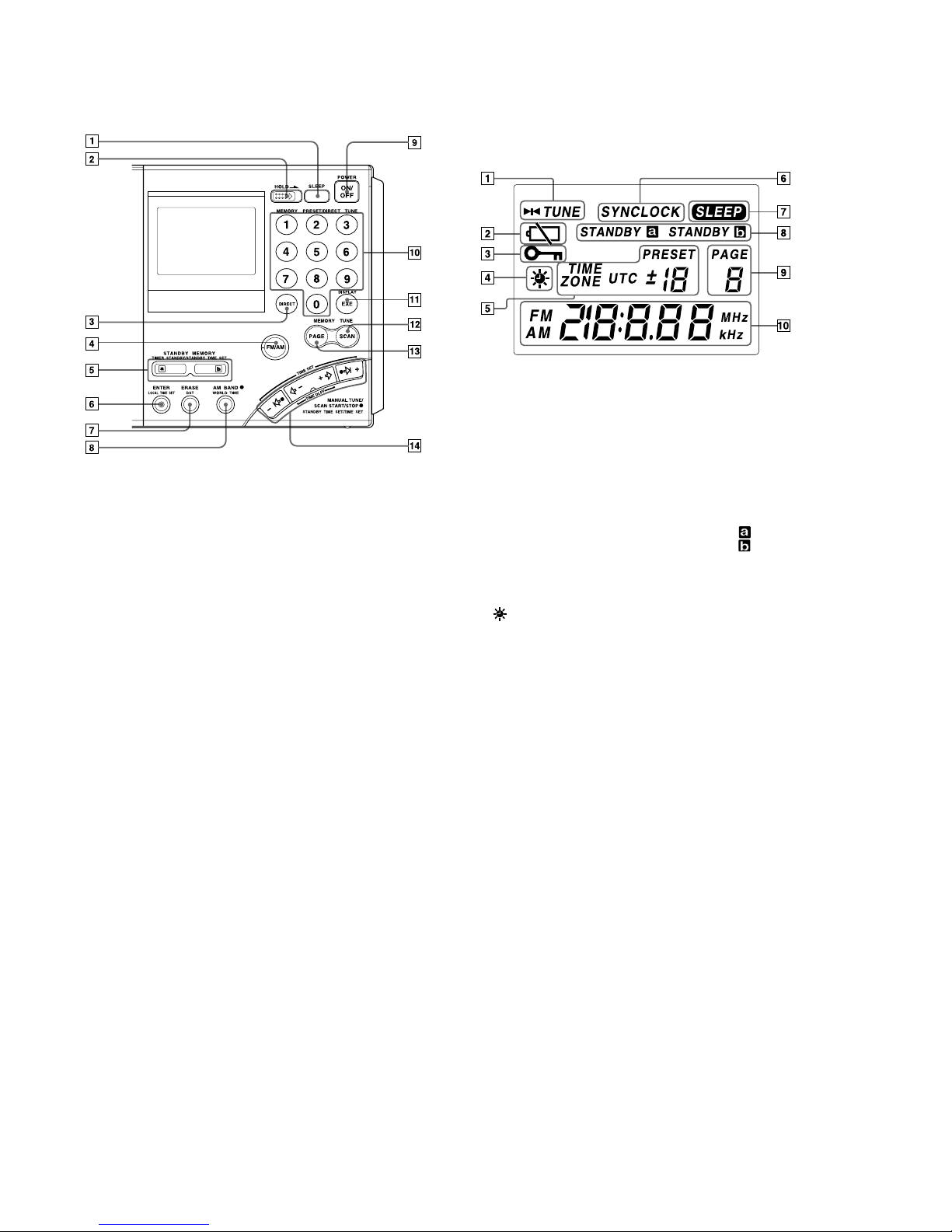
Controls
1 SLEEP button (31)
2 HOLD switch (32)
3 DIRECT button (15, 16)
4 FM/AM button (16, 18, 20)
5 STANDBY MEMORY,
TIMER STANDBY/
STANDBY TIME SET
buttons (28, 30)
6 ENTER, LOCAL TIME
SET button (11, 22, 28)
7 ERASE, DST (Daylight
Saving Time) button (11,
13, 30)
8 AM BAND, WORLD
TIME button (13, 18, 20)
9 POWER ON/OFF button
0 Number buttons (15, 16,
22, 23, 24)
qa DISPLAY, EXE button
(13, 15, 16)
Press to switch to clock
display while operating
the radio. Press again to
return to the previous
display. If you do not
press the button, the
display will return to the
previous condition in
about 10 seconds.
qs SCAN button (24)
qd PAGE button (22, 24)
qf MANUAL TUNE/SCAN
START/STOP, STANDBY
TIME SET/TIME SET
buttons (11, 13, 18, 20, 28)
Display
1 TUNE indicator (16, 18)
Appears when a station
is tuned in.
2 Battery indicator (9)
3 HOLD indicator (32)
Appears when HOLD is
in effect. All buttons will
be inoperative.
4
(Daylight Saving
Time) indicator (12)
Appears when the time
display is adjusted to the
Daylight Saving Time.
5 Preset number/time
difference display (11, 22,
23)
6 SYNCLOCK
(synchronous detection
lock) indicator (27)
Appears when
synchronous detection is
in effect.
7 SLEEP indicator (31)
Appears when the sleep
timer is in effect.
8 STANDBY
,
STANDBY
indicators
(28, 29, 30)
Light up when the
standby timer is set.
9 PAGE number display
Appears constantly when
the radio is on.
0 Time/frequency display
5
ICF-SW7600GR
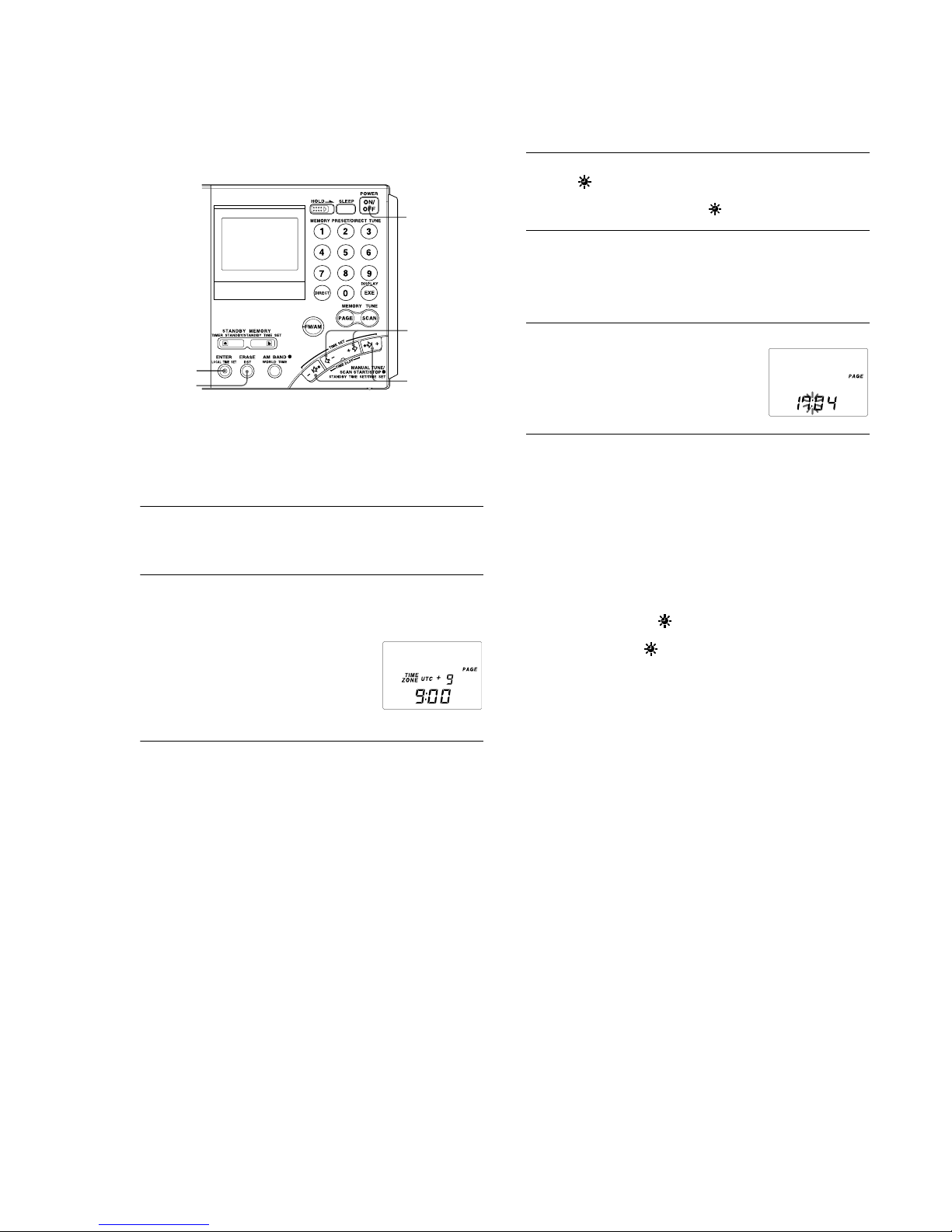
Setting the Current Time
“0:00” flashes in the display when installing the batteries for the first time
or when the unit has been reset. Set the clock to the current time.
This unit can display local time, which is the time for your time zone, as
well as world time, which is the time for any other area in the world.
For the calculation of the time in other areas of the world, the time
difference* between the local time and the UTC (Universal Time
Coordinated) is used (see page 14, “Time difference with UTC for each
area”). To find out the correct time, set the correct time and time
difference of the area you are in.
* This unit uses time zones to pinpoint specific areas.
1
If the radio is turned on, press POWER ON/OFF to
turn it off.
Note
You cannot set the clock when the radio is turned on.
2
Hold down LOCAL TIME SET and press K – or + k
to choose the time difference between your local time
and the UTC.
TIME ZONE indicator will appear. Each time you press K – or
+
k, the time difference (UTC + or –) and
the “hour” of the clock will increase or
decrease accordingly.
Two short beeps will be heard when
adjusting the time difference to ±0.
When you release LOCAL TIME SET, the
TIME ZONE indicator will disappear and the time difference with
UTC will be determined.
1
2
4
3
2, 4, 5
3
To set the daylight saving time, press DST to display
the
indicator.
If daylight saving time is not used in your area, daylight saving
time is not currently in effect, or
is already displayed, proceed
to Step 4.
4
Hold down LOCAL TIME SET and press –?K or k?
+
to set the local time.
Each time you press –?K or k?+, the current time will decrease or
increase by a minute. To change the digits rapidly, hold down –?K
or k?+.
Two short beeps will be heard when adjusting the time to “0:00”.
5
Release LOCAL TIME SET.
“ : ” starts flashing and the clock starts
running.
To switch to clock display while the radio is turned on
Press EXE. The display returns to the previous condition
automatically after about 10 seconds or when EXE is pressed
again. The time display period is extended when the WORLD
TIME button is pressed during clock display, or when K – or
+
k is pressed during world time display. During clock display,
radio operations such as changing frequencies are not possible.
The clock will not be displayed during auto scan (page 20) or
memory scan (page 24).
For areas adopting the daylight saving time (summer time)
Press DST to display the
indicator if you are now in the
summer time period. When the summer time period has ended,
press DST to clear the
indicator. The time display will be
adjusted automatically.
Tips
• The clock is displayed in the 24 hour system.
• Press LOCAL TIME SET to stop the flashing of “0:00”.
• To adjust the time to the second, release LOCAL TIME SET at the time
of the tone.
6
ICF-SW7600GR
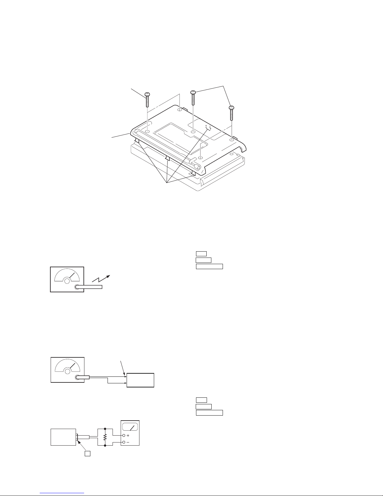
SECTION 2
DISASSEMBLY
Note : Follow the disassembly procedure in the numerical order given.
2-1. CABINET (REAR)
SECTION 3
ELECTRICAL ADJUSTMENTS
Put the lead-wire
antenna close to
the set.
AM RF signal
generator
30% amplitude
modulation by
400Hz signal
output level: as low as possible
i
headphones jack (J202)
level mete
r
set
16 Ω
• AM Section
• FM Section
(1) AM / FM VCO Check and Adjustment
Setting:
ATT switch : OFF
TONE switch : MUSIC
AM MODE switch : NORM
Procedure:
1. Connect digital voltmeter to the TP VT.
2. Tune the set to AM 150kHz.
3. Confirm that the reading on the digital voltmeter becomes in
more than 2.2V.
4. Tune the set to AM 29999kHz.
5. Confirm that the reading on the digital voltmeter becomes in
less than 13V.
6. Tune the set to FM 108.00MHz.
7. Confirm that the reading on the digital voltmeter becomes in
less than 13V.
8. IF the value is more than 13V, adjust T202 so that the reading
on the digital voltmeter becomes in 12.5V.
Adjustment Location: MAIN board (See page 8)
(2) 1st IF Adjustment
Setting :
ATT switch : OFF
TONE switch : MUSIC
AM MODE switch : NORM
Procedure:
1. Set the frequencies of the AM RF signal generator and the
frequency display of the set to AM 150kHz.
2. Adjust T104 and T105 so that the reading on level meter
becomes in maximum.
Adjustment Location: MAIN board (See page 8)
FM RF signal
generator
FM RF IN
22.5kHz frequency
deviation by 400Hz signal
output level: as low as possible
set
1 Three screws (+BTP 3 × 25
)
2 Two screws (+BTP 3 × 25)
4 Cabinet (rear)
3 Four claws
7
ICF-SW7600GR
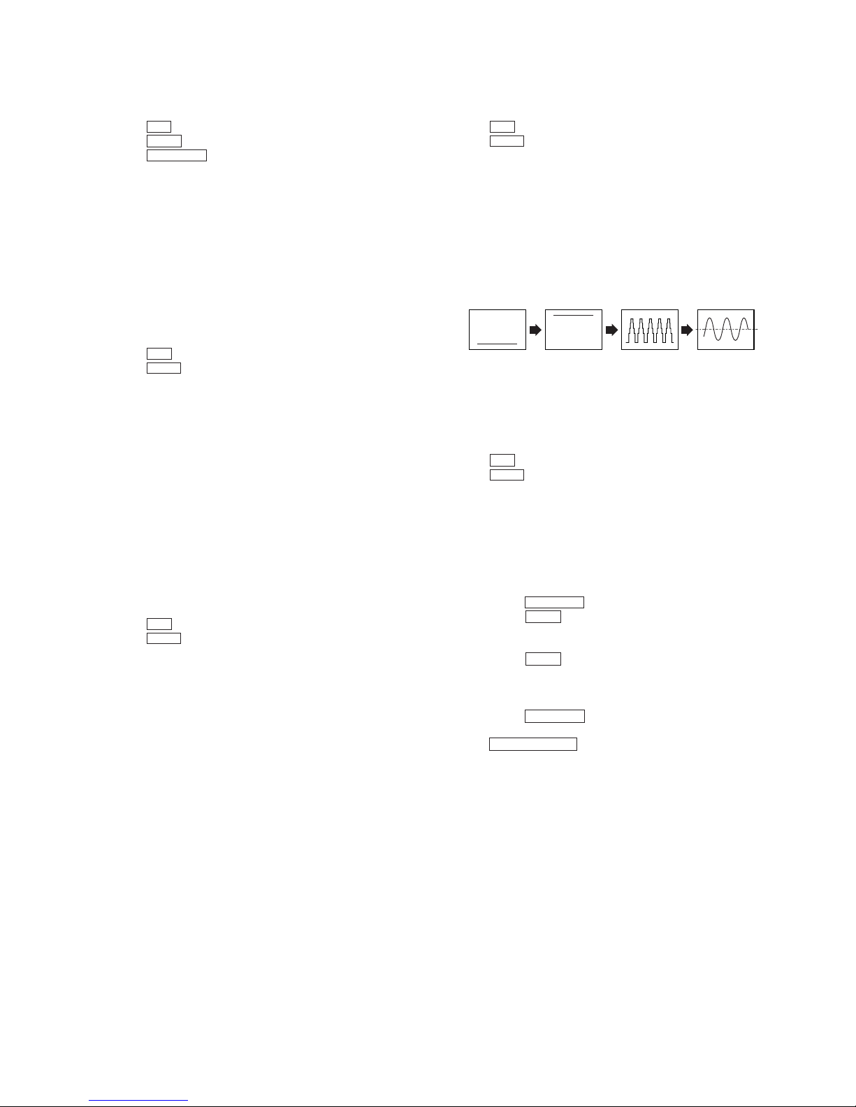
NG
Cente
r
NG
NG
OK
(3) 2nd Local Adjustment
Setting:
ATT switch : OFF
TONE switch : MUSIC
AM MODE switch : NORM
Procedure:
1. Connect frequency counter to the TP OSC2 through the high
input impedance amplifier.
2. Tune the set to AM 150kHz.
3. Adjust CT202 so that the reading on the frequency counter
becomes in 55.39000MHz±30Hz.(55.38997 to 55.39003MHz)
Adjustment Location: MAIN board (See page 8)
(4) FM Tracking Adjustment
Setting:
ATT switch : OFF
TONE switch : MUSIC
Procedure:
1. Set the frequency of the FM RF signal generator and the
frequency display of the set to FM 108.00MHz.
2. Adjust CT101 and CT102 so that the reading on level meter
becomes in maximum.
3. Set the frequency of the FM RF and the frequency display of
the set to FM 76.00MHz.
4. Adjust T101 and T102 so that the reading on level meter
becomes in maximum.
5. Repeat the above steps 1 to 4 several times.
Adjustment Location: MAIN board (See page 8)
(5) 76kHz (MPX) Adjustment
Setting:
ATT switch : OFF
TONE switch : MUSIC
Procedure:
1. Insert Headphones plug into headphones jack (J202) (for VCO
operation).
2. Connect a capacitor (10µF) between IC202 pin1 and GND.
3. Connect frequency counter to the TP 76K (VCO) through the
high input impedance amplifier.
4. Tune the set to FM 108.00MHz.
5. Adjust RV203 so that the reading on the frequency counter
becomes in 76kHz±300Hz.
6. Remove the headphones plug.
Adjustment Location: MAIN board (See page 8)
(6) Just Tune Adjustment
Setting :
ATT switch : OFF
TONE switch : MUSIC
(FM RF signal generator)
Frequency : 93.025MHz
Moduration : 22.5kHz
Output level : 54dB
Procedure:
1. Connect an oscilloscope to the TP SD.
2. Tune the set to FM 93.00MHz.
3. Adjust R V202 so that the wav eform on the oscilloscope satisfy
as shown the figure.
Adjustment Location: MAIN board (See page 8)
(7) SSB 0 Beat Adjustment
Setting :
ATT switch : OFF
TONE switch : MUSIC
(AM RF signal generator)
Frequency : AM 150kHz
Moduration : None
Output level : 44dB
Procedure:
1. Connect an oscilloscope to the TP DET.
2. Tune the set to AM 150kHz.
3. Set the AM MODE switch to SYNC.
4. Set the SYNC switch to USB.
5. Adjust CT201 so that the waveform on the oscilloscope is
minimized.
6. Set the SYNC switch to LSB.
7. Adjust CT201 so that the waveform on the oscilloscope is
minimized.
8. Repeat the above steps 4 to 7 several times.
9. Set the AM MODE switch to SSB.
10. Confirm that the beat sound is changed by turning the
SSB FINE TUNE control.
Adjustment Location: MAIN board (See page 8)
8
ICF-SW7600GR
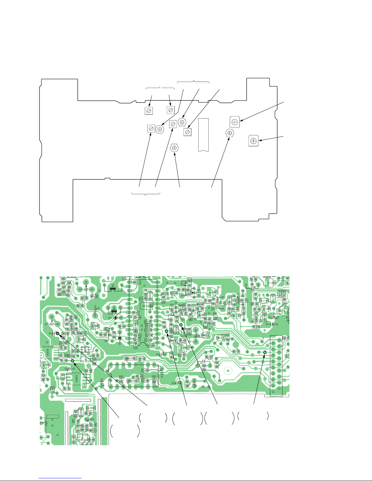
Adjustment Location :
[MAIN BOARD] — Component Side —
[MAIN BOARD] — Conductor Side —
T104 T105
1st IF
Adjustment
T202
FM
VCO
Adjustment
IC201
RV202
JUST TUN
E
Adjustment
CT101 CT102
FM TRACKING
Adjustment
(108MHz)
T101 T102
FM TRACKING
Adjustment
(76MHz)
CT202
2nd LOCAL
Adjustment
CT201
SSB
0 BEAT
Adjustment
RV203
76kHz
(MPX)
Adjustment
RV204
VOLUME
RV203
C231
C272
C262
C
1
C135
C221
C259
C209
CF205
CT201
CF204
CF203
C267
C253
C261
C260
RV202
X201
CT202
C152
CT102
T102
T202
CT101
T107
CF201
15
1
18
916
16
30
1
17
18
2
CN201
IC203
IC201
T101
T103
2C 2E
2C
2C
1E
1B
1B
2E
E
2B
2B
1C
1C
2C
1B
E
2B
1C
K
KA
C
B
E
C
B
E
C
B
E
1
1
45
8
5
S
D
G
S
S
D
D
G
G
B
B
B
E
E
E
C
C
C
B
E
C
K
K
A
A
K
A
AAK
K
C
E
B
A
E
C
VT
AM/FM VCO
Adjustment
OSC2
2nd
LOCAL
Adjustment
SD
JUST
TUNE
Adjustment
76K (VCO)
MPX
Adjustment
DET
SSB
0 BEAT
Adjustment
 Loading...