

Sony ICFC-723 Service manual
ICF-C723/C723L
SERVICE MANUAL
Ver 1.1
SPECIFICATIONS
Radio section
Frequency range :
US, Canadian model
Band ICF-C723 Channel step
FM 87.5– 108 MHz 0.1MHz
AM 530 – 1,710 kHz 10kHz
EXCEPT US, Canadian model
Band ICF-C723 ICF-C723L Channel step
FM 87.5– 108 MHz 87.5– 108 MHz 0.05MHz*
AM (MW) 531 – 1,602 kHz 530 – 1,602 kHz 9kHz
LW –––––––– 530 – 1,602 kHz 9kHz
* The frequency display is raised or lowerd by steps of
0.1MHz.
(Example : Frequency 88.05 MHz is displayed as “88.0
MHz”.)
US Model
Canadian Model
E Model
Australian Model
ICF-C723
UK Model
ICF-C723L
AEP Model
ICF-C723/C723L
General
Time display
US, Canadian, UK model 12-hour
EXCEPT US, Canadian, UK model 24-hour
Speaker Approx. 5.7 cm (2 1/4 in) dia.
Power output
100 mW (at 10% harmonic distortion)
Power requirements
US, Canadian model :120V AC, 60Hz
EXCEPT US, Canadian model : 220 – 230V AC, 50Hz
Dimensions
Approx. 181 x 103 x 133 mm (w/h/d)
(7 1/4 x 4 1/8 x 4 1/4 in) incl. projecting parts and controls
Mass Approx. 550 g (1 lb 3.4 oz)
Approx. 600 g (1 lb 5.2 oz) : ICF-C723L (UK model)
Design and specifications are subject to change without notice.
DIGITAL VOICE MEMO Recording section
Recording media
Built-in flash memory
Recording time
20 seconds
Frequecy response
400Hz – 2,700Hz
MICROFILM
ICF-C723
FM/AM PLL SYNTHESIZED CLOCK RADIO
ICF-C723L
FM/MW/LW PLL SYNTHESIZED CLOCK RADIO
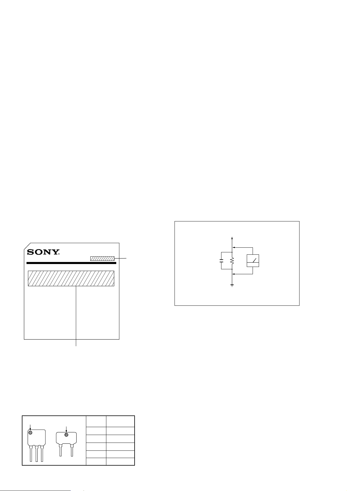
TABLE OF CONTENTS
SAFETY CHECK-OUT
Specifications ........................................................................... 1
1. GENERAL
Location and Function of Controls .................................... 3
2. DISASSEMBLY
2-1. Cabinet (Upper) Removal........................................... 4
2-2. Microcomputer Board Removal ................................. 4
2-3. Main Board, Key Board, Transformer (Primary)
Board, Transformer (Secondary) Board Removal ...... 5
Installation Power Cord ..................................................... 5
3. ELECTRICAL ADJUSTMENT................................ 6
4. DIAGRAMS
4-1. Explanation of IC Terminal ........................................ 8
4-2. Printed Wiring Board (Microcomputer Section) ........ 9
4-3. Schematic Diagram ((Microcomputer Section).........11
4-4. Printed Wiring Board (Main Section)....................... 13
4-5. Schematic Diagram (Main Section) ......................... 15
5. EXPLODED VIEW..................................................... 18
6. ELECTRICAL PARTS LIST................................... 19
After correcting the original service problem, perform the
following safety check before releasing the set to the customer :
Check the antenna terminals, metal trim, “metallized” knobs,
screws, and all other exposed metal parts for AC leakage. Check
leakage as described below.
LEAKAGE TEST
The AC leakage from any exposed metal part to earth ground
and from all exposed metal parts to any exposed metal part
having a return to chassis, must not exceed 0.5mA (500
microampers).
Leakage current can be measured by any one of three methods.
1. A commercial leakage tester, such as the Simpson 229 or
RCA WT-540A. Follow the manufacturers’ instructions to
use these instruments.
2. A battery-operated AC milliammeter. The Data Precision 245
digital multimeter is suitable for this job.
3. Measuring the voltage drop across a resistor by means of a
VOM or battery-operated AC voltmeter. The “limit” indication is 0.75V, so analog meters must have an accurate lowvoltage scale. The Simpson 250 and Sanwa SH-63Trd are
examples of a passive VOM that is suitable. Nearly all
battery operated digital multimeters that have a 2V AC range
are suitable. (See Fig. A)
MODEL IDENTIFICATION
– Model Number Portion –
Carved on lower cabinet
MODEL NO.
ICF-C723
ICF-C723L
US, Canadian model : AC : 120V⁄60Hz 5W
AEP, UK, Italian,
E, Australian model : AC : 220 – 230V⁄50Hz 5W
• HOW TO CHANGE THE CERAMIC FILTER
This model is used two ceramic filters of CF1 and CF3.
You must use same type of color marked ceramic filters in
order to meet same specifications.
Therefore, the ceramic filter must change two pieces together
since it's supply two pieces in package as a spare parts.
mark
mark
Mark
Center
frequency
red 10.70MHz
CF3
CF1
blue 10.67MHz
orange 10.73MHz
black 10.64MHz
white 10.76MHz
To Exposed Metal
Parts on Set
1.5k
0.15
µ
F
Fig. A. Using an AC voltmeter to check AC leakage.
SAFETY-RELATED COMPONENT WARNING!!
COMPONENTS IDENTIFIED BY MARK ! OR DOTTED LINE WITH
MARK ! ON THE SCHEMATIC DIAGRAMS AND IN THE PARTS
LIST ARE CRITICAL TO SAFE OPERATION.
REPLACE THESE COMPONENTS WITH SONY PARTS WHOSE
PART NUMBERS APPEAR AS SHOWN IN THIS MANUAL OR IN
SUPPLEMENTS PUBLISHED BY SONY.
ATTENTION AU COMPOSANT AYANT RAPPORT
LES COMPOSANTS IDENTIFIÉS P AR UNE MARQUE ! SUR LES
DIAGRAMMES SCHÉMA TIQUES ET LA LISTE DES PIÈCES SONT
CRITIQUES POUR LA SÉCURITÉ DE FONCTIONNEMENT. NE
REMPLACER CES COMPOSANTS QUE PAR DES PIÈCES SONY
DONT LES NUMÉROS SONT DONNÉS DANS CE MANUEL OU
DANS LES SUPPLÉMENTS PUBLIÉS PAR SONY.
À LA SÉCURITÉ!
Ω
Earth Ground
AC
voltmeter
(0.75V)
– 2 –
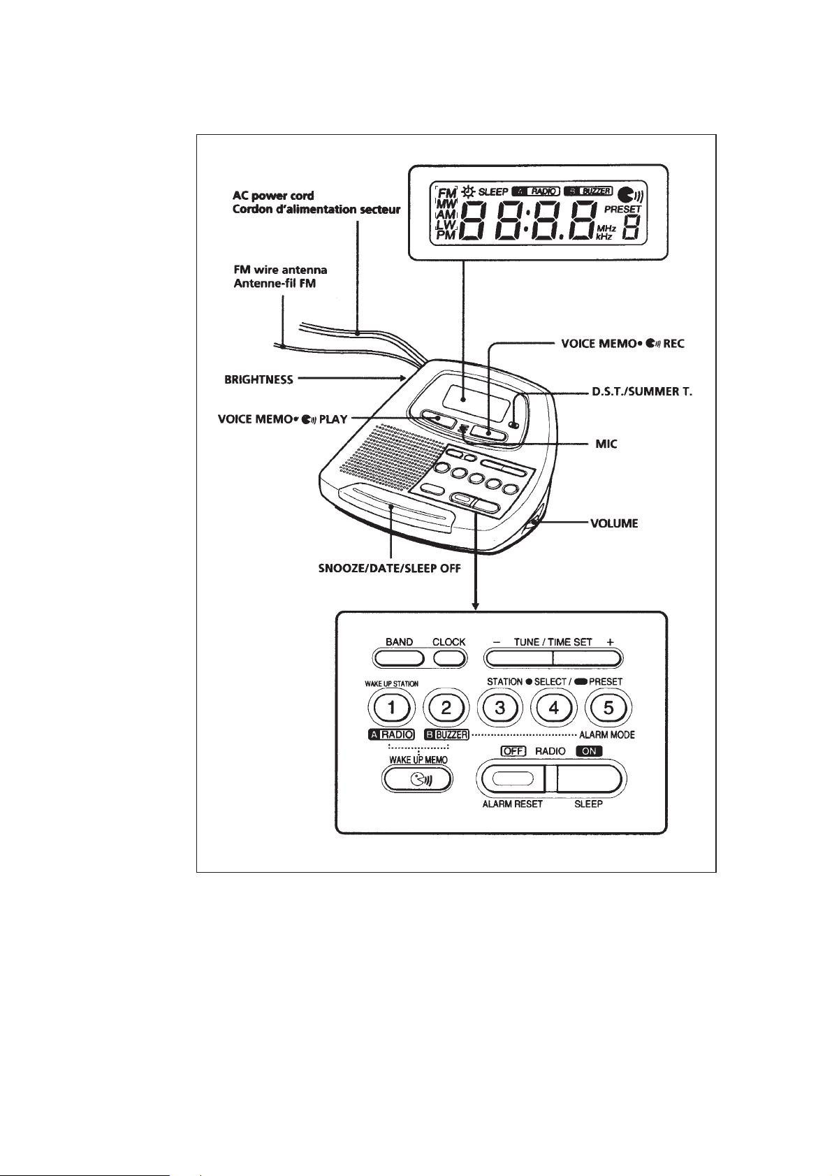
LOCATION AND FUNCTION OF CONTROLS
SECTION 1
GENERAL
*
* ICF-C723 : FM, AM
ICF-C723L : FM, MW, LW
– 3 –
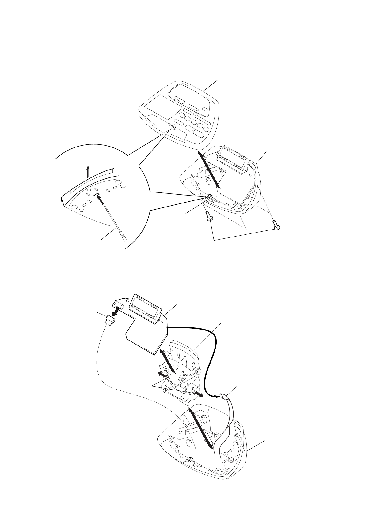
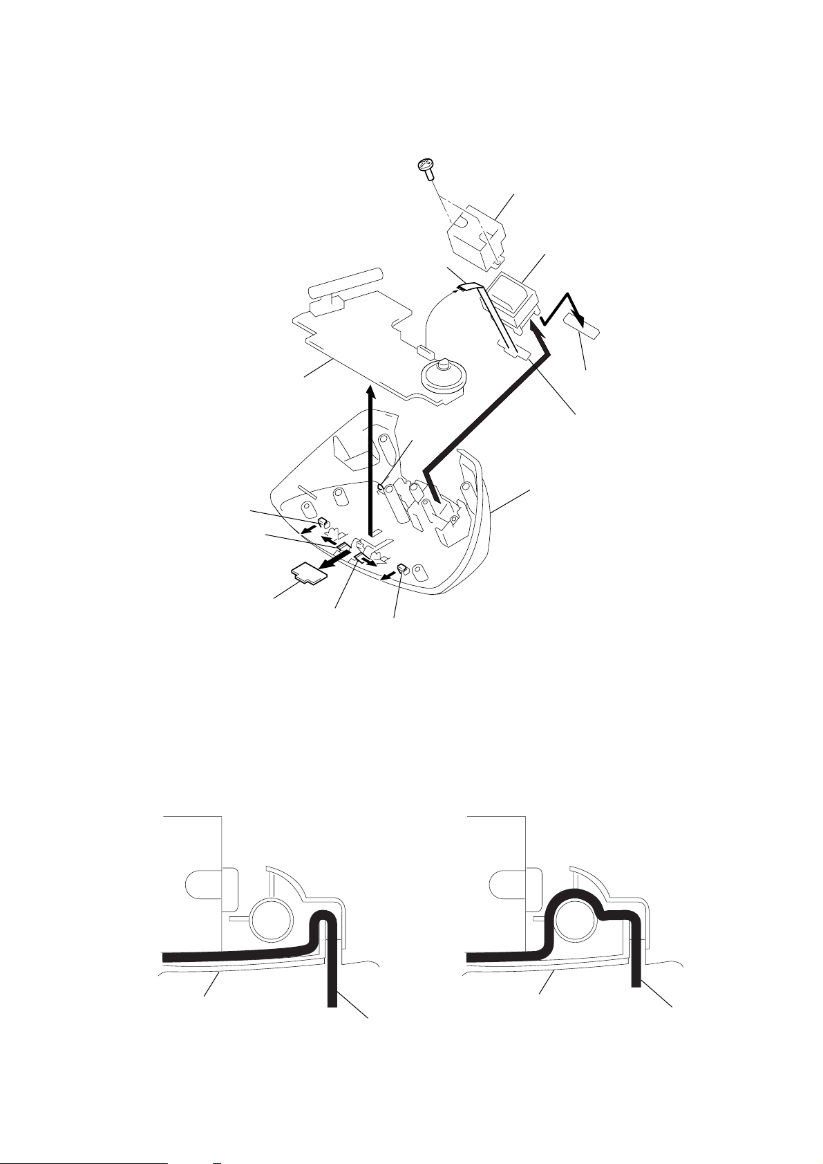
SECTION 2
DISASSEMBLY
Note : Follow the disassembly procedure in the numerical order given.
2-1. CABINET (UPPER) REMOVAL
3
Cabinet (Upper)
Cabinet (lower)
4
2
Precision driver
2-2. MICROCOMPUTER BOARD REMOVAL
1
CN101
4
Claw
Microcomputer board
1
Screws +P (3x14)
Holder (transformer)
3
Claws
– 4 –
5
2
CN102
Cabinet (lower)
2-3. MAIN BOARD, KEY BOARD, TRANSFORMER (PRIMARY) BOARD,
d
TRANSFORMER (SECONDARY) BOARD, REMOVAL
1
Screws +P (3x14)
Shield case (transformer)
3
CN1
Power transformer (T201)
Main board
4
Claw
6
Claw
Key board
INSTALLATION POWER CORD
6
7
Claw
5
4
4
Claw
Claw
2
8
Transformer (primary) board
9
Transformer (secondary) boar
Cabinet (lower)
US model
Cabinet (lower)
power cord
– 5 –
EXCEPT US model
Cabinet (lower)
power cord
r
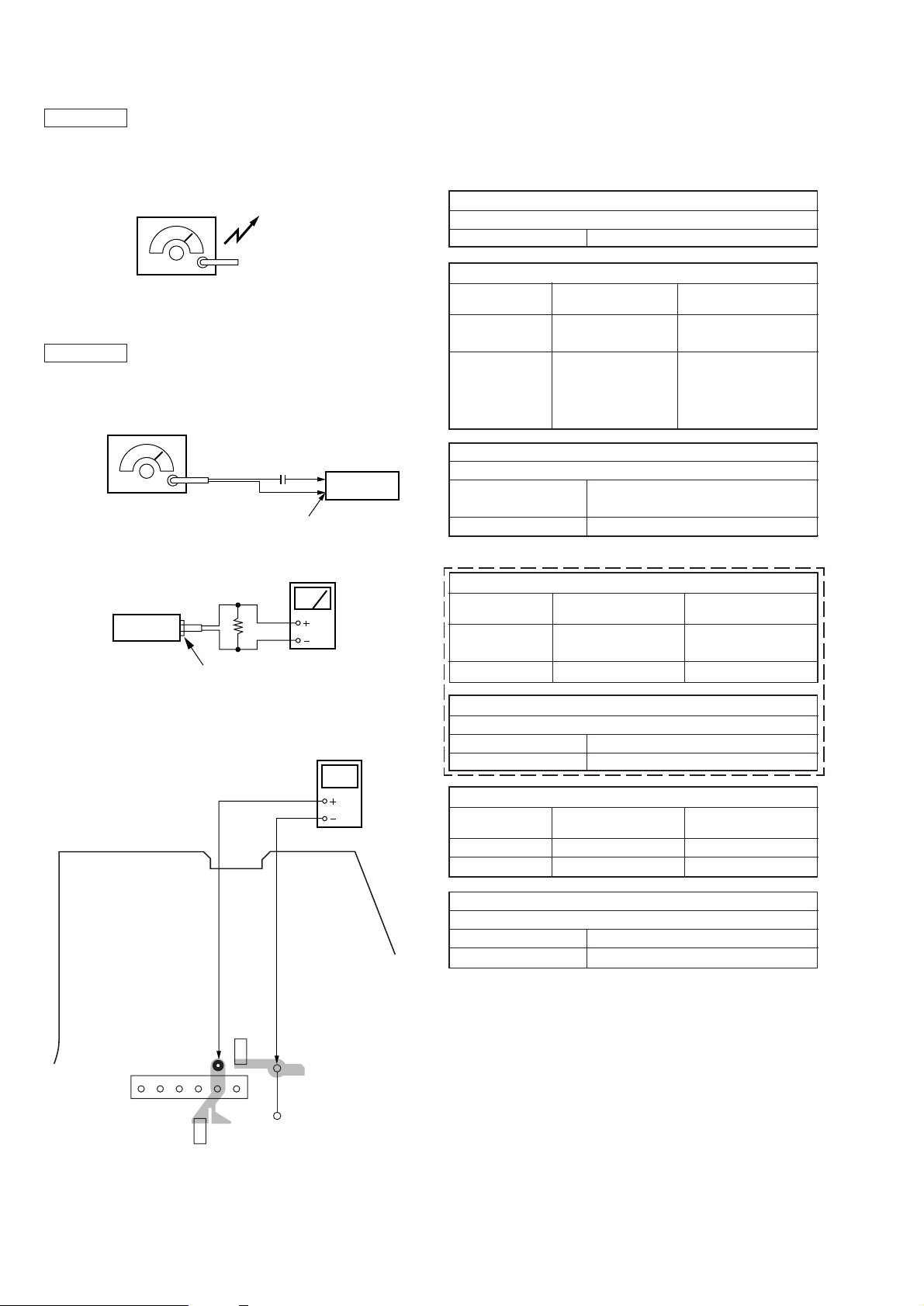
SECTION 3
ELECTRICAL ADJUSTMENTS
AM Section
Band button : AM (ICF-C723)
: MW or LW (ICF-C723L)
Volume : MAX
AM RF signal
generator
30% amplitude modulation by 400Hz
signal.
Output level : as low as possible
FM Section
Band button : FM
Volume : MAX
FM RF signal
generator
22.5kHz frequency
deviation by 400Hz signal.
Output level :
as low as possible
set
Put the lead-wire
antenna close to
the set.
0.01 F
FM ANT IN
level mete
8
Ω
speaker terminal
• Repeat the procedures in each adjustment several times, and the
frequency coverage and tracking adjustments should be finally
done by the trimmer capacitors.
( ): AEP, UK, Italian, Australian, E model only
AM IF ALIGNMENT
Adjust for a maximum reading on level meter.
T1 455kHz
AM <MW> FREQUENCY COVERAGE ADJUSTMENT
Adjust parts Frequecy display
L6 530kHz (531kHz)
confirmation 1,710kHz (1,602kHz)
µ
set
AM <MW> TRACKING ADJUSTMENT
Adjust for a maximum reading on level meter.
L3 :ICF-C723
L3–1 :ICF-C723L
CT1 1,490kHz (1,404kHz)
580kHz (621kHz)
Reading on digital
voltmeter
2.5 ± 0.1V (ICF-C723)
2.65 ± 0.1V (ICF-C723L)
Less than 11.0V
Standard 9.5V
(Less than 10.0V)
(Standard 9.0V)
ICF-C723L
LW FREQUENCY COVERAGE ADJUSTMENT
Adjust parts Frequecy display
confirmation 153kHz
CT4 279kHz 9.0 ± 0.1V
Reading on digital
voltmeter
More than 2.2V
(Standard 3V)
[MAIN BOARD] (Conductor side)
5
W705
4
C15
3
2
6
C55
1
JW13
digital
voltmeter
LW TRACKING ADJUSTMENT
Adjust for a maximum reading on level meter.
L3 – 2 162kHz
CT2 243kHz
FM FREQUENCY COVERAGE ADJUSTMENT
Adjust parts Frequecy display
L5 87.5MHz 3.0 ± 0.1V
confirmation 108.0MHz 10 ± 1V
FM TRACKING ADJUSTMENT
Adjust for a maximum reading on level meter.
L4 87.5MHz
CT3 108MHz
Reading on digital
Adjustment Location : Main board (See page 8)
voltmeter
– 6 –
 Loading...