

Sony ICFC-470, ICFC-470-L Service manual
ICF-C470/C470L
SERVICE MANUAL
Ver 1.1 1999. 06
With SUPPLEMENT 1
(9-926-981-81)
Photo: ICF-C470
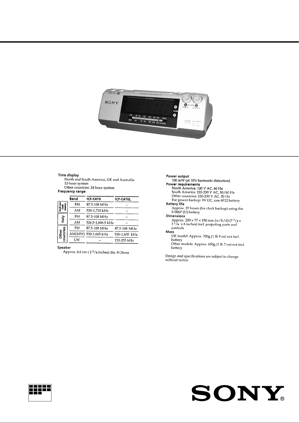
SPECIFICATIONS
US Model
Canadian Model
E Model
Australian Model
ICF-C470
AEP Model
ICF-C470/C470L
UK Model
ICF-C470L
MICROFILM
ICF-C470
FM/AM CLOCK RADIO
ICF-C470L
FM/MW/LW 3 BAND CLOCK RADIO
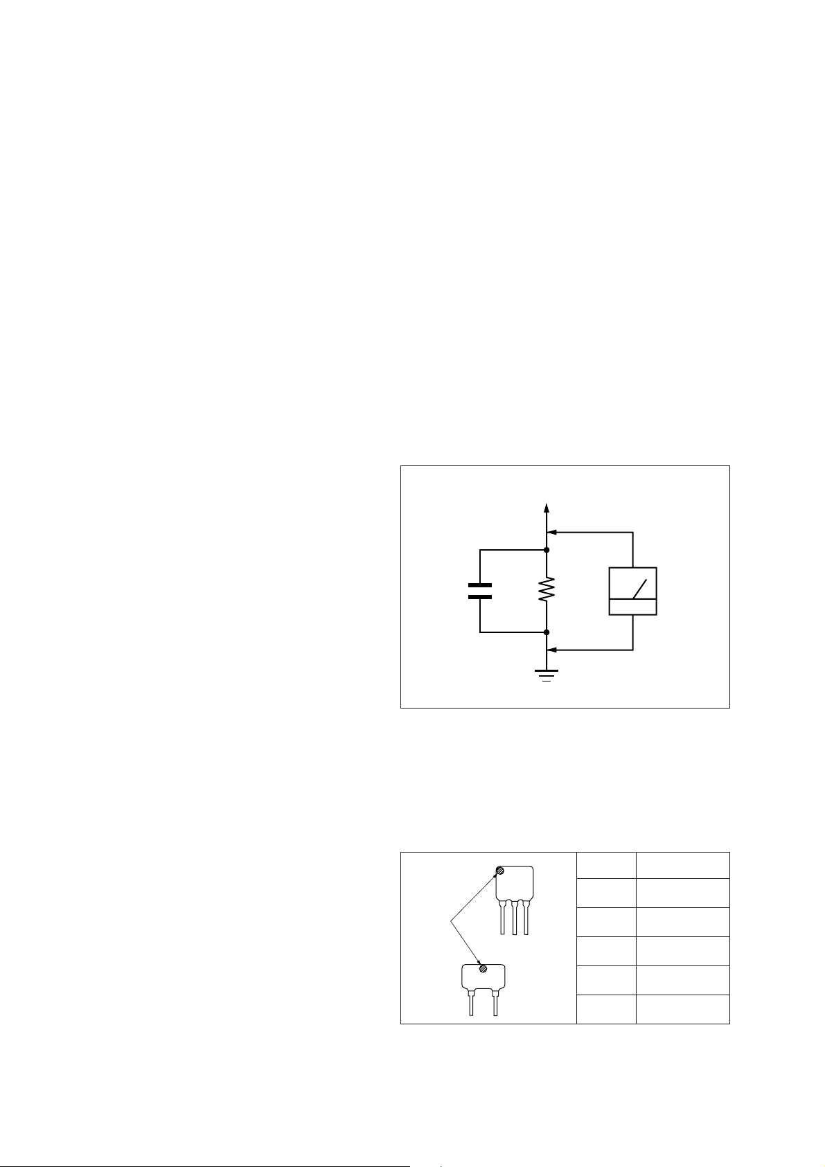
TABLE OF CONTENTS
2
1. GENERAL ................................................................... 3
2. DISASSEMBLY ......................................................... 4
3. DIAL POINTER SETTING..................................... 5
4. POWER CORD SETTING ..................................... 6
5. ELECTRICAL ADJUSTMENTS.......................... 7
6. DIAGRAMS
6-1. Block Diagram ................................................................ 9
6-2. Printed Wiring Boards (ICF-C470) ................................ 11
6-3. Schematic Diagram (ICF-C470)..................................... 13
6-4. Printed Wiring Boards (ICF-C470L).............................. 15
6-5. Schematic Diagram (ICF-C470L) .................................. 17
7. EXPLODED VIEWS ................................................ 20
8. ELECTRICAL PARTS LIST ............................... 22
SAFETY CHECK-OUT
After correcting the original service problem, perform the following safety check before releasing the set to the customer:
Check the antenna terminals, metal trim, “metallized” knobs,
screws, and all other exposed metal parts for AC leakage.
Check leakage as described below.
LEAKAGE TEST
The A C leaka ge from an y e xposed metal part to earth gr ound and
from all exposed metal parts to any exposed metal part having a
return to chassis, must not exceed 0.5 mA (500 microampers.).
Leakage current can be measured by any one of three methods.
1. A commercial leakage tester , such as the Simpson 229 or RCA
WT -540A. Follo w the manufacturers’ instructions to use these
instruments.
2. A battery-operated AC milliammeter. The Data Precision 245
digital multimeter is suitable for this job.
3. Measuring the voltage drop across a resistor by means of a
VOM or battery-operated AC voltmeter. The “limit” indication is 0.75 V, so analog meters must have an accurate lowvoltage scale. The Simpson 250 and Sanwa SH-63T rd are e xamples of a passive VOM that is suitable. Nearly all battery
operated digital multimeters that have a 2 V A C range are suitable. (See Fig. A)
To Exposed Metal
Parts on Set
SAFETY-RELATED COMPONENT WARNING!!
COMPONENTS IDENTIFIED BY MARK ! OR DOTTED
LINE WITH MARK ! ON THE SCHEMATIC DIAGRAMS
AND IN THE PARTS LIST ARE CRITICAL TO SAFE
OPERATION. REPLACE THESE COMPONENTS WITH
SONY PARTS WHOSE PART NUMBERS APPEAR AS
SHOWN IN THIS MANUAL OR IN SUPPLEMENTS PUBLISHED BY SONY.
ATTENTION AU COMPOSANT AYANT RAPPORT
À LA SÉCURITÉ!
LES COMPOSANTS IDENTIFIÉS P AR UNE MARQ UE !
SUR LES DIAGRAMMES SCHÉMATIQUES ET LA LISTE
DES PIÈCES SONT CRITIQUES POUR LA SÉCURITÉ
DE FONCTIONNEMENT. NE REMPLACER CES COMPOSANTS QUE PAR DES PIÈCES SONY DONT LES
NUMÉROS SONT DONNÉS DANS CE MANUEL OU
DANS LES SUPPLÉMENTS PUBLIÉS PAR SONY.
AC
1.5 k
0.15 µF
Fig. A. Using an AC voltmeter to check AC leakage.
Ω
Earth Ground
voltmeter
(0.75 V)
HOW TO CHANGED THE CERAMIC FILTERS
This model is used two ceramic filters of CF2 and CF3.
You must used same type of color marked ceramic filters in order
to meet same specifications.
Therefore, the ceramic filter must changed two pieces together
since it’s supply two pieces in one package as a spare parts.
Mark Center frequency
CF
mark
red 10.70 MHz
blue 10.67 MHz
orange 10.73 MHz
CF3
black 10.64 MHz
white 10.76 MHz
Notes on chip component replacement
• Never reuse a disconnected chip component.
• Notice that the minus side of a tantalum capacitor may be dam-
aged by heat.
– 2 –
SECTION 1
GENERAL
This section is extracted from
instruction manual.
– 3 –

SECTION 2
)
DISASSEMBLY
Note: Follow the disassembly procedure in the numerical order given.
CABINET (LOWER)
1
five screws
×
14)
(P3
3
cabinet (lower
MAIN BLOCK
5
buzzer board
2
two claws
1
power transformer
6
Break the soldering
of speaker lead.
4
two claws
2
three claws
for chassis
– 4 –
3
main block
2
three claws
for PWB
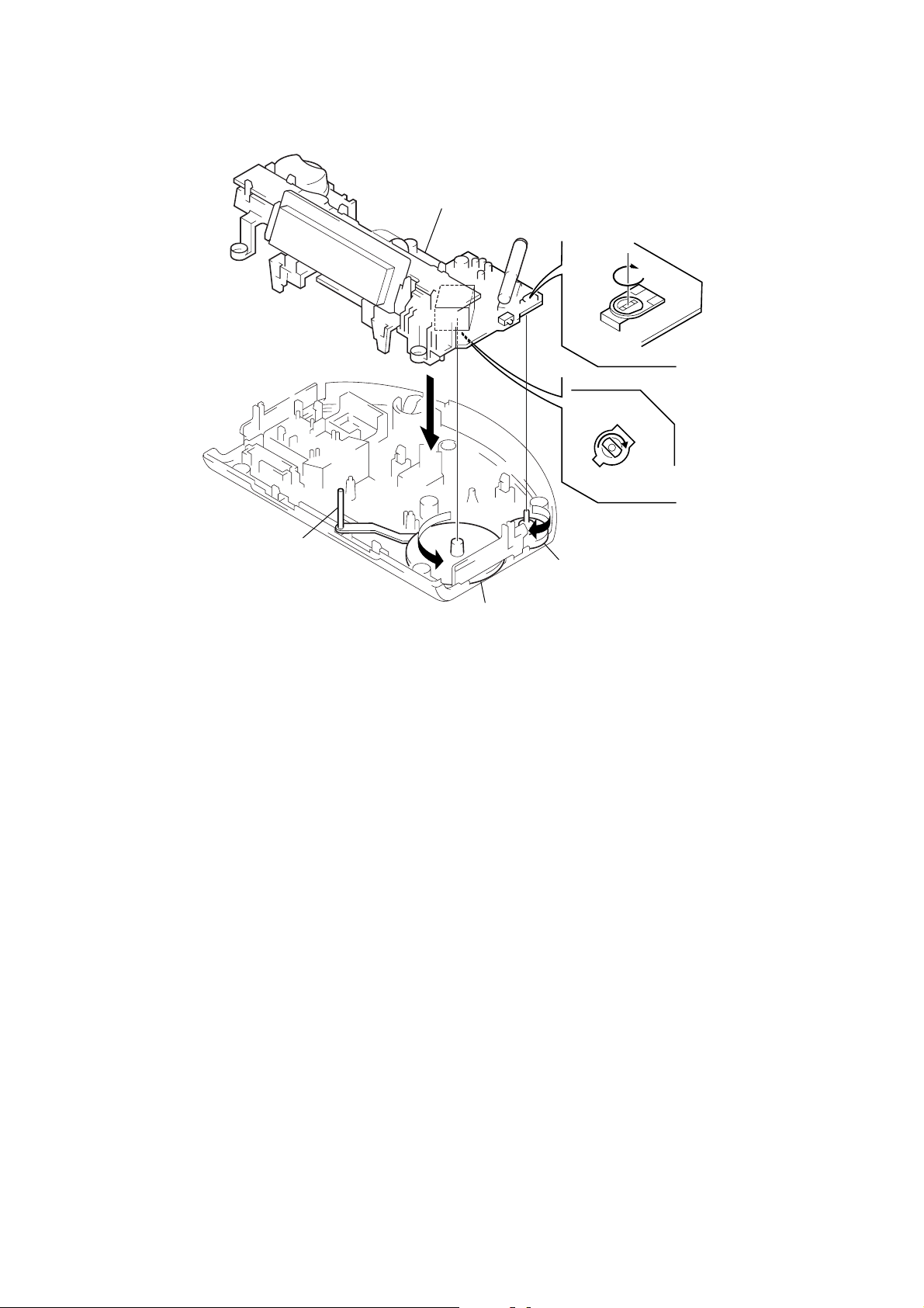
SECTION 3
DIAL POINTER SETTING
Note: Follow the assembly procedure in the numerical order given.
dial pointer
A
5
Install the MAIN board.
D
4
– BOTTOM VIEW –
C
3
Turn shaft of CV1 to the
arrow
C
direction fully.
B
2
Turn the knob (VOL) to the
arrow
B
direction fully.
Turn VR1 to the
arrow
D
direction fully.
1
Turn the knob (tuning) to the
A
arrow
direction fully.
– 5 –
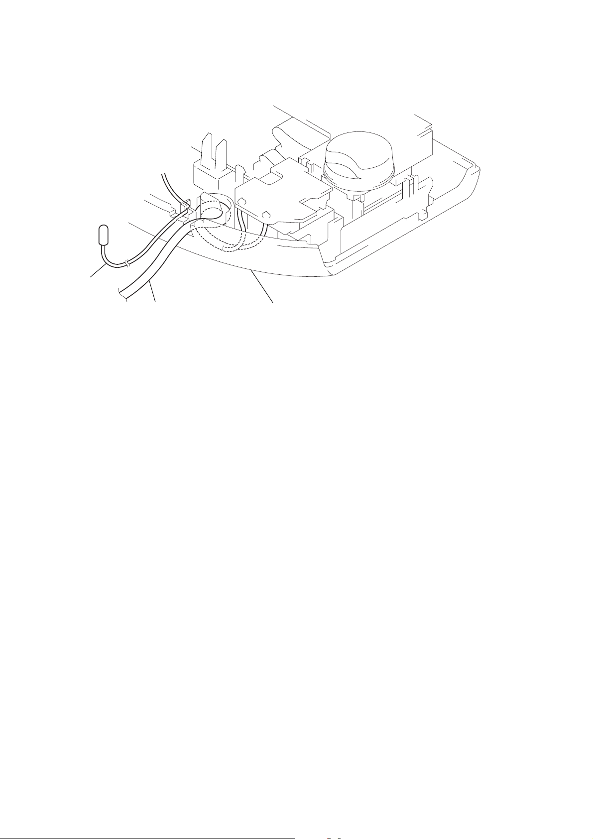
Set the power cord as illustrated below,
then install the lower cabinet.
FM antenna
SECTION 4
POWER CORD SETTING
power cord
lower cabinet
– 6 –
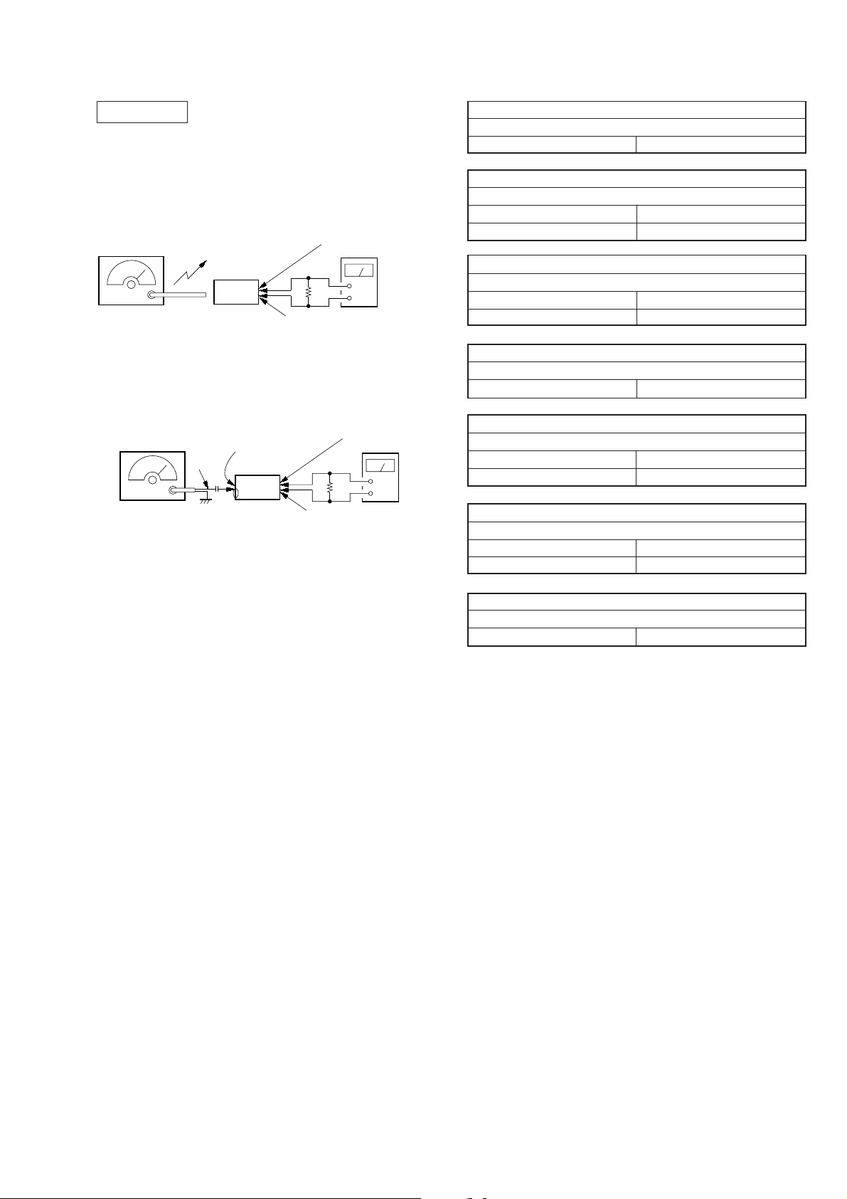
SECTION 5
ELECTRICAL ADJUSTMENTS
0 dB = 1 µV
[AM (MW/LW)*]
*AM : ICF-C470
MW/LW: ICF-C470L
Setting:
Band switch: AM (MW/LW)
AM RF signal
generator
30% amplitude
modulation by
400 Hz signal
Output level: as low as possible
Put the lead-wire
antenna close to
the set.
set
[FM]
Setting:
Band switch: FM
FM RF signal
generator
0.01 µF
22.5 kHz frequency
deviation by 400 Hz
signal
Output level: as low as possible
MAIN board
TP (FM ANT)
set
• Repeat the procedures in each adjustment several times, and the
frequency coverage and tracking adjustments should be finally
done by the trimmer capacitors.
• Remove FM antenna in FM adjustments.
Adjustment Location: Main Board (See page 8)
MAIN board
TP (SPK +)
level meter
8
Ω
+
–
MAIN board TP (SPK –)
MAIN board
TP (SPK +)
level meter
8
Ω
MAIN board TP (SPK –)
+
–
AM IF ADJUSTMENT
Adjust for a maximum reading on level meter
T1 455 kHz
AM (MW *2) FREQUENCY COVERAGE ADJUSTMENT
Adjust for a maximum reading on level meter
L4 520 kHz
CT1-3 1,750 kHz (1,650 kHz *1)
AM (MW *2) TRACKING ADJUSTMENT
Adjust for a maximum reading on level meter
L1 (L1-1 *2) 600 kHz
CT1-4 1,400 kHz
LW FREQUENCY COVERAGE ADJUSTMENT *2
Adjust for a maximum reading on level meter
CT6 145 kHz
LW TRA CKING ADJUSTMENT *2
Adjust for a maximum reading on level meter
L1-2 160 kHz
CT5 240 kHz
FM FREQUENCY COVERAGE ADJUSTMENT
Adjust for a maximum reading on level meter
L2 86.5 MHz
CT1-1 109.5 MHz
FM TRACKING ADJUSTMENT
Adjust for a maximum reading on level meter
CT1-2 109.5 MHz
*1) Except US, Canadian models
*2) ICF-C470L
– 7 –
 Loading...