

Sony ICF-C290,ICF-C290L Service Manual
ICF-C290
FM/AM CLOCK RADIO
ICF-C290L
FM/LW CLOCK RADIO
MICROFILM
AEP Model
ICF-C290/C290L
UK Model
E Model
Austr alian Model
ICF-C290
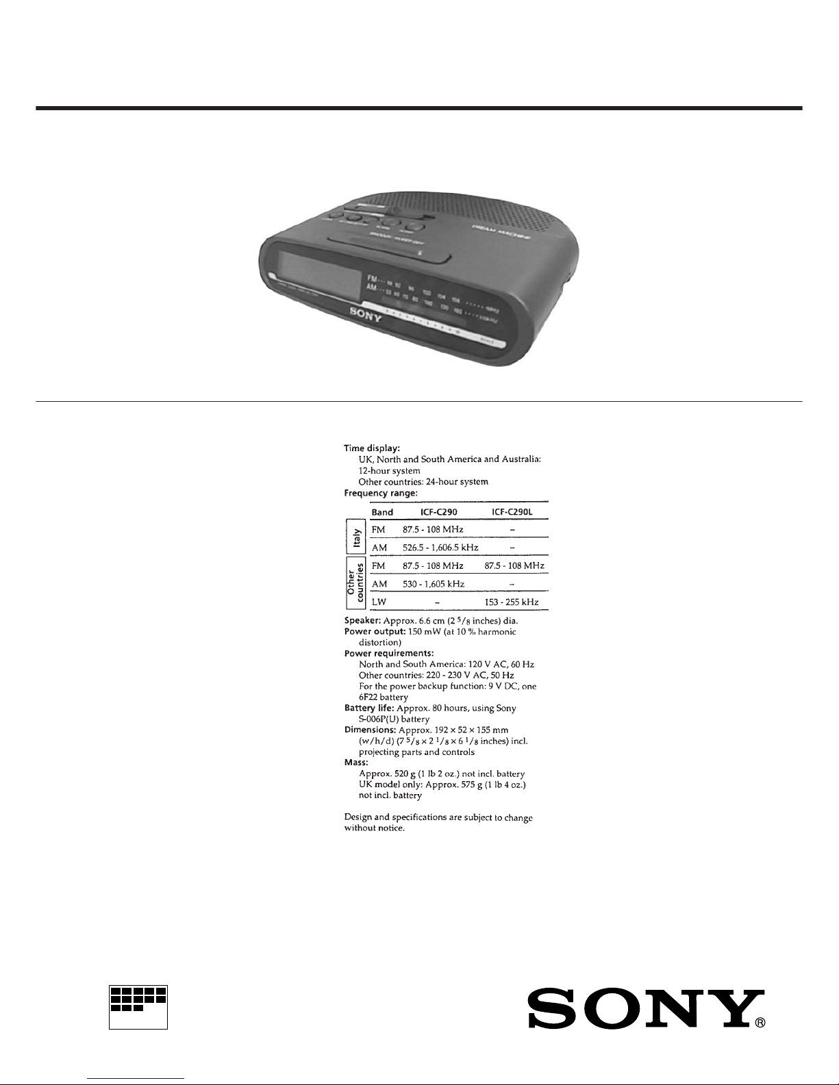
SPECIFICATIONS
SERVICE MANUAL
ICF-C290/C290L
Photo: ICF-C290
Ver 1.1 1998. 10
With SUPPLEMENT 1
(9-925-745-81)
– 2 –
Notes on chip component replacement
• Never reuse a disconnected chip component.
• Notice that the minus side of a tantalum capacitor may be damaged by heat.
SAFETY-RELATED COMPONENT WARNING!!
COMPONENTS IDENTIFIED BY MARK ! OR DOTTED
LINE WITH MARK ! ON THE SCHEMATIC DIAGRAMS
AND IN THE PARTS LIST ARE CRITICAL TO SAFE
OPERATION. REPLACE THESE COMPONENTS WITH
SONY PARTS WHOSE PART NUMBERS APPEAR AS
SHOWN IN THIS MANUAL OR IN SUPPLEMENTS PUBLISHED BY SONY.
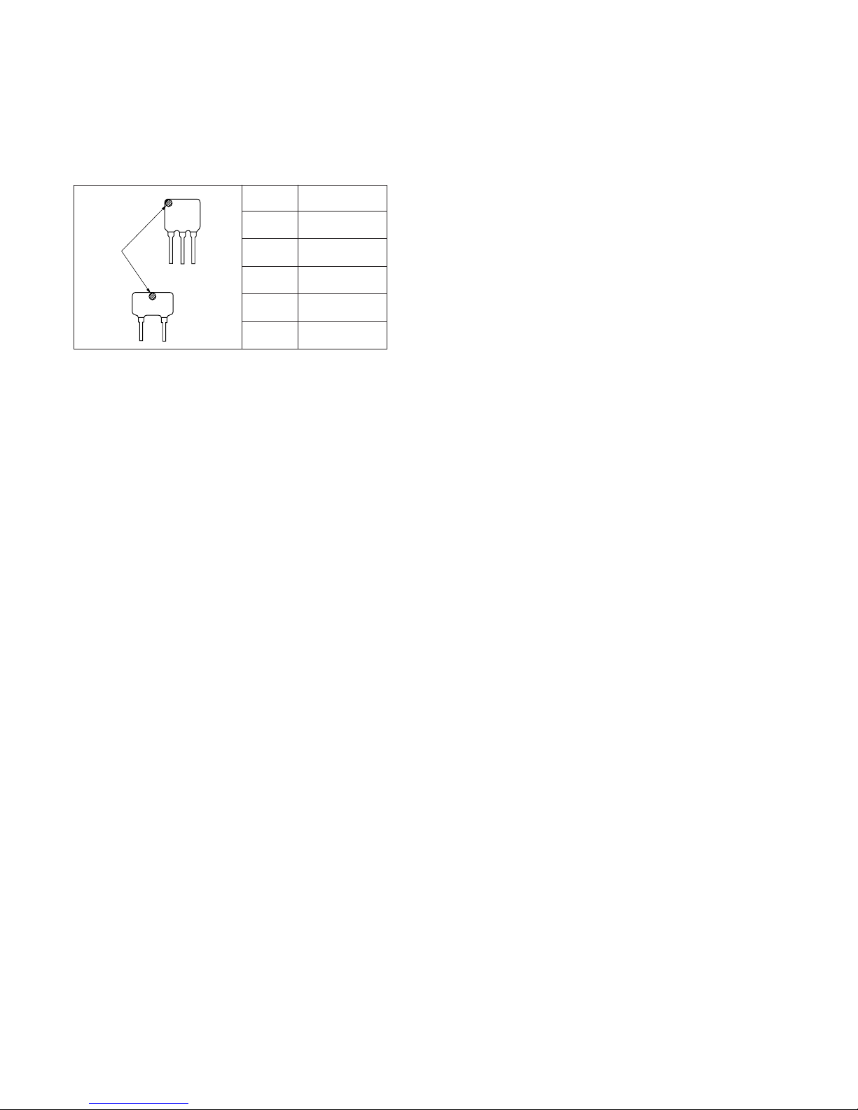
CF
2
CF3
mark
Mark Center frequency
red 10.70 MHz
blue 10.67 MHz
orange 10.73 MHz
black 10.64 MHz
white 10.76 MHz
HOW TO CHANGED THE CERAMIC FILTERS
This model is used two ceramic filters of CF2 and CF3.
You must used same type of color marked ceramic filters in order
to meet same specifications.
Therefore, the ceramic filter must changed two pieces together
since it's supply two pieces in one package as a spare parts.
SER VICING NOTES
– 3 –
SECTION 1
GENERAL
This section is extracted from
instruction manual.
– 4 –
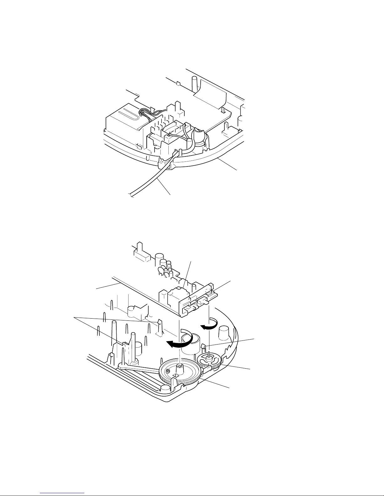
Set the power cord as illustrated below, then install the lower cabinet.
SETTING THE POWER CORD
SECTION 2
SETTING
KNOB SETTING
7
claws
5
MAIN board
3
Turn shaft of CV1 to the
arrow A direction fully.
4
Turn RV1 to the arrow B
direction fully.
6
claw
2
Turn the knob (VOL) to the
arrow B direction fully.
1
Turn the knob (tuning) to the
arrow A direction fully.
A
B
lower cabine
t
power cord
 Loading...