

Page 1
ICF-8/8L
SERVICE MANUAL
Ver 1.3 2000. 10
With SUPPLEMENT-1
(9-924-922-81)
With SUPPLEMENT-2
(9-924-922-82)
With SUPPLEMENT-3
(9-924-922-83)
Photo: ICF-8
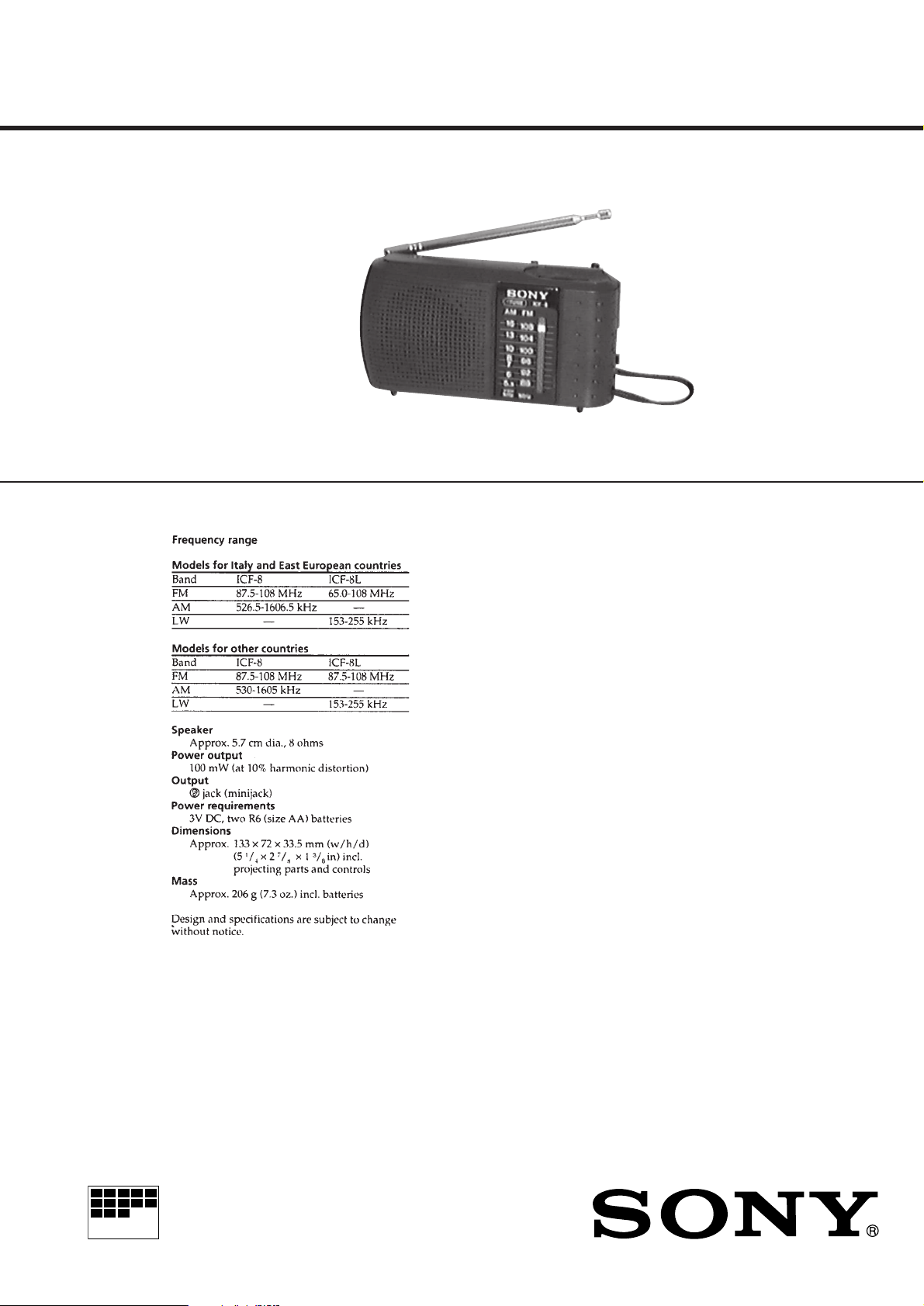
SPECIFICATIONS
AEP Model
UK Model
ICF-8/8L
E Model
ICF-8
Notes on chip component replacement
• Never reuse a disconnected chip component.
• Notice that the minus side of a tantalum capacitor may be damaged by
heat.
MICROFILM
ICF-8
FM/AM RADIO
ICF-8L
FM/LW RADIO
Page 2
This section is extracted from
instruction manual.
SECTION 1
GENERAL
– 2 –
Page 3
SECTION 2
)
DISASSEMBLY
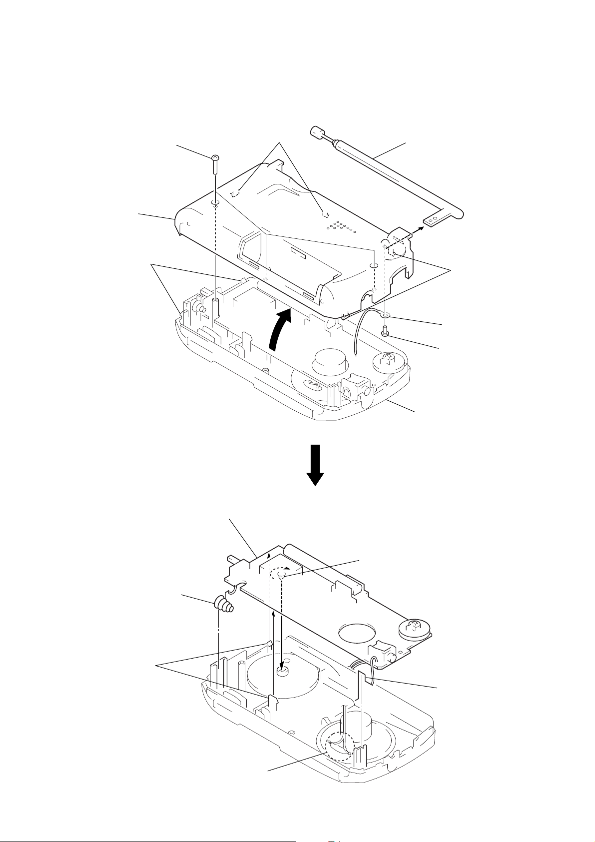
Note: Follow the disassembly procedure in the numerical order given.
CABINET (REAR)
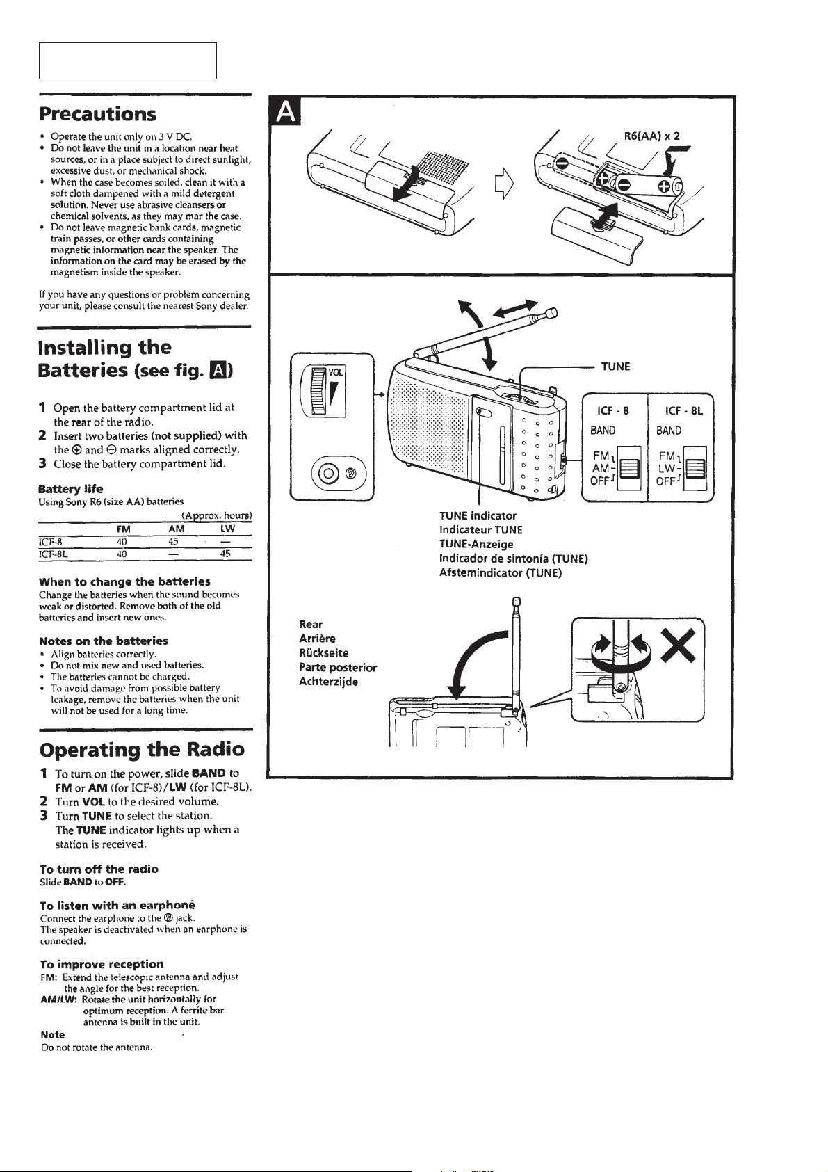
1
Remove the battery lid.
3
two claws
4
8
cabinet (rear)
3
2
three screws
(P2 × 8)
two claws
telescopic antenna
7
3
6
5
screw (B1.7 × 4
two claws
lug
MAIN BOARD
2
battery terminal (–)
4
two claws
5
MAIN board
A
CV1
9
cabinet (front)
Note:On installation MAIN board,
turn CV1 shaft in the arrow A
direction fully.
3
battery terminal (+)
1
Remove two solders
of the speaker leads.
– 3 –
Page 4
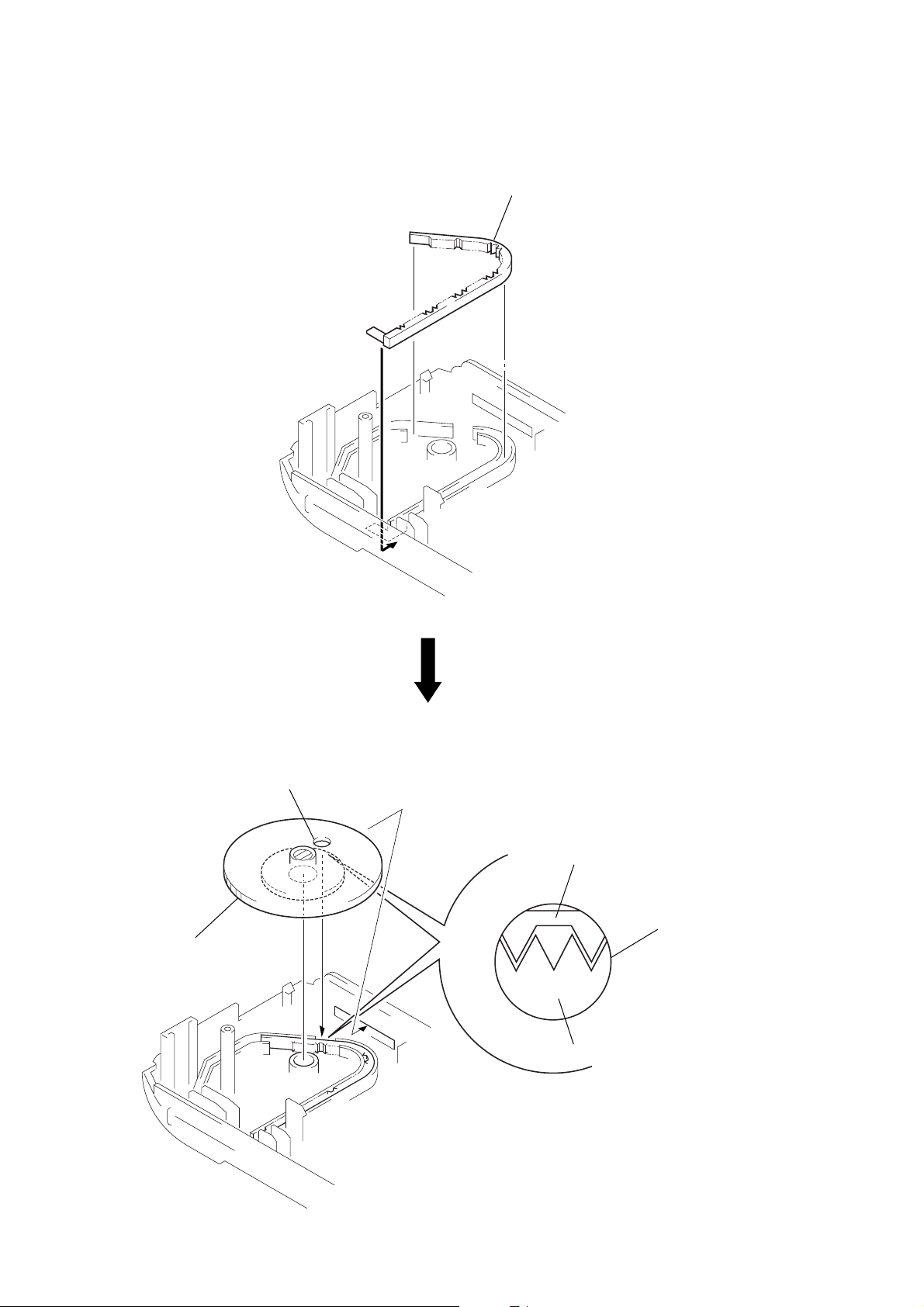
DIAL POINTER SETTING
Note: Follow the assembly procedure in the numerical order given.
• POINTER
1
pointer
• KNOB (TUNE)
5
knob (TUNE)
hole
3
pointer
hole
knob (TUNE)
4
Insert the knob (TUNE) to the pointer
fitting the two gear portion of the knob (TUNE)
to the concave portion of the pointer.
– 4 –
Page 5

SECTION 3
r
r
CF2
CF3
mark
ELECTRICAL ADJUSTMENTS
SECTION 4
DIAGRAMS
PRECAUTION
• Adjustment should be performed in the order given.
0 dB=1 µV
[FM]
Setting:
BAND switch: FM
FM RF signal
generator
FM antenna IN
0.01
µ
F
set
22.5 kHz frequency
deviation by
400 Hz signal.
Output level: as low as possible
earphone jack (J1)
[AM/LW]
Setting:
BAND switch: AM/LW
AM RF signal
generator
30% amplitude
modulation by
400 Hz signal
Output level: as low as possible
Put the lead-wire
antenna close to
the set.
set
32
earphone jack (J1)
• Repeat the procedures in each adjustment several times, and the
frequency coverage and tracking adjustments should be finally
done by the trimmer capacitors.
32
Ω
level mete
Ω
+
–
level mete
+
–
( ): Italian model, [ ]: East European model
FM FREQUENCY COVERAGE ADJUSTMENT
Adjust for a maximum reading on level meter.
L3 86.5 MHz (87.35 MHz) [64.0 MHz]
CT3 109.5 MHz (108.25 MHz) [109.5 MHz]
FM TRACKING ADJUSTMENT
Adjust for a maximum reading on level meter.
L2 86.5 MHz (87.35 MHz) [64.0 MHz]
CT2 109.5 MHz (108.25 MHz) [109.5 MHz]
AM IF ADJUSTMENT
Adjust for a maximum reading on level meter.
T1 455 kHz
AM FREQUENCY COVERAGE ADJUSTMENT (ICF-8)
Adjust for a maximum reading on level meter.
L4 520 kHz (516.5 kHZ)
CT4 1,650 kHz (1,631.5 kHz)
AM TRACKING ADJUSTMENT (ICF-8)
Adjust for a maximum reading on level meter.
L1 620 kHz
CT1 1,400 kHz
LW FREQUENCY COVERAGE ADJUSTMENT (ICF-8L)
Adjust for a maximum reading on level meter.
L4 145 kHz
CT6 265 kHz
LW TRACKING ADJUSTMENT (ICF-8L)
Adjust for a maximum reading on level meter.
L1 160 kHz
CT5 240 kHz
• IC Block Diagram
IC1 CXA1019M
FM/AM
IF OUT
14 13
15
SELECT
FM/AM BAND
FE GND
16
AM IF IN
FM RF IN
12
FM IF
17
FM IF IN
AM RF IN
NC
11
TUNING METER
18
NC
FM RF
10 9 8 7 2 16 5 34
20
19
IF GND
METER
FM OSC
REG OUT
FM FE
FM
DISCRIMINATOR
AM FE
AM IF DET AGC
21
22
AFC AGC
AFC AGC
AFC
23
DET OUT
AM OSCNFVOL
24
AF IN
25
RIPPLE FILTER
HOW TO CHANGED THE CERAMIC FILTERS
This model is used two ceramic filters of CF2 and CF3.
You must used same type of color marked ceramic filters in order
to meet same specifications.
Therefore, the ceramic filter must changed two pieces together
since it’s supply two pieces in one package as a spare parts.
Mark Center frequency
red 10.70 MHz
AF POWER AMP
26
27
VCC
FM DISCRI
28
AF OUT
GND
GND
Adjustment Location: MAIN board (Component Side)
L1
CT1
LW Frequency
Coverage
Adjustment
AM Frequency
Coverage
Adjustment
AM Tracking
Adjustment
CT6
L4
L4
CT4
L1
CT5
CT2
L2
LW Tracking
Adjustment
FM Tracking
Adjustment
T1
AM IF
Adjustment
CT3
L3
FM Frequency
Coverage
Adjustment
FM Antenna IN
J1
blue 10.67 MHz
orange 10.73 MHz
black 10.64 MHz
white 10.76 MHz
– 5 – – 6 –
Page 6

Page 7

Page 8

SECTION 5
EXPLODED VIEW
MAIN
SECTION 6
ELECTRICAL PARTS LIST
NOTE:
• -XX and -X mean standardized parts, so they
may have some difference from the original
one.
• Color Indication of Appearance Par ts
Example:
KNOB, BALANCE (WHITE) . . . (RED)
↑↑
Parts Color Cabinet's Color
• Abbreviation
EE : East European
FR : French
IT : Italian
• Items marked “*” are not stocked since they
are seldom required for routine service. Some
delay should be anticipated when ordering
these items.
• The mechanical parts with no reference number in the exploded views are not supplied.
• Accessories and packing materials are given
in the last of the electrical parts list.
10
6
9
7
3
SP1
2
4
5
1
Ref. No. Part No. Description Remark
1 3-027-092-01 PLATE, TRANSPARENT (ICF-8)
1 3-027-092-11 PLATE, TRANSPARENT (FR)
1 3-027-092-21 PLATE, TRANSPARENT (EE)
2 3-027-089-01 CABINET (FRONT) (ICF-8)
2 3-027-089-11 CABINET (FRONT) (ICF-8L)
3 3-027-106-01 TERMINAL (+), BATTERY
4 3-027-096-01 POINTER
5 3-027-093-01 KNOB (TUNE)
* 6 A-3683-011-A MAIN BOARD, COMPLETE (AEP, UK, E)
* 6 A-3683-012-A MAIN BOARD, COMPLETE (IT)
* 6 A-3683-013-A MAIN BOARD, COMPLETE (FR)
* 6 A-3683-014-A MAIN BOARD, COMPLETE (EE)
7 3-027-094-01 KNOB (VOL)
ANT1
11
8
15
14
13
16
Ref. No. Part No. Description Remark
8 3-027-095-01 HOLDER (FERRITE-ROD ANTENNA)
9 3-318-203-61 SCREW (B1.7X4), TAPPING
10 7-623-505-01 LUG, 2
11 3-027-090-01 CABINET (REAR)
12 7-685-105-14 TAPPING +P 2X8 NON-SLIT
13 3-027-091-01 LID, BATTERY CASE
14 3-027-108-01 CUSHION (BATTERY)
15 3-027-107-01 TERMINAL (-), BATTERY
16 3-893-381-01 STRAP, HAND
ANT1 1-501-247-21 ANTENNA, TELESCOPIC
L1 1-754-018-11 ANTENNA, FERRITE-ROD (LW) (ICF-8L)
L1 1-754-019-11 ANTENNA, FERRITE-ROD (MW) (ICF-8)
SP1 1-503-616-11 SPEAKER
12
L1
NOTE:
• Due to standardization, replacements in the
parts list may be different from the parts specified in the diagrams or the components used
on the set.
• -XX and -X mean standardized parts, so they
may have some difference from the original
one.
• RESISTORS
All resistors are in ohms.
METAL: Metal-film resistor.
METAL OXIDE: Metal oxide-film resistor.
F: nonflammable
Ref. No. Part No. Description Remark Ref. No. Part No. Description Remark
* A-3683-011-A MAIN BOARD, COMPLETE (AEP, UK, E)
* A-3683-012-A MAIN BOARD, COMPLETE (IT)
* A-3683-013-A MAIN BOARD, COMPLETE (FR)
* A-3683-014-A MAIN BOARD, COMPLETE (EE)
*********************
3-027-094-01 KNOB (VOL)
3-027-095-01 HOLDER (FERRITE-ROD ANTENNA)
< CAPACITOR >
C1 1-163-141-00 CERAMIC CHIP 0.001uF 5% 50V
C2 1-161-051-00 CERAMIC 0.01uF 10% 50V
C2 1-161-055-00 CERAMIC 0.022uF 10% 50V
C3 1-104-664-11 ELECT 47uF 20% 16V
C4 1-163-106-00 CERAMIC CHIP 36PF 5% 50V
C4 1-163-235-11 CERAMIC CHIP 22PF 5% 50V
C4 1-163-237-11 CERAMIC CHIP 27PF 5% 50V
C5 1-163-091-00 CERAMIC CHIP 8PF 50V
C5 1-163-235-11 CERAMIC CHIP 22PF 5% 50V
C5 1-163-237-11 CERAMIC CHIP 27PF 5% 50V
C6 1-163-097-00 CERAMIC CHIP 15PF 5% 50V
C6 1-163-104-00 CERAMIC CHIP 30PF 5% 50V
C6 1-163-106-00 CERAMIC CHIP 36PF 5% 50V
C7 1-163-021-00 CERAMIC CHIP 0.01uF 10% 50V
C8 1-126-963-11 ELECT 4.7uF 20% 50V
C9 1-163-021-00 CERAMIC CHIP 0.01uF 10% 50V
C10 1-126-963-11 ELECT 4.7uF 20% 50V
C11 1-126-963-11 ELECT 4.7uF 20% 50V
C12 1-124-907-11 ELECT 10uF 20% 50V
C13 1-163-038-00 CERAMIC CHIP 0.1uF 25V
C14 1-161-051-00 CERAMIC 0.01uF 10% 50V
C14 1-161-055-00 CERAMIC 0.022uF 10% 50V
C15 1-124-907-11 ELECT 10uF 20% 50V
C16 1-126-925-11 ELECT 470uF 20% 10V
• Items marked “*” are not stocked since they
are seldom required for routine service.
Some delay should be anticipated when ordering these items.
• SEMICONDUCTORS
In each case, u: µ, for example:
uA. . : µA. . uPA. . : µPA. .
uPB. . : µPB. . uPC. . : µPC. .
uPD. . : µPD. .
• CAPACITORS
uF: µF
• COILS
uH: µH
C17 1-164-346-11 CERAMIC CHIP 1uF 16V
C18 1-164-346-11 CERAMIC CHIP 1uF 16V
C18 1-164-505-11 CERAMIC CHIP 2.2uF 16V
C19 1-104-666-11 ELECT 220uF 20% 6.3V
C20 1-163-251-11 CERAMIC CHIP 100PF 5% 50V
C21 1-163-222-11 CERAMIC CHIP 5PF 0.25PF 50V
C21 1-163-235-11 CERAMIC CHIP 22PF 5% 50V
(ICF-8)
(ICF-8L)
(EE)
(EXCEPT IT, EE)
(IT)
(EE)
(EXCEPT IT, EE)
(IT)
(EE)
(EXCEPT IT, EE)
(IT)
(ICF-8L)
(ICF-8)
C22 1-163-093-00 CERAMIC CHIP 10PF 5% 50V
C22 1-163-121-00 CERAMIC CHIP 150PF 5% 50V
C23 1-163-021-00 CERAMIC CHIP 0.01uF 10% 50V
C24 1-163-141-00 CERAMIC CHIP 0.001uF 5% 50V
C25 1-163-141-00 CERAMIC CHIP 0.001uF 5% 50V
CF1 1-577-072-11 FILTER, CERAMIC (ICF-8)
CF1 1-781-035-11 FILTER, CERAMIC (ICF-8L)
CF2 1-579-632-51 FILTER, CERAMIC
CF3 1-579-632-51 FILTER, CERAMIC
CV1 1-141-497-11 CAP, VAR (TUNE) (EXCEPT EE)
CV1 1-141-498-11 CAP, VAR (TUNE) (EE)
CT1-4 1-141-497-11 CAP, VAR (EXCEPT EE)
CT1-4 1-141-498-11 CAP, VAR (EE)
CT5 1-141-604-11 CAP, ADJ (ICF-8L)
CT6 1-141-604-11 CAP, ADJ (ICF-8L)
D1 8-719-991-33 DIODE 1SS133T-77
D2 8-719-991-33 DIODE 1SS133T-77
D3 8-719-059-87 DIODE SLR-342VRTB7 (TUNE)
IC1 8-752-050-16 IC CXA1019M
When indicating parts by reference
number, please include the board.
• Abbreviation
EE : East European
FR : French
IT : Italian
< FILTER >
< VARIABLE CAPACITOR >
< DIODE >
< IC >
(ICF-8)
(ICF-8L)
(ICF-8)
(ICF-8L)
(ICF-8)
(ICF-8L)
(ICF-8L)
– 11 –
– 12 –
Page 9

MAIN
Ref. No. Part No. Description Remark
< JACK >
J1 1-770-666-11 JACK (@)
< COIL >
L1 1-754-018-11 ANTENNA, FERRITE-ROD (LW) (ICF-8L)
L1 1-754-019-11 ANTENNA, FERRITE-ROD (MW) (ICF-8)
L2 1-416-799-11 COIL, AIR-CORE (EXCEPT EE)
L2 1-416-800-11 COIL, AIR-CORE (EE)
L3 1-422-131-00 COIL, FM OSCILLATION (EXCEPT IT, EE)
L3 1-428-768-11 COIL, AIR-CORE (EE)
L3 1-460-018-11 COIL (WITH CORE)( IT)
L4 1-406-028-00 COIL, OSC (MW)
L5 1-416-459-11 COIL, AIR-CORE
L6 1-410-294-11 INDUCTOR 38uH (ICF-8L)
< RESISTOR >
R1 1-216-057-00 METAL CHIP 2.2K 5% 1/10W
R2 1-216-045-00 METAL CHIP 680 5% 1/10W
R3 1-216-053-00 METAL CHIP 1.5K 5% 1/10W
R4 1-216-013-00 METAL CHIP 33 5% 1/10W
R6 1-216-057-00 METAL CHIP 2.2K 5% 1/10W
(ICF-8L)
R7 1-216-061-00 METAL CHIP 3.3K 5% 1/10W
(EXCEPT IT)
R9 1-216-071-00 METAL CHIP 8.2K 5% 1/10W
R10 1-216-063-00 RES, CHIP 3.9K 5% 1/10W
Ref. No. Part No. Description Remark
< VARIABLE RESISTOR >
RV1 1-225-441-41 RES, VAR, CARBON 50K (VOL)
< SWITCH >
S1 1-572-633-11 SWITCH, SLIDE (BAND)
< TRANSFORMER >
T1 1-404-790-11 TRANSFORMER, IF (ICF-8)
T1 1-404-902-11 TRANSFORMER, IF (ICF-8L)
************************************************************
MISCELLANEOUS
***************
ANT1 1-501-247-21 ANTENNA, TELESCOPIC
SP1 1-503-616-11 SPEAKER
************************************************************
ACCESSORIES & PACKING MATERIALS
********************************
3-864-359-11 MANUAL, INSTRUCTION (ENGLISH, FRENCH,
GERMAN, SPANISH, DUTCH, ITALIAN,
PORTUGUESE, RUSSIAN, CHINESE)
– 13 –
Page 10

ICF-8/8L
9-924-922-11
Sony Corporation
Personal A&V Products Company
– 14 –
Printed in Japan © 1998. 6
98F0565-1
Published by Quality Engineering Dept.
(Shibaura)
Page 11

ICF-8
/
8L
AEP Model
UK Model
ICF-8/8L
SERVICE MANUAL
1998. 09
E Model
SUPPLEMENT-1
File this supplement with the service manual.
Subject: Addition of Silver Color Model
(ENG-98006)
• EXPLODED VIEWS (Service Manual see page 11)
Before change After change
Ref. No Part No. Description Remark Part No. Description Remark
2 3-027-089-01 CABINET (FRONT) (ICF-8)
11 3-027-090-01 CABINET (REAR)
3-027-089-01 CABINET (FRONT) (DARK GRAY) (ICF-8)
3-027-089-31 CABINET (FRONT) (SILVER) (ICF-8 : AEP, UK)
3-027-090-01 CABINET (REAR) (DARK GRAY)
3-027-090-21 CABINET (REAR) (SILVER) (ICF-8 : AEP, UK)
ICF-8
13 3-027-091-01 LID, BATTERY CASE
3-027-091-01 LID, BATTERY CASE (DARK GRAY)
3-027-091-21 LID, BATTERY CASE (SILVER) (ICF-8 : AEP, UK)
Sony Corporation
Personal A&V Products Company
Printed in Japan © 1998. 9
98I0534-1D
Published by Quality Engineering Dept.
(Shibaura)9-924-922-81
Page 12

ICF-8/8L
AEP Model
UK Model
ICF-8/8L
SERVICE MANUAL
2000. 03
SUPPLEMENT-2
File this supplement with the service manual.
Subject: Addition of ICF-8 (6E) ORANGE Color Model
• EXPLODED VIEWS (Supplement-1 see page 1)
Before Change After Change
Ref. No. Part No. Description Remark
1
2 3-027-089-01 CABINET (FRONT) (DARK GRAY) (ICF-8)
3-027-089-31 CABINET (FRONT) (SILVER) (ICF-8: AEP, UK)
4
E Model
ICF-8
(ENG-00003)
Part No. Description Remark
3-027-092-51 PLATE, TRANSPARENT (ICF-8: 6E)
3-027-089-01 CABINET (FRONT) (DARK GRAY) (ICF-8)
3-027-089-31 CABINET (FRONT) (SILVER) (ICF-8: AEP, UK)
3-027-089-41 CABINET (FRONT) (ORANGE) (ICF-8: 6E)
3-027-096-11 POINTER (ORANGE) (ICF-8: 6E)
11 3-027-090-01 CABINET (REAR) (DARK GRAY)
3-027-090-21 CABINET (REAR) (SILVER) (ICF-8: AEP, UK)
13 3-027-091-01 LID, BATTERY CASE (DARK GRAY)
3-027-091-21 LID, BATTERY CASE (SILVER) (ICF-8: AEP, UK)
3-027-090-01 CABINET (REAR) (DARK GRAY)
3-027-090-21 CABINET (REAR) (SILVER) (ICF-8: AEP, UK)
3-027-090-31 CABINET (REAR) (ORANGE) (ICF-8: 6E)
3-027-091-01 LID, BATTERY CASE (DARK GRAY)
3-027-091-11 LID, BATTERY CASE (ORANGE) (ICF-8: 6E)
3-027-091-21 LID, BATTERY CASE (SILVER) (ICF-8: AEP, UK)
9-924-922-82
Sony Corporation
Personal Audio Division Company
Printed in Japan C 2000. 3
2000C0566-1
Published by General Engineering Dept.
Page 13

ICF-8/8L
AEP Model
UK Model
ICF-8/8L
SERVICE MANUAL
2000. 10
SUPPLEMENT-3
File this supplement with the service manual.
Subject: Addition of ICF-8 (E, 6E) Silver Color Model
• EXPLODED VIEWS (Supplement-2 see page 1)
Before Change After Change
Ref. No. Part No. Description Remark
2 3-027-089-31 CABINET (FRONT) (SILVER) (ICF-8: AEP, UK)
11 3-027-090-21 CABINET (REAR) (SILVER) (ICF-8: AEP, UK)
13 3-027-091-21 LID, BATTERY CASE (SILVER) (ICF-8: AEP, UK)
E Model
ICF-8
(ENG-00017)
Part No. Description Remark
3-027-089-31 CABINET (FRONT) (SILVER) (ICF-8: AEP, UK, E, 6E)
3-027-090-21 CABINET (REAR) (SILVER) (ICF-8: AEP, UK, E, 6E)
3-027-091-21 LID, BATTERY CASE (SILVER) (ICF-8: AEP, UK, E, 6E)
9-924-922-83
Sony Corporation
Audio Entertainment Group
Printed in Japan C 2000. 10
2000J0515-1D
Published by General Engineering Dept.
 Loading...