

Page 1
ICF-18
SERVICE MANUAL
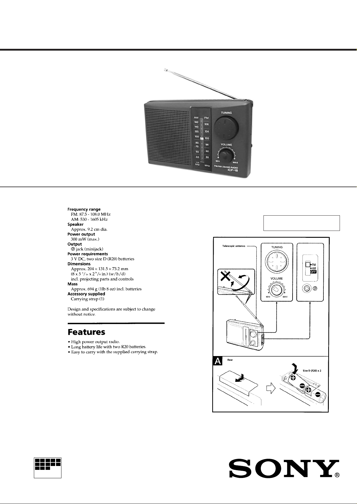
SPECIFICATIONS
US Model
Canadian Model
AEP Model
UK Model
E Model
Austr alian Model
SECTION 1
GENERAL
This section is extracted from
instruction manual.
MICROFILM
FM/AM RADIO
Page 2
SECTION 2
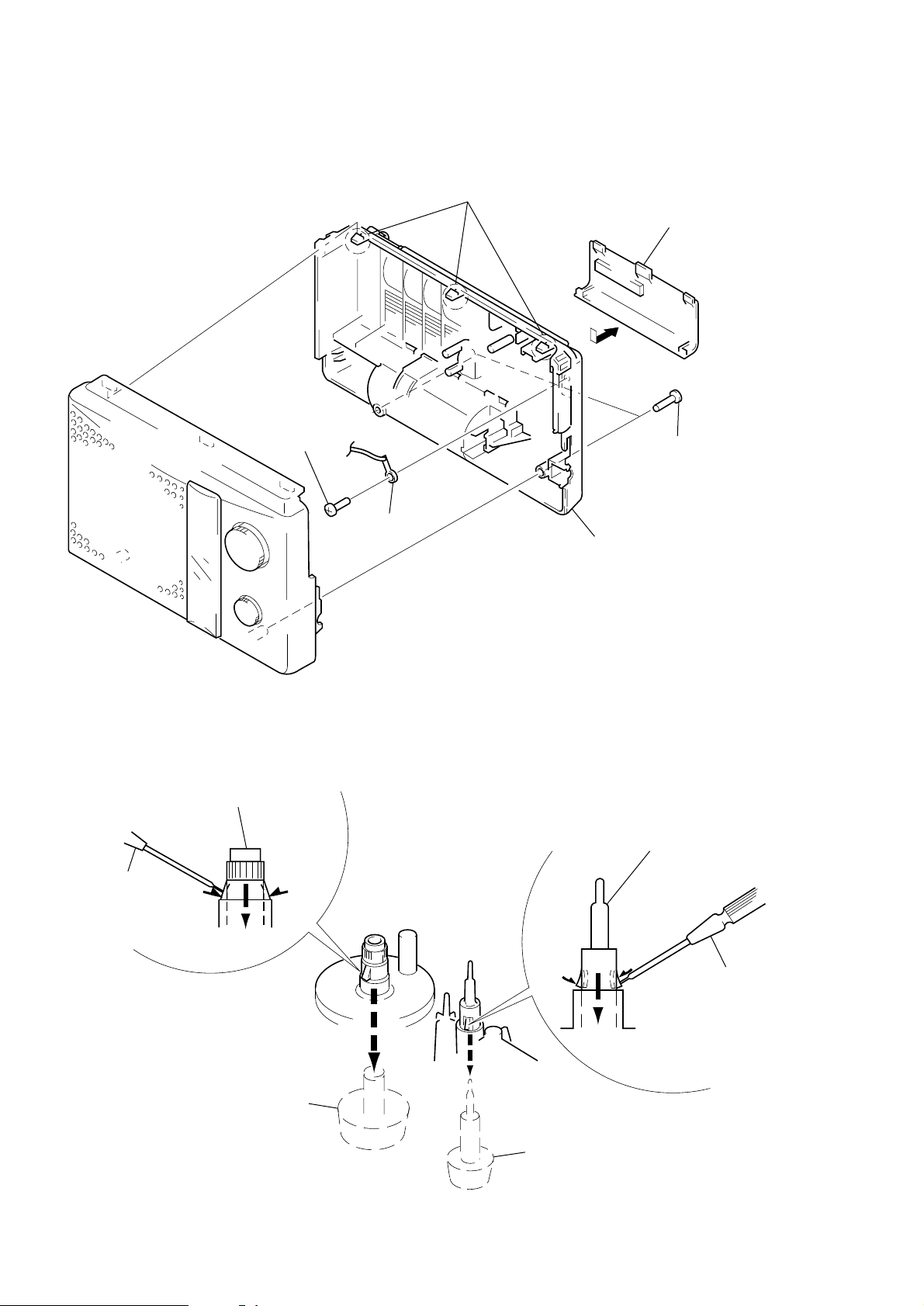
DISASSEMBLY
Note: Follow the disassembly procedure in the numerical order given.
CABINET (REAR)
5
screw
(P 3
×
10)
3
three claws
1
Remove the battery case lid
to direction of the arrow.
2
two screws
×
14)
(P 3
KNOB (VOL), KNOB (TUNE)
knob (tune)
screw
driver
1
two claws
6
lug
4
cabinet (rear)
knob (vol)
screw
driver
2
knob (tune)
– 2 –
2
knob (vol)
1
two claws
Page 3
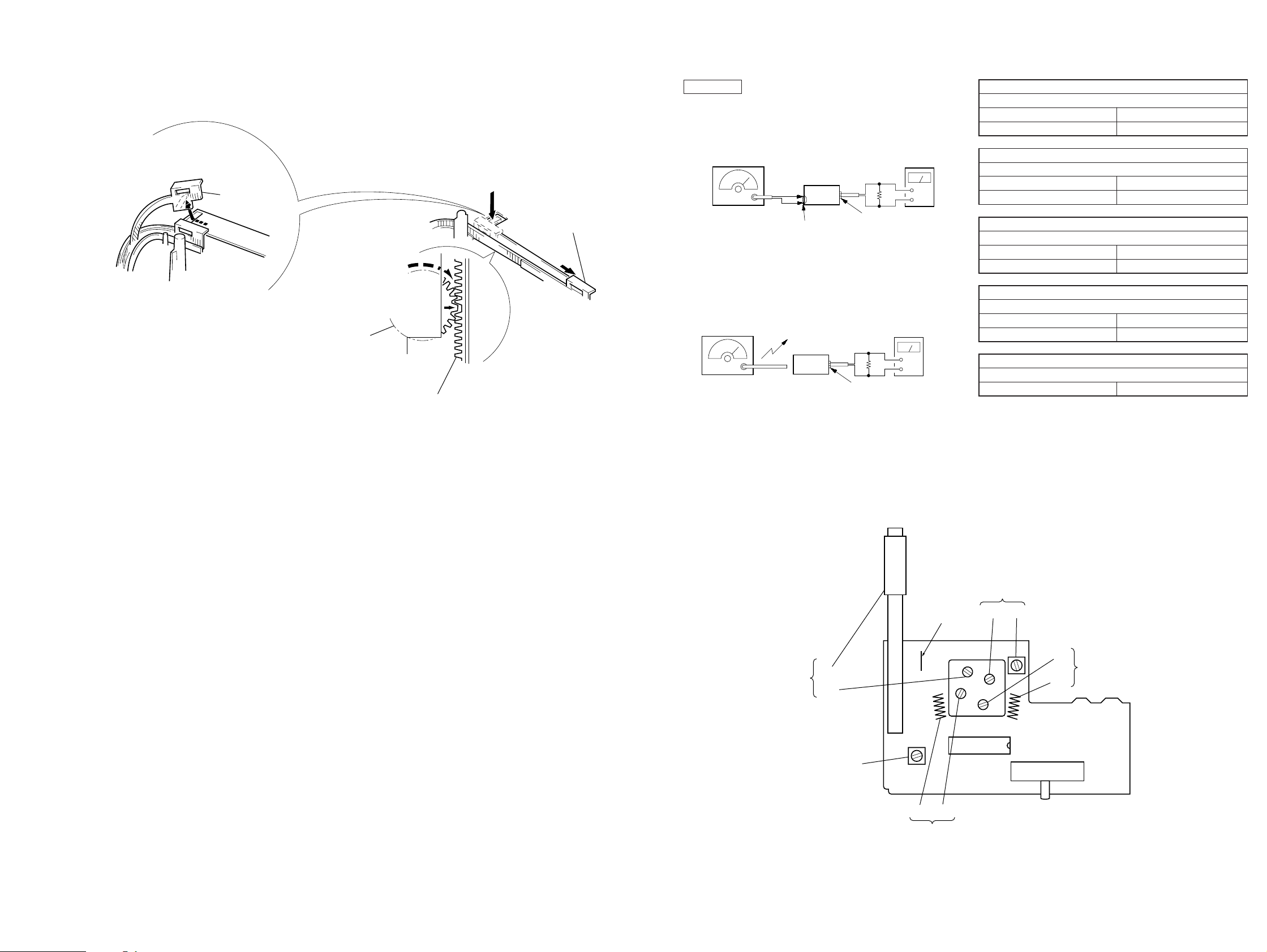
SECTION 3
g
FM RF SSG
±
22.5 kHz frequency
deviation by 400 Hz
signal
Output level: as low as possible
+
–
level meter
earphone jack
set
FM antenna terminal
8
Ω
r
DIAL POINTER SETTING
SECTION 4
ELECTRICAL ADJUSTMENTS
Note: Follow the assembly procedure in the numerical order given.
Note: When take off the pointer,
remove to direction of the arrow
pointer
A
A
.
2
Turn the VC gear
fully in the arrow
direction.
B
B
3
Insert the pointer to the gear
fitting the concave position
of the pointer to the convex
position of the
ear.
1
Slide the pointer
to the inner part.
0dB=1 µV
[FM Section]
Setting:
Band select switch: FM
[AM Section]
Setting:
Band select switch: AM
Put the lead-wire
AM RF SSG
30% amplitude
modulation by
400 Hz signal
Output level: as low as possible
antenna close to
the set.
set
8
Ω
earphone jack
level mete
+
–
Repeat the procedures in each adjustment several times, and the
frequency coverage and tracking adjustments should be finally done
by the trimmer capacitors.
FM FREQUENCY COVERAGE ADJUSTMENT
Adjust for a maximum reading on level meter.
L3 75.0 MHz
CT1 109.5 MHz
FM TRACKING ADJUSTMENT
Adjust for a maximum reading on level meter.
L2 75.0 MHz
CT2 109.5 MHz
AM FREQUENCY COVERAGE ADJUSTMENT
Adjust for a maximum reading on level meter.
L4 520 kHz
CT3 1,650 kHz
AM TRACKING ADJUSTMENT
Adjust for a maximum reading on level meter.
L1 600 kHz
CT4 1,400 kHz
AM IF ADJUSTMENT
Adjust for a maximum reading on level meter.
T1 455 kHz
Adjustment Location: MAIN board (Component Side)
AM
TRACKING
L1
JW4
CT4
T1
AM IF
L2 CT2
FM TRACKING
FM
antenna
terminal
AM FREQUENCY
COVERAGE
CT3 L4
IC1
BAND SELECT
(
SWITCH
FM
↔AM↔
S1
CT1
FM FREQUENCY
L3
COVERAGE
)
OFF
– 3 –
– 4 –
Page 4

2
ICF-18
SECTION 5
DIAGRAMS
5-1. SCHEMATIC DIAGRAM
Note on Schematic Diagram:
• All capacitors are in µF unless otherwise noted. pF: µµF 50
WV or less are not indicated except for electrolytics and
tantalums.
• All resistors are in Ω and 1/
specified.
W or less unless otherwise
4
• ¢ : internal component.
• : panel designation.
• : B+ Line.
• : adjustment for repair.
• Power voltage is dc 3 V and fed with regulated dc power
supply from battery terminal.
• Voltages are dc with respect to ground under no-signal
(detuned) conditions.
no mark : FM
( ) : AM
[ ] : FM/AM
• Voltages are taken with a VOM (Input impedance 10 MΩ).
V oltage variations may be noted due to normal production
tolerances.
• Signal path.
: FM
• IC Block Diagram
IC1 CXA1019S
GND
GND
AF OUT
VCC
RIPPLE
FILTER
AF IN
DET OUT
AFC AGC
AFC AGC
FM FE
FM OSC
REG OUT
IF GND
TUNING
FM RF
23 22 21 202425 19 18 17 1629 28 27 2630
AM IF DET AGC
AF POWER AMP AM FE FM IF
FM
DISCRIMINATOR
2 345 6 7 8 9 10 1514131211
1
GND
GND
NF
FM DISCRI
VOL
AFC
AM OSC
METER
METER
AM RF IN
N.C
N.C
FM IF IN
FE GND
FM RF IN
AM IF IN
FM/AM BAND
SELECT
IF OUT
FM/AM
5-2. PRINTED WIRING BOARDS
HOW TO CHANGE THE CERAMIC FILTERS
This model is used two ceramic filters of CF2, CF3.
Y ou must use same type of color marked cer amic filters in order to
meet same specifications.
Therefore, the ceramic filter must change two pieces together since
it's supply two pieces in one package as a spare parts.
Mark Center frequency
CF
mark
CF3
red 10.70 MHz
blue 10.67 MHz
orange 10.73 MHz
black 10.64 MHz
white 10.76 MHz
– 5 –
Note on Printed Wiring Board:
• : parts extracted from the component side .
• p : parts mounted on the conductor side.
• ¢ : internal component.
• : Pattern from the side which enables seeing.
– 6 –
Page 5

SECTION 6
EXPLODED VIEW
NOTE:
• -XX and -X mean standardized parts, so they
may have some difference from the original
one.
• Color Indication of Appearance Parts
Example:
KNOB, BALANCE (WHITE) . . . (RED)
↑↑
Parts Color Cabinet's Color
5
SP1
• Items marked “*” are not stocked since they
are seldom required for routine service. Some
delay should be anticipated when ordering
these items.
• The mechanical parts with no reference number in the exploded views are not supplied.
• Hardware (# mark) list and accessories and
packing materials are given in the last of the
electrical parts list.
ANT1
6
#3
not supplied
#1
#2
7
12
not supplied
8
9
2
3
4
11
1
10
Ref. No. Part No. Description Remark
1 3-017-750-01 PLATE, TRANSPARENT
2 3-017-752-01 KNOB (TUNE)
3 3-017-753-01 KNOB (VOL)
4 3-017-749-01 CABINET (FRONT)
5 3-920-194-01 TERMINAL (–), BATTERY
6 3-017-751-01 POINTER
7 3-920-185-01 CABINET (REAR)
8 3-905-428-11 LID, BATTERY CASE
Ref. No. Part No. Description Remark
* 9 A-3662-892-A MAIN BOARD, COMPLETE (US)
* 9 A-3679-659-A MAIN BOARD, COMPLETE (EXCEPT US)
10 3-920-188-01 GEAR, VC
11 3-925-513-01 SHEET (BAND)
* 12 1-656-281-11 POSITIVE TERMINAL BOARD
ANT1 1-501-774-11 ANTENNA, TELESCOPIC (FM)
SP1 1-504-861-11 SPEAKER (9.2CM)
– 7 –
Page 6

MAIN
SECTION 7
ELECTRICAL PARTS LIST
NOTE:
• Due to standardization, replacements in the
parts list may be different from the parts specified in the diagrams or the components used on
the set.
• -XX and -X mean standardized parts, so they
may have some difference from the original one.
• RESISTORS
All resistors are in ohms.
METAL: Metal-film resistor.
METAL OXIDE: Metal oxide-film resistor.
F: nonflammable
Ref. No. Part No. Description Remark
* A-3662-892-A MAIN BOARD, COMPLETE (US)
* A-3679-659-A MAIN BOARD, COMPLETE
(Canadian, AEP, UK, E, AUS)
*********************
< CAP ACIT OR >
C 1 1-102-945-00 CERAMIC 8.0PF ±0.5PF 50V
C 2 1-101-004-00 CERAMIC 0.01uF 50 V
C 3 1-124-907-11 ELECT 10uF 20% 5 0V
C 5 1-102-953-00 CERAMIC 18PF 5% 50 V
C 6 1-102-961-00 CERAMIC 27PF 5% 50 V
• Items marked “*” are not stocked since they
are seldom required for routine service.
Some delay should be anticipated when ordering these items.
• SEMICONDUCTORS
In each case, u: µ, for example:
uA. . : µA. . uPA. . : µPA. .
uPB. . : µPB. . uPC. . : µPC. .
uPD. . : µPD. .
• CAPACITORS
uF: µF
• COILS
uH: µH
When indicating parts by reference
number, please include the board.
Ref. No. Part No. Description Remark
< JACK >
J1 1-770-666-11 JACK ( @)
< COIL >
L 1 1-501-770-11 ANTENNA, FERRITE-ROD (AM)
L 2 1-406-546-11 COIL, AIR-CORE (FM RF)
* L3 1-428-306-11 COIL, AIR-CORE (FM OSC)
L 4 1-406-028-00 COIL, OSC (AM OSC)
< RESISTOR >
C 7 1-102-944-00 CERAMIC 7.0PF ±0.5PF 50V
C 8 1-101-004-00 CERAMIC 0.01uF 50 V
C 9 1-126-963-11 ELECT 4.7uF 20% 50 V
C1 0 1-101-004-00 CERAMIC 0.01uF 50 V
C1 1 1-124-907-11 ELECT 10uF 20% 50V
C1 2 1-126-963-11 ELECT 4.7uF 20% 50 V
C1 4 1-162-843-11 CERAMIC 0.022uF 10% 16V
C1 5 1-124-903-11 ELECT 1uF 20% 50V
C1 6 1-124-907-11 ELECT 10uF 20% 50V
C1 7 1-126-941-11 ELECT 470uF 20% 6.3V
C1 8 1-162-851-11 CERAMIC 0.1uF 10% 16 V
C1 9 1-126-941-11 ELECT 470uF 20% 6.3V
C2 0 1-101-880-00 CERAMIC 47PF 5% 50V
< CERAMIC FIL TER >
C F1 1-577-072-11 FILTER, CERAMIC
C F2 1-760-144-61 FILTER, CERAMIC
C F3 1-760-144-61 FILTER, CERAMIC
< VARIABLE CAP ACIT OR >
C V 1 1-141-529-11 CA P, VA R (TUNING)
CT1-4 1-141-529-11 CAP, VA R
< DIODE >
D 1 8-719-911-19 DIODE 1SS119
< IC >
IC 1 8-752-055-05 IC CXA1019S
R1 1-249-422-11 CARBON 2.7K 5% 1/4W
R5 1-249-397-11 CARBON 22 5% 1/4W
R6 1-249-421-11 CARBON 2.2K 5% 1/4W
R7 1-249-433-11 CARBON 22K 5% 1/4W
R8 1-249-427-11 CARBON 6.8K 5% 1/4W
(US)
< VARIABLE RESIST OR >
R V1 1-228-790-00 RE S, V AR, CARBON 50K (V OLUME)
< SWITCH >
S1 1-762-356-11 SWITCH, SLIDE (FM/AM/OFF)
< TRANSFORMER >
T 1 1-404-790-11 TRANSFORMER, IF (AM IF)
************************************************************
MISCELLANEOUS
***************
* 12 1-656-281-11 POSITIVE TERMINAL BOARD
ANT1 1-501-774-11 ANTENNA, TELESCOPIC (FM)
SP1 1-504-861-11 SPEAKER (9.2CM)
************************************************************
**************
HARD WARE LIST
**************
#1 7-623-508-01 LUG, 3
#2 7-685-647-79 SCREW +P 3X10 TYPE2 NON-SLIT
#3 7-685-649-79 SCREW +P 3X14 TYPE2 NON-SLIT
************************************************************
– 8 –
Page 7

Ref. No. Part No. Description Remark
ACCESSORIES & P ACKING MA TERIALS
********************************
3-860-966-11 MANUAL, INSTRUCTION (ENGLISH, FRENCH,
GERMAN , SPANISH, SWEDISH, PORTUGUESE,
3-860-966-21 MANUAL, INSTRUCTION (ENGLISH) (US)
3-923-510-01 BELT (SHOULDER)
3-925-458-01 STOPPER, BEL T
ARABIC, RUSSIAN) (EXCEPT US)
– 9 –
Page 8

ICF-18
Sony Corporation
Personal & Mobile Communication Company9-925-741-11
– 10 –
Published by Quality Assurance Dept.
Printed in Japan © 1997. 9
97I0594-1
 Loading...