

Sony ICDB-15, ICDB-10 Service manual

ICD-B10/B15
SERVICE MANUAL
Ver 1.0 2001.03
(Photo: ICD-B10)
SPECIFICATIONS
Recording media Built-in flash memory, Monaural recording
Recording time ICD-B10: 63 minutes (SP)/168 minutes (LP)
ICD-B15: 127 minutes (SP)/339 minutes (LP)
Frequency response SP: 250 Hz - 7,300 Hz
LP: 300 Hz - 3,500 Hz
Speaker approx. 3.2 cm (1 5/16 in.) dia.
Power output 300 mW
Input/Output • Earphone jack (minijack) for 16 - 300 ohms
earphone/headphones
• Microphone jack (minijack, monaural)
Plug in power
Minimum input level 0.6 mV
3 kilohms or lower impedance microphone
Playback speed control FAST +30%, SLOW –15%
Power requirements Two LR03 (size AAA) alkaline batteries: 3 V DC
Dimensions (w/h/d) (not incl. projecting parts and controls)
44.5 × 105.3 × 14.0 mm (1 13/6 × 4 1/4 × 9/16 in.)
Mass (incl. batteries) 68 g (2.4 oz)
Optional accessories Electret Condenser Microphone ECM-Z60,
ECM-T115
Earphone MDR-ED228LP, MDR-E818LP
Connecting cord RK-G64
US Model
Canadian Model
AEP Model
UK Model
E Model
Tourist Model
9-873-091-11
2001C0400-1
© 2001.3
Your dealer may not handle some of the above listed optional accessories.
Please ask the dealer for detailed information.
Design and specifications are subject to change without notice.
IC RECORDER
Sony Corporation
Audio Entertainment Group
General Engineering Dept.
1

ICD-B10/B15
Notes on Chip Component Replacement
• Never reuse a disconnected chip component.
• Notice that the minus side of a tantalum capacitor may be dam-
aged by heat.
UNLEADED SOLDER
•
Boards requiring use of unleaded solder are printed with the leadfree mark (LF) indicating the solder contains no lead.
(Caution: Some printed circuit boards may not come printed with
the lead free mark due to their particular size.)
: LEAD FREE MARK
Unleaded solder has the following characteristics.
• Unleaded solder melts at a temperature about 40°C higher than
ordinary solder.
Ordinary soldering irons can be used but the iron tip has to be
applied to the solder joint for a slightly longer time.
Soldering irons using a temperature regulator should be set to
about 350°C.
Caution: The printed pattern (copper foil) may peel away if
the heated tip is applied for too long, so be careful!
• Strong viscosity
Unleaded solder is more viscous (sticky, less prone to flow)
than ordinary solder so use caution not to let solder bridges
occur such as on IC pins, etc.
• Usable with ordinary solder
It is best to use only unleaded solder but unleaded solder may
also be added to ordinary solder.
TABLE OF CONTENTS
1. GENERAL
Index to Parts and Controls ..................................................... 3
Getting Started ......................................................................... 3
Basic Operations ...................................................................... 4
2. DISASSEMBLY
2-1. Sub Block Assy, Upper Lid ................................................. 8
2-2. F-sw Board .......................................................................... 8
2-3. Main Board ......................................................................... 9
3. DIAGRAMS
3-1. IC Pin Descriptions ........................................................... 10
3-2. Block Diagram .................................................................. 12
3-3. Printed Wiring Board – Main Section – ............................ 14
3-4. Schematic Diagram – Main Section (1/3) – ...................... 16
3-5. Schematic Diagram – Main Section (2/3) – ...................... 17
3-6. Schematic Diagram – Main Section (3/3) – ...................... 18
3-7. Schematic Diagram – F-sw Section – ............................... 19
3-8. Printed Wiring Board – F-sw Section – ............................ 20
3-9. Printed Wiring Board – P-sw Section – ............................ 22
3-10. Schematic Diagram – P-sw Section – ............................... 23
4. EXPLODED VIEWS
4-1. Case Section ...................................................................... 25
4-2. Main Board Section .......................................................... 26
5. ELECTRICAL PARTS LIST......................................... 27
SAFETY-RELATED COMPONENT WARNING!!
COMPONENTS IDENTIFIED BY MARK 0 OR DOTTED LINE
WITH MARK 0 ON THE SCHEMATIC DIAGRAMS AND IN
THE PARTS LIST ARE CRITICAL TO SAFE OPERATION.
REPLACE THESE COMPONENTS WITH SONY PARTS WHOSE
PART NUMBERS APPEAR AS SHOWN IN THIS MANUAL OR
IN SUPPLEMENTS PUBLISHED BY SONY.
ATTENTION AU COMPOSANT AYANT RAPPORT
LES COMPOSANTS IDENTIFIÉS PAR UNE MARQUE 0 SUR LES
DIAGRAMMES SCHÉMATIQUES ET LA LISTE DES PIÈCES SONT
CRITIQUES POUR LA SÉCURITÉ DE FONCTIONNEMENT. NE
REMPLACER CES COMPOSANTS QUE PAR DES PIÈCES SONY
DONT LES NUMÉROS SONT DONNÉS DANS CE MANUEL OU
DANS LES SUPPLÉMENTS PUBLIÉS PAR SONY.
À LA SÉCURITÉ!!
2
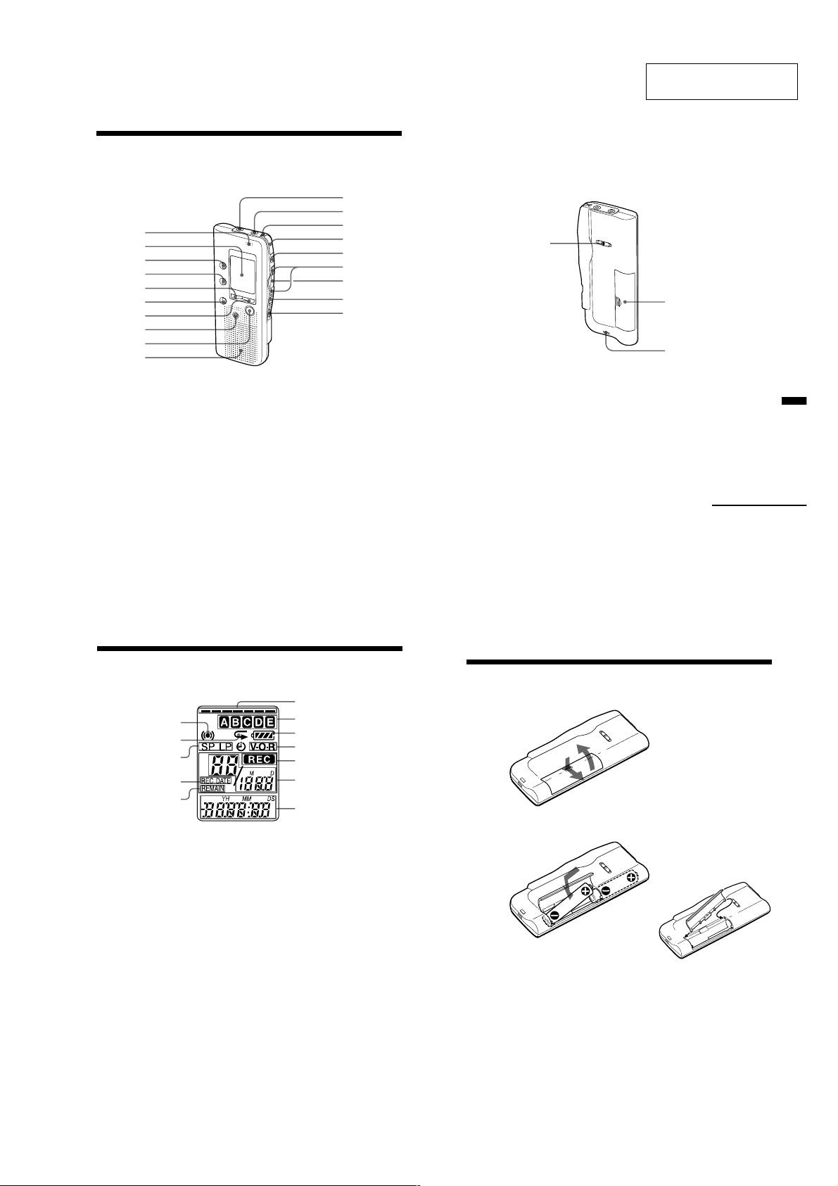
Index to Parts and Controls
Refer to the pages indicated in parentheses for details.
Main unit
1
2
3
4
5
6
7
8
9
q;
qa
qs
qd
qf
qg
qh
qj
qk
ql
SECTION 1
GENERAL
Rear
ICD-B10/B15
This section is extracted
from instruction manual.
w;
wa
ws
1 MIC (built-in microphone)
(10)
2 Display window (44)
3 FOLDER button (10, 14)
4 INDEX button (23)
5 DISPLAY button (34)
6 A-B REPEAT button (18)
7 MENU button (8, 27, 30, 35,
36)
8 ERASE button (19)
9 xSTOP button (11, 15)
q; Speaker
qa MIC (PLUG IN POWER)
jack (13)
qs EAR (ear phone) jack (15)
qd OPR (operation) indicator
(10, 15)
GB
42
qf zREC (record) /STOP
button (10, 21)
qg X PAUSE button (11, 15)
qh .REVIEW/ >CUE (fast
backward, review/fast
forward, cue•selection of
menu mode) button (8, 14,
16, 17, 23, 25, 27, 30, 35, 36)
qj NxPLAY/STOP
•EXECUTE (play/
stop•enter) button (8, 15, 16,
18, 26, 27, 30, 35, 36)
qk HOLD switch (33)
ql VOL (volume) control (15)
Index to Parts and Controls (continued)
Display window
1
2
3
4
5
1 Alarm indicator (32)
2 Repeat play indicator (16)
3
Recording mode indication (36)
4 REC DATE (recorded date)
indication (34)
5 REMAIN indicator (34)
6 Remaining memor y
indicator (12)
7
Folder indication (10, 14)
(For ICD-B10, folders D and
E do not appear.)
8
Remaining battery indicator (7)
9
VOR (voice operated
recording) indicator (13)
q;
REC (recording) indicator (10)
qa Selected message number
(10, 14)/Mode indication of
the menu (ON, OFF, etc.) (8,
20, 24, 27, 30, 35)
qs Counter /Remaining time
indication /Recording date
and time indication /
Current time indication
(15:30, etc.) (34)/Menu
indication /Messages
(ERASE, HOLD, etc.)
Note
The effect of the back light of the
display window may be reduced
in a bright location (ICD-B15 only).
6
7
8
9
q;
qa
qs
w; PLAY SPEED selector (16)
wa Batter y compartment (6)
ws
Hook for handstrap (not
supplied)
Continued
43
BGetting Started
Step 1: Installing the Batteries
1 Slide and lift the battery compartment lid.
2
1
2 Insert two LR03 (size AAA) alkaline batteries with correct
polarity, and close the lid.
2
2
1
If the battery compartment lid is
accidentally detached, attach it
as illustrated.
Clock setting display appears when you insert batteries for the first time,
or when you insert batteries after the unit has been without batteries for a
certain period of time. Please refer to Steps 2 to 4 in “Step 2: Setting the
Clock” on pages 8 and 9 to set the date and time.
Additional Information
GB
44
GB
GB
6
3
ICD-B10/B15
Replacing the batteries
The battery indicator on the display window shows the battery condition.
When
When
operation.
Battery life*
With continuous use, approx. 7.5 hours (SP)/15 hours (LP) of recording or
approx. 6 hours (SP)/8 hours (LP) of playback is possible.
* Using Sony alkaline batteries LR03 (SG)
* When playing back through the internal speaker with VOL control at around 4
The battery life may shorten depending on the operation of the unit.
Notes
• Do not use manganese batteries for this unit.
• When you replace the batteries, insert the new ones within 3 minutes after you
• When replacing the batteries, be sure to replace both batteries with new ones.
• Do not charge dry batteries.
• When you are not going to use the unit for a long time, remove the batteries to
Note on the “ACCESS” message
When you insert the batteries, “ACCESS” may appear on the display window.
Do not remove the batteries while this message is displayed.
If the unit is required to process excessive amount of data, “ACCESS” may be
displayed for an extended period of time. This is not a malfunction of the unit.
Wait until the message disappears before starting operation.
flashes, replace the batteries with new ones.
flashes, the batteries are exhausted and the unit will stop
removed the exhausted ones. Otherwise, the display may show the clock
setting display or incorrect date and time when you re-insert the batteries. In
this case, set the date and time again.
The recorded messages and alarm setting, however, will remain.
prevent damage from battery leakage and corrosion.
Getting
Started
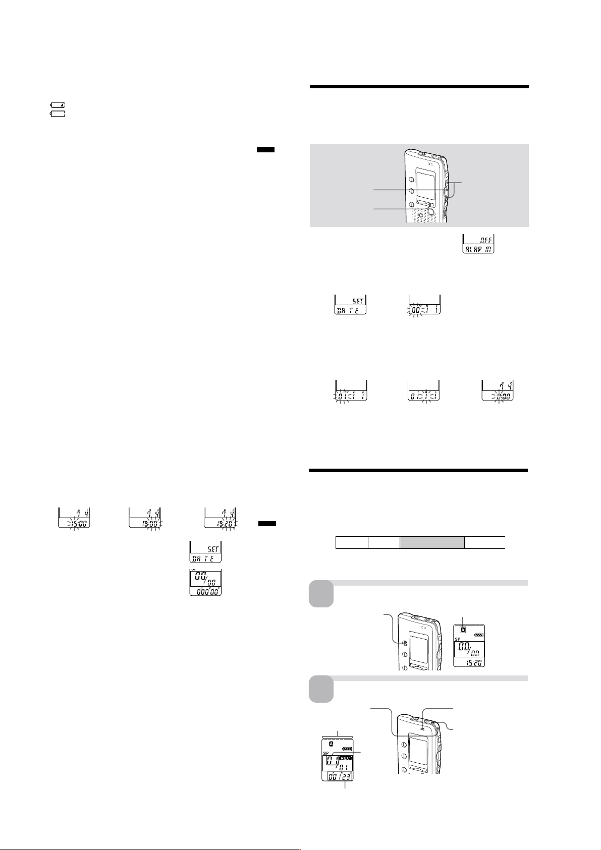
Step 2: Setting the Clock
You need to set the clock to use the alarm or timer setting function.
Clock setting display appears when you insert batteries for the first time,
or when you insert batteries after the unit has been without batteries for a
certain period of time. In this case, proceed from step 2.
NxPLAY/STOP
MENU
1
Press MENU to enter the menu mode.
2
Display the clock setting display.
1 Press .once to
display “SET
DATE”.
3
Set the date.
1 Press . or >
to select the
digits of the year.
2 Press NxPLAY/
STOP.
The year digits
will flash.
2 Press NxPLAY/
STOP.
The month digits
will flash.
./>
3 Set the month and
day in sequence,
then press
NxPLAY/STOP.
The hour digits will
flash.
4 Set the time.
1 Press . or >
to select the
digits of the hour.
5
Press NxPLAY/STOP at the time signal.
The display will return to “SET DATE”.
2 Press NxPLAY/
STOP.
The minute digits
will flash.
3 Set the minute.
6 Press MENU to exit the menu mode.
1 Tip
This unit does not have a power on/off switch. The display is shown at all
times.
GB
7
GB
8
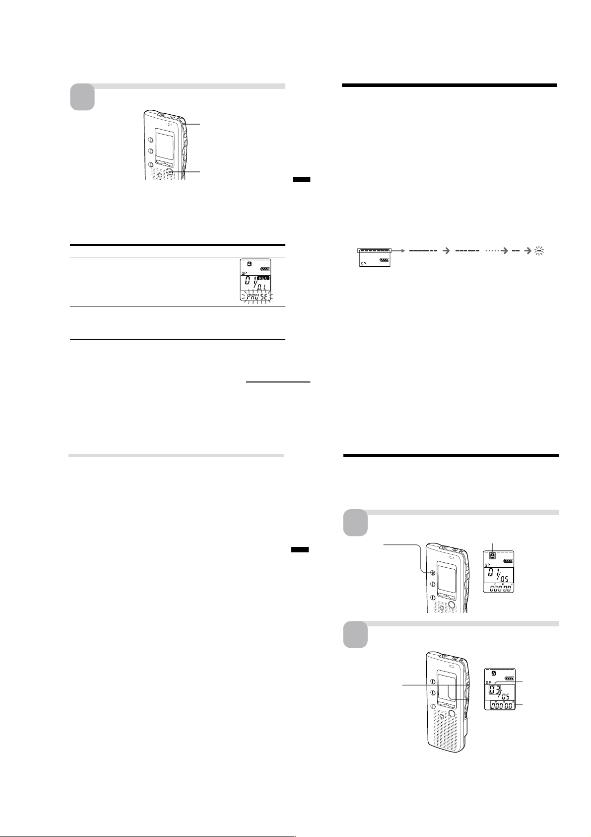
BBasic Operations
Recording Messages
You can record up to 99 messages in each of three folders (A, B, or C) for
ICD-B10 or five folders (A, B, C, D or E) for ICD-B15. Since a newly
recorded message is automatically added behind the last recorded
Getting Started
message, you can start recording quickly without searching for the end of
the last recording.
e.g. Message 1
Note
Before making a long recording, be sure to insert new batteries and check the
battery indicator (page 7).
1
Press FOLDER repeatedly
to display the folder in
which you wish to record
messages.
2
1 Press zREC/STOP.
Remaining memory
indicator
Message 2
Select the folder.
Start recording.
Current
message
number
Newly recorded message
Current folder
2 Speak to the built-in
OPR indicator
(lights in red during
recording.)
You do not need to keep
pressing zREC/STOP
while recording.
Blank space
microphone.
GB
9
Counter display*
GB
10
* The display selected with the DISPLAY button
(page 34) appears.
4
Stop recording.
3
Press zREC/STOP again.
The unit stops at the beginning
of the current recording.
xSTOP
If you do not change the folder after you stop recording, the next time you
record you will record in the same folder.
To stop recording
You can also stop recording by pressing xSTOP instead of zREC/STOP.
To pause recording
To Do this
pause recording* Press XPAUSE.
release pause and Press XPAUSE or zREC/STOP.
resume recording Recording resumes from that point.
released and the unit goes into the stop mode.
During recording pause,
the OPR indicator flashes
in red and “ PAUSE”
flashes in the display
window.
(To stop recording after pausing
recording, press xSTOP.)
pause recording, * 15 minutes after you recording pause is automatically
Basic Operations
ICD-B10/B15
Recording Messages (continued)
Recording Messages (continued)
To select the microphone sensitivity
See page 36.
Maximum recording time
With the ICD-B10, you can record for up to 63 minutes in SP (standard
play) mode and 168 minutes in LP (long play) mode. If you record
messages in a mixture of SP and LP modes, the recordable time varies
from 63 to 168 minutes.
With the ICD-B15, you can record for up to 127 minutes in SP (standard
play) mode and 339 minutes in LP (long play) mode. If you record
messages in a mixture of SP and LP modes, the recordable time varies
from 127 to 339 minutes.
The unit is factory-set to SP mode. To change the recording mode, see page 36.
You can check the remaining amount of recording time by selecting the
remaining recording time display mode. See page 34.
Remaining memory indication
During recording, the remaining memory indicator decreases one by one.
flashing
When the remaining time of recording reaches 5 minutes, the last one of
the indication flashes. When the remaining time of recording reaches 1
minute, the selected display mode (page 34) and “ REMAIN ” will flash one
after the other in the display window. When the memory is full, recording
automatically stops and “ FULL” will flash in the display window with an
alarm sound. To continue recording, first erase some of the messages (page
19).
Continued
11
Various Ways of Recording
Starting recording automatically in response to the sound
— Advanced VOR function
When the VOR (voice operated recording) function is set to ON (page 36),
recording starts when the recorder detects sound and stops when no
sound is heard.
Note
VOR function is affected by the sound around you. Set the microphone
sensitivity (SENS) to either HI (high) or LO (low) (see page 36). If recording is
not satisfactory after you have changed the microphone sensitivity, or for
important recording, set VOR to OFF.
Recording with an external microphone or from other
equipment
Connect a plug-in-power type microphone or other equipment to the MIC
(PLUG IN POWER) jack.
When you connect an external microphone, the built-in microphone is
automatically cut off. When a plug-in-power type microphone is
connected, power is automatically supplied to the microphone from the IC
recorder.
Adding a recording
To add a recording to a previously recorded message or to add an
overwrite recording during playback, see pages 21 and 22.
GB
Basic Operations
GB
12
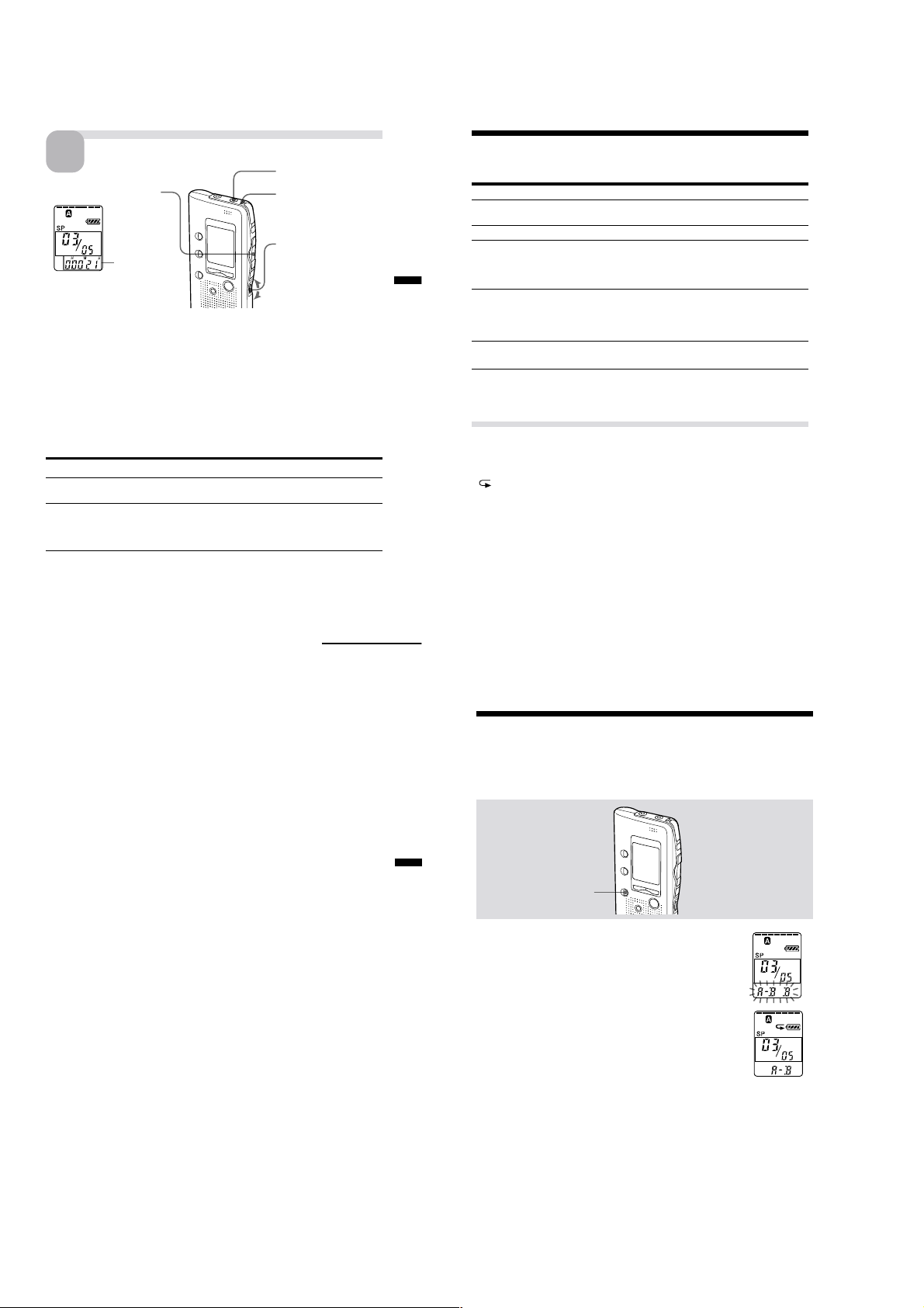
Playing Back Messages
Playing Back Messages
When playing back a previously recorded message, start from Step 1.
When playing back a message you have just finished recording, start from
Step 3.
Select the folder.
1
Press FOLDER
repeatedly to display
the folder you wish to
play back.
Select the message number.
2
Current folder
13
Press . or > to
display the desired
message number.
.: for smaller
message number
>: for larger
message number
* The display selected with the DISPLAY button (page 34) appears.
GB
14
GB
Selected
message
number
Counter
display*
5
ICD-B10/B15
Start playback.
3
1 Press NxPLAY/STOP.
Counter
display (or
the selected
display
mode)
After playing back one message, the unit stops at the beginning of the next
message.
When the last message on a folder has been played back, the unit stops at
the beginning of the last message.
For private listening
Connect an earphone or headphones (not supplied) to the EAR jack. The builtin speaker will be automatically disconnected. If you plug in headphones, you
will get monaural output from both left and right channels.
To stop playback
To Do this
stop at the beginning of Press xSTOP.
the current message
stop at the current position Press NxPLAY/STOP.
* You can also pause playback by pressing XPAUSE instead of NxPLAY/
STOP. The OPR indicator will flash in green. After an hour, the unit goes
into the stop mode at the current position.
Playing back all messages in a folder continuously
— Continuous Play
See page 36.
(Playback Pause function)*
To resume playback from that point,
press NxPLAY/STOP again.
EAR jack
OPR indicator
(lights in green
during playback.)
2 Turn VOL to adjust
the volume.
Continued
15
Playing Back Messages (continued)
Other operations
To Do this
go back to the beginning Press . once.***
of the current message**
skip to the next message** Press > once.***
go back to previous Press . or > repeatedly.***
messages/skip to (During stop mode, keep the button
Basic Operations
succeeding messages pressed to skip the messages
play back rapidly or Set PLAY SPEED to FAST or SLOW.
slowly The messages will be played back
play messages with Set PLAY SPEED to NORMAL.
normal speed
** If you have set a bookmark on the message, the unit stops at the bookmark.
*** These operations are for when EASY-S is set to OFF. For operations when
EASY-S is set to ON, see page 17.
continuously.)
about 30% faster or 15% slower than
normal.
Various Ways of Playback
Playing back a message repeatedly — Repeat Play
During playback, press NxPLAY/STOP for more than one second.
“
“ will be displayed and the selected message will be played back
repeatedly.
To resume normal playback, press NxPLAY/STOP again. To stop
playback, press xSTOP.
Playing the beginning of each message — Scanning Play
During stop mode, press NxPLAY/STOP for more than one second.
“SCAN” will be displayed in the display window and the first 5 seconds of
each message in the selected folder will be played back.
When you find the desired message, press NxPLAY/STOP. The message
will be played back until the end.
GB
16
GB
Searching forward/backward during playback (Cue/Review)
To search forward, keep > pressed during playback and release the
button at the point you wish to resume playback.
To search backward, keep . pressed during playback and release the
button at the point you wish to resume playback.
The unit searches at slow speed (unit of 4 seconds) with playback sound. It
is useful when checking one word forward or behind.
If you keep > or .pressed, the unit starts searching at higher speed.
Between messages the unit pauses for 2 seconds.
During cue/review, the counter will be displayed, regardless of the
display mode setting (page 34).
You can cue or review during playback pause. The unit goes back into
playback pause at the point you release > or ..
1 Tip
When fast playback is done to the end of the last message, “ END” flashes
for 5 seconds and the OPR indicator lights up in green. (You cannot hear
the playback sound.) If you keep . pressed while “ END” is flashing,
the messages are played back rapidly, and normal playback will start at
the point you release the button.
When “ END ” stops flashing and the OPR indicator goes off, the unit will
stop at the beginning of the last message.
If the last message is long and you wish to start playback at a later part of
the message, keep > pressed to play back the message to the end and
then press . while “ END” is flashing to go back to the desired point .
(For messages other than the last one, go to the beginning of the next
message and play backward to the desired point.)
Locating quickly the point you wish to start playback (Easy
Search)
When EASY-S is set to ON (page 36), you can quickly locate the point you
wish to start playback by pressing > or . repeatedly during playback
or playback pause.
You can go back approx. 3 seconds by pressing . once, or advance
approx 10 seconds by pressing > once. This function is useful when
locating a desired point in a long recording.
Basic Operations
Playing Back the Specified Section
Repeatedly — A-B Repeat
While playing back a message, you can set the start (A) and end (B) points
for a section you wish to play repeatedly.
A-B REPEAT
1 During playback, press A-B REPEAT briefly.
The starting point (A) of the section you wish to play
repeatedly is set. “A-B B” flashes.
2 During playback, press A-B REPEAT briefly.
The finishing point (B) of the section is set.
“ A-B” is displayed and the specified section is played
back repeatedly.
To resume normal playback
Press NxPLAY/STOP.
To stop A-B Repeat playback
Press xSTOP.
Notes
• You cannot set A-B Repeat for a section that overlaps two or more messages.
• If you do not set the finishing point (B), the finishing point is automatically set
at the end (or the beginning) of the message.
17
GB
18
GB
6
ICD-B10/B15
Erasing Messages
You can erase the recorded messages one by one or all messages in a folder
at a time.
Note that once a recording has been erased, you cannot retrieve it.
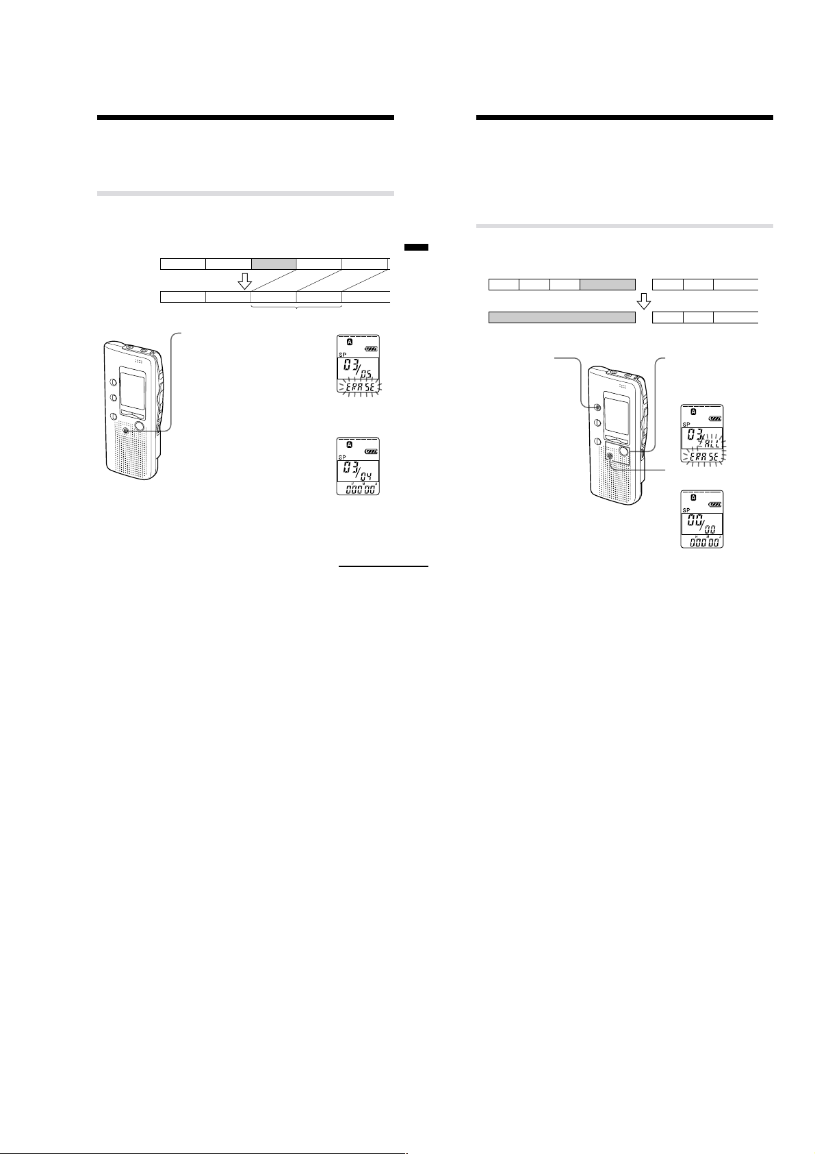
Erasing messages one by one
When a message is erased, the remaining messages will advance and
renumbered so that there will be no space between messages.
Before erasing
After erasing
Message 1
Erase Message 3
Message 1
1 Press ERASE while playing back
the message you want to erase
or press ERASE for more than 1
second during stop mode.
A beep will sound and the message
number and “ ERASE” will flash
while the first and last 5 seconds of
the message are played back 10
times.
2 Press ERASE while the message is
being played back.
The message is erased and the
remaining messages will be
renumbered. (For example, if you
erase Message 3, Message 4 will be
renumbered as Message 3. When
erasing is completed, the unit will
stop at the beginning of the
following message.)
To cancel erasing
Press xSTOP before step 2.
Message 3
Message 2 Message 3 Message 4
Remaining messages are renumbered.
Message 4 Message 5Message 2
Continued
GB
19
Basic Operations
Erasing Messages (continued)
To erase other messages
Repeat steps 1 and 2.
To erase a message partially
First divide the message by adding an index (see page 23) and then follow
the steps on page 19 to erase the message.
Erasing all messages in a folder
e.g.
Folder A
Message 1 Message 2 Message 3
Blank space
1 Press FOLDER to
select the folder you
want to erase.
To cancel erasing
Press xSTOP before step 3.
GB
20
Blank space
Folder B
Message 1 Message 2 Message 3
Message 1 Message 2 Message 3
2 While pressing xSTOP,
press ERASE for more
than 1 second.
“ ALL ERASE” will flash
for 10 seconds.
3 While the display is
flashing, press ERASE.
7
ICD-B10/B15
d
y
SECTION 2
DISASSEMBLY
Note : This set can be disassemble according to the following sequence.
Set Sub Block Assy, Upper Lid F-SW Board Main Board
Note : Follow the disassembly procedure in the numerical order given.
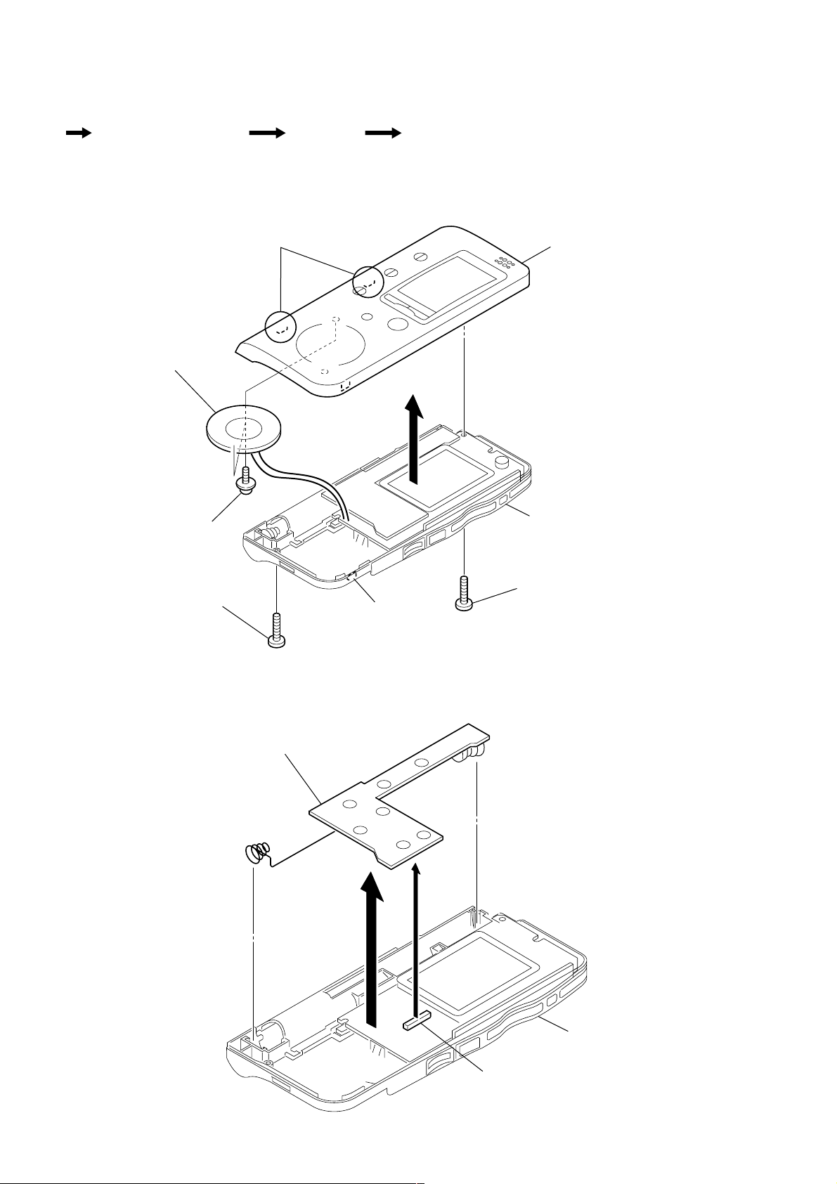
2-1. SUB BLOCK ASSY, UPPER LID
3
claws
8
speaker
5
6
sub block assy, upper li
7
screws (B1.7x2.5)
2-2. F-SW BOARD
screw (B1.7x7)
2
3
F-SW board
4
claw
case assy
1
screw (B1.7x10)
2
case ass
1
CN703
8
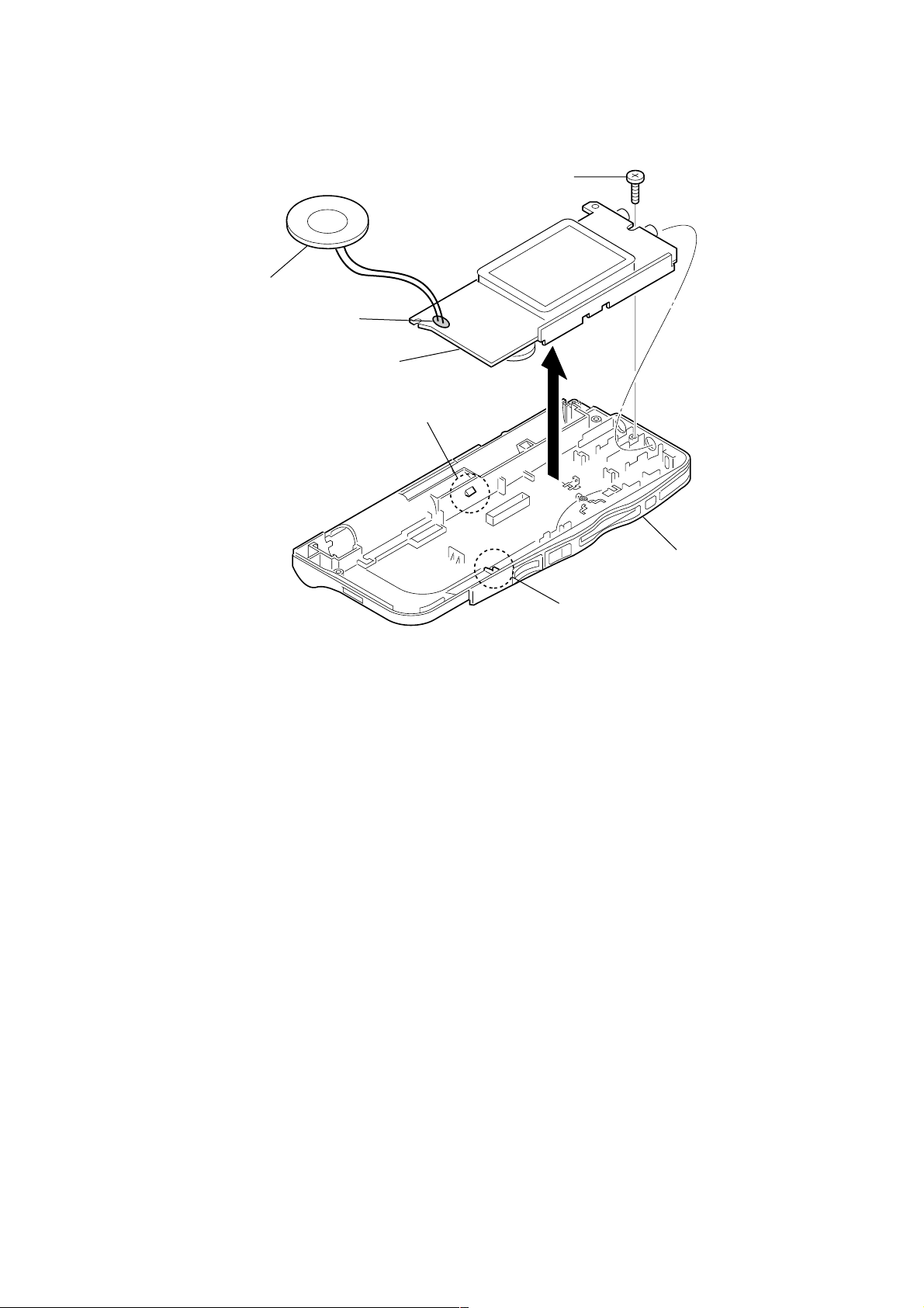
2-3. MAIN BOARD
y
2
speaker
1
Removal the solders
6
MAIN board
4
3
screw (B1.7x10)
claw
ICD-B10/B15
5
case ass
claw
9

ICD-B10/B15
SECTION 3
DIAGRAMS
3-1. IC PIN DESCRIPTIONS
• IC712 MB90523APFF-G-116-BND (SYSTEM CONTROL)
Pin No. Pin Name I/O Pin Description
1 RTCCE O Real-time clock chip enable signal output
2 BEEP O Beep signal output
3 XFLMRE O Flash memory read enable signal output
4 XFLMWE O Flash memory write enable signal output
5 FLMRB I Flash memory R/B signal input
6 DSPPWR O DSP power supply signal output
7 ADASYSCK O ADA codec system clock signal output
8 VCC — Power supply pin
9 DSPSYSCK O DSP system clock signal output
10 XZRST O Zephy reset signal output
11 DSPACK O DSP I/F acknowledge signal output
12 XDIFEN O DSP I/F enable signal output
13 DCOMDT O DSP I/F command/data signal output
14 SIN1 I DSP I/F serial data signal input
15 SOT1 O DSP I/F serial data signal output
16 SCK1 O DSP I/F serial clock signal output
17 – 32 SEG00 – 15 O LCD segment signal output
33 VSS — Ground pin
34 C — C (Connect to power supply pin.)
35 SIN2 I Zephyr/RTC I/F serial data signal input
36 SOT2 O Zephyr/RTC I/F serial data signal output
37 SCK2 O Zephyr/RTC I/F serial clock signal output
38 DVCC — Digital power supply pin
39 DVSS — Digital ground pin
40 ZIFACK O Zephyr I/F acknowledge signal output
41 SIPCS O Serial parallel converter IC I/F chip enable signal output
42 AVCC — Analog power supply pin
43 AVRH — A/D reference voltage H (Connect to VCC.)
44 AVRL — A/D reference voltage L (Connect to ground.)
45 AVSS — Analog ground pin
46 BATT I Battery level detection A/D signal input
47 KEYIN0 I Key A/D signal input 0
48 KEYIN1 I Key A/D signal input 1
49 SPEED I Speed switch A/D signal input
50 XVORSW I VOR switch signal input (Low: VOR switch ON)
51 HPJACK I Headphone jack ON/OFF signal input (Not used in this set.)
52 FLMSEL I Flash memory select A/D signal input
53 KEYPUP O Key pull-up signal output
54 VCC — Power supply pin
55 FLMALE O Flash memory address latch enable signal output (AND: OE)
56 FLMCLE O Flash memory command enable signal output (AND: CDE)
57 XVORIN I VOR signal input
58 XDSPRST O DSP reset signal output
59 – 62 COM0 – 3 O LCD common signal output
63 VSS — Ground pin
64 – 72 SEG16 – 24 O LCD segment signal output
73 SUBXTAL O Sub clock oscillation pin (Not used in this set.)
74 SUBCLK I Sub clock oscillation signal input (32.768 kHz)
10
 Loading...