

Page 1

4-578-367-12 (1)
2016-02
4K3D Video Recorder
Instructions for Use
Before operating the unit, please read this manual thoroughly
and retain it for future reference.
HVO-4000ST
© 2015 Sony Corporation
Page 2
Owner’s Record
The model and serial numbers are located at the rear.
Record these numbers in the space provided below.
Refer to these numbers whenever you call upon your
Sony dealer regarding this product.
Model No.
Serial No.
Indications for Use/Intended Use
The Sony HVO-4000ST 4K, 3D and 2D Video Recorder
is intended to record 4K video and still images from
endoscopic/laparoscopic camera systems, surgical
microscope and other compatible medical imaging
systems. This medical grade recorder can save video and
still images to an internal hard disk drive, a portable USB
drive, optical disk or to a compatible network server. The
recorded images can be used for the patient record,
training or education. The recorder is suitable for use in
hospital operating rooms, medical imaging centers,
surgical centers, clinics, doctor’s offices and similar
healthcare environments.
WARNING
If you don’t use the remote for an extended period of time,
remove the batteries to avoid possible damage from
battery leakage and corrosion.
Caution
Use of controls or adjustments or performance of
procedures other than those specified herein may result in
hazardous radiation exposure.
This HVO-4000ST is classified as a CLASS 1 LASER
PRODUCT. (IEC 60825-1: 2007)
Caution
The use of optical instruments with this product will
increase eye hazard.
WARNING
To reduce the risk of fire or electric shock, do not
expose this apparatus to rain or moisture.
To avoid electrical shock, do not open the
cabinet. Refer servicing to qualified personnel
only.
No modification of this equipment is allowed.
To avoid the risk of electric shock, this
equipment must only be connected to a supply
mains with protective earth.
WARNING
To disconnect the main power, unplug the power plug.
When installing the unit, incorporate a readily accessible
disconnect device in the fixed wiring, or connect the
power plug to an easily accessible socket-outlet near the
unit.
Do not position the ME equipment where it is difficult to
unplug the power plug.
If a fault should occur during operation of the unit,
operate the disconnect device to switch the power supply
off, or unplug the power plug.
CAUTION
The apparatus shall not be exposed to dripping or
splashing. No objects filled with liquids, such as vases,
shall be placed on the apparatus.
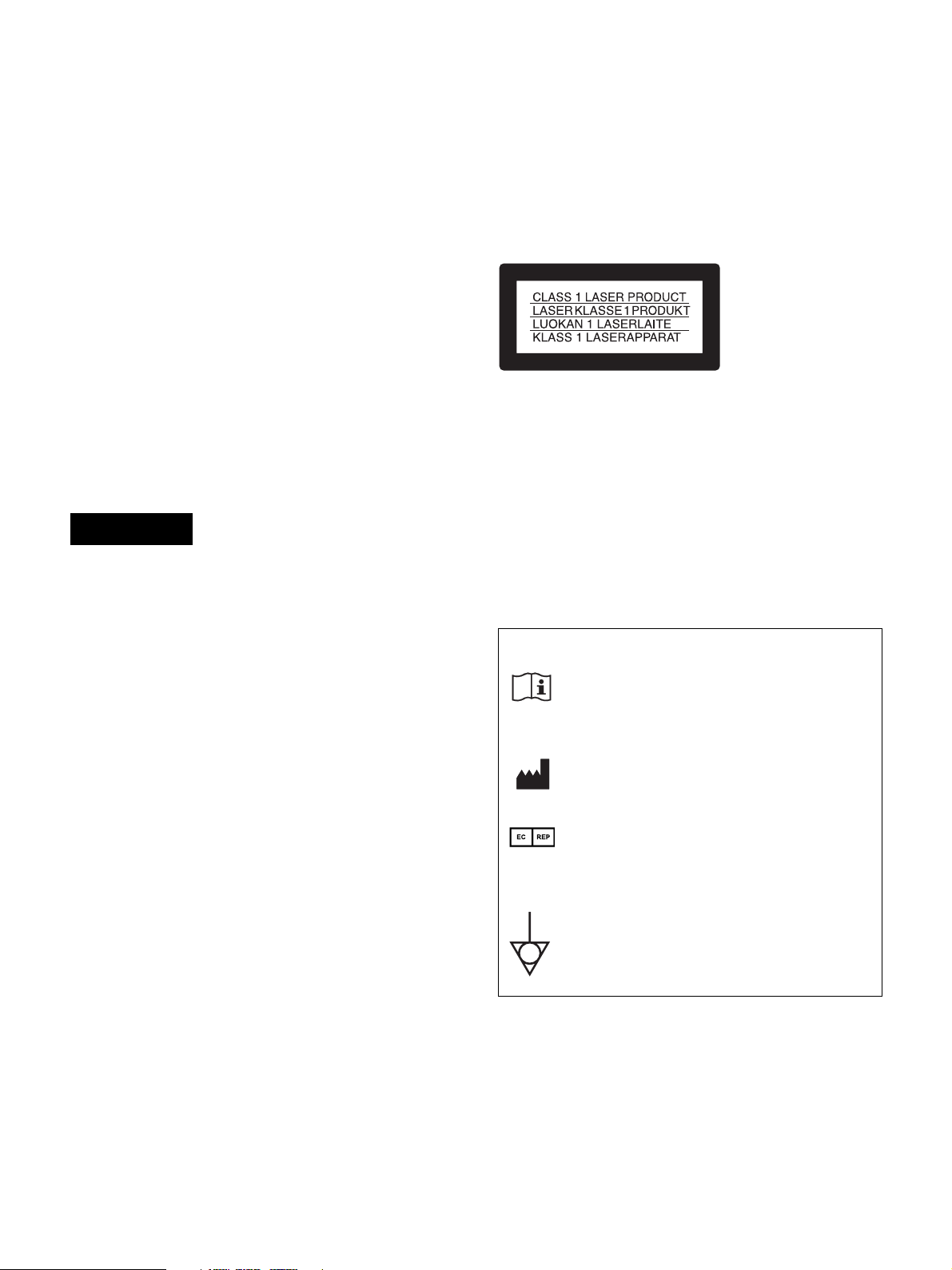
Symbols on the products
Consult the Instructions for Use
Follow the directions in the Instructions for
Use for parts of the unit on which this mark
appears.
This symbol indicates the manufacturer, and
appears next to the manufacturer’s name and
address.
This symbol indicates the European
Community representative, and appears next
to the European Community representative’s
name and address.
This symbol indicates the equipotential
terminal which brings the various parts of a
system to the same potential.
CAUTION
Danger of explosion if battery is incorrectly replaced.
Replace only with the same or equivalent type
recommended by the manufacturer.
When you dispose of the battery, you must obey the law
in the relative area or country.
2
Page 3
For the customers in the U.S.A.
This equipment has been tested and found to comply with
the limits for a Class A digital device, pursuant to part 15
of the FCC Rules. These limits are designed to provide
reasonable protection against harmful interference when
the equipment is operated in a commercial environment.
This equipment generates, uses, and can radiate radio
frequency energy and, if not installed and used in
accordance with the instruction manual, may cause
harmful interference to radio communications. Operation
of this equipment in a residential area is likely to cause
harmful interference in which case the user will be
required to correct the interference at his own expense.
You are cautioned that any changes or modifications not
expressly approved in this manual could void your
authority to operate this equipment.
All interface cables used to connect peripherals must be
shielded in order to comply with the limits for a digital
device pursuant to Subpart B of part 15 of FCC Rules.
This device complies with part 15 of the FCC Rules.
Operation is subject to the following two conditions: (1)
This device may not cause harmful interference, and (2)
this device must accept any interference received,
including interference that may cause undesired
operation.
4. For this particular equipment, all accessory equipment
connected as noted above, must be connected to mains
via an additional isolation transformer conforming
with the construction requirements of IEC 60601-1
and providing at least Basic Insulation.
5. This equipment generates, uses, and can radiate radio
frequency energy. If it is not installed and used in
accordance with the instruction manual, it may cause
interference to other equipment. If this unit causes
interference (which can be determined by unplugging
the power cord from the unit), try these measures:
Relocate the unit with respect to the susceptible
equipment. Plug this unit and the susceptible
equipment into different branch circuit.
Consult your dealer. (According to standard IEC 606011-2 and CISPR11, Class B, Group 1)
Caution
Federal law (United States of America) restricts this
device to sale by or on the order of a licensed healthcare
practitioner.
For the customers in Canada
CAN ICES-3 (A)/NMB-3(A)
This unit has been certified according to Standard CAN/
CSA-C22.2 No.60601-1.
Important safeguards/notices for use in
the medical environments
1. All the equipments connected to this unit shall be
certified according to Standard IEC 60601-1,
IEC 60950-1, IEC 60065 or other IEC/ISO Standards
applicable to the equipments.
2. Furthermore all configurations shall comply with the
system standard IEC 60601-1. Everybody who
connects additional equipment to the signal input part
or signal output part configures a medical system, and
is therefore, responsible that the system complies with
the requirements of the system standard IEC 60601-1.
If in doubt, consult the qualified service personnel.
3. The leakage current could increase when connected to
other equipment.
3
Page 4

Important EMC notices for use in the medical environments
• The HVO-4000ST needs special precautions regarding EMC and needs to be installed and put into service according to
the EMC information provided in the instructions for use.
• The portable and mobile RF communications equipment such as cellular phones can affect the HVO-4000ST.
Warning
The use of accessories and cables other than those specified, with the exception of replacement parts sold by Sony
Corporation, may result in increased emissions or decreased immunity of the HVO-4000ST.
Guidance and manufacturer’s declaration-electromagnetic emissions
The HVO-4000ST is intended for use in the electromagnetic environment specified below.
The customer or the user of the HVO-4000ST should assure that it is used in such an environment.
Emission test Compliance Electromagnetic environment-guidance
RF emissions
CISPR 11
RF emissions
CISPR 11
Harmonic
emissions
Group 1
Class B
Class A
The HVO-4000ST uses RF energy only for its internal
function. Therefore, its RF emissions are very low
and are not likely to cause any interference in nearby
electronic equipment.
The HVO-4000ST is suitable for use in all
establishments, including domestic establishments
and those directly connected to the public lowvoltage power supply network that supplies buildings
used for domestic purposes.
IEC 61000-3-2
Voltage
fluctuations/flicker
emissions
IEC 61000-3-3
Warning
If the HVO-4000ST should be used adjacent to or stacked with other equipment, it should be observed to verify normal
operation in the configuration in which it will be used.
Complies
4
Page 5

Guidance and manufacturer’s declaration - electromagnetic immunity
The HVO-4000ST is intended for use in the electromagnetic environment specified below. The customer or
the user of the HVO-4000ST should assure that it is used in such as environment.
Immunity test
Electrostatic
discharge (ESD)
IEC 60601
test level
±6 kV contact
Compliance
level
±6 kV contact
Electromagnetic environment-guidance
Floors should be wood, concrete or ceramic tile. If
floors are covered with synthetic material, the relative
humidity should be at least 30%.
IEC 61000-4-2
Electrical fast
transient/burst
±8 kV air
±2 kV for power
supply lines
±8 kV air
±2 kV for power
supply lines
Mains power quality should be that of a typical
commercial or hospital environment.
IEC 61000-4-4
Surge
IEC 61000-4-5
Voltage dips,
short
interruptions and
voltage
variations on
power supply
input lines
IEC 61000-4-11
Power frequency
(50/60 Hz)
magnetic field
±1 kV for input/
output lines
±1 kV line(s) to
line(s)
±2 kV line(s) to
earth
< 5% U
T
(> 95% dip in
)
U
T
for 0.5 cycle
40% U
T
(60% dip in U
for 5 cycles
70% U
T
(30% dip in U
for 25 cycles
< 5% U
T
(> 95% dip in
U
)
T
for 5 sec
±1 kV for input/
output lines
±1 kV differential
mode
±2 kV common
mode
< 5% U
(> 95% dip in
)
U
T
for 0.5 cycle
40% U
)
(60% dip in UT)
T
for 5 cycles
70% U
)
(30% dip in UT)
T
for 25 cycles
< 5% U
(> 95% dip in
U
)
T
for 5 sec
Mains power quality should be that of a typical
commercial or hospital environment.
T
Mains power quality should be that of a typical
commercial or hospital environment. If the user of the
HVO-4000ST requires continued operation during
power mains interruptions, it is recommended that
the HVO-4000ST be powered from an uninterruptible
T
T
T
power supply or a battery.
3 A/m 3 A/m Power frequency magnetic fields should be at levels
characteristic of a typical location in a typical
commercial or hospital environment.
IEC 61000-4-8
NOTE: U
is the a.c. mains voltage prior to application of the test level.
T
5
Page 6
Guidance and manufacturer’s declaration - electromagnetic immunity
The HVO-4000ST is intended for use in the electromagnetic environment specified below. The customer or
the user of the HVO-4000ST should assure that it is used in such as environment.
Immunity test
IEC 60601
test level
Compliance
level
Electromagnetic environment-guidance
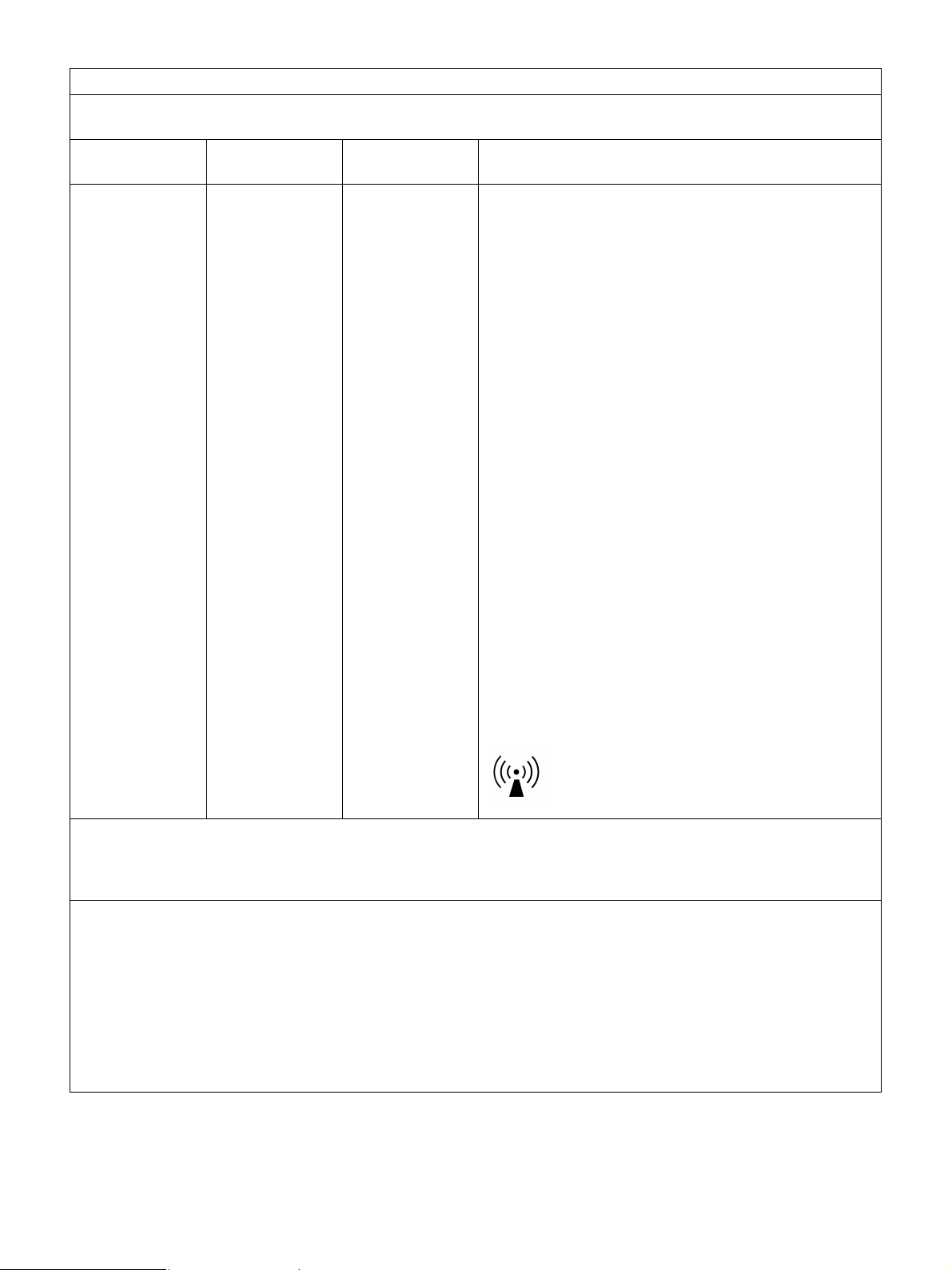
Portable and mobile RF communications equipment
should be used no closer to any part of the HVO4000ST, including cables, than the recommended
separation distance calculated from the equation
appliance to the frequency of the transmitter.
Recommended separation distance
Conducted RF
IEC 61000-4-6
Radiated RF
IEC 61000-4-3
3 Vrms
150 kHz to
80 MHz
3 V/m
80 MHz to
2.5 GHz
3 Vrms
3 V/m
d = 1.2 √P
d = 1.2 √P 80 MHz to 800 MHz
d = 2.3 √P 800 MHz to 2.5 GHz
Where P is the maximum output power rating of the
transmitter in watts (W) according to the transmitter
manufacturer and d is the recommended separation
distance in meters (m).
Field strengths from fixed RF transmitters, as
determined by an electromagnetic site survey,
a
should be less than the compliance level in each
frequency range.
b
Interference may occur in the vicinity of equipment
marked with following symbol:
NOTE 1: At 80 MHz and 800 MHz, the higher frequency range applies.
NOTE 2: These guidelines may not apply in all situations. Electromagnetic propagation is affected by
absorption and reflection from structures, objects and people.
a Field strengths from fixed transmitters, such as base stations for radio (cellular/cordless) telephones and
land mobile radios, amateur radio, AM and FM radio broadcast and TV broadcast cannot be predicted
theoretically with accuracy.
To assess the electromagnetic environment due to fixed RF transmitters, an electromagnetic site survey
should be considered. If the measured field strength in the location in which the HVO-4000ST is used
exceeds the applicable RF compliance level above, the HVO-4000ST should be observed to verify normal
operation. If abnormal performance is observed, additional measures may be necessary, such as
reorienting or relocating the HVO-4000ST.
b Over the frequency range 150 kHz to 80 MHz, field strengths should be less than 3 V/m.
6
Page 7
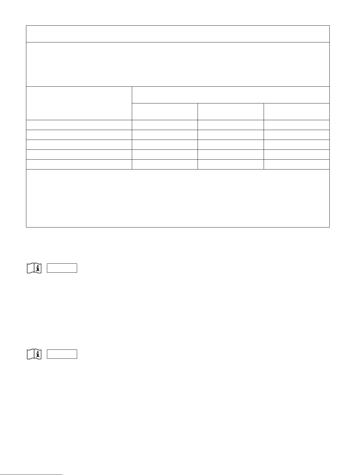
Recommended separation distances between portable and mobile RF communications equipment and
the HVO-4000ST
The HVO-4000ST is intended for use in an electromagnetic environment in which radiated RF disturbances
are controlled.
The customer or the user of the HVO-4000ST can help prevent electromagnetic interference by maintaining
a minimum distance between portable and mobile RF communications equipment (transmitters) and the
HVO-4000ST as recommended below, according to the maximum output power of the communications
equipment.
Rated maximum output power of
transmitter
W
Separation distance according to frequency of transmitter
m
150 kHz to 80 MHz
d = 1.2 √P
80 MHz to 800 MHz
d = 1.2 √P
800 MHz to 2.5 GHz
d = 2.3 √P
0.01 0.12 0.12 0.23
0.1 0.380.380.73
1 1.2 1.2 2.3
10 3.8 3.8 7.3
100 12 12 23
For transmitters rated a maximum output power not listed above, the recommended separation distance d in
meters (m) can be estimated using the equation applicable to the frequency of the transmitter, where P is the
maximum output power rating of the transmitter in watts (W) according to the transmitter manufacturer.
NOTE 1: At 80 MHz and 800 MHz, the separation distance for the higher frequency range applies.
NOTE 2: These guidelines may not apply in all situations. Electromagnetic propagation is affected by
absorption and reflection from structures, objects and people.
CAUTION
When you dispose of the unit or accessories, you must obey the laws in the relative area or country and the regulations in
the relative hospital regarding environmental pollution.
WARNING
Using this unit for medical purposes
The connectors on this unit are not isolated.
Always use USB-compatible external hard drives and USB memory devices that operate solely on the power supplied by
the unit.
Connecting a device that operates on an AC power supply may result in an influx of leakage currents from the connected
device, which may in turn result in electric shocks to the patient and operator.
If use of such devices cannot be avoided, be sure to connect an isolation transformer to the power supply of the connected
device or connect an isolator between the connection cables to isolate the power supply, and verify that the risk of electric
shock from the system has been sufficiently reduced to levels that conform to IEC 60601-1 standards.
WARNING
Using this unit for medical purposes
This equipment’s connectors are not isolated.
Do not connect any device other than one which conforms to IEC 60601-1.
When an information technology device or AV device that uses an alternating current is connected, current leakage may
result in an electric shock to the patient or operator.
If use of such a device is unavoidable, isolate its power supply by connecting an isolation transformer, or by connecting
an isolator between the connecting cables.
After implementing these measures, confirm that the reduced risk now conforms to IEC 60601-1.
7
Page 8
WARNING on power connection
Use a proper power cord for your local power supply.
1. Use the approved Power Cord (3-core mains lead) / Appliance Connector / Plug with earthing-contacts that conforms
to the safety regulations of each country if applicable.
2. Use the Power Cord (3-core mains lead) / Appliance Connector / Plug conforming to the proper ratings (Voltage,
Ampere). If you have questions on the use of the above Power Cord / Appliance Connector / Plug, please consult a
qualified service personnel.
WARNING on power connection for medical use
Please use the following power supply cord. With connectors (plug or female) and cord types other than those indicated in
this table, use the power supply cord that is approved for use in your area.
United States and Canada
Plug Type HOSPITAL GRADE
*
Cord Type Min. Type SJT
Min. 18 AWG
Minimum Rating for Plug and
10A/125V
Appliance Couplers
Safety Approval UL Listed and CSA
* Note: Grounding reliability can only be achieved when the equipment is connected to an equivalent receptacle marked
‘Hospital Only’ or ‘Hospital Grade’.
CAUTION Network connector (RJ-45)
For safety, do not connect the connector for peripheral device wiring that might have excessive voltage to this port. Follow
the instructions for this port.
WARNING
Batteries shall not be exposed to excessive heat such as sunshine, fire or the like.
Caution
Do not come into contact with the terminals of the rear panel connectors and patients at the same time.
Doing so may result in a generation of voltage that can be harmful to patients if the unit is malfunctioning.
Always disconnect the power cord before connecting and disconnecting connectors.
Caution
Do not come into contact with the unit’s internal circuits and patients at the same time.
Doing so may result in a generation of voltage that can be harmful to patients if the unit is malfunctioning.
Note
To prevent the interior of the unit from overheating, keep the rear of the unit completely clear, and maintain a clearance of
at least 10 cm (4 in.) around the rest of the unit.
WAR N ING
Excessive sound pressure from earphones and headphones can cause hearing loss.
In order to use this product safely, avoid prolonged listening at excessive sound pressure levels.
8
Page 9
For the State of California, USA only
Perchlorate Material - special handling may apply, See
www.dtsc.ca.gov/hazardouswaste/perchlorate
For the customers in the U.S.A.
SONY LIMITED WARRANTY
http://www.sony.com/psa/warranty
warranty applicable to this product.
For the customers in Canada
SONY LIMITED WARRANTY
http://www.sonybiz.ca/pro/lang/en/ca/article/resources-warranty-product-registration
complete terms and conditions of Sony’s limited warranty applicable to this product.
For the customers in Europe
Sony Professional Solutions Europe - Standard Warranty and Exceptions on Standard Warranty.
Please visit http://www.pro.sony.eu/warranty
For the customers in Korea
SONY LIMITED WARRANTY
http://bpeng.sony.co.kr/handler/BPAS-Start
limited warranty applicable to this product.
- Please visit
for important information and complete terms and conditions of Sony’s limited
- Please visit
for important information and
for important information and complete terms and conditions.
- Please visit
for important information and complete terms and conditions of Sony’s
9
Page 10

Table of Contents
Please Read First ....................................13
Usage Notes.............................................15
Chapter 1 Overview
Features ...................................................16
System Configuration Example .............17
Names and Functions of Parts...............18
Front ............................................................ 18
Rear.............................................................. 20
Infrared Remote Control Unit
(RM-M010) .................................................22
Status Displays ............................................24
Setting Screens ............................................25
Using the On-Screen Keyboard
(Text Entry) ..............................................26
Names and Functions of Parts (On-Screen
Keyboard) .................................................... 26
Handling Discs ........................................27
Notes on Handling....................................... 27
Inserting and Removing Discs..................... 28
Chapter 2 Preparation
Connections.............................................29
Turning the Unit On and Off...................29
Configuring System Settings.................30
Configuring Recording Settings
(User Settings).........................................31
Displaying the [User Settings] Screen......... 31
Configuring Input Signal Settings ............... 31
Configuring Image Quality Settings............ 31
Configuring Recording Settings .................. 32
Configuring Save Settings........................... 32
Configuring Print Settings........................... 33
Configuring Other Settings.......................... 34
Function Keys..........................................35
Using Function Keys ................................... 35
Factory Assigned Functions ........................ 35
Other Assignable Functions ........................ 36
4K Convert Modes ..................................37
Chapter 3 Basic Recorder
Operations
Operation Flow........................................ 39
Step 1: Record.........................................40
Step 2: Capture Still Images ..................41
Step 3: Quick Playback .......................... 41
Step 4: End Recording ...........................42
Chapter 4 Recording and Playback
Recording Preparation ...........................43
Patient Information and Data Storage
Settings........................................................ 43
Using a Hard Keyboard for Patient
Information and Data Storage Settings ....... 44
Registering Multiple Patients in
Advance....................................................... 44
Test Recording ............................................ 45
Recording ................................................ 46
Manual Recording....................................... 46
Capture Still Images ............................... 47
Manual Still Image Capture ........................ 47
Using the Ch1/Ch2 Simultaneous
Recording Function ................................48
Configuring Settings for Ch1/Ch2
Simultaneous Recording ............................. 48
Performing Ch1/Ch2 Simultaneous
Recording .................................................... 48
Playback ..................................................48
Playing Back the Most Recent Data (Quick
Playback)..................................................... 48
Image Search...........................................49
Specifying Search Conditions..................... 49
Viewing Thumbnails of Recorded Data...... 49
Playback from the Search Results List........ 50
Sorting the Recorded Data List ................... 50
Processing Recorded Data ....................51
Printing........................................................ 51
Copying to External Media ......................... 52
10
Page 11

Editing Patient Information ......................... 53
Protecting Recorded Data............................ 54
Deleting Recorded Data .............................. 54
Viewing Information on Recorded Data ..... 54
Chapter 5 System Administrator
Settings
Displaying the [System Admin Settings]
Screen ......................................................56
Language and Time Settings .................57
List of time zones ........................................57
Function Settings ....................................59
[Patient Info.] Tab ....................................... 59
[Input Detection] Tab .................................. 59
[Input Signal] Tab........................................ 59
[Auto Live] Tab........................................... 59
[General 1] Tab............................................ 60
[General 2] Tab............................................ 61
[Facility] Tab ............................................... 61
[CMS] Tab................................................... 61
Device Settings........................................62
[Device 1] Tab ............................................. 62
[Device 2] Tab ............................................. 64
[Control] Tab ............................................... 64
[Contact Switch] Tab................................... 65
Password Settings ..................................66
Network Settings.....................................67
[Network] Tab .............................................67
[IP Address] Tab.......................................... 67
[DNS Server] Tab........................................ 68
[File Server] Tab.......................................... 68
[Shared] Tab ................................................ 68
[NTP] Tab.................................................... 68
Doctor List Registration .........................69
Registering Doctors ..................................... 69
[General] Tab............................................... 69
[File Server] Tab.......................................... 69
[Shared] Tab ................................................ 69
[Print] Tab ................................................... 69
[External Media] Tab .................................. 70
Editing the Doctor List............................70
Sorting the Doctor List................................ 70
Editing Doctor Settings............................... 70
Deleting Doctors ......................................... 71
Editing Cases ..........................................71
Registering Cases ........................................ 71
Deleting Cases............................................. 71
Sorting the Case List ................................... 72
Editing Case Names .................................... 72
Selecting Categories.................................... 72
Editing Categories....................................... 72
Sorting the Category List ............................ 72
Editing Category Names ............................. 72
Auto Delete Settings...............................73
DICOM Settings....................................... 73
[Server] Tab ................................................ 73
[Local Station 1] Tab .................................. 73
[Local Station 2] Tab .................................. 74
Chapter 6 Touch Panel and Mouse
Overview..................................................75
Configuring Touch Panel / Mouse
Settings....................................................75
Screen Displays in Touch Panel /
Mouse Mode ............................................ 76
[MENU] Screen .......................................... 76
[Status] Screen ............................................ 77
Video Playback Screen ............................... 77
Still Image Playback Screen........................ 78
Chapter 7 Miscellaneous
Error Messages.......................................79
Troubleshooting...................................... 81
Licenses...................................................82
DCMTK ...................................................... 82
libjpeg.......................................................... 82
LibTIFF ....................................................... 82
zlib............................................................... 82
GNU GPL/LGPL Licensed Software.......... 82
GNU GENERAL PUBLIC LICENSE ........82
11
Page 12

Preamble ...................................................... 82
TERMS AND CONDITIONS FOR
COPYING, DISTRIBUTION AND
MODIFICATION........................................ 83
END OF TERMS AND CONDITIONS.......86
How to Apply These Terms to Your New
Programs...................................................... 86
GNU LESSER GENERAL PUBLIC
LICENSE...................................................87
Preamble ...................................................... 87
TERMS AND CONDITIONS FOR
COPYING, DISTRIBUTION AND
MODIFICATION........................................ 88
END OF TERMS AND CONDITIONS.......92
How to Apply These Terms to Your New
Libraries....................................................... 92
Specifications..........................................93
Index ........................................................95
Trademarks
• Blu-ray Disc™, Blu-ray™, and their logos are trademarks of Blu-ray Disc Association.
• The terms HDMI and HDMI High-Definition Multimedia Interface, and the HDMI Logo are trademarks or registered
trademarks of HDMI Licensing LLC in the United States and other countries.
• “Innovation by Sony & Olympus” Phrase and indicate the mark of advanced medical imaging solution from
Sony and Olympus.
• The products or system names appearing in this document are trademarks or registered trademarks of their respective
owners.
Further, the ® or ™ symbols are not used in the text.
• Reproduction or duplication, in whole or part, of the software or operation manual supplied with the recorder, as well
as renting or leasing of the software without the authorization of the right holder is prohibited under copyright law.
• Sony assumes no responsibility for damages, loss of income, or any claims from a third party arising out of use of
the recorder or supplied software.
• For complete terms and conditions of the warranty for the recorder, refer to the warranty card included in the
package.
• The software supplied with the recorder cannot be used with any other recorders.
• It is not possible to install any software into the equipment other than the software supplied by Sony specifically for
use with the equipment.
• Note that the specifications of the recorder and supplied software are subject to change for improvement without
prior notice.
12
Page 13

Please Read First
Copyright
Using this unit for video and/or audio recording, or
distribution over the network or otherwise may in some
cases require the permission of the copyright holder of the
video or audio. To protect copyright, observe the
following points carefully when using this unit.
• When connecting a recording device to this and
recording video or audio, carefully observe laws
relating to copyright.
• Without the permission of the copyright holder, the
showing or distribution of video or audio material of
which the copyright is held by a third party, or the act
of recording on the hard disk of this unit, sharing
folders, and permitting of access to a private group or to
the public is prohibited by law.
• With a software upgrade or functional extension, with
the object of protecting copyright, the specifications for
the video and audio signals that can be input may be
changed without notice.
• Under copyright law, you may not use recorded video
or audio other than for your personal enjoyment without
the permission of the copyright holder. Note that at live
performances, shows and exhibitions, even for your
personal entertainment shooting may be restricted.
Disclaimer of Liability for Recorded Data
Sony Corporation does not accept any liability
whatsoever for any problems arising from a failure to
record, or from damage or erasure of recorded content on
this equipment, for any reason. This includes claims for
compensation of recorded content, and for any
concomitant and consequential damages. Sony
Corporation will not repair, restore, or duplicate any
recorded content. Your use of this product is subject to
these conditions.
Problems may occur if you perform the following
operations:
• When you use a disc recorded using this unit with
another BD (Blu-ray Disc)/DVD recorder or the BD/
DVD drive of a personal computer. Discs recorded
using this unit will not play back on other BD/DVD
recorders.
• When you attempt to re-use a disc with this unit, after
using it in the operations described above.
• When you use a disc recorded using another BD/DVD
recorder or BD/DVD drive of a personal computer with
this unit. Discs recorded using other BD/DVD
recorders or computers will not play back on this unit.
Deletion of data when disposing of the
unit
Before disposing of the unit, you first must delete patient
data and other confidential information that is stored
therein.
Failure to delete stored data before disposing of the unit
could expose confidential information to third parties. If
you have any questions in this regard, contact your Sony
dealer.
On security
SONY WILL NOT BE LIABLE FOR DAMAGES OF
ANY KIND RESULTING FROM A FAILURE TO
IMPLEMENT PROPER SECURITY MEASURES ON
TRANSMISSION DEVICES, UNAVOIDABLE DATA
LEAKS RESULTING FROM TRANSMISSION
SPECIFICATIONS, OR SECURITY PROBLEMS OF
ANY KIND.
Depending on the operating environment, unauthorized
third parties on the network may be able to access the unit.
When connecting the unit to the network, be sure to
confirm that the network is protected securely.
On condensation
If the unit is suddenly taken from a cold to a warm
location, or if ambient temperature suddenly rises,
moisture may form on the outer surface of the unit and/or
inside of the unit. This is known as condensation. If
condensation occurs, turn off the unit and wait until the
condensation clears before operating the unit. Operating
the unit while condensation is present may damage the
unit.
LCD panel
The LCD panel fitted to this unit is manufactured with
high precision technology, giving a functioning pixel
ratio of at least 99.99%. Thus a very small proportion of
pixels may be “stuck”, either always off (black), always
on (red, green, or blue), or flashing. In addition, over a
long period of use, because of the physical characteristics
of the liquid crystal display, such “stuck” pixels may
appear spontaneously. These problems are not a
malfunction. Note that any such problems have no effect
on recorded data.
LCD image display
Due the physical characteristics of LCD panels, there may
be a decrease in brightness or change in color temperature
over a long period of use. These problems are not a
malfunction.
In addition, these occurrences will not affect recorded
data.
13
Page 14

On consumable parts
• The HDD, fan, battery, and BD/DVD drive are
consumable parts that will need periodic replacement.
When operating at room temperature, a normal
replacement cycle will be about 2 to 3 years.
However, this replacement cycle represents only a
general guideline and does not imply that the life
expectancy of these parts is guaranteed. For details on
parts replacement, contact your dealer.
• The life expectancy of the electrolytic capacitor is about
5 years under normal operating temperatures and
normal usage (8 hours per day; 25 days per month). If
usage exceeds the above normal usage frequency, the
life expectancy may be reduced correspondingly.
When HDD seems to be faulty
Even if the HDD is showing signs of malfunction, be sure
to observe all the above precautions. This will prevent
further damage from occurring until the problem can be
diagnosed and corrected.
Replacement of the HDD and other consumable
parts
The HDD and battery are consumable parts that will need
periodic replacement. When operating at room
temperature, a normal replacement cycle will be about
two to three years. However, this replacement cycle
represents only a general guideline and does not imply
that the life expectancy of these parts is guaranteed. For
details on parts replacement, contact your dealer.
Precautions for products with built-in
HDD
This unit has a built-in hard disk drive (HDD). The HDD
is a precision device. If subject to shock, vibration, static
electricity, high temperature or humidity, data loss can
occur. When installing and using the unit, closely observe
the following precautions.
Protect from shocks and vibrations
When subject to shocks or vibrations, the HDD can be
damaged and loss of data on the HDD can occur.
• When transporting the unit, use the specified packing
material. When transporting on a dolly or similar, use a
type which does not transmit excessive vibrations.
Excessive shocks and vibrations can damage the HDD.
• Never move the unit while it is powered.
• Do not remove panels or outer parts of the unit.
• When placing the unit on a floor or other surface, make
sure that the unit is equipped with the specified rubber
feet, and put the unit down carefully. If there are no feet,
mount the rubber feet first.
• Do not place the unit near other devices that may
become a source of vibrations.
Wait for 30 seconds after turning power off
For a brief interval after the power is turned off, the
platters inside the HDD will still keep spinning and the
heads will be in an insecure position. During this interval,
the unit is more susceptible to shocks and vibrations than
during normal operation. For a period of at least 30
seconds after turning power off, avoid subjecting the unit
even to very light shocks. After this period, the hard disk
will be fully stopped and the unit can be manipulated.
Notes on media
Operation with all optical media or USB media is not
guaranteed. Contact your dealer regarding the type of
media you intend to use.
Temperature and humidity related precautions
Use and store the unit only in locations where the
specified temperature and humidity ranges are not
exceeded. (Be sure to use the unit that conforms fully to
the specifications of this unit.)
14
Page 15

Usage Notes
Do not block the vents
To prevent the interior of the unit from overheating,
maintain a clearance of at least 10 cm (4 in.) around the
unit.
Do not subject the unit to severe shocks
The internal mechanism may be damaged or the body
warped.
Do not cover the unit while operating
Doing so will cause temperatures to rise inside the unit,
possibly resulting in failure.
After use
Press the 1 (on/standby) switch to enter standby mode. If
you do not intend to use the unit for an extended period,
set the main power switch to the a (off) position after
entering standby mode, and then disconnect the power
cord.
Shipping
• Remove the BD/DVD disc before transporting the unit.
• If sending the unit by truck, ship, air or other
transportation service, pack it in the shipping carton of
the unit.
Care of the unit
If the casing, or panel becomes dirty, wipe them gently
with a soft, dry cloth.
For stubborn dirt, use a cloth wet with mild liquid
detergent to wipe the unit, and then wipe it with a dry
cloth. Using alcohol, thinner, benzine, insecticides, or
other volatile substances may damage the surface of the
unit or remove the finish.
Use isopropyl alcohol with a concentration of 50% to
70% (v/v) or ethanol with a concentration of 76.9% to
81.4 % (v/v) to clean the surface of the unit.
In the event of operating problems
If you should experience problems with the unit, contact
your Sony dealer.
15
Page 16
Overview
Features
Improved efficiency during and after
medical procedures
Chapter
If use of such devices cannot be avoided, be sure to
connect an isolation transformer to the power supply of
the connected device or connect an isolator between the
connection cables to isolate the power supply, and verify
that the risk of electric shock from the system has been
sufficiently reduced to levels that conform to IEC 606011 standards.
1
Video and still image recording
Record videos and still images from endoscopic devices
and cameras used in the operating room. 4K compatibility
allows recording and playback in high definition.
Ch1/Ch2 simultaneous recording
The unit is equipped with a Ch1/Ch2 simultaneous
recording function that automatically performs Ch2
recording (2K) during Ch1 recording (4K).
Simultaneous saving to external storage media
Data can be saved to external media while it is being
recorded to the internal hard disk.
Printer connectivity
Connect the unit to a printer, and print images via simple
controls from the [Image List] screen. You can also
configure settings to print images as they are captured via
a foot switch, for example. The printed images can be
used in simple medical reports.
Support for a variety of external storage media
Record simultaneously to USB-compatible external hard
drives and USB memory devices via simple controls, or
copy the data at a later time. This is useful when you want
to edit recorded images on a computer.
WARNING
Editing recorded data
Record images to external media, and use commercially
available software to play back or edit the images on a
computer as necessary.
For details on playback and editing software, contact
your local Sony representative.
Network file transfer
Transfer recorded data from the operating room directly
to computers within the hospital network.
WARNING
Using this unit for medical purposes
This equipment’s connectors are not isolated.
Do not connect any device other than one which conforms
to IEC 60601-1.
When an information technology device or AV device
that uses an alternating current is connected, current
leakage may result in an electric shock to the patient or
operator.
If use of such a device is unavoidable, isolate its power
supply by connecting an isolation transformer, or by
connecting an isolator between the connecting cables.
After implementing these measures, confirm that the
reduced risk now conforms to IEC 60601-1.
Using this unit for medical purposes
The connectors on this unit are not isolated.
Always use USB-compatible external hard drives and
USB memory devices that operate solely on the power
supplied by the unit.
Connecting a device that operates on an AC power supply
may result in an influx of leakage currents from the
connected device, which may in turn result in electric
shocks to the patient and operator.
16
Page 17
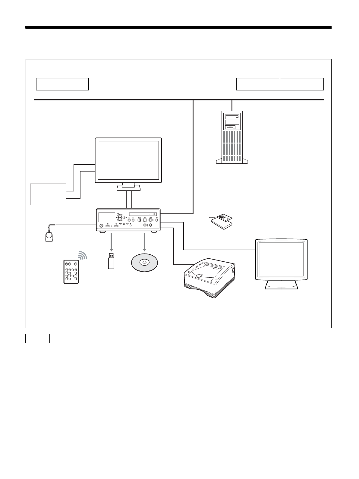
System Configuration Example
Operating room
Endoscopic
device
FS-24 foot
switch
Doctor’s office ICU
Hospital network
File server
HVO-4000ST
Card reader/
barcode reader
Record data to up to
one external storage
RM-M010 infrared remote
control unit
media simultaneously.
Touch panel monitor
Printer
Caution
The FS-24 has an Ingress Protection rating of IPx3. Therefore, do not operate it environments exposed to splashing liquids
(e.g., surgical operating rooms). For safety, use a device with a rating of IPx6 or higher when operating in such
environments.
17
Page 18
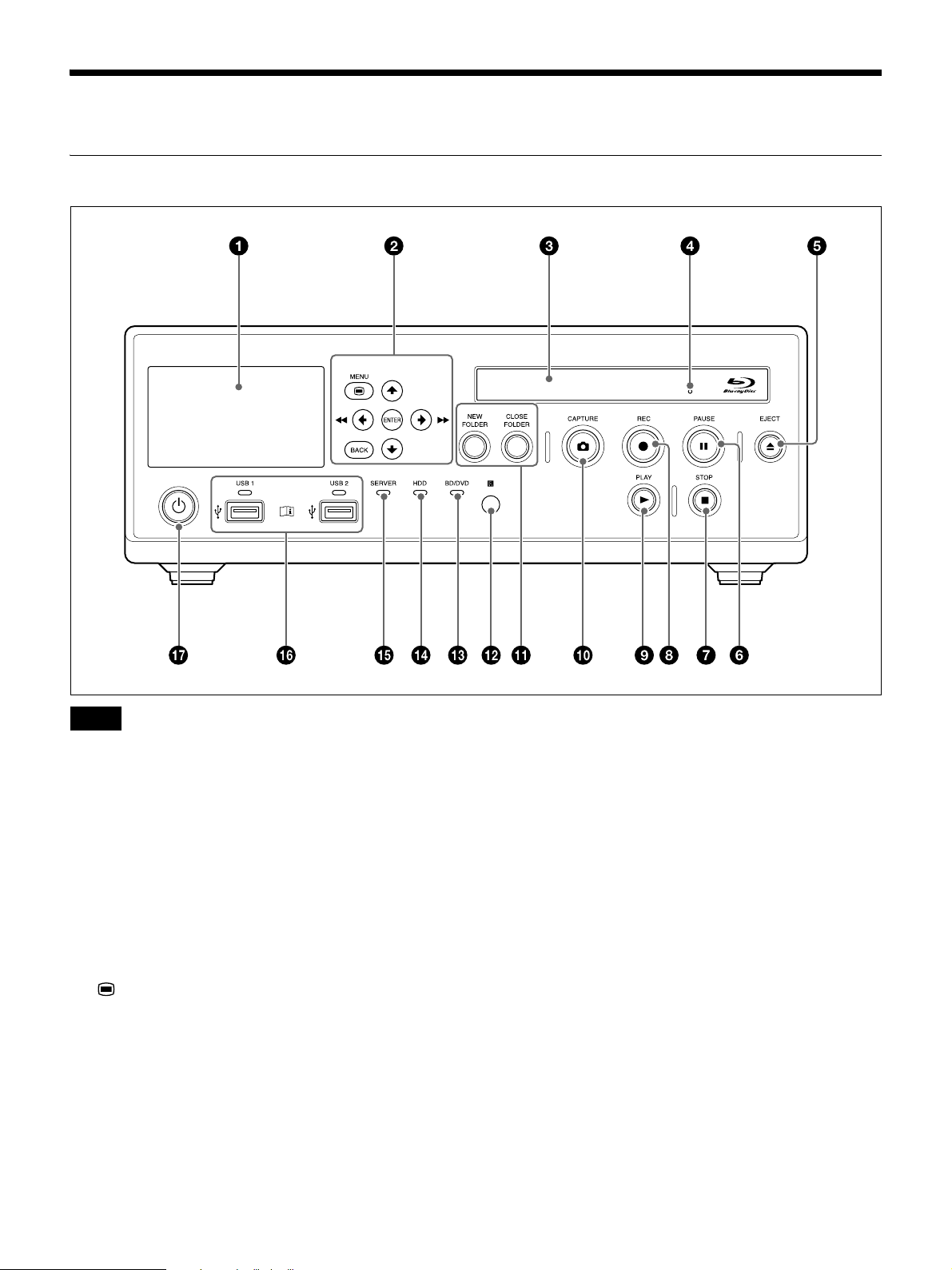
Names and Functions of Parts
Front
Note
Do not touch the laser pickup inside the BD drive
The discharge of static electricity that may result from
touching the pickup may cause the drive to hang up,
preventing the ability to write data. If a hang up occurs,
try turning the recorder off and turning it on again.
a Front panel display
Displays Ch1 input/output videos and still images,
the status of the unit, error messages, etc.
b Menu navigation buttons
Use these to navigate menus.
MENU button
Display or hide the menu.
V button
Use this to move the cursor up or select an item that
is above the current item.
B/m button
Use this to move the cursor left or select an item that
is to the left of the current item.
You can also use this button to rewind during
playback of recorded data.
v button
Use this to move the cursor down or select an item
that is below the current item.
b/M button
Use this to move the cursor right or select an item that
is to the right of the current item.
You can also use this button to fast forward during
playback of recorded data.
ENTER button
Use this to confirm a currently selected menu or item,
and execute operations.
BACK button
Use this to return to a previous screen during menu or
operation screen displays.
When you press this button while nothing is
displayed on the screen, the text that appears on the
front panel display will be hidden.
18
Page 19
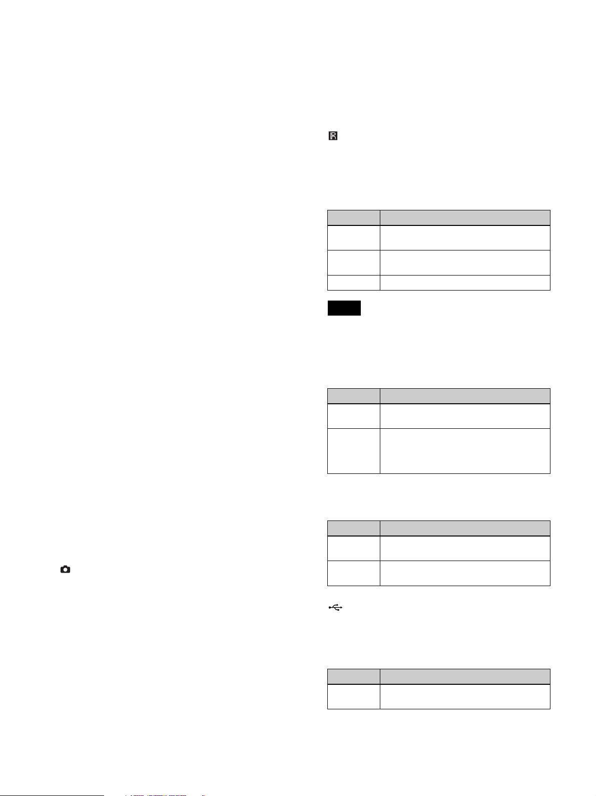
c Disc tray
Insert discs here.
d Emergency eject hole
If the disc tray does not open when you press the Z
EJECT button, insert a long, thin object such as a
straightened paper clip into this hole to open the disc
tray.
e Z EJECT button
Use this to open the disc tray.
f X PAUSE button
Use this while recording is in progress to pause
recording. Press this button again to resume
recording. A chapter separator is also created at the
position in which recording was paused.
You can also use this button to pause playback.
To resume playback, press this button again or press
the B PLAY button.
“PAUSE” appears on the front panel display during
pause.
g x STOP button
Use this to stop recording or playback.
A title separator is also created at the position in
which recording was stopped.
h z REC button
Use this to start video/audio recording.
During recording, “REC” appears on the front panel
display in addition to the recording time.
For details on use, see “Manual Recording”
(page 46).
i B PLAY button
• Use this to play back the most recent recorded data
stored on the internal hard disk, or to play back the
recorded data selected in the [Recording List] or
[Image List] screen.
• Press this button while playback is paused to
resume playback.
j CAPTURE button
Use this to capture still images.
A chapter separator is also created at the position in
which the still image was captured.
For details on use, see “Capture Still Images”
(page 47).
k NEW FOLDER button
Use this to display the [Recording Preparation]
screen to start recording a new surgical procedure or
examination.
For details on use, see “Recording Preparation”
(page 43).
CLOSE FOLDER button
Use this to display the [End Recording] screen which
is used to end surgical procedure or examination
recordings.
For details on use, see “Step 4: End Recording”
(page 42).
l Infrared receiver
Point the infrared remote control unit toward this
receiver.
m BD/DVD indicator
Displays the status of the BD/DVD drive.
Indicator Status
Blinking
green
Lit green The recording area of the BD/DVD disc is
Lit orange An error has occurred.
Note
Data is being written to the BD/DVD disc.
full. Insert a different disc.
You cannot remove the disc when this indicator is
blinking green.
n HDD indicator
Displays the status of the internal hard disk.
Indicator Status
Blinking
green
Lit orange An error has occurred.
Data is being recorded to the internal
hard disk.
The recording area of the internal hard
disk is full. Delete any unnecessary
recorded data.
o SERVER indicator
Displays the server access status.
Indicator Status
Blinking
green
Lit orange An error has occurred.
The server is being accessed.
The recording area of the server is full.
p USB ports/indicators 1 and 2
Connect USB memory devices, external hard disks,
and other USB media here.
The indicators display the status of USB media
access.
Indicator Status
Blinking
green
Data is being written to the USB media.
19
Page 20
Indicator Status
Lit green The recording area of the USB media is
full. Delete any unnecessary recorded
data, or insert different media.
Lit orange An error has occurred.
Note
Never remove USB media when these indicators are
blinking green.
Tip
Supported USB devices
• Use Sony USB media.
• The connectors do not support all USB devices.
• USB hubs and devices with built-in hubs are not
supported.
WARNING
Using this unit for medical purposes
The connectors on this unit are not isolated.
Always use USB-compatible external hard drives and
USB memory devices that operate solely on the
power supplied by the unit.
Connecting a device that operates on an AC power
supply may result in an influx of leakage currents
from the connected device, which may in turn result
in electric shocks to the patient and operator.
If use of such devices cannot be avoided, be sure to
connect an isolation transformer to the power supply
of the connected device or connect an isolator
between the connection cables to isolate the power
supply, and verify that the risk of electric shock from
the system has been sufficiently reduced to levels that
conform to IEC 60601-1 standards.
q 1 (on/standby) switch/indicator
Use this switch to turn on the unit and the front panel
display. Press this switch again to turn off the unit and
enter standby mode.
The indicator indicates the following.
Indicator Status
Off The main power switch on the rear panel
is set to the a (off) position.
Lit orange Standby mode. (The main power switch
on the rear panel is set to the ? (on)
position.)
Lit green The unit is turned on. (The 1 (on/
standby) switch was pressed to turn on
the unit.)
Tip
The indicator will turn off about 15 seconds after the
main power switch on the rear panel is turned off
from the standby state.
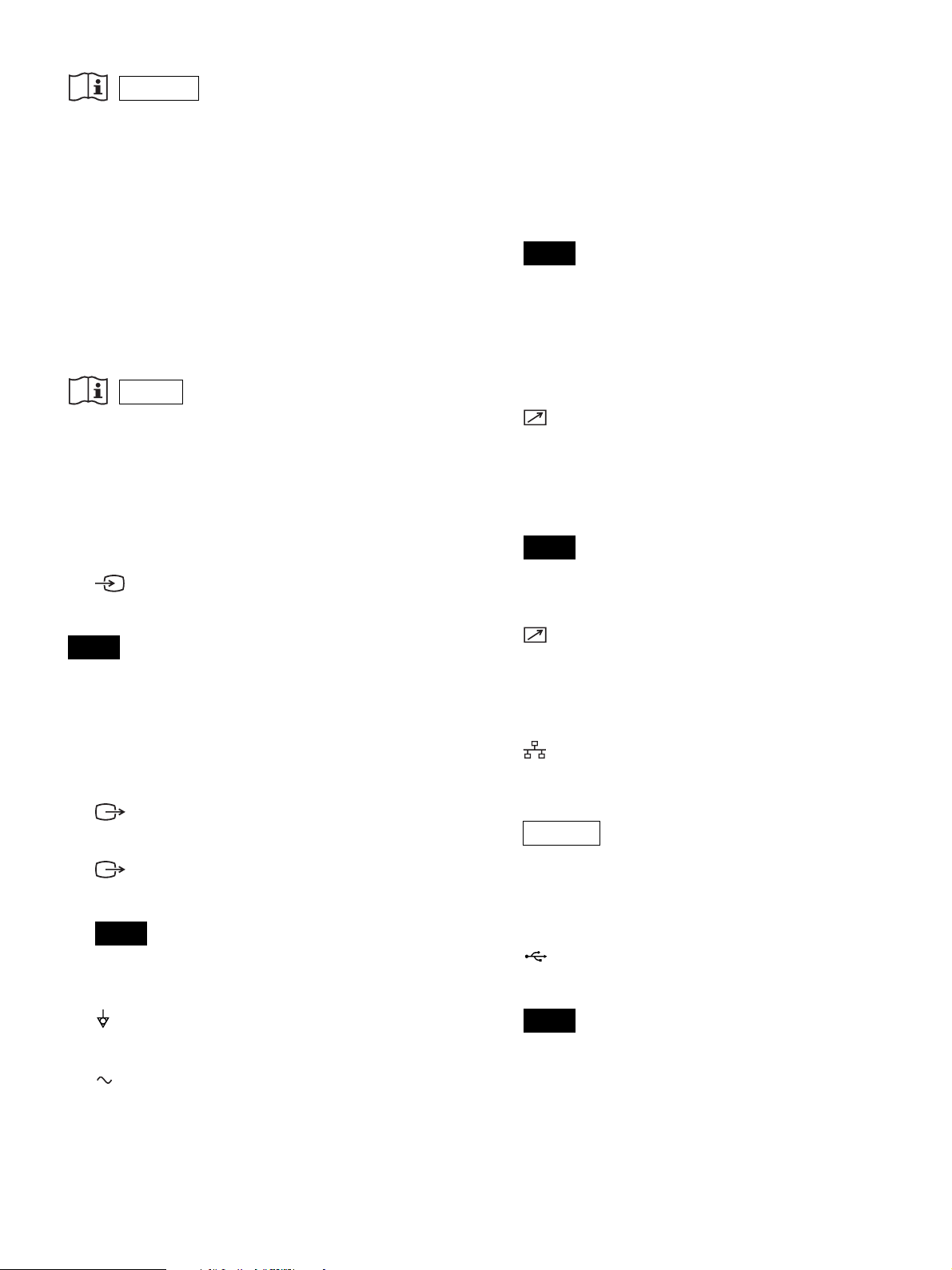
Rear
20
Page 21
WARNING
Using this unit for medical purposes
This equipment’s connectors are not isolated.
Do not connect any device other than one which conforms
to IEC 60601-1.
When an information technology device or AV device
that uses an alternating current is connected, current
leakage may result in an electric shock to the patient or
operator.
If use of such a device is unavoidable, isolate its power
supply by connecting an isolation transformer, or by
connecting an isolator between the connecting cables.
After implementing these measures, confirm that the
reduced risk now conforms to IEC 60601-1.
Caution
Using this unit for medical purposes
Do not come into contact with the terminals of the rear
panel connectors and patients at the same time.
Doing so may result in a generation of voltage that can be
harmful to patients if the unit is malfunctioning.
Always disconnect the power cord before connecting and
disconnecting connectors.
f Main power switch
Set this to the ? (on) position to turn on the power. To
turn off the power, set the switch to the a (off)
position.
During regular use of the unit, leave the main power
switch in the ? (on) position, and use the qj 1 (on/
standby) switch on the front panel of the unit to
switch between operational mode and standby mode.
Note
When you press the qj 1 (on/standby) switch on the
front panel of the unit while the unit is in operational
mode, data is saved before the unit enters standby
mode. Always make sure that the unit is in standby
mode before setting the main power switch to the a
(off) position to turn off the power.
g REMOTE contact switch connectors 1 to 4
(stereo mini jack)
Use these to control the unit via contact switches.
For details on contact switches, see “[Contact
Switch] Tab” (page 65).
Note
a SDI input connectors A to D (BNC type)
Inputs SDI signals (3G SDI).
Tips
• If SDI input images are not displayed, turn on the unit
first and make sure that startup is complete before
turning on the video input device.
• When receiving 4K signals, the four SDI inputs must be
synchronized.
• Embedded audio is not supported.
b SDI output connectors A to D (BNC type)
Outputs SDI signals (3G SDI).
c HDMI output connector (Type A)
Outputs HDMI signals.
Note
We recommend using a Sony HDMI cable (not
supplied).
d Equipotential grounding terminal
Use this for equipotential grounding connections.
e AC IN connector
Connect a power cord (not supplied) here.
Contact switch connector 4 is intended for future
expansions.
h USB port 7 (Type B / USB 2.0)
Use this to perform system controls from an external
device.
For details on system controls, see “[Control] Tab”
(page 64).
i Network connector (RJ-45)
Connect a 1000 Base-T or 100 Base-TX network
cable here.
CAUTION
For safety, do not connect the connector for
peripheral device wiring that might have excessive
voltage to this port. Follow the instructions for this
port.
j USB ports 3 to 6 (Type A / USB 2.0)
Connect USB devices here.
Tip
Supported USB devices
• Use Sony USB media.
• The connectors do not support all USB devices.
• USB hubs and devices with built-in hubs are not
supported.
21
Page 22
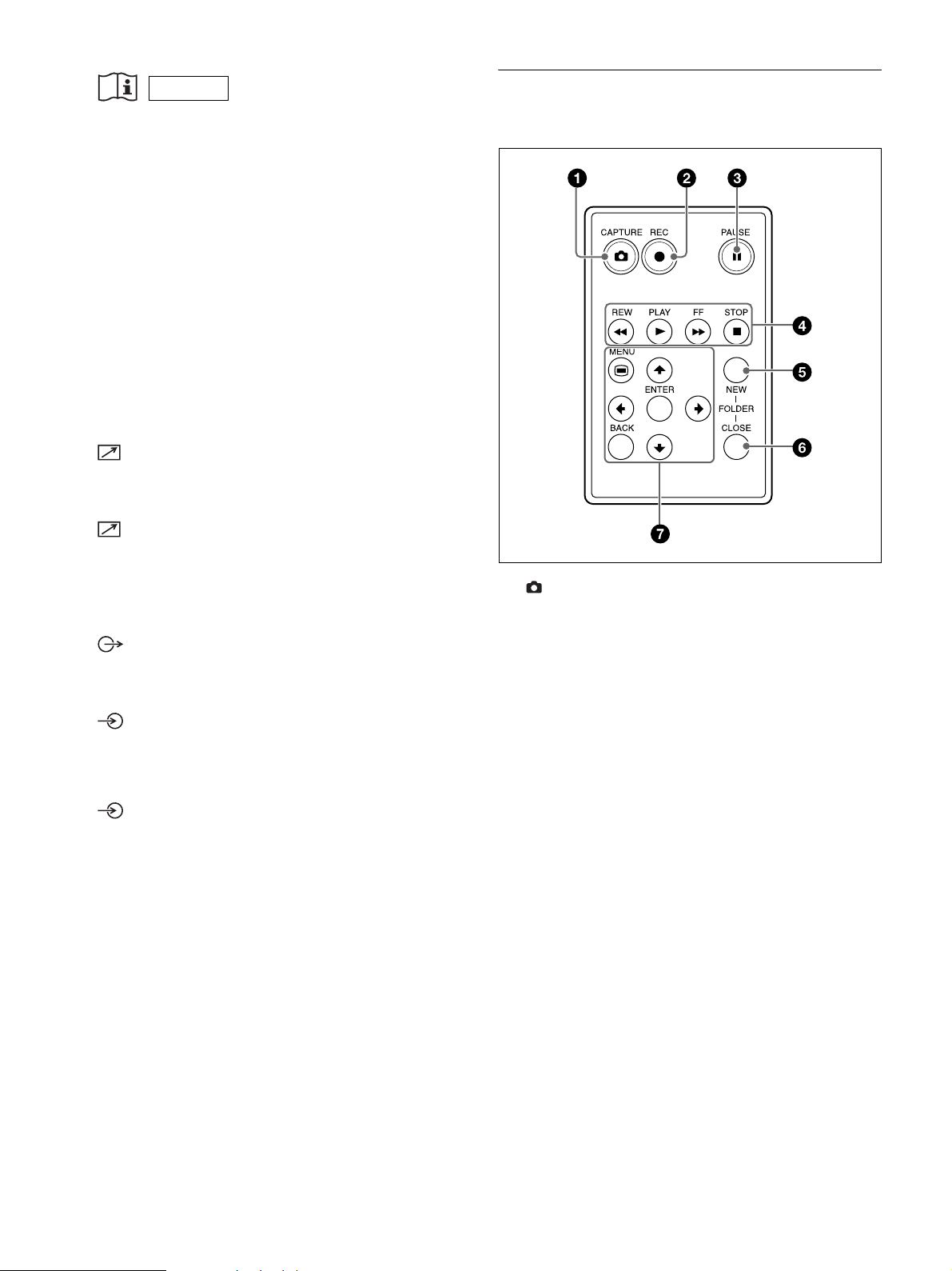
WARNING
Infrared Remote Control Unit (RM-
Using this unit for medical purposes
The connectors on this unit are not isolated.
Always use USB-compatible external hard drives and
USB memory devices that operate solely on the
power supplied by the unit.
Connecting a device that operates on an AC power
supply may result in an influx of leakage currents
from the connected device, which may in turn result
in electric shocks to the patient and operator.
If use of such devices cannot be avoided, be sure to
connect an isolation transformer to the power supply
of the connected device or connect an isolator
between the connection cables to isolate the power
supply, and verify that the risk of electric shock from
the system has been sufficiently reduced to levels that
conform to IEC 60601-1 standards.
k MENU MONITOR connector (15-pin mini D-
sub)
Connect a touch panel monitor or similar device here.
l RS-232C connector (9-pin D-sub)
Use this to perform system controls from an external
device.
For details on system controls, see “[Control] Tab”
(page 64).
m AUDIO (analog audio signal) output
connector (stereo mini jack)
Outputs analog audio signals.
M010)
a CAPTURE button
Use this to capture still images.
A chapter separator is also created at the position in
which the still image was captured.
For details on use, see “Capture Still Images”
(page 47).
n MIC input connector (stereo mini jack)
Inputs analog audio signals from the microphone.
You can configure settings to supply power from the
unit.
AUDIO (analog audio signal) input connector
(LINE) (stereo mini jack)
Inputs analog audio signals.
b z REC button
Use this to start video/audio recording.
During recording, “REC” appears on the front panel
display in addition to the recording time.
For details on use, see “Manual Recording”
(page 46).
c X PAUSE button
Use this while recording is in progress to pause
recording. Press this button again to resume
recording.
A chapter separator is also created at the position in
which recording was paused.
You can also use this button to pause playback.
To resume playback, press this button again or press
the B PLAY button.
“PAUSE” appears on the front panel display during
pause.
d m REW button
Use this to rewind during playback of recorded data.
22
Page 23
B PLAY button
• Use this to play back the most recent recorded data
stored on the internal hard disk, or to play back the
recorded data selected in the [Recording List] or
[Image List] screen.
• Press this button while playback is paused to
resume playback.
BACK button
Use this to return to a previous screen during menu or
operation screen displays.
When you press this button while nothing is
displayed on the screen, the text that appears on the
front panel display will be hidden.
M FF button
Use this to fast forward during playback of recorded
data.
x STOP button
Use this to stop recording or playback.
A title separator is also created at the position in
which recording was stopped.
e NEW FOLDER button
Use this to display the [Recording Preparation]
screen to start recording a new surgical procedure or
examination.
For details on use, see “Recording Preparation”
(page 43).
f CLOSE FOLDER button
Use this to display the [End Recording] screen which
is used to end surgical procedure or examination
recordings.
For details on use, see “Step 4: End Recording”
(page 42).
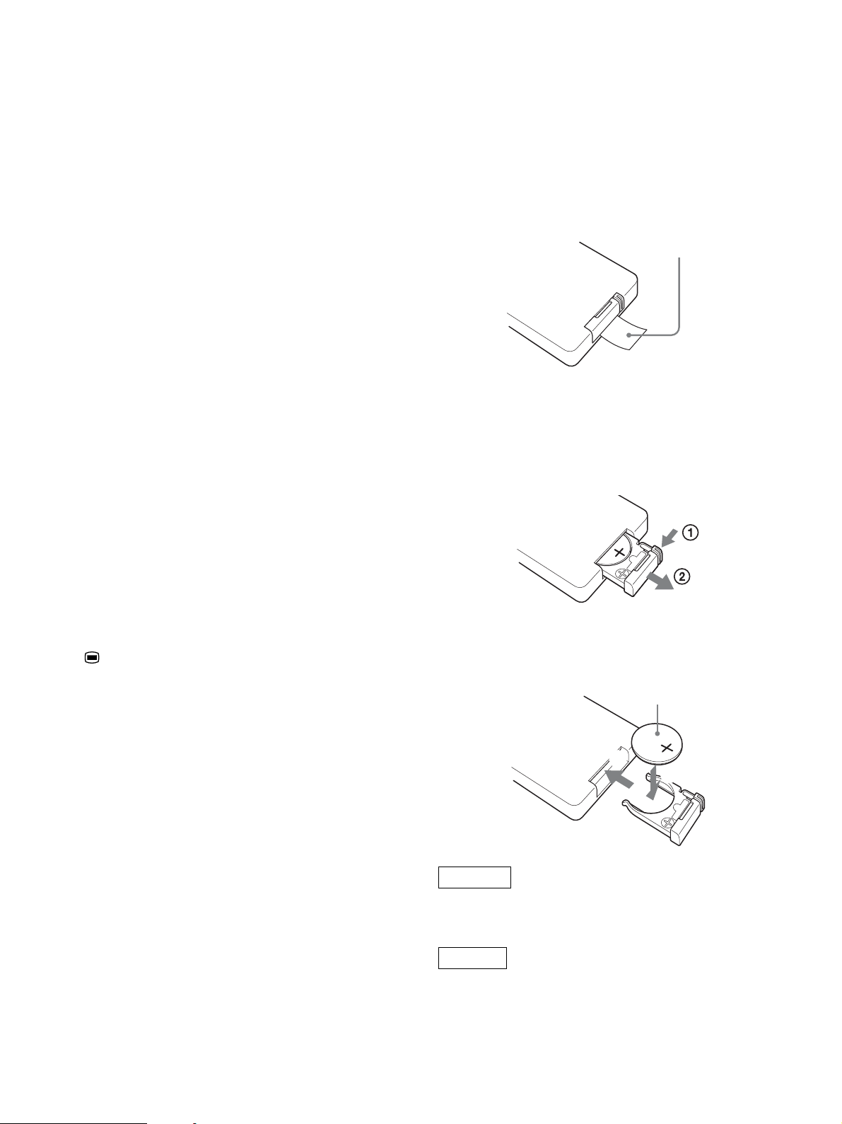
Before using the remote control unit
Remove the insulation sheet.
Insulation sheet
To replace the lithium battery
Use a Sony CR2025 lithium battery. Do not use any other
type of battery with the remote control unit.
1
While holding in the lock lever (1), pull out the
battery holder (2).
g Menu navigation buttons
Use these to navigate menus.
MENU button
Display or hide the menu.
v button
Use this to move the cursor down or select an item
that is below the current item.
b button
Use this to move the cursor right or select an item that
is to the right of the current item.
ENTER button
Use this to confirm a currently selected menu or item,
and execute operations.
B button
Use this to move the cursor left or select an item that
is to the left of the current item.
V button
Use this to move the cursor up or select an item that
is above the current item.
2
Insert the replacement battery with the positive (+)
side facing up (1), and reinsert the battery holder
until it clicks into place (2).
Positive (+) side facing up
2
1
WARNING
Batteries shall not be exposed to excessive heat such as
sunshine, fire or the like.
CAUTION
Danger of explosion if battery is incorrectly replaced.
Replace only with the same or equivalent type
recommended by the manufacturer.
23
Page 24
When you dispose of the battery, you must obey the law
in the relative area or country.
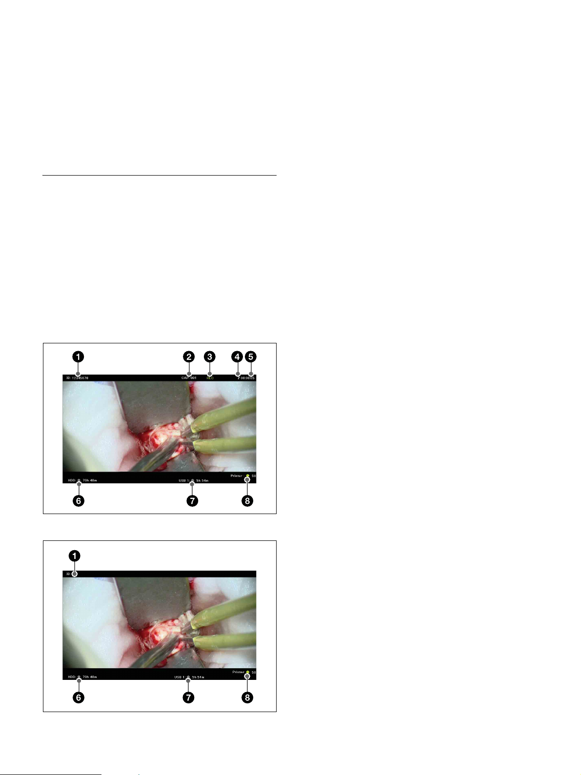
a Patient ID
Displays the patient ID.
Battery lifetime
When the lithium battery output falls, even button presses
may not operate. The average lithium battery lifetime is
about one year, but this depends on the pattern of use. If
pressing the remote control buttons produces absolutely
no effect on this unit, replace the battery, then check the
operation again.
Status Displays
The following information is displayed when the status
display settings are enabled.
The status display settings are configured in the [System
Admin Settings] screen – [Function Settings] screen –
[General 1] tab. For details on this setting, see “[General
1] Tab” (page 60).
Rec status display / idle status display
Rec status displays
b Capture counter
Displays the number of still images captured.
c Recording status
Displays the recording status.
REC: Recording is in progress.
REC PAUSE: Recording has been paused.
REC STOP: Recording preparation is complete or
recording has been stopped.
d Audio recording status
Displays the audio recording status.
9: Audio recording is in progress.
no display: Audio is not being recorded.
e Recording time
The recording time is counted in seconds and
displayed in “HH:MM:SS” a format.
f HDD status
Displays the internal HDD status and the remaining
time.
The status color indicates the following.
Green: Recording is in progress or still image
recording is in progress.
Orange: The maximum number of recorded data
entries has been exceeded or the internal HDD is
full.
Gray: Status other than the above.
Idle status displays
g External media status
Displays the status of the external media and the
remaining capacity time.
The status color indicates the following.
• When transferring to BD/DVD
Green: Transfer or formatting is in progress.
Orange: Additional recording to the BD/DVD is
not possible, an unsupported BD/DVD is
inserted, the maximum number of BD/DVD
exchanges has been exceeded, or a finalized
DVD is inserted.
Gray: Status other than the above.
• When transferring to USB
Green: Transfer is in progress.
Orange: An unsupported USB memory device is
inserted, the maximum number of USB
memory device exchanges has been exceeded,
or a transfer error has occurred.
Gray: Status other than the above.
• When transferring to a server
Green: Transfer is in progress.
Orange: Insufficient server capacity or a transfer
error has occurred.
Gray: Status other than the above.
24
Page 25
h Print status
Displays the printer status and the remaining number
of print sheets.
The status color indicates the following.
Green: Still image printing is in progress.
Orange: A print error has occurred.
Gray: Status other than the above.
Playback status displays
a Patient ID
b Playback status
Displays the playback status.
PLAY: Video playback is in progress.
FF x2 to FF x60: Fast forward at x2 to x60 speed is
in progress.
REW x2 to REW x60: Rewind at x2 to x60 speed
is in progress.
PAUSE: Playback has been paused.
c Video chapter number / still image playback
status
CHAPTER:xxx/xxx: Displays the number of the
chapter being played back.
STILL:xxx/xxx: Displays the number of the still
image being played back.
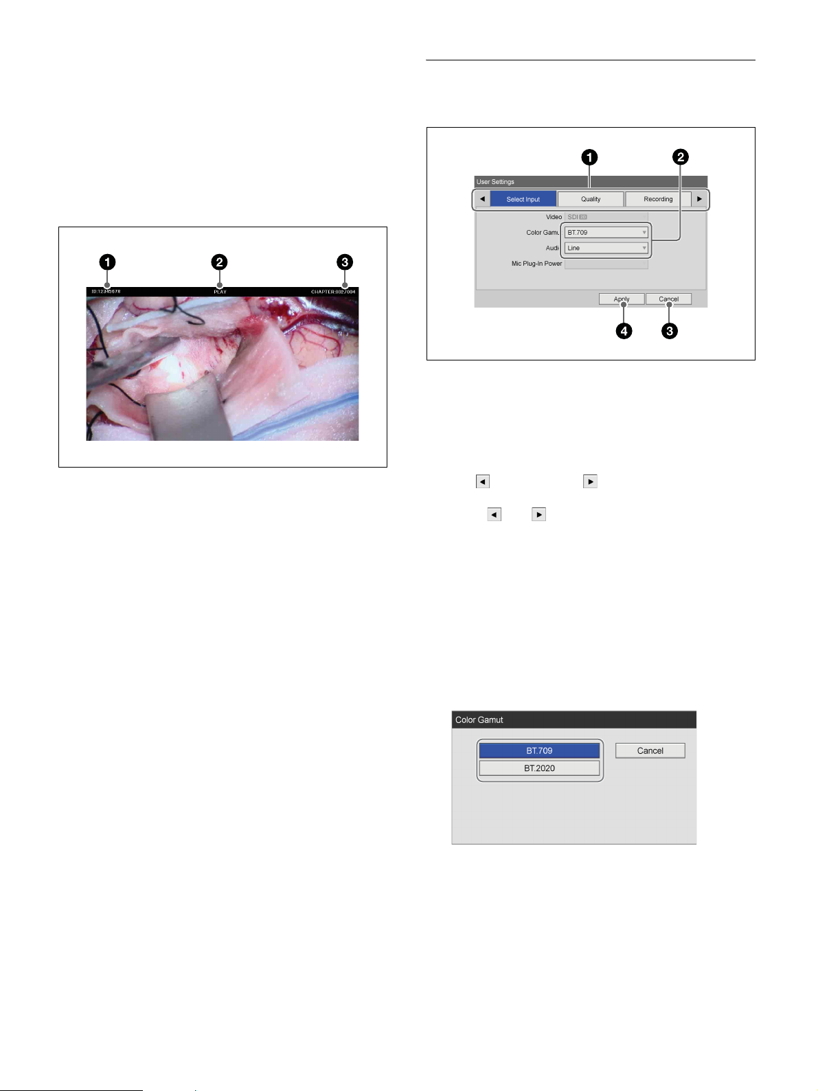
Setting Screens
Example: [User Settings] screen
a Tabs
The setting screens consist of tabs.
To switch between tabs, use the
the front panel or remote control to select the desired
tab.
If additional tabs exist before and after the displayed
tab, (previous) and (next) are also displayed.
The tabs will be displayed in sequence when you
select and .
b Setting item
Use the
press the ENTER button to display the setting screen
for that item. You can select or enter setting values in
the screens that appear.
Example: When selecting a setting value
Select the item, and press the ENTER button.
The previous screen will appear again, and the setting
value will be entered.
V, v, B, and b buttons to select an item, and
B and b buttons on
25
Example: When selecting check boxes
Select the item and press the ENTER button to select
the check box. The check box will be selected/cleared
with each press of the ENTER button. (Multiple
selections can be made.)
When you select [OK] and press the ENTER button,
the previous screen appears again with the setting
value entered.
Page 26
c [Cancel]
Select this button and press the ENTER button to
cancel the settings and close the setting screen.
d [Apply]
Select this button and press the ENTER button to save
the settings and close the setting screen.
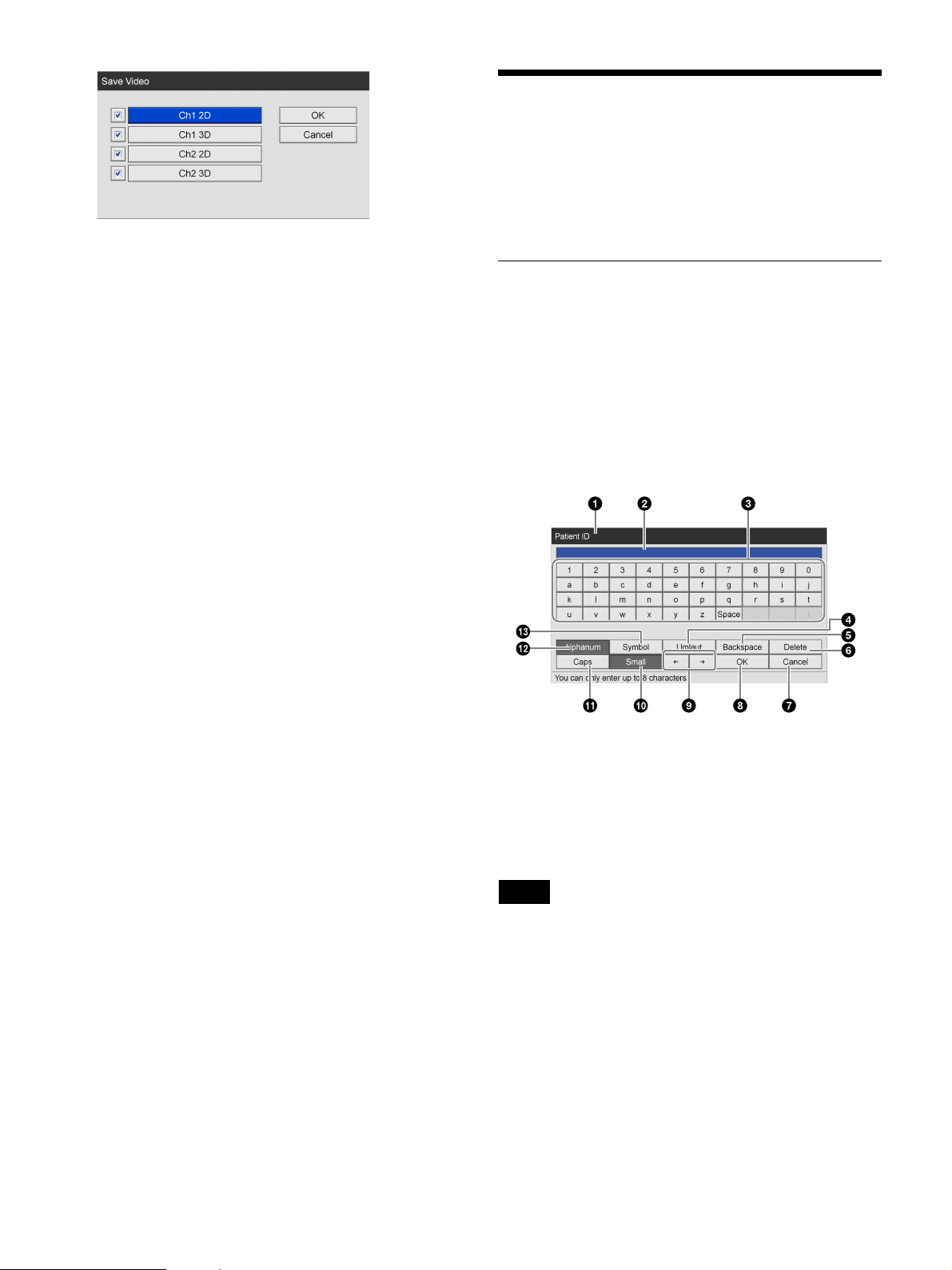
Using the On-Screen Keyboard (Text Entry)
When text entry is necessary, an on-screen keyboard
appears.
Names and Functions of Parts (OnScreen Keyboard)
You can display an alphanumeric, symbol, or umlaut
character set on the on-screen keyboard.
The name and function of each part on the keyboard is as
follows.
Example: On-screen keyboard during
alphanumeric character display
a Title bar
The name of the setting item for which the on-screen
keyboard was opened is displayed here.
b Entry box
Characters selected on the keyboard are entered here.
Tip
Characters input on a hardware keyboard are also entered
here.
c Keyboard
When you select a character you want to input using
the
V, v, B, and b buttons and then press the ENTER
button, the character is entered in the 2 entry box.
d [Umlaut]
Select this and press the ENTER button to switch the
keyboard to umlaut character display.
26
Page 27
e [Backspace]
Select this and press the ENTER button to discard the
character immediately preceding the cursor.
Handling Discs
f [Delete]
Select this and press the ENTER button to discard the
character immediately following the cursor.
g [Cancel]
Select this and press the ENTER button to cancel text
entry and close the on-screen keyboard.
h [OK]
When you select this and press the ENTER button,
the text that appears in the entry box is applied and
input in the settings screen.
i
B/b
Select this and press the ENTER button to move the
cursor one space to the left or right.
j [Small]
Select this and press the ENTER button to switch the
keyboard to lower case display.
k [Caps]
Select this and press the ENTER button to switch the
keyboard to upper case display.
Compatible discs
This unit supports the following BD and DVD discs.
•DVD-R
• BD-R / BD-R DL
• BD-RE / BD-RE DL
Tip
Use Sony discs.
Disc formatting
This unit automatically formats new and previously
unused discs.
Notes on Handling
Handling
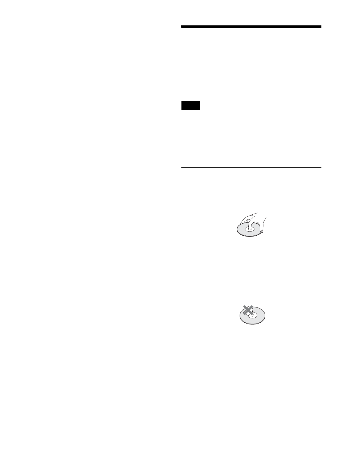
• Do not touch the recording or playback surface of the
disc. Handle the disc by its edge.
l [Alphanum]
Select this and press the ENTER button to switch the
keyboard to alphanumeric character display.
m [Symbol]
Select this and press the ENTER button to switch the
keyboard to symbol display.
• Do not use the following types of disc. Doing so may
cause the unit to malfunction.
– A disc on which a paper label or a seal is attached
– A disc on which the glue of cellophane tape or a label,
or on which a portion of a label still remains
– A cracked disc
– A cracked disc which has been mended using glue (or
a similar substance)
Storage
• Do not store discs where they may be subjected to direct
sunlight, or in other places where the temperature or
humidity is high.
• Store discs in their cases.
• Finger prints or dust accumulated on the disc cause
deterioration of picture quality. Keep the disc clean.
Cleaning
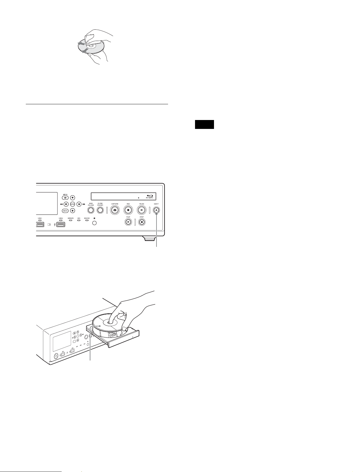
• Clean the disc with a soft cloth, wiping it from the
center out. If the dust is heavy, wipe it with a soft cloth
moistened with water, then wipe off the water with a
dry cloth.
27
Page 28
• Do not use solvents such as benzene, thinner,
commercially available record cleaners, or anti-static
spray. Using these products may damage discs.
Inserting and Removing Discs
To insert a disc
1
Turn the unit on.
For details, see “To turn on the unit” (page 29).
2
Press the Z EJECT button.
the menu screen. Remove the disc, and insert a
compatible disc.
To remove a disc
1
Press the Z EJECT button while the unit is turned on.
The disc tray opens.
2
Remove the disc.
3
Gently push in the disc tray to close it.
Tip
When simultaneously saving to a BD/DVD, the disc
tray cannot be opened while recording is in progress
or paused.
Z EJECT button
The disc tray opens.
3
Insert the disc.
Data side facing down
4
Gently push in the disc tray.
The disc tray closes.
When an incompatible disc is inserted
The BD/DVD indicator lights orange. A message
notifying you of the incompatible media also appears on
28
Page 29
Preparation
Chapter
2
Connections
1
Connect a power cord (not supplied) to the AC IN
connector on the rear of the unit.
2
Connect the output signal of the medical equipment
to SDI-IN connectors A to D on the rear of the unit.
3
Connect the plug on the power cord to an AC power
supply.
4
Turn on the medical equipment that will act as the
signal source.
Turning the Unit On and Off
To turn on the unit
1
Set the main power switch on the rear panel to the ?
(on) position.
2
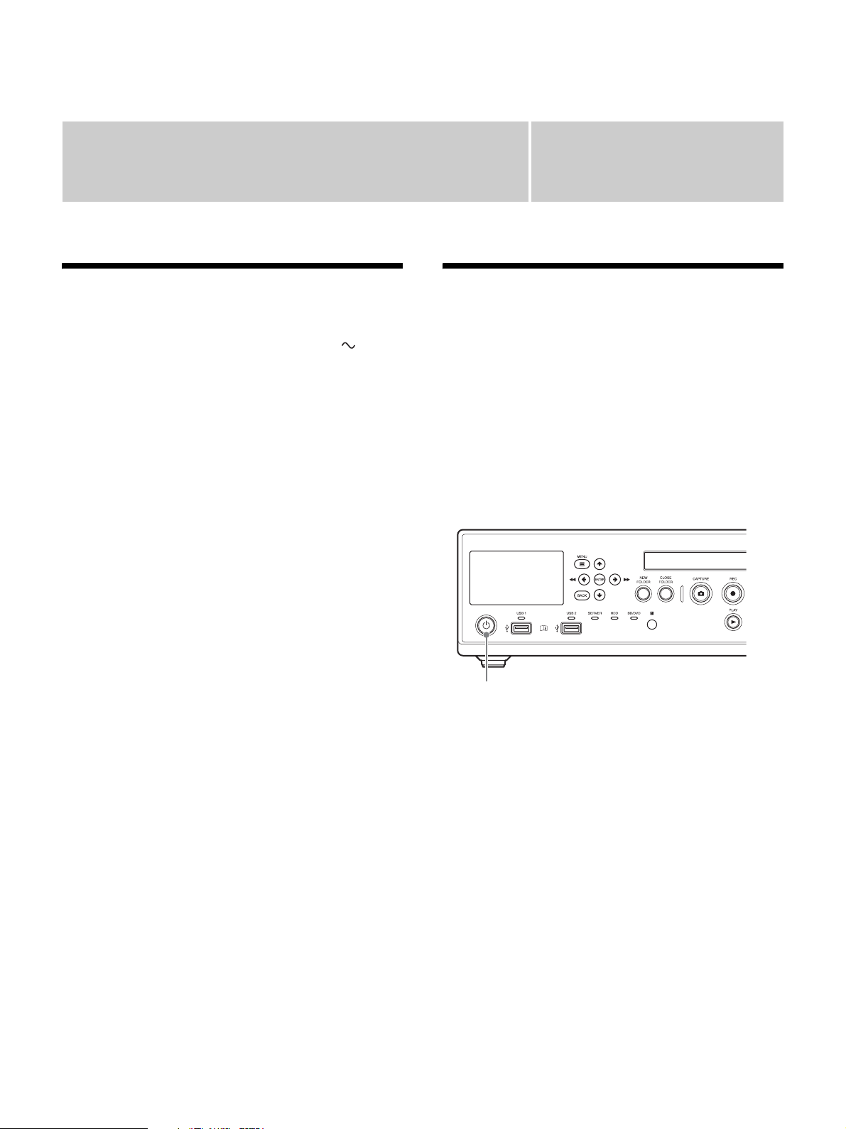
Press the 1 (on/standby) switch on the front panel of
the unit.
Front panel
1 (on/standby) switch
A splash screen appears on the front panel display when
the unit turns on.
After “BOOTING...” and then the patient ID, current
date, and other information appear on the front panel
display, operations can be performed.
To turn on power or enter standby during normal
operation
Use the 1 (on/standby) switch on the front panel to
switch between turning the unit on and entering the
standby mode.
“FINISHING” appears on the front panel display while
the unit is shutting down. “GOOD BYE” appears and
disappears after shutdown is complete, and the unit enters
standby mode.
During long periods of disuse
Turn off the main power switch on the rear panel of the
unit when not using the unit for long periods of time.
29
Page 30

1
Press the 1 (on/standby) switch on the front panel of
the unit to enter standby mode.
The 1 (on/standby) indicator lights orange.
2
Set the main power switch on the rear panel of the
unit to the a (off) position.
The power is turned off.
Tip
To completely shut off the power supply, set the main
power switch to the a (off) position, and then disconnect
the power cord.
Configuring System Settings
Be sure to configure the system settings before you begin
operating the unit. The system settings should be
configured by the system administrator.
For details on system settings, see “System Administrator
Settings” (page 56).
Tip
If the system administrator settings are not configured,
operations may not be performed as intended in some
cases.
30
Page 31
Configuring Recording Settings (User Settings)
Configure input signal and image quality settings in the
[User Settings] screen.
You can navigate menus using the navigation buttons on
the front panel of the unit.
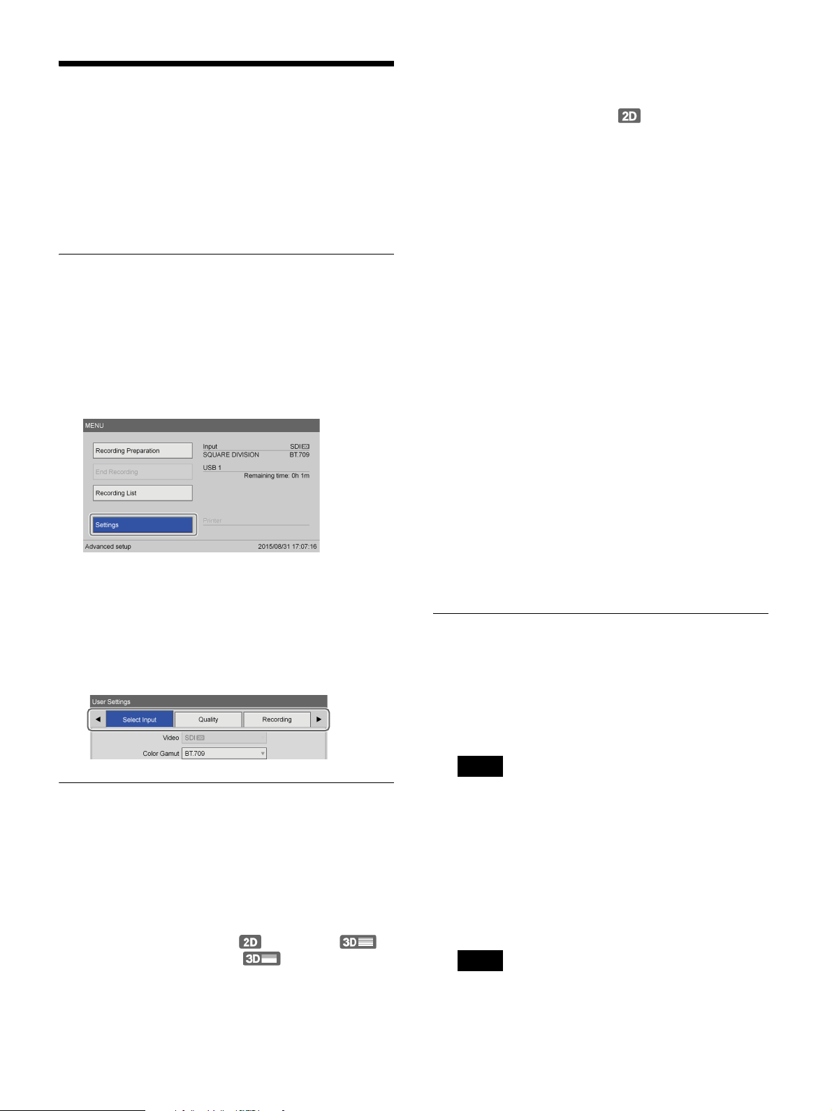
Displaying the [User Settings]
Screen
1
Press the MENU button.
The [MENU] screen appears.
[Function Settings] screen – [Input Detection] tab.
When [Auto] is selected, the automatically detected
input signal will be displayed.
The default setting is [SDI ] (2D).
[Color Gamut]
Select the color gamut for the input signal.
You can select from [BT.709] and [BT.2020].
This item is available when [Color Gamut] is set to
[Manual] in the [System Admin Settings] screen [Function Settings] screen - [Input Detection] tab.
When [Auto] is selected, the automatically detected
color gamut will be displayed.
The default setting is [BT.2020].
[Audio]
Select the audio input format.
You can select from [LINE] and [MIC].
The default setting is [LINE].
2
Select [Settings], and press the ENTER button.
The [Settings] screen appears.
3
Select [User Settings], and press the ENTER button.
The [User Settings] screen appears
4
Select a tab, and configure the settings as necessary.
[Mic Plug-In Power]
Select whether to supply power to the microphone
from the unit.
This item is available when [Audio] is set to [MIC].
The default setting is [Not Used].
You can configure the voltage that is supplied in the
[System Admin Settings].
2
To configure image quality settings, proceed to
“Configuring Image Quality Settings” (page 31).
If you are finished configuring settings, select
[Apply] and press the ENTER button.
Configuring Image Quality Settings
Configure image quality settings for videos and still
images.
1
Display the [Quality] tab, and configure video
settings in the [Video] area.
Tip
Configuring Input Signal Settings
Select the video and audio input signals.
1
Display the [Select Input] tab, and configure each
setting.
[Video]
Select the video input signal.
You can select from [SDI ] (2D), [SDI ]
(3D line-by-line), and [3D ] (3D top-andbottom).
This item is available when [2D/3D] is set to
[Manual] in the [System Admin Settings] screen –
The recording capacities displayed in [Rec Time] and
[Rec Quantity] are estimations for recording both
Ch1 and Ch2 images to single-layer BD discs
(25 GB).
[Quality]
Select the video recording quality.
You can select form [Best], [High], and [Standard].
The default setting is [High].
Tip
The setting specified here will become the default
setting for [Video Quality] in the [Recording
Preparation] screen.
31
Page 32

2
Configure still image settings in the [Still] area.
[Format]
Select the still image format (file format).
You can select from [Bitmap], [TIFF], and [JPEG].
The default setting is [Bitmap].
[Quality]
Select the still image (JPEG) recording quality.
You can select form [Best], [High], and [Standard].
This item is available when [Format] is set to [JPEG].
The default setting is [High].
[Capture]
Displays the still image format used during image
capture.
This is fixed at [Frame] on the unit.
3
To configure recording settings, proceed to
“Configuring Recording Settings (User Settings)”
(page 31).
If you are finished configuring settings, select
[Apply] and press the ENTER button.
[Convert Color Gamut]
Select the conversion format for the recorded color
depth.
You can select from [Do Not Convert], [Ch1/Ch2 to
BT.709] and [Ch2 to BT.709].
The default setting is [Ch2 to BT.709].
[4K Convert Mode]
Select the method used to convert to 3840×2160
resolution when 4096×2160 resolution signals are
input.
You can select from [Cut] and [Downconvert].
The default setting is [Cut].
For details on the actual images that are converted
when [Cut] or [Downconvert] is configured, see “4K
Convert Modes” (page 37).
Note
When using 3D input signals, [Cut] mode will be
used regardless of the [4K Convert Mode] setting.
2
To configure save settings, proceed to “Configuring
Save Settings” (page 32).
Configuring Recording Settings
1
Display the [Recording] tab, and configure recording
settings.
[Ch1/Ch2 Rec Mode]
Select the recording mode.
You can select from [Ch1 Rec] and [Ch1/Ch2 Simul
Rec].
The default setting is [Ch1/Ch2 Simul Rec].
For details on Ch1/Ch2 simultaneous recording, see
“Using the Ch1/Ch2 Simultaneous Recording
Function” (page 48).
[Ch2 Rec Format]
Select 3D or 2D for the Ch2 recording format.
Tips
• When [Ch1/Ch2 Rec Mode] is set to [Ch1/Ch2
Simul Rec], the [Link On] (Ch1/Ch2 link) setting
for the touch panel monitor will be turned on
(green).
• 3D recording will be performed according to the
input signal format. However, images will be
recorded in top-and-bottom format when the input
is a line-by-line format.
• When [CMS Mode] is set to [Use] in the [System
Admin Settings] screen – [Function Settings]
screen – [CMS] tab, [Ch1/Ch2 Rec Mode] will be
fixed at [Ch1/Ch2 Simul Rec]. In addition, [Ch2
Rec Format] will be fixed at its current setting.
If you are finished configuring settings, select
[Apply] and press the ENTER button.
Configuring Save Settings
Configure settings related to storage destinations for
recorded data and simultaneous transfer, and specify
whether to output metadata.
1
Display the [External Storage 1] tab, and configure
settings related to storage destinations for recorded
data.
[Ch1 External Storage]
Select the external storage media that will be used
when performing simultaneous recording.
You can select from [Not Specified], [BD/DVD],
[USB 1], [USB 2], [SERVER], and [Auto-Detect].
The default setting is [Not Specified].
When [CMS Mode] is set to [Use] in the [System
Admin Settings] screen – [Function Settings] screen
– [CMS] tab, the setting will be fixed at the current
selection.
[Ch2 External Storage]
The external storage media selected in [Ch1 External
Storage] appears here.
[Record Save to Media]
Select the external storage media that will be used
when copying recording lists and image lists from the
[Recording List] and [Image List] screens.
32
Page 33

You can select from [BD/DVD], [USB 1], [USB 2],
and [SERVER].
The default setting is [USB 1].
[Folder Structure]
Select the directory structure that will be used when
writing to external destinations.
You can select from [Date + Patient ID] and [Patient
ID].
The default setting is [Date + Patient ID].
When [CMS Mode] is set to [Use] in the [System
Admin Settings] screen – [Function Settings] screen
– [CMS] tab, the setting will be fixed at the current
selection.
Tip
[Metadata Output]
Select the check boxes of the metadata items you
want to transfer to the external media. (Multiple
selections can be made.)
You can select from [Recording Date], [Patient
Info.], [Doctor], [Case], and [Facility Name].
None of the check boxes are selected under default
settings.
Tips
• Metadata is saved to the uppermost directory of the
recorded data folder.
• When [Patient Info.] is selected, the patient’s ID,
name, gender, and date of birth will be output as
metadata.
When recorded data with the same patient ID is
created, a new recording date folder is created under
the patient ID folder, and the recorded data is saved to
the new folder.
2
Display the [External Storage 2] tab, and configure
settings related to simultaneous transfer.
[Save Video]
Select the check boxes of the video formats that will
be simultaneously transferred. (Multiple selections
can be made.)
You can select from [Ch1 2D], [Ch1 3D], [Ch2 2D],
and [Ch2 3D].
All of the check boxes are selected under default
settings.
[Save Still]
Select the check boxes of the storage formats for 3D
still images. (Multiple selections can be made.)
You can select from [3D], [2D], [Convert to 2D
DICOM], [2D Left], [Convert to 2D DICOM Left],
[2D Right], and [Convert to 2D DICOM Right].
All of the check boxes are selected under default
settings.
[Metadata Format]
Displays the format of the metadata outputs.
[Encryption]
Select whether to encrypt the metadata that is output.
The default setting is [Not Used].
[Key]
This item is available when [Encryption] is set to
[Use].
Enter the encryption key using 32 hexadecimal digits.
Tip
When [CMS Mode] is set to [Use] in the [System
Admin Settings] screen – [Function Settings] screen
– [CMS] tab, the setting will be fixed at the current
selection and cannot be changed.
4
To configure print settings, proceed to “Configuring
Print Settings” (page 33).
If you are finished configuring settings, select
[Apply] and press the ENTER button.
Tips
• When [Save Still] is set to [3D], the data will be
saved in MPF format.
• When none of the check boxes are selected, [Save
Video] and [Save Still] will be blank. When
multiple formats are selected, they will be
displayed with slashes (/) used as separators. If the
entire text cannot be displayed, “...” will be
displayed.
3
Display the [Metadata] tab, and configure metadata
output settings.
Configuring Print Settings
Configure print settings for still images.
The unit supports connection and use of the Sony UPDR80MD printer.
Tip
You can select the printer for use from the [System
Admin Settings] screen – [Device Settings] screen –
[Device 1] tab.
For details on this setting, see “[Device 1] Tab”
(page 62).
33
Page 34

1
Display the [Print 1] tab, and configure settings
related to print methods and items to be printed.
The name of the currently connected printer appears
in the [Printer] box.
[Layout]
Select the number of still images to print on each
sheet.
For the portrait orientation
You can select from 1 image (1 × 1), 2 images (1 × 2),
4 images (2 × 2), 6 images (2 × 3), 8 images (2 × 4),
9 images (3 × 3), 12 images (3 × 4), 15 images (3 ×
5), or 18 images (3 × 6).
The default setting is [6 images (2 × 3)].
[Orientation]
Select the orientation for printing.
The default setting is [Portrait].
[Copies]
Specify the number of copies to print (1 to 10).
The default setting is [1].
3
To configure screen display settings, proceed to
“Configuring Other Settings” (page 34).
If you are finished configuring settings, select
[Apply] and press the ENTER button.
Configuring Other Settings
For the landscape orientation
You can select from 1 image (1 × 1), 2 images (2 × 1),
4 images (2 × 2), 6 images (3 × 2), 8 images (4 × 2),
9 images (3 × 3), 12 images (4 × 3), 15 images (5 ×
3), or 18 images (6 × 3).
The default setting is [6 images (3 × 2)].
[Auto Print]
Select whether to print automatically at the moment a
still image is captured.
The default setting is [Not Used].
[Add. Info.]
Select the check boxes of the additional information
items you want to print. (Multiple selections can be
made.)
You can select from [Recording Date], [Patient
Info.], [Doctor], [Case], [Recording Timestamp],
[Logo], [Facility Name], and [Watermark].
None of the check boxes are selected under default
settings.
[Watermark]
Select whether to print watermarks.
Configure settings related to the screen displays.
1
Display the [Other] tab, and configure the following
settings.
[Menu Display]
Select 2D or 3D for the menu screen display format.
The default setting is [2D].
[Select Right/Left of Image]
Select which image (left or right) to use for 2D
recorded data when recording still images or
recording simultaneously.
The default setting is [Left].
2
When you finish configuration, select [Apply] and
press the ENTER button.
The [Settings] screen appears again.
Tip
To print watermarks or logos, you must import
watermark or logo files that were created in the
proper format beforehand. You can import
watermark or logo files from the [System Admin
Settings] screen – [Device Settings] screen – [Device
1] tab.
For details on importing, see “[Import Watermark]”
(page 63) and “[Import Logo]” (page 63).
2
Display the [Print 2] tab, and configure settings
related to paper size and print quantity.
[Paper]
Select the printer’s paper size.
The default setting is [Letter].
34
Page 35
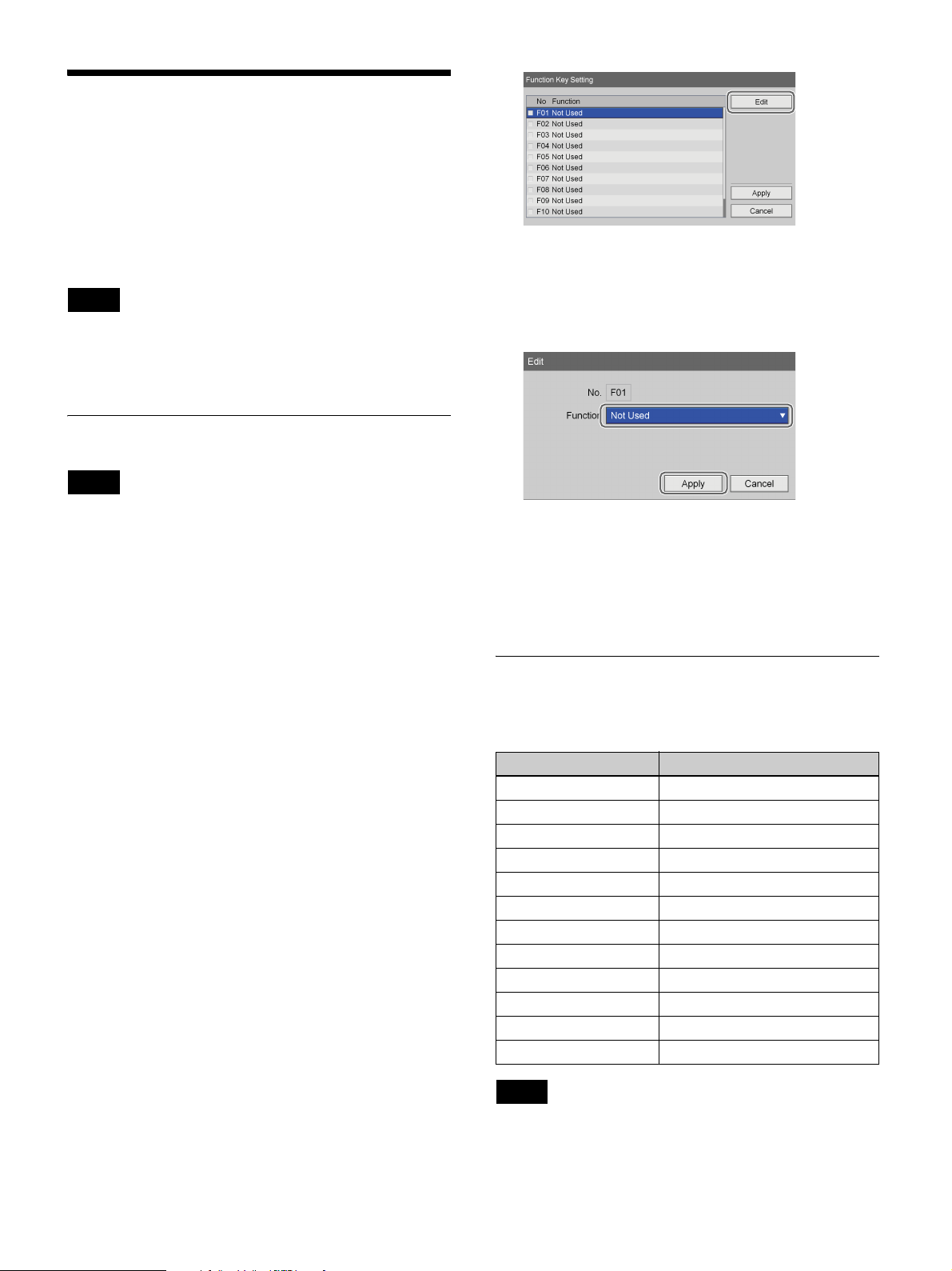
Function Keys
When using the unit, you can assign certain functions
(recording, playback, etc.) to the function keys (F1 to
F12) at the top of a keyboard and perform these functions
with a single keystroke.
We recommend assigning frequently used functions
based on your working environment.
Tip
To perform controls for only Ch2 without the use of a
touch panel monitor, the Ch2 controls must be assigned to
function keys beforehand.
Using Function Keys
Tip
The [Edit] screen appears.
8
Select the functions to assign to the function keys
under [Function], select [Apply], and then press the
ENTER button.
The function keys are enabled only when the hard
keyboard mode is enabled.
1
Press the MENU button.
The [MENU] screen appears.
2
Select [Settings], and press the ENTER button.
The [Settings] screen appears.
3
Select [System Admin Settings], and press the
ENTER button.
The [System Admin Settings] screen appears
4
Select [Device Settings], and press the ENTER
button.
The [Device Settings] screen appears.
5
Display the [Device 2] tab, and set [Keyboard Mode]
to [Hard Keyboard].
6
Select [Advanced] for [Keyboard Mode], and press
the ENTER button.
The [Function Key Setting] screen appears.
7
Select the check boxes of the necessary function keys,
select [Edit], and then press the ENTER button.
The [Function Key Setting] screen appears again.
9
Select [Apply], and press the ENTER button.
The [Function Key Setting] screen closes, and the
[Device 2] tab appears again.
Factory Assigned Functions
The following functions are assigned to the function keys
under factory default conditions.
Function Keys Function
F1 Rec Prep / New Folder
F2 Playback
F3 Fast forward
F4 Rewind
F5 Stop
F6 Pause
F7 Record
F8 Capture
F9 Call list
F10 Add to list
F11 Set Chapter
F12 Close Folder
Tip
The following functions operate as follows.
• [Rec Prep / New Folder]: Display the [Recording
Preparation] screen. A new folder is created.
35
Page 36

• [Record]: Record video and audio.
• [Set Chapter]: Insert a chapter separator without saving
a still image of the recording.
• [Close Folder]: End the recording session.
Other Assignable Functions
Aside from the factory assigned functions, the following
functions can also be assigned to the function keys.
• [Audio Rec On]: Record audio.
• [Audio Rec Off]: Disable audio recording.
• [Menu Display]: Display the [MENU] screen.
• [Chapter Next]: Jump forward to the next chapter.
• [Chapter Back]: Jump back to the previous chapter.
• [1 GOP Next]: Jump forward to the next GOP.
• [1 GOP Back]: Jump back to the previous GOP.
• [Eject]: Eject the inserted disc.
• [Rec List Display]: Display the [Recording List] screen.
• [Status Display On]: Display the unit’s operation status
(i.e., recording, play, pause).
• [Status Display Off]: Hide the unit’s operation status
(i.e., recording, play, pause).
• [Test Record]: Perform a test recording.
• [Ch2 Rec]: Start Ch2 recording.
• [Ch2 Stop]: Stop Ch2 recording or playback.
• [Ch2 Play]: Play back Ch2 recorded data.
• [Ch2 Pause]: Pause Ch2 recording or playback.
36
Page 37
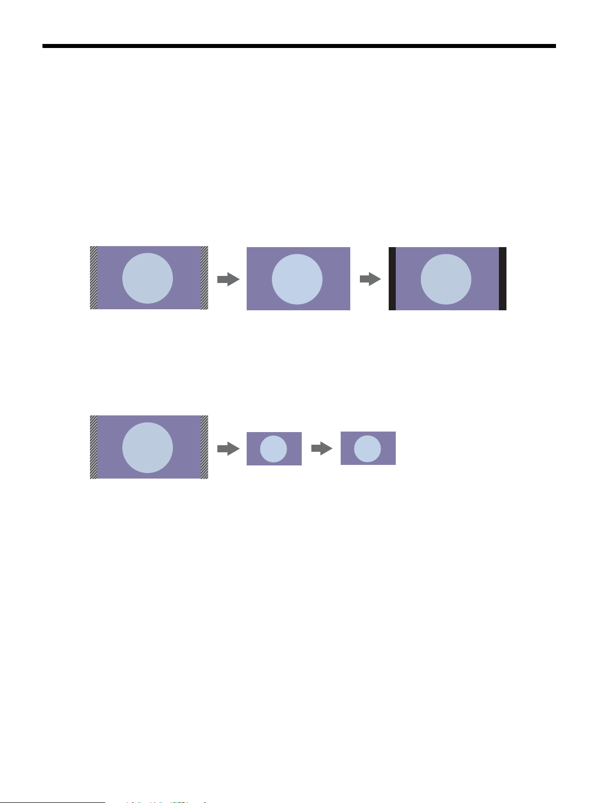
4K Convert Modes
The following image conversions are performed when [Cut] and [Downconvert] are selected for [4K Convert Mode].
You can configure the [4K Convert Mode] setting in the [User Settings] screen - [Recording] tab. For details on this
setting, see “Configuring Recording Settings” (page 32).
[Cut] mode
4K t 4K conversion
• The input image is recorded with 128 pixels cut on both the left and right sides (shaded area in illustration).
• The image is output with black bars (128 pixel width) added to the left and right.
Input image
(4096 × 2160)
Recorded image
(3840 × 2160)
Output image
(4096 × 2160)
Ch1
4K t 2K conversion
• The input image is recorded with 128 pixels cut on each of the left and right sides with its height and width reduced to
1/2 size.
• The recorded image is output as it is recorded.
Input image
(4096 × 2160)
Recorded image
(1920 × 1080)
Output image
(1920 × 1080)
Ch2
[Downconvert] mode
4K t 4K conversion
• The input image is recorded in reduced size with its original aspect ratio and black bars added to the top and bottom (67
and 68 pixel height respectively).
• For SDI outputs, the black bars are removed and the image is expanded to its original resolution.
• For HDMI outputs, black bars (128 pixel width) are added to the left and right of the recorded image.
37
Page 38
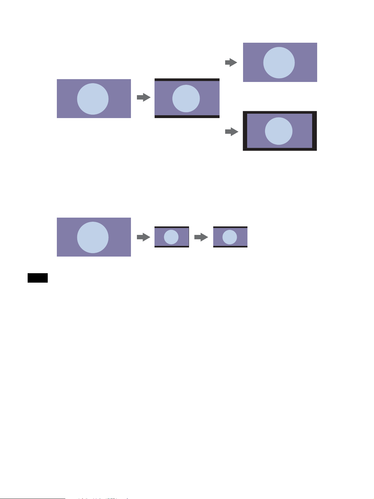
Output image
(4096 × 2160)
Input image
(4096 × 2160)
Recorded image
(3840 × 2160)
SDI
Output image
(4096 × 2160)
HDMI
Ch1
4K t 2K conversion
• The input image is recorded with its height and width reduced to 1/2.1 size and black bars added to the top and bottom
(33.5 and 34 pixel height respectively).
• The recorded image is output as it is recorded.
Input image
(4096 × 2160)
Recorded image
(1920 × 1080)
Output image
(1920 × 1080)
Ch2
Note
When using 3D input signals, [Cut] mode will be used regardless of the [4K Convert Mode] setting.
38
Page 39
Basic Recorder
Operations
Operation Flow
This chapter describes how to record and play back
videos and capture still images while viewing the display
on the front panel of the unit and using only the buttons
on the front panel.
Step 1:
Record
Step 2:
Capture Still
Images
Step 3:
Quick
Playback
Step 4:
End
Recording
Use the buttons on front panel of the unit
to perform manual recording.
v
Capture still images from live image
transmissions.
v
Play back recently recorded data.
v
End recording to the internal HDD, and
end transfer to external media.
Chapter
Tip
If an input signal is interrupted, a chapter separator will be
inserted when it is restored. When saving to external
media, files will be separated by chapters.
3
For details on recording preparation, recording, and
playback operations, see “Chapter 4 Recording and
Playback” (page 43).
Overview of recorded data
“Recorded data” on this unit refers to the data recorded
from the time a “new folder” is created (i.e., when
recording is started) to the time “close folder” is
performed. Recorded data entries include titles. A single
recorded data entry can include multiple titles. A title is
created whenever a stop operation is performed during
recording.
Titles can consist of video data or captured still images.
Up to 15,000 recorded data entries can be registered on
the unit.
A single recorded data entry can include up to 255 titles.
39
Page 40
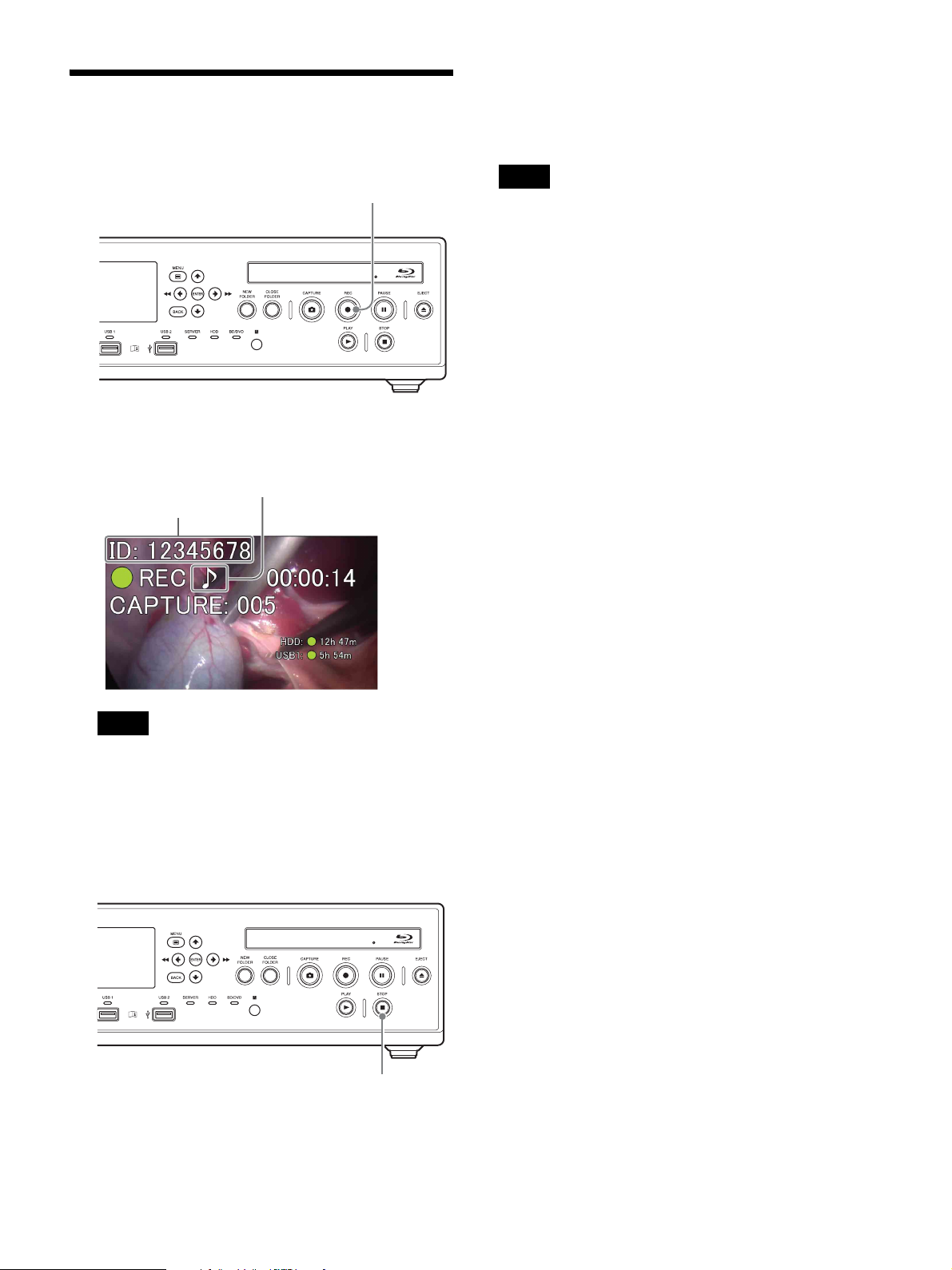
Step 1: Record
z
1
Press the z REC button.
REC button
Recording starts.
“REC” appears while recording is in progress.
This appears when audio is
also being recorded.
Patient ID
If the surgical procedure or examination is finished
and you want to end the recording session, proceed to
“Step 4: End Recording” (page 42) and perform the
recording end procedure.
Tip
If you press the z REC button again, recording will start
again as a new recorded data entry.
Tip
If images are recorded and patient information has
not been entered in the [Recording Preparation]
screen, patient IDs will be automatically assigned.
The letter “U” appears at the beginning of
automatically assigned patient IDs.
2
Press the x STOP button to stop recording.
x STOP button
Recording stops, and “STOP” appears.
40
Page 41
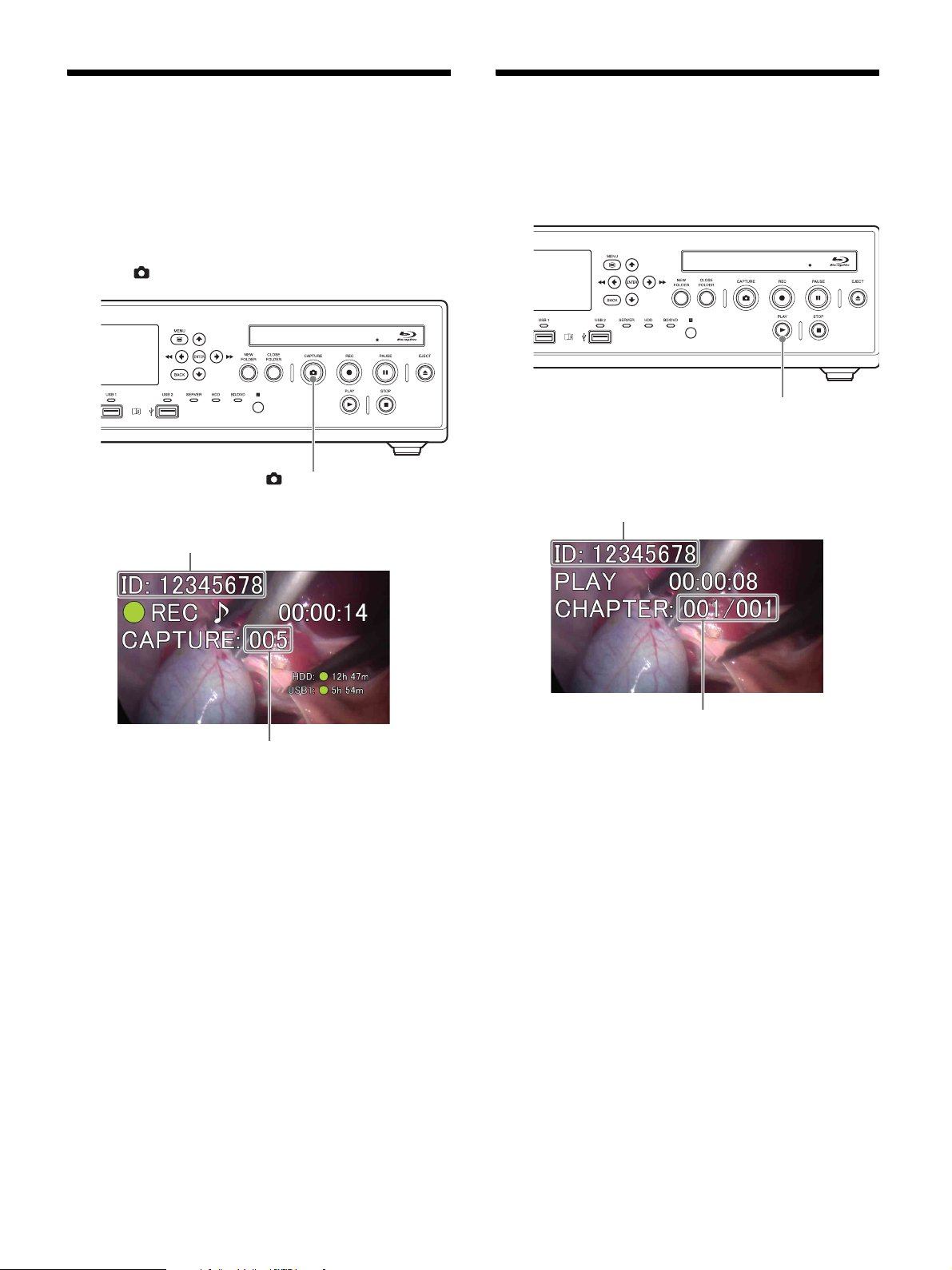
Step 2: Capture Still Images
Step 3: Quick Playback
Play back data recorded in Step 1.
Capture still images from live image transmissions.
Up to 500 still images can be captured for a single
recorded data entry.
Press the CAPTURE button.
CAPTURE button
When you capture an image, the capture number appears.
Patient ID
Press the B PLAY button.
B PLAY button
The most recent recorded data plays back.
“PLAY” and the number of the chapter being played back
appear while playback is in progress.
Patient ID
Capture counter
The still image data is saved.
For details on capturing still images, see “Capture Still
Images” (page 47).
Recorded data entries are created when still images are
captured.
If the surgical procedure or examination is finished and
you want to end the recording session, proceed to “Step
4: End Recording” (page 42) and perform the recording
end operation.
Chapter number
You can also perform the following operations during
playback.
Fast forward playback
Press the M FF button.
Rewind playback
Press the m REW button.
Pause playback
Press the X PAUSE button.
To resume playback, press the X PAUSE button again or
press the B PLAY button.
Stop playback
Press the x STOP button.
41
Page 42
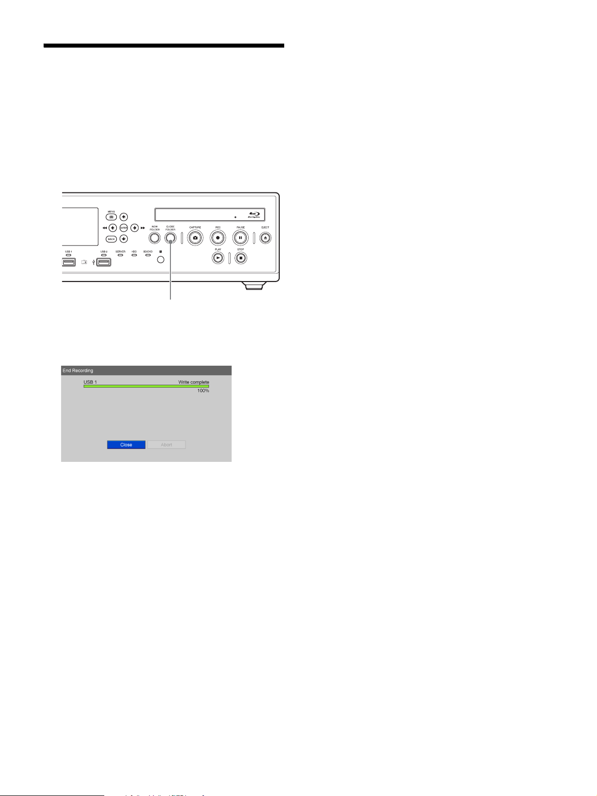
Step 4: End Recording
End the recording session to stop recording to the internal
HDD and stop transfer to external media. This operation
is referred to as “closing a folder.”
1
Press the x STOP button to stop recording.
2
Press the CLOSE FOLDER button.
CLOSE FOLDER button
Select [OK] when the confirmation message appears,
and press the ENTER button to display the [End
Recording] screen.
3
When the writing process is complete, select [Close]
and press the ENTER button.
The [MENU] screen appears again.
42
Page 43
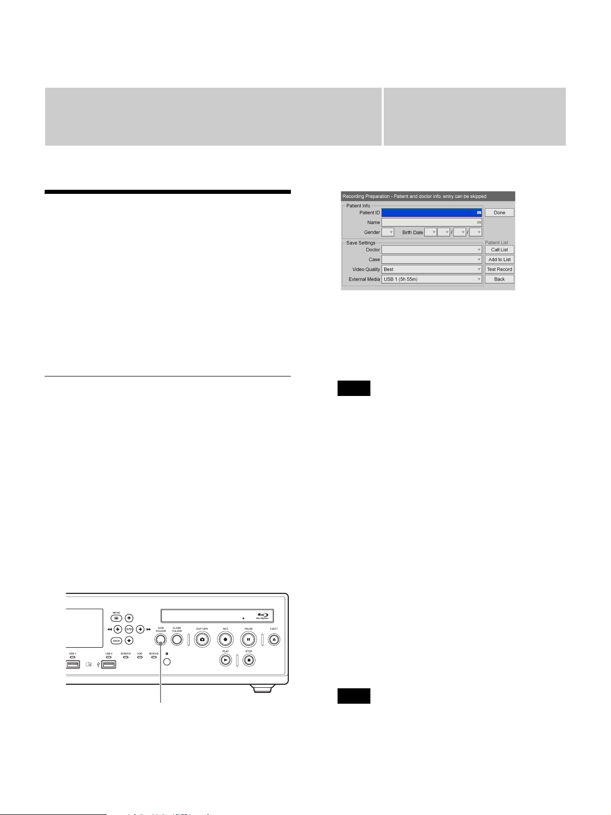
Recording and Playback
Recording Preparation
Before starting to record, enter information regarding the
patient of the surgical procedure or examination,
configure the storage destination and quality settings for
recorded data, and then perform a test recording.
You can also register information for multiple patients in
advance, and simply recall the corresponding patient
information on the day of the procedure or examination.
You can prepare for recording and test record in the
[Recording Preparation] screen.
2
Chapter
Enter patient information.
Patient information entry can be skipped.
[Patient ID]
Enter an identification number for the patient.
4
Patient Information and Data
Storage Settings
Enter information regarding the patient of the surgical
procedure or examination, and configure the storage
destination and quality settings for recorded data.
Use the on-screen keyboard to enter text.
For details on use, see “Using the On-Screen Keyboard
(Text Entry)” (page 26).
1
Press the NEW FOLDER button.
Alternatively, select [Recording Preparation] in the
[MENU] screen, and press the ENTER button.
Tip
Certain symbols (¥ / : ? * " < > | . \) cannot be used for
the patient ID.
[Name]
Enter up to 64 characters in each field of the patient’s
name.
For details on the input fields for the patient name,
see “[Patient Name Field]” (page 59).
[Gender]
Select the gender of the patient.
You can select from [Male], [Female], or [Unknown],
or leave the field empty.
[Birth Date]
Select the year, month, and day.
3
Configure storage settings for recorded data.
[Doctor]
Select the name of the doctor performing the surgical
procedure or examination.
This item can be skipped.
NEW FOLDER button
The [Recording Preparation] screen appears.
Tip
You can register doctors in the [System Admin
Settings] screen – [Edit Doctor List] screen.
43
Page 44
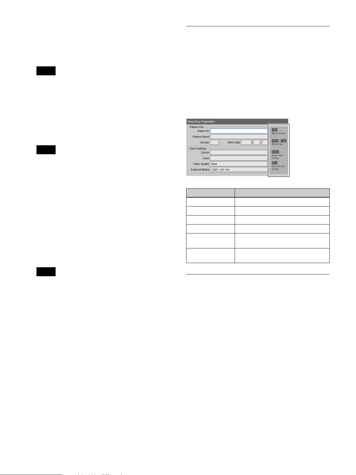
For details on this setting, see “Doctor List
Registration” (page 69).
[Case]
Select the case.
Using a Hard Keyboard for Patient
Information and Data Storage
Settings
Tip
The cases must be registered beforehand.
For details on this setting, see “Registering Cases”
(page 71).
[Video Quality]
Select the video image quality.
You can select form [Best], [High], and [Standard].
This setting applies to both Ch1 and Ch2.
Tip
You can configure a default setting for this item in the
[User Settings] screen – [Quality] tab.
For details on this setting, see “Configuring Image
Quality Settings” (page 31).
[External Media]
When you want to simultaneously save to external
media in addition to saving to the unit’s internal hard
disk, configure these settings to specify the storage
destination for recorded data.
If you do not want to simultaneously record to
external media, select [Not Used].
If you want the unit to detect the inserted media
automatically, select [Auto].
When [Keyboard Mode] is set to [Hard Keyboard] in the
[System Admin Settings] screen – [Device Settings]
screen, you can configure patient information and data
storage settings using only the connected keyboard.
When hard keyboard mode is enabled, a guide appears on
the right side of the screen and the following keys
function as follows.
Key Function
Tab Move to the next input field.
Shift + Tab Move to the previous input field.
R r (arrows) Select items.
T t (arrows) Move within entered text.
Enter Apply the setting, and close the
[Recording Preparation] screen.
Esc Cancel the setting, and close the
[Recording Preparation] screen.
Tips
• If the external media is currently inserted and
recognized, the remaining recording times are also
displayed.
• Servers will not be automatically recognized.
• When auto recognition is enabled and multiple
media are inserted, data will be recorded to the
media in the following order of priority: USB1
BD/DVD
• You cannot change media types in the middle of
recording when auto recognition is enabled.
• Recorded data for Ch2 will be recorded to the same
external media specified for Ch1.
• When [CMS Mode] is set to [Use] in the [System
Admin Settings] screen – [Function Settings]
screen – [CMS] tab, the setting will be fixed at its
current setting.
4
To perform a test recording, proceed to “Test
Recording” (page 45).
If you are finished configuring settings, select [Done]
and press the ENTER button.
t USB2.
t
Registering Multiple Patients in
Advance
You can register information for multiple patients of
procedures and examinations in advance. By doing so,
you can simply select the patient from the registered
patient list on the day of the procedure or examination and
save time on preparation.
To register patients
Register patients for procedures and examinations to the
patient list.
1
Configure patient information and storage settings for
recorded data in the [Recording Preparation] screen,
select [Add to List], and then press the ENTER
button.
For details on patient information and save settings
for recorded data, see “Patient Information and Data
Storage Settings” (page 43).
44
Page 45

The patient is added to the patient list.
1
Select [Call List] in the [Recording Preparation]
screen, and press the ENTER button.
2
Repeat to add any additional patients as necessary.
Tip
You can register up to 100 patients to the patient list.
When you exceed 100, existing patients will be
overwritten automatically starting with the oldest.
To recall patients
Recall patients that have been registered in advance.
1
Select [Call List] in the [Recording Preparation]
screen, and press the ENTER button.
The [Patient List] screen appears.
2
Select the target patient, and press the ENTER button
to select its check box.
3
Select [Execute], and press the ENTER button.
The [Recording Preparation] screen appears again,
and the patient information will be applied in the
[Recording Preparation] screen.
The [Patient List] screen appears.
2
Select the patient to delete, and press the ENTER
button to select its check box.
3
Select [Delete], and press the ENTER button.
4
Select [OK] when the confirmation message appears,
and press the ENTER button.
The patient entry is deleted.
5
Select [Back], and press the ENTER button.
The [Recording Preparation] screen appears again.
Test Recording
Confirm whether images record properly.
When you perform a test recording, images record for 5
seconds and then play back automatically.
1
Select [Test Record] in the [Recording Preparation]
screen, and press the ENTER button.
To edit registered patient settings
Edit patient information and save settings for recorded
data that were registered in advance.
1
Select [Call List] in the [Recording Preparation]
screen, and press the ENTER button.
The [Patient List] screen appears.
2
Select the patient for which you want to edit settings,
and press the ENTER button to select its check box.
3
Select [Change], and press the ENTER button.
The [Change Patient List] screen appears.
4
When you finish editing settings, select [Apply] and
press the ENTER button.
The [Patient List] screen appears again.
5
Select [Execute], and press the ENTER button.
The [Recording Preparation] screen appears again.
2
Select [OK] when the confirmation message appears,
and press the ENTER button.
Recording starts, and a message indicating that test
recording is in progress appears throughout the
process.
After 5 seconds of recording, playback starts
automatically.
When test recording is finished, the [Recording
Preparation] screen appears again.
3
Select [Done], and press the ENTER button.
The [MENU] screen appears again.
To delete registered patients from the list
Delete patients that were registered in advance from the
list.
45
Page 46

Recording
Images can be recorded manually or via contact switch.
This section describes how to record manually.
Tip
You can record up to 24 continuous hours from the
moment you start recording or capture a still image. After
24 hours, recording will stop automatically, and the
“close folder” is performed.
For details on configuring patient information and
storage destinations for recorded data beforehand, see
“Recording Preparation” (page 43).
Tip
For details on how to record via contact switch, contact
your local Sony representative.
Note on the auto delete function for
recorded data
Whenever the remaining capacity on the unit’s internal
hard disk becomes low, an auto delete function
automatically deletes recorded data, starting with the
oldest start dates for recording. This is done to maintain
free space on the unit’s internal hard disk at all times.
To disable the auto delete function, set [Auto Delete] to
[Not Used] in the [System Admin Settings] screen.
Manual Recording
1
Press the z REC button.
Recording starts.
“REC” appears on the front panel display while
recording is in progress.
Recorded data directory
Video data is stored in one of the following directories,
depending on the system administrator settings.
Video data directory
<uppermost folder of the external media>/<recording
start date (year, month, day, hour, minute,
second)_patient ID>/MOVIE/
or
<uppermost folder of the external media>/<patient ID>/
<recording start date (year, month, day, hour, minute,
second)>/MOVIE/
Tips
• The order of the year, month, and day of the recording
date used in the storage directory is based on the date
format of the system settings.
• If the power supply is disconnected before the writing
of the data is complete, the validity of the written data
cannot be guaranteed.
• When recording to external media, the media can be
switched out up to 15 times for a single recorded data
entry. When this limit is exceeded, the “Exch. media
limit exceeded” message appears on the [End
Recording] screen.
• If you press the z REC button again, recording will
start again as a new title for the same patient.
2
Press the x STOP button to stop recording.
3
To end the surgical procedure or examination
recording session, press the CLOSE FOLDER
button.
A confirmation message for ending recording
appears.
4
Select [OK], and press the ENTER button.
The [End Recording] screen appears, and the status of
data transfer to external media, for example, appears.
Wait a moment for the writing process to complete.
5
When the writing process is complete, select [Close]
and press the ENTER button.
To cancel transfer to external media, select [Abort]
and press the ENTER button.
The [MENU] screen appears again.
46
Page 47

Capture Still Images
You can capture a particular shot during a live
transmission, and store it as a still image file.
Still images can be captured manually or via contact
switch. This section describes manual operations.
Tip
For details on contact switch controls, contact your local
Sony representative.
Manual Still Image Capture
To capture a still image, press the CAPTURE button
at the moment you want to capture the still image.
A chapter separator is also created at the position in which
the still image was captured.
Recorded data entries are created when still images are
captured.
If the surgical procedure or examination is finished and
you want to end the recording session, perform the
recording end procedure.
Tip
The order of the year, month, and day of the recording
date used in the storage directory is based on the date
format of the system settings.
For details on use, see “Step 4: End Recording”
(page 42).
Tip
You can configure format setting for still images files in
the [User Settings] screen – [Quality] tab.
For details on this setting, see “Configuring Image
Quality Settings” (page 31).
Still image data directory
Still image data is stored in one of the following
directories, depending on the system administrator
settings.
Still image directory
<uppermost folder of the external media>/<recording
start date (year, month, day, hour, minute,
second)_patient ID>/STILL/
or
<uppermost folder of the external media>/<patient
ID_recording start date (year, month, day, hour, minute,
second)>/STILL/
47
Page 48

Using the Ch1/Ch2 Simultaneous Recording Function
Playback
You can play back the most recent recorded data stored on
the unit’s internal hard disk via simple controls.
This function allows automatic Ch2 recording (2K)
during Ch1 recording (4K).
Tip
In Ch1/Ch2 simultaneous recording mode, the 4K signals
input to Ch2 are downconverted to 2K 1920×1080 format
and recorded while Ch1 recording (4K) is in progress.
Configuring Settings for Ch1/Ch2
Simultaneous Recording
Configure the following settings in the [User Settings]
screen - [Recording] tab.
[Ch1/Ch2 Rec Mode]
Select [Ch1/Ch2 Simul Rec].
[Ch2 Rec Format]
Select 2D or 3D.
For details on the [Recording] tab, see “Configuring
Recording Settings” (page 32).
You can also play back recorded data from search
results. For details, see “Image Search” (page 49).
Playing Back the Most Recent Data
(Quick Playback)
Press the B PLAY button to play back the most recently
recorded data on the internal hard disk.
Tip
Ch1 recorded video data is played back with quick
playback. Recorded data that does not include Ch1 video
will not be played back.
Playback operations
You can use the buttons on the front panel of the unit to
perform the following playback operations.
Fast forward playback
Press the M FF button.
Tip
Tip
When using 2D input signals, 2D mode will be used
regardless of the [Ch2 Rec Format] setting.
Performing Ch1/Ch2 Simultaneous
Recording
Operations for Ch1/Ch2 simultaneous recording are
identical to those for Ch1 recording.
When you press the z REC button, recording for Ch1
starts and triggers recording for Ch2 to start.
Depending on the structure of the data, fast forward
playback may not be possible for the entire recording.
Rewind playback
Press the m REW button.
Pause playback
Press the X PAUSE button.
To resume playback, press the X PAUSE button again or
press the B PLAY button.
Stop playback
Press the x STOP button.
Tips
• If you press the MENU button during playback,
playback will stop.
• When NTSC is selected as the video format under the
system administrator settings, PAL-format recorded
data cannot be played back properly. Conversely, when
PAL is selected, NTSC-format recorded data cannot be
played back properly.
48
Page 49
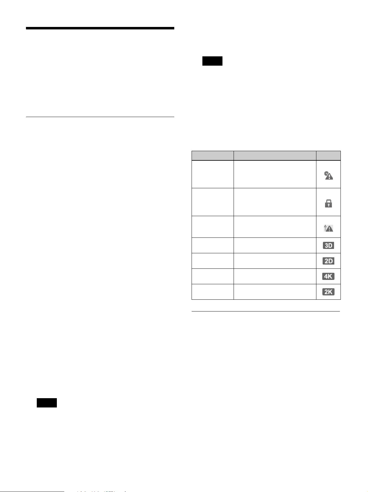
Image Search
[2D/3D]
Select whether the recorded data is 2D data or 3D
data.
You can search for recorded data stored on the unit’s
internal hard disk.
Use the on-screen keyboard to enter text.
For details on use, see “Using the On-Screen Keyboard
(Text Entry)” (page 26).
Specifying Search Conditions
Search for recorded data by specifying conditions such as
patient ID and recording date.
1
Press the MENU button.
The [MENU] screen appears.
2
Select [Recording List], and press the ENTER button.
The [Recording List] screen appears.
3
Select [Search], and press the ENTER button.
The [Search] screen appears.
4
Specify the search conditions, select [Search], and
press the ENTER button.
[Patient ID]
Enter an identification number for the patient.
[Patient Name]
Enter the patient’s name.
[Doctor]
Select the name of the doctor performing the surgical
procedure or examination.
Tip
Select [Clear] and press the ENTER button to clear all
specified search conditions.
5
Select [Search], and press the ENTER button.
A search for recorded data matching the specified
conditions is performed, and the results are displayed.
Status of recorded data
The following icons appear based on the status of the
recorded data.
Status Description Icon
Not saved to
external media
Protected The recorded data is protected
DICOM
transfer failed
3D data The data was recorded in 3D
2D data The data was recorded in 2D
4K data The recorded data is in 4K
2K data The recorded data is in 2K
The recorded data has not been
saved to external media. The
icon disappears when saving is
completed.
and cannot be deleted. The icon
disappears when the protection
is released.
DICOM transfer failed. The icon
disappears when transfer is
successful.
mode.
mode.
format.
format.
Viewing Thumbnails of Recorded
[Recording Date]
Select the year (last two digits), month, and day.
[Status]
Select whether the recorded data has been saved to
external media.
You can select from [Saved to Media], [Not Saved to
Media], or [DICOM Unsent], or leave the field
empty.
Tip
The [DICOM Unsent] setting appears only if
[DICOM] is set to [Use] in the [System Admin
Settings] screen – [DICOM Settings] screen –
[Server] tab.
Data
You can view thumbnail images of recorded data in an
image list.
1
Select [Image List] for the operation box in the
[Recording List] screen.
2
Select the recorded data in the [Recording List]
screen, and press the ENTER button.
The [Image List] screen appears, and thumbnail
images of the recorded data are displayed.
49
Page 50
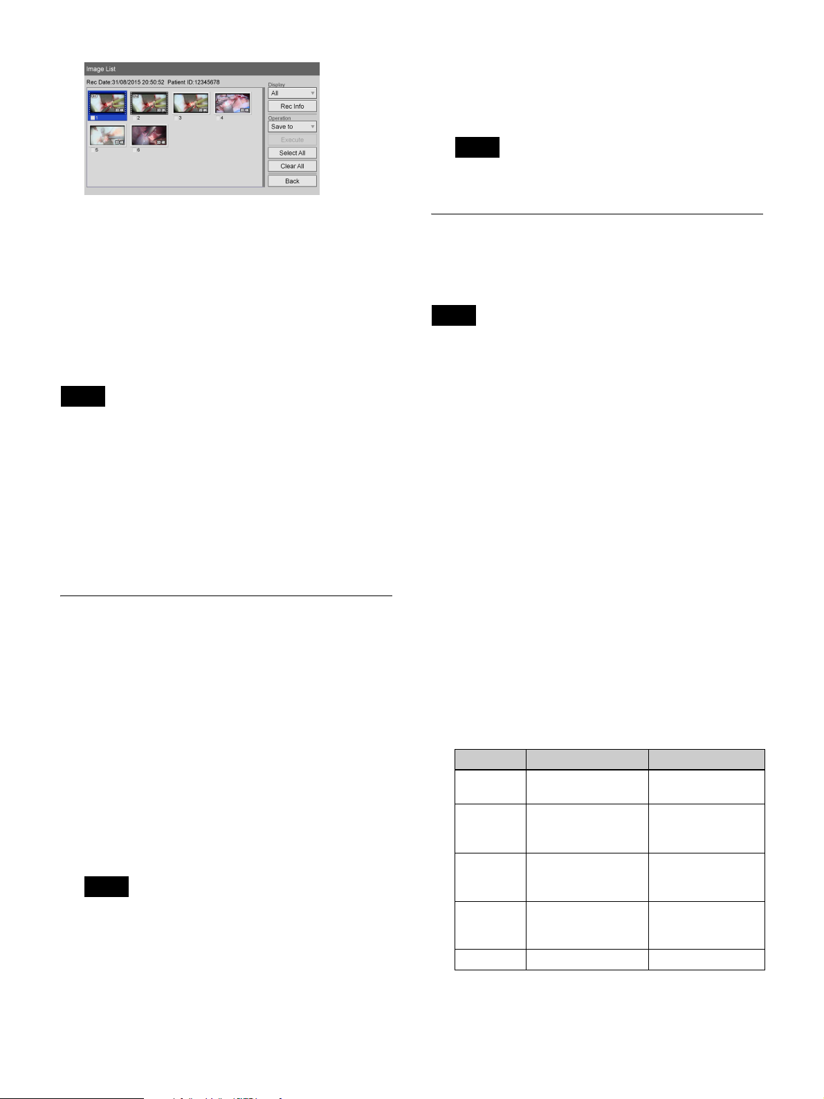
3
To change the type of images for which to display
thumbnails, select the [Display] box and press the
ENTER button.
The [Display] screen appears.
4
Select [Video], [Still], or [All], and press the ENTER
button.
The display changes.
Tips
• If [Video] is selected, the thumbnails are displayed by
title or by chapter, depending on the [Image List
Display] setting in the [System Admin Settings] screen
– [Function Settings] screen – [General 1] tab.
• You can also select recorded data for printing or
copying to external media in the thumbnail display
screen.
For details, see “Processing Recorded Data” (page 51).
4
Select the recorded data you want to play back, and
press the B PLAY button.
The recorded data that is highlighted plays back.
Tip
Only the highlighted recorded data is played back.
Sorting the Recorded Data List
You can sort the recorded data list by recording date,
patient ID, patient name, size, or save status.
Tip
The sizes displayed in the [Recording List] screen
indicate total sizes for Ch1 and Ch2.
1
Select [Sort] in the [Recording List] screen, and press
the ENTER button.
The [Sort] screen appears.
2
Select the [Item] box, and press the ENTER button.
The [Item] screen appears.
3
Select the category by which to sort, and press the
ENTER button.
The [Sort] screen appears again.
Playback from the Search Results
List
1
Select [Image List] for the operation box in the
[Recording List] screen.
2
To play back a title, select the recorded data you want
to play back in the [Recording List] screen (search
results list), and press the B PLAY button.
3
To play back by chapter, select the recorded data you
want to play back, and press the ENTER button.
The [Image List] screen appears, and thumbnail
images of the recorded data are displayed.
Tip
To display recorded data by chapter, set [Image List
Display] to [Chapter] in the [System Admin Settings]
screen – [Function Settings] screen.
4
Select the [Order] box, and press the ENTER button.
The [Order] screen appears.
5
Select [Descending] or [Ascending], and press the
ENTER button.
Depending on the selected category, the descending
and ascending orders are as follows.
Category Descending Ascending
[Recording
Date]
[Patient ID] Alphabetical order
[Patient
Name]
[Status] [Not Saved to
[Size] Start with largest Start with smallest
The [Sort] screen appears again.
Start with newest Start with oldest
t numerical order
Alphabetical order
t numerical order
Media] t [Saved to
Media]
Reverse numerical
order t reverse
alphabetical order
Reverse numerical
order t reverse
alphabetical order
[Saved to Media]
t [Not Saved to
Media]
50
Page 51

6
Select [Execute], and press the ENTER button.
The recorded data is sorted according to the specified
order.
Processing Recorded Data
You can process recorded data stored on the unit’s
internal hard disk in the following ways.
•Printing (page 51)
• Copying to External Media (page 52)
• Editing Patient Information (page 53)
• Protecting Recorded Data (page 54)
• Deleting Recorded Data (page 54)
• Viewing Information on Recorded Data (page 54)
Printing
You can select still images for printing from the
[Recording List] screen.
Tip
For details on configuring the number of images to print
on each sheet and other print settings, see “Configuring
Print Settings” (page 33).
1
Select [Image List] for the operation box in the
[Recording List] screen.
2
Select the recorded data in the [Recording List]
screen, and press the ENTER button.
For details on displaying the [Recording List] screen,
see “Image Search” (page 49).
The [Image List] screen appears.
3
If thumbnail images of video data are displayed,
switch to still image display.
For details on switching the display, see “Viewing
Thumbnails of Recorded Data” (page 49).
4
Select the check boxes for the recorded data you want
to print.
51
Page 52

5
Select the [Operation] box, and press the ENTER
button.
The [Operation] screen appears.
6
Select [Print], and press the ENTER button.
The [Image List] screen appears again.
7
Select [Execute], and press the ENTER button.
The [Print] screen appears.
8
Change the settings as necessary.
If necessary, you can enter a comment of up to 60
characters to be printed with the images.
For details on other settings, see “Configuring Print
Settings” (page 33).
Printing starts.
The remaining amount of paper is displayed during
printing.
Tip
To cancel printing, select [Abort] and press the
ENTER button.
9
When printing is complete, press the ENTER button
while [Close] is selected.
The [Image List] screen appears again.
Copying to External Media
entry. When this limit is exceeded, the “Exch. media
limit exceeded” message appears on the [Save to]
screen.
1
If you are copying to a BD/DVD disc or USB
memory device, insert the media into the unit.
2
Display the [Recording List] screen, select the
operation box, and press the ENTER button.
For details on displaying the [Recording List] screen,
see “Image Search” (page 49).
The [Operation] screen appears.
3
Select [Save to], and press the ENTER button.
The [Recording List] screen appears again.
4
Select the check boxes for the recorded data you want
to copy.
5
Select [Execute], and press the ENTER button.
The [Save to] screen appears.
6
Configure save settings for the recorded data, select
[Execute], and press the ENTER button.
[External Media]
Select the storage destination.
You can select from [BD/DVD], [USB 1], [USB 2],
and [SERVER].
[File Server]
If [SERVER] is selected as the external storage
destination, select a file server (the server configured
for each doctor).
You can copy recorded data stored on the unit’s internal
hard disk onto a BD/DVD disc, USB memory device, or
server.
Recorded data can be copied from the [Recording List]
screen or [Image List] (thumbnail display) screen.
To select data for copying from the
[Recording List] screen
This section describes how to select recorded data for
copying onto external media in the [Recording List]
screen. You can select whether to copy videos, still
images, or both with this procedure.
Tips
• If the power supply is disconnected before the writing
of the data is complete, the validity of the written data
cannot be guaranteed.
• When recording to external media, the media can be
switched out up to 15 times for a single recorded data
[Save Video]
This is enabled when recorded video data is selected.
Select the format of the recorded data you want to
save.
You can select from [Ch1 2D], [Ch1 3D], [Ch2 2D],
and [Ch2 3D]. (Multiple selections can be made.)
All of the check boxes are selected under default
settings.
[Save Still]
Select the check boxes of the storage formats for 3D
still images.
You can select from [3D], [2D], [Convert to 2D
DICOM], [2D Left], [Convert to 2D DICOM Left],
[2D Right], and [Convert to 2D DICOM Right].
(Multiple selections can be made.)
When “convert to DICOM” is selected, the specified
still image format is converted to DICOM before
saving.
All of the check boxes are selected under default
settings.
52
Page 53
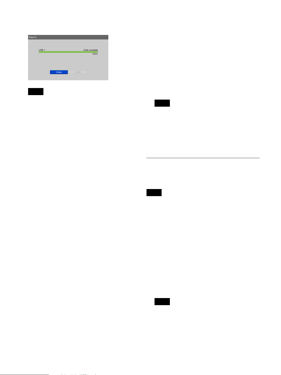
Copying of recorded data starts.
Tip
7
Select [Save to], and press the ENTER button.
The [Image List] screen appears again.
8
Select [Execute], and press the ENTER button.
The [Save to] screen appears.
9
Configure save settings for the recorded data, select
[Execute], and press the ENTER button.
For details on each setting, see step 6 of “To select
data for copying from the [Recording List] screen”
(page 52).
To cancel copying, select [Abort] and press the
ENTER button.
7
When copying is complete, press the ENTER button
while [Close] is selected.
The [Recording List] screen appears again.
To select data for copying from the
[Image List] (thumbnail display) screen
This section describes how to select thumbnail images of
recorded data in the [Image List] screen for copying onto
external media. The copying procedure is identical for
both videos and still images.
1
If you are copying to a BD/DVD disc or USB
memory device, insert the media into the unit.
2
Select [Image List] for the operation box in the
[Recording List] screen.
For details on displaying the [Recording List] screen,
see “Image Search” (page 49).
3
Select the recorded data in the [Recording List]
screen, and press the ENTER button.
The [Image List] screen appears.
Tip
To cancel copying, select [Abort] and press the
ENTER button.
10
When copying is complete, press the ENTER button
while [Close] is selected.
The [Image List] screen appears again.
Editing Patient Information
You can edit the ID, name, and other patient information
that is attached to recorded data and not yet configured.
Note
When [Change Patient Info.] is set [Not Used] in the
[System Admin Settings] screen – [Function Settings]
screen – [Patient Info.] tab, you can only edit patient
information that has not yet been entered. Patient
information entered by a user cannot be edited.
1
Display the [Recording List] screen, select the
operation box, and press the ENTER button.
The [Operation] screen appears.
4
Switch to the thumbnail display for videos when you
want to copy video data, and switch to the thumbnail
display for still images when you want to copy still
image data.
For details on switching the display, see “Viewing
Thumbnails of Recorded Data” (page 49).
5
Select the check boxes for the recorded data you want
to copy.
6
Select the operation box, and press the ENTER
button.
The [Operation] screen appears.
53
2
Select [Change], and press the ENTER button.
The [Recording List] screen appears again.
3
Select the check box of the recorded data for which
you want to edit patient information.
Tip
You can only edit patient information for one
recorded data entry at a time. If multiple recorded
data entries are selected, patient information editing
will be disabled.
4
Select [Execute], and press the ENTER button.
Page 54
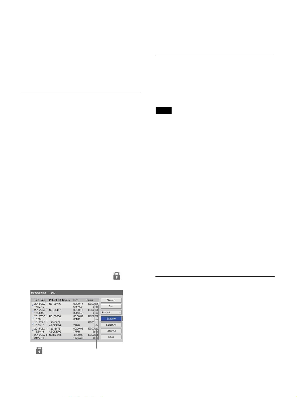
The [Change] screen appears.
5
Edit each item as necessary, select [Change], and
press the ENTER button.
For details on each setting, see “Patient Information
and Data Storage Settings” (page 43).
To remove protection
Select [UnProtect] in step 2 of the previous procedure,
and press the ENTER button. Perform the rest of the
procedure as shown.
Deleting Recorded Data
The patient information is changed, and the
[Recording List] screen appears again.
Protecting Recorded Data
You can protect data to prevent accidental deletion.
Recorded data can be protected or protection can be
removed from the [Recording List] screen.
To select data for protection from the
[Recording List] screen
This section describes how to select recorded data for
protection in the [Recording List] screen. Both videos and
still images will be protected with this procedure.
1
Display the [Recording List] screen, select the
operation box, and press the ENTER button.
For details on displaying the [Recording List] screen,
see “Image Search” (page 49).
The [Operation] screen appears.
You can delete recorded data stored on the unit’s internal
hard disk for particular surgical procedures or
examinations.
Recorded data can be deleted from the [Recording List]
screen.
Note
Recorded data that is deleted cannot be restored.
1
Display the [Recording List] screen, select the
operation box, and press the ENTER button.
For details on displaying the [Recording List] screen,
see “Image Search” (page 49).
The [Operation] screen appears.
2
Select [Delete], and press the ENTER button.
The [Recording List] screen appears again.
3
Select the check boxes for the recorded data you want
to delete.
4
Select [Execute], and press the ENTER button.
2
Select [Protect], and press the ENTER button.
The [Recording List] screen appears again.
3
Select the check boxes for the recorded data you want
to protect.
4
Select [Execute], and press the ENTER button.
The recorded data is protected, and the icon
appears.
The icon appears for recorded data that is protected.
5
Select [OK] when the confirmation message appears,
and press the ENTER button.
When deletion of the recorded data is complete, a
notification message will appear.
To return to the [Recording List] screen, press the
ENTER button.
Viewing Information on Recorded
Data
You can view information on recorded data stored on the
unit’s internal hard disk.
1
Select [Image List] for the operation box in the
[Recording List] screen.
2
Select the check box of the recorded data entry you
want to view in the [Recording List] screen, and press
the ENTER button.
54
Page 55

For details on displaying the [Recording List] screen,
see “Image Search” (page 49).
The [Image List] screen appears.
3
Select [Rec Info], and press the ENTER button.
The information on the recorded data is displayed.
Tip
The sizes displayed in the [Recording List] screen
indicate total sizes for Ch1 and Ch2.
55
Page 56
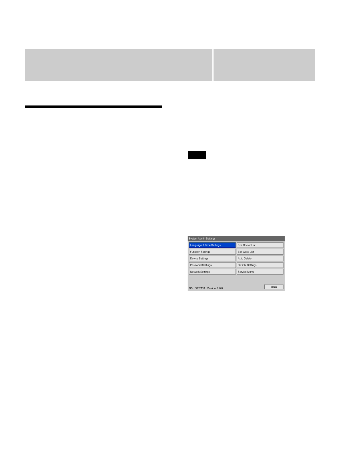
System Administrator
Settings
Displaying the [System Admin Settings] Screen
You can set the initial configurations for various settings
in the [System Admin Settings] screen.
Configurations in the [System Admin Settings] screen
must be performed by the system administrator.
• Language and Time Settings (page 57)
Configure the display language and the date and time
settings.
• Function Settings (page 59)
Configure initial settings for recording and general
functions.
• Device Settings (page 62)
Configure initial settings for connected external
devices.
• Password Settings (page 66)
Register or edit the password for the system
administrator settings.
• Network Settings (page 67)
Configure initial settings for the network and server.
• Doctor List Registration (page 69)
Register and edit information regarding the doctors
performing the surgical procedures and examinations.
• Editing Cases (page 71)
Register or edit entries for surgical procedures and
examinations.
• Auto Delete Settings (page 73)
Configure settings for the auto delete function.
• DICOM Settings (page 73)
Configure DICOM settings.
Use the on-screen keyboard to enter text.
Chapter
2
Select [Settings], and press the ENTER button.
The [Settings] screen appears.
3
Select [System Admin Settings], and press the
ENTER button.
Tip
If password protection is enabled, a password entry
screen will appear.
4
Press the ENTER button when the system
administrator settings notification screen appears.
The [System Admin Settings] screen appears
5
Select the settings you want to configure, and press
the ENTER button.
The setting screen for the selected item appears.
The serial number of the unit and the current software
version appear at the bottom left.
About the [Service Menu]
The [Service Menu] is a function reserved for service
personnel.
It cannot be used by general users.
5
For details on use, see “Using the On-Screen Keyboard
(Text Entry)” (page 26).
1
Press the MENU button.
The [MENU] screen appears.
56
Page 57
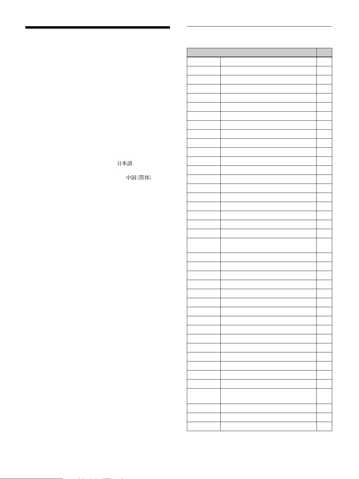
Language and Time
List of time zones
Settings
Configure the display language and the display format for
the current date and time.
1
Select [Language & Time Settings] in the [System
Admin Settings] screen, and press the ENTER
button.
The [Language & Time Settings] screen appears.
2
Configure each setting in the [Language] tab.
[Language]
Select the language for screen displays.
You can select from [English], [ ] (Japanese),
[Deutsch] (German), [Francais] (French), [Italiano]
(Italian), [Espanol] (Spanish), and [ ]
(Simplified Chinese).
[Time Zone]
Select the time zone.
Only the difference from GMT (Greenwich Mean
Time) is displayed for each time zone setting.
For details on time zones, see “List of time zones”
(page 57).
[Use Daylight Saving Time]
Select whether to enable DST (daylight saving time).
The default setting is [Not Used].
3
Configure each setting in the [Date & Time] tab.
[Date Format]
Select the year, month, and day display format.
You can select from [YYYY/MM/DD] (year/month/
day), [MM/DD/YYYY] (month/day/year), and [DD/
MM/YYYY] (day/month/year).
The default setting is [MM/DD/YYYY].
[Date]
Configure the current date.
[Time]
Configure the current time.
4
When you finish configuration, select [Apply] and
press the ENTER button.
The configurations are saved, and the [System Admin
Settings] screen appears again.
Time zone DST
UTC-12:00 International Date Line West
UTC-11:00 Coordinated Universal Time-11
UTC-10:00 Hawaii
UTC-09:00 Alaska a
UTC-08:00 Baja California a
UTC-08:00 Pacific Time (US and Canada) a
UTC-07:00 Arizona
UTC-07:00 Chihuahua, La Paz, Mazatlan a
UTC-07:00 Mountain Time (US and Canada) a
UTC-06:00 Guadalajara, Mexico City, Monterrey a
UTC-06:00 Saskatchewan
UTC-06:00 Central America
UTC-06:00 Central Time (US and Canada) a
UTC-05:00 Indiana (East)
UTC-05:00 Bogota, Lima, Quito, Rio Branco
UTC-05:00 Eastern Time (US and Canada) a
UTC-04:30 Caracas
UTC-04:00 Asuncion a
UTC-04:00 Cuiaba a
UTC-04:00 Santiago
UTC-04:00 Georgetown, La Paz, Manaos, San
UTC-04:00 Atlantic Time (Canada) a
UTC-03:30 Newfoundland a
UTC-03:00 Cayenne, Fortaleza
UTC-03:00 Greenland a
UTC-03:00 Salvador
UTC-03:00 Buenos Aires a
UTC-03:00 Brasilia a
UTC-03:00 Montevideo a
UTC-02:00 Coordinated Universal Time-02 a
UTC-01:00 Azores a
UTC-01:00 Cape Verde Is.
UTC Casablanca
UTC Dublin, Edinburgh, Lisbon, London a
UTC Monrovia, Reykjavik
UTC Coordinated Universal Time
UTC+01:00 Amsterdam, Berlin, Bern, Rome,
UTC+01:00 Windhoek a
UTC+01:00 Sarajevo, Skopje, Warsaw, Zagreb a
UTC+01:00 Brussels, Copenhagen, Madrid, Paris a
Juan
a
Stockholm, Vienna
57
Page 58
Time zone DST
UTC+01:00 Belgrade, Bratislava, Budapest,
a
Ljubljana, Prague
UTC+01:00 West Central Africa
UTC+02:00 Athens, Bucharest a
UTC+02:00 Amman a
UTC+02:00 Istanbul a
UTC+02:00 Jerusalem a
UTC+02:00 Cairo a
UTC+02:00 Kaliningrad (RTZ 1)
UTC+02:00 Damascus a
UTC+02:00 Tripoli
UTC+02:00 Harare, Pretoria
UTC+02:00 Beirut a
UTC+02:00 Helsinki, Kiev, Riga, Skopje, Sofia,
a
Tallinn, Vilnius
UTC+02:00 Eastern Europe a
UTC+03:00 Kuwait, Riyadh
UTC+03:00 Nairobi
UTC+03:00 Baghdad
UTC+03:00 Minsk
UTC+03:00 Moscow, St. Petersburg, Volgograd
a
(RTZ 2)
UTC+03:30 Tehran a
UTC+04:00 Abu Dhabi, Muscat
UTC+04:00 Izhevsk, Samara (RTZ 3)
UTC+04:00 Yerevan a
UTC+04:00 Tblisi
UTC+04:00 Baku a
UTC+04:00 Port Louis a
UTC+04:30 Kabul
UTC+05:00 Ashihabato, Tashkent
UTC+05:00 Islamabad, Karachi a
UTC+05:00 Yekaterinburg (RTZ 4)
UTC+05:30 Sri Jayawardenepura
UTC+05:30 Chennai, Kolkata, Mumbai, New Delhi
UTC+05:45 Kathmandu
UTC+06:00 Astana
UTC+06:00 Dhaka
UTC+06:00 Novosibirsk (RTZ 5) a
UTC+06:30 Yangon (Rangoon)
UTC+07:00 Krasnoyarsk (RTZ 6) a
UTC+07:00 Bangkok, Hanoi, Jakarta
UTC+08:00 Irkutsk (RTZ 7)
UTC+08:00 Ulaanbaatar a
UTC+08:00 Kuala Lumpur, Singapore
UTC+08:00 Perth a
Time zone DST
UTC+08:00 Taipei
UTC+08:00 Beijing, Chongqing, Hong Kong SAR,
Urumqi
UTC+09:00 Seoul
UTC+09:00 Yakutsk (RTZ 8) a
UTC+09:00 Osaka, Sapporo, Tokyo
UTC+09:30 Adelaide a
UTC+09:30 Darwin
UTC+10:00 Vladivostok, Magadan (RTZ 9) a
UTC+10:00 Canberra, Melbourne, Sydney a
UTC+10:00 Guam, Port Moresby
UTC+10:00 Brisbane
UTC+10:00 Hobart a
UTC+10:00 Magadan
UTC+11:00 Solomon Islands, New Caledonia
UTC+11:00 Chokurdakh (RTZ 10)
UTC+12:00 Anadyr, Petropavlovsk-Kamchatsky
(RTZ 11)
UTC+12:00 Auckland, Wellington a
UTC+12:00 Fiji
UTC+12:00 Coordinated Universal Time+12
UTC+13:00 Samoa a
UTC+13:00 Nuku’alofa
UTC+14:00 Christmas Island
58
Page 59

Function Settings
Configure initial settings for patient information, input
signals, and other functions.
1
Select [Function Settings] in the [System Admin
Settings] screen, and press the ENTER button.
[Change Patient Info.]
Select whether to allow changes to patient information at
any time.
The default setting is [Not Used].
[Input Detection] Tab
Configure the detection method for input signals.
The [Function Settings] screen appears.
2
Select a tab, and press the ENTER button.
3
Configure the settings in each tab as necessary.
For details on each tab, see the following.
[Patient Info.] Tab (page 59)
[Input Detection] Tab (page 59)
[Input Signal] Tab (page 59)
[Auto Live] Tab (page 59)
[General 1] Tab (page 60)
[General 2] Tab (page 61)
[Facility] Tab (page 61)
[CMS] Tab (page 61)
4
When you finish configuration, select [Apply] and
press the ENTER button.
The configurations are saved, and the [System Admin
Settings] screen appears again.
[2D/3D]
Select whether to recognize the 2D/3D format of input
signals automatically or whether to specify it manually.
The default setting is [Auto].
[Color Gamut]
Select whether to recognize the color gamut of input
signals automatically or whether to specify it manually.
The default setting is [Auto].
[Input Signal] Tab
Configure initial settings for input signals.
[Region]
You can select from [NTSC] and [PAL].
The default setting is [NTSC].
[I/O Timing]
Select from [Normal] or [Pass-Through] for the input and
output timing.
Select [Normal] as signal processing is usually performed
under normal circumstances. There will be a slight delay
in signal outputs when [Normal] is selected.
Select [Pass-Through] for simultaneous input and output
timing without signal processing.
The default setting is [Normal].
[Patient Info.] Tab
Configure initial settings for patient information.
[Patient ID Length]
Select the number of digits to use for patient IDs.
You can select from 4 to 16 digits.
The default setting is [8].
[Add 0 to Patient ID]
Select whether to add zeros to patient IDs with less than
the specified number of digits.
The default setting is [Use].
[Patient Name Field]
Select the number of display fields to use for the patient
name.
If you select [2] or [3], the patient name field will be
separated into first, middle, and last names.
The default setting is [1].
[Input Detect Duration]
Select from 0 to 3 seconds for the duration for which input
signals are detected.
The default setting is [3 sec].
Note
Image distortion may occur if a duration of 2 seconds or
less is selected.
[3D Line by Line Signal]
When inputting 3D line-by-line signals, select [L First]
(left image) or [R First] (right image) for the first line.
The default setting is [L First].
[Auto Live] Tab
Configure initial settings for the auto live function.
59
Page 60

[Auto Live]
Select whether to use the auto live function.
When the auto live function is enabled and you capture a
still image, the captured image is displayed for the
duration specified with the [Duration] setting of [Auto
Live Settings].
When using the auto live function, you can select the
number of images to display during use ([Single] or
[Multi]).
When [Multi] is selected, three or four captured images
are displayed according to the display position setting.
The default setting is [Not Used].
[Advanced] appears when [Single] or [Multi] is selected.
For details on this setting, see “To configure auto live
settings” (page 60).
3
When you finish configuration, select [Apply] and
press the ENTER button.
The [Auto Live] tab appears again.
[General 1] Tab
Configure initial system settings.
[Show Status]
Select the check box for the status you want to display.
You can select from [Rec Status], [Play Status], and [Idle
Status].
None of the check boxes are selected under default
settings.
Tip
If [Auto Live] is set to [Use] while [I/O Timing] is set to
[Pass-Through], the auto live function will not function.
[Auto Live Still Image]
Displays the type of image that is displayed when a video
is paused while using the auto live function.
This is [Frame] on this unit.
To configure auto live settings
Configure display duration and position settings for the
captured images that are displayed when using the auto
live function.
1
Select [Advanced], and press the ENTER button.
The [Auto Live Settings] screen appears.
2
Configure each setting.
[Duration]
Select the duration for which captured still images are
displayed.
When [Single] is selected, select from 0.5 to 2
seconds for the duration. The default setting is [0.5
sec].
When [Multi] is selected, select from 1 to 5 seconds
for the duration. The default setting is [3 sec].
Tip
If [Show Rec Status] or [Show Idle Status] is set to [Use]
while [I/O Timing] is set to [Pass-Through], the status
information will not be displayed. In addition, status
information will not be updated during the auto live
function.
[Image List Display]
Select the category of thumbnails to display for videos in
the [Image List] screen.
The default setting is [Title].
For details on [Advanced] settings, see “To configure
advanced image list settings” (page 60).
[Auto Eject BD/DVD]
Select whether to automatically eject BD/DVD discs
when they are full.
The default setting is [Not Used].
[Prohibit Remote Control]
Select whether to prohibit control of the unit via the
remote control buttons.
The default setting is [Not Used].
[Menu Display (SDI)]
Select whether to use the output of SDI output connector
D exclusively for displaying menus and other screens.
The default setting is [Not Used].
[Position]
Select from [Top], [Bottom], [Left], and [Right] for
the position in which captured still images are
displayed.
The default setting is [Left].
The four most recent still images are displayed when
[Top] or [Bottom] is selected, and the three most
recent still images are displayed when [Left] or
[Right] is selected.
Tip
If [Menu Display (SDI)] is set to [Use], input images from
SDI output connectors A to D will not be displayed and
black screens will be output instead.
To configure advanced image list settings
Specify the selection state of recorded data when you
perform copy or print operations in the [Image List]
screen.
60
Page 61

1
Select [Advanced] for [Image List Display], and
press the ENTER button.
Use only alphanumeric characters, underscores (_),
hyphens (-), and spaces.
The [Advanced] settings screen appears.
2
Configure each setting, select [Apply] and press the
ENTER button.
[Save to]
Select the selection state of recorded data when [Save
to] is selected in the operation box.
You can select from [Deselect All], [Select All],
[Video], and [Still].
The default setting is [Deselect All].
[Print]
Select the selection state of recorded data when
[Print] is selected in the operation box.
You can select from [Deselect All] and [Still].
The default setting is [Deselect All].
[General 2] Tab
Configure initial system settings.
[Recovery]
Select whether to return to the action that was being
performed when a recovery operation was executed.
The default setting is [Use].
Recovery of recorded data is the only action performed
when [Not Used] is selected.
[Automatic Pause]
Select whether to automatically pause recording when
there is no input signal.
The default setting is [Not Used].
If you select [Use], recording will pause if there is no
input signal for 10 minutes.
[Mic Plug-In Power]
Select the voltage to use when supplying power to the
microphone from the unit.
You can select from [2.5V], [3.2V], and [4.2V].
This item is available when [Mic Plug-In Power] is set to
[Use] in the [User Settings] screen – [Select Input] tab.
The default setting is [2.5V].
[LCD Backlight Adjust]
Select the brightness of the front panel display.
You can select from [25%], [50%], [75%], and [100%].
The default setting is [75%].
[Display Logo]
Select whether to display a logo in the [MENU] screen.
The default setting is [Not Used].
If you want to set [Display Logo] to [Use], be sure to
import the logo.
For details on importing, see “To import a logo”
(page 61).
To import a logo
Import the logo file you want to display.
1
Copy the logo file onto a USB memory device, and
insert the device into a USB port 1 on the front panel
of the unit.
2
Select [Import], and press the ENTER button.
3
Press the ENTER button when the message that
requests media to be inserted appears.
When import of the logo file is complete, a
notification message will appear.
To prepare a logo file
To display a logo, prepare a logo file that can be imported
to the unit and copy it onto a USB memory device
beforehand.
1
Prepare the logo file.
The logo file must meet the following conditions.
File format: 24-bit bitmap
File name: MenuLogo.bmp
Size: 43 (height) × 400 (width) pixels
Background: RGB (102, 102, 102) (gray)
2
Copy the logo file onto a USB memory device.
Create a folder with the following name in the
uppermost directory of the USB memory device, and
copy the logo file.
Folder name: DisplayLogo
[CMS] Tab
[Facility] Tab
Configure initial settings for the facility.
[Facility Name]
Enter up to 32 characters for the facility name.
Configure initial settings for the CMS mode. The CMS
mode is used for transferring recorded data to the content
management system.
[CMS Mode]
Select whether to use the CMS mode.
The default setting is [Not Used].
61
Page 62

Tip
For details on the content management system, contact
your local Sony representative.
Device Settings
Configure settings for external devices.
1
Select [Device Settings] in the [System Admin
Settings] screen, and press the ENTER button.
The [Device] screen appears.
2
Select a tab, and press the ENTER button.
3
Configure the settings in each tab as necessary.
For details on each tab, see the following.
[Device 1] Tab (page 62)
[Device 2] Tab (page 64)
[Control] Tab (page 64)
4
When you finish configuration, select [Apply] and
press the ENTER button.
The configurations are saved, and the [System Admin
Settings] screen appears again.
[Device 1] Tab
Configure settings for the USB devices connected to the
unit.
For details on devices that can be connected to the unit,
contact your local Sony representative.
[USB 3] to [USB 6]
Select the devices connected to USB ports 3 to 6 on the
rear panel of the unit.
The available settings include devices that are compatible
with the unit.
The default setting is [No Device].
If you select a printer, be sure to configure the [Printer
Settings].
For details on this setting, see “To configure printer
settings” (page 63).
Tips
• The unit can recognize the Sony UP-DR80MD printer
automatically. To have the unit recognize UPDR80MD printers automatically, set the USB port to
which the printer will be connected to [No Device] in
the device settings. Be aware that the printer will not be
recognized automatically while recording or playback
62
Page 63

is in progress or while the [Device Settings] screen is
displayed.
• If the USB port to which a card reader is connected is
changed while the unit is turned on, the card reader will
not be recognized. In such cases, restart the unit.
Copy the watermark file onto a USB memory device,
and insert the device into a USB port on the unit.
For details on preparing a watermark file, see “To
prepare a watermark file” (page 63).
If you selected [Bar Code Reader] or [Card Reader], be
sure to configure the [Reader Settings].
For details on this setting, see “To configure reader
settings” (page 64).
If you selected [Touch Panel / Mouse], be sure to
configure the [Touch Panel / Mouse Settings].
For details on this setting, see “Configuring Touch Panel /
Mouse Settings” (page 75).
To configure printer settings
When a UP-DR80MD is selected, configure the color
balance, brightness, and other settings.
1
Select [Advanced] for the USB port to which the UPDR80MD is connected, and press the ENTER button.
[Advanced] appears when one of [USB 3] to [USB 6]
is set to [UP-DR80MD].
The [Printer Settings] screen appears
2
Display the [Color Balance] tab, and adjust the color
balance for cyan, magenta, and yellow and red, green,
and blue.
You can specify a value between –32 to +32 for each
color.
3
Display the [Gray Balance] tab, and adjust the
balance for achromatic colors.
You can specify a value between –50 to +50 for the X
and Y values.
4
Display the [Bright] tab, and configure the
[Sharpness], [Dark], [Gamma], and [Light] settings
to adjust the brightness of printed images.
You can specify a value between –3 to +3 for
[Sharpness], and a value between –32 to +32 for
[Dark], [Gamma], and [Light].
5
Display the [Import] tab, and import a watermark file
or logo file.
[Import Watermark]
Import a watermark file.
When you select [Import Watermark] and press the
ENTER button, a message requesting that you insert
media appears. Select [OK] and press the ENTER
button.
When import of the watermark file is complete, a
notification message will appear.
[Import Logo]
Import a logo file.
Copy the logo file onto a USB memory device, and
insert the device into a USB port on the unit.
For details on preparing a logo file, see “To prepare
a logo file” (page 64).
When you select [Import Logo] and press the ENTER
button, a message requesting that you insert media
appears. Select [OK] and press the ENTER button.
When import of the logo file is complete, a
notification message will appear.
6
When you finish configuration, select [Apply] and
press the ENTER button.
The configurations are saved, and the [Device 1] tab
appears again.
To prepare a watermark file
To print watermarks, prepare a watermark file that can be
imported to the unit and copy it onto a USB memory
device beforehand.
1
Prepare the watermark file.
The watermark file must meet the following
conditions.
• For A4 size paper
File format: 24-bit bitmap
File name: watermark_A4.bmp
Size: 2392 × 3400 pixels
Color:
Background: RGB (255, 255, 255) (white)
Watermark: RGB (0, 0, 0) (black)
• For letter size paper
File format: 24-bit bitmap
File name: watermark_85x11.bmp
Size: 2464 × 3192 pixels
Color:
Background: RGB (255, 255, 255) (white)
Watermark: RGB (0, 0, 0) (black)
63
Page 64

2
Copy the watermark file onto a USB memory device.
Create a folder with the following name in the
uppermost directory of the USB memory device, and
copy the watermark file.
Folder name: Watermark
To prepare a logo file
To print logos, prepare a logo file on the unit and copy it
onto a USB memory device beforehand.
1
Prepare the logo file.
The logo file must meet the following conditions.
File format: 24-bit bitmap
File name: printlogo_UP-DR80MD.bmp
Size: 94 (height) × 900 (width) pixels
2
Copy the logo file onto a USB memory device.
Create a folder with the following name in the
uppermost directory of the USB memory device, and
copy the logo file.
Folder name: PrintLogo
[Birth Date]
Specify the starting position for the date of birth and
the date format.
You can select from [YYYY/MM/DD], [MM/DD/
YYYY], [DD/MM/YYYY], [YYYYMMDD],
[MMDDYYYY], and [DDMMYYYY], or leave the
field empty for the date format.
4
Scan the card.
The data from the card appears in the [Read Data]
area of the [Decode] tab.
Tip
If there is an empty field within the data, an asterisk
(*) appears on the display.
5
Select [Decode], and press the ENTER button.
The decoding results are displayed in the [Decode]
tab.
6
After confirming that the decoding results are correct,
select [Apply] and press the ENTER button.
To configure reader settings
If you selected [Bar Code Reader] or [Card Reader],
configure the settings for reading data. The procedure for
configuring barcode reader and card reader settings is the
same.
1
Select [Advanced] for the USB port to which the
barcode reader or card reader is connected, and press
the ENTER button.
[Advanced] appears when [Bar Code Reader] or
[Card Reader] is selected.
The [Reader Settings] screen appears.
2
Display the [Patient ID/Name] tab, and configure
each setting.
[Patient ID]
Specify the starting position and length for the patient
ID.
[Patient Name]
Specify the starting position and length for the patient
name.
The configurations are saved, and the [Device 1] tab
appears again.
[Device 2] Tab
Configure settings for the printer and keyboard connected
to the unit.
[Printer Used]
Select the printer to be used.
This is fixed at [UP-DR80MD] on this unit.
[Keyboard Mode]
Select whether to use the soft keyboard (i.e., on-screen
keyboard) or a hard keyboard in the [Recording
Preparation] screen.
The default setting is [Soft Keyboard].
You can configure function key settings in [Advanced].
For details, see “Using Function Keys” (page 35).
[Control] Tab
3
Display the [Gender/DOB] tab, and configure each
setting.
[Gender]
Specify the starting position, male, and female for the
gender.
Configure settings related to performing system controls
for the unit and monitor controls from an external device.
[USB 7]
Specify the device connected to USB port 7.
The default setting is [No Device].
If you selected [System Control], you can verify the
transmission speed under [System Control Setting].
64
Page 65

For details on verifying the setting, see “To configure
system control settings” (page 65)
[RS-232C]
Specify the device connected to the RS-232C connector.
The default setting is [No Device].
If you selected [System Control], be sure to configure the
transmission speed under [System Control Setting].
For details on this setting, see “To configure system
control settings” (page 65).
If you selected [Monitor], the monitor’s input will change
as follows.
• When displaying the unit’s menu screens or similar
displays, ports A to C on the monitor will change to SDI
2, even if they were originally set to HDMI.
• When closing the unit’s menu screens or playing back
images, ports A to C on the monitor will change to
HDMI, even if they were originally set to SDI 2.
Tips
• The [Monitor] setting is disabled in touch panel mode.
• [Advanced] appears when [Monitor] is selected.
However, the setting under [System Control Setting]
will be fixed (i.e., the transmission speed will be fixed
at 38400 bps).
[Remote Startup]
Select whether to link the power on/off operations of
remote systems via USB port 7 and the RS-232C
connector.
The default setting is [Do Not Start].
When [USB 7] or [RS-232C] is selected, the remote
system’s on/off operation will be linked to that of the unit
via the selected connector.
The default setting is [9600 bps].
Tip
When [RS-232C] is set to [Monitor], the transmission
speed is fixed at 38400 bps.
The configurations are saved, and the [Control] tab
appears again.
[Contact Switch] Tab
Configure these settings when you want to control the
unit via contact switch devices connected to the contact
switch connectors on the rear panel of the unit.
1
Select the control items for [Contact Switch 1] to
[Contact Switch 3].
Specify what will be controlled via the contact switch
device for each contact switch.
The procedure for configuring [Contact Switch 1] to
[Contact Switch 3] is the same.
The default setting is [Not Used].
[Not Used]
Disable use of the contact switch device.
[Record Video/Pause]
Control pause and resume functions while recording
videos.
[Record Still]
Capture still images.
[Audio On/Off]
Enable or disable audio output.
To configure system control settings
Display or configure the transmission speed when
performing system controls via USB port 7 or the RS232C connector.
1
Select [Advanced] for [USB 7] or [RS-232C], and
press the ENTER button.
[Advanced] appears when [USB 7] or [RS-232C] is
set to [System Control].
The [System Control Setting] screen appears.
2
Select the transmission speed, select [Apply] and
press the ENTER button.
For USB port 7, the transmission speed is fixed at
115200 bps.
For the RS-232C connector, you can select from
9600 bps, 19200 bps, 38400 bps, 57600 bps, and
115200 bps for the transmission speed.
65
[Set Index]
Add an index without saving a still image of the
recording.
2
Select [Advanced] for the contact switch that will
perform the control, and press the ENTER button.
The [Advanced] settings screen appears.
3
Specify the control timing, select [Apply] and press
the ENTER button.
You can select from [Falling Edge], [Leading Edge],
and [State].
The default setting is [Falling Edge].
[State] cannot be selected when the control item is set
to [Record Still] or [Set Index].
Page 66

Tip
The pause control of the [Record Video/Pause]
function will not operate immediately after recording
starts. Wait about 5 seconds before performing the
control.
The [Contact Switch] tab appears again.
Password Settings
Configure password settings to prevent unauthorized
changes to the [System Admin Settings].
When password protection is enabled, a password entry
screen appears when [System Admin Settings] is selected
in the [Settings] screen.
Note
The password is not configured under default conditions.
When configuring the password for the first time,
configure the new password in the [Change Password]
screen without entering an old password. Be sure to write
down the password in case you forget it. The [System
Admin Settings] cannot be accessed without the
password. Guard the password securely to maintain
security.
To enable password protection
1
Select [Password Settings] in the [System Admin
Settings] screen, and press the ENTER button.
The [Password Settings] screen appears.
2
Select the password lock box, and press the ENTER
button.
3
Select [Use], and press the ENTER button.
The default setting is [Not Used].
4
Select [Settings], and press the ENTER button.
The configuration is saved.
To change the password
1
Select [Change] in the [Password Settings] screen,
and press the ENTER button.
The [Change Password] screen appears.
2
Configure each setting, select [Apply] and press the
ENTER button.
[Old Password]
Enter the old password.
66
[New Password]
Enter up to 255 characters for the new password.
Any character that can be entered on the on-screen
keyboard can be used in the password.
Page 67

[Check New Password]
Reenter the new password.
The new password is saved.
Network Settings
Configure initial settings for the network and server.
1
Select [Network Settings] in the [System Admin
Settings] screen, and press the ENTER button.
The [Network Settings] screen appears.
2
Select a tab, and press the ENTER button.
3
Configure the settings in each tab as necessary.
For details on each tab, see the following.
[Network] Tab (page 67)
[IP Address] Tab (page 67)
[DNS Server] Tab (page 68)
[File Server] Tab (page 68)
[Shared] Tab (page 68)
[NTP] Tab (page 68)
4
When you finish configuration, select [Apply] and
press the ENTER button.
The configurations are saved, and the [System Admin
Settings] screen appears again.
[Network] Tab
Configure these settings when using a network.
[Network]
Select whether to use a network.
The default setting is [Not Used].
If you selected [Use], configure the settings in each tab as
necessary.
[IP Address] Tab
[Obtain an IP address automatically]
Select [Use] to use the DHCP to obtain an IP address
automatically, or select [Not Used] to assign a static IP
address manually.
If you selected [Use], the IP address, subnet mask, and
default gateway will be displayed as read-only.
If you selected [Not Used], be sure to configure the [IP
Address], [Subnet Mask], and [Default Gateway]
settings.
67
Page 68

[IP Address]
Enter the IP address.
[Shared] Tab
[Subnet Mask]
Enter the subnet mask.
[Default Gateway]
Enter the IP address for the default gateway.
If you are only using a local network and not connecting
to other networks, do not configure this setting.
[DNS Server] Tab
[Obtain DNS server address automatically]
Select [Use] to obtain the IP address for the DNS server
automatically, or select [Not Used] to specify the IP
address manually.
If you selected [Not Used], be sure to configure the
[Preferred DNS server] and [Alternate DNS server]
settings.
[Preferred DNS server]
Enter the IP address for the preferred DNS server.
If you do not have nor need a preferred DNS server, do
not configure this setting.
[Alternate DNS server]
Enter the IP address for the alternate DNS server.
If you do not have nor need an alternate DNS server, do
not configure this setting.
Configure the necessary settings for using a server as the
storage destination.
[User Name]
Enter a user name.
[Password]
Enter the password.
[NTP] Tab
Configure these settings to obtain the current time from
the NTP server.
[NTP]
Select [Use] to obtain the current time from the NTP
server.
The default setting is [Not Used].
If you selected [Use], be sure to configure the [Address]
and [Port No.] settings.
[Address]
Enter the address for the NTP server.
[Port No.]
Enter the port number.
The default setting is [123].
[File Server] Tab
Configure these settings when specifying a server as the
storage destination for recorded data.
[Server]
Select [Common Setting (Share)] to specify a server as
the storage destination.
The default setting is [Not Used].
If you selected [Common Setting (Share)], be sure to
configure the share name and other settings in the
[Shared] tab.
For details on this setting, see “[Shared] Tab” (page 69).
[Server Name]
Enter the server name.
[Share Name]
Enter the share name.
Use only alphanumeric characters and symbols
(excluding " = / \ [ ] : | < > + ; , ? *).
68
Page 69

Doctor List Registration
Register doctor names and initial settings for each doctor.
The doctor information registered here will be used in the
doctor lists and default settings that appear in other
screens. You can register up to 100 doctors.
Select the external storage media that will be used during
simultaneous recording.
You can select from [Not Specified], [Auto-Detect], [BD/
DVD], [USB 1], [USB 2], and [SERVER].
[File Server] Tab
Configure these settings when specifying a server as the
storage destination.
Registering Doctors
1
Select [Edit Doctor List] in the [System Admin
Settings] screen, and press the ENTER button.
The [Edit Doctor List] screen appears.
2
Select [Add], and press the ENTER button.
The [Add Doctor] screen appears.
3
Select a tab, and press the ENTER button.
4
Configure the settings in each tab as necessary.
For details on each tab, see the following.
[General] Tab (page 69)
[File Server] Tab (page 69)
[Shared] Tab (page 69)
[Print] Tab (page 69)
[External Media] Tab (page 70)
5
When you finish configuration, select [Add] and
press the ENTER button.
The doctor information is added.
[Server]
Select [System Settings] or [Share (CIFS)] for the server
type.
The default setting is [Not Used].
If you selected [Share (CIFS)], be sure to configure the
necessary settings in the [Shared] tab, in addition to the
[Server Name].
For details on this setting, see “[Shared] Tab” (page 69).
[Server Name]
Enter the server name.
[Share Name]
Enter the share name.
Use only alphanumeric characters and symbols
(excluding " = / \ [ ] : | < > + ; , ? *).
[Shared] Tab
Configure the necessary settings for when [Server] is set
to [Share (CIFS)] in the [File Server] tab.
[User Name]
Enter a user name.
[Password]
Enter the password.
[General] Tab
Configure general settings such as the doctor name and
storage destination.
[No.]
Displays the doctor number.
A sequential number is assigned automatically and cannot
be changed.
[Name]
Enter up to 64 characters for the doctor name.
[Video Quality]
Select the video recording quality.
You can select form [Best], [High], and [Standard].
[External Media]
[Print] Tab
[Printer]
Displays the name of the connected printer.
[Layout]
Select the number of still images to print on each sheet.
To use the system settings, select [User Settings].
For the portrait orientation
You can select from 1 image (1 × 1), 2 images (1 × 2), 4
images (2 × 2), 6 images (2 × 3), 8 images (2 × 4), 9
images (3 × 3), 12 images (3 × 4), 15 images (3 × 5), or
18 images (3 × 6).
The default setting is [User Settings].
69
Page 70

For the landscape orientation
You can select from 1 image (1 × 1), 2 images (2 × 1), 4
images (2 × 2), 6 images (3 × 2), 8 images (4 × 2), 9
images (3 × 3), 12 images (4 × 3), 15 images (5 × 3), or
18 images (6 × 3).
The default setting is [User Settings].
[External Media] Tab
Configure save settings for videos and still images.
[Save Video]
Select the check box of the format in which videos will be
saved.
All of the check boxes are selected under default settings.
[Save Still]
Select the check box of the format in which still images
will be saved.
All of the check boxes are selected under default settings.
Editing the Doctor List
1
Select [Edit Doctor List] in the [System Admin
Settings] screen, and press the ENTER button.
The [Edit Doctor List] screen appears.
2
Edit the doctor information.
Sorting the Doctor List (page 70)
Editing Doctor Settings (page 70)
Deleting Doctors (page 71)
3
Select [Settings], and press the ENTER button.
The configurations are saved, and the [System Admin
Settings] screen appears again.
Sorting the Doctor List
1
Select the doctor you want to reposition in the [Edit
Doctor List] screen, select [Up] or [Down], and then
press the ENTER button.
The doctor entry moves up or down one position at a
time.
Editing Doctor Settings
1
Select the doctor for which you want to change
settings in the [Edit Doctor List] screen, select [Edit],
and then press the ENTER button.
The [Edit Doctor] screen appears.
2
After editing the settings, select [Apply] and press the
ENTER button.
The configuration is saved.
For details on each setting, see the following.
[General] Tab (page 69)
[File Server] Tab (page 69)
70
[Shared] Tab (page 69)
[Print] Tab (page 69)
[External Media] Tab (page 70)
Page 71

Note
If you change the doctor name, you will not be able to use
the previous doctor name to search for recorded data
attributed to that name.
Deleting Doctors
1
Select the doctor you want to delete in the [Edit
Doctor List] screen, select [Delete], and then press
the ENTER button.
2
Select [OK] when the confirmation message appears,
and press the ENTER button.
Editing Cases
Edit cases and categories for surgical procedures and
examinations, and create the list of cases that will be used
in the various screens.
1
Select [Edit Case List] in the [System Admin
Settings] screen, and press the ENTER button.
The [Edit Case List] screen appears.
2
Edit the case information.
Registering Cases (page 71)
The doctor entry is deleted.
Deleting Cases (page 71)
Sorting the Case List (page 72)
Editing Case Names (page 72)
Selecting Categories (page 72)
Editing Categories (page 72)
3
Select [Apply] in the [Edit Case List] screen, and
press the ENTER button.
The configurations are saved, and the [System Admin
Settings] screen appears again.
Registering Cases
Up to 100 case entries can be registered for a single
category.
1
Select [Add] in the [Case] area of the [Edit Case List]
screen, and press the ENTER button.
The [Add] screen appears.
2
Enter up to 20 characters for the case name, select
[Add], and then press the ENTER button.
The case is added to the list in the [Edit Case List]
screen.
Deleting Cases
1
Select the case you want to delete in the [Edit Case
List] screen, select [Delete] in the [Case] area, and
then press the ENTER button.
2
Select [OK] when the confirmation message appears,
and press the ENTER button.
71
Page 72

Sorting the Case List
Tip
1
Select the case you want to reposition in the [Edit
Case List] screen, select [Up] or [Down] in the [Case]
area, and then press the ENTER button.
The case entry moves up or down one position at a
time.
Editing Case Names
1
Select the case you want to rename in the [Edit Case
List] screen, select [Edit] in the [Case] area, and then
press the ENTER button.
The [Edit] screen appears.
2
Rename the case, select [Apply], and then press the
ENTER button.
The configurations are saved, and the [Edit Case List]
screen appears again.
Selecting Categories
1
Select the box in the [Category] area of the [Edit Case
List] screen, and press the ENTER button.
Only [Category 1] to [Category 3] can be edited.
Sorting the Category List
1
Select the category you want to reposition in the [Edit
Category List] screen, select [Up] or [Down], and
then press the ENTER button.
The category moves up or down one position at a
time.
Editing Category Names
1
Select the category you want to rename in the [Edit
Category List] screen, select [Edit], and then press the
ENTER button.
The [Edit] screen appears.
2
Rename the category, select [Apply], and then press
the ENTER button.
The configurations are saved, and the [Edit Category
List] screen appears again.
The case category selection screen appears.
2
Select the case category, and press the ENTER
button.
The configurations are saved, and the [Edit Case List]
screen appears again.
Editing Categories
1
Select [Edit] in the [Category] area of the [Edit Case
List] screen, and press the ENTER button.
The [Edit Category List] screen appears.
2
Edit the categories.
Sorting the Category List (page 72)
Editing Category Names (page 72)
3
Select [Apply] in the [Edit Category List] screen, and
press the ENTER button.
The [Edit Case List] screen appears again.
72
Page 73

Auto Delete Settings
DICOM Settings
Select whether to use the auto delete function, and
configure the threshold value that will be used for the
function.
1
Select [Auto Delete] in the [System Admin Settings]
screen, and press the ENTER button.
The [Auto Delete Setting] screen appears.
2
Configure each setting, select [Apply] and press the
ENTER button.
[Auto Delete]
Select whether to use the auto delete function.
The default setting is [Use].
[Auto Delete Value]
Select the threshold value that will be used for the
auto delete function.
You can select from [10%], [20%], and [30%].
The default setting is [10%].
The configuration is saved.
Configure settings that are necessary for DICOM
transmissions of still images.
1
Select [DICOM Settings] in the [System Admin
Settings] screen, and press the ENTER button.
The [DICOM Settings] screen appears.
2
Select a tab, and press the ENTER button.
3
Configure the settings in each tab as necessary.
For details on each tab, see the following.
[Server] Tab (page 73)
[Local Station 1] Tab (page 73)
[Local Station 2] Tab (page 74)
4
When you finish configuration, select [Apply] and
press the ENTER button.
The configurations are saved, and the [System Admin
Settings] screen appears again.
[Server] Tab
Configure these settings when DICOM transmissions will
be performed.
[DICOM]
Select whether to use DICOM.
Select [Use] to perform DICOM transmissions.
The default setting is [Not Used].
[Server Name]
Enter the server name.
Up to 255 characters can be entered.
[Port No.]
Enter the port number.
The default setting is [104].
[AE Title]
Enter the AE title.
Up to 128 characters can be entered.
[Local Station 1] Tab
Enter up to 128 characters for [AE Title], [Station Name],
[Facility Name], and [Facility Address].
73
Page 74

[Local Station 2] Tab
Configure local station settings.
[SOP Class UID]
Select [SC] or [VL] for the SOP Class UID.
The default setting is [SC].
[Character Set]
Select the character set.
You can select from [IR6], [IR13], [IR100], and [IR101].
The default setting is [IR6].
74
Page 75

Touch Panel and Mouse
Chapter
6
Overview
You can connect a commercially available touch panel
monitor or mouse to the unit, and use them to operate the
menu screens.
This chapter describes the settings for using a touch panel
monitor or mouse, and the screens that appear during
touch panel or mouse operations.
Note
If you set one of [USB 3] to [USB 6] to [Touch Panel /
Mouse] in the [System Admin Settings] screen – [Device
Settings] screen – [Device 1] tab in the touch panel /
mouse mode while a compatible device is not connected,
operation will become impossible. Should you
inadvertently disable operation, you can restore the
standard operation mode by performing the following.
1 Connect a hard keyboard.
2 While holding the o key (lower case), press the 1
(on/standby) switch, and release the o key when the
unit turns off.
3 Press the 1 (on/standby) switch to exit standby
mode.
Tips
• The minimum requirement for the touch panel monitor
resolution is 1366 × 768.
• Be aware of the following when setting one of [USB 3]
to [USB 6] to [Touch Panel / Mouse] in the [System
Admin Settings] screen – [Device Settings] screen –
[Device 1] tab.
– You must restart the unit after applying the setting.
– After applying the setting, the
and MENU buttons on the front panel of the unit and
on the infrared remote control unit are disabled.
• For details on supported touch panel monitors, contact
your local Sony representative.
V, v, B, b, ENTER,
Configuring Touch Panel / Mouse Settings
Configure the following settings to enable use of a touch
panel monitor or mouse.
1
Select [Device Settings] in the [System Admin
Settings] screen, and press the ENTER button.
For details on displaying the [System Admin
Settings] screen, see “Displaying the [System Admin
Settings] Screen” (page 56).
The [Device] screen appears.
2
Display the [Device 1] tab, and set the USB port to
which the touch panel monitor or mouse will be
connected ([USB 3] to [USB 6]) to [Touch Panel /
Mouse].
3
Select [Advanced], and press the ENTER button.
The [Touch Panel / Mouse Settings] screen appears.
4
Set [Display Cursor] to [Use], select [Apply], and
then press the ENTER button.
When [Use] is selected, a mouse cursor will appear
on the screen while using touch panel mode or a
mouse.
The default setting is [Not Used].
When you change this setting, a message indicating
that you must restart the unit appears.
5
Connect the touch panel monitor or mouse, and
follow the instructions on the screen and restart the
unit.
75
Page 76
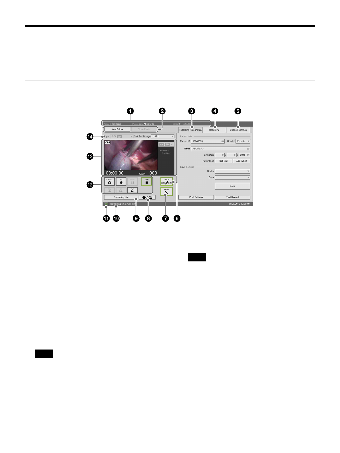
Screen Displays in Touch Panel / Mouse Mode
The screens that appear in touch panel / mouse mode differ slightly from those that appear in standard mode.
This section describes the main differences in the screens and buttons that appear.
[MENU] Screen
a [Patient Info.]
Displays the patient ID, patient name, gender, and
date of birth.
b [New Folder]
Resets the patient information.
[Close Folder]
Use this to end recording, and display the [End
Recording] screen.
c [Recording Preparation] tab
Enter patient information and configure the storage
destination for recorded data before starting to record.
For details on each setting, see “Recording
Preparation” (page 43).
Tip
When entering the date of birth in the touch panel
monitor screen, the year is entered via the on-screen
keyboard.
d [Recording] tab
Allows you to perform recording and playback
controls for Ch2.
For details on each setting, see “Recording
Preparation” (page 43).
Tips
• Ch1 playback cannot be performed during Ch2
recording or playback.
• Ch2 recording or playback cannot be performed
during Ch1 playback.
e [Change Settings] tab
Allows you to change the image quality and video
input.
For details on each setting, see “Configuring Input
Signal Settings” (page 31), “Configuring Image
Quality Settings” (page 31), and “Configuring
Recording Settings” (page 32).
f [Link On] (Ch1/Ch2 link)
Use this to enable Ch1/Ch2 simultaneous recording.
This button is disabled when recording for Ch1 or
Ch2 is in progress.
On (green): Recording and playback controls for
Ch1 and Ch2 are linked.
Off (gray): Ch1 and Ch 2 are not linked.
76
Page 77
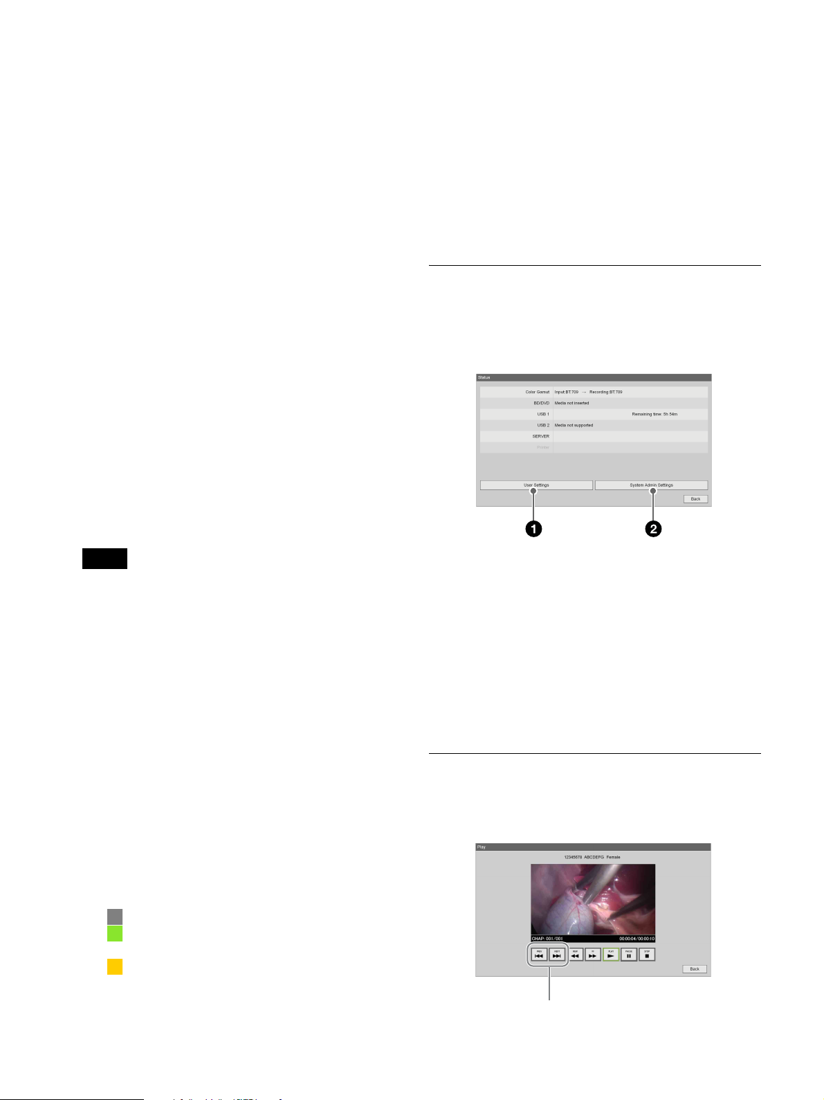
g [AUDIO] (Audio on/off)
Use this to record audio.
On (green): Audio is recorded.
Off (gray): Audio recording is stopped.
h Status button
Displays the “[Status] Screen” (page 77).
n [Input]
This is enabled when [2D/3D] is set to [Manual] in
the [System Admin Settings] screen – [Function
Settings] screen – [Input Detection] tab. When [Auto]
is selected, the input signal is automatically
recognized and displayed here.
This configures the Ch1 input signal.
i [Recording List] button
Displays the [Recording List] screen.
j HDD capacity / error indicator
Displays the internal HDD’s remaining capacity
under normal conditions.
If an error occurs, the error that appears on the front
panel display also appears here.
k 1 (on/standby) button
Use this to set the unit to standby mode.
A confirmation message when you tap this.
l Control buttons
Use these to control playback and recording.
The buttons function identically to the buttons on the
front panel of the unit and on the infrared remote
control unit.
For details, see “Names and Functions of Parts”
(page 18).
Tips
• Ch1 playback cannot be performed during Ch2
recording or playback.
• Ch2 recording or playback cannot be performed
during Ch1 playback.
m Ch1 image display and playback/recording status
Displays the input image or playback image for Ch 1
and various playback/recording status indicators.
Playback/recording counter: Displays the
playback or recording time in “0:00:00” format.
Still capture count: Displays the number of still
images you captured in “CAP:001” format.
Rec mode: Displays the current recording mode.
External media recording status: Displays the
recording status for each external media in
“x <media name> -h -m” format.
Printer status: Displays the print status and the
remaining number of print sheets.
Indicators: The indicators light according to the
status of the corresponding media or printer.
(gray): Operating normally.
(green): Data is being written or printing is in
progress.
(orange): An error has occurred.
[Ch1 Ext Storage]
Configures the external storage destination for Ch1
recorded data.
[Status] Screen
The [Status] screen displays the status of recording to
external media, the conditions of connected devices, and
other status information.
a [User Settings]
Displays the [User Settings] screen.
For details, see “Displaying the [User Settings]
Screen” (page 31).
b [System Admin Settings]
Displays the [System Admin Settings] screen.
For details, see “Displaying the [System Admin
Settings] Screen” (page 56).
Video Playback Screen
This screen appears during video playback.
You can control playback using the buttons at the bottom.
77
Chapter forward/back buttons
Page 78
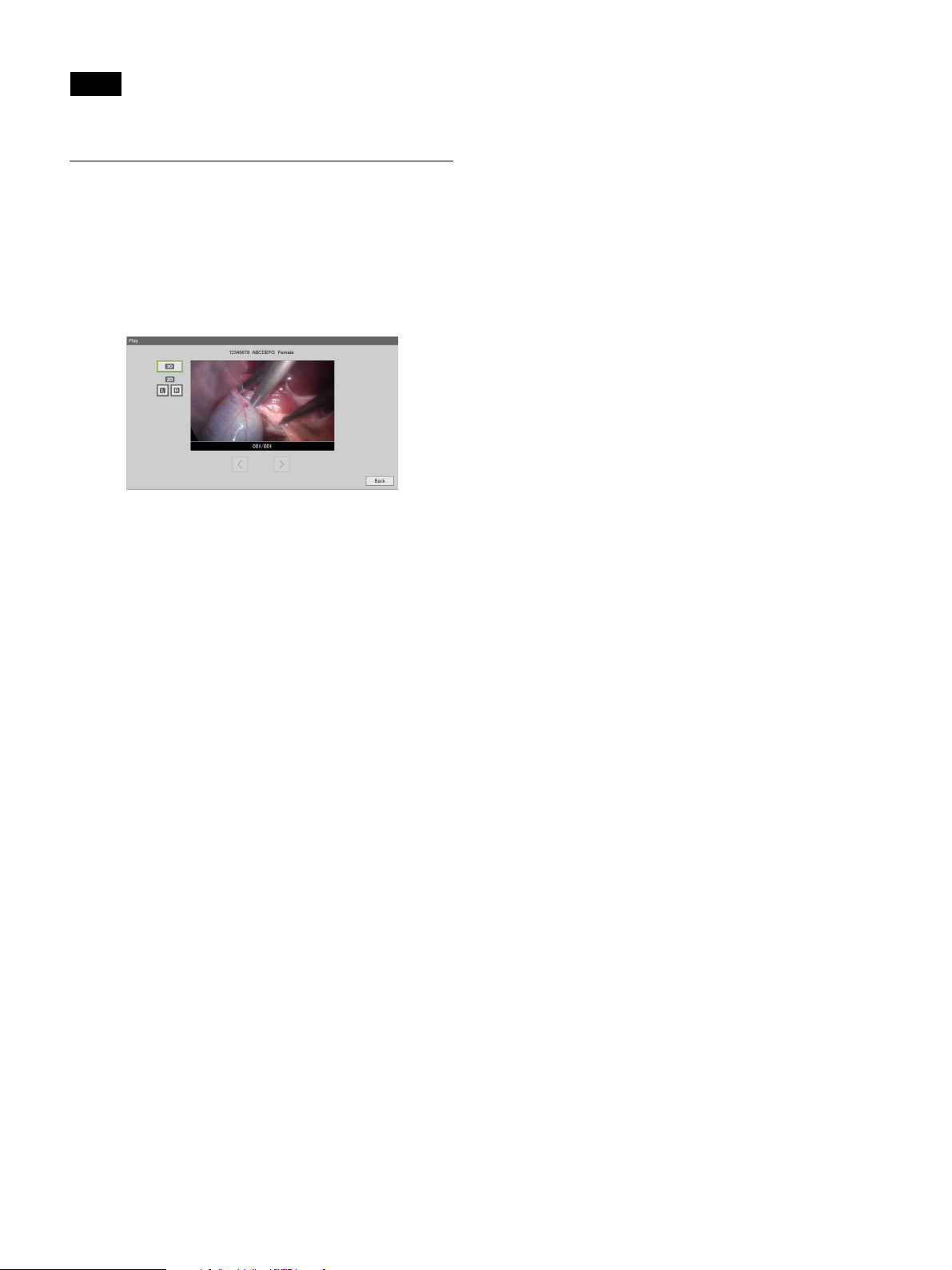
Tip
Ch1 video is played back during quick playback.
Still Image Playback Screen
This screen appears during still image playback.
You can play back the still images in sequence using the
buttons at the bottom.
To play back 3D still images, tap the 3D data button.
To playback the left and right 2D still images, tap the [L]
and [R] buttons.
78
Page 79

Miscellaneous
Chapter
7
Error Messages
When contacting your local Sony representative, please indicate the error message and error ID.
Front panel display Description Solution
Error message Error ID
SYSTEM ERR. 0100 to
0199
SYSTEM ERR. 0200 to
0299
SYSTEM ERR. 0300 to
0399
SYSTEM ERR. 0400 to
0499
SYSTEM ERR. 0500 to
0599
SYSTEM ERR. 0600 to
0699
SYSTEM ERR. 0700 to
0799
SYSTEM ERR. 0800 to
0899
SYSTEM ERR. 0900 to
0999
SYSTEM ERR. 1000 to
1099
SYSTEM ERR. 1101 Activation error Activation failed. Contact your local Sony representative.
SYSTEM ERR. 1102 Update error Firmware update failed. Contact your local Sony
SYSTEM ERR. 1200 to
1299
MAX REC DATA – Limit for recorded data reached The limit for the number of recorded data entries has
MAX CHAPTER – Limit for chapters reached The limit for the number of chapters has been reached.
MAX STILL IMAGE – Limit for still images reached Delete any unnecessary still images.
NO RECORD – No recorded data Recorded data for quick playback does not exist.
HDD LACK – Insufficient space on internal HDD The remaining space on the internal HDD is low. Delete
Motherboard error Restart the unit. (The unit will restart automatically for
Internal HDD error
Database error
Recovery failure
File data error
Capture board error
Optical drive error
Audio device error
Front panel error
Application error
LCD controller error An LCD controller error has occurred. The unit will restart
error ID 0600 to 0699 capture board errors.) If the error
persists, contact your local Sony representative.
representative.
automatically. If the error persists, contact your local
Sony representative.
been reached. Delete any unnecessary recorded data.
Stop the recording operation.
any unnecessary recorded data.
79
Page 80
Front panel display Description Solution
Error message Error ID
HDD FULL – Internal HDD full There is no remaining space on the internal HDD. Delete
any unnecessary recorded data.
KEY INHIBIT – Front panel buttons disabled Button operations on the unit’s front panel are disabled.
WARN. FAN – System/CPU fan warning A fan rotation malfunction has occurred. Contact your
local Sony representative.
WARN. TEMP. – System/CPU temperature warning An internal temperature error has occurred. Check your
operating environment.
WARN. HDD – Internal HDD warning or error An internal HDD error has occurred. Contact your local
Sony representative.
ERR.BATTERY – Battery dead The battery is dead. Contact your local Sony
representative.
WARN.HDD.2 – Corrupted files warning Corrupted files exist on the internal HDD. Perform
recovery on the internal HDD. For details on how to
perform HDD recovery, see “Troubleshooting” (page 81).
If the error persists, contact your local Sony
representative.
WARN.DB1 – Database damaged The database is damaged. Perform recovery on the
database. For details on how to perform database
recovery, see “Troubleshooting” (page 81).
WARN.DB2 –
If the error persists, contact your local Sony
representative.
HDD
RECOVERING
– HDD recovery in progress Internal HDD recovery is in progress. Wait until recovery
is complete.
...
DB1
RECOVERING...
DB2
– Database recovery in progress Database recovery is in progress. Wait until recovery is
complete.
–
RECOVERING...
ERR.HDD – Internal HDD error An internal HDD error has occurred. Contact your local
Sony representative.
ERR.SSD – SSD error Contact your local Sony representative.
WARN LCD – LCD backlight warning The LCD usage time has exceeded 10,000 hours.
Contact your local Sony representative.
PLAYBACK ERR. – Playback failed Perform the playback operation again. If the error
persists, contact your local Sony representative.
80
Page 81

Troubleshooting
Be sure to check the following if a problem occurs. If the
problem persists, contact your local Sony representative.
• “WARN.DB1” or “WARN.DB2” appears on the front
panel display.
tThe database is damaged. Press and hold the BACK button
for at least 5 seconds to perform database recovery.
tIf the warning is displayed even after performing database
recovery, the database cannot be recovered. Contact your
local Sony representative.
• The unit does not turn on when the 1 (on/standby)
switch is pressed.
tThe main power switch on the rear panel of the unit is set to
the a (off) position.
Set the main power switch to the ? (on) position (page 20,
21).
tMake sure that the power cord is properly connected to the
power outlet.
• The buttons on the unit do not function.
Recording, playback, and other operations do not
function properly.
tStatic electricity can have adverse effects on the functioning
of the unit.
Turn off the 1 (on/standby) switch, disconnect the power
cord, and then wait a moment before reconnecting the power
cord and turning on the unit.
• The disc tray does not open when the Z EJECT button
is pressed.
tThe disc tray may take a few seconds to open after you
record data on the disc. This is because the unit is adding
certain required information onto the disc. It is not a
malfunction.
• The unit turns on, but images do not appear or are
distorted.
tMake sure that the cables are properly connected to the input/
output connectors on the rear panel of the unit (page 20).
tMake sure that the cables are not damaged.
• There is no audio, or the audio is noisy.
tMake sure that the cables are properly connected to the input/
output connectors on the rear panel of the unit (page 20).
tMake sure that the cables are not damaged.
tIf the unit is in fast playback or fast reverse playback mode,
press the B PLAY button (page 19).
• The unit cannot record data.
tUse media on which data can be recorded.
tThe remaining storage capacity on the media is insufficient.
Replace the media.
tUse a BD/DVD disc that is compatible with the unit
(page 27).
• The image freezes and audio is cut for brief (about one
second) moments during playback.
tThis unit stops playback between titles, and resumes
playback after about one second. It is not a malfunction.
• Data on the disc is damaged.
tContact your local Sony representative.
• “WARN.HDD.2” appears on the front panel display.
tCorrupted files exist on the internal HDD. Press and hold the
BACK button for at least 5 seconds to perform recovery on
the internal HDD.
tIf the warning is displayed even after performing HDD
recovery, the internal HDD is damaged. Contact your local
Sony representative.
Note
• Do not turn off the unit while internal HDD or database
recovery is in progress. The recovery process will start
after the unit automatically restarts.
• Internal HDD or database recovery can take up to 1
hour each. If recovery does not complete within 1 hour,
the unit will automatically shut down.
81
Page 82

Licenses
•Postgre SQL
• libjpeg
•LibTIFF
•zlib
GNU GENERAL
PUBLIC
DCMTK
This product uses the OFFIS
DICOM Toolkit DCMTK (C) 19932008, OFFIS e.V.
libjpeg
This software is based in part on the
work of the Independent JPEG
Group.
LibTIFF
Copyright (c) 1988-1997 Sam
Leffler
Copyright (c) 1991-1997 Silicon
Graphics, Inc.
Permission to use, copy, modify,
distribute, and sell this software and
its documentation for any purpose is
hereby granted without fee.
zlib
(C) 1995-2004 Jean-loup Gailly and
Mark Adler
GNU GPL/LGPL
Licensed Software
This product includes the following
software licensed under GNU
General Public License (GPL) and
GNU Lesser General Public License
(LGPL) terms.
The attached GPL/LGPL conditions
inform the user about their rights for
procuring, altering, and
redistributing the software source
code.
The source code is provided on the
Web. Access the following URL to
download the code.
http://www.sony.net./Products/
Linux/
Sony will not answer questions
concerning the data in the source
code.
LICENSE
Version 2, June 1991
Copyright (C) 1989, 1991 Free
Software Foundation, Inc., 51
Franklin Street, Fifth Floor, Boston,
MA 02110-1301 USA
Everyone is permitted to copy and
distribute verbatim copies of this
license document, but changing it is
not allowed.
Preamble
The licenses for most software are
designed to take away your freedom to
share and change it. By contrast, the
GNU General Public License is
intended to guarantee your freedom to
share and change free software--to
make sure the software is free for all its
users. This General Public License
applies to most of the Free Software
Foundations software and to any other
program whose authors commit to
using it. (Some other Free Software
Foundation software is covered by the
GNU Lesser General Public License
instead.) You can apply it to your
programs, too.
When we speak of free software, we
are referring to freedom, not price.
Our General Public Licenses are
designed to make sure that you have
the freedom to distribute copies of
free software (and charge for this
service if you wish), that you receive
source code or can get it if you want
it, that you can change the software
or use pieces of it in new free
programs; and that you know you
can do these things.
Package list
•DCMTK
•gSOAP
• Live555 Streaming Media
To protect your rights, we need to
make restrictions that forbid anyone
to deny you these rights or to ask you
to surrender the rights.
82
Page 83

These restrictions translate to certain
responsibilities for you if you
distribute copies of the software, or if
you modify it.
For example, if you distribute copies
of such a program, whether gratis or
for a fee, you must give the recipients
all the rights that you have. You must
make sure that they, too, receive or
can get the source code. And you
must show them these terms so they
know their rights.
We protect your rights with two
steps: (1) copyright the software, and
(2) offer you this license which gives
you legal permission to copy,
distribute and/or modify the
software.
Also, for each author’s protection and
ours, we want to make certain that
everyone understands that there is no
warranty for this free software. If the
software is modified by someone else
and passed on, we want its recipients
to know that what they have is not the
original, so that any problems
introduced by others will not reflect
on the original authors’ reputations.
Finally, any free program is
threatened constantly by software
patents. We wish to avoid the danger
that redistributors of a free program
will individually obtain patent
licenses, in effect making the
program proprietary. To prevent this,
we have made it clear that any patent
must be licensed for everyone’s free
use or not licensed at all.
The precise terms and conditions for
copying, distribution and
modification follow.
TERMS AND
CONDITIONS FOR
COPYING,
DISTRIBUTION AND
MODIFICATION
0. This License applies to any
program or other work which
contains a notice placed by the
copyright holder saying it may
be distributed under the terms of
this General Public License.
The “Program”, below, refers to
any such program or work, and
a “work based on the Program”
means either the Program or any
derivative work under copyright
law: that is to say, a work
containing the Program or a
portion of it, either verbatim or
with modifications and/or
translated into another
language. (Hereinafter,
translation is included without
limitation in the term
“modification”.) Each licensee
is addressed as “you”.
Activities other than copying,
distribution and modification are not
covered by this License; they are
outside its scope. The act of running
the Program is not restricted, and the
output from the Program is covered
only if its contents constitute a work
based on the Program (independent
of having been made by running the
Program).
Whether that is true depends on what
the Program does.
1. You may copy and distribute
verbatim copies of the
Program’s source code as you
receive it, in any medium,
provided that you
conspicuously and
appropriately publish on each
copy an appropriate copyright
notice and disclaimer of
warranty; keep intact all the
notices that refer to this License
and to the absence of any
warranty; and give any other
recipients of the Program a copy
of this License along with the
Program.
You may charge a fee for the
physical act of transferring a copy,
and you may at your option offer
warranty protection in exchange for
a fee.
2. You may modify your copy or
copies of the Program or any
portion of it, thus forming a
work based on the Program, and
copy and distribute such
modifications or work under the
terms of Section 1 above,
provided that you also meet all
of these conditions:
a) You must cause the
modified files to carry
prominent notices stating
that you changed the files
and the date of any change.
b) You must cause any work
that you distribute or
publish, that in whole or in
part contains or is derived
from the Program or any
part thereof, to be licensed
as a whole at no charge to
all third parties under the
terms of this License.
c) If the modified program
normally reads commands
interactively when run, you
must cause it, when started
running for such
interactive use in the most
ordinary way, to print or
display an announcement
including an appropriate
copyright notice and a
notice that there is no
warranty (or else, saying
that you provide a
warranty) and that users
may redistribute the
program under these
conditions, and telling the
user how to view a copy of
this License. (Exception: if
the Program itself is
interactive but does not
normally print such an
announcement, your work
based on the Program is not
required to print an
announcement.)
These requirements apply to the
modified work as a whole. If
identifiable sections of that work are
not derived from the Program, and
can be reasonably considered
independent and separate works in
83
Page 84

themselves, then this License, and its
terms, do not apply to those sections
when you distribute them as separate
works. But when you distribute the
same sections as part of a whole
which is a work based on the
Program, the distribution of the
whole must be on the terms of this
License, whose permissions for other
licensees extend to the entire whole,
and thus to each and every part
regardless of who wrote it.
Thus, it is not the intent of this
section to claim rights or contest
your rights to work written entirely
by you; rather, the intent is to
exercise the right to control the
distribution of derivative or
collective works based on the
Program.
In addition, mere aggregation of
another work not based on the
Program with the Program (or with a
work based on the Program) on a
volume of a storage or distribution
medium does not bring the other
work under the scope of this License.
3. You may copy and distribute the
Program (or a work based on it,
under Section 2) in object code
or executable form under the
terms of Sections 1 and 2 above
provided that you also do one of
the following:
a) Accompany it with the
complete corresponding
machine-readable source
code, which must be
distributed under the terms
of Sections 1 and 2 above
on a medium customarily
used for software
interchange; or,
b) Accompany it with a
written offer, valid for at
least three years, to give
any third party, for a charge
no more than your cost of
physically performing
source distribution, a
complete machinereadable copy of the
corresponding source code,
to be distributed under the
terms of Sections 1 and 2
above on a medium
customarily used for
software interchange; or,
c) Accompany it with the
information you received
as to the offer to distribute
corresponding source code.
(This alternative is allowed
only for noncommercial
distribution and only if you
received the program in
object code or executable
form with such an offer, in
accord with Subsection b
above.)
The source code for a work means
the preferred form of the work for
making modifications to it. For an
executable work, complete source
code means all the source code for all
modules it contains, plus any
associated interface definition files,
plus the scripts used to control
compilation and installation of the
executable. However, as a special
exception, the source code
distributed need not include anything
that is normally distributed (in either
source or binary form) with the
major components (compiler, kernel,
and so on) of the operating system on
which the executable runs, unless
that component itself accompanies
the executable.
If distribution of executable or object
code is made by offering access to
copy from a designated place, then
offering equivalent access to copy
the source code from the same place
counts as distribution of the source
code, even though third parties are
not compelled to copy the source
along with the object code.
4. You may not copy, modify,
sublicense, or distribute the
Program except as expressly
provided under this License.
Any attempt otherwise to copy,
modify, sublicense or distribute
the Program is void, and will
automatically terminate your
rights under this License.
However, parties who have
received copies, or rights, from
you under this License will not
have their licenses terminated
so long as such parties remain in
full compliance.
5. You are not required to accept
this License, since you have not
signed it. However, nothing else
grants you permission to modify
or distribute the Program or its
derivative works. These actions
are prohibited by law if you do
not accept this License.
Therefore, by modifying or
distributing the Program (or any
work based on the Program),
you indicate your acceptance of
this License to do so, and all its
terms and conditions for
copying, distributing or
modifying the Program or
works based on it.
6. Each time you redistribute the
Program (or any work based on
the Program), the recipient
automatically receives a license
from the original licensor to
copy, distribute or modify the
Program subject to these terms
and conditions. You may not
impose any further restrictions
on the recipients’ exercise of the
rights granted herein. You are
not responsible for enforcing
compliance by third parties to
this License.
7. If, as a consequence of a court
judgment or allegation of patent
infringement or for any other
reason (not limited to patent
issues), conditions are imposed
on you (whether by court order,
agreement or otherwise) that
contradict the conditions of this
License, they do not excuse you
from the conditions of this
License. If you cannot distribute
so as to satisfy simultaneously
your obligations under this
License and any other pertinent
obligations, then as a
consequence you may not
distribute the Program at all. For
84
Page 85

example, if a patent license
would not permit royalty-free
redistribution of the Program by
all those who receive copies
directly or indirectly through
you, then the only way you
could satisfy both it and this
License would be to refrain
entirely from distribution of the
Program.
If any portion of this section is held
invalid or unenforceable under any
particular circumstance, the balance
of the section is intended to apply
and the section as a whole is intended
to apply in other
circumstances.
It is not the purpose of this section to
induce you to infringe any patents or
other property right claims or to
contest validity of any such claims;
this section has the sole purpose of
protecting the integrity of the free
software distribution system, which
is implemented by public license
practices. Many people have made
generous contributions to the wide
range of software distributed through
that system in reliance on consistent
application of that system; it is up to
the author/donor to decide if he or
she is willing to distribute software
through any other system and a
licensee cannot impose that choice.
This section is intended to make
thoroughly clear what is believed to
be a consequence of the rest of this
License.
8. If the distribution and/or use of
the Program is restricted in
certain countries either by
patents or by copyrighted
interfaces, the original
copyright holder who places the
Program under this License may
add an explicit geographical
distribution limitation
excluding those countries, so
that distribution is permitted
only in or among countries not
thus excluded. In such case, this
License incorporates the
limitation as if written in the
body of this License.
9. The Free Software Foundation
may publish revised and/or new
versions of the General Public
License from time to time. Such
new versions will be similar in
spirit to the present version, but
may differ in detail to address
new problems or concerns.
Each version is given a
distinguishing version number. If the
Program specifies a version number
of this License which applies to it
and “any later version”, you have the
option of following the terms and
conditions either of that version or of
any later version published by the
Free Software Foundation. If the
Program does not specify a version
number of
this License, you may choose any
version ever published by the Free
Software Foundation.
10. If you wish to incorporate parts
of the Program into other free
programs whose distribution
conditions are different, write to
the author to ask for permission.
For software which is
copyrighted by the Free
Software Foundation, write to
the Free Software Foundation;
we sometimes make exceptions
for this. Our decision will be
guided by the two goals of
preserving the free status of all
derivatives of our free software
and of promoting the sharing
and reuse of software generally.
NO WARRANTY
11. BECAUSE THE PROGRAM
IS LICENSED FREE OF
CHARGE, THERE IS NO
WARRANTY FOR THE
PROGRAM, TO THE
EXTENT PERMITTED BY
APPLICABLE LAW. EXCEPT
WHEN OTHERWISE
STATED IN WRITING THE
COPYRIGHT HOLDERS
AND/OR OTHER PARTIES
PROVIDE THE PROGRAM
“AS IS” WITHOUT
WARRANTY OF ANY KIND,
EITHER EXPRESSED OR
IMPLIED, INCLUDING, BUT
NOT LIMITED TO, THE
IMPLIED WARRANTIES OF
MERCHANTABILITY AND
FITNESS FOR A
PARTICULAR PURPOSE.
THE ENTIRE RISK AS TO
THE QUALITY AND
PERFORMANCE OF THE
PROGRAM IS WITH YOU.
SHOULD THE PROGRAM
PROVE DEFECTIVE, YOU
ASSUME THE COST OF ALL
NECESSARY SERVICING,
REPAIR OR CORRECTION.
12. IN NO EVENT UNLESS
REQUIRED BY
APPLICABLE LAW OR
AGREED TO IN WRITING
WILL ANY COPYRIGHT
HOLDER, OR ANY OTHER
PARTY WHO MAY MODIFY
AND/OR REDISTRIBUTE
THE PROGRAM AS
PERMITTED ABOVE, BE
LIABLE TO YOU FOR
DAMAGES, INCLUDING
ANY GENERAL, SPECIAL,
INCIDENTAL OR
CONSEQUENTIAL
DAMAGES ARISING OUT
OF THE USE OR INABILITY
TO USE THE PROGRAM
(INCLUDING BUT NOT
LIMITED TO LOSS OF DATA
OR DATA BEING
RENDERED INACCURATE
OR LOSSES SUSTAINED BY
YOU OR THIRD PARTIES
OR A FAILURE OF THE
PROGRAM TO OPERATE
WITH ANY OTHER
PROGRAMS), EVEN IF
SUCH HOLDER OR OTHER
PARTY HAS BEEN
ADVISED OF THE
POSSIBILITY OF SUCH
DAMAGES.
85
Page 86

END OF TERMS AND CONDITIONS
How to Apply These
Terms to Your New
You should have received a copy
of the GNU General Public
License along with this program;
if not, write to the Free Software
Foundation, Inc., 51 Franklin
Street, Fifth Floor, Boston, MA
02110-1301 USA.
Also add information on how to
contact you by electronic and paper
mail.
into proprietary programs. If your
program is a subroutine library, you
may consider it more useful to
permit linking proprietary
applications with the library. If this is
what you want to do, use the GNU
Lesser General Public License
instead of this License.
Programs
If you develop a new program, and
you want it to be of the
greatestpossible use to the public, the
best way to achieve this is to make it
free software which everyone can
redistribute and change under these
terms.
To do so, attach the following
notices to the program. It is safest to
attach them to the start of each
source file to most effectively
convey the exclusion of warranty;
and each file should have at least the
“copyright” line and a pointer to
where the full notice is found.
<one line to give the program’s
name and a brief idea of what it
does.>
Copyright (C) <year> <name of
author>
If the program is interactive, make it
output a short notice like this when it
starts in an interactive mode:
Gnomovision version 69,
Copyright (C) year name of
author Gnomovision comes with
ABSOLUTELY NO
WARRANTY; for details type
`show w'.
This is free software, and you are
welcome to redistribute it under
certain conditions; type `show c'
for details.
The hypothetical commands `show
w' and `show c' should show the
appropriate parts of the General
Public License. Of course, the
commands you use may be called
something other than `show w' and
`show c'; they could even be mouseclicks or menu items--whatever suits
your program.
This program is free software;
you can redistribute it and/or
modify it under the terms of the
GNU General Public License as
published by the Free Software
Foundation; either version 2 of
the License, or (at your option)
any later version.
This program is distributed in the
hope that it will be useful, but
WITHOUT ANY
WARRANTY; without even the
implied warranty of
MERCHANTABILITY or
FITNESS FOR A
PARTICULAR PURPOSE. See
the GNU General Public License
for more details.
You should also get your employer
(if you work as a programmer) or
your school, if any, to sign a
“copyright disclaimer” for the
program, if necessary. Here is a
sample; alter the names:
Yoyodyne, Inc., hereby
disclaims all copyright interest
in the program `Gnomovision'
(which makes passes at
compilers) written by James
Hacker.
<signature of Ty Coon>, 1 April
1989
Ty Coon, President of Vice
This General Public License does not
permit incorporating your program
86
Page 87

GNU LESSER GENERAL PUBLIC LICENSE
Version 2.1, February 1999
Copyright (C) 1991, 1999 Free
Software Foundation, Inc. 51
Franklin Street, Fifth Floor, Boston,
MA 02110-1301 USA
Everyone is permitted to copy and
distribute verbatim copies of this
license document, but changing it is
not allowed.
[This is the first released version of
the Lesser GPL. It also counts as the
successor of the GNU Library Public
License, version 2, hence the version
number 2.1.]
Preamble
The licenses for most software are
designed to take away your freedom
to share and change it. By contrast,
the GNU General Public Licenses
are intended to guarantee your
freedom to share and change free
software--to make sure the software
is free for all its users.
This license, the Lesser General
Public License, applies to some
specially designated software
packages--typically libraries--of the
Free Software Foundation and other
authors who decide to use it. You can
use it too, but we suggest you first
think carefully about whether this
license or the ordinary General
Public License is the better strategy
to use in any particular case, based
on the explanations below.
When we speak of free software, we
are referring to freedom of use, not
price. Our General Public Licenses
are designed to make sure that you
have the freedom to distribute copies
of free software (and charge for this
service if you wish); that you receive
source code or can get it if you want
it; that you can change the software
and use pieces of it in new free
programs; and that you are informed
that you can do these things.
To protect your rights, we need to
make restrictions that forbid
distributors to deny you these rights
or to ask you to surrender these
rights. These restrictions translate to
certain responsibilities for you if you
distribute copies of the library or if
you modify it.
For example, if you distribute copies
of the library, whether gratis or for a
fee, you must give the recipients all
the rights that we gave you. You
must make sure that they, too,
receive or can get the source code. If
you link other code with the library,
you must provide complete object
files to the recipients, so that they
can relink them with the library after
making changes to the library and
recompiling it. And you must show
them these terms so they know their
rights.
We protect your rights with a twostep method: (1) we copyright the
library, and (2) we offer you this
license, which gives you legal
permission to copy, distribute and/or
modify the library.
To protect each distributor, we want
to make it very clear that there is no
warranty for the free library. Also, if
the library is modified by someone
else and passed on, the recipients
should know that what they have is
not the original version, so that the
original author’s reputation will not
be affected by problems that might
be introduced by others.
Finally, software patents pose a
constant threat to the existence of
any free program. We wish to make
sure that a company cannot
effectively restrict the users of a free
program by obtaining a restrictive
license from a patent holder.
Therefore, we insist that any patent
license obtained for a version of the
library must be consistent with the
full freedom of use specified in this
license.
Most GNU software, including some
libraries, is covered by the ordinary
GNU General Public License. This
license, the GNU Lesser General
Public License, applies to certain
designated libraries, and is quite
different from the ordinary General
Public License. We use this license
for certain libraries in order to permit
linking those libraries into non-free
programs.
When a program is linked with a
library, whether statically or using a
shared library, the combination of
the two is legally speaking a
combined work, a derivative of the
original library. The ordinary
General Public License therefore
permits such linking only if the
entire combination fits its criteria of
freedom. The Lesser General Public
License permits more lax criteria for
linking other code with
the library.
We call this license the “Lesser”
General Public License because it
does Less to protect the user’s
freedom than the ordinary General
Public License. It also provides other
free software developers Less of an
advantage over competing non-free
programs. These disadvantages are
the reason we use the ordinary
General Public License for many
libraries. However, the Lesser
license provides advantages in
certain special circumstances.
For example, on rare occasions, there
may be a special need to encourage
the widest possible use of a certain
library, so that it becomes a de-facto
standard. To achieve this, non-free
programs must be allowed to use the
library. A more frequent case is that
a free library does the same job as
widely used non-free libraries. In
this case, there is little to gain by
limiting the free library to free
87
Page 88

software only, so we use the Lesser
General Public License.
In other cases, permission to use a
particular library in non-free
programs enables a greater number
of people to use a large body of free
software. For example, permission to
use the GNU C Library in non-free
programs enables many more people
to use the whole GNU operating
system, as well as its variant, the
GNU/Linux operating system.
Although the Lesser General Public
License is Less protective of the
users’ freedom, it does ensure that
the user of a program that is linked
with the Library has the freedom and
the wherewithal to run that program
using a modified version of the
Library.
The precise terms and conditions for
copying, distribution and
modification follow. Pay close
attention to the difference between a
“work based on the library” and a
“work that uses the library”. The
former contains code derived from
the library, whereas the latter must
be combined with the library in order
to run.
TERMS AND
CONDITIONS FOR
COPYING,
DISTRIBUTION AND
MODIFICATION
0. This License Agreement applies
to any software library or other
program which contains a
notice placed by the copyright
holder or other authorized party
saying it may be distributed
under the terms of this Lesser
General Public License (also
called “this License”). Each
licensee is addressed as “you”.
A “library” means a collection of
software functions and/or data
prepared so as to be conveniently
linked with application programs
(which use some of those functions
and data) to form executables.
The “Library”, below, refers to any
such software library or work which
has been distributed under these
terms. A “work based on the
Library” means either the Library or
any derivative work under copyright
law: that is to say, a work containing
the Library or a portion of it, either
verbatim or with modifications and/
or translated straightforwardly into
another language. (Hereinafter,
translation is included without
limitation in the term
“modification”.)
“Source code” for a work means the
preferred form of the work for
making modifications to it. For a
library, complete source code means
all the source code for all modules it
contains, plus any associated
interface definition files, plus the
scripts used to control compilation
and installation of the library.
Activities other than copying,
distribution and modification are not
covered by this License; they are
outside its scope. The act of running
a program using the Library is not
restricted, and output from such a
program is covered only if its
contents constitute a work based on
the Library (independent of the use
of the Library in a tool for writing it).
Whether that is true depends on what
the Library does and what the
program that uses the Library does.
1. You may copy and distribute
verbatim copies of the Library’s
complete source code as you
receive it, in any medium,
provided that you
conspicuously and
appropriately publish on each
copy an appropriate copyright
notice and disclaimer of
warranty; keep intact all the
notices that refer to this License
and to the absence of any
warranty; and distribute a copy
of this License along with the
Library.
You may charge a fee for the
physical act of transferring a copy,
and you may at your option offer
warranty protection in exchange for
a fee.
2. You may modify your copy or
copies of the Library or any
portion of it, thus forming a
work based on the Library, and
copy and distribute such
modifications or work under the
terms of Section 1 above,
provided that you also meet all
of these conditions:
a) The modified work must
itself be a software library.
b) You must cause the files
modified to carry
prominent notices stating
that you changed the files
and the date of any change.
c) You must cause the whole
of the work to be licensed
at no charge to all third
parties under the terms of
this License.
d) If a facility in the modified
Library refers to a function
or a table of data to be
supplied by an application
program that uses the
facility, other than as an
argument passed when the
facility is invoked, then
you must make a good faith
effort to ensure that, in the
event an application does
not supply such function or
table, the facility still
operates, and performs
whatever part of its
purpose remains
meaningful.
(For example, a function in a
library to compute square
roots has a purpose that is
entirely well-defined
independent of the
application. Therefore,
Subsection 2d requires that
any application-supplied
function or table used by this
function must be optional: if
88
Page 89

the application does not
supply it, the square root
function must still compute
square roots.)
These requirements apply to
the modified work as a whole.
If identifiable sections of that
work are not derived from the
Library, and can be
reasonably considered
independent and separate
works in themselves, then this
License, and its terms, do not
apply to those sections when
you distribute them as
separate works. But when you
distribute the same sections
as part of a whole which is a
work based on the Library,
the distribution of the whole
must be on the terms of this
License, whose permissions
for other licensees extend to
the entire whole, and thus to
each and every part
regardless of who wrote it.
Thus, it is not the intent of this
section to claim rights or contest
your rights to work written entirely
by you; rather, the intent is to
exercise the right to control the
distribution of derivative or
collective works based on the
Library.
In addition, mere aggregation of
another work not based on the
Library with the Library (or with a
work based on the Library) on a
volume of a storage or distribution
medium does not bring the other
work under the scope of this License.
3. You may opt to apply the terms
of the ordinary GNU General
Public License instead of this
License to a given copy of the
Library. To do this, you must
alter all the notices that refer to
this License, so that they refer to
the ordinary GNU General
Public License, version 2,
instead of to this License. (If a
newer version than version 2 of
the ordinary GNU General
Public License has appeared,
then you can specify that
version instead if you wish.) Do
not make any other change in
these notices.
Once this change is made in a given
copy, it is irreversible for that copy,
so the ordinary GNU General Public
License applies to all subsequent
copies and derivative works made
from that copy.
This option is useful when you wish
to copy part of the code of the
Library into a program that is not a
library.
4. You may copy and distribute the
Library (or a portion or
derivative of it, under Section 2)
in object code or executable
form under the terms of
Sections 1 and 2 above provided
that you accompany it with the
complete corresponding
machine-readable source code,
which must be distributed under
the terms of Sections 1 and 2
above on a medium customarily
used for software interchange.
If distribution of object code is made
by offering access to copy from a
designated place, then offering
equivalent access to copy the source
code from the same place satisfies
the requirement to distribute the
source code, even though third
parties are not compelled to copy the
source along with the object code.
5. A program that contains no
derivative of any portion of the
Library, but is designed to work
with the Library by being
compiled or linked with it, is
called a “work that uses the
Library”. Such a work, in
isolation, is not a derivative
work of the Library, and
therefore falls outside the scope
of this License.
However, linking a “work that uses
the Library” with the Library creates
an executable that is a derivative of
the Library (because it contains
portions of the Library), rather than a
“work that uses the library”. The
executable is therefore covered by
this License.
Section 6 states terms for distribution
of such executables.
When a “work that uses the Library”
uses material from a header file that
is part of the Library, the object code
for the work may be a derivative
work of the Library even though the
source code is not.
Whether this is true is especially
significant if the work can be linked
without the Library, or if the work is
itself a library. The threshold for this
to be true is not precisely defined by
law.
If such an object file uses only
numerical parameters, data structure
layouts and accessors, and small
macros and small inline functions
(ten lines or less in length), then the
use of the object file is unrestricted,
regardless of whether it is legally a
derivative work. (Executables
containing this object code plus
portions of the Library will still fall
under Section 6.)
Otherwise, if the work is a derivative
of the Library, you may distribute the
object code for the work under the
terms of Section 6.
Any executables containing that
work also fall under Section 6,
whether or not they are linked
directly with the Library itself.
6. As an exception to the Sections
above, you may also combine or
link a “work that uses the
Library” with the Library to
produce a work containing
portions of the Library, and
distribute that work under terms
of your choice, provided that the
terms permit modification of the
work for the customer’s own
use and reverse engineering for
debugging such modifications.
You must give prominent notice with
each copy of the work that the
89
Page 90

Library is used in it and that the
Library and its use are covered by
this License. You must supply a copy
of this License. If the work during
execution displays copyright notices,
you must include the copyright
notice for the Library among them,
as well as a reference directing the
user to the copy of this License.
Also, you must do one of these
things:
a) Accompany the work with
the complete
corresponding machinereadable source code for
the Library including
whatever changes were
used in the work (which
must be distributed under
Sections 1 and 2 above);
and, if the work is an
executable linked with the
Library, with the complete
machine-readable “work
that uses the Library”, as
object code and/or source
code, so that the user can
modify the Library and
then relink to produce a
modified executable
containing the modified
Library. (It is understood
that the user who changes
the contents of definitions
files in the Library will not
necessarily be able to
recompile the application
to use the modified
definitions.)
b) Use a suitable shared
library mechanism for
linking with the Library. A
suitable mechanism is one
that (1) uses at run time a
copy of the library already
present on the user’s
computer system, rather
than copying library
functions into the
executable, and (2) will
operate properly with a
modified version of the
library, if the user installs
one, as long as the
modified version is
interface-compatible with
the version that the work
was made with.
c) Accompany the work with
a written offer, valid for at
least three years, to give the
same user the materials
specified in Subsection 6a,
above, for a charge no
more than the cost of
performing this
distribution.
d) If distribution of the work
is made by offering access
to copy from a designated
place, offer equivalent
access to copy the above
specified materials from
the same place.
e) Verify that the user has
already received a copy of
these materials or that you
have already sent this user
a copy.
For an executable, the required form
of the “work that uses the Library”
must include any data and utility
programs needed for reproducing the
executable from it. However, as a
special exception,
the materials to be distributed need
not include anything that is normally
distributed (in either source or binary
form) with the major components
(compiler, kernel, and so on) of the
operating system on which the
executable runs, unless that
component itself accompanies the
executable.
It may happen that this requirement
contradicts the license restrictions of
other proprietary libraries that do not
normally accompany the operating
system. Such a contradiction means
you cannot use both them and the
Library together in an executable
that you distribute.
7. You may place library facilities
that are a work based on the
Library side-by-side in a single
library together with other
library facilities not covered by
this License, and distribute such
a combined library, provided
that the separate distribution of
the work based on the Library
and of the other library facilities
is otherwise permitted, and
provided that you do these two
things:
a) Accompany the combined
library with a copy of the
same work based on the
Library, uncombined with
any other library facilities.
This must be distributed
under the terms of the
Sections above.
b) Give prominent notice with
the combined library of the
fact that part of it is a work
based on the Library, and
explaining where to find
the accompanying
uncombined form of the
same work.
8. You may not copy, modify,
sublicense, link with, or
distribute the Library except as
expressly provided under this
License. Any attempt otherwise
to copy, modify, sublicense,
link with, or distribute the
Library is void, and will
automatically terminate your
rights under this License.
However, parties who have
received copies, or rights, from
you under this License will not
have their licenses terminated
so long as such parties remain in
full compliance.
9. You are not required to accept
this License, since you have not
signed it. However, nothing else
grants you permission to modify
or distribute the Library or its
derivative works. These actions
are prohibited by law if you do
not accept this License.
Therefore, by modifying or
distributing the Library (or any
work based on the Library), you
indicate your acceptance of this
License to do so, and all its
terms and conditions for
copying, distributing or
modifying the Library or works
based on it.
90
Page 91

10. Each time you redistribute the
Library (or any work based on
the Library), the recipient
automatically receives a license
from the original licensor to
copy, distribute, link with or
modify the Library subject to
these terms and conditions. You
may not impose any further
restrictions on the recipients’
exercise of the rights granted
herein. You are not responsible
for enforcing compliance by
third parties with this License.
11. If, as a consequence of a court
judgment or allegation of patent
infringement or for any other
reason (not limited to patent
issues), conditions are imposed
on you (whether by court order,
agreement or otherwise) that
contradict the conditions of this
License, they do not excuse you
from the conditions of this
License. If you cannot distribute
so as to satisfy simultaneously
your obligations under this
License and any other pertinent
obligations, then as a
consequence you may not
distribute the Library at all. For
example, if a patent license
would not permit royalty-free
redistribution of the Library by
all those who receive copies
directly or indirectly through
you, then the only way you
could satisfy both it and this
License would be to refrain
entirely from distribution of the
Library.
If any portion of this section is held
invalid or unenforceable under any
particular circumstance, the balance
of the section is intended to apply,
and the section as a whole is intended
to apply in other circumstances.
It is not the purpose of this section to
induce you to infringe any patents or
other property right claims or to
contest validity of any such claims;
this section has the sole purpose of
protecting the integrity of the free
software distribution system which
is implemented by public license
practices. Many people have made
generous contributions to the wide
range of software distributed through
that system in reliance on consistent
application of that system; it is up to
the author/donor to decide if he or
she is willing to distribute software
through any other system and a
licensee cannot impose that choice.
This section is intended to make
thoroughly clear what is believed to
be a consequence of the rest of this
License.
12. If the distribution and/or use of
the Library is restricted in
certain countries either by
patents or by copyrighted
interfaces, the original
copyright holder who places the
Library under this License may
add an explicit geographical
distribution limitation
excluding those countries, so
that distribution is permitted
only in or among countries not
thus excluded. In such case, this
License incorporates the
limitation as if written in the
body of this License.
13. The Free Software Foundation
may publish revised and/or new
versions of the Lesser General
Public License from time to
time. Such new versions will be
similar in spirit to the present
version, but may differ in detail
to address new problems or
concerns.
Each version is given a
distinguishing version number. If the
Library specifies a version number
of this License which applies to it
and “any later version”, you have the
option of following the terms and
conditions either of that version or of
any later version published by the
Free Software Foundation. If the
Library does not specify a license
version number, you may choose any
version ever published by the Free
Software Foundation.
14. If you wish to incorporate parts
of the Library into other free
programs whose distribution
conditions are incompatible
with these, write to the author to
ask for permission. For software
which is copyrighted by the
Free Software Foundation,
write to the Free Software
Foundation; we sometimes
make exceptions for this. Our
decision will be guided by the
two goals of preserving the free
status of all derivatives of our
free software and of promoting
the sharing and reuse of
software generally.
NO WARRANTY
15. BECAUSE THE LIBRARY IS
LICENSED FREE OF
CHARGE, THERE IS NO
WARRANTY FOR THE
LIBRARY, TO THE EXTENT
PERMITTED BY
APPLICABLE LAW. EXCEPT
WHEN OTHERWISE
STATED IN WRITING THE
COPYRIGHT HOLDERS
AND/OR OTHER PARTIES
PROVIDE THE LIBRARY
“AS IS” WITHOUT
WARRANTY OF ANY KIND,
EITHER EXPRESSED OR
IMPLIED, INCLUDING, BUT
NOT LIMITED TO, THE
IMPLIED WARRANTIES OF
MERCHANTABILITY AND
FITNESS FOR A
PARTICULAR PURPOSE.
THE ENTIRE RISK AS TO
THE QUALITY AND
PERFORMANCE OF THE
LIBRARY IS WITH YOU.
SHOULD THE LIBRARY
PROVE DEFECTIVE, YOU
ASSUME THE COST OF ALL
NECESSARY SERVICING,
REPAIR OR CORRECTION.
16. IN NO EVENT UNLESS
REQUIRED BY
APPLICABLE LAW OR
AGREED TO IN WRITING
WILL ANY COPYRIGHT
HOLDER, OR ANY OTHER
91
Page 92

PARTY WHO MAY MODIFY
AND/OR REDISTRIBUTE
THE LIBRARY AS
PERMITTED ABOVE, BE
LIABLE TO YOU FOR
DAMAGES, INCLUDING
ANY GENERAL, SPECIAL,
INCIDENTAL OR
CONSEQUENTIAL
DAMAGES ARISING OUT
OF THE USE OR INABILITY
TO USE THE LIBRARY
(INCLUDING BUT NOT
LIMITED TO LOSS OF DATA
OR DATA BEING
RENDERED INACCURATE
OR LOSSES SUSTAINED BY
YOU OR THIRD PARTIES
OR A FAILURE OF THE
LIBRARY TO OPERATE
WITH ANY OTHER
SOFTWARE), EVEN IF SUCH
HOLDER OR OTHER PARTY
HAS BEEN ADVISED OF
THE POSSIBILITY OF SUCH
DAMAGES.
END OF TERMS AND CONDITIONS
How to Apply These
Terms to Your New
Libraries
If you develop a new library, and you
want it to be of the greatest possible
use to the public, we recommend
making it free software that everyone
can redistribute and change. You can
do so by permitting redistribution
under these terms (or, alternatively,
under the terms of the ordinary
General Public License).
To apply these terms, attach the
following notices to the library. It is
safest to attach them to the start of
each source file to most effectively
convey the exclusion of warranty;
and each file should have at least the
“copyright” line and a pointer to
where the full notice is found.
<one line to give the library’s
name and a brief idea of what
it does.>
Copyright (C) <year> <name
of author>
Public License for more
details.
You should have received a
copy of the GNU Lesser
General Public License along
with this library; if not, write
to the Free Software
Foundation, Inc., 51 Franklin
Street, Fifth Floor, Boston,
MA 02110-1301 USA
Also add information on how to
contact you by electronic and paper
mail.
You should also get your employer
(if you work as a programmer) or
your school, if any, to sign a
“copyright disclaimer” for the
library, if necessary. Here is a
sample; alter the names:
Yoyodyne, Inc., hereby
disclaims all copyright
interest in the library `Frob' (a
library for tweaking knobs)
written by James Random
Hacker.
<signature of Ty Coon>, 1
April 1990
Ty Coon, President of Vice
That’s all there is to it!
This library is free software;
you can redistribute it and/or
modify it under the terms of
the GNU Lesser General
Public License as published
by the Free Software
Foundation; either version
2.1 of the License, or (at your
option) any later version.
This library is distributed in
the hope that it will be useful,
but WITHOUT ANY
WARRANTY; without even
the implied warranty of
MERCHANTABILITY or
FITNESS FOR A
PARTICULAR PURPOSE.
See the GNU Lesser General
92
Page 93

Specifications
Recording Features
Recording Video Format
MPEG-4 AVC/H.264
Recording Audio Format
LPCM, AAC LC
Recording File Format
XAVC S, MP4
Recording Media
Internal HDD (4TB)
External USB Storage
Network (CIFS)
DVD-R
BD-R/BD-R DL
BD-RE/BD-RE DL
Input Resolution
4096 × 2160
3840 × 2160
Recording Resolution
3840 × 2160
1920 × 1080
Recording Bit Rate (4K)
150 Mbps (Best)
100 Mbps (High)
60 Mbps (Standard)
Recording Bit Rate (HD)
24 Mbps (Best)
18 Mbps (High)
12 Mbps (Standard)
Connectors
Input Connectors
3G-SDI (BNC type) (4)
AUDIO (Stereo mini jack) (1)
MIC (Stereo mini jack) (1)
AC Inlet (3-pin) (1)
Output Connectors
3G-SDI (BNC type) (4)
HDMI (Type A) (1)
AUDIO (Stereo mini jack) (1)
Other Interfaces
USB 3.0 (Type A) (2)
USB 2.0 (Type A) (4)
USB 2.0 (Type B) (1)
Network (RJ-45, 1000 Base-T/100 Base) (1)
REMOTE RS-232C (D-sub 9-pin) (1)
REMOTE contact switch (stereo mini jack) (4)
Equipotential
General
Power Requirements
100 V to 240 V AC, 50/60 Hz
Input Current
1.25 A to 0.52 A
Operating Temperature
5°C to 40°C (41°F to 104°F)
Operating Humidity
20% to 80% (Maximum wet-bulb temperature: 30 °C
(86 °F)) (no condensation)
Operating Pressure
700 hPa to 1,060 hPa
Storage and Transport Temperature
–20°C to +60°C (–4°F to +140°F)
Storage and Transport Humidity
20% to 90% (Maximum wet-bulb temperature: 30 °C
(86 °F)) (no condensation)
Storage and Transport Pressure
700 hPa to 1,060 hPa
Mass
Approx. 6.5 kg (Approx. 14 lb. 5.3 oz.)
Dimensions
305.0 × 329.0 × 115.5 mm (12
(W × D × H) (including longest protrusions)
Supplied Items
Before Using this Unit (1)
Instructions for Use (1)
CD-ROM (Instructions for Use, PROTOCOL
MANUAL) (1)
Warranty booklet (1)
Service Contact List (1)
Infrared remote control unit (RM-M010) (1)
European Representative (1)
Separately-Sold Accessories
Foot Switch (FS-24)
Caution
The FS-24 has an Ingress Protection rating of IPx3.
Therefore, do not operate it environments exposed to
splashing liquids (e.g., surgical operating rooms). For
safety, use a device with a rating of IPx6 or higher when
operating in such environments.
REMOTE contact switch connectors
Connector specifications (stereo mini jack)
1
/8 × 13 × 4 5/8 in.)
3
2
1
1GND
2 TRIGGER SIGNAL (TTL)
If the status changes for at least 100 msec, the action
configured in the REMOTE contact switch settings will
start.
3 BUSY STATUS (TTL)
HIGH level will be initiated according to the REMOTE
contact switch settings.
Design and specifications are subject to change without
notice.
93
Page 94

Medical Specifications
Protection against electric shock:
Class I
Protection against harmful ingress of water:
Ordinary
Degree of safety in the presence of a flammable
anesthetic mixture with air or with oxygen or
nitrous oxide:
Not suitable for use in the presence of a flammable
anesthetic mixture with air or with oxygen or
nitrous oxide
Mode of operation:
Continuous
Notes
• Always make a test recording, and verify that it was
recorded successfully.
SONY WILL NOT BE LIABLE FOR DAMAGES
OF ANY KIND INCLUDING, BUT NOT
LIMITED TO, COMPENSATION OR
REIMBURSEMENT ON ACCOUNT OF
FAILURE OF THIS UNIT OR ITS RECORDING
MEDIA, EXTERNAL STORAGE SYSTEMS OR
ANY OTHER MEDIA OR STORAGE SYSTEMS
TO RECORD CONTENT OF ANY TYPE.
• Always verify that the unit is operating properly
before use. SONY WILL NOT BE LIABLE FOR
DAMAGES OF ANY KIND INCLUDING, BUT
NOT LIMITED TO, COMPENSATION OR
REIMBURSEMENT ON ACCOUNT OF THE
LOSS OF PRESENT OR PROSPECTIVE PROFITS
DUE TO FAILURE OF THIS UNIT, EITHER
DURING THE WARRANTY PERIOD OR AFTER
EXPIRATION OF THE WARRANTY, OR FOR
ANY OTHER REASON WHATSOEVER.
• SONY WILL NOT BE LIABLE FOR CLAIMS OF
ANY KIND MADE BY USERS OF THIS UNIT OR
MADE BY THIRD PARTIES.
• SONY WILL NOT BE LIABLE FOR THE LOSS,
REPAIR, OR REPRODUCTION OF ANY DATA
RECORDED ON THE INTERNAL STORAGE
SYSTEM, RECORDING MEDIA, EXTERNAL
STORAGE SYSTEMS OR ANY OTHER MEDIA
OR STORAGE SYSTEMS.
• SONY WILL NOT BE LIABLE FOR THE
TERMINATION OR DISCONTINUATION OF
ANY SERVICES RELATED TO THIS UNIT
THAT MAY RESULT DUE TO
CIRCUMSTANCES OF ANY KIND.
94
Page 95

Index
Numerics
4K Convert Modes 37
A
Auto delete function 46, 73
[Auto Live] tab 59
Auto live 60
B
BD/DVD indicator 19
C
Capturing still images 41, 47
Ch1/Ch2 simultaneous recording 48
Close folder 42
[CMS] tab 61
Compatible discs 27
[Contact Switch] tab 65
Contact switches 65
[Control] tab 64
Copying 52
D
Deleting data 54
[Device 1] tab 62
[Device 2] tab 64
Device settings 62
DICOM settings 73
[DNS Server] tab 68
E
Editing cases 71
Editing categories 72
Editing the case list 71
Editing the doctor list 70
[End Recording] screen 42
Error messages 79
External media 44
F
[Facility] tab 61
[File Server] tab 68, 69
File servers 68, 69
Front panel 18
Function keys 35
Function settings 59
G
[General] tab 69
[General 1] tab 60
[General 2] tab 61
H
Hard keyboards 44
HDD indicator 19
I
Image list 49, 50
Image quality settings 31
Image search 49
[Input Detection] tab 59
[Input Signal] tab 59
Input signal settings 31
Input signals 31
[IP Address] tab 67
K
Keyboard mode 44
L
Language and time settings 57
[Local Station 1] tab 73
[Local Station 2] tab 74
Logos 61, 64
M
Mouse 75
N
[Network] tab 67
Network settings 67
[NTP] tab 68
O
On/standby switch 29
On-Screen Keyboard 26
P
Password settings 66
Patient ID 59
[Patient Info.] tab 59
Patient Information 53
Playback 48
[Print] tab 69
Print settings 33
Printer settings 63
Printing 51
Protecting data 54
Q
Quick playback 41, 48
R
Reader settings 64
Rear panel 20
Recording 40, 46
Recording list 49, 50
Recording preparation 43
Registering doctors 69
Registering patients 44
Remote control unit 22
Removing protection 54
S
Save settings 32
[Server] tab 73
SERVER indicator 19
[Shared] tab 68, 69
Status displays 24
Still image capture 47
Still image directory 47
System administrator settings 56
System control settings 65
T
Test recording 45
Thumbnail display 49
Touch panel and monitor 75
Troubleshooting 81
U
USB indicators 19
User settings 31
V
Video data directory 46
W
Watermark files 63
Watermarks 34
95
Page 96

Sony Corporation
1-7-1 Konan, Minato-ku, Tokyo,
108-0075 Japan
 Loading...