

Page 1
Flash
Operating Instructions
Mode d’emploi
Bedienungsanleitung
Istruzioni per l’uso
Gebruiksaanwijzing
2-687-455-13 (1)
HVL-F56AM
© 2006 Sony Corporation Printed in Japan
Page 2

English
Before operating the product, please read this manual thoroughly and
retain it for future reference.
WARNING
To reduce fire or shock hazard, do not expose the unit to rain or moisture.
Tape over lithium battery contacts to avoid short-circuit when disposing of
batteries, and follow local regulations for battery disposal.
Keep batteries or things that could be swallowed away from young
children. Contact a doctor immediately if an object is swallowed.
Immediately remove the batteries and discontinue use if...
• the product is dropped or subjected to an impact in which the interior is
exposed.
• the product emits a strange smell, heat, or smoke.
Do not disassemble. Electric shock may occur if a high voltage circuit
inside the product is touched.
IMPORTANT SAFETY
INSTRUCTIONS
When using your photographic equipment, basic safety
precautions should always be followed, including the
following:
Read and understand all instructions before using.
Close supervision is necessary when any appliance is used
by or near children. Do not leave appliance unattended
while in use.
Care must be taken as burns can occur from touching hot
parts.
2
Page 3

Do not operate appliance with a damaged cord or if the
appliance has been dropped or damaged- until it has been
examined by a qualified serviceman.
Let appliance cool completely before putting away. Loop
cord loosely around appliance when storing.
To reduce the risk of electric shock, do not immerse this
appliance in water or other liquids.
To reduce the risk of electric shock, do not disassemble this
appliance, but take it to a qualified serviceman when
service or repair work is required. Incorrect reassembly can
cause electric shock when the appliance is used
subsequently.
The use of an accessory attachment not recommended by
the manufacturer may cause a risk of fire, electric shock, or
injury to persons.
Batteries may become hot or explode due to improper use.
Use only the batteries specified in this instruction manual.
Do not install the batteries with the polarity (+/-) reversed.
Do not subject batteries to fire or high temperatures.
Do not attempt to recharge (except for rechargeable
batteries), short or disassemble.
Do not mix, batteries of different types, brands or ages.
SAVE THESE
INSTRUCTIONS
CAUTION
Do not touch the flashtube during operation, it may become hot
when the flash fires.
3
Page 4

For customers in Europe
Disposal of Old Electrical & Electronic Equipment
(Applicable in the European Union and other European
countries with separate collection systems)
This symbol on the product or on its packaging indicates that
this product shall not be treated as household waste. Instead
it shall be handed over to the applicable collection point for
the recycling of electrical and electronic equipment. By
ensuring this product is disposed of correctly, you will help
prevent potential negative consequences for the environment
and human health, which could otherwise be caused by
inappropriate waste handling of this product. The recycling
of materials will help to conserve natural resources. For more
detailed information about recycling of this product, please
contact your local Civic Office, your household waste
disposal service or the shop where you purchased the
product.
For the customers in the U.S.A.
CAUTION
You are cautioned that any changes or modifications not expressly
approved in this manual could void your authority to operate this
equipment.
NOTE:
This equipment has been tested and found to comply with the limits for a
Class B digital device, pursuant to Part 15 of the FCC Rules.
These limits are designed to provide reasonable protection against harmful
interference in a residential installation.
This equipment generates, uses, and can radiate radio frequency energy
and, if not installed and used in accordance with the instructions, may
cause harmful interference to radio communications.
However, there is no guarantee that interference will not occur a particular
installation. If this equipment does cause harmful interference to radio or
television reception, which can be determined by turning the equipment
off and on, the user is encouraged to try to correct the interference by one
or more of following measures:
– Reorient or relocate the receiving antenna.
– Increase the separation between the equipment and receiver.
– Connect the equipment into an outlet on a circuit different from that to
which the receiver is connected.
– Consult the dealer or an experienced radio/TV technician for help.
4
Page 5

Table of contents
Features .................................... 6
Name of parts ..........................7
Control panel ........................... 8
Data panel ................................9
Preparations
Inserting batteries ................. 10
Attachment and removal
of the flash ............................. 12
Auto power ON/OFF .......... 13
Basics
Program auto flash
(The basics) ............................ 14
Recording modes .................. 17
Apprications
Zoom flash coverage ............ 19
Test-flash/Modeling flash ... 22
Bounce flash .......................... 24
Close-up photography
(downward bounce) .............27
Data panel illuminator .........28
AF illuminator ....................... 29
Mode and select buttons ......30
Manual flash (M) .................. 32
High-speed sync (HSS) ........ 35
Wireless flash mode (WL).... 37
Connecting camera and flash
by cable...................................43
Setting power level (LEVEL)
................................................. 44
Multiple flash (MULTI)........46
Reset to default settings .......51
Custom setting ...................... 52
Additional
Information
Accessories.............................55
Notes on use .......................... 57
Maintenance .......................... 58
Specifications .........................59
5
Page 6

Before use
For details, refer to the operating instructions supplied with your camera.
This flash is not dust-proof, splash-proof or waterproof.
Do not place this flash in the following locations
Regardless of whether this unit is in use or in storage, do not place it in any
of the following locations. Doing so may lead to a malfunction.
• Placing this flash in locations subject to direct sunlight such as on
dashboards or near a heater may cause this unit to deform or
malfunction.
• Locations with excessive vibration
• Locations with strong electromagnetism
• Locations with excessive sand
In locations such as the seashore and other sandy areas or where dust
clouds occur, protect the unit from sand and dust.
This may lead to a malfunction.
Features
• The HVL-F56AM is a compact, clip-on flash that provides a large flash
output with a guide number 56 (85 mm position, ISO 100 · m).
• The built-in wide panel expands flash coverage to a focal length of 17
mm.
• The HVL-F56AM assures highly reliable ADI (Advanced Distance
Integration) flash metering when used in combination with compatible
lenses.
• The HVL-F56AM supports wireless high-speed sync photography.
• The flash head tilts 90° upward, 180° left and 90° right to bounce flash
(with lock function) and 10° downward for close-up photography.
* This function may not be available on some camera models.
6
Page 7
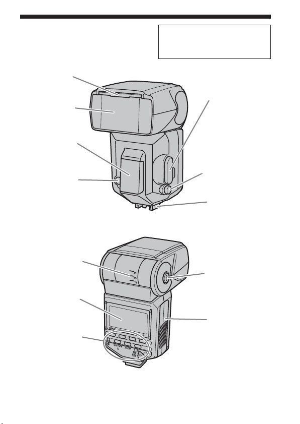
Name of parts
Built-in wide panel
(21)
Flashtube
Inside terminal
• Accessory terminal (43)
• External-power terminal (56)
Terminal cap
AF illuminator
(29)
Wireless controlsignal receiver (37)
Bounce indicator
(24)
Data panel (9)
Control panel (8)
Mounting-footrelease button (12)
Mounting foot
Bounce lockrelease button (24)
Battery-chamber
door (10)
Remove the protective sheet from the front
of the AF illuminator before use.
7
Page 8
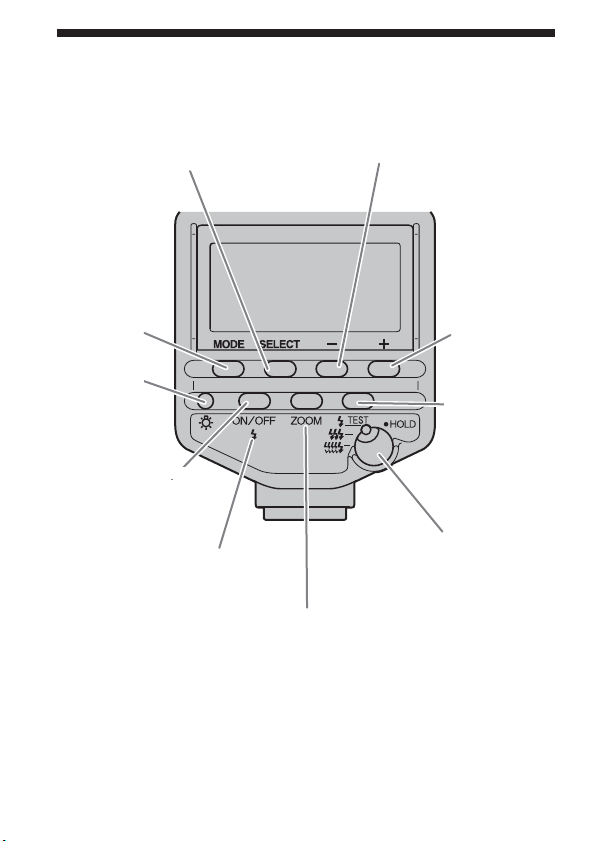
Control panel
SELECT button
MODE button
Data-panel
illuminator
(28)
Flash ON/OFF button
(13)
Flash-ready lamp (15)
– button
+ button
Test-flash
button/
Modeling-flash
button (23)
Test-flash mode
selection/Hold switch
(22)
ZOOM (flash-coverage)
selection button (20)
8
Page 9
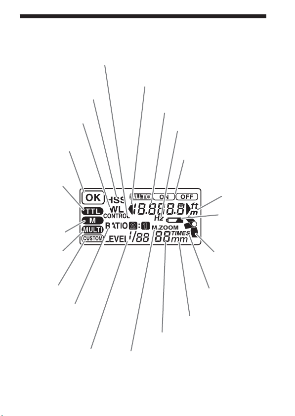
Data panel
Wireless controller indicator*
High-speed-sync
indicator (35)
Wireless flash
indicator (40-42)
Flash-OK indicator
(15)
TTL indicator (32)
Manual-flashcontrol
indicator (32)
Multiple-flash
indicator (46)
Custom
indicator (52)
Ratio-flash indicator*
* This indicator is
displayed, but this
function is not
available.
Power-level
indicator (44)
Flash-range-warning indicators (16)
Flash-range (16)/Multiple-flashfrequency display (47)
Hz indicator (47)
Flash ON/OFF indicators
(14)
ft/m indicator
(53)
Low-battery
indicator (11)
Bounce
indicator (24)
TIMES indicator
(48)
mm indicator (19)
Zoom (19, 20)/Multiple-flashrepetition display (48)
Manual-ZOOM
indicator (20)
On this page, all indicators are displayed for explanatory purposes.
9
Page 10
Inserting batteries
The HVL-F56AM may be powered by :
*Batteries are not supplied.
• Four AA-size alkaline batteries
• Four AA-size lithium batteries
• Four AA-size rechargeable nickel-metal hydride (Ni-MH) batteries
Always ensure that rechargeable nickel-metal hydride batteries are
charged in the specified charger unit.
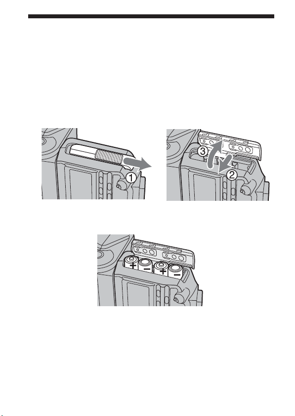
1 Open the battery-chamber door as shown.
2 Insert the batteries in the battery chamber as in the
diagram.
3 Close the battery-chamber door.
• Follow the reverse steps when opening the battery-chamber door.
• The indicator appears on the data panel. If it does not appear, press
the flash ON/OFF button.
10
Page 11
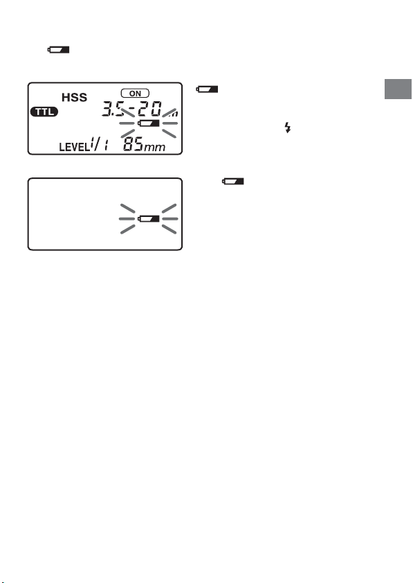
Checking Batteries
The indicator on the data panel blinks when the batteries are low.
blinking
Changing the batteries is
recommended. The flash can still be
used in this state if (Flash-ready
lamp) on the rear of the unit is lit.
Only blinking
Flash cannot be used.
Insert new batteries.
• If nothing appears when the flash ON/OFF button is pressed, check the
orientation of the batteries.
Preparations
11
Page 12
Attachment and removal of the
flash
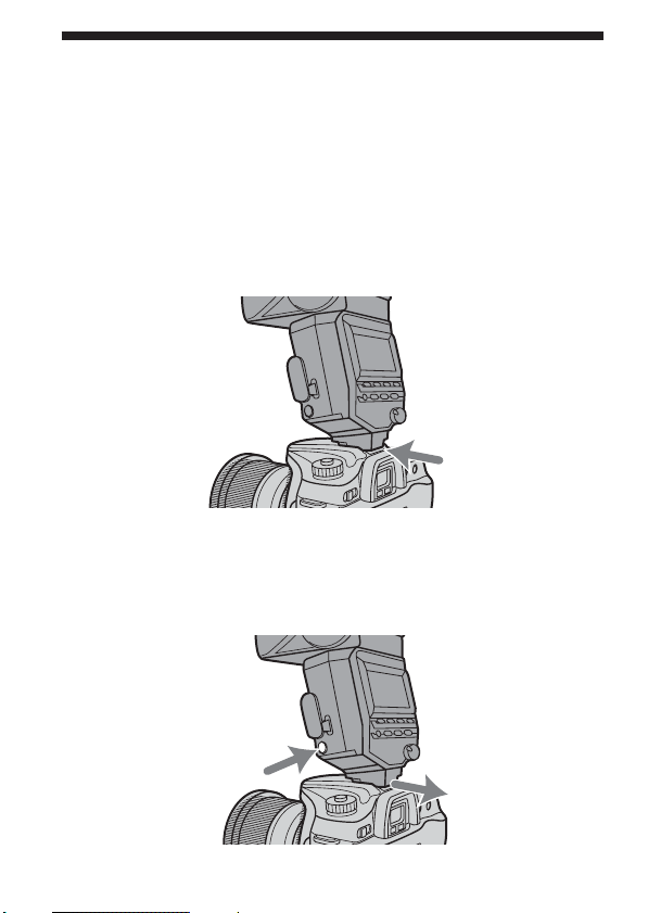
Attaching the flash to the camera
Push the mounting foot firmly onto the camera until it
stops.
• The flash is locked in place automatically.
• If the built-in flash in the camera is protruding, lower it before attaching
the flash unit.
Removing the flash from the camera
While pressing the mounting-foot release button 1,
remove the flash 2.
12
1
2
Page 13
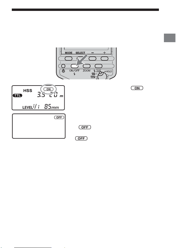
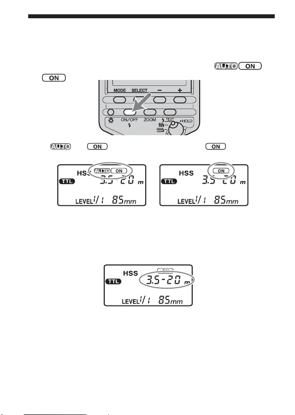
Auto power ON/OFF
Press the flash ON/OFF button on the back side of the
flash.
Power of the flash turns it on.
When the flash is switched on, will
appear on the data panel indicator.
If you press the flash ON/OFF button while
the flash is turned on, the flash switches off
and appears on the data panel
indicator.
• disappears after 8 seconds.
Auto power off
When the camera or flash is not used for four minutes, power switches off
and data panel indicators disappear automatically to save the batteries.
• In wireless flash photography (p. 37), data panel indicators disappear
after 60 minutes.
• The customized settings enable you to disable auto power off or change
the auto power off time (p. 53).
Preparations
13
Page 14
Program auto flash (The basics)
1 Select the P mode on the camera.
2 Press the flash ON/OFF button to display or
.
• and appear with Autoflash. Only appears with
Fill-flash.
3 Press the shutter button partway down and make sure
that the subject is within the flash range.
• See page 16 for details on the flash range.
14
Page 15
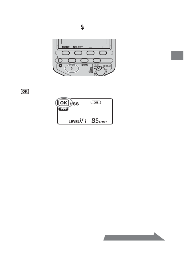
4 When the flash is charged, press the shutter button to
take a photo.
• The flash is charged when indicators on the rear of the unit and in
the camera viewfinder are both lit.
When the correct exposure has been obtained for the photo just taken,
is displayed in the data panel for approximately four seconds.
• The photo will be under-exposed if taken before charging is complete.
• Press the shutter button after making sure that charging is complete
when using the flash with the self-timer.
• Either Autoflash or Fill-flash is selected, depending on your camera. For
details, refer to the operating instructions of your camera.
• If your camera has AUTO mode or Scene Selection mode, they are dealt
with here as program auto.
Basics
Continued on the next page
15
Page 16
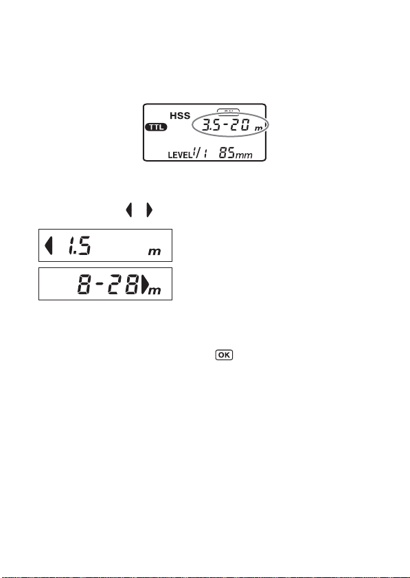
Flash range
Press the shutter button partway down.
The flash range for the proper exposure is displayed on the data panel.
Make sure that the subject is within this range and then take the photo.
The range that can be displayed on the data panel is from 1.5 m to 28 m
(0.7 m to 28 m for downward bounce; see p. 27). When the distance is
beyond this range, or is lit on either side of the viewfinder.
Proper exposure is obtained at less than 1.5
m.
Proper exposure is obtained from 8 m to 28
m or more.
• The flash range is not shown when using flash bounce above and to the
left or right, with wireless flash, or when off-camera cables are used.
• When photographing beyond the lower limit of the flash range, the
photo may be over-exposed despite being displayed, or the bottom
of the picture may darken. Always photograph within the indicated
flash range.
16
Page 17
Recording modes
Aperture priority flash photography (A)
1 Select the A mode on the camera.
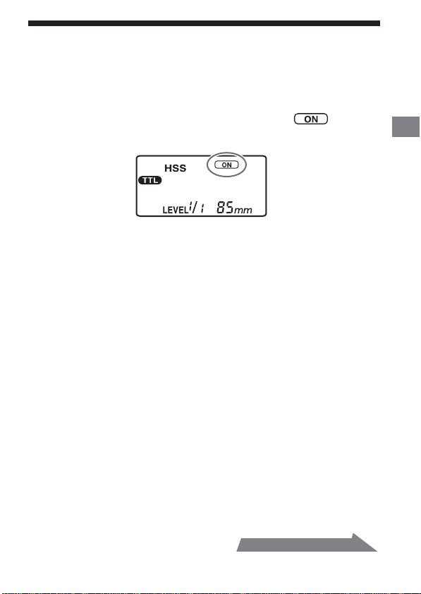
2 Press the flash ON/OFF button to display .
• Fill-flash is selected.
3 Set the aperture and focus the subject.
• Reduce the aperture (i.e. increase the f-stop) to reduce the flash
range, or open the aperture (i.e. reduce the f-stop) to increase the
flash range.
• The shutter speed is automatically set.
4 Press the shutter button when charging is complete.
Basics
Continued on the next page
17
Page 18

Shutter speed priority flash
photography (S)
1 Select the S mode on the camera.
2 Press the flash ON/OFF button to display .
• Fill-flash is selected.
3 Set the shutter speed, and focus the subject.
4 Press the shutter button when charging is complete.
Manual exposure mode flash
photography (M)
1 Select the M mode on the camera.
2 Press the flash ON/OFF button to display .
• Fill-flash is selected.
3 Set the aperture and shutter speed, and focus the
subject.
• Reduce the aperture (i.e. increase the f-stop) to reduce the flash
range, or open the aperture (i.e. reduce the f-stop) to increase the
flash range.
4 Press the shutter button when charging is complete.
18
Page 19
Zoom flash coverage
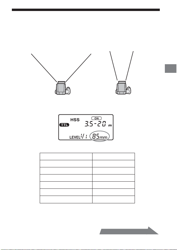
Auto zoom
This flash automatically switches zoom coverage to cover a range of focal
lengths from 24 mm to 85 mm when photographing (auto zoom).
Normally, you do not need to switch the zoom coverage manually.
24 mm focal length 85 mm focal length
• Press the shutter button partway down to display the zoom coverage set
automatically.
• Auto zoom coverage is set as follows:
Focal length in use Coverage
24 mm - 27 mm 24 mm
28 mm - 34 mm 28 mm
35 mm - 49 mm 35 mm
50 mm - 69 mm 50 mm
70 mm - 84 mm 70 mm
85 mm or more 85 mm
• When a lens having a focal length of less than 24 mm is used with auto
zoom, “24 mm” blinks. Use of the built-in wide panel (p. 21) is
recommended in this case to prevent darkening at the periphery of the
image.
Continued on the next page
19
Applications
Page 20
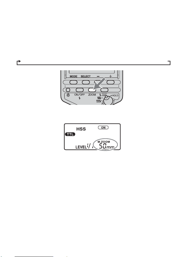
Manual zoom
You can manually set the zoom coverage regardless of the focal length of
the lens in use.
Press the ZOOM button to display the desired zoom
coverage.
• Zoom coverage is changed in the following order.
Auto zoom t 24mm t 28mm t 35mm t 50mm t 70mm t 85mm
• When zoom is set manually, “M.ZOOM” is displayed above zoom
coverage.
• If the zoom coverage is set to less than the focal length of the lens in use,
the periphery of the screen darkens.
20
Page 21
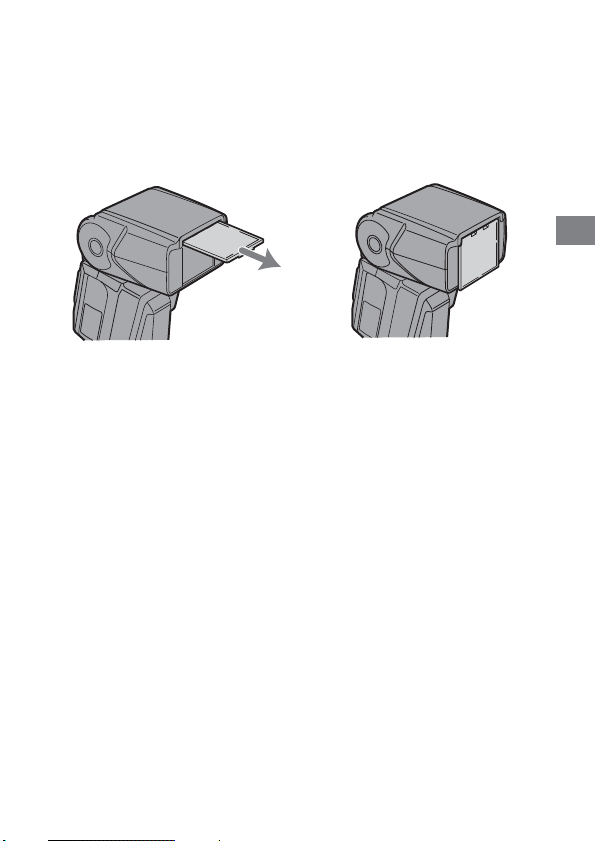
Built-in wide panel (17 mm zoom
angle)
Pulling out the built-in wide panel expands flash coverage to a focal length
of 17 mm.
Pull out the adaptor.
b
• The zoom coverage display on the data panel shows “17 mm.” The flash
range is also displayed.
• When storing the wide panel, insert it in completely.
• When photographing a flat subject from the front at a focal length of
about 17 mm, the periphery of the screen may darken slightly because
the focal distances at the center and periphery of the screen are different.
• When using a wide-angle lens with a focal length below 17 mm, the
periphery of the screen may darken.
Applications
21
Page 22
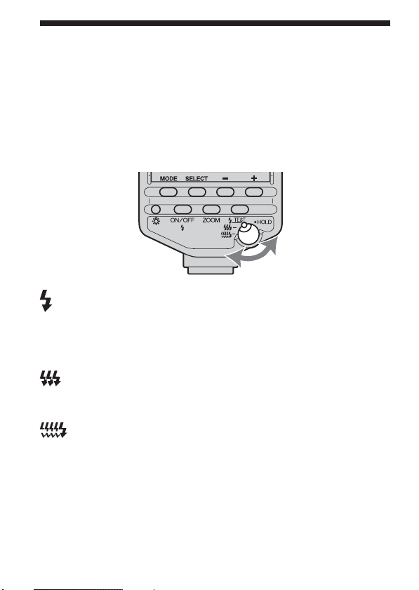
Test-flash/Modeling flash
You can try one or more test flashes before shooting. This is particularly
convenient for checking shadows in wireless flash photography when the
flash is separated from the camera.
* Modeling flash is used to check shadows on the subject before taking
photos.
1 Set the test-flash mode selection/hold switch to the
desired mode.
Flash once at the set light level (LEVEL 1/1 to 1/32).
• Use this test-flash mode when a flash meter is used in manual
flash mode (p. 32).
• In multiple flash mode (p. 46), while pressing the test-flash
button, the flash flashes the number of times you have set.
Flash three times at a rate of two flashes per second (guide
number 5.6 at 24 mm position).
• Used to roughly verify shadows.
Flash 4 seconds at a rate of 40 flashes per second (guide number
1.4 at 24 mm position).
• Convenient for verifying detailed shadows for macro
photography.
HOLD
The setting prevents incorrect operation.
• All flash operations are locked except the test-flash button and
data panel illuminator. The camera can be operated so you can
take photographs.
22
Page 23

2 Press the test-flash/modeling-flash button when
charging is complete.
• Do not press the shutter button while the flash is in use.
• The strength of shadows will differ from that during actual
photography.
• When using the flash in a bright place or outdoors or when using a
bounce flash, shadows are lighter so verification is more difficult.
Applications
23
Page 24
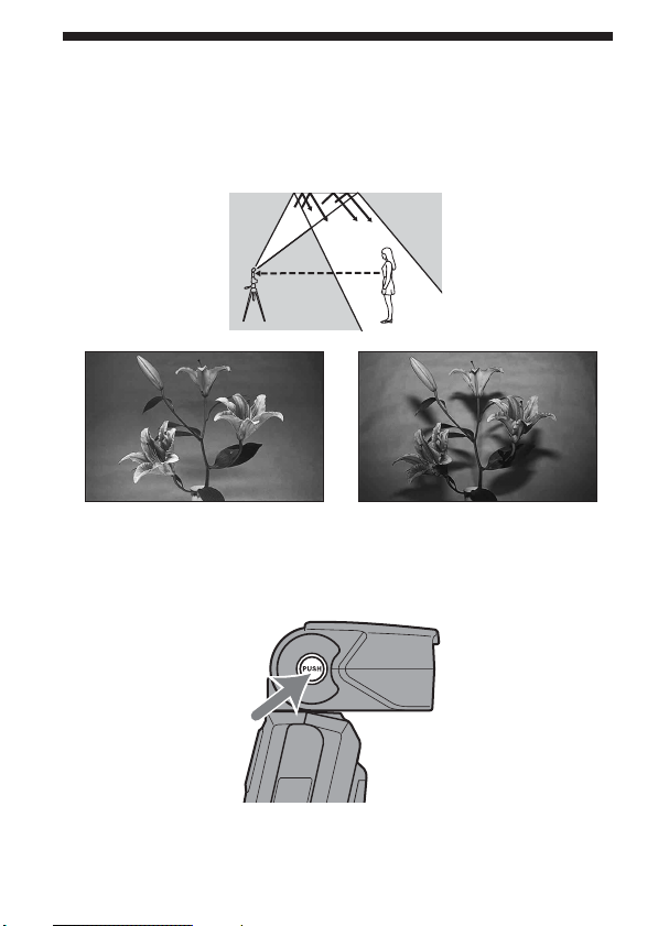
Bounce flash
Using the flash with a wall directly behind the subject produces strong
shadows on the wall. By directing the flash at the ceiling you can
illuminate the subject with reflected light, reducing the intensity of the
shadows and producing a softer light on the screen.
Bounce flash Normal flash
Rotate the flash upwards or to the left and right while
pressing the bounce lock-release button.
24
Page 25
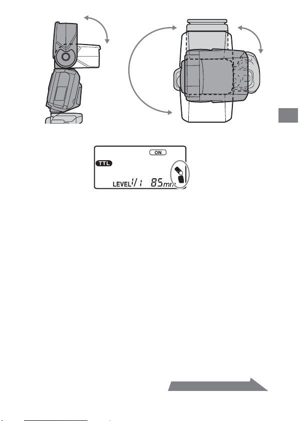
• The bounce indicator appears on the data panel.
The flash may be set to the following angles.
• Upwards: 45°, 60°, 75°, 90°
• Downwards: 10° (see “Close-up Photography” p. 27)
• Right: 30°, 45°, 60°, 75°, 90°
• Left: 30°, 45°, 60°, 75°, 90°, 120°, 150°, 180°
• The bounce lock engages at the 0° position. When the flash is returned to
the original position, the lock-release button needs not to be pressed.
• When the flash is rotated upwards or to the left and right, the flash
range is not displayed on the data panel. High-speed sync is also
cleared.
• Use a white ceiling or wall to reflect the flash. A colored surface may
color the light. High ceilings or glass are not recommended.
Continued on the next page
25
Applications
Page 26
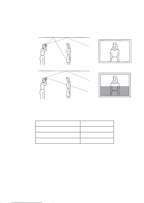
Adjusting bounce angle
Simultaneously using direct light and bounced light from the flash
produces uneven lighting. Determine the bounce angle with respect to the
distance to the reflective surface, the distance from the camera to the
subject, the focal length of the lens etc.
Correct
Incorrect
When flash is bounced upwards
Determine the angle in relation to the following table.
Focal length of lens Bounce angle
70 mm minimum 45°
28-70 mm 60°
28 mm maximum 75°, 90°
Bouncing to Left and Right
Rotating the flash by 90° to bounce light sideways is recommended. If an
angle of less than 90° is used, care should be taken to ensure that direct
light from the flash does not illuminate the subject.
26
Page 27
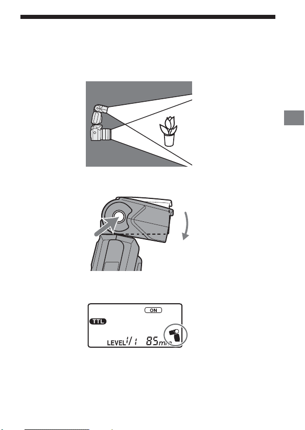
Close-up photography
(downward bounce)
Tilt the flash slightly downwards when photographing objects between 0.7
m and 1.5 m from the camera to ensure accurate illumination.
Rotate the flash downwards while pressing the bounce lockrelease button.
• The downward bounce indicator appears on the data panel.
• The rotation angle is 10°.
Applications
• When photographing at a distance closer than 0.7 m, the flash will not
be able to completely cover the subject and the bottom of the picture will
be darker. Use an off-camera or macro flash.
27
Page 28
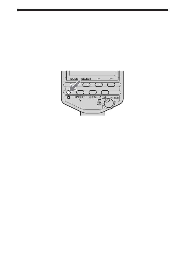
Data panel illuminator
Illuminates the data panel at low-light levels.
Press the data panel illuminator.
• The data panel is illuminated for approximately eight seconds. This
period is extended if the flash is used during this time.
• Press the button again while the data panel is illuminated to extinguish
the data panel illuminator.
28
Page 29
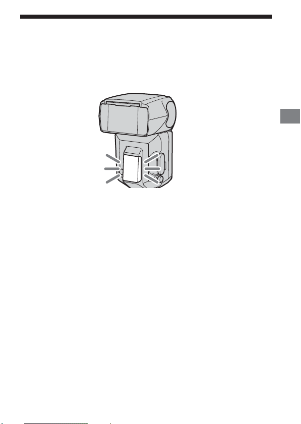
AF illuminator
In low-light or when subject contrast is low, when the shutter button is
pressed partway down for Auto Focus, the red lamp on the front of the
flash unit will light. This is the AF illuminator used as an aid in Auto
Focus.
• The AF illuminator operates even when the flash is off.
• The camera AF illuminator does not operate while the flash AF
illuminator is operating.
• The AF illuminator does not operate while Continuous AF is used in
focusing mode (when continually focusing on a moving subject).
• The AF illuminator may not operate if the focal length of the lens is
greater than 300 mm. The flash will not operate when removed from the
camera.
Applications
29
Page 30
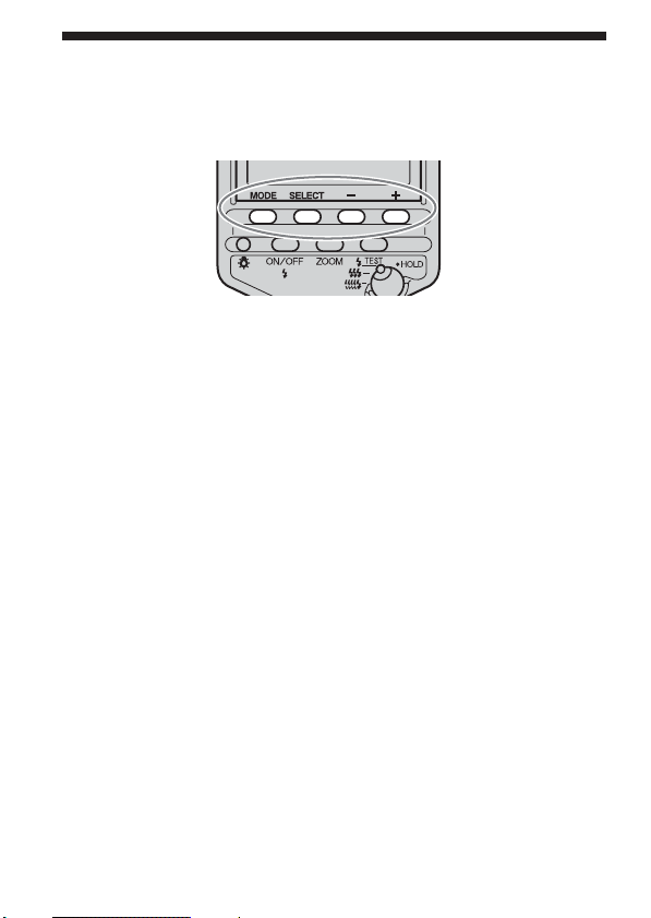
Mode and select buttons
The mode, select, +, and - buttons are used to select the functions described
on the next page.
The functions are selected with the following basic procedure. See the
relevant pages for details.
1 Select the major item with the mode button.
2 Select the minor item with the select button.
3 Make the setting with the + and - buttons.
4 Press the select button* repeatedly until blinking
stops.
* Also possible with the mode button or flash ON/OFF button.
30
Page 31

Selected with Selected with Selected with + and - buttons
the mode button the select button (items in Italics are default settings)
HSS (35) ON,OFF
TTL (32)
M (32) WL (37) OFF,ON
MULTI (46) TIME - - (unlimited), 40, 35, 30, 25, 20,
Figures in parentheses after each item indicate the page numbers.
• Pressing the + and - buttons simultaneously for three seconds restores
the default settings (p. 51).
• Multiple settings which cannot be changed are not displayed.
* This indicator is displayed, but this function is not available.
Use the OFF setting.
WL (37) OFF,ON, CONTROL
RATIO* OFF, , *
LEVEL (44) 1/1,1/2, 1/4, 1/8, 1/16, 1/32
HSS (35) ON,OFF
LEVEL (44) 1/1,1/2, 1/4, 1/8, 1/16, 1/32
Hz 100, 50, 40, 30, 20, 10,
9, 8, 7, 6, 5, 4, 3, 2, 1
15,10,9, 8, 7, 6, 5, 4, 3, 2
LEVEL 1/8, 1/16, 1/32
Applications
31
Page 32

Manual flash (M)
Normal TTL flash metering automatically adjusts the flash intensity to
provide the proper exposure for the subject. Manual flash provides a fixed
flash intensity irrespective of the brightness of the subject and the camera
setting.
• Manual flash can only be used when the camera is in the M mode. In
other modes, TTL measuring is automatically selected.
• As manual flash is not affected by the reflectivity of the subject, it is
convenient for use with subjects with extremely high or low reflectivity.
TTL flash metering Manual flash metering
1 Select the M mode on the camera.
2 Press the mode button to display on the data
panel.
• The modes change in the following order.
, ,
32
Page 33

3 Press the + or – button to select the power level to set.
• The power level can be selected from the following.
1/1, 1/2, 1/4, 1/8, 1/16, 1/32
• For details on setting the power level, refer to page 44.
• When the shutter button is pressed partway down, the distance where
the proper exposure will be obtained will appear in the data panel.
Proper exposure is obtained at less than 1.5 m.
Proper exposure is obtained at more than 28 m.
• The flash indicator is not displayed after a photo is taken with
manual flash.
• Using custom functions, manual flash may be selected without setting
the camera in the M mode (p. 53).
Applications
Continued on the next page
33
Page 34

TTL flash
Manual flash provides a fixed flash intensity irrespective of the
brightness of the subject and the camera setting. TTL* flash measures
the light from the subject that is reflected through the lens.
Some cameras enable P-TTL metering, which adds pre-flash to TTL
metering, and ADI metering, which adds distance data to the P-TTL
metering.
This flash defines all P-TTL and ADI metering as TTL flash and
displays on the data panel.
*TTL = through the lens
• ADI metering is possible in combination with a lens with a built-in
distance encoder.
Before using the ADI metering function, check whether your lens
has a built-in distance encoder by referring to the specifications in
the operating instructions supplied with your lens.
34
Page 35

High-speed sync (HSS)
High-speed sync Normal flash
High-speed sync eliminates the restrictions of flash sync speed and enables
the flash to be used through the entire shutter speed range of the camera.
The increased selectable aperture range allows flash photography with a
wide aperture, leaving the background out of focus and accentuating the
front subject. Even when photographing at a wide f-stop in the A mode or
M mode, when the background is very bright and the shot will normally
be over-exposed, you can adjust the exposure by using the high-speed
shutter.
1 Press the mode button to display or on the
data panel.
2 Press the select button to blink “HSS.”
• The currently selected high-speed sync setting ( / ) also
blinks simultaneously.
Applications
Continued on the next page
35
Page 36

3 Press the + or – button to select .
4 Press the select button repeatedly until blinking stops.
• “HSS” remains on the data panel.
• High-speed sync is cleared when is selected with the
procedure described above, and a shutter speed faster than the sync
speed can no longer be set.
• It is recommended that photos be taken in bright locations. When
photographing in dark areas the shutter speed will not exceed the
sync speed, even when is selected.
• The flash range with high-speed sync is smaller than for normal
flash photography. Make sure that the subject is within the
displayed flash range before taking the photo.
• High-speed sync cannot be used with multiple flash or bounce flash
in the upwards, left, and right directions.
• When using a flash meter or color meter, high-speed sync cannot be
used because it interferes with proper exposure. Either select
to clear it or select a shutter speed lower than the sync speed.
Flash Sync Speed
Flash photography is generally associated with a maximum shutter
speed referred to as the flash sync speed. This restriction does not
apply to cameras designed for high-speed sync (HSS) photography
(p. 35), since they allow flash photography at the maximum shutter
speed of the camera.
36
Page 37

Wireless flash mode (WL)
Photographs taken with the flash attached to the camera are flat as shown
in photo 1. In such cases, remove the flash from the camera and position
it to obtain a more three-dimensional effect as shown in photo 2.
When taking this type of photograph with a single lens reflex camera, the
camera and the flash unit are most commonly connected by a cable. This
flash eliminates the need for a cable to transmit signals to the flash unit by
using the light of the built-in flash itself as a signal. The correct exposure is
determined automatically by the camera.
1
Normal flash Wireless flash
Wireless Flash Range
The wireless flash uses a light signal from the built-in flash as a trigger to
operate the off-camera flash unit. Follow the points below when
positioning the camera, flash, and subject.
• Photograph in dark locations indoors.
• If you rotate the flashtube using bounce-flash function (p. 24) so that the
wireless control-signal receiver points toward the camera, it will be
easier for the flash to receive a signal from the camera.
• Place the off-camera flash within the gray area in the following diagram.
2
Applications
Continued on the next page
37
Page 38

Distance between camera
and subject (see Table 1)
Place the camera and flash unit
within a 5 m radius of the
subject
Distance between flash and
subject (see Table 2)
Do not place the flash
directly behind the subject
Distance camera-HVL-F56AM-subject
Distance
Shutter
speed
Aperture
camera- subject
(Table 1)
All shutter
speeds
Other than HSS HSS
Maximum
1/60 sec
2.8 1.4 - 5 1.4 - 5 1 - 5 1 - 5 1 - 3.5 1 - 2.5 1 - 1.7 1 - 1.2
41 - 51 - 5 1 - 5 1 - 3.5 1 - 2.5 1 - 1.7 1 - 1.2 –
5.6 1 - 5 1 - 5 1 - 5 1 - 2.5 1 - 1.7 1 - 1.2 – –
• The distances in the above table assume the use of ISO 100. If ISO 400 is
used the distances must be multiplied by a factor of two (assume a limit
of 5 m).
• With wireless flash, the flash range is not shown on the data panel.
Distance HVL-F56AM - subject (Table 2)
1/60 to
1/250
1/500
sync
speed
sec
sec
1/1000
sec
1/2000
sec
1/4000
sec
Units: m
38
Page 39

Notes on wireless flash
• You cannot use a flash meter or color meter in wireless flash mode
because the camera’s built-in pre-flash goes off.
• Test flash for the wireless flash is in the currently selected test flash
mode. Three flashes occur with and flashes continue for four
seconds with . One flash occurs at the HOLD position.
• The zoom position for the HVL-F56AM is automatically set to 24 mm. A
zoom position other than 24 mm is not recommended.
• In wireless flash mode, ADI metering is canceled and P-TTL flash
metering is used automatically (p. 34).
• Multiple flash cannot be used.
• If another wireless flash is being used nearby, you can change the
channel using custom settings to prevent interference (p. 52).
• When photographing with the wireless flash, the flash may in rare cases
go off by mistake due to ambient static electricity or electromagnetic
noise.
When the flash is not in use, turn it off using the flash ON/OFF button.
Attaching and removing the mini-stand
• Use the supplied mini-stand when the flash unit is separate from the
camera.
• You can attach the flash unit to a tripod using the tripod socket holes in
the mini-stand.
Applications
Attachment
Removal
Continued on the next page
39
Page 40

[1] Photography with wireless flash
Use only an off-camera flash unit, using the light from the built-in flash as
a signal.
1 Attach the flash to the camera and turn the power of
the flash and camera on.
2 Set the camera to wireless flash.
• When the camera is set to wireless the flash is also set to wireless
automatically, and WL is displayed on the data panel.
The flash channel information is transmitted to the camera.
3 Remove the flash from the camera and raise the built-
in flash.
4 Set up the camera and flash.
• See page 38 for details.
40
Page 41

5 Make sure that the built-in flash and flash are fully
charged.
• is lit in the viewfinder when the built-in flash is fully charged.
• The AF illuminator on the front blinks, and on the rear is lit, when
the flash is fully charged.
6 Use test flash to check the flash.
• The test flash method differs depending on the camera used. For
details, see the operation instructions of your camera.
• If the test flash does not work, change the position of the camera,
flash and subject, or point the wireless control-signal receiver
towards the camera.
7 Check again that the built-in flash and the flash are
fully charged, and press the shutter button to take the
photo.
• Do not take photos when RATIO is displayed on the data panel. The
exposure may not be correct.
Applications
Continued on the next page
41
Page 42

[2] Setting wireless flash by flash only
Once you have performed the wireless flash setup in step [1], if you
continue to use the same camera and flash combination without changing
the wireless channel then you can also set the flash and camera separately
to wireless.
Camera setting:
Set to the wireless flash mode.
For details, refer to the operating instructions supplied with your camera.
Flash setting:
1 Press the mode button to display or .
2 Press the select button repeatedly to blink “WL.”
• The current wireless setting “OFF” is also displayed.
3 Press the + or - button to blink “WL On.”
4 Press the select button repeatedly until blinking stops.
42
Page 43

Connecting camera and flash by
cable
Using the off-camera cables FA-CC1AM (optional) allows photography
with flash units separate from the camera. Up to four flash units can be
connected together. Being able to take photographs without having to
consider the positioning of the flash unit provides considerable freedom to
create a variety of shadow effects on the subject.
• Flash units with accessory terminals can be connected directly.
1 Remove the terminal cap.
2 Plug the cable into the accessory terminal.
Applications
• In this mode, ADI metering will be canceled and Pre-flash TTL
metering will be used automatically (p. 34).
• High-speed sync in the P mode cannot be used when the flash is
connected with the off-camera cable FA-CC1AM (optional).
• All the flash units are at the same power level.
43
Page 44

Setting power level (LEVEL)
The power level for the flash can be adjusted.
1 Press the select button to display “LEVEL” on the data
panel.
• The current level is displayed.
• This step is not required when manual flash is selected. Go to step 2.
2 Press the + or – button to select the power level to be
set.
• With TTL or manual flash photography the power level may be
selected from the following.
1/1, 1/2, 1/4, 1/8, 1/16, 1/32
• With multiple flash photography the power level may be selected
from the following.
1/8, 1/16, 1/32
44
Page 45

3 Press the select button.
• When the power level is changed, the distance displayed on the data
panel changes accordingly.
• Power level settings can be set independently for TTL photography
, manual flash photography and multiple photography
.
• In TTL flash photography, the power level will be adjusted with the
selected level at its maximum.
• In manual flash photography, if the power level is set at 1/1 then the
flash will go off at full power. The power level range (e.g. 1/1 t 1/2)
corresponds to the aperture range (e.g. F4 t 5.6).
Applications
45
Page 46

Multiple flash (MULTI)
The flash is triggered a number of times while the shutter is open (multiple
flash). Multiple flash allows motion of the subject to be captured in a
photograph for later analysis.
• The camera must be set to the M mode for multiple flash photography.
Multiple flash can only be used if the camera supports the M mode.
1 Set the camera to the M mode.
2 Press the mode button to display of the data
panel.
46
Page 47

3 Press the select button to blink “Hz.”
• The current multiple flash frequency (flashes per second) is
displayed on the data panel.
4 Press the + or – button to select the flash frequency.
• The flash frequency may be selected from the following.
100, 50, 40, 30, 20, 10, 9, 8, 7, 6, 5, 4, 3, 2, 1
• Keep the + or – button pressed down to repeatedly change the
value.
Applications
Continued on the next page
47
Page 48

5 Press the select button to blink “TIMES.”
• The current number of flashes for multiple flash is displayed on the
data panel.
6 Press the + or – button to select the number of flashes.
• The number of flashes may be selected from the following.
- -, 40, 35, 30, 25, 20, 15, 10, 9, 8, 7, 6, 5, 4, 3, 2
• Keep the + or – button pressed down to repeatedly change the
value.
• When “--” is selected, flashes continue at the set frequency while the
shutter is open.
7 Press the select button to blink “LEVEL” on the data
panel.
• The current power level is displayed.
48
Page 49

8 Press the + or – button to select the power level to set.
• The power level may be selected from the following.
1/8, 1/16, 1/32
9 Press the select button.
10Set the shutter speed and aperture.
• The shutter speed is calculated as follows to suit the selected flash
frequency and number of flashes.
Number of flashes (TIME) ÷ Flash frequency (Hz) ≤ Shutter speed
For example, when ten flashes and 5 Hz are selected, 10 ÷ 5 = 2
requires a shutter speed of longer than two seconds.
11When the flash is fully charged, press the shutter
button to take the photo.
• The distance at which the proper exposure is obtained with a single
flash is displayed on the data panel.
• To prevent shaking, the use of a tripod is recommended during
multiple flash photography.
• Test flash will flash at the selected frequency/number/level while
the test-flash button is being pressed if the selection switch is at or
HOLD.
• The use of custom settings allows the camera to be set up for
manual flash photography without selecting the M mode (p. 54).
Applications
Continued on the next page
49
Page 50

Maximum number of continuous flashes
The maximum number of continuous flashes during multiple flash
photography is limited by the charge in the battery. Use the following
values as a guide.
With alkaline batteries
Power
level
100
50 40 30 20 10 9 8 7 6 5 4 3 2 1
1/8 3 4 4 4 5 5 5 5 56677710
1/16 5 6 7 8 8 9 9 10 10 10 10 10 15 20 40
1/32 10 10 10 15 15 20 20 20 25 30 40 40* 40* 40* 40*
Flash frequency (Hz)
With nickel-metal hydride batteries (When using 1550 mAh)
Power
level
100
50 40 30 20 10 9 8 7 6 5 4 3 2 1
1/8
34445555566771020
1/16 5 6 7 8 8 9 9 10 10 10 10 15 20 40 40*
1/32 10 15 15 15 15 20 25 25 30 40 40* 40* 40* 40* 40*
• The maximum number of flashes varies with the type of battery and its
condition. If the external battery adaptor FA-EB1AM (optional) is used,
the maximum number of flashes increases beyond the values given
above.
Flash frequency (Hz)
*40 signifies more than 40.
50
Page 51

Reset to default settings
Press the + and - buttons together for three seconds.
Most flash functions return to default settings.
Item Default settings Page
Flash on/off On (Auto on or on) 13
Flash coverage (zoom) Auto zoom (85 mm) 19
Flash mode (TTL/M/MULTI) TTL 32
High speed sync (HSS) On 35
Wireless flash (WL) Off 37
Ratio control (RATIO)* Off –
Power level in TTL/M (LEVEL) 1/1 44
Power level in multiple flash (LEVEL) 1/32 49
Frequency in multiple flash (Hz) 5 47
Repetition in multiple flash (TIMES) 10 48
Applications
* This indicator is displayed, but this function is not available.
Custom setting is not reset.
51
Page 52

Custom setting
The various flash settings may be changed as necessary.
The following five items may be changed.
• Wireless channel setting (channels 1 to 4)
• Flash range units (m/ft)
• Time to auto power off (4 minutes/15 minutes/60 minutes/none)
• Time to auto power off when using wireless flash (60 minutes/none)
• Recording modes in which manual flash and multiple flash may be set
(M mode only/all modes)
1 Press the select button for 3 seconds.
• The first item (wireless channel setting) is displayed.
2 Press the select button to select the item, and press the
+ or – button to select the desired setting.
• Each time the select button is pressed, the above five items appear
on the data panel (see following page).
52
Page 53

Select with the + button or – button
1. Wireless channel setting
Channel 1 Channel 2
Channel 3 Channel 4
2. Flash range units (m/ft)
mft
3. Time to auto power off
4 minutes 15 minutes 60 minutes none
4. Time to auto power off when using wireless flash
Select with the select button
60 minutes none
5. Recording modes in which manual flash and multiple flash
may be set
M mode only All modes
Continued on the next page
Applications
53
Page 54

3 Press the mode button.
• The data panel returns to the original display.
• When a setting other than the default setting is selected in custom 3,
4 or 5, remains on the data display.
• After changing the wireless flash channel (see 1. Wireless channel
setting), attach the flash to the camera, and press the shutter button
partway down to transmit the flash channel information to the
camera.
• When “All modes” is selected (see 5. Recording modes in which
manual flash and multiple flash may be set), manual flash and
multiple flash photography may be used in all recording modes.
* The proper exposure may not be obtained with photography in
modes other than the M mode, and use of the M mode is therefore
recommended.
• The selected settings are maintained even when the flash unit is
turned off, or the battery is removed.
54
Page 55

Accessories
Off-Camera Accessories
• Off-camera cable
FA-CC1AM
• Off-camera shoe
FA-CS1AM
• Extension cable
FA-EC1AM
• Multi flash cable
FA-MC1AM
The flash can be used from any position
removed from the camera.
• The off-camera cable can be connected
directly to the flash’s accessory terminal
without using the off-camera shoe.
Additional Information
The off-camera cable FA-CC1AM can be
further extended.
Connecting flashes with multi flash cables
enables photography with multiple flash
units.
• Triple connector
FA-TC1AM
Connecting the off-camera cable FACC1AM or extension cable FA-EC1AM
enables photography with up to three
flashes at the same time.
Continued on the next page
55
Page 56

External Battery Adaptor
FA-EB1AM
The external battery adaptor contains six
AA-size batteries. It reduces charging
time by half, and doubles the number of
flashes possible.
56
Page 57

Notes on use
While shooting
• This flash unit generates strong light, so it should not be used directly in
front of the eyes.
Batteries
• The battery level displayed on the data panel may be lower than the
actual battery capacity, temperature, and storage conditions. The
displayed battery level is restored to the correct value after the flash has
been used a few times. When blinks to indicate that the flash
cannot be used, pressing the flash ON/OFF button a number of times
may result in restoration of the correct battery level display. If the
battery level is still not restored, replace the battery.
• When using lithium batteries, if the batteries become hot due to high
temperature or continuous use, may blink and the flash may not
work for a while. Wait for the batteries to cool down before using the
flash again.
• Nickel-metal hydride batteries can lose power suddenly. If starts
blinking or the flash can no longer be used while taking pictures, change
or recharge the batteries.
• The flash frequency and number of flashes provided by new batteries
may vary from the values shown in the table, depending on the time
elapsed since manufacture of the batteries.
Additional Information
Continued on the next page
57
Page 58

Temperature
• The flash unit may be used over a temperature range of 0 °C to 40 °C.
• Do not expose the flash unit to extremely high temperatures (e.g. in
direct sunlight inside a vehicle) or high humidity.
• The response of the data panel slows as the temperature decreases, and
the panel darkens at high temperatures. Restore it to normal
temperature if these problems occur.
• To prevent condensation forming on the flash, place it in a sealed plastic
bag when bringing it from a cold environment into a warm
environment. Allow it to reach room temperature before removing it
from the bag.
• Battery capacity decreases at colder temperatures. Keep your camera
and spare batteries in a warm inside pocket when shooting in cold
weather. may blink even when there is some power left in the
batteries in cold weather. Batteries will regain some of their capacity
when warmed to normal operating temperature.
• This flash unit is not waterproof. Be careful not to bring it into contact
with water or sand when using it at the seashore, for example. Contact
with water, sand, dust, or salt may result in a malfunction.
Maintenance
Remove this unit from the camera. Clean the flash with a dry soft cloth. If
the flash has been in contact with sand, wiping will damage the surface,
and it should therefore be cleaned gently using a blower. In the event of
stubborn stains, use a cloth lightly dampened with a mild detergent
solution, and then wipe the unit clean with a dry soft cloth. Never use
strong solvents, such as thinner or benzine, as these damage the surface
finish.
58
Page 59

Specifications
Guide number
Normal flash (ISO 100)
Power level 17 24 28 35 50 70 85
1/1 18 30 32 38 44 50 56
1/2 12 21 22 26 31 35 38
1/4 9 15 1619222527
1/8 6.4 10 11 13 15 17 19
1/16 4.5 7.5 8 9 11 12 13
1/32 3.2 5.3 5.7 6.7 7.8 8.8 9.7
Wireless flash (ISO 100)
Power level 17 24 28 35 50 70 85
1/1 14 25 26 30 35 41 42
HSS flat flash (flash with HSS, ISO 100)
Shutter speed
1/250 6.7 12 13 15 17 19 22
1/500 4.5 8.6 9.5 10 12 13 16
1/1000 3.5 6 6.7 7.5 9 9.5 11
1/2000 2.4 4.3 4.5 5 6 6.7 8
1/4000 1.7 3 3.5 3.7 4.5 4.7 5.6
1/8000 1.2 2.1 2.4 2.5 3 3.5 4
1/12000 1 1.8 2 2.1 2.5 2.8 3.5
Flash Coverage Setting (mm)
Additional Information
Flash Coverage Setting (mm)
Flash Coverage Setting (mm)
17 24 28 35 50 70 85
Continued on the next page
59
Page 60

Frequency/Repetition
Alkaline Lithium
Frequency (sec)
Repetition (times)
• Repetition is the approximate number of times that are possible before a
new battery is completely dead.
Flash coverage
Flash coverage
Top-bottom (° )
Left-right
Continuous 40 flashes at 5 flashes per second
flash performance (Normal flash, power level 1/32, nickel-metal
AF illuminator Autoflash at low contrast and low brightness
Flash control Flash control using pre-flash, TTL direct metering,
Dimension (Approx.) W 77.5 × H 132 × D 95.5 mm
Mass (Approx.) 370 g (13.1 oz)
Included items Flash (1), Mini-stand (1), Case (1),
(° )
hydride battery)
For wide focus area
Operating range
(with a 50 mm lens attached to α100)
Manual flash
(3 1/8 × 5 1/4 × 4 inches)
Set of printed documentation
0.2 - 11 0.2 - 13 0.2 - 8
90 - 3200 250 - 8000 80 - 2800
Flash Coverage Setting (mm)
17 24 28 35 50 70 85
115 60 53 45 34 26 23
125 78 70 60 46 36 31
Central area: 0.5 m to 10 m
Peripheral areas: 0.5 m to 3 m
Nickel hydride
(1550 mAh)
Functions in these operating instructions depend on testing conditions at
our firm.
Design and specifications are subject to change without notice.
60
Page 61

Trademark
is a trademark of Sony Corporation.
61
Page 62

Français
Avant de faire fonctionner ce produit, lisez attentivement ce mode
d’emploi et conservez-le pour toute référence ultérieure.
AVERTISSEMENT
Afin de réduire les risques d’incendie ou de décharge électrique, n’exposez
pas cet appareil à la pluie ou à l’humidité.
Scotcher les contacts des piles lithium avant de les jeter. Suivre les
éventuelles consignes locales sur le rejet des piles.
Ne pas laisser les piles ou de petits accessoires à la portée de jeunes enfants
qui pourraient les avaler. En cas d’ingestion accidentelle, contacter
immédiatement un médecin.
Retirer immédiatement les piles du flash si :
• L’appareil est tombé ou a reçu un choc à la suite duquel il s’est brisé et
laisse apparaître ses composants internes.
• L’appareil chauffe anormalement ou émet une fumée ou une odeur
étrange.
Ne pas démonter le flash. Risque d’électrocution lié à la présence de
circuits haute tension.
CONSIGNES DE SECURITE
IMPORTANTES
Lors de l’utilisation de votre matériel photographique, il
convient d’observer des précautions de sécurité de base, à
savoir, entre autres :
Prendre connaissance de toutes les instructions à respecter
avant toute utilisation.
Lorsqu’un appareil est utilisé par un enfant ou à proximité
d’un enfant, une surveillance attentionnée est obligatoire.
2
Page 63

Ne pas laisser l’appareil sans surveillance pendant
l’utilisation.
Il convient d’être prudent car les parties chaudes peuvent
entraîner des brûlures.
Ne pas utiliser l’appareil lorsque le cordon est endommagé
ou si l’appareil est tombé ou a été endommagé, tant qu’il
n’a pas été examiné par un technicien qualifié.
Laisser l’appareil refroidir complètement avant de le
ranger. Enrouler le cordon autour de l’appareil sans le
serrer lors du rangement.
Pour réduire les risques d’électrocution, ne pas immerger
cet appareil dans l’eau ou d’autres liquides.
Pour réduire les risques d’électrocution, ne pas démonter
cet appareil et confier l’entretien ou les réparations
éventuelles à un technicien qualifié. Un montage incorrect
peut entraîner une électrocution lors de l’utilisation
suivante de l’appareil.
L’utilisation d’un dispositif de fixation pour accessoires non
recommandé par le fabricant peut constituer un risque
d’incendie, d’électrocution ou de blessure des personnes.
Les piles peuvent chauffer ou exploser suite à une
utilisation incorrecte.
Utiliser uniquement les piles indiquées dans ce mode
d’emploi.
Ne pas mettre les piles en place avec une polarité inversée
(+/-).
Ne pas soumettre les piles au feu ou à de fortes
températures.
Ne pas essayer de les recharger (sauf pour les piles
rechargeables), ne pas les mettre en court-circuit, ne pas les
démonter.
Ne pas mélanger différents types et différentes marques de
piles, ni des piles anciennes et nouvelles.
3
Page 64

CONSERVER CES
CONSIGNES
ATTENTION
Lors de l’émission de l’éclair, le tube à éclairs peut être très chaud. Ne pas
la toucher.
Pour les clients en Europe
Traitement des appareils électriques et électroniques en
fin de vie (Applicable dans les pays de l’Union
Européenne et aux autres pays européens disposant de
systèmes de collecte sélective)
Ce symbole, apposé sur le produit ou sur son emballage,
indique que ce produit ne doit pas être traité avec les déchets
ménagers. Il doit être remis à un point de collecte approprié
pour le recyclage des équipements électriques et
électroniques. En s’assurant que ce produit est bien mis au
rebut de manière appropriée, vous aiderez à prévenir les
conséquences négatives potentielles pour l’environnement et
la santé humaine. Le recyclage des matériaux aidera à
préserver les ressources naturelles. Pour toute information
supplémentaire au sujet du recyclage de ce produit, vous
pouvez contacter votre municipalité, votre déchetterie ou le
magasin où vous avez acheté le produit.
Marque commerciale
est une marque commerciale de Sony Corporation.
4
Page 65

Table des matières
Caractéristiques ...................... 6
Nomenclature.......................... 7
Panneau de commande..........8
Ecran .........................................9
Préparations
Mise en place des piles.........10
Montage et démontage du
flash.........................................12
Mise en marche/Arrêt
automatique...........................13
Principes de base
Flash en mode de
programmation automatique
(principes de base) ................14
Modes d’enregistrement ......17
Applications
Couverture de la tête-réflecteur
Zoom ...................................... 19
Touche test/lampe pilote.....22
Flash indirect .........................24
Photographie rapprochée
(inclinaison vers le bas)........ 27
Éclairage de l’écran...............28
Illuminateur AF.....................29
Touches mode et sélection ...30
Flash manuel (M) ..................32
Synchro haute vitesse
(HSS) .......................................35
Flash sans cordon (WL) ....... 37
Raccordement de l’appareil
photo et du flash à l’aide d’un
câble ........................................ 43
Réglage du niveau de
puissance (LEVEL) ............... 44
Mode éclairs multiples
(MULTI).................................. 46
Réinitialisation aux réglages
par défaut ............................... 51
Fonctions personnalisables
................................................. 52
Informations
complémentaires
Accessoires.............................55
Remarques sur l’utilisation
................................................. 57
Entretien .................................58
Caractéristiques .................... 59
5
Page 66

Avant la première utilisation
Pour plus d’informations, reportez-vous au mode d’emploi fourni avec
votre appareil photo.
Ce flash n’est pas étanche à la poussière, aux gouttes ni à
l’eau.
Ne pas le placer dans les endroits suivants :
Où que vous utilisiez ou stockiez cet appareil, ne le placez pas dans les
endroits suivants. Ceci pourrait entraîner un problème de fonctionnement.
• Placer ce flash dans des endroits soumis à la lumière directe du soleil
comme sur un tableau de bord ou à proximité d’un radiateur peut
entraîner sa déformation ou un dysfonctionnement.
• Endroits soumis à des vibrations excessives
• Endroits soumis à de fortes ondes magnétiques
• Endroits sablonneux
Prenez garde à ne pas exposer cet appareil au sable lorsque vous êtes
sur une plage ou dans des zones sablonneuses.
Ceci pourrait entraîner un problème de fonctionnement.
Caractéristiques
• Le flash HVL-F56AM est un flash compact à pince qui offre une large
sortie de flash avec un nombre guide de 56 (position 85 mm,
ISO 100 · m).
• Le diffuseur grand angle intégré étend la couverture du flash à une
longueur focale de 17 mm.
• Le flash HVL-F56AM assure une mesure au flash ADI (Advanced
Distance Integration) très fiable lorsqu’il est utilisé avec des objectifs
compatibles.
• Le flash HVL-F56AM gère les photographies synchro haute vitesse sans
cordon.
• La tête du flash bascule à un angle de 90° vers le haut, 180° vers la
gauche et 90° vers la droite pour le flash indirect (avec la fonction de
verrouillage) et 10° vers le bas pour une prise de vue en gros plan.
* Selon l’appareil photo, cette fonction peut être inopérante.
6
Page 67

Nomenclature
Adaptateur grandangle intégré (21)
A l’intérieur
• Prise accessoires (43)
• Prise d’alimentation externe(56)
Tube à éclairs
Illuminateur AF
(29)
Récepteur de
signaux sans
cordon (37)
Indicateur
d’orientation
verticale (24)
Panneau de
données (9)
Panneau de
commande (8)
Couvercle des
prises de
raccordement
Bouton de
déverrouillage du
sabot (12)
Sabot
Bouton de
déverrouillage de
la tête-réflecteur
(24)
Volet-couvercle
du compartiment
des piles (10)
Retirer la feuille de protection de l’avant de
l’illuminateur AF avant utilisation.
7
Page 68

Panneau de commande
Touche SELECT
Touche MODE
Touche
d’éclairage de
l’écran (28)
Touche ON/OFF
(marche/arrêt) du
flash (13)
Témoin de charge du
flash (15)
Touche -
Touche +
Touche test /
Touche de
simulation de
lampe pilote (23)
Sélection du mode
lampe pilote / Touche
de sécurité (HOLD)
(22)
Touche de sélection
ZOOM (couverture du
flash) (20)
8
Page 69

Ecran
Indicateur de synchro
haute vitesse (35)
Indicateur de mode
flash sans cordon
(40-42)
Indicateur de bonne
exposition (15)
Indicateur sans
cordon*
Indicateurs de limites de portée (16)
Couverture du flash (16) /
fréquence d’éclairs (47)
Indication de
fréquence Hz (47)
Indicateurs de flash ON/
OFF (14)
Indicateur de
mode TTL (32)
Indication
d’unités m
ou ft (53)
Indicateur de
mode manuel
(32)
Indicateur de
mode éclairs
multiples (46)
Indicateur de
fonction
personnalisable
(52)
Indicateur de ratio de
puissance*
Cet indicateur s’affiche
*
mais sa fonction n’est pas
disponible.
Indicateur du niveau de
puissance (44)
Indication de zoom (19,20) / de
répétition en mode éclairs
Indicateur de zoom
manuel (20)
multiples (48)
Indication de focale en mm
(19)
Indicateur de
piles faibles (11)
Indicateur de
flash indirect
(24)
Indication TIMES
(nombre d’éclairs)
(48)
Sur cette page, tous les indicateurs sont affichés à des fins d’explication.
9
Page 70

Mise en place des piles
Le HVL-F56AM peut être alimenté par :
*Les piles ne sont pas fournies.
•4 piles alcalines type AA
•4 piles lithium type AA
•4 piles Ni-MH (nickel-métal hydrure) rechargeables type AA
S’assurer que ces piles sont bien rechargées avec le chargeur adapté.
1 Ouvrir le compartiment des piles comme indiqué.
2 Mettre les piles en place en respectant les polarités
indiquées sur le schéma figurant dans le compartiment.
3 Refermer le compartiment.
• Exécuter les étapes dans le sens inverse lors de l’ouverture du
compartiment.
• Le témoin de piles apparaît sur l’écran d’affichage. Appuyer sur la
touche ON/OFF s’il n’apparaît pas.
10
Page 71

Vérification de l’état des piles
Le pictogramme clignote à l’écran si les piles sont en fin de capacité.
Le pictogramme clignote
Il est recommandé de changer les
piles. Le flash peut encore être utilisé
dans cet état si (témoin de charge
du flash), situé à l’arrière de
l’appareil, est allumé.
Seul le pictogramme clignote
Le flash ne peut plus fonctionner.
Remplacer les piles.
• Vérifier la mise en place des piles si rien n’apparaît sur l’écran après
avoir appuyé sur la touche ON/OFF
Préparations
11
Page 72

Montage et démontage du flash
Montage du flash sur l’appareil photo
Pousser fermement le sabot sur l’appareil photo jusqu’à ce
qu’il s’encliquette.
• Le flash est automatiquement verrouillé en place.
• Si le flash intégré de l’appareil photo est déployé, le rabattre avant de
monter le flash.
Retrait du flash de l’appareil photo
Tout en appuyant sur le bouton de déverrouillage 1 du
sabot, retirer le flash 2.
12
1
2
Page 73

Mise en marche/Arrêt
automatique
Appuyez sur la touche ON/OFF situé à l’arrière du flash.
Lorsque le flash est alimenté, il se met sous tension.
Lorsque le flash est sous tension,
apparaît sur l’écran d’affichage.
Si vous appuyez sur la touche ON/OFF du
flash alors que le flash est sous tension, le
flash s’éteint et apparaît sur l’écran
d’affichage.
• disparaît au bout de 8 secondes.
Arrêt automatique
Le flash est automatiquement mis hors tension et l’écran s’éteint afin
d’économiser les piles lorsque l’appareil photo ou le flash n’a pas été
utilisé pendant 4 minutes.
• Lors de prise de vues avec le flash détaché de l’appareil (p. 37), les
indicateurs de l'écran disparaissent au bout de 60 minutes.
• Les fonctions personnalisées peuvent être utilisées pour modifier la
durée de la temporisation ou pour annuler l’arrêt automatique (p. 53).
Préparations
13
Page 74

Flash en mode de programmation
automatique (principes de base)
1 Sélectionner le mode P sur l’appareil photo.
2 Appuyer sur la touche ON/OFF du flash pour afficher
ou .
• et s’affichent pour indiquer le mode flash
automatique. s’affiche seul pour le mode Fill-flash.
3 Appuyez à mi-course sur le déclencheur et vérifiez que
le sujet est bien dans la plage de portée du flash.
• Pour plus d’informations sur la portée du flash, voir page 16.
14
Page 75

4 Lorsque le flash est chargé, appuyez sur le déclencheur
pour prendre une photo.
• Le flash est chargé lorsque les indicateurs situés à l’arrière du
flash et dans le viseur sont allumés.
Lorsque l’exposition de la photo qui vient d’être prise est bonne,
s’affiche sur l’écran de contrôle durant environ quatre secondes.
• La photo risque d’être sous-exposée si le déclenchement intervient après
la fin de la charge du flash.
• Lors de l’utilisation du retardateur, appuyez à fond sur le déclencheur
seulement lorsque la charge du flash est terminée.
• Le mode flash automatique ou Fill-flash est sélectionné, selon votre
appareil photo. Pour plus d’informations, reportez-vous au mode
d’emploi de votre appareil photo.
• Si votre appareil photo comporte le mode automatique ou de sélection
de scène, ces modes sont gérés ici comme des modes automatiques
programmés.
Principes de base
Suite à la page suivante
15
Page 76

Portée du flash
Appuyez à mi-course sur le déclencheur.
Affiche la plage de distances de portée du flash sur l’écran de contrôle.
Vérifier que le sujet est bien situé dans cette plage de distances avant de
prendre la photo.
L’écran peut afficher des plages de distances comprises entre 1,5 m et 28 m
(0,7 m et 28 m en position réflecteur incliné vers le bas, voir page 27). Si la
distance est en dehors de cette plage, ou est allumé sur l’un des côtés
du viseur.
L’exposition sera correcte pour un sujet à
moins de 1,5 m.
L’exposition sera correcte pour un sujet
entre 8 m et 28 m ou plus.
• La portée du flash n’est pas affichée en flash indirect (tête-réflecteur
orientée vers le haut ou vers la gauche ou la droite), ni en mode flash
sans cordon ou en flash détaché avec cordons de liaison.
• En prise de vues rapprochée à distance inférieure à la limite de portée
minimum du flash, la photo risque d’être surexposée bien que le témoin
soit affiché ou que le bas de la photo soit sombre. Toujours
photographier en respectant les limites de portée du flash.
16
Page 77

Modes d’enregistrement
Prise de vue en mode flash priorité
d’ouverture (A)
1 Sélectionner le mode A sur l’appareil photo.
2 Appuyer sur la touche ON/OFF du flash pour afficher
.
• Le mode Fill-flash est sélectionné.
3 Régler l’ouverture et faire le point sur le sujet.
• Pour diminuer la portée du flash, diminuer l’ouverture (nombre
plus grand). Pour augmenter la portée, augmenter l’ouverture.
• La vitesse d’obturation est automatiquement réglée.
4 Appuyez à fond sur le déclencheur lorsque le flash est
chargé.
Principes de base
Suite à la page suivante
17
Page 78

Prise de vue en mode flash priorité de
vitesse d’obturation (S)
1 Sélectionner le mode S sur l’appareil photo.
2 Appuyer sur la touche ON/OFF du flash pour afficher
.
• Le mode Fill-flash est sélectionné.
3 Régler la vitesse et faire le point sur le sujet.
4 Appuyez à fond sur le déclencheur lorsque le flash est
chargé.
Mode de prise de vue en exposition
manuelle (M)
1 Sélectionner le mode M sur l’appareil photo.
2 Appuyer sur la touche ON/OFF du flash pour afficher
.
• Le mode Fill-flash est sélectionné.
3 Régler l’ouverture et la vitesse et faire le point sur le
sujet.
• Pour diminuer la portée du flash, diminuer l’ouverture (nombre
plus grand). Pour augmenter la couverture, augmenter l’ouverture.
4 Appuyez à fond sur le déclencheur lorsque le flash est
chargé.
18
Page 79

Couverture de la tête-réflecteur
Zoom
Auto zoom
Ce flash comporte une tête-réflecteur zoom permettant la couverture par
l’éclair du champ angulaire de différentes focales comprises entre 24 mm
et 85 mm (Auto zoom). Sauf volonté de l’utilisateur, le réglage de
couverture s’effectue de façon automatique.
Applications
Longueur focale 24 mm
• Appuyez à mi-course sur le déclencheur pour afficher l’indication de
couverture sur l’écran du flash automatiquement.
• Le réglage de la couverture automatique s’effectue de la façon suivante :
Longueur focale utilisée Couverture
24 mm - 27 mm 24 mm
28 mm - 34 mm 28 mm
35 mm - 49 mm 35 mm
50 mm - 69 mm 50 mm
70 mm - 84 mm 70 mm
85 mm ou plus 85 mm
•« 24 mm » clignote si un objectif ayant une longueur focale inférieure à
24 mm est utilisé en mode couverture automatique. Dans ce cas, utiliser
l’adaptateur grand-angle (p. 21) afin d’éviter un assombrissement de la
périphérie de l’image.image.
Longueur focale 85 mm
Suite à la page suivante
19
Page 80

Zoom manuel
Vous pouvez régler manuellement la couverture du zoom quelle que soit
la longueur focale de l’objectif utilisé.
Appuyez sur la touche ZOOM pour afficher la couverture
sur la position souhaitée.
• Les positions de couverture changent dans l’ordre suivant :
Auto zoom t 24mm t 28mm t 35mm t 50mm t 70mm t 85mm
• En réglage manuel, « M.ZOOM » s’affiche devant la valeur de
couverture.
• Si la couverture sélectionnée est inférieure à celle nécessaire à la
longueur focale utilisée, l’image peut présenter un assombrissement de
sa périphérie.
20
Page 81

Adaptateur grand-angle intégré
(couverture 17 mm)
Le diffuseur grand angle intégré étend la couverture du flash à une
longueur focale de 17 mm.
Tirer l’adaptateur.
b
• La couverture de zoom correspondante affiche « 17 mm » sur l’écran. La
portée du flash s’affiche également.
• Lorsque vous rangez le diffuseur grand-angle, insérez-le complètement.
• Lorsque l’on photographie des sujets plans à une longueur focale
d’environ 17 mm, le flux d’éclairage entre le centre et la périphérie
présente une légère variation qui peut se traduire par une périphérie de
l’image légèrement plus sombre que le centre.
• Lorsque vous utilisez un objectif grand-angle avec une longueur focale
de 17 mm, la périphérie de l’image peut s’assombrir.
Applications
21
Page 82

Touche test/lampe pilote
Un ou plusieurs éclairs peuvent être commandés avant de déclencher. Cela
permet de visualiser les ombres portées, notamment lorsque le flash est
détaché de l’appareil.
* La fonction de simulation de lampe pilote permet de visualiser encore
plus précisément la répartition des ombres avant de déclencher.
1 Régler le flash en mode test en plaçant le sélecteur de
mode sur la position correspondante.
Le flash émet un éclair avec le niveau de puissance sélectionné
(LEVEL 1/1 à 1/32).
• Utiliser ce mode pour une mesure au flashmètre en flash
manuel (p. 32).
• En mode éclairs multiples (p. 46), la pression sur la touche
commande l’émission du nombre d’éclairs sélectionné.
Le flash émet trois éclairs à la fréquence de 2 éclairs par seconde
(nombre guide de 5,6 en position 24 mm).
• Utile pour vérifier approximativement les ombres portées.
Le flash émet des éclairs en continu durant 4 secondes à la
fréquence de 40 éclairs par seconde (nombre guide de 1,4 en
position 24 mm).
• Utile pour une visualisation précise des ombres portées,
notamment en macrophotographie.
Ce réglage empêche un dysfonctionnement de l’appareil.
HOLD
• Toutes les fonctions du flash sont verrouillées, excepté la touche
test et l’illuminateur d’écran. Il est possible de déclencher
normalement.
22
Page 83

2 Appuyer sur la touche test/lampe pilote lorsque le
flash est chargé.
• N’appuyez pas sur le déclencheur pendant l’utilisation du flash.
• Sur la photo, la dureté des ombres peut être sensiblement différente
de celle visualisée.
• Les ombres portées sont plus douces lorsque le flash est utilisé dans
une pièce bien éclairée ou à l’extérieur, ou encore, lorsqu’il est
utilisé en indirect. Cependant, la visualisation est encore plus
délicate.
Applications
23
Page 84

Flash indirect
Lorsque le flash est utilisé en direct pour éclairer un sujet situé devant un
mur, les ombres portées sont dures. Dans ces conditions, il est préférable
de diriger la tête-réflecteur vers une surface blanche réfléchissante afin que
le sujet soit éclairé par la lumière réfléchie.
Flash indirec Flash normal
Orienter le flash vers le haut ou le côté gauche ou droit en
appuyant sur le bouton de déverrouillage.
24
Page 85

• L’indicateur de flash indirect apparaît sur l’écran.
Le flash peut être orienté de la façon suivante :
• Vers le haut : 45 °, 60 °, 75 °, 90 °
• Vers le bas : 10 ° (voir «Photographie rapprochée» p. 27)
• Vers la droite : 30 °, 45 °, 60 °, 75 °, 90 °
• Vers la gauche : 30 °, 45 °, 60 °, 75 °, 90 °, 120 °, 150 °, 180 °
• Le verrouillage de position s’effectue à la position 0 °. Il n’est pas
nécessaire de pousser le bouton de déverrouillage pour ramener la tête
en position d’origine.
• Lorsque le flash est orienté vers le haut ou le côté gauche ou droit, la
portée du flash ne s’affiche pas sur l’écran. La synchro haute vitesse est
également annulée.
• Pour travailler en flash indirect, diriger le réflecteur vers un plafond ou
un mur blancs. Une surface colorée peut induire une dominante colorée
sur l’image. Eviter de diriger l’éclair vers un plafond très haut ou une
vitre.
Suite à la page suivante
Applications
25
Page 86

Réglage de l’angle de réflexion
Si l’éclairage émis vers le sujet lui parvient à la fois de façon directe et
indirecte, le résultat risque d’être incorrect. L’angle de réflexion doit être
déterminé en fonction de la distance flash-surface réfléchissante, de la
distance appareil-sujet, et de la longueur focale de l’objectif, etc.
Correct
Incorrect
Lorsque le flash est en indirect vers le haut
Déterminer l’angle de réflexion à l’aide du tableau suivant.
Longueur focale de l’objectif Angle de réflexion
70 mm et plus 45°
28 - 70 mm 60°
28 mm et moins 75°, 90°
Flash en indirect vers la gauche et la droite
Pour une réflexion latérale de la lumière, il est recommandé de tourner la
tête-réflecteur sur 90 °. Avec un angle inférieur à 90 °, s’assurer que le sujet
ne reçoit pas de lumière directe.
26
Page 87

Photographie rapprochée
(inclinaison vers le bas)
Pour photographier des objets situés entre 0,7 m et 1,5 m de l’appareil,
placer la tête-réflecteur en position inclinée vers le bas.
Appuyer sur le bouton de déverrouillage pour incliner la tête
vers le bas.
• L’indicateur de flash indirect apparaît sur l’écran.
• L’angle d’inclinaison est de 10 °.
Applications
• Lors de prises de vues à une distance inférieure à 0,7 m, il est possible
que la couverture ne soit pas parfaite et l’image peut alors présenter une
zone sombre dans le bas du cadrage. Utiliser le flash en position
détachée ou un flash macro.
27
Page 88

Éclairage de l’écran
Eclaire l’écran lorsque l’éclairage ambiant est faible.
Appuyer sur la touche d’éclairage.
• L’écran est éclairé pendant huit secondes environ. Cette période est
prolongée si le flash est utilisé durant cette période.
• Appuyer à nouveau sur la touche pour éteindre l’éclairage.
28
Page 89

Illuminateur AF
En faible lumière ambiante ou si le sujet présente un faible contraste, la
pression à mi-course sur le déclencheur allume le témoin rouge placé en
façade du flash. Cet illuminateur permet à l’autofocus de fonctionner.
• L’illuminateur AF fonctionne même si le flash n’est pas en service.
• L’illuminateur AF du boîtier est déconnecté lorsque celui du flash est en
service.
• L’illuminateur AF ne fonctionne pas en mode AF continu (lorsque vous
filmez en continu un sujet en déplacement).
• L’illuminateur AF peut ne pas fonctionner si l’objectif utilisé est d’une
longueur focale supérieure à 300 mm. Il ne fonctionne pas lorsque le
flash est détaché de l’appareil.
Applications
29
Page 90

Touches mode et sélection
Les touches mode, sélection et + et - permettent de sélectionner des
fonctions décrites à la page suivante.
Les fonctions sont sélectionnées selon la procédure de base suivante. Pour
plus d’informations, voir les pages correspondantes.
1 Sélectionner la plus grande option avec la touche
mode.
2 Sélectionner la plus petite option avec la touche de
sélection.
3 Effectuer le réglage avec les touches + et -.
4 Appuyer plusieurs fois sur la touche de sélection* pour
arrêter le clignotement.
* La touche mode ou la touche ON/OFF peuvent également être
utilisées.
30
Page 91

Fonction par Fonction par Fonction par touches + et -
touche mode touche de sélection (réglages de base en italique)
HSS (35) ON,OFF
TTL (32)
M (32) WL (37) OFF,ON
MULTI (46) TIME - - (illimité), 40, 35, 30, 25, 20,
• Une pression simultanée sur les touches + et - durant trois secondes
ramène les réglages à leur valeur par défaut (p. 51).
• Les réglages multiples qui ne peuvent pas être modifiés ne sont pas
affichés.
* Cet indicateur s’affiche mais sa fonction n’est pas disponible.
Utiliser le réglage OFF.
WL (37) OFF,ON, CONTROL
RATIO* OFF, , *
LEVEL (44) 1/1,1/2, 1/4, 1/8, 1/16, 1/32
HSS (35) ON,OFF
LEVEL (44) 1/1,1/2, 1/4, 1/8, 1/16, 1/32
Hz 100, 50, 40, 30, 20, 10,
9, 8, 7, 6, 5, 4, 3, 2, 1
15,10,9, 8, 7, 6, 5, 4, 3, 2
LEVEL 1/8, 1/16, 1/32
Les numéros entre parenthèses indiquent le numéro de page.
Applications
31
Page 92

Flash manuel (M)
Le mode d’exposition automatique au flash avec mesure TTL ajuste
l’intensité de l’éclair afin d’aboutir à une exposition idéale pour le sujet. En
mode manuel, l’intensité de l’éclair est fixe, quels que soient le sujet et les
réglages de l’appareil.
• Le mode flash manuel ne peut être utilisé que lorsque l’appareil lui-
même est en mode manuel (M). Dans les autres modes, la mesure TTL
est automatiquement sélectionnée.
• Le mode flash manuel n’étant pas influencé par le pouvoir de réflexion
du sujet, il peut être utilisé pour exposer des sujets présentant un
pouvoir de réflexion très fort ou très faible.
Flashmètre TTL Flashmètre manuel
1 Sélectionner le mode M sur l’appareil photo.
2 Appuyer sur la touche Mode pour afficher sur
l’écran.
• Les modes changent selon la progression suivante :
, ,
32
Page 93

3 Appuyer sur la touche + ou - pour sélectionner le
niveau de puissance.
• Les niveaux de puissance disponibles sont les suivants :
1/1, 1/2, 1/4, 1/8, 1/16, 1/32
• Pour plus d’informations sur le réglage des niveaux de puissance,
se reporter à la page 44.
• Lorsque le déclencheur est enfoncé à mi-course, la distance
correspondant à la bonne exposition s’affiche à l’écran.
L’exposition sera correcte pour un sujet à moins
de 1,5 m.
L’exposition sera correcte pour un sujet à plus de
28 m.
Applications
• L’indicateur du flash ne s’affiche pas après l’enregistrement d’une
photo en flash manuel.
• Les fonctions personnalisables permettent de sélectionner le mode flash
manuel sans qu’il soit nécessaire de régler l’appareil en mode M (p. 53).
Suite à la page suivante
33
Page 94

Flash TTL
En mode manuel, l’intensité de l’éclair est fixe, quels que soient le
sujet et les réglages de l’appareil. Le flash TTL* mesure la lumière du
sujet réfléchie à travers l’objectif.
Certains appareils photos autorisent la mesure P-TTL, qui ajoute un
pré-flash à la mesure TTL, et la mesure ADI, qui ajoute des données
concernant la distance à la mesure P-TTL.
Ce flash définit toutes les mesures P-TTL et ADI en tant que flash TTL
et s’affiche sur l’écran.
*TTL = à travers l’objectif
• La mesure ADI est possible en combinaison avec un objectif doté
d’un encodeur de distance intégré.
Avant d’utiliser la fonction de mesure ADI, vérifier si votre objectif
est équipé d’un encodeur de distance intégré en consultant les
spécifications du mode d’emploi fourni avec votre objectif.
34
Page 95

Synchro haute vitesse (HSS)
Synchro haute vitesse Flash normal
La synchro haute vitesse permet de s’affranchir des restrictions habituelles
de la synchro classique et d’accéder à l’ensemble de la gamme de vitesses
de l’appareil. La gamme d’ouvertures compatibles augmente, ce qui
permet des prises de vues avec flash avec une large ouverture du
diaphragme : la mise au point sur l’arrière plan est floue mettant ainsi en
valeur le sujet au premier plan. Même lors d’une prise de vues à une
ouverture de diaphragme géométrique élevée en mode A ou M, lorsque
l’arrière-plan est très lumineux et que la prise est normalement surexposée, il est possible de régler l’exposition en utilisant le déclencheur
haute vitesse.
1 Appuyer sur la touche Mode pour afficher ou
sur l’écran.
2 Appuyer sur la touche de sélection pour faire clignoter
l’indication « HSS ».
• L’indication de réglage de synchro haute vitesse ( / )
clignote également simultanément.
Applications
Suite à la page suivante
35
Page 96

3 Appuyer sur les touches + ou - pour sélectionner .
4 Appuyer plusieurs fois sur la touche de sélection pour
arrêter le clignotement.
• «HSS» reste affiché sur l’écran.
• La synchro haute vitesse est désactivée lorsque est sélectionné
selon la même procédure que celle décrite ci-dessus. Dès lors, une
vitesse plus rapide que la vitesse de synchro maxi ne peut plus être
sélectionnée.
• L’utilisation de la synchro haute vitesse est recommandée pour
photographier dans des ambiances lumineuses. Lorsque la lumière
est faible, la vitesse ne dépasse pas la vitesse de synchro maxi,
même si est sélectionné.
• La portée du flash est inférieure à celle d’une photographie normale
au flash. Vérifier que le sujet se trouve bien dans la zone de portée
du flash affichée avant de prendre la photo.
• La synchro haute vitesse ne peut pas être utilisée en mode éclairs
multiples ou en flash indirect, avec la tête-réflecteur orientée vers le
haut, vers la gauche et vers la droite.
• Lors de l’utilisation d’un flashmètre ou d’un thermocolorimètre, la
synchro haute vitesse ne peut pas être utilisée car elle perturbe
l’exposition. Sélectionner pour la désactiver ou sélectionner
une vitesse de synchro normale maximale.
Vitesse de synchro du flash
Les photographies réalisées avec le flash sont généralement associées
à une vitesse d’obturation maximale appelée vitesse de synchro du
flash. Cette restriction ne s'applique pas aux appareils photo conçus
pour la photographie de synchro haute vitesse (HSS) (p. 35), car ils
permettent de photographier au flash à une vitesse d’obturation
maximale de l’appareil.
36
Page 97

Flash sans cordon (WL)
Les photographies réalisées avec le flash monté sur l’appareil manquent de
relief (photo 1). Dans ce cas, il est possible d’obtenir un meilleur rendu en
détachant le flash de l’appareil pour le placer sur le côté du sujet par
exemple (photo 2).
Lorsque vous prenez ce type de photographie avec un appareil photo
reflex à objectifs interchangeables, l’appareil photo et le flash sont
généralement raccordés par un cordon. Désormais, il n’est plus nécessaire
de disposer de cordons, car c’est l’éclair du flash lui-même qui comporte
un signal de liaison. L’exposition correcte est déterminée automatiquement
par l’appareil photo.
Applications
1
Flash normal Flash sans cordon
2
Portée du flash sans cordon
Le mode flash sans cordon fonctionne grâce à un signal émis par le flash
intégré qui commande les flashes détachés. Lors de la disposition de
l’appareil photo, des flashes et du sujet, suivre les indications suivantes.
• Effectuer les prises de vues de préférence en intérieur avec une lumière
ambiante faible.
• La réception du signal de commande en provenance de l’appareil photo
sera meilleure si vous tournez le tube à éclairs à l’aide de la fonction de
flash indirect (p. 24) de sorte que le récepteur du signal de commande
détaché sans cordon soit orienté vers l’appareil photo.
• Placer le flash détaché comme indiqué dans la zone grisée du schéma
suivant.
Suite à la page suivante
37
Page 98

Distance entre l’appareil et
le sujet (voir tableau 1)
Placer l’appareil et le flash dans
un rayon de 5 mètres autour du
sujet.
Distance entre le flash et le
sujet (voir tableau 2)
Ne pas placer le flash
directement derrière le sujet.
Distance appareil-sujet HVL-F56AM
Distance
Vitesse
d’obturation
Ouverture
appareil-sujet
(tableau 1)
Toutes les
vitesses
d'obturation
Autre que HSS HSS
Maxi
1/60 s
2,8 1,4 - 5 1,4 - 5 1 - 5 1 - 5 1 - 3,5 1 - 2,5 1 - 1,7 1 - 1,2
41 - 51 - 5 1 - 5 1 - 3,5 1 - 2,5 1 - 1,7 1 - 1,2 –
5,6 1 - 5 1 - 5 1 - 5 1 - 2,5 1 - 1,7 1 - 1,2 – –
• Dans le tableau ci-dessus, les distances sont données pour l’ISO 100.
Avec l’ISO 400, les distances doivent être multipliées par deux (dans la
limite des 5 m).
• En mode flash sans cordon, la portée du flash n’est pas affichée sur
l’écran.
Distance HVL-F56AM-sujet (tableau 2)
1/60 vers
vitesse de
1/250 s 1/500 s 1/1000 s 1/2000 s 1/4000 s
synchro
Unités : m
38
Page 99

Remarques concernant le mode flash
sans cordon
• L’utilisation d’un flashmètre ou d’un thermocolorimètre est impossible
en mode flash sans cordon car le pré-flash intégré de l’appareil s’éteint.
• Le test du flash est possible avec le mode flash test sans cordon
sélectionné. Trois flash sont émis en position et des flash sont émis
en continu durant quatre secondes en position . Un seul flash est
émis en position HOLD.
• Avec le HVL-F56AM la position du zoom est automatiquement réglée
sur 24 mm. Une position de zoom autre que 24 mm n’est pas
recommandée.
• En mode flash sans cordon, la mesure d’exposition ADI est désactivée et
la mesure P-TTL est utilisée automatiquement (p.34).
• La fonction éclairs multiples ne peut pas être utilisée.
• Si une autre configuration de flash sans cordon est utilisée à proximité, il
est possible de modifier le canal grâce à une fonction personnalisable
afin d’éviter d’éventuelles interférences (p. 52).
• Lors doune prise de vues avec le flash sans cordon, le flash peut parfois
s’éteindre en raison de l’électricité statique ambiante ou de parasites
électromagnétiques.
Lorsque vous n’utilisez pas le flash, désactivez-le à l’aide de la touche
ON/OFF.
Fixation et démontage du mini-support
• Utiliser le mini-support fourni lorsque le flash est détaché de l’appareil.
• Il est possible de fixer le flash sur un trépied à l’aide des orifices filetés
pour trépied du mini-support.
Fixation
Démontage
Applications
Suite à la page suivante
39
Page 100

[1] Photographie avec flash sans cordon
Use only an off-camera flash unit, using the light from the built-in flash as
a signal.
1 Utiliser uniquement un flash détaché en utilisant la
lumière du flash intégré comme signal.
2 Régler l’appareil sur le flash sans cordon.
• Lorsque l’appareil est réglé en mode sans cordon, le flash est
également automatiquement réglé sur le mode sans cordon et WL
s’affiche sur l’écran.
Les informations sur le canal du flash sont transmises à l’appareil.
3 Démonter le flash de l’appareil et soulever le flash
intégré.
4 Régler l’appareil et le flash.
• Pour plus d’informations, reportez-vous à la page 38.
40
 Loading...