

Page 1
4-694-604-11(1)
Flash
Operating Instructions
Mode d’emploi
Update the software of your camera to the
latest version before use.
Refer to the dedicated support site for
information on camera compatibility.
Mettez à jour le logiciel de votre appareil photo
avant utilisation.
Pour toute information sur la compatibilité de
votre appareil, consultez le site d’assistance dédié.
http://www.sony.net/flash/f45rm/
GB
FR
HVL-F45RM
Page 2

English
Before operating the product,
please read this manual
thoroughly and retain it for
future reference.
WARNING
To reduce the risk of fire or
electric shock,
1) do not expose the unit to rain
or moisture.
2) do not place objects filled with
liquids, such as vases, on the
apparatus.
Do not expose the batteries to
excessive heat such as sunshine,
fire or the like.
Do not touch the flashtube
during operation, it may become
hot when the flash fires.
CAUTION
Replace the battery with the
specified type only. Otherwise,
burst, fire or injury may result.
Notice
If static electricity or
electromagnetism causes data
transfer to discontinue midway
(fail), restart the application or
disconnect and connect the
communication cable (USB, etc.)
again.
This product has been tested
and found compliant with
the limits set out in the EMC
regulation for using connection
cables shorter than 3 meters (9.8
feet).
This equipment complies with
FCC/IC radiation exposure limits
set forth for an uncontrolled
environment and meets the FCC
radio frequency (RF) Exposure
Guidelines and RSS-102 of the
IC radio frequency (RF) Exposure
rules. This equipment has very
low levels of RF energy that
are deemed to comply without
testing of specific absorption
ratio (SAR).
Dispose of used batteries
according to the instructions.
GB
2
For Customers in the
U.S.A.
If you have any questions about
this product, you may call:
Sony Customer Information
Center
1-800-222-SONY (7669).
The number below is for the FCC
related matters only.
Page 3

Regulatory Information
Declaration of Conformity
Trade Name: SONY
Model No.: HVL-F45RM
Responsible Party:
Sony Electronics Inc.
Address:
16535 Via Esprillo, San Diego,
CA 92127 U.S.A.
Telephone No.:
858-942-2230
This device complies with
Part15 of the FCC Rules.
Operation is subject to the
following two conditions: (1)
This device may not cause
harmful interference, and (2)
this device must accept any
interference received, including
interference that may cause
undesired operation.
This equipment must not be
co-located or operated in
conjunction with any other
antenna or transmitter.
CAUTION
You are cautioned that any
changes or modifications not
expressly approved in this
manual could void your authority
to operate this equipment.
Note:
This equipment has been tested
and found to comply with the
limits for a Class B digital device,
pursuant to Part 15 of the FCC
Rules.
These limits are designed to
provide reasonable protection
against harmful interference in
a residential installation. This
equipment generates, uses,
and can radiate radio frequency
energy and, if not installed
and used in accordance with
the instructions, may cause
harmful interference to radio
communications. However, there
is no guarantee that interference
will not occur in a particular
installation. If this equipment
does cause harmful interference
to radio or television reception,
which can be determined by
turning the equipment off and
on, the user is encouraged to
try to correct the interference
by one or more of the following
measures:
- Reorient or relocate the
receiving antenna.
- Increase the separation
between the equipment and
receiver.
GB
GB
3
Page 4
- Connect the equipment into an
outlet on a circuit different from
that to which the receiver is
connected.
- Consult the dealer or an
experienced radio/TV
technician for help.
For Customers in
Canada
This device complies with
Industry Canada’s licenceexempt RSSs.
Operation is subject to the
following two conditions:
() This device may not cause
interference; and
() This device must accept
any interference, including
interference that may cause
undesired operation of the
device.
For Customers in
Europe
Manufacturer: Sony Corporation,
1-7-1 Konan Minato-ku Tokyo,
108-0075 Japan
For EU product compliance: Sony
Belgium, bijkantoor van Sony
Europe Limited, Da Vincilaan
7-D1, 1935 Zaventem, Belgium
Hereby, Sony Corporation,
declares that this equipment is
in compliance with the essential
requirements and other relevant
provisions of Directive 1999/5/
EC. For details, please access the
following URL:
http://www.compliance.sony.de/
Disposal of Old
Electrical & Electronic
Equipment (Applicable
in the European Union and
other European countries
with separate collection
systems)
This symbol on the product or
on its packaging indicates that
this product shall not be treated
as household waste. Instead
it shall be handed over to the
applicable collection point
for the recycling of electrical
and electronic equipment. By
ensuring this product is disposed
of correctly, you will help prevent
potential negative consequences
for the environment and human
health, which could otherwise be
caused by inappropriate waste
handling of this product. The
recycling of materials will help to
conserve natural resources. For
more detailed information about
recycling of this product, please
GB
4
Page 5
contact your local Civic Office,
your household waste disposal
service or the shop where you
purchased the product.
For Customers in
Singapore
For Customers in
Malaysia
GB
GB
5
Page 6

Table of Contents
Before use ...................................................................................7
Identifying parts ........................................................................ 9
Preparations ........................................................................... 13
Inserting batteries .................................................................... 13
Attaching/removing the flash unit to/from the camera ......... 14
Turning on the power of the flash unit .................................... 15
Pairing with a radio wireless commander/receiver
(for radio wireless flash photography) ..................................... 17
Settings .................................................................................... 20
Quick Navi settings .................................................................. 20
MENU settings ..........................................................................22
Photographing......................................................................24
Photographing ..........................................................................24
Manual flash photography (MANUAL) .....................................26
High-speed sync photography (HSS) .......................................27
Multiple flash photography (MULTI) .........................................28
Wireless flash photography
(with radio or optical communications) ................................... 31
Wireless flash photography
(with radio wireless communications) .....................................33
Wireless flash photography
(with optical wireless communications)...................................38
Illuminating for video shooting (LED light) ..............................42
Firing a test-flash ..................................................................... 43
Selecting the flash coverage (zoom) ....................................... 44
Bounce flash photography .......................................................47
About the AF illuminator ......................................................... 49
Assigning the custom keys ..................................................... 50
Registering/recalling the memory settings .............................51
Others ........................................................................................52
Notes on use .............................................................................52
Specifications ........................................................................... 54
GB
6
Page 7

Before use
This flash unit can be used in combination with Sony Interchangeable
Lens Digital Cameras, Sony Interchangeable Lens Digital HD Video
Camera Recorders, and Sony Digital Still Cameras that have a
conventional Multi Interface Shoe.
Some functions may not work depending on the model of your
camera or video camera recorder.
For details on compatible camera models of this flash unit, visit
the Sony website in your area, or consult your Sony dealer or local
authorized Sony service facility.
See the operating instructions of this unit and refer to the operating
instructions of your camera.
Keep the flashtube clean. The soiled flashtube surface may
cause heat buildup, resulting in smoke or scorches. To clean the
flashtube, wipe it with a soft cloth, etc.
This flash unit is designed with ingress protection in mind, but
not tested and found waterproof. Do not use the unit in the rainy
weather.
Notes on continuous flashes
The flash unit continues to fire during continuous photographing,
multi flash photography, and modeling flashing.
Continuous flashes, as well as reflections of the continuous flashes
from walls, may trigger some symptoms such as the seizures in case
a person with photosensitivity sees the flashes.
In such a case, immediately stop using the flash unit.
GB
GB
7
Page 8

Do not place this flash unit in the following
locations
Regardless of whether this flash unit is in use or in storage, do not
place it in any of the following locations. Doing so may lead to a
malfunction.
• Placing this flash unit in locations subject to direct sunlight such as on
dashboards or near a heater may cause this unit to deform or malfunction.
• Locations with excessive vibration
• Locations with strong electromagnetism
• Locations with excessive sand
In locations such as the seashore and other sandy areas or where dust clouds
occur, protect the unit from sand and dust. This may lead to a malfunction.
Communication distance
The radio wireless communication distance available between this
flash unit and the camera is approximately 30 m (98.4 ft.). (Acquired
under our measurement conditions.)
• The distance given above applies under conditions where there are no
obstacles, shielding, or radio wave interferences.
• The communication distance may be shorter depending on the positioning of
the products, the ambient environment, and weather conditions.
Update the software of your camera to the latest version before
use.
Refer to the dedicated support site for information on camera
compatibility.
http://www.sony.net/flash/f45rm/
GB
8
Page 9
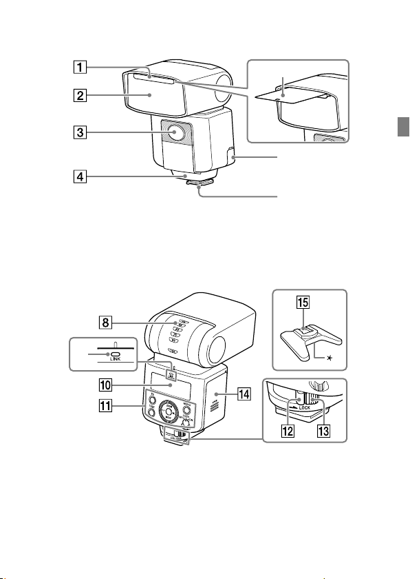
Identifying parts
Built-in wide panel (44)
Flashtube
LED light unit (42) /AF illuminator (49)
Wireless control signal receiver
(for optical wireless communications)
GB
Multi Interface foot (14)
Multi/Micro USB
Terminal
Bounce sheet (48)
Bounce indicator (upper/lower angle) (47)
LINK lamp (35)
LCD panel (11)
Control panel (10)
Lock lever (14)
The number in the parentheses indicates the
page number where you can find the description.
Release button (14)
Battery chamber door
(13)
Mini-stand (32)
* Tripod attachment hole
9
GB
Page 10
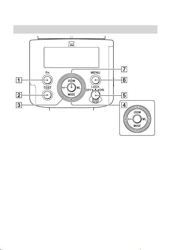
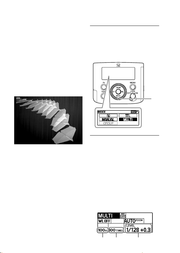
Operation console
Fn button (20)
TEST button (43)
Control wheel
Use the wheel to move the
focus or change the setting item
value on the Quick Navi screen
or the MENU settings screen.
Direction buttons
The number in the parentheses indicates the
page number where you can find the description.
Power switch (15)
Selecting “LOCK” disables
the control wheel and the
buttons on the flash unit and
you can prevent unintentional
operations.
MENU button (22)
Center button
About the LCD backlight
The LCD backlight turns on and stays lit for about 8 seconds every time
you press one of the buttons or use the control wheel on the flash unit.
• While the LCD backlight is lit, you can press one of the buttons or
use the control wheel on the unit to keep it lit longer.
• To turn off the LCD backlight, press the MENU button and select
[BACKLIGHT], and then [OFF].
GB
10
Page 11
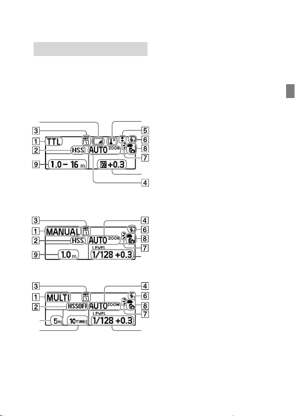
On-screen indicators
The following screen images are
given as examples and may look
different from what you actually
see on the LCD panel.
TTL flash mode
MANUAL flash mode
MULTI flash mode
Flash mode
High-speed sync
Memory Recall
Flash coverage (zoom)
Bounce flash
Ready to fire
Flash distribution setting
Attached to camera
Flash range
Power level
Frequency in multiple flash
Repetition in multiple flash
Wireless channel
Wireless mode
Lighting ratio control setting
Flash compensation
Lighting ratio
Receiver remote setting
Wireless group setting
Flash distribution setting/
Commander/Control unit
flash setting
Low-battery indicator
Overheat indicator
GB
GB
11
Page 12
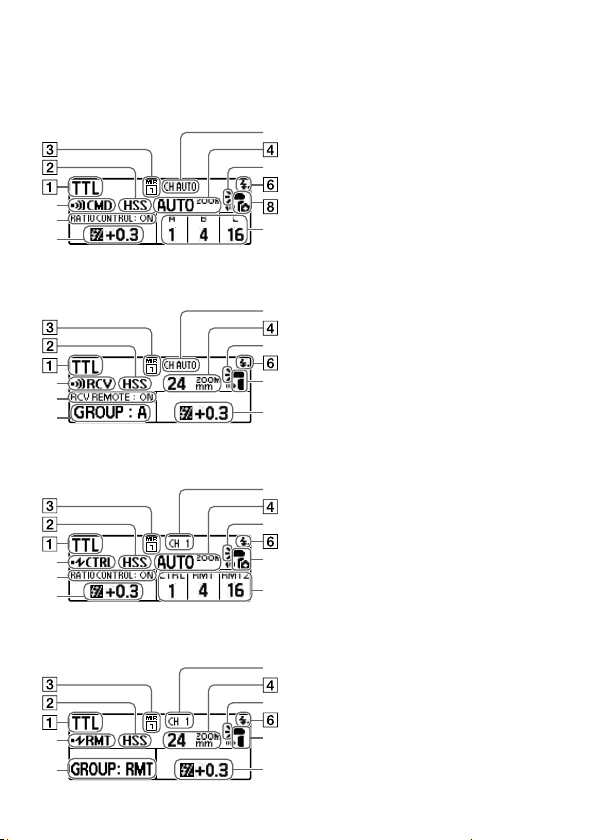
Wireless commander mode
(radio control)
Wireless receiver mode
(radio control)
Wireless controller mode
(optical wireless communications)
Wireless remote mode
(optical wireless communications)
Flash mode
High-speed sync
Memory Recall
Flash coverage (zoom)
Bounce flash
Ready to fire
Flash distribution setting
Attached to camera
Flash range
Power level
Frequency in multiple flash
Repetition in multiple flash
Wireless channel
Wireless mode
Lighting ratio control setting
Flash compensation
Lighting ratio
Receiver remote setting
Wireless group setting
Flash distribution setting/
Commander/Control unit
flash setting
Low-battery indicator
Overheat indicator
GB
12
Page 13
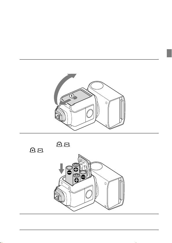
Inserting batteries
The flash unit can accommodate either set of the following:
• Four AA-size alkaline batteries
• Four AA-size rechargeable nickel-metal hydride (Ni-MH) batteries
Before you use the rechargeable nickel-metal hydride batteries, be
sure to fully charge the batteries with the specified battery charger.
No batteries are supplied with the flash unit.
1 Push and slide the battery chamber door in the
direction of the arrow shown below.
2 Insert the batteries into the battery chamber as
illustrated (
(
indicate the direction of the batteries.)
).
GB
3 Close the battery chamber door.
Slide the door in the reverse direction of the arrow in step 1.
13
GB
Page 14
Attaching/removing the flash unit to/from the camera
To attach the flash unit
to the camera
1 Turn off the power of
the flash unit.
If your camera is equipped
with a built-in flash, make
sure that the camera flash is
not released.
2 Remove the terminal
protection cap from
the Multi Interface
foot on the flash unit;
and the shoe cap from
the Multi Interface
shoe on the camera.
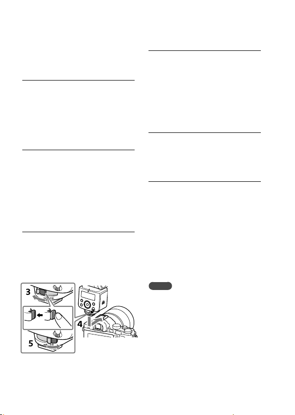
3 Press and hold the
release button and
rotate the lock lever
away from “LOCK.”
4 Insert the Multi
Interface foot of the
flash unit into the
Multi Interface shoe
on the camera and
push in the foot all the
way.
5 Rotate the lock lever
toward “LOCK” to
secure the flash unit
on the camera.
To remove the flash
unit from the camera
Turn off the power of the flash
unit first. Press and hold the
release button, rotate the lock
lever away from “LOCK,” and
then slide the unit out of the
Multi Interface shoe.
Notes
When you do not intend to use
the flash unit, be sure to attach the
terminal protection cap back to the
Multi Interface foot.
GB
14
Page 15
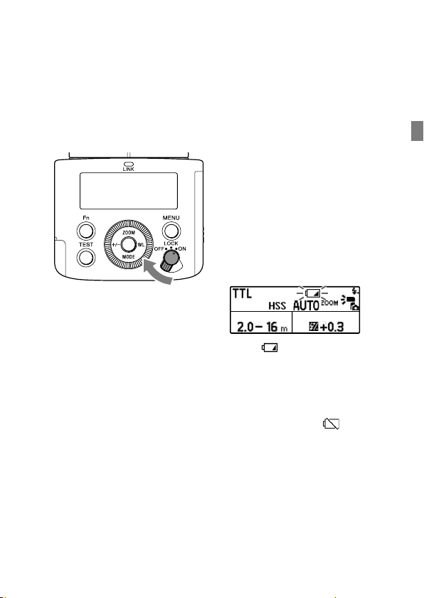
Turning on the power of the flash unit
Turn on the power
switch.
When the flash unit is powered,
on-screen indicators are
displayed on the LCD panel.
Power-saving mode
• If the flash unit is left unused
for 3 minutes while it is used
alone or connected to the
camera in a power-saving
state, the LCD panel will
automatically turn off to
conserve the battery power.
• During wireless flash
photography with the flash
unit used as an off-camera
flash (page 31), the flash
unit goes into power-saving
mode in 60 minutes.
• Turning off the power switch
on the connected camera*
automatically places the flash
unit in power-saving mode.
* Except for DSLR-A100
• You can press the MENU
button and select [POWER
SAVE] to specify the powersaving timer, or select [WL
POWER SAVE] to specify
the power-saving timer for
wireless flash photography.
Checking the
remaining battery
power
When the batteries are running
out of power, the low-battery
indicator is displayed on the LCD
panel as a warning.
When is blinking:
It is recommended that you
replace the batteries. The flash
unit, however, is still capable of
firing in this state.
When nothing but
LCD panel:
The flash unit is not capable of
firing. Replace the batteries.
is on the
15
GB
GB
Page 16

Notes on continuous
flashes
If you use the flash unit
continuously for a short period
of time, its built-in safety circuit
may be triggered to reduce the
flash counts by increasing the
flash frequency.
Also, if the temperature inside
the flash unit rises further,
(overheat indicator) will light
on the LCD panel to indicate
that flash firing is disabled for a
while. In such a case, turn off the
power switch on the flash unit
and leave the unit unused for
about 10 minutes to allow it to
cool down.
Continuous flashes heat up the
batteries inside the flash unit.
Take extra care if you need to
remove the batteries.
GB
16
Page 17
Pairing with a radio wireless commander/receiver (for radio wireless flash photography)
To perform radio wireless flash
photography with this flash
unit, you need another flash
unit that supports radio wireless
communications or a radio
wireless commander/receiver
(not supplied) in addition to this
flash unit and must pair them
both together.
This section describes how to
pair two HVL-F45RM (this flash
unit) units.
For pairing the flash unit with
a radio wireless commander/
receiver (not supplied), refer
to the operating instructions
supplied with the device.
Tips
• You need to bring both devices
within 1 m from each other for
pairing.
• You can pair the flash unit with up
to 15 radio wireless devices.
1 Turn on the power of
this flash unit and the
other device.
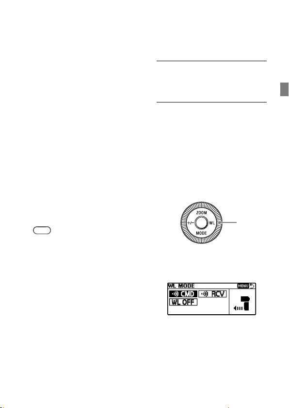
2 Press the WL button
(
) to display the
screen for setting
the wireless mode,
and then specify
one flash unit as the
commander unit
and the other as the
receiver unit.
• To specify a flash unit
as the commander unit,
select [CMD].
GB
17
GB
Page 18
• To specify a flash unit as
the receiver unit, select
[RCV].
Notes
• The above instructions are given
based on the assumption that
this flash unit uses default radio
wireless communications.
This flash unit is capable
of using 2 types of wireless
communications for
wireless flash photography:
radio and optical wireless
communications. For setting
the unit to use optical wireless
communications, see page 31.
• You can press the MENU button
and select [PAIRED DEVICE] to
see the flash unit(s) paired as
the receiver unit(s) or delete the
paired receiver unit(s).
• When you have changed the
setting of the commander unit
and specified it as a receiver
unit, or vice versa, be sure to
reestablish paring among the
units.
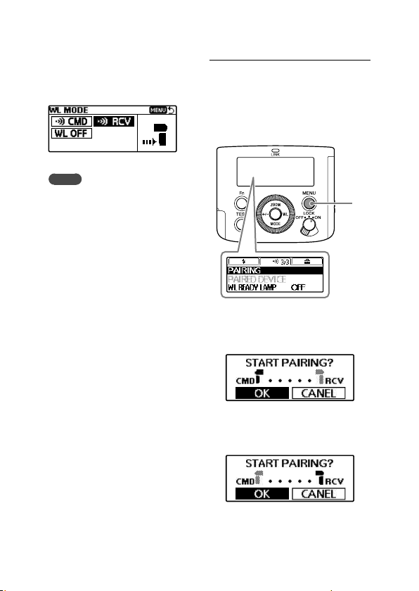
3 On this flash unit
and the other flash
unit, press the MENU
button () and select
[PAIRING].
• On the commander unit,
the following screen is
displayed.
• On the receiver unit,
the following screen is
displayed.
GB
18
Page 19
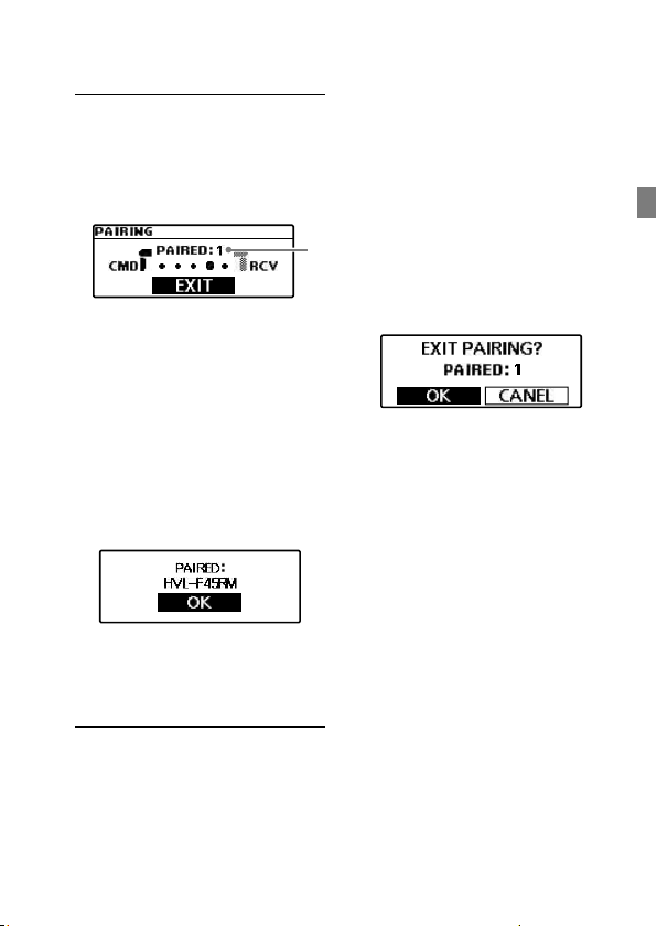
4 Select [OK] to
establish pairing.
• On the commander unit,
the following screen is
displayed.
Pairing is established. On
the commander unit, you
can continue pairing with
other receiver units. Every
time pairing is established
with a receiver unit, the
number of paired devices
() increases.
• On the receiver unit,
the following screen is
displayed.
Pairing is established.
When pairing is established,
the LINK lamp turns from
red to green in color.
To establish a pairing with 2
or more devices
Set each device to be paired
with this flash unit as the
receiver unit and repeat steps
3 and 4.
When you are finished with
pairing with all receiver units,
select [EXIT] on the commander
unit, and then [OK] on the
following screen.
GB
19
GB
Page 20
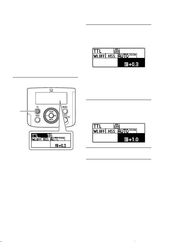
Quick Navi settings
You can press the Fn button
on the flash unit to change the
settings for photography, such
as the selected flash mode, in
accordance with the on-screen
indications.
Select the setting item of choice
and rotate the control wheel to
change the setting option.
1 Press the Fn button ().
2 Select the setting item
of your choice with
the direction buttons.
Pressing the center button
following the above
operation displays the
specific screen for setting
the selected item.
3 Rotate the control
wheel to change the
setting option.
4 Press the Fn button.
GB
20
Page 21
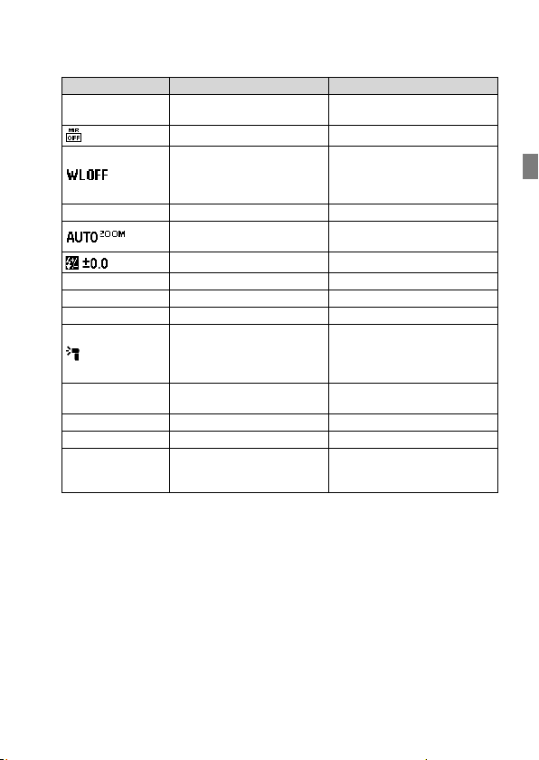
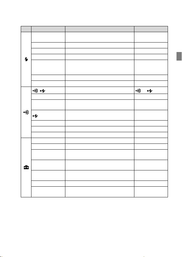
Setting items Descriptions Setting options
TTL Flash mode setting
Memory Recall OFF(*)/MR1/MR2
Wireless mode setting
HSS High-speed sync setting ON(*)/OFF
1/1 Power level setting 1/1 - 1/128, CMD LINK
5Hz Frequency in multiple flash 1 - 100
10TIMES Repetition in multiple flash 2 - 100, --
RATIO CONTROL:
OFF
A B C Power level ratio setting OFF/1(*) - 16
RCV REMOTE: OFF Receiver remote setting ON/OFF(*)
GROUP: A Wireless group setting
* Factory default setting
The items and options available for setting vary depending on the flash mode.
Flash coverage (zoom)
setting
Flash compensation setting -3.0 - +3.0
CMD flash setting (radio
control)
CTRL flash setting (optical
control)
Lighting ratio setting ON/OFF(*)
TTL(*)/MANUAL/MULTI/
flash off/GROUP
WF OFF(*)/CMD/RCV (radio
control)
WF OFF(*)/CTRL/RMT (optical
control)
AUTO(*)/24-105
ON(*)/OFF
OFF/ A(*)/B/C/D/E (radio
control)
RMT(*)/RMT2 (optical control)
GB
21
GB
Page 22
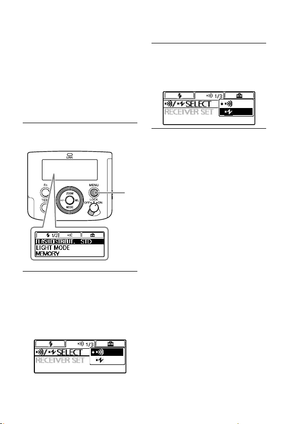
MENU settings
You can press the MENU button
on the flash unit to change the
MENU settings.
Move the focus to the setting
item of your choice with the
direction buttons, and then
press the center button to select
the item.
1 Press the MENU
button ().
2 Move the focus to
the setting item of
your choice with the
direction buttons, and
then press the center
button.
3 Change the setting
option with the
direction buttons and
press the center button.
GB
22
Page 23
Groups
Setting items Descriptions Setting options
FLASH
DISTRIBUT.
LIGHT MODE LED light ON/OFF setting ON/OFF
MEMORY Memory settings MR1/MR2
AF LED LEVEL AF illuminator level setting HIGH(*)/LOW
TEST Test-flash setting
LEVEL STEP Power level setting steps 0.3EV(*)/0.5EV
CUSTOM KEY Custom key settings -
/ SELECT
RECEIVER SET Receiver settings -
CH SET Radio controlled wireless CH setting
CH SET
PAIRING Pairing setting PAIRED DEVICE Paired device display WL READY LAMP Wireless flash ready lamp setting ON/OFF(*)
BACKLIGHT LCD backlight setting AUTO(*)/ON/OFF
m/ft Flash range unit setting m(*)/ft
POWER SAVE Power-saving timer setting
WL POWER SAVE
VERSION
RESET Reset setting for Quick Navi screen -
INITIALIZE
* Factory default setting
Flash distribution setting
Wireless control type setting
Optical controlled wireless CH
setting
Wireless flash power-saving timer
setting
Version display for this product's /
RCV software
Restoring the default settings at
shipment
STD(*)/CENTER/
EVEN
GROUP/1TIME
(*)/
3TIMES/4SEC
AUTO(*)/CH1CH14
CH1(*)-CH4
30SEC/3MIN(*)/
30MIN/OFF
60MIN(*)/
240MIN/OFF
-
-
GB
(*)/
23
GB
Page 24
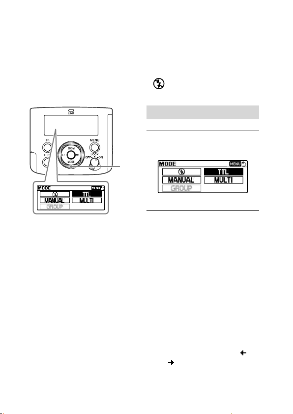
Photographing
Selecting the flash
mode
You can press the MODE button
) and rotate the control wheel
(
to select the flash mode of the
flash unit.
• TTL* flash mode
The flash unit measures
the amount of light coming
through the lens and
automatically adjusts the flash
power level.
* TTL stands for Through The
Lens.
• MANUAL flash mode (page 26)
You need to manually adjust
the flash power level for
keeping it consistent.
• MULTI flash mode (page 28)
You can specify the number of
repetition in multiple flash and
the frequency in multiple flash.
• Group flash mode (page 36)
You can select this flash
mode for radio wireless flash
photography.
Flash off mode
•
Flash firing is disabled.
TTL flash photography
1 Select the flash mode.
Select TTL flash mode.
2 Press the shutter
button to take a photo.
Make sure that the flash unit
is ready to fire before you
press the shutter button.
The orange-lit TEST button
indicates that the flash unit
is ready to fire.
• Take photos within the
indicated flash range.
This flash unit is capable
of indicating distances
within the range from 0.7
m to 28 m. If the distance
is beyond this range,
next to the flash range
indicator will light.
or
GB
24
Page 25

• You can press the +/button to change the flash
compensation (adjust the
flash power level) on the
screen for setting the flash
compensation.
• To use fill-flash or autoflash mode of the camera,
you need to select the
mode on the camera.
• Before photographing with
the flash unit using the
self-timer of the camera,
make sure that the TEST
button is lit.
• If flash compensation is
made both on the flash
unit and the camera, both
compensation values are
added up for flash firing.
On the LCD panel of the
flash unit, however, only
the compensation value
specified on the unit is
displayed.
Auto WB adjustment
with color temperature
information
White balance is automatically
adjusted on the camera (except
for DSLR-A100) based on the
color temperature information at
the time of flash firing.
• This function works when the
flash unit is attached to the
camera and placed in TTL flash
mode.
• This function works when
[Auto] or [Flash] is specified
for the white balance on the
camera.
TTL*-flash mode
Manual-flash mode
provides a fixed flash power
irrespective of the brightness
of the subject and the camera
setting. TTL-flash mode
measures the light from
the subject that is reflected
through the lens.
TTL metering also has a
P-TTL metering function,
which adds a pre-flash to
TTL metering, and an ADI
metering function, which
adds distance data to the
P-TTL metering.
* TTL stands for Through The
Lens.
• ADI metering is possible in
combination with a lens with
a built-in distance encoder.
Before using the ADI metering
function, check whether your
lens has a built-in distance
encoder by referring to the
specifications in the operating
instructions supplied with your
lens.
GB
25
GB
Page 26
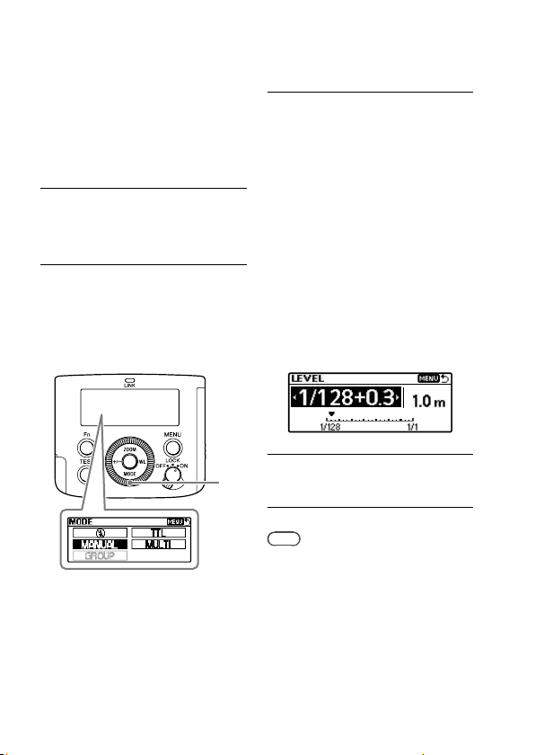
Manual flash photography (MANUAL)
Manual flash mode keeps the
flash power level consistent
regardless of the brightness of
the subject or the settings of the
camera.
1 Select M (Manual)
shooting mode on the
camera.
2 Press the MODE button
(
) to display the
screen for setting the
flash mode, and then
select [MANUAL].
3 Press the +/- button
and specify the flash
power level of your
choice on the screen
for setting the power
level.
• You can specify the flash
power level in the range
from 1/1 (brightest) to
1/128 (darkest).
• Increasing the flash power
by one level (e.g. 1/1
1/2) is equivalent to
increasing the aperture by
one level (e.g. F4
5.6).
4 Press the shutter
button to take a photo.
Tips
• You can press the shutter button
halfway down to display the
distance for the proper exposure on
the LCD panel.
• You can press the MENU button and
select [LEVEL STEP] to change the
power level setting step ([0.3EV] or
[0.5EV]).
GB
26
Page 27
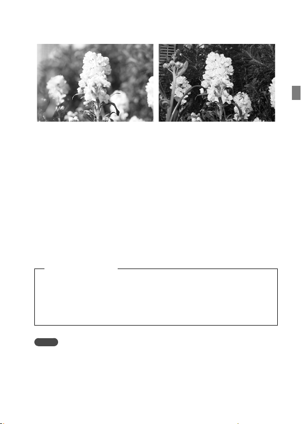
High-speed sync photography (HSS)
High-speed sync photography Normal flash photography
High-speed sync photography eliminates the flash sync speed
restrictions and enables the flash unit to be used through the entire
shutter speed range of the camera. An increase in the selectable
aperture range allows flash photography with a wide aperture,
leaving the background out of focus and accentuating the front
subject. When photographing a scene, where the background is very
bright and the photograph is likely to be over-exposed, at a wide
f-stop in A or M shooting mode of the camera, you can still adjust the
exposure to the proper level by using the high-speed shutter.
To turn off the HSS function, follow the instructions for Quick Navi
settings (page 20) and change the setting option for [HSS] to [OFF].
Flash sync speed
Flash photography is generally associated with the maximum
shutter speed referred to as the flash sync speed. This restriction
does not apply to cameras designed for high-speed sync (HSS)
photography, since they allow flash photography at the maximum
shutter speed of the camera.
GB
Notes
If you set the shutter speed of the camera faster than 1/4000 and take a photo,
bright and dark streaks may appear on the photo.
It is recommended that you set the flash power level to at least MANUAL 1/2 for
photography.
27
GB
Page 28
Multiple flash photography (MULTI)
This flash unit is capable of
firing multiple times while the
camera shutter is open (multiple
flash photography). Multiple
flash photography allows you to
capture a series of movements
of the subject in a single photo.
For multiple flash photography,
you need to place the camera
in M shooting mode. Otherwise,
you may not obtain the proper
exposure.
1 Press the MODE button
(
) to display the
screen for setting the
flash mode, and then
select [MULTI].
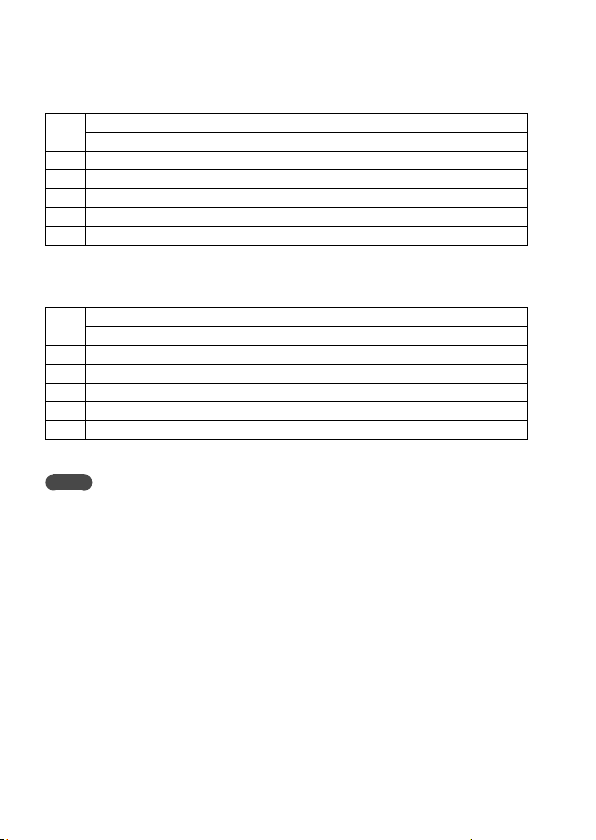
2 Press the Fn button,
select the following
items with the
direction buttons, and
specify the setting
option with the control
wheel.
[Hz]: Frequency in
multiple flash
[TIMES]: Repetition in
multiple flash
[LEVEL]: Power level setting
GB
28
Page 29

• Setting options
[Hz]: 1 Hz - 100 Hz
[TIMES]: 2 - 100, --
[LEVEL]: 1/8 - 1/128
When [TIMES] is set to [--],
the flash unit continuously
fires as many times as
possible with the specified
frequency in multiple flash.
3 Set the shutter speed
and the aperture on
the camera.
The shutter speed should be
at least equal to the number
specified for repetition in
multiple flash (TIMES) divided
by the specified frequency in
multiple flash (Hz).
For example, if the number
for repetition in multiple
flash is specified to “10” and
the frequency in multiple
flash to “5 Hz”, set the
shutter speed of the camera
to at least 2 seconds.
4 Make sure that the flash
unit is ready to fire, and
then press the shutter
button to take a photo.
To avoid blurring of images
due to hand movement, it is
recommended that you use
a tripod for multiple flash
photography.
Maximum number for
repetition in multiple flash
Due to the limited battery
capacity, the maximum numbers
that you can specify for
repetition in multiple flash are
shown in the following tables as
guidelines.
GB
29
GB
Page 30
When using the alkaline batteries
Power
levels
100 90 80 70 60 50 40 30 20 10 9 8 7 6 5 4 3 2 1
1/8
5 5 5 5 5 5 5 5 6 6 6 6 7 7 8 9 10
1/16
8 8 9 9 9 9 10 10 10 15 15 20 20 30 45 65
1/32
15 15 15 15 17 17 18 18 20 40 50 65 80
1/64
30 30 32 32 35 37 40 45 75
1/128
60 60 65 65 70
Flash frequencies (Hz)
100* 100*
100* 100* 100*
100* 100* 100* 100* 100* 100*
100* 100* 100* 100* 100* 100* 100* 100* 100* 100*
100* 100* 100* 100* 100* 100* 100* 100* 100* 100* 100* 100* 100* 100*
“100*” indicates 100 or greater.
When using the nickel-hydride batteries (2100 mAh)
Power
levels
100 90 80 70 60 50 40 30 20 10 9 8 7 6 5 4 3 2 1
1/8
5 5 5 5 5 5 5 6 6 7 7 8 8 10 10 25
1/16
8 8 9 9 9 9 10 10 10 15 20 30 60 75
1/32
17 17 18 18 18 19 20 20 40 80
1/64
32 33 35 36 40 45 55 95
1/128
63 65 70
Notes
The maximum number that you can specify for repetition in multiple flash varies
depending on the type and condition of the batteries.
100* 100* 100* 100* 100* 100* 100* 100* 100* 100* 100* 100* 100* 100* 100* 100*
Flash frequencies (Hz)
100* 100* 100*
100* 100* 100* 100* 100*
100* 100* 100* 100* 100* 100* 100* 100* 100*
100* 100* 100* 100* 100* 100* 100* 100* 100* 100* 100*
“100*” indicates 100 or greater.
GB
30
Page 31

Wireless flash photography (with radio or optical communications)
This flash unit supports 2 types
of wireless communications
for wireless flash photography:
radio and optical wireless
communications.
Radio wireless flash
photography
Wireless flash photography
is available using the radio
communication method. This
helps you photograph with the
flash unit in an environment with
many obstacles.
For radio wireless flash
photography, you need
another flash unit or a wireless
commander/receiver (not
supplied) that supports radio
wireless communications in
addition to this flash unit.
Notes
For radio wireless flash photography,
you need the camera that supports
radio wireless communications.
Refer to the operating instructions
supplied with the camera.
Optical wireless flash
photography
Wireless flash photography
is available using the optical
communication method. This
helps you photograph with the
flash unit in an environment
where radio communications are
not available.
For optical wireless flash
photography, you need another
flash unit that supports optical
wireless communications in
addition to this flash unit.
To switch the wireless
communication method
1 Press the MENU button
() and select [
SELECT] with the
direction buttons.
/
2 Select the wireless
communication
method of your choice.
: Radio wireless
communications with the
flash unit
: Optical wireless
communications with
the flash unit
31
GB
GB
Page 32

Attaching and removing
the mini-stand
When you have removed the
flash unit from the camera
to place and use it alone for
wireless flash photography,
attach the supplied mini-stand
to the unit.
To attach the mini-stand
To remove the mini-stand
Tips
You can screw the mini-stand to a
tripod through the screw hole on the
mini-stand.
Use a tripod with the screw that is
shorter than 5.5 mm in length. To
a tripod with the longer screw, you
cannot secure the mini-stand firmly
with the screw, resulting in possible
damage to the mini-stand.
For instructions on using the
release button and the lock lever,
see page 14.
GB
32
Page 33

Wireless flash photography (with radio wireless communications)
Radio wireless flash
photography
This flash unit supports radio
wireless communications for
flash photography.
Specify [CMD] for the commander
unit attached to the camera;
and [RCV] for the receiver unit
(off-camera flash) of which flash
operation is wirelessly triggered.
Tips
To perform radio wireless flash
photography, you need to establish
paring between the commander unit
and the receiver unit(s) in advance
(page 17).
1 Press the WL button
(
) on this flash unit
and select [CMD] for
the commander unit;
and [RCV] for the
receiver unit.
• To specify the flash unit
as the commander unit,
select [CMD].
GB
• To specify the flash unit
as the receiver unit, select
[RCV].
The radio wireless
communication distance
available between the
commander unit and the receiver
unit is approximately 30 m
(98.4 ft.). (Acquired under our
measurement conditions.)
33
GB
Page 34

Wireless flash
photography (with the
receiver unit)
You can specify another flash
unit attached to the camera or
the radio wireless commander
as the commander unit, and
then use the commander unit to
trigger the flash operation of this
flash unit placed away from the
camera.
2 Press the WL button
on this flash unit and
select [RCV].
3 Press the Fn button
and specify the
wireless group for this
flash unit.
4 Attach the mini-stand
to this flash unit (page
32).
Commander unit (CMD)
HVL-F45RM
As the commander unit, you
can use this flash unit or a radio
wireless commander.
1 Select wireless (WL)
flash mode on the
camera.
For selecting the flash mode
on the camera, refer to
the operating instructions
supplied with the camera.
GB
34
5 Attach another flash
unit specified as [CMD]
(commander unit) to
the camera.
Make sure that [CMD] is
displayed on the LCD panel
of the commander unit.
6 Place the camera and
this flash unit.
Page 35

7 Make sure that the
flash unit on the
camera (commander
unit) and this flash
unit are wirelessly
connected and ready
to fire.
Wirelessly connected: The
LINK lamp is lit in green.
Ready to fire: The TEST
button on the back of the
unit is lit in orange.
In addition, while [ON] is
selected for [WL READY
LAMP] on the MENU settings
screen, the AF illuminator on
the front of the receiver unit
blinks.
Multiple wireless flash
photography with
lighting ratio control
You can perform wireless flash
photography while controlling
the lighting ratio among a
maximum of 3 groups including
the commander unit and 2
groups of off-camera flashes.
Commander unit: HVL-F45RM
(this flash unit) or a radio
wireless commander
Receiver unit (off-camera flash):
HVL-F45RM (this flash unit) or a
wireless receiver
GB
8 Press the shutter
button to take a photo.
To fire a test-flash, press
the TEST button on the
commander unit.
Tips
• On the receiver units, the flash
mode of the commander unit is
applied.
• During manual flash photography,
you can press the Fn button and
specify [CMD LINK] for the power
level setting to allow adjustment on
the commander unit.
Commander unit (CMD)
Wireless receiver
Receiver unit (RCV)
• Press the Fn button on the
commander unit and select
[ON] for [RATIO CONTROL: OFF].
• The commander unit fires as
the flash unit in the A group.
• If you do not want the
commander unit to fire, press
the Fn button and specify
[OFF] for the
setting.
CMD flash
35
GB
Page 36

To set the lighting ratio
of the commander unit
Press the Fn button on this flash
unit and specify the power level
ratio setting for the A, B, and C
groups.
Example: When the flash power
level ratio [4:2:1] is displayed on
the LCD panel, the flash unit in
each group fires with a fraction
of the total flash power: 4/7, 2/7,
and 1/7, respectively.
Multiple wireless flash
photography (group
flash photography)
You can perform wireless flash
photography among a maximum
of 5 groups including the
commander unit and 4 groups of
off-camera flashes. To perform
group flash photography, specify
[GROUP] for the flash mode
setting.
Commander unit: HVL-F45RM
(this flash unit) or a radio
wireless commander
Receiver unit (off-camera flash):
HVL-F45RM (this flash unit) or a
wireless receiver
You can specify [TTL], [MANUAL],
or [OFF] for the flash mode of
the A, B, and C groups. For the D
and E groups, on the other hand,
you can specify either [MANUAL]
or [OFF].
The flash units in the group with
the flash mode specified as [OFF]
do not fire.
To set up for group
flash photography
Press the Fn button on this flash
unit and specify the flash mode
setting, the flash compensation
setting, and the power level
setting for the A, B, C, D, and E
groups on the screen for setting
the group flash mode.
Flash mode setting
Flash compensation/power
level setting
GB
36
Page 37

Changing the settings
of individual receiver
units (RECEIVER SET)
You can press the MENU button
on the commander unit and
specify [RECEIVER SET] to
change the wireless group
setting and the flash coverage
(zoom) setting of individual
receiver units paired with the
commander unit.
Wireless connection status
Wireless group setting
You can select [A], [B], [C], [D],
[E], or [OFF].
Zoom setting
You can change the zoom
setting for the receiver unit.
Notes
To enable the commander unit to
change the settings of individual
receiver units, you need to press the
Fn button on each receiver unit and
select [ON] for [RCV REMOTE].
Notes on wireless
flash photography
with radio wireless
communications
• During photography with
off-camera flashes, P-TTL flash
metering is automatically used
instead of ADI metering.
• You can concurrently use up to
15 receiver units (off-camera
flashes).
• On the commander unit, press
the MENU button, select [CH
SET], and then specify the
channel to be used for radio
wireless communications.
While [AUTO] is selected for
[CH SET], a channel appropriate
for the radio conditions at the
time that you turn on the flash
unit is used.
GB
37
GB
Page 38

Wireless flash photography (with optical wireless communications)
Optical wireless flash
photography
This flash unit supports optical
wireless communications for
flash photography.
Specify [CTRL] for the flash unit
attached to the camera as the
controller unit; and [RMT] for the
off-camera flash of which flash
operation is wirelessly triggered
as the remote unit.
1 Press the WL button
(
) and select [CTRL]
for the controller unit;
and [RMT] for the
remote unit.
• To specify the flash unit as
the controller unit, select
[CTRL].
• To specify the flash unit
as the remote unit, select
[RMT].
Place the controller and remote
units within a 5 m radius of the
subject.
GB
38
Page 39

Wireless flash
photography (with the
remote unit)
You can specify another flash
unit attached to the camera or
the built-in flash of the camera
as the controller unit, and then
use the controller unit to trigger
the flash operation of this flash
unit placed away from the
camera.
Built-in flash
Controller unit (CTRL)
HVL-F45RM
As the controller unit, you can
use the built-in flash of an
A-mount camera or another
flash unit model (HVL-F20M,
HVL-F32M, HVL-F43M, HVL-F60M,
etc.) available for a separate
purchase.
1 Attach this flash unit
to the camera and turn
on the power of both
devices.
2 Select wireless (WL) flash
mode on the camera.
For selecting the flash mode
on the camera, refer to
the operating instructions
supplied with the camera.
3 Remove the flash unit
from the camera (page
14) and attach the
mini-stand to the unit
(page 32).
4 Release the built-in
flash of the camera or
attach another flash
unit to the camera.
• Make sure that [RMT]
is displayed on the LCD
panel of this flash unit.
If [CTRL] is displayed,
press the WL button and
change the setting option
to [RMT].
• Make sure that the flash
unit attached to the
camera is specified as the
controller unit. For details,
refer to the operating
instructions supplied with
the attached flash unit.
GB
5 Place the camera and
this flash unit.
39
GB
Page 40

6 Make sure that the
flash on the camera
(controller unit) and
this flash unit are
ready to fire.
When this flash unit is ready
to fire, the TEST button on
the back of the unit lights
in orange. In addition, while
[ON] is selected for [WL
READY LAMP] on the MENU
settings screen, the AF
illuminator on the front of
the receiver unit blinks.
7 Press the shutter
button to take a photo.
• For firing a test-flash with
the camera flash, refer to
the operating instructions
supplied with the camera.
• If this flash unit does not
fire, change the locations
of the camera, this flash
unit, and the subject; or
point the wireless control
signal receiver of this flash
unit toward the camera.
Multiple wireless flash
photography with
lighting ratio control
You can perform wireless flash
photography while controlling
the lighting ratio among a
maximum of 3 groups including
the controller unit and 2 groups
of off-camera flashes.
Controller unit: HVL-F45RM (this
flash unit)
Remote unit (off-camera flash):
HVL-F45RM (this flash unit)
or another flash unit model
that supports optical wireless
communications
Controller unit (CTRL)
Remote unit (RMT)
Remote unit (RMT2)
• Press the Fn button on the
controller unit and select [ON]
for [RATIO CONTROL: OFF].
• You can classify off-camera
flashes (remote units) into 2
groups (RMT and RMT2). Press
the Fn button on the remote
unit and change its wireless
group setting.
GB
40
Page 41

• If you do not want the
commander unit to fire, press
the Fn button and specify
[OFF] for the
setting.
CMD flash
To set the lighting ratio
of the controller unit
Press the Fn button on this flash
unit and specify the power level
ratio setting for the CTRL, RMT,
and RMT2 units.
Example: When the flash power
level ratio [4:2:1] is displayed on
the LCD panel, the flash unit in
each group fires with a fraction
of the total flash power: 4/7, 2/7,
and 1/7, respectively.
• When the controller unit is in
MANUAL flash mode, it fires
with the specified flash power.
Notes on wireless
flash photography
with optical wireless
communications
• During wireless flash
photography, measurement
with a flash meter or a color
meter is not available because
of the pre-flash of the flash
unit.
• When [AUTO] is specified for
the flash coverage (zoom) of
this flash unit being used as a
remote unit, the flash coverage
is automatically set to 24 mm.
• During photography with
off-camera flashes, P-TTL flash
metering is automatically used
instead of ADI metering.
• You can concurrently use
multiple remote units (offcamera flashes).
• When the remote units (offcamera flashes) are in MANUAL
flash mode, each unit fires with
its own specified flash power.
• All flash units used for wireless
flash photography must share
the same wireless channel
(CH). On this flash unit, you can
specify the wireless channel by
pressing the MENU button and
selecting [
CH SET].
GB
41
GB
Page 42

Illuminating for video shooting (LED light)
You can use the LED light of this
flash unit as a light source for
video shooting. It helps create
natural lights and shadows in an
environment with poor lighting,
such as indoors, to add more 3D
effects to video.
To use the LED light
1 Press the MENU button
() and select [LIGHT
MODE].
2 Press the center
button to turn on the
LED light.
To turn it off, press the
center button once again.
3 Adjust LED brightness
with the control wheel.
• While the LED light of the
flash unit is lit, the flash
mode indicator (
displayed on the camera
(i.e. the camera flash is
disabled).
• Depending on the camera,
lens, and brightness
settings for video
shooting, the proper
white balance may not be
obtained. In such a case,
adjust the balance on the
camera.
• To turn off the LED light,
press the MENU button.
) is not
Notes
Note that the LED beam may
be obstructed by the lens end,
depending on the size of the lens
attached to the camera.
GB
42
Page 43

Firing a test-flash
You can fire a test-flash before you start photographing. If you intend
to use a flash meter for manual flash photography (page 26), be
sure to fire a test-flash.
When the TEST button () lights in orange, press the
TEST button.
• The orange-lit TEST button indicates that the flash unit is ready to
fire.
• The flash power for a test-flash depends on the flash power level
specified for each flash mode. During TTL flash photography, this
flash unit fires at the GN equivalent of 2.
• With the test-flash function, you can preview how the subject
cast shadows (a modeling flash). On this flash unit, you can select
[3TIMES] or [4SEC] (continuous flashes at consistent intervals for
4 seconds) for a modeling flash. To change the test-flash setting
on the flash unit, press the MENU button, select [TEST], and then
change the setting option.
• When [1TIME] or [GROUP] is specified for the test-flash setting, you
can press and hold the TEST button to fire the specified number of
test flashes with the specified flash frequency and power in MULTI
flash mode.
• For radio wireless photography, you can press the test-flash button
on the commander unit to force the receiver unit(s) to fire in
accordance with the test-flash setting on the commander unit.
• If this flash unit is specified as the commander unit for radio
wireless photography, the TEST button will light in orange when all
the flash units, including the receiver units, are ready to fire.
GB
43
GB
Page 44

Selecting the flash coverage (zoom)
Automatic selection of the flash coverage (auto
zoom)
This flash unit automatically selects the appropriate flash coverage
for the focal length of the lens on the attached camera within the
range from 24 mm to 105 mm (auto zoom). You do not need to
manually select the flash coverage most of the time.
When [AUTO] is displayed as the flash coverage (zoom) setting on the
LCD panel, the auto zoom function is enabled.
• If you use a lens with the focal length of less than 24 mm while the
auto zoom function is enabled, [WIDE] will blink on the LCD panel.
In such a case, it is recommended that you use the built-in wide
panel of this flash unit. To use the wide panel, gently pull out the
wide panel along with the bounce sheet, fold down the wide panel
to cover the flashtube, and then push the bounce sheet back into
the flash unit.
• [WIDE] is displayed on the LCD panel.
• When you retract the wide panel, push it back all the way into the
flash unit and make sure that [WIDE] is not displayed on the LCD
panel.
• When you pull out the built-in wide panel, do not apply excessive
force as it may cause damage to the wide panel.
GB
44
Page 45

• When you photograph the 2D subject from its front using a lens
with the focal length of less than 18 mm, the periphery of the
screen may appear slightly darker because of the difference in
intensity of the flash light at the center and periphery of the screen.
• When you use a wide-angle lens with the focal length of less than
15 mm, the periphery of the screen may appear darker.
• The focal length displayed on the LCD panel indicates the
equivalent 35mm-format focal length.
• This flash unit does not support the angle of view of a 16mm F2.8
Fisheye lens.
• Before storing this flash unit in the supplied case, be sure to push
the wide panel and the bounce sheet back into the unit.
Manual selection of the flash coverage (manual
zoom)
You can manually select the flash coverage of the flash unit
regardless of the focal length of the lens in use (manual zoom).
Press the ZOOM button (
direction buttons.
) and select the flash coverage with the
GB
45
GB
Page 46

Flash distribution setting
You can press the MENU button and select [FLASH DISTRIBUT.] to
specify the flash distribution pattern. (The flash distribution setting is
applied to the flash coverage whether it is selected automatically or
manually.)
STD : Flash coverage with standard flash distribution
CENTER :
EVEN :
Notes
Depending on the focal length specified for photography, the periphery of the
screen may appear darker. In such case, change the flash distribution pattern.
GB
46
Flash coverage with priority given to guide numbers
Flash coverage with priority given to wider periphery
Page 47

Bounce flash photography
By directing the flashtube of the
flash unit at the ceiling or a wall
of the room instead of directly at
the subject, you can illuminate
the subject with reflected light,
reducing the intensity of the
shadows and producing a softer
light on the screen.
Tips
High-speed sync is available for
bounce flash photography as well.
1 Tilt up or swivel the
flashtube.
Focal length of
lens
70 mm minimum 30°, 45°
28 mm - 70 mm 60°
28 mm maximum 75°, 90°
Top view
Bounce
angle
2 Press the MODE button
and select [TTL].
3 Press the shutter
button to take a photo.
is displayed on the LCD
panel of the flash unit
to indicate bounce flash
photography.
GB
47
GB
Page 48

Using the bounce
sheet
The bounce sheet creates a
highlight in the subject's eyes
and makes the subject look more
vibrant.
1 Pull out the wide panel
gently.
The bounce sheet is also
pulled out. Push back the
wide panel only.
2 Tilt up the flashtube by
90 degrees.
3 Press the MODE button
and select [TTL].
4 Press the shutter
button to take a photo.
GB
48
Close-up photography
Tilt down the flashtube slightly
when photographing objects
between 0.7 m and 1.0 m from
the camera to ensure accurate
illumination.
1 Tilt down the flashtube
by 8 degrees.
• When photographing the
subject located within 0.7
m, remove the flash unit
from the camera and use it
as an off-camera flash (not
supplied) (page 39), or
use a macro twin flash or a
ring light (not supplied).
• When a lengthy lens is
attached to the camera,
the flash beam may be
obstructed by the lens end.
Page 49

About the AF illuminator
If the brightness or contrast setting of the camera is not sufficient for
photographing the subject, the AF illuminator (LED light) on the front
of the flash unit may light when you press the shutter button halfway
down for auto-focusing. The AF illuminator is provided for aiding
auto-focusing.
• The AF illuminator operates even when [ ] is displayed on the
LCD panel.
• When you want to change the brightness of the AF illuminator, you
can press the MENU button, select [AF LED LEVEL], and then [HIGH]
or [LOW].
• To disable the AF illuminator, use the menu on the camera to turn
it off.
• When the AF illuminator on the flash unit lights, the AF illuminator
on the camera is disabled.
• While the camera is in Continuous AF mode (the camera is focusing
on a moving subject), the AF illuminator does not light.
• If the focal length of the lens is greater than 300 mm, the AF
illuminator may not light. In addition, when the flash unit is
removed from the camera, the AF illuminator does not light.
• Depending on the camera to which the flash unit is attached, the
AF illuminator may not light.
GB
49
GB
Page 50

Assigning the custom keys
You can assign a function of your
choice to some of the controls
on the operation console:
direction buttons, center button,
and control wheel.
1 Press the MENU
button (
[CUSTOM KEY].
Groups
MODE Flash mode setting -
ZOOM Flash coverage (zoom) setting
CMD/CTRL FLASH
FLASH DISTRIBUT. Flash distribution setting HSS High-speed sync setting RATIO CONTROL Lighting ratio setting RATIO VALUE Power level ratio setting MODE(GROUP) Group flash mode setting LIGHT MODE LED light ON/OFF setting RECALL Memory Recall -
MEMORY
WL MODE Wireless mode setting RECEIVER SET Receiver settings GROUP Wireless group setting RCV REMOTE Receiver remote setting -
CH SET
OTHERS
NOT SET No setting
GB
50
Assignable
functions
/LEVEL
CH SET
) and select
Descriptions
Power level setting
Commander/Control unit
flash setting
Memory registration of a
mode/setting value
Radio controlled wireless CH
setting
Optical controlled wireless
CH setting
2 Select the control of
your choice with the
direction buttons.
3 Select the function that
you want to assign.
Wheel and buttons
Wheel Center
Left
RightUpDown
*
*
*
-
-
*
-
-
* *
*Factory default setting
Page 51

Registering/recalling the memory settings
You can register one of the
modes that you frequently use
or a combination of values to
either [MR1] or [MR2].
To register
1 Press the MENU button
and select [MEMORY].
2 Select [MR1] or [MR2].
To recall
1 Press the Fn button
and select the item for
recalling the memory
setting.
2 Select [MR1] or [MR2]
with the control wheel.
• To change the memory
setting, recall and change
the setting, and then
register the setting once
again with [MEMORY].
• If you do not intend to use
the registered memory
setting, select [OFF].
• While the memory setting
is recalled, [RESET] on the
MENU settings screen is
disabled.
GB
51
GB
Page 52

Notes on use
While photographing
• This flash unit generates strong
light, so it should not be used
directly in front of the eyes.
• Do not use the flash 20 times
in a row or in quick succession
in order to prevent heating and
degradation of the camera and
flash unit. (when the power
level is 1/32, 40 times in a row.)
Stop using the flash unit and
cool it for 10 minutes or more,
if the flash is triggered up to
the limit for the number of
times in quick succession.
• During wireless photography,
this flash unit may fire
unexpectedly because the
unit is unable to receive
communication signals from
an off-camera flash due to
its location. In such a case,
change the location of the offcamera flash or the wireless
channel setting.
• Do not put this flash unit with
the camera attached in the
bag, etc. It may result in a
malfunction of this flash unit
or the camera.
• Do not carry this flash unit with
the camera attached. It may
result in a malfunction.
• Do not use the flash near
people when rotating the
flashtube during bounce
GB
52
photography. The flash light
may damage the eyes, or the
hot flashtube may cause a
burn.
• When rotating the flashtube,
be careful not to catch your
fingers in the rotating part. You
may be injured.
• This camera is designed to be
dust and moisture-resistant,
but is not waterproof or
splashproof.
• When closing the battery
chamber door, press it firmly in
while sliding it fully across. Be
careful not to injure yourself
by catching your finger in the
battery chamber door when
closing it.
Batteries
• The battery level displayed
on the LCD panel may be
lower than the actual battery
capacity, due to temperature
and storage conditions. The
displayed battery level may be
restored to the correct value
after the flash has been used a
few times.
• Nickel-metal hydride batteries
can lose power suddenly. If
the low-battery indicator starts
blinking or the flash can no
longer be used while taking
pictures, change or recharge
the batteries.
Page 53

• Do not use lithium-ion
batteries because repeated
flash use makes the batteries
hot and the flash will no longer
fire.
• The flash frequency and
number of flashes provided
by new batteries may vary
from the values shown in the
table, depending on the time
elapsed since manufacture of
the batteries.
• Remove the batteries only
after turning the power off
and waiting several minutes,
when changing the batteries.
The batteries may be hot,
depending on the battery type.
Remove them carefully.
• Remove and store the
batteries when you do not
intend to use the camera for a
long time.
Temperature
• The flash unit may be used
over a temperature range of 0
°C to 40 °C.
• Do not expose the flash unit to
extremely high temperatures
(e.g. in direct sunlight inside a
vehicle) or high humidity.
• To prevent condensation
forming on the flash, place
it in a sealed plastic bag
when bringing it from a cold
environment into a warm
environment. Allow it to reach
room temperature before
removing it from the bag.
• Battery capacity decreases
at colder temperatures.
Keep your camera and spare
batteries in a warm inside
pocket when shooting in cold
weather. The low-battery
indicator may blink even when
there is some power left in
the batteries in cold weather.
Batteries will regain some of
their capacity when warmed to
normal operating temperature.
Maintenance
• Remove this unit from the
camera. Clean the flash with
a dry soft cloth. If the flash
has been in contact with
sand, wiping will damage
the surface, and it should
therefore be cleaned gently
using a blower. In the event
of stubborn stains, use a cloth
lightly moistened with water or
tepid water, and then wipe the
unit clean with a dry soft cloth.
Never use strong solvents,
such as thinner or benzine,
as these damage the surface
finish.
• If fingerprints or debris are
stuck to the lens or flashtube,
we recommend that you
gently remove any debris and
then wipe the lens or flashtube
clean with a soft cloth.
53
GB
GB
Page 54

Specifications
Guide number
Normal flash/STD flash distribution (ISO 100)
Manual flash/35mm-format
Power level
1/1
1/2
1/4
1/8
1/16
1/32
1/64
1/128
APS-C format
Power level
1/1
1/2
1/4
1/8
1/16
1/32
1/64
1/128
15* 24 28 35 50 70 105
13 23 25 26 30 36 45
9.2 16.3 17. 7 18.4 21.2 25.5 31.8
6.5 11.5 12.5 13 15 18 22.5
4.6 8.1 8.8 9.2 10.6 12.7 15.9
3.3 5.8 6.3 6.5 7.5 9 11.3
2.3 4.1 4.4 4.6 5.3 6.4 8
1.6 2.9 3.1 3.3 3.8 4.5 5.6
1.1 2 2.2 2.3 2.7 3.2 4
15* 24 28 35 50 70 105
13 24 26 30 36 41 45
9.2 17 18.4 21.2 25.5 29 31.8
6.5 12 13 15 18 20.5 22.5
4.6 8.5 9.2 10.6 12.7 14.5 15.9
3.3 6 6.5 7. 5 9 10.3 11.3
2.3 4.2 4.6 5.3 6.4 7. 2 8
1.6 3 3.3 3.8 4.5 5.1 5.6
1.1 2.1 2.3 2.7 3.2 3.6 4
Flash coverage setting (mm)
* When the wide panel is attached.
Flash coverage setting (mm)
* When the wide panel is attached.
GB
54
Page 55

HSS flat flash/STD flash distribution (ISO 100)
Manual flash/35mm-format
Shutter
speed
1/250
1/500
1/1000
1/2000
1/4000
1/8000
1/16000
15* 24 28 35 50 70 105
4.6 8.4 9.1 9.5 11.3 12.9 16
3.2 5.9 6.4 6.7 8 9.1 11.3
2.3 4.2 4.6 4.8 5.7 6.4 8
1.6 3 3.2 3.4 4 4.6 5.7
1.1 2.1 2.3 2.4 2.8 3.2 4
0.8 1.5 1.6 1.7 2 2.3 2.8
0.6 1 1.1 1.2 1.4 1.6 2
Flash coverage setting (mm)
* When the wide panel is attached.
APS-C format
Shutter
speed
1/250
1/500
1/1000
1/2000
1/4000
1/8000
1/16000
15* 24 28 35 50 70 105
4.6 8.7 9.5 11.3 12.9 15.3 16
3.2 6.2 6.7 8 9.1 10.8 11.3
2.3 4.4 4.8 5.7 6.4 7. 7 8
1.6 3.1 3.4 4 4.6 5.4 5.7
1.1 2.2 2.4 2.8 3.2 3.8 4
0.8 1.5 1.7 2 2.3 2.7 2.8
0.6 1.1 1.2 1.4 1.6 1.9 2
Flash coverage setting (mm)
* When the wide panel is attached.
GB
55
GB
Page 56

Radio wireless features:
Frequency band: 2.4 GHz
Number of channels: 14 channels
Communication distance: Approximately 30 m (98.4 ft.) (Acquired
under our measurement conditions.)
• The distance given above applies under conditions where there are
no obstacles, shielding, or radio wave interferences.
• The communication distance may be shorter depending on the
positioning of the products, the ambient environment, and weather
conditions.
Frequency/Repetition
Frequency (sec) Approx. 0.1 - 2.5 Approx. 0.1 - 2.0
Repetition (times) Approx. 210 or more Approx. 270 or more
• Repetition is the approximate number of times that are
possible before new batteries are completely dead.
Flash control Flash control using pre-flash (P-TTL/ADI)
Continuous flash
performance
AF illuminator Autoflash at low contrast and low brightness
40 flashes at 10 flashes per second
(Normal flash, power level 1/32, 105 mm, nickelmetal hydride battery)
Operating range (While a 50mm lens with the
aperture set at F5.6 is attached and [AF LED LEVEL]
of the flash unit is specified as [HIGH])
Central area (Approx.): 0.5 m to 6 m (1 ft. 7 3/4 in. to
19 ft. 8 1/4 in.)
Peripheral areas (Approx.): 0.5 m to 3 m (1 ft. 7 3/4
in. to 9 ft. 10 1/8 in.)
Alkaline Nickel hydride
GB
56
Page 57

LED light Center luminance intensity: Approx. 400 lx at 0.5 m
Operating
temperature
Storage
temperature
Dimension
(Approx.)
Mass (Approx.) 317 g (11.2 oz) (excluding the batteries)
Power
requirements
Recommended
batteries
Included items Flash unit (1), Connector protect cap (1), Mini-stand
Functions in these operating instructions depend on testing
conditions at our firm.
Design and specifications are subject to change without notice.
(1 ft. 7 3/4 in.) or approx. 100 lx at 1 m (3 ft. 3 3/8 in.)
Lighting distance: Approx. 1 m (3 ft. 3 3/8 in.)
(when recording movies, set to ISO 3200 & F5.6)
Focal length supported: 35 mm (35mm-format
angle of view)
Continuous lighting time: Approx. 4 hours (using
AA alkaline batteries, at center luminance intensity)
Color temperature: Approx. 5,500K
0 °C to 40 °C (32 °F to 104 °F)
–20 °C to +60 °C (–4 °F to +140 °F)
69.4 mm × 113.7 mm × 88.3 mm (2 3/4 in. × 4 1/2 in.
× 3 1/2 in.) (w/h/d)
DC 6 V
Four LR6 (AA-size) alkaline batteries
Four AA-size rechargeable nickel-metal hydride
batteries
(stored in the carrying case) (1), Carrying case (1),
Set of printed documentation
The number in the parentheses indicates the
quantity.
Trademarks
“Multi Interface Shoe” is a trademark of Sony Corporation.
GB
57
GB
Page 58

Français
Avant d’utiliser le produit,
lisez attentivement le présent
manuel et conservez-le pour
consultation ultérieure.
AVERTISSEMENT
Pour réduire les risques
d’incendie ou d’électrocution,
1) n’exposez l’appareil à la pluie
ou à l’humidité ;
2) ne placez pas d’objets remplis
de liquides (vases, etc.) sur
l’appareil.
N’exposez pas les piles à une
chaleur excessive, notamment
aux rayons directs du soleil, à
une flamme, etc.
Lors de l’émission de l’éclair,
le tube à éclairs peut être très
chaud. Ne pas la toucher.
ATTENTION
Remplacez la pile uniquement
par une pile correspondant au
type spécifié. Sinon vous risquez
de provoquer des brûlures, un
incendie ou des blessures.
Avis
Si l’électricité statique ou
les champs électrostatiques
entraînent une interruption
lors du transfert des données
(échec), redémarrez l’application
ou débranchez, puis rebranchez
le câble de connexion (USB, etc.).
Cet appareil a été testé et jugé
conforme aux limites établies
par la réglementation EMC
visant l’utilisation de câbles de
connexion de moins de 3 mètres
(9,8 pi.).
Cet équipement est conforme
aux limites d’exposition aux
rayonnements énoncées pour
un environnement non contrôlé
et respecte les règles les
radioélectriques (RF) de la FCC
lignes directrices d’exposition
et d’exposition aux fréquences
radioélectriques (RF) CNR-102
de l’IC. Cet équipement émet
une énergie RF très faible qui est
considérée comme conforme
sans évaluation du débit
d’absorption spécifique (DAS).
Mettez les piles au rebut
conformément aux instructions.
FR
2
Page 59

Pour les utilisateurs
au Canada
Le présent appareil est conforme
aux CNR d’Industrie Canada
applicables aux appareils radio
exempts de licence.
L’exploitation est autorisée aux
deux conditions suivantes :
1) l’appareil ne doit pas produire
de brouillage;
2) l’utilisateur de l’appareil
doit accepter tout brouillage
radioélect rique subi, même
si le brouillage est susceptible
d’en compromettre le
fonctionnement.
POUR LES CLIENTS
RÉSIDANT EN EUROPE
Fabricant : Sony Corporation,
1-7-1 Konan Minato-ku Tokyo,
108-0075 Japon
Pour toute question relative à
la conformité des produits dans
l’UE : Sony Belgium, bijkantoor
van Sony Europe Limited, Da
Vincilaan 7-D1, 1935 Zaventem,
Belgique
Par la présente, Sony Corporation
déclare que cet appareil est
conforme aux exigences
essentielles et aux autres
dispositions pertinentes de la
directive 1999/5/CE. Pour toute
information complémentaire,
veuillez consulter l’URL suivante :
http://www.compliance.sony.de/
Traitement des
appareils électriques
et électroniques en fin
de vie (Applicable dans les
pays de l’Union Européenne
et aux autres pays européens
disposant de systèmes de
collecte sélective)
Ce symbole, apposé sur le
produit ou sur son emballage,
indique que ce produit ne doit
pas être traité avec les déchets
ménagers. Il doit être remis à un
point de collecte approprié pour
le recyclage des équipements
électriques et électroniques.
En vous assurant que ce
produit sont mis au rebut
de façon appropriée, vous
participez activement à la
prévention des conséquences
negatives que leur mauvais
traitement pourrait provoquer
sur l’environnement et sur la
santé humaine. Le recyclage
des matériaux contribue par
ailleurs à la préservation des
ressources naturelles. Pour toute
information complémentaire au
sujet du recyclage de ce produit,
vous pouvez contacter votre
municipalité, votre déchetterie
locale ou le point de vente où
vous avez acheté le produit.
3
FR
FR
Page 60

Table des matières
Avant la première utilisation ......................................................5
Identification des pièces ............................................................7
Préparations ............................................................................11
Mise en place des piles .............................................................11
Pose/dépose de l'unité flash sur/de l'appareil photo ............12
Mise sous tension de l'unité flash ............................................ 13
Jumelage avec un récepteur/unité de commande radio sans fil
(pour les prises de vue à flash radio sans fil) ...........................15
Réglages ...................................................................................18
Paramètres Quick Navi .............................................................18
Paramètres MENU .................................................................... 20
Prises de vue ..........................................................................22
Prises de vue .............................................................................22
Prises de vue avec flash manuel (MANUAL) ............................24
Prises de vue en mode de synchronisation à grande vitesse (HSS) ....25
Prises de vue à éclairs multiples (MULTI) .................................26
Prises de vue avec flash sans fil
(avec des communications radio ou optiques) .......................29
Prises de vue avec flash sans fil
(avec des communications radio sans fil) ................................ 31
Prises de vue avec flash sans fil
(avec des communications optiques sans fil) ..........................36
Illumination pour l'enregistrement de vidéos (éclairage à LED) ..... 40
Exécution d'un flash test .......................................................... 41
Sélection de la couverture du flash (zoom) .............................42
Prises de vue avec flash réfléchi ............................................. 45
À propos de l'illuminateur AF ...................................................47
Attribution des touches personnalisées ................................. 48
Enregistrement/rappel des paramètres en mémoire ............ 50
Divers.......................................................................................... 51
Remarques sur l’emploi ............................................................ 51
Spécifications ............................................................................53
FR
4
Page 61

Avant la première utilisation
Ce flash peut être utilisé avec les appareils photo à objectif
interchangeable Sony, les caméscopes numériques HD à objectif
interchangeable Sony et les appareils photo numériques Sony
pourvus d’une griffe multi-interface classique.
Selon le modèle d’appareil photo ou de caméscope utilisé certaines
fonctions peuvent ne pas agir.
Pour le détail sur les modèles d’appareils photo compatibles avec ce
flash, consulter le site Sony approprié, ou s’adresser à un revendeur
Sony ou à un service après-vente agréé Sony.
Reportez-vous au mode d’emploi de cet appareil et à celui de votre
appareil photo.
Gardez le tube à éclairs propre. La surface d'un tube à éclairs
sale risque de causer une surchauffe, entraînant l'émanation de
fumées ou des brûlures. Pour nettoyer le tube à éclairs, essuyez-le
avec un chiffon doux, etc.
Cette unité flash est été fabriquée pour se protéger contre les
infiltrations mais elle n'a pas été testée pour cela et elle n'est pas
considérée comme étanche. N'utilisez pas cette unité par temps
de pluie.
Remarques concernant l'utilisation continue du
flash
Pendant une prise de vue à éclairs multiples avec l'unité flash,
avec plusieurs flashs et de mannequins, l'unité flash se déclenche
continuellement.
Ces éclairs continus, ainsi que leurs réflexions sur les murs, peuvent
entraîner une certaine gêne, telle qu'une sensation de vertige, chez
les personnes dont les yeux sont sensibles à la lumière. Si c'est le cas,
arrêtez immédiatement d'utiliser l'unité flash.
FR
FR
5
Page 62

Ne pas placer cette unité flash aux endroits
suivants
Que ce soit pendant son utilisation ou son stockage, ne pas placer
cette unité flash dans les endroits suivants. Cela pourrait entraîner un
dysfonctionnement.
• Placer cette unité flash dans des endroits soumis à la lumière directe du soleil,
comme sur un tableau de bord ou à proximité d’un radiateur, peut entraîner
sa déformation ou son dysfonctionnement.
• Endroits soumis à des vibrations excessives
• Endroits soumis à de fortes ondes magnétiques
• Endroits sablonneux
Prendre garde à ne pas exposer cette unité au sable ou à la poussière lorsque
l’on se trouve sur une plage, dans des zones sablonneuses ou dans des zones
où des nuages de poussière peuvent se former.
Cela pourrait entraîner un dysfonctionnement.
Distance des communications
La distance des communications radio sans fil disponible entre l'unité
flash et l'appareil photo est d'environ 30 m (98,4 pi). (Calculée selon
nos conditions de mesure.)
• La distance donnée ci-dessus est valable en l’absence d’obstacle, de blindage
et d’interférences radioélectriques.
• La distance de communication peut être réduite en fonction de la position du
produit, du milieu environnant et des conditions météorologiques.
Mettez à jour le logiciel de votre appareil photo avant utilisation.
Pour toute information sur la compatibilité de votre appareil,
consultez le site d’assistance dédié.
http://www.sony.net/flash/f45rm/
FR
6
Page 63

Identification des pièces
Adaptateur grand angle intégré (42)
Tube à éclairs
Éclairage à LED (40) /Illuminateur AF (47)
Récepteur de signaux sans cordon
(pour les communications optiques sans fil)
Sabot multi-interface (12)
Multi/micro connecteur
USB
Feuille de réflexion (46)
Indicateur d’orientation (angle vertical) (45)
Témoin LINK (33)
Écran LCD (9)
Panneau de commande (8)
Bouton de verrouillage (12)
Le nombre entre parenthèses indique le numéro de page de la description de l'élément.
Bouton de libération (12)
Volet-couvercle du
compartiment des piles (11)
Mini-support (30)
* Douille de trépied
7
FR
FR
Page 64

Console de commande
Touche Fn (18)
Touche TEST (41)
Molette de commande
Utilisez la molette pour déplacer
la mise au point ou modifier la
valeur d'un paramètre à l'écran
Quick Navi ou MENU.
Touches direction
Le nombre entre parenthèses indique le numéro de page de la description de l'élément.
Interrupteur d’alimentation (13)
La sélection de « LOCK » désactive
la molette de commande et les
touches de l'unité flash pour
éviter l'exécution involontaire
d'une commande.
Bouton MENU (20)
Bouton central
À propos du rétroéclairage LCD
Le rétroéclairage LCD s'allume fixement pendant environ huit
secondes chaque fois que vous appuyez sur l'une des touches ou que
vous utilisez la molette de commande de l'unité flash.
• Lorsque le rétroéclairage LCD est allumé, vous pouvez appuyer sur
l'une des touches ou utiliser la molette de commande de l'unité
pour prolonger son activation.
• Pour éteindre le rétroéclairage LCD, appuyez sur le bouton MENU et
sélectionnez [BACKLIGHT], puis [OFF].
FR
8
Page 65

Indicateurs à l'écran
Les illustrations ci-dessous sont
présentées en tant qu'exemples;
votre écran LCD peut être
différent.
Mode flash TTL
Mode flash MANUAL
Mode flash MULTI
Mode flash
Synchronisation à grande
vitesse
Rappel mémoire
Couverture du flash (zoom)
Flash réfléchi
Prêt à se déclencher
Paramètre de distribution du
flash
Installé sur l'appareil photo
Portée du flash
Puissance
Fréquence des éclairs multiples
Répétition des éclairs multiples
Canal sans fil
Mode sans fil
Paramètre du contrôle de
l'éclairage
Correction d'exposition au
flash
Éclairage
Paramètre distant du récepteur
Paramètre de groupe sans fil
Paramètre de distribution du
flash/unité de commande/
Paramètre de flash de l'unité
de commande
Témoin de faible charge des
piles
Témoin de surchauffe
FR
FR
9
Page 66

Mode unité de commande
sans fil (contrôle radio)
Mode récepteur sans fil
(contrôle radio)
Mode contrôleur sans fil
(communications optiques sans fil)
Mode à distance sans fil
(communications optiques sans fil)
FR
10
Mode flash
Synchronisation à grande
vitesse
Rappel mémoire
Couverture du flash (zoom)
Flash réfléchi
Prêt à se déclencher
Paramètre de distribution du
flash
Installé sur l'appareil photo
Portée du flash
Puissance
Fréquence des éclairs multiples
Répétition des éclairs multiples
Canal sans fil
Mode sans fil
Paramètre du contrôle de
l'éclairage
Correction d'exposition au
flash
Éclairage
Paramètre distant du récepteur
Paramètre de groupe sans fil
Paramètre de distribution du
flash/unité de commande/
Paramètre de flash de l'unité
de commande
Témoin de faible charge des
piles
Témoin de surchauffe
Page 67

Mise en place des piles
Vous pouvez installer dans l'unité flash les piles suivantes :
• Quatre piles alcalines (AA)
• Quatre piles nickel-métal hydrure (Ni-MH) rechargeables (AA)
Avant d'installer les piles nickel-métal hydrure rechargeables,
assurez-vous de les charger complètement à l'aide du chargeur de
piles indiqué. Les piles ne sont pas fournies avec l'unité flash.
1 Poussez et faites glisser le volet-couvercle du
compartiment des piles vers le sens de la flèche
indiquée ci-dessous.
2 Insérez les piles dans le compartiment des piles
comme illustré (
(
indique le sens des piles.)
).
FR
3
Fermez le volet-couvercle du compartiment des piles.
Faites glisser le volet dans le sens opposé de la flèche indiquée à
l'étape 1.
FR
11
Page 68

Pose/dépose de l'unité flash sur/ de l'appareil photo
Pose de l'unité flash
sur l'appareil photo
1 Mettez l'unité flash
hors tension.
Si votre appareil photo est doté
d'un flash intégré, assurez-vous
qu'il n'est pas libéré.
2 Retirez le capuchon de
protection du sabot
multi-interface de
l'unité flash, puis le
capuchon de la griffe
multi-interface de
l'appareil photo.
3 Appuyez de manière
prolongée sur le
bouton de libération
puis placez le bouton
de verrouillage hors
de la position « LOCK ».
4 Introduisez le sabot
multi-interface de
l'unité flash dans la
griffe multi-interface
de l'appareil photo,
puis poussez le sabot
à fond.
5 Placez le bouton de
verrouillage sur la
position « LOCK » pour
fixer correctement
l'unité flash sur
l'appareil photo.
Dépose de l'unité flash
de l'appareil photo
Mettez d'abord l'unité flash hors
tension. Appuyez de manière
prolongée sur le bouton de
libération, placez le bouton de
verrouillage hors de la position «
LOCK », puis retirez l'unité de la
griffe multi-interface.
Remarques
Si vous n'envisagez pas d'utiliser
l'unité flash, assurez-vous de
remettre le capuchon de protection
sur le sabot multi-interface.
FR
12
Page 69

Mise sous tension de l'unité flash
Allumez l'interrupteur
d’alimentation.
À la mise sous tension de l'unité
flash, les indicateurs s'allument
sur l'écran LCD.
Mode de veille
• Si l'unité flash est inutilisée
pendant trois minutes en
mode autonome ou en
mode de veille lorsqu'elle
est installée sur l'appareil
photo, l'écran LCD s'éteint
automatiquement pour
économiser la charge des
piles.
• Lors d'une prise de vue avec
flash sans fil en utilisant l'unité
flash à distance (page 29),
l'unité flash passe en mode de
veille après 60 minutes.
• La mise hors tension
de l'appareil photo* fait
automatiquement passer
l'unité flash en mode de veille.
* À l'exception du DSLR-A100
• Appuyez sur le bouton MENU
puis sélectionnez [POWER
SAVE] afin d'indiquer la
minuterie du mode de veille,
ou sélectionnez [WL POWER
SAVE] afin d'indiquer la
minuterie du mode de veille
lors de la prise de vue avec un
flash sans fil.
Vérification de
l'autonomie des piles
Lorsque les piles sont presque
déchargées, le témoin de faible
charge des piles s'allume sur
l'écran LCD pour vous avertir de
la situation.
Lorsque clignote :
Il est conseillé de remplacer les
piles. Toutefois, l'unité flash peut
toujours fonctionner dans cet
état.
Lorsque
sur l'écran LCD :
L'unité flash ne peut plus
fonctionner. Remplacez les piles.
est le seul indicateur
FR
13
FR
Page 70

Remarques concernant
l'utilisation continue du
flash
Si vous utilisez l'unité flash
continuellement pendant une
durée courte, son circuit de
sécurité intégré risque de se
déclencher afin de réduire le
nombre d'éclairs en augmentant
la fréquence d'éclair.
En outre, si la température
à l'intérieur de l'unité flash
augmente toujours,
de surchauffe) s'allume sur
l'écran LCD pour signaler que
le déclenchement du flash
a été interrompu. Dans ce
cas, éteignez l'interrupteur
d'alimentation de l'unité flash
et laissez-la refroidir pendant
environ dix minutes.
Les éclairs continus font chauffer
les piles installées dans l'unité
flash. Faites attention lorsque
vous devez retirer les piles.
(témoin
FR
14
Page 71

Jumelage avec un récepteur/unité de commande radio sans fil (pour les prises de vue à flash radio sans fil)
Pour les prises de vue à flash
radio sans fil avec l'unité flash,
vous devez utiliser une autre
unité flash qui prend en charge
les communications sans fil
ou un(e) récepteur/unité de
commande radio sans fil (non
fourni(e)) qui doit être jumelé(e)
avec cette unité flash.
Cette section présente le
jumelage de deux unités
HVL-F45RM (cette unité flash).
Pour jumeler l'unité flash
avec un récepteur/unité de
commande radio sans fil (non
fourni(e)), reportez-vous au
mode d'emploi fourni avec
l'appareil.
Conseils
• Pour le jumelage, les deux
appareils doivent se trouver à
moins d'un mètre.
• Vous pouvez jumeler l'unité flash
avec jusqu'à 15 appareils radio
sans fil.
1 Mettez l'unité flash et
l'autre appareil sous
tension.
2 Appuyez sur le bouton
WL (
) pour afficher
l'écran de réglage du
mode sans fil, puis
indiquez une unité
flash en tant qu'unité
de commande et
l'autre en tant qu'unité
de réception.
• Pour indiquer une unité
flash en tant qu'unité de
commande, sélectionnez
[CMD].
FR
15
FR
Page 72

• Pour indiquer une unité
flash en tant qu'unité de
réception, sélectionnez
[RCV].
Remarques
• Les instructions ci-dessus
assument que cette unité flash
utilise les communications radio
sans fil par défaut. Cette unité
flash peut utiliser deux types
de communications sans fil
pour les prises de vue à flash
sans fil, les communications
optiques et radio sans fil. Pour
configurer l'unité à utiliser les
communications optiques sans
fil, reportez-vous à la page 29.
• Appuyez sur le bouton MENU
puis sélectionnez [PAIRED
DEVICE] pour afficher la ou les
unités flash jumelées en tant
qu'unité(s) de réception ou pour
supprimer la ou les unités de
réception jumelées.
• Lorsque vous modifiez le
réglage de l'unité de commande
et la faites passer en tant
qu'unité de réception, ou vice et
versa, assurez-vous de rétablir le
jumelage entre les unités.
3 Sur cette unité flash
et l'autre unité
flash, appuyez sur
le bouton MENU ()
puis sélectionnez
[PAIRING].
• Sur l'unité de commande,
l'écran ci-dessous
s'affiche.
• Sur l'unité de réception,
l'écran ci-dessous
s'affiche.
FR
16
Page 73

4 Sélectionnez [OK] pour
réaliser le jumelage.
• Sur l'unité de commande,
l'écran ci-dessous
s'affiche.
Le jumelage est réalisé.
Sur l'unité de commande,
vous pouvez continuer le
jumelage avec d'autres
unités de réception. Chaque
fois que le jumelage est
réalisé avec une unité
de réception, le nombre
d'appareils jumelés ()
augmente.
• Sur l'unité de réception,
l'écran ci-dessous
s'affiche.
Le jumelage est réalisé.
Lorsque le jumelage est
réalisé, le témoin LINK passe
du rouge au vert.
Jumelage de plusieurs
appareils
Configurez chaque appareil à
jumeler avec cette unité flash
comme unité de réception et
recommencez les étapes 3 et 4.
Lorsque le jumelage de toutes
les unités de réception est
terminé, sélectionnez [EXIT] sur
l'unité de commande, puis [OK]
dans l'écran ci-dessous.
FR
17
FR
Page 74

Paramètres Quick Navi
Appuyez sur la touche Fn de
l'unité flash pour modifier
les paramètres de la prise de
vue, tels que le mode flash
sélectionné, en fonction des
indications affichées à l'écran.
Sélectionnez l'élément de
paramètre de votre choix puis
faites tourner la molette de
commande pour modifier
l'option.
1 Appuyez sur la touche
Fn ().
2 Sélectionnez l'élément
de paramètre de votre
choix avec les touches
de direction.
Si vous appuyez sur le
bouton central après cette
opération, l'écran spécifique
pour le réglage de l'élément
sélectionné s'affiche.
3 Tournez la molette
de commande pour
modifier l'option de
paramètre.
4 Appuyez sur la touche
Fn.
FR
18
Page 75

Éléments de
paramètre
TTL Paramètre du mode flash
HSS
1/1 Paramètre de la puissance 1/1 - 1/128, CMD LINK
5Hz
10TIMES
RATIO CONTROL:
OFF
A B C
RCV REMOTE: OFF
GROUP: A
* Paramètre par défaut établi en usine
Les éléments et options disponibles pour le réglage varient selon le mode flash.
Descriptions Options de paramètre
TTL(*)/MANUAL/MULTI/
flash éteint/GROUP
Rappel mémoire OFF(*)/MR1/MR2
WF OFF(*)/CMD/RCV
Paramètre du mode sans fil
Paramètre de la synchronisation
à grande vitesse
Paramètre de la couverture
du flash (zoom)
Paramètre de la correction
d'exposition au flash
Fréquence des éclairs multiples
Répétition des éclairs multiples
Paramètre de flash CMD
(contrôle radio)
Paramètre de flash CTRL
(contrôle optique)
Paramètre d'éclairage ON/OFF(*)
Paramètre du taux de puissance
Paramètre distant du récepteur
Paramètre de groupe sans fil
(contrôle radio)
WF OFF(*)/CTRL/RMT (optical
control)
ON(*)/OFF
AUTO(*)/24-105
-3.0 - +3.0
1 - 100
2 - 100, --
ON(*)/OFF
OFF/1(*) - 16
ON/OFF(*)
OFF/ A(*)/B/C/D/E (contrôle radio)
RMT(*)/RMT2 (contrôle optique)
FR
19
FR
Page 76

Paramètres MENU
Appuyez sur le bouton MENU
de l'unité flash pour modifier les
paramètres MENU.
Mettez en surbrillance l'élément
de paramètre de votre choix à
l'aide des touches direction, puis
appuyez sur le bouton central
pour sélectionner l'élément.
1 Appuyez sur le bouton
MENU ().
2 Mettez en surbrillance
l'élément de paramètre
de votre choix à l'aide
des touches direction,
puis appuyez sur le
bouton central.
3 Modifiez l'option de
paramètre à l'aide des
touches direction puis
appuyez sur le bouton
central.
FR
20
Page 77

Éléments de
Groupes
paramètre
FLASH
DISTRIBUT.
LIGHT MODE
MEMORY Paramètres de mémoire MR1/MR2
AF LED LEVEL
TEST Paramètre de flash test
LEVEL STEP Étapes du paramètre de puissance 0.3EV(*)/0.5EV
CUSTOM KEY
/ SELECT
RECEIVER SET Paramètres du récepteur -
CH SET
CH SET
PAIRING Paramètre de jumelage PAIRED DEVICE Affiche les appareils jumelés -
WL READY LAMP
BACKLIGHT Paramètre du rétroéclairage LCD AUTO(*)/ON/OFF
m/ft
POWER SAVE Paramètre de la minuterie de veille
WL POWER SAVE
VERSION
RESET
INITIALIZE
* Paramètre par défaut établi en usine
Paramètre de distribution du flash
Paramètre ON/OFF de l'éclairage
à LED
Paramètre du niveau de
l'illuminateur AF
Paramètres des touches
personnalisées
Paramètre du type de commande
sans fil
Paramètre CH sans fil commandé
par radio
Paramètre CH sans fil commandé
par optiques
Paramètre du témoin de flash sans
fil prêt
Paramètre de l'unité de portée du flash
Paramètre de la minuterie de veille
du flash sans fil
Version du logiciel de ce produit/
RCV
Réinitialise le réglage de l'écran
Quick Navi
Restaure les paramètres par défaut
établis à l'usine
Descriptions
STD(*)/CENTER/
EVEN
ON/OFF
HIGH(*)/LOW
GROUP/1TIME
(*)/
3TIMES/4SEC
-
AUTO(*)/CH1CH14
CH1(*)-CH4
ON/OFF(*)
m(*)/ft
30SEC/3MIN(*)/
30MIN/OFF
60MIN(*)/
240MIN/OFF
-
-
-
Options de
paramètre
(*)/
FR
21
FR
Page 78

Prises de vue
Sélection du mode
flash
Appuyez sur la touche MODE
) puis tournez la molette de
(
commande pour sélectionner le
mode flash de cette unité.
• Mode flash TTL*
L'unité flash calcule la quantité
de lumière passant dans l'objectif
et règle automatiquement la
puissance du flash.
* TTL signifie en anglais
(Through The Lens).
• Mode flash MANUAL (page 24)
Vous devez régler manuellement
la puissance du flash pour qu'elle
soit régulière.
Mode flash MULTI (page 26)
•
Vous pouvez indiquer le
nombre de répétitions et la
fréquence des éclairs multiples.
• Mode flash Group (page 34)
Vous pouvez sélectionner ce
mode flash pour les prises de
FR
22
vue à flashs radio sans fil.
• Mode flash désactivé
Le déclenchement du flash est
désactivé.
Prises de vue avec
flash TTL
1 Sélectionnez le mode
flash.
Sélectionnez le mode flash TTL.
2
Appuyez sur le
déclencheur pour
prendre une photo.
Assurez-vous que l'unité
flash est prête à se
déclencher avant d'appuyer
sur le déclencheur.
La touche TEST devient
orange pour indiquer que
l'unité flash est prête à se
déclencher.
• Prenez des photos dans la
portée de flash indiquée.
Cette unité flash peut
indiquer une portée de
0,7m à 28 m. Si la distance
est supérieure à cette
portée,
en regard de l'indicateur
de portée du flash.
ou s'allume
Page 79

• Vous pouvez appuyer
sur la touche +/- pour
modifier la correction
d'exposition au flash
(réglage de la puissance
du flash) à l'écran.
• Pour utiliser le mode
Fill-flash ou Auto-flash
de l'appareil photo, vous
devez sélectionner le
mode sur l'appareil photo.
• Avant de prendre des
photos avec l'unité flash
à l'aide du retardateur de
l'appareil photo, assurezvous que la touche TEST
est allumée.
• Si la correction d'exposition
au flash est effectuée sur
l'unité flash et sur l'appareil
photo, les deux valeurs de
correction s'ajoutent lors
de la production de l'éclair.
Toutefois, sur l'écran LCD de
l'unité flash, seule la valeur
de correction indiquée sur
l'unité s'affiche.
Réglage automatique
de la balance des
blancs avec les
informations sur la
température de couleur
La balance des blancs est
automatiquement corrigée sur
l'appareil photo (sauf pour le
DSLR-A100) en fonction des
informations de la température
de couleur au moment du
déclenchement du flash.
• Cette fonction fonctionne
lorsque l'unité flash est installée
sur l'appareil photo et qu'elle se
trouve en mode flash TTL.
• Cette fonction fonctionne
lorsque la balance des blancs
[Auto] ou [Flash] est indiquée
sur l'appareil photo.
Mode flash TTL*
En mode flash manuel,
l’intensité de l’éclair est fixe
quels que soient la luminosité
du sujet et le réglage de
l’appareil photo. Le mode
flash TTL mesure la lumière
du sujet qui est réfléchie dans
l’objectif. Le flashmètre TTL
dispose également d’une
fonction de mesure P-TTL
qui ajoute un pré-flash à la
mesure TTL, ainsi qu’une
fonction de mesure ADI
qui ajoute des données de
distance à la mesure P-TTL.
* TTL = par l’objectif
• Il est possible de combiner la
mesure ADI avec un objectif
équipé d’un encodeur de
distance intégré. Avant
d’utiliser la fonction de mesure
ADI, vérifiez si l’objectif est
équipé d’un encodeur de
distance intégré en consultant
les spécifications du mode
d’emploi fourni avec l’objectif.
FR
23
FR
Page 80

Prises de vue avec flash manuel (MANUAL)
Le mode flash manuel permet
d'obtenir une puissance de
flash régulière quels que soient
la luminosité du sujet ou les
paramètres de l'appareil photo.
1 Sélectionnez le mode
de prise de vue M
(Manuel) sur l'appareil
photo.
2 Appuyez sur la touche
MODE (
afficher l'écran de
réglage du mode flash,
puis sélectionnez
[MANUAL].
) pour
3 Appuyez sur la touche
+/- et indiquez la
puissance de flash de
votre choix sur l'écran
de réglage de la
puissance.
• Vous pouvez indiquer une
puissance de flash de 1/1
(la plus lumineuse) à 1/128
(la moins lumineuse).
• Une augmentation de la
puissance de flash d'un
cran (par exemple de 1/1 à
1/2) équivaut à augmenter
l'ouverture d'un cran (par
exemple de F4 à 5.6).
4 Appuyez sur le
déclencheur pour
prendre une photo.
Conseils
• Appuyez sur le déclencheur à
mi-course pour afficher la distance
pour une exposition correcte sur
l'écran LCD.
• Appuyez sur le bouton MENU et
sélectionnez [LEVEL STEP] pour
modifier le niveau de puissance
([0.3EV] ou [0.5EV]).
FR
24
Page 81

Prises de vue en mode de synchronisation à grande vitesse (HSS)
FR
Prise de vue en mode de
synchronisation à grande vitesse
La synchro haute vitesse permet de s’affranchir des restrictions
habituelles de la synchro classique et d’accéder à l’ensemble de la
gamme de vitesses d’obturation de l’appareil lors de l’utilisation du
flash. La gamme d’ouvertures compatibles augmente, ce qui permet
des prises de vue avec une large ouverture de diaphragme : la mise
au point sur l’arrière plan est floue, mettant ainsi en valeur le sujet
du premier plan. Même lors d’une prise de vue à une ouverture de
diaphragme géométrique élevée en mode A ou M, lorsque l’arrièreplan est très lumineux et que la prise est normalement surexposée,
il est possible de régler l’exposition en utilisant le déclencheur haute
vitesse.
Pour désactiver la fonction HSS, suivez les instructions pour les
paramètres Quick Navi (page 18) et réglez l'option de paramètre
[HSS] sur [OFF].
Prise de vue avec flash normal
Vitesse de synchro du flash
Les photographies réalisées avec le flash sont généralement
associées à une vitesse d’obturation maximale appelée vitesse de
synchro du flash. Cette restriction ne s’applique pas aux appareils
photo conçus pour la photographie de synchro haute vitesse
(HSS), car ils permettent de photographier au flash à la vitesse
d’obturation maximale de l’appareil.
Remarques
Si vous réglez une vitesse d'obturation de l'appareil photo supérieure à
1/4000 et que vous prenez une photo, des bandes claires et sombres risquent
d'apparaître sur la photo.
Il est conseillé de régler la puissance du flash à au moins MANUAL 1/2 pour la
prise de vue.
25
FR
Page 82

Prises de vue à éclairs multiples (MULTI)
Cette unité flash peut se
déclencher plusieurs fois
pendant l'ouverture de
l'obturation de l'appareil photo
(prise de vue à éclairs multiples).
La prise de vue à éclairs
multiples permet de capturer
une série de mouvements du
sujet sur une seule photo.
Pour la prise de vue à éclairs
multiples, vous devez placer
l'appareil photo en mode M.
Sinon, vous ne pourrez pas
obtenir l'exposition correcte.
1
Appuyez sur la touche
MODE () pour afficher
l'écran de réglage
du mode flash, puis
sélectionnez [MULTI].
2 Appuyez sur la touche
Fn, sélectionnez les
éléments suivants
à l'aide des touches
direction, puis
indiquez l'option de
paramètre avec la
molette de commande.
[Hz] : fréquence des
éclairs multiples
[TIMES] : répétition des
éclairs multiples
[LEVEL] : paramètre de la
puissance
FR
26
Page 83

• Options de paramètre
[Hz] : 1 Hz - 100 Hz
[TIMES] : 2 - 100, --
[LEVEL] : 1/8 - 1/128
Si [TIMES] est réglé sur [--],
l'unité flash se déclenche
continuellement autant de
fois que possible selon la
fréquence indiquée dans les
éclairs multiples.
3 Réglez une vitesse
d'obturation et
l'ouverture sur
l'appareil photo.
La vitesse d'obturation doit
être supérieure ou égale
au nombre indiqué pour
la répétition des éclairs
multiples (TIMES) divisé
par la fréquence des éclairs
multiples indiquée (Hz).
Par exemple, si le nombre
de répétitions des éclairs
multiples est « 10 » et la
fréquence des éclairs
multiples « 5 Hz », réglez
la vitesse d'obturation de
l'appareil photo à au moins
deux secondes.
4 Assurez-vous que
l'unité flash est prête
à se déclencher
avant d'appuyer sur
le déclencheur pour
prendre une photo.
Pour éviter des images
floues en raison du
tremblement de vos mains,
il est conseillé d'utiliser un
trépied pour les prises de
vue à éclairs multiples.
Nombre maximal de
la répétition des éclairs
multiples
En raison de l'autonomie
limitée des piles, les nombres
maximums de répétitions des
éclairs multiples que vous
pouvez indiquer sont présentés
dans les tableaux ci-dessous en
guise de référence.
FR
27
FR
Page 84

Avec des piles alcalines
Puissance
100 90 80 70 60 50 40 30 20 10 9 8 7 6 5 4 3 2 1
1/8
5 5 5 5 5 5 5 5 6 6 6 6 7 7 8 9 10
1/16
8 8 9 9 9 9 10 10 10 15 15 20 20 30 45 65
1/32
15 15 15 15 17 17 18 18 20 40 50 65 80
1/64
30 30 32 32 35 37 40 45 75
1/128
60 60 65 65 70
Fréquences du flash (Hz)
100* 100* 100* 100* 100* 100*
100* 100* 100* 100* 100* 100* 100* 100* 100* 100*
100* 100* 100* 100* 100* 100* 100* 100* 100* 100* 100* 100* 100* 100*
« 100* » indique 100 ou plus.
Avec des piles nickel-métal hydrure (2100 mAh)
Puissance
100 90 80 70 60 50 40 30 20 10 9 8 7 6 5 4 3 2 1
1/8
5 5 5 5 5 5 5 6 6 7 7 8 8 10 10 25
1/16
8 8 9 9 9 9 10 10 10 15 20 30 60 75
1/32
17 17 18 18 18 19 20 20 40 80
1/64
32 33 35 36 40 45 55 95
1/128
63 65 70
Remarques
Le nombre maximal de répétition des éclairs multiples que vous pouvez
indiquer varie selon le type et l'état des piles.
100* 100* 100* 100* 100* 100* 100* 100* 100* 100* 100* 100* 100* 100* 100* 100*
Fréquences du flash (Hz)
100* 100* 100* 100* 100*
100* 100* 100* 100* 100* 100* 100* 100* 100*
100* 100* 100* 100* 100* 100* 100* 100* 100* 100* 100*
« 100* » indique 100 ou plus.
100* 100*
100* 100* 100*
100* 100* 100*
FR
28
Page 85

Prises de vue avec flash sans fil (avec des communications radio ou optiques)
Cette unité flash prend en charge
deux types de communications
sans fil pour les prises de vue à
flash sans fil, les communications
optiques et radio sans fil.
Prises de vue avec flash
radio sans fil
Les prises de vue avec flash
sans fil sont disponibles avec
la méthode de communication
radio. Elle vous aide à
photographier avec l'unité flash
dans un environnement où se
trouvent de nombreux obstacles.
Pour les prises de vue avec
flash radio sans fil, une autre
unité flash ou une unité de
commande/récepteur sans fil
(non fourni) prenant en charge
les communications radio sans
fil est nécessaire en plus de cette
unité flash.
Remarques
Pour les prises de vue avec flash radio
sans fil, l'appareil photo doit prendre
en charge les communications radio
sans fil.
Reportez-vous au mode d'emploi
fourni avec l'appareil photo.
Prises de vue avec flash
optique sans fil
Les prises de vue avec flash
sans fil sont disponibles avec
la méthode de communication
optique. Elle vous aide à
photographier avec l'unité flash
dans un environnement où les
communications radio ne sont
pas disponibles.
Pour les prises de vue avec flash
optique sans fil, une autre unité
flash prenant en charge les
communications optiques sans
fil est nécessaire en plus de cette
unité flash.
Changement de méthode de
communication sans fil
1 Appuyez sur le bouton
MENU () puis
sélectionnez [ /
SELECT] ] à l'aide des
touches direction.
2
Sélectionnez la méthode
de communication sans
fil de votre choix.
: communications radio
sans fil avec l'unité flash
: communications
optiques sans fil avec
l'unité flash
29
FR
FR
Page 86

Pose et dépose du
mini-support
Lorsque vous avez retiré l'unité
flash de l'appareil photo pour
l'utiliser en mode autonome
pour des prises de vue avec flash
sans fil, installez le mini-support
fourni sur l'unité.
Pose du mini-support
Dépose du mini-support
Conseils
Vous pouvez visser le mini-support à
un trépied à travers l'orifice de vis du
mini-support.
Utilisez un trépied dont la longueur
de la vis est inférieure à 5,5 mm. Si
cette longueur est supérieure, vous
ne pourrez pas fixer correctement
le mini-support à l'aide de la vis, ce
qui risque d'endommager le minisupport.
Pour des instructions sur
l'utilisation du bouton de
libération et du bouton de
verrouillage, reportez-vous à la
page 12.
FR
30
Page 87

Prises de vue avec flash sans fil (avec des communications radio sans fil)
Prises de vue avec
flash radio sans fil
Cette unité flash prend en charge
des communications radio sans
fil pour les prises de vue avec
flash.
Choisissez [CMD] pour l'unité de
commande reliée à l'appareil
photo, et [RCV] pour l'unité
de réception (flash non fixé à
l'appareil photo) pour laquelle
le fonctionnement du flash sera
déclenché à distance.
Conseils
Pour les prises de vue en mode flash
radio sans fil, vous devez réaliser au
préalable un jumelage entre l'unité
de commande et la ou les unités de
réception (page 15).
1 Appuyez sur la touche
WL (
) de l'unité
flash et sélectionnez
[CMD] pour l'unité
de commande et
[RCV] pour l'unité de
réception.
• Pour régler l'unité
flash comme unité de
commande, sélectionnez
[CMD].
FR
• Pour régler l'unité flash
comme unité de réception,
sélectionnez [RCV].
La distance des communications
radio sans fil disponible entre
l'unité de commande et l'unité
de réception est d'environ 30m
(98,4 pi). (Calculée selon nos
conditions de mesure.)
31
FR
Page 88

Prises de vue avec
flash sans fil (avec
l'unité de réception)
Vous pouvez indiquer une autre
unité flash fixée à l'appareil
photo ou l'unité de commande
radio sans fil en tant qu'unité de
commande pour déclencher à
distance le flash de cette unité.
Unité de commande (CMD)
HVL-F45RM
En tant qu'unité de commande,
vous pouvez utiliser cette unité
flash ou une unité de commande
radio sans fil.
1 Sélectionnez le mode
flash sans fil (WL) sur
l'appareil photo.
Pour sélectionner le mode
flash sur l'appareil photo,
reportez-vous au mode
d'emploi fourni avec
l'appareil photo.
2 Appuyez sur la touche
WL de l'unité flash puis
sélectionnez [RCV].
3 Appuyez sur la touche
Fn puis indiquez le
groupe sans fil de
cette unité flash.
4 Installez le mini-
support sur cette unité
flash (page 30).
5 Installez une autre
unité flash choisie en
tant que [CMD] (unité
de commande) sur
l'appareil photo.
Assurez-vous que [CMD]
s'affiche à l'écran LCD de
l'unité de commande.
6 Posez l'appareil photo
et cette unité flash.
FR
32
Page 89

7 Assurez-vous que
l'unité flash sur
l'appareil photo (unité
de commande) et
cette unité flash sont
jumelées à distance
(sans fil) et sont prêtes
à fonctionner.
Connecté(e) à distance : Le
témoin LINK s'allume en vert.
Prêt à se déclencher : La
touche TEST à l'arrière de
l'unité s'allume en orange.
En outre, lorsque [ON]
est sélectionné pour [WL
READY LAMP] dans le menu
des paramètres MENU,
l'illuminateur AF à l'avant de
l'unité de réception clignote.
8 Appuyez sur le
déclencheur pour
prendre une photo.
Pour déclencher un flash test,
appuyez sur la touche TEST
de l'unité de commande.
Conseils
• Sur les unités de réception, le mode
flash de l'unité de commande est
appliqué.
• Pendant les prises de vue en mode
flash normal, vous pouvez appuyer
sur la touche Fn et indiquez un
paramètre de puissance [CMD
LINK] pour permettre le réglage sur
l'unité de commande.
Prises de vue à éclairs
multiples sans fil avec
contrôle de l'éclairage
Vous pouvez faire des prises de
vue avec flash sans fil tout en
contrôlant l'éclairage de trois
groupes au maximum, y compris
l'unité de commande et deux
groupes de flashs à distance
(éloignés de l'appareil photo).
Unité de commande : HVL-F45RM
(cette unité flash) ou une unité
de commande radio sans fil
Unité de réception (distante de
l'appareil photo) : HVL-F45RM
(cette unité flash) ou un
récepteur sans fil
Unité de commande (CMD)
Récepteur sans fil
Unité de réception (RCV)
• Appuyez sur la touche Fn
de l'unité de commande et
sélectionnez [ON] pour [RATIO
CONTROL: OFF].
• L'unité de commande sera
l'unité flash du groupe A.
• Si vous voulez désactiver
l'unité de commande, appuyez
sur la touche Fn et choisissez
[OFF] pour le paramètre de
flash
CMD.
FR
33
FR
Page 90

Réglage de l'éclairage
de l'unité de commande
Appuyez sur la touche Fn de
cette unité flash, puis indiquez
le paramètre de puissance des
groupes A, B et C.
Exemple : Lorsque la puissance
de flash [4:2:1] s'affiche sur
l'écran LCD, l'unité flash de
chaque groupe utilisera une
fraction de la puissance totale :
4/7, 2/7 et 1/7, respectivement.
Prises de vue à éclairs
multiples sans fil
(flash par groupe)
Vous pouvez faire des prises de
vue avec flash sans fil avec cinq
groupes au maximum, y compris
l'unité de commande et quatre
groupes de flashs à distance
(éloignés de l'appareil photo).
Pour effectuer des prises de vue
par groupe de flashs, indiquez
le paramètre de mode flash
[GROUP].
Unité de commande :
HVL-F45RM (cette unité flash) ou
une unité de commande radio
sans fil
Unité de réception (distante de
l'appareil photo) : HVL-F45RM
(cette unité flash) ou un
récepteur sans fil
Vous pouvez sélectionner le
mode flash [TTL], [MANUAL] ou
[OFF] pour les groupes A, B et C.
Par contre, pour les groupes D et
E, vous ne pouvez sélectionner
que [MANUAL] ou [OFF].
Les unités flash d'un groupe
dont le mode [OFF] a été
sélectionné ne se déclencheront
pas.
Réglage des prises de
vue avec groupe de
flashs
Appuyez sur la touche Fn de
cette unité flash et sélectionnez
les paramètres de mode flash,
de la correction d'exposition au
flash et de puissance pour les
groupes A, B, C, D et E sur l'écran
afin de configurer le mode de
groupe de flashs.
Paramètre de mode flash
Paramètre de la correction
d'exposition au flash/
puissance
FR
34
Page 91

Modification des
paramètres d'unités de
réception individuelles
(RECEIVER SET)
Appuyez sur le bouton MENU
de l'unité de commande et
indiquez [RECEIVER SET] pour
modifier le paramètre de groupe
sans fil et la couverture du flash
(zoom) des unités de réception
individuelles, jumelées avec
l'unité de commande.
État de la connexion sans fil
Paramètre de groupe sans fil
Vous pouvez sélectionner [A],
[B], [C], [D], [E] ou [OFF].
Paramètre de zoom
Vous pouvez modifier le
paramètre de zoom de l'unité
de réception.
Remarques
Pour activer l'unité de commande afin
de changer les paramètres des unités
de réception individuelles, vous devez
appuyer sur la touche Fn de chaque
unité puis sélectionner [ON] pour [RCV
REMOTE].
Remarques concernant
les prises de vue avec
flash sans fil (avec des
communications radio
sans fil)
• Pendant les prises de vue
avec des flashs à distance,
le flashmètre P-TTL est
automatiquement utilisé au
lieu du système ADI.
• Vous pouvez utiliser
simultanément jusqu'à
15unités de réception
(distantes de l'appareil photo).
• Sur l'unité de commande,
appuyez sur le bouton MENU,
sélectionnez [CH SET], puis
indiquez le canal à utiliser
pour les communications radio
sans fil.
Lorsque [AUTO] est sélectionné
pour [CH SET], un canal
approprié aux conditions radio
au moment de la mise sous
tension de l'unité flash est
utilisé.
FR
35
FR
Page 92

Prises de vue avec flash sans fil (avec des communications optiques sans fil)
Prises de vue avec
flash optique sans fil
Cette unité flash prend en charge
les communications optiques
sans fil pour des prises de vue
avec flash.
Indiquez [CTRL] pour l'unité flash
installée sur l'appareil photo
comme contrôleur ; et [RMT]
pour le flash distant dont le
fonctionnement sera déclenché
sans fil comme unité distante.
1 Appuyez sur la touche
WL (
) et sélectionnez
[CTRL] pour le
contrôleur et [RMT]
pour l'unité distante.
• Pour indiquer l'unité
flash comme contrôleur,
sélectionnez [CTRL].
• Pour indiquer l'unité flash
comme unité distante,
sélectionnez [RMT].
Placez le contrôleur et l'unité
distante dans un périmètre
inférieur à 5 m du sujet.
FR
36
Page 93

Prises de vue avec
flash sans fil (avec
l'unité distante)
Vous pouvez indiquer une
autre unité flash installée sur
l'appareil photo ou le flash
intégré de l'appareil photo en
tant que contrôleur et utiliser ce
dernier pour déclencher depuis
l'appareil photo le flash distant
(appelé également flash esclave
ou asservi).
Flash intégré
Contrôleur (CTRL)
HVL-F45RM
En ce qui concerne le contrôleur,
vous pouvez utiliser le flash
intégré d'un appareil photo à
monture A ou un autre modèle
d'unité flash (HVL-F20M,
HVL-F32M, HVL-F43M, HVL-F60M,
etc.) vendu séparément.
1 Fixez cette unité flash
sur l'appareil photo
puis mettez les deux
appareils sous tension.
2 Sélectionnez le mode
flash sans fil (WL) sur
l'appareil photo.
Pour sélectionner le mode
flash sur l'appareil photo,
reportez-vous au mode
d'emploi fourni avec
l'appareil photo.
3 Retirez l'unité flash de
l'appareil photo (page
12) et installez
le mini-support sur
l'unité (page 30).
4 Libérez le flash intégré
de l'appareil photo
ou installez une
autre unité flash sur
l'appareil photo.
• Assurez-vous que [RMT]
s'affiche à l'écran LCD de
cette unité flash. Si [CTRL]
s'affiche, appuyez sur la
touche WL et définissez
l'option de paramètre sur
[RMT].
• Assurez-vous que l'unité
flash installée sur l'appareil
photo est indiquée comme
contrôleur. Pour plus
d'informations, reportezvous au mode d'emploi de
l'unité flash installée.
5 Posez l'appareil photo
et cette unité flash.
FR
37
FR
Page 94

6 Assurez-vous que le
flash sur l'appareil
photo (contrôleur) et
cette unité flash sont
prêts à fonctionner.
Lorsque cette unité flash
est prête à fonctionner, la
touche TEST à l'arrière de
l'unité s'allume en orange.
En outre, lorsque [ON]
est sélectionné pour [WL
READY LAMP] dans le menu
des paramètres MENU,
l'illuminateur AF à l'avant de
l'unité de réception clignote.
7 Appuyez sur le
déclencheur pour
prendre une photo.
• Pour effectuer un flash test
avec le flash de l'appareil
photo, reportez-vous au
mode d'emploi fourni avec
l'appareil photo.
• Si cette unité flash ne
fonctionne pas, modifiez
l'emplacement de
l'appareil photo, de cette
unité flash et du sujet ;
ou dirigez le récepteur de
signaux sans fil de cette
unité flash vers l'appareil
photo.
Prises de vue à éclairs
multiples sans fil avec
contrôle de l'éclairage
Vous pouvez faire des prises de
vue avec flash sans fil tout en
contrôlant l'éclairage de trois
groupes au maximum, y compris
le contrôleur et deux groupes
de flashs à distance (éloignés de
l'appareil photo).
Contrôleur : HVL-F45RM (cette
unité flash)
Unité distante (éloignée de
l'appareil photo) : HVL-F45RM
(cette unité flash) ou un autre
modèle d'unité flash qui prend
en charge les communications
optiques sans fil
Contrôleur (CTRL)
Unité distante (RMT)
Unité distante (RMT2)
• Appuyez sur la touche Fn du
contrôleur et sélectionnez [ON]
pour [RATIO CONTROL: OFF].
• Vous pouvez classer les flashs
distants (unités distantes) en
deux groupes (RMT et RMT2).
Appuyez sur la touche Fn de
l'unité distante et modifiez son
paramètre de groupe sans fil.
FR
38
Page 95

• Si vous ne voulez pas
déclencher l'unité de
commande, appuyez sur la
touche Fn et choisissez [OFF]
pour le paramètre de flash
CMD.
Réglage de l'éclairage
du contrôleur
Appuyez sur la touche Fn de
cette unité flash, puis indiquez
le paramètre de puissance des
groupes CTRL, RMT et RMT2.
Exemple : lorsque la puissance
de flash [4:2:1] s'affiche sur
l'écran LCD, l'unité flash de
chaque groupe utilisera une
fraction de la puissance totale :
4/7, 2/7 et 1/7, respectivement.
• Lorsque le contrôleur est en
mode flash MANUAL, il utilise
la puissance de flash indiquée.
Remarques concernant
les prises de vue avec
flash sans fil (avec
des communications
optiques sans fil)
• Pendant les prises de vue
avec flash sans fil, les mesures
effectuées avec un flashmètre
ou un thermocolorimètre ne
sont pas disponibles en raison
du préflash de l'unité flash.
• Lorsque [AUTO] est indiquée
pour la couverture du flash
(zoom) de cette unité flash
utilisée en tant qu'unité
distante, la couverture du flash
est automatiquement définie
sur 24 mm.
• Pendant les prises de vue
avec des flashs à distance,
le flashmètre P-TTL est
automatiquement utilisé au
lieu du système ADI.
• Vous pouvez utiliser
simultanément plusieurs
unités distantes (éloignées de
l'appareil photo).
• Lorsque les unités distantes
(éloignées de l'appareil photo)
sont en mode flash MANUAL,
chaque unité utilise la puissance
de flash qui lui a été indiquée.
• Toutes les unités flash utilisées
pour la prise de vue avec flash
sans fil doivent partager le
même canal sans fil (CH). Sur
cette unité flash, vous pouvez
indiquer le canal sans fil en
appuyant sur le bouton MENU
et en sélectionnant [
SET].
FR
CH
39
FR
Page 96

Illumination pour l'enregistrement de vidéos (éclairage à LED)
Vous pouvez utiliser l'éclairage
à LED de cette unité flash
comme source de lumière lors
de l'enregistrement d'une vidéo.
Il permet de créer un éclairage
naturel dans un environnement
qui n'est pas très bien éclairé, tel
que dans une pièce, pour ajouter
plus d'effets 3D à la vidéo.
Utilisation de
l'éclairage à LED
1 Appuyez sur le bouton
MENU () puis
sélectionnez [LIGHT
MODE].
2 Appuyez sur le bouton
central pour allumer
l'éclairage à LED.
Pour éteindre l'éclairage,
appuyez une nouvelle fois
sur le bouton central.
3 Réglez la luminosité
LED à l'aide de la
molette de commande.
• Pendant que l'éclairage
à LED de l'unité flash est
allumé, l'indicateur du mode
) ne s'affiche pas sur
flash (
l'appareil photo (c.-à-d. que
le flash de l'appareil photo
est désactivé).
• Selon l'objectif, l'appareil
photo et les paramètres
de luminosité utilisés lors
de l'enregistrement de
vidéos, il peut être difficile
d'obtenir une balance des
blancs adéquate. Dans ce
cas, réglez la balance sur
l'appareil photo.
• Pour éteindre l'éclairage à
LED, appuyez sur le bouton
MENU.
Remarques
Le faisceau LED peut être obstrué par
l'extrémité de l'objectif, selon la taille
de l'objectif installé sur l'appareil photo.
FR
40
Page 97

Exécution d'un flash test
Vous pouvez exécuter un flash test avant vos prises de vue. Si vous
envisagez d'utiliser un flashmètre pour les prises de vue avec flash
manuel (page 24), assurez-vous de réaliser un flash test.
Lorsque la touche TEST () s'allume en orange,
appuyez sur la touche TEST.
• La touche TEST devient orange pour indiquer que l'unité flash est
prête à fonctionner.
• La puissance du flash test varie selon la puissance de flash indiquée
pour chaque mode de flash. Pendant les prises de vue en mode
flash TTL, cette unité flash utilise un GN équivalant de 2.
• Avec la fonction de flash test, vous pouvez prévisualiser les ombres
autour du sujet (prises de vue de mannequin). Sur cette unité flash,
vous pouvez sélectionner [3TIMES] ou [4SEC] (éclairs en continu
par intervalles réguliers de quatre secondes) pour des prises de
vue de mannequin. Pour modifier le paramètre du flash test sur
l'unité flash, appuyez sur le bouton MENU, sélectionnez [TEST], puis
modifiez l'option de paramètre.
• Lorsque le paramètre de flash test [1TIME] ou [GROUP] est indiqué,
vous pouvez appuyer d'une manière prolongée sur la touche TEST
pour déclencher le nombre indiqué de flashs test à la fréquence et
la puissance de flash indiquées dans le mode flash MULTI.
• Pour les prises de vue radio sans fil, vous pouvez appuyer sur le
bouton de flash test sur l'unité de commande pour forcer la ou les
unités de réception à déclencher un flash selon le paramètre de
flash test défini sur l'unité de commande.
• Si cette unité flash est indiquée comme unité de commande pour
les prises de vue radio sans fil, la touche TEST s'allume en orange
lorsque toutes les unités flash, notamment les unités de réception,
sont prêtes à fonctionner.
FR
41
FR
Page 98

Sélection de la couverture du flash (zoom)
Sélection automatique de la couverture du flash
(zoom auto)
Cette unité flash sélectionne automatiquement la couverture du
flash appropriée selon la longueur focale de l'objectif de l'appareil
photo d'une plage de 24 mm à 105 mm (zoom auto). Vous n'avez pas
généralement à sélectionner manuellement la couverture du flash.
Lorsque la couverture du flash (zoom) [AUTO] s'affiche sur l'écran LCD,
la fonction de zoom automatique est activée.
• Si vous utilisez un objectif ayant une longueur focale inférieure
à 24 mm avec la fonction de zoom automatique activée, [WIDE]
clignotera sur l'écran LCD.
Dans ce cas, il est conseillé d'utiliser l'adaptateur grand angle
intégré de cette unité flash. Pour utiliser l'adaptateur grand angle,
sortez avec précaution l'adaptateur avec la feuille de réflexion, pliez
l'adaptateur pour couvrir le tube à éclairs, puis poussez la feuille de
réflexion dans l'unité flash.
• [WIDE] s'affiche sur l'écran LCD.
• Lorsque vous rétractez l'adaptateur grand angle, poussez-le à fond
dans l'unité flash et assurez-vous que [WIDE] ne s'affiche pas sur
l'écran LCD.
• Lorsque vous sortez l'adaptateur grand angle intégré, ne forcez pas
trop car vous pourriez l'endommager.
FR
42
Page 99

• Lors de prises de vue frontale d'un sujet 2D avec un objectif dont la
longueur focale est inférieure à 18 mm, la périphérie de l'écran risque
d'apparaître un peu plus sombre en raison de la variation de l'intensité
de la lumière entre le centre du flash et la périphérie de l'écran.
• Lorsque vous utilisez un objectif grand angle d'une longueur focale
inférieure à 15 mm, la périphérie de l'écran risque d'être plus sombre.
• La longueur focale affichée sur l'écran LCD indique une longueur
focale équivalent au format 35 mm.
• Cette unité flash ne prend pas en charge l'angle de vue d'un
objectif hypergone (fish-eye) de 16 mm F2.8.
• Avant de ranger cette unité flash dans son étui, assurez-vous de
pousser l'adaptateur grand angle et la feuille de réflexion dans
l'unité.
Sélection manuelle de la couverture du flash
(zoom manuel)
Vous pouvez sélectionner manuellement la couverture du flash de
l'unité flash quelle que soit la longueur focale de l'objectif utilisé
(zoom manuel).
Appuyez sur la touche ZOOM (
flash à l'aide des touches direction.
) puis sélectionnez la couverture du
FR
43
FR
Page 100

Paramètre de distribution du flash
Vous pouvez appuyer sur le bouton MENU puis sélectionnez [FLASH
DISTRIBUT.] pour indiquer le motif de distribution du flash. (Le
paramètre de distribution du flash s'applique à la couverture du flash
qu'elle soit automatique ou manuelle.)
STD :
couverture du flash avec une distribution de flash standard
CENTER : couverture du flash avec la priorité accordée à des
nombres guides
EVEN : couverture du flash
Remarques
Selon la longueur focale indiquée dans la prise de vue, la périphérie de l'écran
risque d'apparaître plus sombre. Dans ce cas, modifiez le motif de distribution
du flash.
FR
périphérie plus large
44
avec la priorité accordée à une
 Loading...