

Page 1
4-463-175-11(1)
Flash
GBOperating Instructions
FRMode d’emploi
© 2013 Sony Corporation Printed in China
HVL-F43M
Page 2

English
Before operating the product, please read this manual thoroughly and retain it for
future reference.
WARNING
To reduce the risk of fire or electric shock,
1) do not expose the unit to rain or moisture.
2) do not place objects filled with liquids, such as vases, on the apparatus.
Keep out of reach of small children to prevent accidental swallowing.
Do not expose the batteries to excessive heat such as sunshine, fire or the like.
Tape over lithium battery contacts to avoid short-circuit when disposing of
batteries, and follow local regulations for battery disposal.
Keep batteries or things that could be swallowed away from young children.
Contact a doctor immediately if an object is swallowed.
Immediately remove the batteries and discontinue use if...
• the product is dropped or subjected to an impact in which the interior is exposed.
• the product emits a strange smell, heat, or smoke.
Do not disassemble. Electric shock may occur if a high voltage circuit inside the
product is touched.
IMPORTANT SAFETY
INSTRUCTIONS
When using your photographic equipment, basic safety
precautions should always be followed, including the
following:
Read and understand all instructions before using.
Close supervision is necessary when any appliance is used
by or near children. Do not leave appliance unattended
while in use.
GB
2
Page 3

Care must be taken as burns can occur from touching hot
parts.
Do not operate appliance with a damaged cord or if the
appliance has been dropped or damaged- until it has been
examined by a qualified serviceman.
Let appliance cool completely before putting away. Loop
cord loosely around appliance when storing.
To reduce the risk of electric shock, do not immerse this
appliance in water or other liquids.
To reduce the risk of electric shock, do not disassemble this
appliance, but take it to a qualified serviceman when
service or repair work is required. Incorrect reassembly can
cause electric shock when the appliance is used
subsequently.
The use of an accessory attachment not recommended by
the manufacturer may cause a risk of fire, electric shock, or
injury to persons.
Batteries may become hot or explode due to improper use.
Use only the batteries specified in this instruction manual.
Do not install the batteries with the polarity (+/-) reversed.
Do not subject batteries to fire or high temperatures.
Do not attempt to recharge (except for rechargeable
batteries), short or disassemble.
Do not mix, batteries of different types, brands or ages.
GB
GB
3
Page 4
SAVE THESE
INSTRUCTIONS
CAUTION
Do not touch the flashtube during operation, it may become hot when the flash
fires.
For customers in Europe
Disposal of Old Electrical & Electronic Equipment
(Applicable in the European Union and other European
countries with separate collection systems)
This symbol on the product or on its packaging indicates that this
product shall not be treated as household waste. Instead it shall be
handed over to the applicable collection point for the recycling of
electrical and electronic equipment. By ensuring this product is
disposed of correctly, you will help prevent potential negative
consequences for the environment and human health, which could
otherwise be caused by inappropriate waste handling of this
product. The recycling of materials will help to conserve natural
resources. For more detailed information about recycling of this
product, please contact your local Civic Office, your household
waste disposal service or the shop where you purchased the
product.
Notice for the customers in the countries applying EU
Directives
This product has been manufactured by or on behalf of Sony Corporation, 1-7-1
Konan Minato-ku Tokyo, 108-0075 Japan. Inquiries related to product compliance
based on European Union legislation shall be addressed to the authorized
representative, Sony Deutschland GmbH, Hedelfinger Strasse 61, 70327 Stuttgart,
Germany. For any service or guarantee matters, please refer to the addresses
provided in the separate service or guarantee documents.
For the customers in the U.S.A.
CAUTION
You are cautioned that any changes or modifications not expressly approved in this
manual could void your authority to operate this equipment.
GB
4
Page 5

NOTE:
This equipment has been tested and found to comply with the limits for a Class B
digital device, pursuant to Part 15 of the FCC Rules.
These limits are designed to provide reasonable protection against harmful
interference in a residential installation.
This equipment generates, uses, and can radiate radio frequency energy and, if not
installed and used in accordance with the instructions, may cause harmful
interference to radio communications.
However, there is no guarantee that interference will not occur a particular
installation. If this equipment does cause harmful interference to radio or television
reception, which can be determined by turning the equipment off and on, the user is
encouraged to try to correct the interference by one or more of following measures:
– Reorient or relocate the receiving antenna.
– Increase the separation between the equipment and receiver.
– Connect the equipment into an outlet on a circuit different from that to which the
receiver is connected.
– Consult the dealer or an experienced radio/TV technician for help.
GB
5
Page 6

Table of Contents
Features .................................................................................................... 8
Name of parts .......................................................................................... 9
Preparations
Inserting batteries .................................................................................. 13
Attachment and removal of the flash unit ............................................. 14
Turning on the power ............................................................................ 16
Changing the flash mode ....................................................................... 19
Basics
Program auto flash (The basics) ............................................................ 21
Using flash in each recording mode of the camera ............................... 25
Shooting with illumination (LED light) ................................................27
Advanced Operations
Test-flash ............................................................................................... 29
Zoom flash coverage ............................................................................. 30
Flash compensation ............................................................................... 33
Bounce flash .......................................................................................... 35
Close-up photography (downward bounce) .......................................... 40
Manual flash (M) ................................................................................... 41
High-speed sync (HSS) ......................................................................... 45
Multiple flash (MULTI) ........................................................................ 46
Wireless flash mode (WL) ..................................................................... 51
AF illuminator ....................................................................................... 65
Reset to the default settings ................................................................... 66
Custom settings ..................................................................................... 67
Additional Information
Notes on use .......................................................................................... 74
Maintenance .......................................................................................... 76
Specifications ........................................................................................ 77
GB
6
Page 7

Before use
This flash unit can be used in combination with Sony Interchangeable Lens Digital
Cameras, Sony Interchangeable Lens Digital HD Video Camera Recorders, and
Sony Digital Still Cameras that have a conventional Multi Interface Shoe.
Some functions may not work depending on the model of your camera or video
camera recorder.
For details on compatible camera models of this flash unit, visit the Sony website in
your area, or consult your Sony dealer or local authorized Sony service facility.
See the operating instructions of this unit and refer to the operating instructions of
your camera.
Although this flash unit is designed with dustproofness and splashproofness in mind, it may not keep dust or splashes completely out.
Do not place this flash unit in the following locations
Regardless of whether this flash unit is in use or in storage, do not place it in any of
the following locations. Doing so may lead to a malfunction.
• Placing this flash unit in locations subject to direct sunlight such as on
dashboards or near a heater may cause this unit to deform or malfunction.
• Locations with excessive vibration
• Locations with strong electromagnetism
• Locations with excessive sand
In locations such as the seashore and other sandy areas or where dust clouds
occur, protect the unit from sand and dust.
This may lead to a malfunction.
GB
7
Page 8
Features
*Except the DSLR-A100
The HVL-F43M is a compact flash with a guide number of 43
(meters, 105 mm position, ISO 100).
, page 77
Can be used with compatible lenses to enable ADI (Advanced
Distance Integration) flash metering, which is not affected by
the reflection rate of the background or subject.
, page 26
Enables High-speed Sync. , page 45
Quick shift bounce function enables
you to set the upper or side position
easily during bounce flash
photography.
, page 38
Equipped with a high power LED light (400 lx, 0.5 m).
Brightness can be adjusted to 10 levels.
, page 27
Built-in bounce sheet enables you to create a highlight in the
subject’s eyes.
, page 37
This flash unit supports flash coverage to a focal length of
15 mm by using a built-in wide panel when the flash is
triggered.
, page 32
Corrects the white balance automatically using the color
temperature information.*
, page 24
Adjusts the optimum flash coverage according to the image
sensor size of the camera.*
, page 30
GB
8
Page 9
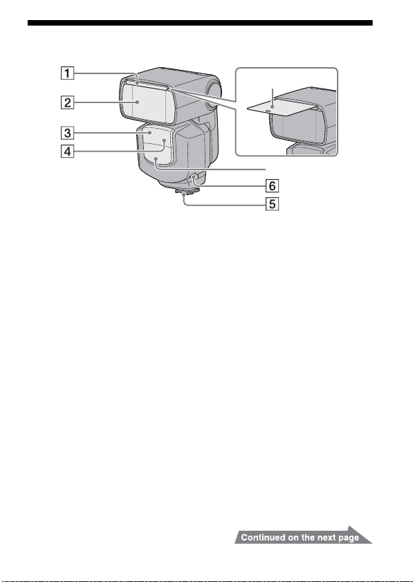
Name of parts
A Built-in wide panel (32)
B Flashtube
C Wireless control signal receiver
(52)
D AF illuminator (65)
Remove the protective sheet from the
front of the AF illuminator before use.
E Multi Interface foot (14)
F LED LIGHT button (27)
G LED light unit (27)
H Bounce sheet (37)
Figures in parentheses are the page
numbers where a description of each
LCD segment can be found.
GB
9
Page 10
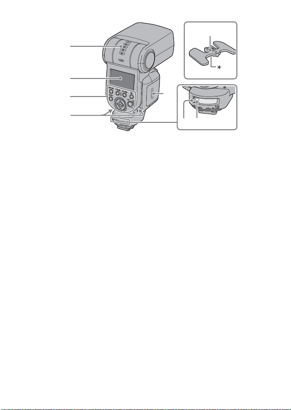
I Bounce indicator (upper/lower
angle) (36)
J LCD panel (12)
K Control panel (11)
L Bounce indicator (side angle)
(36)
GB
10
M Lock lever (14)
N Release button (14)
O Battery chamber door (13)
P Mini-stand (53)
* Tripod attachment hole
Figures in parentheses are the page
numbers where a description of each
LCD segment can be found.
Page 11
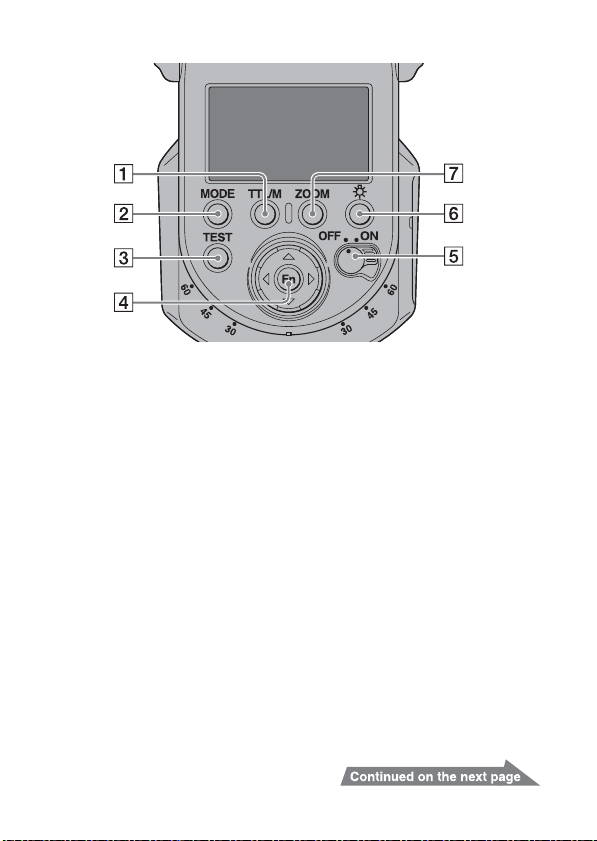
Control panel
Figures in parentheses are the page
numbers where a description of
each LCD segment can be found.
A TTL/M (MANUAL/MULTI)
button (42, 46, 57, 61, 66)
B MODE button (19)
C TEST button (29)
The status while the lamp is lit
Amber: Flash ready
Green: Proper exposure
D Fn (function)/direction buttons
(41, 46, 57, 58, 61, 67)
E Power switch (16)
F LCD illuminator button
G ZOOM button (31)
LCD panel illuminator
If the LCD panel is too dark, you can illuminate it by pressing the LCD illuminator
button.
• The LCD panel remains illuminated for about 8 seconds when the flash unit is
used by itself or connected to a camera that is in power save mode. This time is
extended if the flash or camera is used.
• Press the LCD illuminator button again while the LCD panel is illuminated to
extinguish the LCD panel illuminator.
11
GB
Page 12
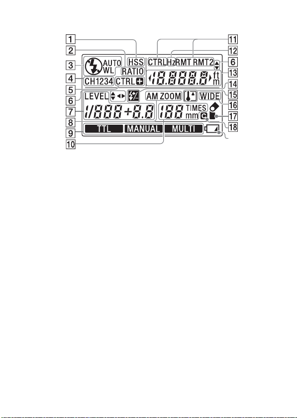
LCD panel
A HSS (High-speed-sync)
indicator (45)
B Ratio-flash indicator (61)
C Flash mode indicator (19)
D Wireless channel indicator (64,
69)
E Wireless controller indicator
(51)
F Operating indicator (67)
G Power-level indicator (41, 46)
H Zoom indicator (30)
I TTL/Manual-flash/Multiple-flash
indicator (41, 46)
J Zoom/Multiple-flash repetition
display (30, 46)
GB
12
K Wireless controller/remote
indicator (55, 58, 61)
L Hz indicator (46)
M Flash-range/Flash-range-
warning (near side, far side)/
Multiple-flash frequency/flashratio display (23, 46, 61)
N Flash compensation indicator
(TTL) (33)
O Overheat indicator (18)
P Wide-panel indicator (32)
Q Bounce indicator (35)
R Custom indicator (67)
S Low-battery indicator (17)
Figures in parentheses are the page
numbers where a description of each
LCD segment can be found.
Page 13
P
reparations
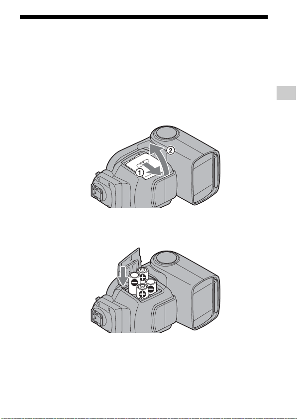
Inserting batteries
The HVL-F43M may be powered by :
• Four LR6 (AA-size) alkaline batteries*
• Four AA-size rechargeable nickel-metal hydride (Ni-MH) batteries*
* Batteries are not supplied.
Always ensure that rechargeable nickel-metal hydride batteries are charged in
the specified charger unit.
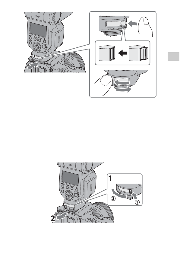
1 Open the battery chamber door as shown.
2 Insert the batteries in the battery chamber as in the
diagram.
Preparations
3 Close the battery chamber door.
• Follow the reverse procedure when opening the battery chamber door.
13
GB
Page 14

Attachment and removal of the
flash unit
Attaching the flash unit to the camera
• Before attaching to the camera, remove the protective cap from the terminal of the
Multi Interface foot of the flash unit and remove the shoe cap from the camera.
• When not using the flash unit, reattach the protective cap to the terminal of its
Multi Interface foot.
• If the built-in flash in the camera is protruding, lower it before attaching the
flash unit.
1 Turn off the power of the flash unit, and rotate the lock
lever towards [RELEASE] while pressing the release
button.
2 Firmly insert the Multi Interface foot all the way into the
Multi Interface Shoe of the camera in the direction of
the arrow.
3 Firmly rotate the lock lever towards [LOCK] to secure
the flash unit.
• This flash unit is suitable for a Multi Interface Shoe. When attaching this unit to
a camera that has an Auto-lock Accessory Shoe, use the Shoe Adaptor (ADPAMA) (not supplied).
GB
14
Page 15
Removing the flash unit from the
1
2
3
camera
1 While pressing the release button 1, rotate the lock
lever towards [RELEASE] 2.
2 With the lock lever in the [RELEASE] position, slide the
flash unit forward.
Preparations
GB
15
Page 16
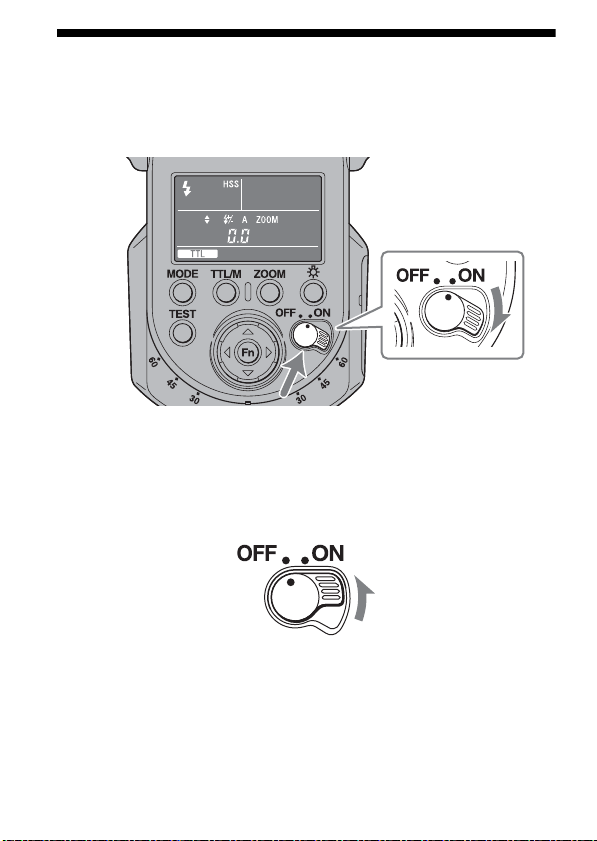
Turning on the power
Set the POWER switch to ON.
The power of the flash unit turns on.
• When the power of the flash unit is turned on, the LCD panel lights up.
• If nothing appears on the LCD panel when the POWER switch is set to ON,
check the orientation of the batteries.
To turn the power off
Set the POWER switch to OFF.
GB
16
Page 17
Power save mode
If the flash unit is not operated for 3 minutes when used by itself or connected to a
camera that is in power save mode, it switches to power save mode to save the
batteries and the LCD display goes out.
• During wireless flash photography (pages 55, 61), the flash unit changes to
power save mode after 60 minutes.
• You can change the time until power save, or disable power save. (page 71)
• The flash unit automatically changes to power save mode when the power
switch of the camera* is set to OFF.
*
Except the DSLR-A100
• When the camera is in power save mode, for example when the LCD monitor
automatically turns off, the camera does not communicate with the flash unit. In
this state, flash mode and TTL/M mode switching, automatic zoom, wide panel
display and flash range display are not linked with your camera.
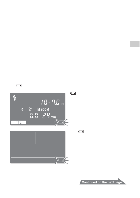
Checking Batteries
The indicator on the data panel blinks when the batteries are low.
blinking
Changing the batteries is recommended.
The flash unit can still be used when the
TEST button lights up in amber.
Only blinking
Flash cannot be used.
Insert new batteries.
Preparations
17
GB
Page 18
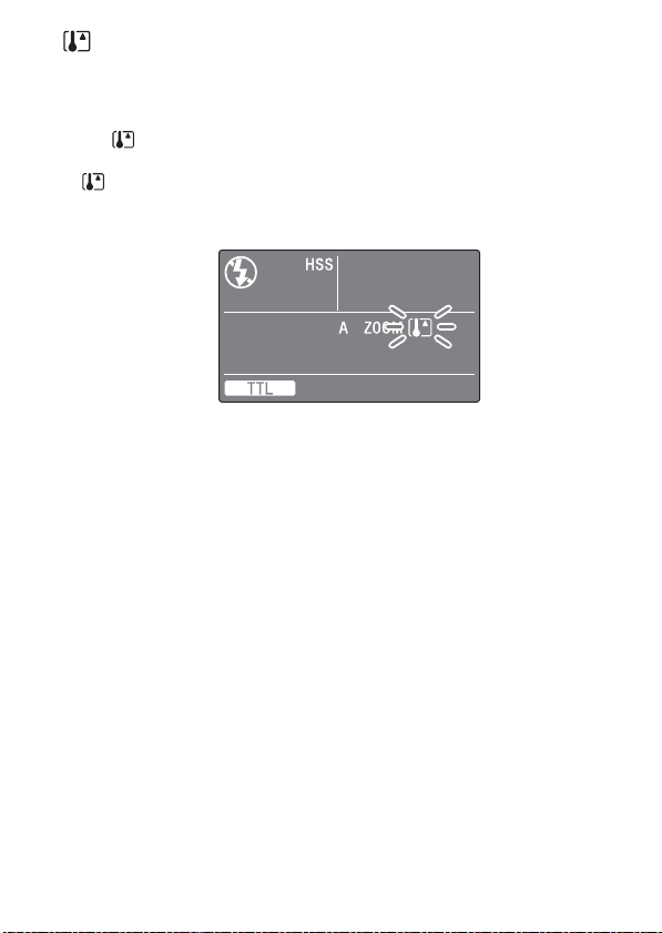
indicator
When the temperature of this unit rises after continuous flash use or use in a high
temperature environment, its internal safety circuit automatically suspends
operation (overheating).
• The indicator blinks when overheating is detected.
• Flash operation is suspended until the temperature of the unit falls and the
indicator turns off.
• When overheating is detected, set the POWER switch to OFF and stop using the
flash unit for about 10 minutes to allow it to cool down.
GB
18
Page 19
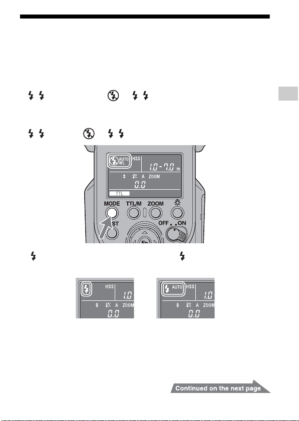
Changing the flash mode
Press the MODE button.
• The indicator on the LCD panel changes as follows.
When the flash unit is not connected to your camera, or when the camera is in
power save mode or the LCD monitor of the camera is being turned off when the
flash unit is connected to the camera:
( AUTO) t WL t t ( AUTO) t . . .
When your camera is turned on and the flash unit is connected to your camera
(WL is not set up):
( AUTO) t t ( AUTO) t . . .
• [ ] lights up when the camera is set to Fill-flash. [ AUTO] lights up when the
camera is set to Auto flash.
Preparations
19
GB
Page 20

About flash mode
• (Fill-flash mode)
The flash unit always fires.
• AUTO (Auto flash mode)
The flash unit is set to this mode when the camera is set to auto flash.
• WL (Wireless flash mode)
This mode is used during wireless flash photography.
• (Un-fill-flash mode)
The flash unit does not fire.
GB
20
Page 21
Basi
cs
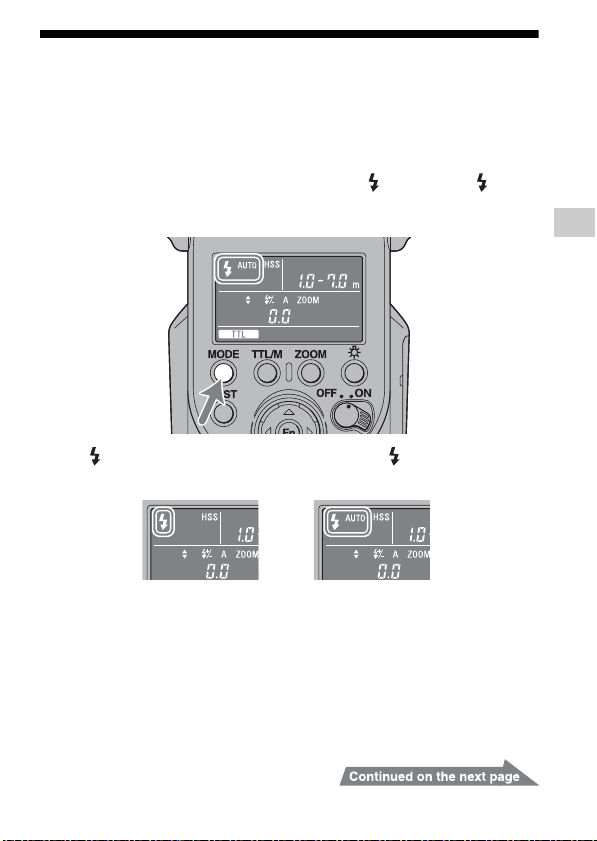
Program auto flash (The basics)
• If your camera has an AUTO mode or Scene Selection mode, they are dealt with
here as program auto.
1 Select the P mode on the camera.
2 Press the MODE button to display [ AUTO] or [ ] on
the LCD panel.
• [ ] lights up when the camera is set to Fill-flash. [ AUTO] lights up
when the camera is set to Auto flash.
Basics
21
GB
Page 22
3 Press the shutter button halfway down and make sure
that the subject is within the flash range.
• See page 23 for details on the flash range.
4 When the flash unit is charged, press the shutter
button to take a photo.
• The flash unit is fully charged when the TEST button on the control panel is
lit in amber.
When the correct exposure has been obtained for the photo just taken, the
TEST button on the control panel blinks in green.
• The photo will be under-exposed because of a lack of luminescence if taken
before charging is complete.
• Press the shutter button after making sure that charging is complete when using
the flash unit with the self-timer.
• The flash mode selected (auto flash ( AUTO), fill-flash ( ), or un-fill-flash
( )) depends on your camera. For details, refer to the operating instructions of
your camera.
GB
22
Page 23

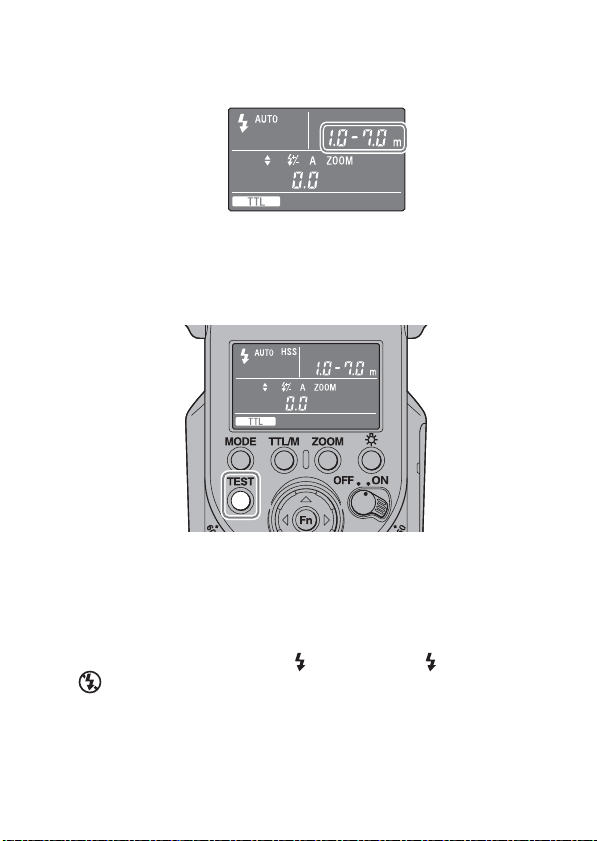
Flash range
Press the shutter button halfway down.
The flash range for the proper exposure is displayed on the LCD panel. Make sure
that the subject is within this range and then take the photo.
The range that can be displayed on the LCD panel is from 1.0 m to 28 m (0.7 m to
28 m for downward bounce; see page 40). When the distance is beyond this range,
or is lit on either side of the Flash range.
Proper exposure is obtained at less than 1.0 m.
If the flash range is less than 1.0 m, the lower area of
the image on the LCD monitor of the camera may
become dark. Change the flash range to adjust the
aperture and ISO sensitivity.
Proper exposure is obtained from 1.0 m to 28 m or
more.
• The flash ranges when using upward bounce flash or wireless flash are not
shown.
• When you take a photo closer than the lower limit of the flash range, the photo
may be over-exposed even if the TEST button blinks green, or the lower area of
the image on the LCD monitor of the camera may darken. Always take a photo
within the indicated flash range.
Basics
23
GB
Page 24

Auto WB Adjustment with Color
Temperature Info
White balance is automatically adjusted by your camera (except the DSLR-A100)
based on color temperature information when the flash unit fires.
• Auto WB Adjustment functions when you attach the flash unit to your camera
and use TTL flash mode on the flash unit.
• This function does not work during manual flash photography. (page 41)
GB
24
Page 25
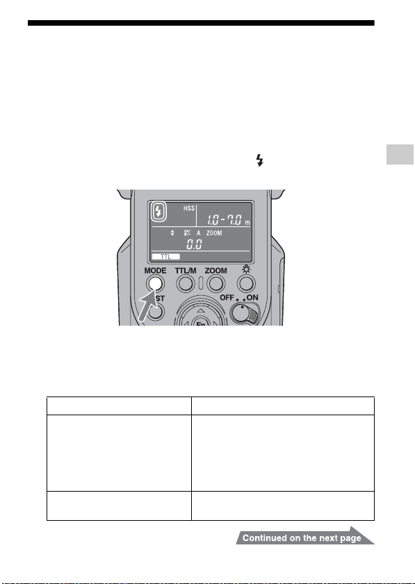
Using flash in each recording
mode of the camera
If the camera is set to aperture priority (A mode), shutter speed priority (S mode) or
manual exposure mode (M mode), TTL flash photography can be performed
according to the mode.
1 Select A, S or M mode on the camera.
2 Press the MODE button to display [ ].
• Fill-flash is selected.
3 Set the aperture and/or shutter speed according to the
mode you select, and then focus the subject. See the
table below.
Recording mode of the camera Settings
A (Aperture priority flash
photography)
S (Shutter speed priority flash
photography)
Set the aperture.
• Reduce the aperture (i.e. increase the fstop) to reduce the flash range, or open
the aperture (i.e. reduce the f-stop) to
increase the flash range.
• The shutter speed is set automatically.
Set the shutter speed.
25
Basics
GB
Page 26
Recording mode of the camera Settings
TTL flash
Manual flash provides a fixed flash intensity irrespective of the brightness of
the subject and the camera setting. TTL* flash measures the light from the
subject that is reflected through the lens.
TTL metering also has a P-TTL metering function, which adds a pre-flash to
TTL metering, and an ADI metering function, which adds distance data to the
P-TTL metering.
This flash unit defines all P-TTL and ADI metering as TTL flash and
is displayed on the LCD panel.
*
TTL = through the lens
• ADI metering is possible in combination with a lens with a built-in distance
encoder. Before using the ADI metering function, check whether your lens
has a built-in distance encoder by referring to the specifications in the
operating instructions supplied with your lens.
M (Manual exposure mode flash
photography)
Set the aperture and shutter speed.
• Reduce the aperture (i.e. increase the fstop) to reduce the flash range, or open
the aperture (i.e. reduce the f-stop) to
increase the flash range.
4 Press the shutter button when charging is complete.
GB
26
Page 27
Shooting with illumination (LED
light)
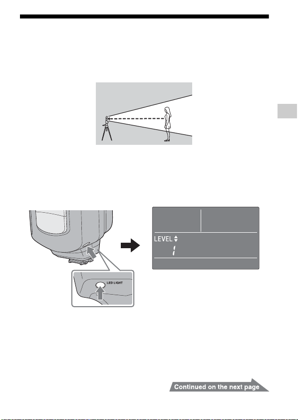
Using the LED light as an illuminator lets you create natural light and shadows and
shoot realistic movies even in poor light such as indoors.
Using the LED light
1 Press the LED LIGHT button.
• The LED light comes on.
• The LEVEL screen appears on the LCD panel.
Basics
27
GB
Page 28

2 Change the brightness with the f or F button.
• You can adjust the brightness of the LED light to 10 levels (1-10).
• When the LED light is on, the [ ] (Flash on) indicator on the camera turns off.
(The flash cannot fire when the LED light is on.)
Turning off the LED light
Press the LED LIGHT button again.
• The LED light goes off and the LCD panel returns to the normal indicator screen.
• The white balance may vary depending on the camera, lens and settings during
shooting. If this happens, set the white balance on the camera.
• The color temperature varies slightly with brightness adjustments and LED
temperature, so check the white balance before recording.
GB
28
Page 29
Ad
vanced Operations
Test-flash
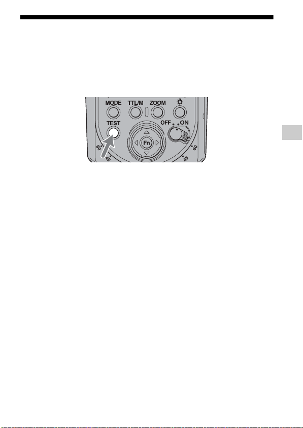
You can try a test flash before shooting. Check the light level using the test flash
when you use a flash meter, etc., in the manual flash (M) mode.
Press the TEST button when the TEST button lights up in
amber.
• The TEST button is turned on as follows, according to the current state of the
flash unit.
– Amber: Flash ready
– Green: Proper exposure
• The light level of the test-flash depends on the light level setting (page 41). The
flash unit fires with a light level of 1/1 in TTL mode.
• You can check shadows on the subject before taking photos with the test-flash
(modeling flash) function. The flash unit has two modeling flash modes, three
times flashes mode and modeling flash mode in which the flash unit fires
repeatedly for four seconds. For details on setting the test-flash mode, see “C05
To change the test-flash mode” (page 71) in “Custom settings”.
Advanced Operations
29
GB
Page 30
Zoom flash coverage
Auto zoom
This flash unit automatically switches optimum flash coverage (zoom flash
coverage) to cover a range of focal lengths from 24 mm to 105 mm when
photographing (auto zoom). Normally, you do not need to switch the flash
coverage manually.
The auto zoom is working when [A ZOOM] is displayed on the LCD panel. The
zoom is not displayed on the LCD panel when [A ZOOM] is displayed.
24 mm focal length 105 mm focal length
• When a lens having a focal length of less than 24 mm is used with auto zoom,
[WIDE] on the LCD panel blinks. Use of the built-in wide panel (page 32) is
recommended in this case to prevent darkening at the periphery of the image.
Auto zoom control optimized for
image sensor size
This unit provides optimal flash coverage according to the image sensor size
(APS-C format/35mm format) of the camera (except the DSLR-A100).
GB
30
Page 31

Manual zoom
Flash coverage & focal length
The larger the focal length figure of the lens on a camera, the further away a
subject can be photographed to take up the full screen; but the area that can be
covered becomes smaller. Conversely, with a smaller focal length figure,
subjects can be photographed with wider coverage. The flash coverage is the
area that the light from the flash at a set intensity or greater can cover evenly,
expressed as an angle. The flash coverage at which you can photograph is
determined by the focal length.
By having flash coverage determined in accordance with focal length, flash
coverage can be expressed as the figure for focal length.
You can manually set the flash coverage regardless of the focal length of the lens in
use (manual zoom).
Press the ZOOM button to select the flash coverage to be
set.
• The zoom coverage is changed in the following order.
105 mm t 70 mm t 50 mm t 35 mm t 28 mm t 24 mm t A ZOOM
t 105 mm t . . .
• When zoom is set manually, [M ZOOM] is displayed above zoom coverage.
• If the flash coverage is set to less than the focal length of the lens in use, the
periphery of the screen darkens.
• The flash coverage of the manual zoom on the LCD panel is the angle of view of
the 35mm-format focal length.
Advanced Operations
31
GB
Page 32

Built-in wide panel (15 mm zoom
angle)
Pulling out the built-in wide panel extends flash coverage to include focal lengths
from 15 mm to less than 24 mm.
Pull out the wide panel and set it at the front of flash tube,
and then push back the bounce sheet.
• [WIDE] is displayed on the LCD panel.
• When putting the wide panel back, push it back in completely and confirm that
[WIDE] on the LCD display turns off.
• Do not pull out the wide panel forcibly. This may damage the wide panel.
• When photographing a flat subject from in front at a focal length of less than 18
mm, the periphery of the screen may darken slightly because of the difference in
intensity of the light that reaches the center and periphery of the screen.
• When using a wide-angle lens with a focal length below 15 mm, the periphery of
the screen may darken.
• The focal length corresponds to the equivalent 35mm-format focal length.
• This flash unit does not support the angle of view of a 16 mm F2.8 Fisheye lens.
• Push back the wide panel and the bounce sheet into the inside of the flash head
when this flash unit is stored in the supplied case.
GB
32
Page 33

Flash compensation
When the flash unit is in a flash mode that supports TTL metering, the flash
intensity is automatically adjusted. However, you can correct this automatically
adjusted flash intensity.
• Flash modes that support TTL metering
– TTL mode
– WL CTRL mode when [TTL RATIO: ON] or [RATIO: OFF] is set
• Setting values:
-3.0, -2.5, -2.0~ ±0.0~ +2.0, +2.5, +3.0 (steps of 0.5)
-3.0, -2.7, -2.3, -2.0~±0.0~+2.0, +2.3, +2.7, +3.0 (steps of 0.3)
• You can change the power level interval (0.5 or 0.3) in the custom settings.
For the setting method, see “Changing the custom settings” (page 69) and “C09
To Change the power level interval” (page 72).
• Does not work with a camera that has an Auto-lock Accessory Shoe.
See online for compatible camera models. (Even with a non-compatible camera,
the flash compensation is shown when communication with the camera is off.
Even in this case, when communication with the camera is restarted the flash
compensation indicator disappears and flash compensation is not carried out.)
Advanced Operations
33
GB
Page 34

• When using the flash unit with an off-camera cable, the power level itself is
corrected but the value of the correction on the flash is not reflected in the Exif
data of the camera.
• If metering is corrected on both the flash unit and the camera, the flash fires
according to the sum of both values. However, the LCD panel of the flash unit
only shows the correction value set on the flash.
GB
34
Page 35

Bounce flash
Bounce flash Normal flash
Using the flash unit with a wall directly behind the subject produces strong
shadows on the wall. By directing the flash unit at the ceiling you can illuminate the
subject with reflected light, reducing the intensity of the shadows and producing a
softer light on the screen.
Advanced Operations
35
GB
Page 36

Rotate the flash unit upwards or to the left and right while
holding the camera firmly.
• When the flash is rotated upwards, the flash range is not displayed on the LCD
panel. High-speed sync (page 45) is also cleared.
• When the flash is rotated upwards, the bounce indicator does not appear.
• Use a white ceiling or wall to reflect the flash. A colored surface may color the
light. High ceilings or glass are not recommended.
GB
36
Page 37

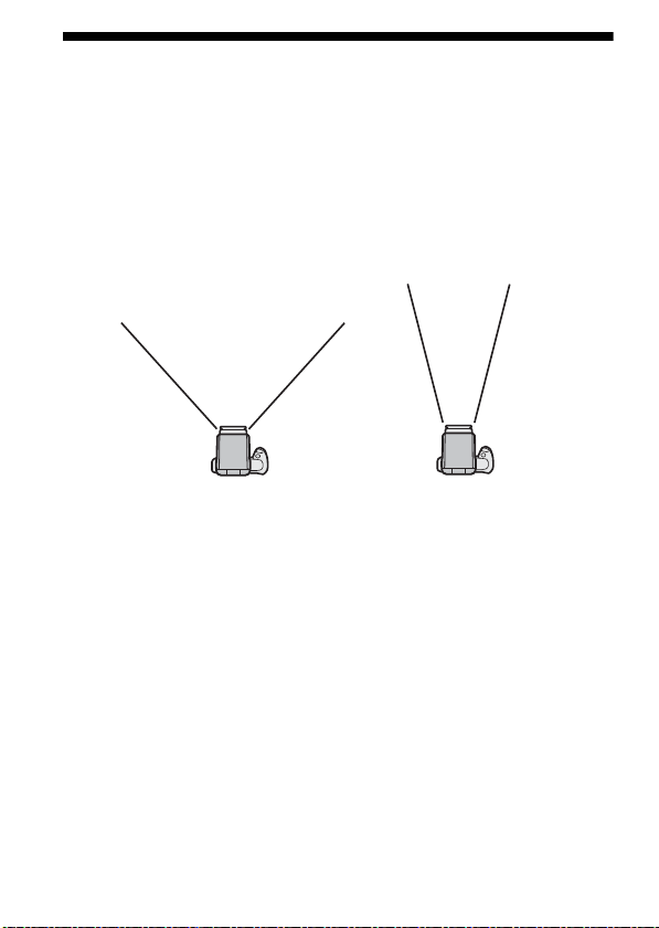
Adjusting bounce angle
Correct
Incorrect
Simultaneously using direct light and bounced light from the flash unit produces
uneven lighting. Adjust to the best bounce angle while performing a test flash in
actual shooting conditions.
Examples of shooting conditions:
• distance from camera to reflective surface
•flash range
• focal length of lens
When the flash is bounced upwards
Determine the angle in relation to the following table.
Focal length of lens Bounce angle
70 mm minimum 30°, 45°
28 mm - 70 mm 60°
28 mm maximum 75°, 90°
Advanced Operations
37
GB
Page 38

Using the bounce sheet
The bounce sheet creates a highlight in the subject's eyes and makes the subject
look more vibrant.
• The bounce sheet is pulled out when the wide panel is pulled out. Push back the
wide panel.
• When using the bounce sheet, set the bounce angle to 90° upwards.
Quick shift bounce
When shooting in the portrait position, you can set the same bounce flash as that
used when shooting in the landscape position, and also use the control panel at
proper direction.
90° sideways bounce
When the bounce angle is set to 90° sideways and 0° upwards while shooting in the
portrait position, the top and bottom of the photo may darken. In this case, use the
built-in wide panel or set the bounce angle to
0° sideways.
GB
38
Page 39

• blinks on the LCD panel.
• When the zoom flash coverage is set to [A ZOOM] while using 90° sideways
bounce, the coverage is adjusted automatically to the wide angle. In this case,
the flash range is shorter than that for 0° sideways bounce.
Advanced Operations
39
GB
Page 40

Close-up photography
(downward bounce)
Tilt the flash slightly downwards when photographing objects between 0.7 m and
1.0 m from the camera to ensure accurate illumination.
Rotate the flash downwards with holding the camera
firmly.
• The rotation angle is 8°.
• appears on the LCD panel.
• When photographing at a distance closer than 0.7 m, the flash will not be able to
completely cover the subject and the bottom of the picture will be darker. Use an
off-camera flash, Macro Twin Flash, or Ring Light.
• The downward bounce can be used only when the bounce angle is set to 0° or
90° sideways.
• The lenses with long length may obstruct the flash light.
GB
40
Page 41

Manual flash (M)
TTL flash metering Manual flash metering
Normal TTL flash metering automatically adjusts the flash intensity to provide the
proper exposure for the subject. Manual flash provides a fixed flash intensity
irrespective of the brightness of the subject and the camera setting.
• As manual flash is not affected by the reflectivity of the subject, it is convenient
for use with subjects with extremely high or low reflectivity.
• Manual flash can only be used when the camera is set to M (Manual) mode. In
other modes, TTL measuring is selected automatically.
• You can change the custom settings of this unit to enable manual flash
photography in modes other than M mode of your camera. (page 67)
Advanced Operations
41
GB
Page 42

1 Press the TTL/M button to display on the LCD
panel.
• The modes change in the following order.
GB
42
Page 43

2 Press the f or F button to select the power level to be
set.
• The power level can be set to the following.
1/1 (maximum) t 1/2 t 1/4 t 1/8 t 1/16 t 1/32 t 1/64 t 1/128
(minimum)
• The power level indication may sometimes differ depending on whether the
power level was increased or decreased, even if the power level is the same.
F
button
1/1 t 1/1(-0.3) t 1/1(-0.7) t 1/2 t 1/2(-0.3) ... 1/64(-0.3)
t 1/64(-0.7) t 1/128
f
button
1/1 T 1/2(+0.7) T 1/2(+0.3) T 1/2 T 1/4(+0.7) ... 1/128(+0.7)
T 1/128(+0.3) T 1/128
• The power can be set to up to 22 levels by changing the power level
interval. See “C09 To Change the power level interval” on page 72 for
details.
Advanced Operations
43
GB
Page 44

• When the shutter button is pressed halfway down, the distance at which the
proper exposure is obtained appears on the LCD panel. Set the aperture to match
the displayed distance to the shooting distance.
Proper exposure is obtained at less than 1.0 m.
If the flash range is less than 1.0 m, the lower area of
the image on the LCD monitor of the camera may
become dark. Change the flash range to adjust the
aperture and ISO sensitivity.
Proper exposure is obtained at more than 28 m.
• In manual flash photography, if the power level is set at 1/1 then the flash will go
off at full power. The power level range (e.g. 1/1 t 1/2) corresponds to the
aperture range (e.g. F4 t 5.6).
• The flash range check indication of the TEST button (blinks in green) does not
work after a photo is taken with the manual flash.
GB
44
Page 45

High-speed sync (HSS)
Flash Sync Speed
Flash photography is generally associated with a maximum shutter speed
referred to as the flash sync speed. This restriction does not apply to cameras
designed for high-speed sync (HSS) photography, since they allow flash
photography at the maximum shutter speed of the camera.
High-speed sync Normal flash
High-speed sync eliminates the restrictions of flash sync speed and enables the
flash to be used through the entire shutter speed range of the camera. The increased
selectable aperture range allows flash photography with a wide aperture, leaving
the background out of focus and accentuating the front subject. Even when
photographing at a wide f-stop in the A mode or M mode of the camera, when the
background is very bright and the shot will normally be over-exposed, you can
adjust the exposure by using the high-speed shutter.
For details on turning the HSS setting off, see “Custom settings” (page 67).
45
Advanced Operations
GB
Page 46

Multiple flash (MULTI)
The flash is triggered a number of times while the shutter is open (multiple flash).
Multiple flash allows motion of the subject to be captured in a photograph for later
analysis.
• The camera must be set to the M mode for multiple flash photography. In modes
other than the M mode of the camera, the proper exposure may not be obtained.
• The custom settings of this unit enable multiple flash photography in modes
other than the M mode of your camera. (page 67)
1 Press the TTL/M button to display on the LCD
panel.
GB
46
Page 47

2 Press the Fn button to make [Hz] blink, and then press
the f or F button to select the flash frequency.
• The figures show the number of flashes per second.
• The flash frequency may be selected from the following.
100, 90, 80, 70, 60, 50, 40, 30, 20, 10, 9, 8, 7, 6, 5, 4, 3, 2, 1
• Keep the f or F button pressed down to repeatedly change the value.
3 Press the Fn button to make [TIMES] blink, and then
press the f or F button to select the number of flashes.
• The number of flashes may be selected from the following.
--, 100, 90, 80, 70, 60, 50, 45, 40, 35, 30, 25, 20, 15, 10, 9, 8, 7, 6, 5, 4, 3, 2
• Keep the f or F button pressed down to repeatedly change the value.
• When “--” is selected, flashes continue at the set frequency while the shutter
is open.
Advanced Operations
47
GB
Page 48

4 Press the Fn button to make the power-level indicator
blink, and then press the f or F button to select the
power level to be set.
• The power level can be set to the following.
1/8 t 1/16 t 1/32 t 1/64 t 1/128
• You can change the power level interval so that the power can be set to up
to 13 levels.
See “C09 To Change the power level interval” on page 72 for details.
GB
48
Page 49

5 Press the Fn button to finish the setting.
6 Set the shutter speed and aperture.
• The shutter speed should at least equal the number of flashes (TIME)
divided by the flash frequency (Hz).
For example, if the number of flashes is 10 and the flash frequency is 5, set
the shutter speed of your camera to 2 seconds or more.
7 When the flash is fully charged, press the shutter
button to take the photo.
• The distance at which the proper exposure is obtained with a single flash is
displayed on the LCD panel.
• To prevent shaking, the use of a tripod is recommended during multiple
flash photography.
• Test flash will fire at the selected frequency/number/level while the TEST
button is being pressed if [TEST1] is selected in the custom setting. When
[TEST3] or [TESTM] is selected, the flash three times or the four second
modeling flash has priority.
Advanced Operations
49
GB
Page 50

Maximum number of continuous flashes
The maximum number of continuous flashes during multiple flash photography is
limited by the charge in the battery. Use the following values as a guide.
With alkaline batteries
Power level
100 90 80 70 6 0 50 40 30 2 0 10 9 8 7 6 5 4 3 2 1
1/8
555555556666778910100*100
1/16
8 8 9 9 9 9 10 10 10 15 15 20 20 30 45 65 100*100*100
1/32
15 15 1 5 15 17 17 1 8 18 20 40 5 0 65 80 100*100*100*100*100*100
1/64
30 30 3 2 32 35 37 4 0 45 75 100*100*100*100*100*100*100*100*100*100
1/128
60 60 65 65 70 100*100*100*100*100*100*100*100*100*100*100*100*100*100
With nickel-metal hydride batteries (When using 2100 mAh)
Power level
100 90 80 70 6 0 50 40 30 2 0 10 9 8 7 6 5 4 3 2 1
1/8
5555555667788101025100*100*100
1/16
8 8 9 9 9 9 10 10 10 15 20 30 60 75 100*100*100*100*100
1/32
17 17 1 8 18 18 19 2 0 20 40 80 100*100*100*100*100*100*100*100*100
1/64
32 33 3 5 36 40 45 5 5 95 100*100*100*100*100*100*100*100*100*100*100
1/128
63 65 70 100*100*100*100*100*100*100*100*100*100*100*100*100*100*100*100
• The maximum number of flashes varies with the type of battery and its
condition.
Flash frequency (Hz)
100* signifies more than 100.
Flash frequency (Hz)
100* signifies more than 100.
*
*
*
*
*
*
*
*
*
*
GB
50
Page 51

Wireless flash mode (WL)
Normal flash Wireless flash [A], [B]
Wireless flash [C]
(Lighting ratio control mode)
This flash unit enables the following wireless flash photography.
[A] Wireless flash photography (HVL-F43M: off-camera flash)
The camera's built-in flash is the controller (the flash that emits control light) and
the HVL-F43M is the off-camera flash (the flash that is away from the camera).
[B] Wireless flash photography (HVL-F43M: controller)
The HVL-F43M is the controller and another flash is the off-camera flash.
[C] Multiple wireless flash photography with lighting ratio control
Using the HVL-F43M as the controller, a camera that supports lighting ratio
control can group a number of off-camera flashes and control the lighting ratio.
Advanced Operations
51
GB
Page 52

Wireless Flash Range
Distance between camera and subject
(see Table 1)
Distance between flash
and subject
(see Table 2)
Do not place the flash directly
behind the subject
Place the camera and flash unit
within a 1 m to 5 m radius of the
subject
The wireless flash uses a light signal from the flash as a trigger to operate the offcamera flash unit. Follow the points below when positioning the camera, flash, and
subject.
• Photograph in dark locations indoors.
• Place the off-camera flash within the gray area in the following diagram.
Distance camera-HVL-F43M-subject
Distance
camera-subject
(Table 1)
Shutter speed
Aperture
2.8
5.6
All shutter spe eds Sync speed or slower 1/250 sec 1 /500 sec 1/ 1000 sec 1/2000 sec
1.4 - 5 1 - 5 1 - 3 1 - 2.1 1 - 1.5 1 - 1.1
4
1 - 5 1 - 5 1 - 2.1 1 - 1.5 1 - 1.1 –
1 - 5 1 - 5 1 - 1.5 1 - 1.1 – –
Other than HSS HSS
• The distances in the above table assume the use of ISO 100. If ISO 400 is used
the distances must be multiplied by a factor of two (assume a limit of 5 m).
• The flash range is not displayed on the LCD panel when using wireless flash.
GB
52
Distance HVL-F43M - subject
(Table 2)
Units: m
Page 53

Opening and closing the included
mini-stand
• The mini-stand is collapsible and must be open when used.
Attaching and removing the ministand
• Use the supplied mini-stand when the flash unit is separate from the camera.
Attachment Removal
• See page 14 on operation for the release button and lock lever.
• You can attach the flash unit to a tripod using the tripod attachment hole under
the mini-stand. Use the tripod equipped with the screw under 5.5 mm. Because
the tripod equipped with the screw over 5.5 mm cannot hold the mini-stand
firmly, mini-stand may be damaged.
53
Advanced Operations
GB
Page 54

• When mini-stand break into each part, fit the part of shaft into the other part.
GB
54
Page 55

[A] Wireless flash photography using
Built-in flash
HVL-F43M
the HVL-F43M as the off-camera flash
Use only an off-camera flash unit, using the light from the built-in flash as a signal.
1 Attach the flash unit to the camera and turn the power
of the flash unit and camera on.
2 Set the camera to wireless flash mode.
• The setting method differs depending on the camera used. For details, refer
to the operating instructions of your camera.
• When the camera is set to wireless the flash is also set to wireless
automatically, and WL is displayed on the LCD panel.
The flash channel information is transmitted to the camera.
• The light level can be changed even for the wireless flash mode. For details,
see page 72.
3 Remove the flash unit from the camera and raise the
built-in flash.
• Make sure that the wireless remote mode display on the LCD panel of the
flash unit is [RMT] or [RMT2].
4 Set up the camera and flash unit.
• Set up the camera and flash unit in a dark location, such as indoors.
• See page 52 for details.
Advanced Operations
55
GB
Page 56

5 Make sure that the built-in flash and flash unit are fully
charged.
• The built-in flash full-charge indication varies depending on the camera.
For details, refer to the operating instructions of the camera.
• When the flash unit is fully charged in the wireless flash mode, the AF
illuminator on the front blinks, and the TEST button is lit in amber.
6 Use test-flash to check the flash.
• During wireless flash photography, the test-flash method differs depending
on the camera used. For details, refer to the operation instructions of your
camera.
• If the test-flash does not work, change the position of the camera, flash, and
subject, or point the wireless control-signal receiver towards the camera.
7 Check again that the built-in flash and the flash unit are
fully charged, and press the shutter button to take the
photo.
GB
56
Page 57

Setting wireless flash by flash only
Once you have performed the wireless flash setup in step [A], if you continue to use
the same camera and flash combination without changing the wireless channel then
you can also set the flash and camera separately to wireless.
Camera setting:
Set the camera to the wireless flash mode.
For details, refer to the operating instructions supplied with your camera.
Flash setting:
1 Press the TTL/M button to display or .
• When selecting , the flash unit fires with the power level to be
set.
2 Press the MODE button repeatedly to display [WL], and
then press the Fn button.
3 Press the g or G button to make [RMT] or [RMT2] blink,
and then press the Fn button.
• Make sure that the wireless channel of the off-camera flash is set to the
same channel as the controller.
For details on setting the wireless channel, see “Custom settings” (page
67).
Advanced Operations
57
GB
Page 58

[B] Wireless flash photography using
HVL-F43M
Off-camera flash
the HVL-F43M as the controller
When using the DSLR-A900, DSLR-A850, DSLR-A700, SLT-A99V, SLT-A77V,
SLT-A65V, SLT-A57, SLT-A37, NEX-7, NEX-6, DSC-RX1 or DSC-RX1R, you
can perform wireless flash photography by using more than 2 flash units, one as a
controller and the other as an off-camera flash unit. Use the HVL-F43M as the
controller.
If you use an HVL-F56AM or HVL-F36AM as an off-camera flash when using the
DSLR-A900, DSLR-A850, SLT-A99V, SLT-A77V, SLT-A65V, SLT-A57, SLTA37, NEX-7, NEX-6, DSC-RX1 or DSC-RX1R, set the wireless controller mode
of the HVL-F43M to [CTRL2] ([CTRL] on the LCD display). For details on
setting, see “Custom settings” (C03) on page 70.
1 Set the camera, flash (controller), flash (off-camera
flash) to wireless flash.
Camera Setting:
Set the camera to wireless flash.
For details, refer to the operating instructions supplied with your camera.
Controller Setting:
1 Press the MODE button repeatedly to display [WL],
and then press the Fn button.
2 Press the g or G button to make [CTRL] blink, and
then press the Fn button.
• [CTRL+] or [CTRL] is displayed.
GB
58
Page 59

Off-camera flash setting:
Set the wireless flash while the flash unit is attached to the camera, and then
remove it from the camera. For details, refer to the operating instructions
supplied with the external flash. When the HVL-F43M is used as the offcamera flash, see page 57, and set the remote mode to [RMT].
2 Attach the controller to the camera, and turn on the
power of the camera, controller, off-camera flash.
3 Set up the camera with the controller and the off-
camera flash.
• See page 52 for details.
4 Make sure that the controller and the flash unit are fully
charged.
• When the flash unit is fully charged in the wireless flash mode, the AF
illuminator on the front blinks, and the TEST button is lit in amber.
5 Use test-flash to check the flash.
• The test-flash method differs depending on the camera used. For details,
refer to the operating instructions of your camera.
• If the test-flash does not work, change the position of the camera, flash, and
subject, or point the wireless control-signal receiver towards the camera.
Moreover, make sure that wireless channel of the off-camera flash is set to
the same channel as the controller.
Advanced Operations
59
GB
Page 60

6 Check again that the controller and the flash unit are
fully charged, and press the shutter button to take the
photo.
• Even if RATIO is set to [OFF], the controller flashes to transmit a signal.
GB
60
Page 61

[C] Multiple wireless flash
HVL-F43M
(Controller)
Off-camera flash
(RMT2)
Off-camera flash
(RMT)
photography with lighting ratio
control
When using the DSLR-A900, DSLR-A850, DSLR-A700, SLT-A99V, SLT-A77V,
SLT-A65V, SLT-A57, SLT-A37, NEX-7, NEX-6, DSC-RX1 or DSC-RX1R, you
can perform wireless flash photography while controlling the lighting ratio between
a maximum of 3 groups including the controller and two groups of off-camera flash
units.
Controller: HVL-F43M (this unit)
Off-camera flashes: HVL-F58AM, HVL-F60M, HVL-F43AM, HVL-F43M,
These flash units can be set in 2 groups (RMT and RMT2).
• Any combination of HVL-F58AM, HVL-F60M, HVL-F43AM, HVL-F43M and
HVL-F42AM can be used in the [RMT] group. HVL-F58AM, HVL-F60M, HVLF43AM or HVL-F43M set to [CTRL1] (CTRL+ on the LCD display) can be used in
the [RMT2] group.
• HVL-F42AM being used as an off-camera flash is recognized as the [RMT] group.
When using the HVL-F42AM as an off-camera flash in 3-group wireless flash
photography, use an HVL-F58AM, HVL-F60M, HVL-F43AM or HVL-F43M as the
other off-camera flash which can be set to [RMT2].
• When using the DSLR-A900, DSLR-A850, SLT-A99V, SLT-A77V, SLT-A65V,
SLT-A57, SLT-A37, NEX-7, NEX-6, DSC-RX1 or DSC-RX1R, you can use an HVLF56AM and/or HVL-F36AM as off-camera flashes. Set the wireless controller mode
of the HVL-F43M to [CTRL2] ([CTRL] on the LCD display). In this mode, the HVLF56AM and/or HVL-F36AM are in the [RMT] group, and you can control the lighting
ratio of up to 2 groups using a HVL-F58AM, HVL-F60M, HVL-F43AM or HVLF43M as a controller. For details on setting the controller mode, see [C03] in “Custom
settings” (page 70).
HVL-F42AM
Advanced Operations
61
GB
Page 62

• The whole power level ratio is displayed using the flash-range/multiple-flash
frequency/flash-ratio display on the LCD panel for the wireless flash photography with
the lighting ratio control.
e.g.)
When a display is [4:2:1], the flash of each group fires with power level of 4/7, 2/7 and
1/7 of the whole.
1 Set the camera, flash (controller), and flash (off-camera
flash) to wireless flash.
Camera Setting:
Set the camera to wireless flash.
For details, refer to the operating instructions supplied with your camera.
Controller Setting:
1 Press the MODE button repeatedly to display [WL],
and then press the Fn button.
2 Press the g or G button to make [CTRL] and
[RATIO] blink, and then press the Fn button.
3 Press the f or F button to select the lighting ratio.
• The lighting ratio may be set to the following.
1, 2, 4, 8, 16, --
* The flash unit cannot flash when the lighting ratio is set to [--].
4 Press the g or G button to select the lighting ratio
of the controller and off-camera flash units (RMT,
RMT2), and then press the Fn button.
• Set the power level ratio to [--] on the flash unit when there is an offcamera flash (RMT/RMT2) you don't want to fire when you use the
flash unit with the controller after setting the flash unit to [CTRL1].
*
GB
62
Page 63

5 Press the TTL/M button to display .
• When is selected, manual setting flash is used with the
lighting ratio control.
Off-camera flash setting:
Set the wireless flash while the flash unit is attached to the camera, and then
remove it from the camera. For details, refer to the operating instructions
supplied with the external flash. When the HVL-F43M is used as the offcamera flash, see page 57.
2 Attach the controller to the camera, and turn on the
power of the camera, controller, and off-camera flash.
3 Set up the camera with the controller and the off-
camera flash.
• See page 52 for details.
4 Make sure that the controller and the flash unit are fully
charged.
• When the flash unit is fully charged in the wireless flash mode, the AF
illuminator on the front blinks, and the TEST button is lit in amber.
5 Use test-flash to check the flash.
• The test-flash method differs depending on the camera used. For details,
refer the operating instructions of your camera.
• If the test-flash does not work, change the position of the camera, flash and
subject, or point the wireless control-signal receiver towards the camera.
Moreover, make sure that the wireless channel of the off-camera flash is set
to the same channel as the controller.
6 Check again that the controller and the flash unit are
fully charged, and press the shutter button to take the
photo.
63
Advanced Operations
GB
Page 64

Notes on wireless flash
• You cannot use a flash meter or color meter in wireless flash mode because the
pre-flash goes off.
• Test flash for the wireless flash is in the currently selected test flash mode. One
flash occurs with [TEST1] and three flashes with [TEST3]. Flashes continue for
four seconds with [TESTM]. For details of test flash, See “Custom settings”
(page 67).
• The zoom position for the HVL-F43M is automatically set to 24 mm. A zoom
position other than 24 mm is not recommended.
• In wireless flash mode, ADI metering is canceled and P-TTL flash metering is
used automatically (page 26).
• Multiple flash cannot be used.
• If another wireless flash is being used nearby, you can change the channel in the
custom settings to prevent interference (page 67).
• When photographing with the wireless flash, the flash unit may in rare cases go
off by mistake due to ambient static electricity or electromagnetic noise.
When the flash is not in use, select [ ] using the MODE button.
• The flash unit may in rare cases provide incorrect luminescence because the
signal light does not reach the subject, etc,. due to the position in which the
wireless flash was installed. In this case you can prevent incorrect luminescence
by changing the installation position of the wireless flash or changing the
wireless channel setting in the custom settings (page 67).
• You can use several off-camera flashes at the same time.
• The off-camera flash fires with the power level set in each flash when the offcamera flash is in the MANUAL mode.
GB
64
Page 65

AF illuminator
In low-light or when subject contrast is low, when the shutter button is pressed
halfway down for Auto Focus, the red lamp on the front of the flash unit will light.
This is the AF illuminator used as an aid in Auto Focus.
• The AF illuminator operates even when [ ] is displayed on the LCD panel.
• The camera AF illuminator does not operate while the flash AF illuminator is
operating.
• The AF illuminator does not operate while Continuous AF is used in focusing
mode (when continually focusing on a moving subject).
• The AF illuminator may not operate if the focal length of the lens is greater than
300 mm. The flash unit will not operate when removed from the camera.
Advanced Operations
65
GB
Page 66

Reset to the default settings
Press the MODE and TTL/M buttons together for more than
three seconds.
Most flash functions return to their default settings.
Item Default settings Page
Flash on/off On ( or Auto) 19
Flash compensation 0.0 33
Flash coverage (zoom) Auto zoom (105 mm) 30
Flash mode (TTL/M/MULTI) TTL 41, 46
Wireless flash (WL) RMT 51
Lighting ratio 1:1:1 61
Power level in TTL/M (LEVEL) 1/1 41, 46
Power level in multiple flash (LEVEL) 1/32 46
Frequency in multiple flash (Hz) 5 46
Repetition in multiple flash (TIMES) 10 46
LED light power level (LEVEL) 1 (Minimum) 27
Custom settings (page 67) is not reset.
GB
66
Page 67

Custom settings
The various flash settings may be changed as necessary.
The following 9 items may be changed. (
• C01 HSS setting (on
• C02 Wireless channel setting (channels 1
• C03 Wireless controller mode setting (1
• C04 Recording mode in which manual flash or multiple-flash may be set
(M mode only
• C05 Test-flash setting (once
• C06 Time to power save (30 seconds/3 minutes
• C07 Time to power save when using wireless flash (60 minutes
• C08 Flash range units (meters
• C09 Switch power level interval (0.3
/off)
/all modes)
Performing the custom settings
The custom settings are changed as follows.
1 Press the Fn button for more than three seconds while
the power switch is set to ON.
• The first item (C01 HSS setting) is displayed.
*
Default settings are underlined.)
to 4)
/2)
/3 times/4 seconds)
/feet)
/0.5)
/30 minutes/none)
/none)
Advanced Operations
67
GB
Page 68

2 Select the setting item to be changed by pressing g or
G.
3 Change the setting by pressing f or F, and then press
the Fn button.
• Custom setting is finished and the LCD display returns to recording mode.
• When a setting other than the default setting is selected in C03, C04, C06 or
C07, remains on the LCD panel.
• The selected settings are maintained even if the flash unit is switched off or
the battery is removed.
GB
68
Page 69

Changing the custom settings
on off
channel-1 channel-2 channel-3 channel-4
C01 To set the high-speed sync
• This flash unit is set to high-speed sync automatically when the shutter speed is
set faster than flash sync speed. Flash sync speed may differ depending on the
camera. For further details of flash sync speed, refer to operating instructions
supplied with your camera.
• Taking photos in bright locations is recommended.
• High-speed sync cannot be used with bounce flash.
• Using a flash meter or color meter with high-speed sync is not recommended
because it interferes with achieving the proper exposure and color.
• The flash range becomes shorter than that of normal flash photography when the
high speed sync is used. Make sure that the subject is in the flash range.
• You can also use the high speed sync with when using wireless flash
photography.
• If you select [OFF], high-speed sync is cancelled. When high-speed sync is
cancelled, the shutter speed cannot be set faster than the sync speed.
C02 To change the channel setting of the wireless flash
• Attach the flash unit to the camera and press the shutter button halfway down
after changing the channel.
Advanced Operations
69
GB
Page 70

C03 To select wireless control mode
control 1 control 2
M mode only All modes
When using the HVL-F43M as the controller in wireless flash photography, select
[CTRL1] or [CTRL2] depending on the models of the off-camera flashes.
Depending on the models of the off-camera flashes, the following appears on the
LCD display.
• [CTRL1] mode: [CTRL+]
When using only the HVL-F58AM, HVL-F60M, HVL-F43AM, HVL-F43M
or HVL-F42AM as an off-camera flash, select this mode.
• [CTRL2] mode: [CTRL]
When also using the HVL-F56AM or HVL-F36AM as an off-camera flash,
select this mode.
C04 To change the recording mode that can use the
manual flash mode (M) and multiple flash mode
• When [PASM] is selected, manual flash photography and multiple flash
photography may be used in all recording modes of your camera. The proper
exposure may not be obtained with photography in modes other than the M
mode of your camera, therefore we recommend the M mode of your camera.
• When [PASM] is selected, this unit remains in manual flash mode even if the
recording mode of the camera is changed to A (automatic mode).
GB
70
Page 71

C05 To change the test-flash mode
once 3 times 4 seconds
30 seconds 3 minutes 30 minutes none
60 minutes none
[TEST1] : flashes once depending on the power level that is set.
[TEST3] : flashes three times at a specific rate.
[TESTM] : flashes for four seconds at a specific rate.
C06 To change the time until power save mode
[PS 0.5] : changes to power save mode after 30 seconds.
[PS 3] : changes to power save mode after 3 minutes.
[PS 30] : changes to power save mode after 30 minutes.
[PS --] : disables power save mode.
C07 To change the time until power save mode when
using a wireless flash
Advanced Operations
[PS 60] : changes to power save mode after 60 minutes.
[PS --] : disables power save mode.
71
GB
Page 72

C08 To change the flash range unit
meters feet
0.3 0.5
C09 To Change the power level interval
[0.3]: changes the power level by 0.3 EV
[0.5]: changes the power level by 0.5 EV
GB
72
Page 73

Power level indication
According to the power level interval you set, the power level changes as follows.
When set to [0.3]
F
button
1/1 t 1/1(-0.3) t 1/1(-0.7) t 1/2 t 1/2(-0.3) ... 1/64(-0.3) t 1/64(-0.7)
t 1/128
f button
1/1 T 1/2(+0.7) T 1/2(+0.3) T 1/2 T 1/4(+0.7) ... 1/128(+0.7) T 1/128(+0.3)
T 1/128
When set to [0.5]
F button
1/1 t 1/1(-0.5) t 1/2 t 1/2(-0.5) ... 1/64 t 1/64(-0.5) t 1/128
f button
1/1 T 1/2(+0.5) T 1/2 T 1/4(+0.5) ... 1/64 T 1/128(+0.5) T 1/128
Sometimes the power level indication differs depending on whether the f button or
F button is used, even if the power level is the same.
Example:
1/1(-0.7) is the same as 1/2(+0.3).
1/1(-0.5) is the same as 1/2(+0.5).
Advanced Operations
73
GB
Page 74

Additi
onal Information
Notes on use
While shooting
• This flash unit generates strong light, so it should not be used directly in front of
the eyes.
• Do not use the flash 20 times in a row or in quick succession in order to prevent
heating and degradation of the camera and flash unit. (when the power level is
1/32, 40 times in a row.)
Stop using the flash unit and cool it for 10 minutes or more, if the flash is
triggered up to the limit for the number of times in quick succession.
• Do not use the flash near people when rotating the flashtube during bounce
photography. The flash light may damage the eyes, or the hot flashtube may
cause a burn.
• When rotating the flashtube, be careful not to catch your fingers in the rotating
part. You may be injured.
• This flash unit is not waterproof. Be careful not to bring it into contact with
water or sand when using it at the seashore, for example. Contact with water,
sand, dust, or salt may result in a malfunction.
• When closing the battery chamber door, press it firmly in while sliding it fully
across. Be careful not to injure yourself by catching your finger in the battery
chamber door when closing it.
Batteries
• The battery level displayed on the LCD panel may be lower than the actual
battery capacity, due to temperature and storage conditions. The displayed
battery level is restored to the correct value after the flash has been used a few
times.
• Nickel-metal hydride batteries can lose power suddenly. If the low-battery
indicator starts blinking or the flash can no longer be used while taking pictures,
change or recharge the batteries.
• The flash frequency and number of flashes provided by new batteries may vary
from the values shown in the table, depending on the time elapsed since
manufacture of the batteries.
GB
74
Page 75

• Remove the batteries only after turning the power off and waiting several
minutes, when changing the batteries. The batteries may be hot, depending on
the battery type. Remove them carefully.
• Remove and store the batteries when you do not intend to use the camera for a
long time.
Temperature
• The flash unit may be used over a temperature range of 0 °C to 40 °C.
• Do not expose the flash unit to extremely high temperatures (e.g. in direct
sunlight inside a vehicle) or high humidity.
• To prevent condensation forming on the flash, place it in a sealed plastic bag
when bringing it from a cold environment into a warm environment. Allow it to
reach room temperature before removing it from the bag.
• Battery capacity decreases at colder temperatures. Keep your camera and spare
batteries in a warm inside pocket when shooting in cold weather. The
low-battery indicator may blink even when there is some power left in the
batteries in cold weather. Batteries will regain some of their capacity when
warmed to normal operating temperature.
Additional Information
75
GB
Page 76

Maintenance
Remove this unit from the camera. Clean the flash with a dry soft cloth. If the flash
has been in contact with sand, wiping will damage the surface, and it should
therefore be cleaned gently using a blower. In the event of stubborn stains, use a
cloth lightly dampened with a mild detergent solution, and then wipe the unit clean
with a dry soft cloth. Never use strong solvents, such as thinner or benzine, as these
damage the surface finish.
GB
76
Page 77

Specifications
Guide number
Normal flash (ISO100)
Manual flash/35mm-format
Power level
1/1 13232425303543
1/2 9.2 16.3 17.0 17.7 21.2 24.7 30.4
1/4 6.5 11.5 12.0 12.5 15.0 17.5 21.5
1/8 4.6 8.1 8.5 8.8 10.6 12.4 15.2
1/16 3.3 5.8 6.0 6.3 7.5 8.8 10.8
1/32 2.3 4.1 4.2 4.4 5.3 6.2 7.6
1/64 1.6 2.9 3.0 3.1 3.8 4.4 5.4
1/128 1.1 2.0 2.1 2.2 2.7 3.1 3.8
APS-C format
Power level
1/1 13242530354143
1/2 9.2 17.0 17.7 21.2 24.7 29.0 30.4
1/4 6.5 12.0 12.5 15.0 17.5 20.5 21.5
1/8 4.6 8.5 8.8 10.6 12.4 14.5 15.2
1/16 3.3 6.0 6.3 7.5 8.8 10.3 10.8
1/32 2.3 4.2 4.4 5.3 6.2 7.2 7.6
1/64 1.6 3.0 3.1 3.8 4.4 5.1 5.4
1/128 1.1 2.1 2.2 2.7 3.1 3.6 3.8
15* 24 28 35 50 70 105
15* 24 28 35 50 70 105
Flash coverage setting (mm)
Additional Information
*When the wide panel is attached.
Flash coverage setting (mm)
*When the wide panel is attached.
77
GB
Page 78

HSS flat flash (ISO100)
Manual flash/35mm-format
Shutter speed
1/250 5.0 8.4 9.1 9.9 10.8 14.0 16.7
1/500 3.5 5.9 6.4 7.0 7.7 9.9 11.8
1/1000 2.5 4.2 4.6 5.0 5.4 7.0 8.4
1/2000 1.8 3.0 3.2 3.5 3.8 5.0 5.9
1/4000 1.2 2.1 2.3 2.5 2.7 3.5 4.2
1/8000 0.9 1.5 1.6 1.8 1.9 2.5 3.0
1/12000 0.6 1.0 1.1 1.2 1.4 1.8 2.1
APS-C format
Shutter speed
1/250 5.0 9.1 9.9 10.8 14.0 15.3 16.7
1/500 3.5 6.4 7.0 7.7 9.9 10.8 11.8
1/1000 2.5 4.6 5.0 5.4 7.0 7.7 8.4
1/2000 1.8 3.2 3.5 3.8 5.0 5.4 5.9
1/4000 1.2 2.3 2.5 2.7 3.5 3.8 4.2
1/8000 0.9 1.6 1.8 1.9 2.5 2.7 3.0
1/12000 0.6 1.1 1.2 1.4 1.8 1.9 2.1
Frequency/Repetition
Frequency (sec) Approx. 0.1 - 2.9 Approx. 0.1 - 2.2
Repetition (times) Approx. 200 or more Approx. 250 or more
Flash coverage setting (mm)
15* 24 28 35 50 70 105
*When the wide panel is attached.
Flash coverage setting (mm)
15* 24 28 35 50 70 105
*When the wide panel is attached.
Alkaline
Nickel hydride
(2100 mAh)
GB
• Repetition is the approximate number of times that are possible
before a new battery is completely dead.
78
Page 79

Continuous flash
performance
AF illuminator Autoflash at low contrast and low brightness
Flash control Flash control using pre-flash (P-TTL/ADI)
LED light Center luminance
Dimension
(Approx.)
Mass (Approx.) 355 g (12 1/2 oz) (excluding the batteries)
Power requirements DC 6 V
Recommended
batteries
Included items Flash unit (1), Connector protect cap (1), Mini-stand (1),
40 flashes at 10 flashes per second
(Normal flash, light level 1/32, 105 mm, nickel-metal
hydride battery)
Operating range (with a 50 mm lens attached to DSLRA700)
Central area: 0.5 m to 6 m
Peripheral areas : 0.5 m to 3 m
intensity: Approx. 400 lx at 0.5 m (1 feet
7 3/4 inches) or 100 lx at 1 m
(3 feet 3 3/8 inches)
Lighting distance: Approx. 1 m (3 feet 3/8 inches)
(When recording movies, set to
ISO 3200 & F5.6)
Focal length supported: 35 mm (35 mm format
angle of view)
Continuous lighting Approx. 4 hours (using
time: AA alkaline batteries, at
center luminance
intensity)
Color temperature: Approx. 5,500K
75 mm × 140 mm × 87 mm (3 in. × 5 5/8 in. × 3 1/2 in.)
(w/h/d)
Four LR6 (AA-size) alkaline batteries
Four AA-size rechargeable nickel-metal hydride batteries
Carrying case (1), Set of printed documentation
Additional Information
Functions in these operating instructions depend on testing conditions at our firm.
Design and specifications are subject to change without notice.
Trademark
“Multi Interface Shoe” is a trademark of Sony Corporation.
79
GB
Page 80

Français
Avant de faire fonctionner ce produit, lisez attentivement ce mode d’emploi et
conservez-le pour toute référence ultérieure.
AVERTISSEMENT
Pour réduire les risques d’incendie ou d’électrocution,
1) n’exposez pas l’appareil à la pluie ou à l’humidité ;
2) ne placez pas d’objets remplis de liquides (vases, etc.) sur l'appareil.
Rangez hors de portée des enfants qui risqueraient de les avaler accidentellement.
N’exposez pas les piles a une chaleur excessive, notamment aux rayons directs du
soleil, a une flamme, etc.
Scotcher les contacts des piles lithium avant de les jeter. Suivre les éventuelles
consignes locales sur le rejet des piles.
Ne pas laisser les piles ou de petits accessoires à la portée de jeunes enfants qui
pourraient les avaler. En cas d’ingestion accidentelle, contacter immédiatement un
médecin.
Retirer immédiatement les piles du flash si :
• L’appareil est tombé ou a reçu un choc à la suite duquel il s’est brisé et laisse
apparaître ses composants internes.
• L’appareil chauffe anormalement ou émet une fumée ou une odeur étrange.
Ne pas démonter le flash. Risque d’électrocution lié à la présence de circuits haute
tension.
CONSIGNES DE
SÉCURITÉ IMPORTANTES
Lorsque vous utilisez votre équipement photographique, toujours
suivre les consignes de sécurité de base, et en particulier :
Lire et bien comprendre toutes les consignes avant
d’utiliser l’appareil.
Surveiller de près les enfants s’ils utilisent ou se trouvent
près d’un appareil.
Ne pas laisser l’appareil utilisé sans surveillance.
FR
2
Page 81

Faire attention de ne pas se brûler en touchant les parties
chaudes.
Ne pas utiliser de cordon endommagé pour raccorder
l’appareil ni utiliser un appareil tombé ou endommagé sans
l’avoir fait vérifier par un personnel qualifié.
Ne ranger l’appareil qu’après l’avoir laissé refroidir.
Enrouler le cordon autour de l’appareil sans serrer avant de
le ranger.
Pour réduire le risque de choc électrique, ne pas immerger
cet appareil dans l’eau ou d’autres liquides.
Pour réduire le risque de choc électrique, ne pas démonter
cet appareil, mais le faire contrôler ou réparer par un
personnel qualifié.
Utiliser un appareil mal réassemblé peut causer un choc
électrique.
L’emploi d’une fixation d’accessoire non recommandée
par le fabricant peut causer un incendie, un choc électrique
ou des blessures.
Les piles peuvent chauffer ou exploser suite à une
utilisation incorrecte.
Utiliser uniquement les piles indiquées dans ce mode
d’emploi.
Ne pas mettre les piles en place avec une polarité inversée (+/-).
Ne pas soumettre les piles au feu ou à de fortes températures.
Ne pas essayer de recharger les piles (sauf si elles sont
rechargeables), les mettre en court-circuit ou les démonter.
Ne pas mélanger différents types et différentes marques de
piles, ni des piles anciennes et nouvelles.
FR
CONSERVER CES
CONSIGNES
FR
3
Page 82

ATTENTION
Lors de l’émission de l’éclair, le tube à éclairs peut être très chaud. Ne pas la
toucher.
Pour les clients en Europe
Traitement des appareils électriques et électroniques en
fin de vie (Applicable dans les pays de l'Union
Européenne et aux autres pays européens disposant de
systèmes de collecte sélective)
Ce symbole, apposé sur le produit ou sur son emballage, indique
que ce produit ne doit pas être traité avec les déchets ménagers. Il
doit être remis à un point de collecte approprié pour le recyclage
des équipements électriques et électroniques. En vous assurant que
ce produit sont mis au rebut de façon appropriée, vous participez
activement à la prévention des conséquences négatives que leur
mauvais traitement pourrait provoquer sur l’environnement et sur
la santé humaine. Le recyclage des matériaux contribue par ailleurs
à la préservation des ressources naturelles. Pour toute information
complémentaire au sujet du recyclage de ce produit, vous pouvez
contacter votre municipalité, votre déchetterie locale ou le point de
vente où vous avez acheté le produit.
Avis aux consommateurs des pays appliquant les
Directives UE
Ce produit a été fabriqué par ou pour le compte de Sony Corporation, 1-7-1 Konan
Minato-ku Tokyo, 108-0075 Japon. Toutes les questions relatives à la conformité
des produits basées sur la législation européenne doivent être adressées à son
représentant, Sony Deutschland GmbH, Hedelfinger Strasse 61, 70327 Stuttgart,
Allemagne.
Pour toute question relative au Service Après-Vente ou à la Garantie, merci de bien
vouloir vous référer aux coordonnées qui vous sont communiquées dans les
documents « Service (SAV) » ou Garantie.
FR
4
Page 83

À l’intention des clients aux É.-U.
AVERTISSEMENT
Par la présente, vous êtes avisé du fait que tout changement ou toute modification
ne faisant pas l’objet d’une autorisation expresse dans le présent manuel pourrait
annuler votre droit d’utiliser l’appareil.
Note
L’appareil a été testé et est conforme aux exigences d’un appareil numérique de
Classe B, conformément à la Partie 15 de la réglementation de la FCC.
Ces critères sont conçus pour fournir une protection raisonnable contre les
interférences nuisibles dans un environnement résidentiel. L’appareil génère, utilise
et peut émettre des fréquences radio; s’il n’est pas installé et utilisé conformément
aux instructions, il pourrait provoquer des interférences nuisibles aux
communications radio.
Cependant, il n’est pas possible de garantir que des interférences ne seront pas
provoquées dans certaines conditions particulières. Si l’appareil devait provoquer
des interférences nuisibles à la réception radio ou à la télévision, ce qui peut être
démontré en allumant et éteignant l’appareil, il est recommandé à l’utilisateur
d’essayer de corriger cette situation par l’une ou l’autre des mesures suivantes :
– Réorienter ou déplacer l’antenne réceptrice.
– Augmenter la distance entre l’appareil et le récepteur.
– Brancher l’appareil dans une prise ou sur un circuit différent de celui sur lequel le
récepteur est branché.
– Consulter le détaillant ou un technicien expérimenté en radio/téléviseurs.
FR
5
Page 84

Table des matières
Caractéristiques ....................................................................................... 8
Nomenclature .......................................................................................... 9
Préparations
Mise en place des piles .......................................................................... 13
Montage et retrait de l’unité flash .......................................................... 14
Mise en marche ...................................................................................... 16
Modification du mode flash ................................................................... 19
Principes de base
Flash en mode de programmation automatique (principes de base) ..... 21
Utilisation du flash dans chaque mode d’enregistrement de l’appareil
photo ...................................................................................................... 25
Prise de vue avec éclairage (éclairage à LED) ...................................... 27
Opérations avancées
Flash de test ........................................................................................... 29
Couverture de la tête-réflecteur zoom ................................................... 30
Correction du flash ................................................................................ 33
Flash réfléchi ......................................................................................... 35
Photographie rapprochée (réflexion vers le bas) ................................... 40
Flash manuel (M) .................................................................................. 41
Synchro haute vitesse (HSS) ................................................................. 45
Mode éclairs multiples (MULTI) .......................................................... 46
Mode flash sans cordon (WL) ............................................................... 51
Illuminateur AF ..................................................................................... 65
Réinitialisation aux réglages par défaut ................................................. 66
Réglages personnalisés .......................................................................... 67
Informations complémentaires
Remarques sur l’utilisation .................................................................... 74
Entretien ................................................................................................ 76
Caractéristiques ..................................................................................... 77
FR
6
Page 85

Avant la première utilisation
Ce flash peut être utilisé avec les appareils photo à objectif interchangeable Sony,
les caméscopes numériques HD à objectif interchangeable Sony et les appareils
photo numériques Sony pourvus d’une griffe multi-interface classique.
Selon le modèle d’appareil photo ou de caméscope utilisé certaines fonctions
peuvent ne pas agir.
Pour le détail sur les modèles d’appareils photo compatibles avec ce flash,
consulter le site Sony approprié, ou s’adresser à un revendeur Sony ou à un service
après-vente agréé Sony.
Reportez-vous au mode d’emploi de cet appareil et à celui de votre appareil photo.
Bien que cette unité flash soit théoriquement étanche à la poussière et
aux projections d’eau, elle peut ne pas l’être parfaitement.
Ne pas placer cette unité flash aux endroits suivants
Que ce soit pendant son utilisation ou son stockage, ne pas placer cette unité flash
dans les endroits suivants. Cela pourrait entraîner un dysfonctionnement.
• Placer cette unité flash dans des endroits soumis à la lumière directe du soleil,
comme sur un tableau de bord ou à proximité d’un radiateur, peut entraîner sa
déformation ou son dysfonctionnement.
• Endroits soumis à des vibrations excessives
• Endroits soumis à de fortes ondes magnétiques
• Endroits sablonneux
Prendre garde à ne pas exposer cette unité au sable ou à la poussière lorsque l’on
se trouve sur une plage, dans des zones sablonneuses ou dans des zones où des
nuages de poussière peuvent se former.
Cela pourrait entraîner un dysfonctionnement.
FR
7
Page 86

Caractéristiques
*sauf pour le DSLR-A100
L’HVL-F43M est un flash compact avec un nombre guide de
43 (mètres, position 105 mm, ISO 100).
, page 77
Il peut être utilisé avec des objectifs compatibles pour activer
la mesure au flash ADI (Intégration de la distance de mise au
point), qui n’est pas affectée par le taux de réflexion de
l’arrière-plan ou du sujet.
, page 26
Permet la synchro haute vitesse. , page 45
La fonction de rebond à changement
rapide de position permet de régler
facilement la position verticale ou
latérale pendant une prise de vue avec
flash réfléchi.
, page 38
Éclairage à LED haute intensité (400 lx, 0,5 m). La luminosité
peut être ajustée sur 10 niveaux.
, page 27
La feuille de réflexion intégrée permet de rehausser la
luminosité dans les yeux du sujet.
, page 37
Cette unité flash prend en charge la couverture du flash à une
distance focale de 15 mm en utilisant l’adaptateur grand angle
intégré lorsque le flash est déclenché.
, page 32
Corrige automatiquement l’équilibre des blancs en utilisant les
informations de température des couleurs.*
, page 24
Ajuste la couverture du flash optimale selon les dimensions du
capteur d’image de l’appareil photo.*
, page 30
FR
8
Page 87

Nomenclature
A Adaptateur grand angle intégré
(32)
B Tube à éclairs
C Récepteur de signaux sans
cordon (52)
D Illuminateur AF (65)
Retirer la feuille de protection de
l’avant de l’illuminateur AF avant
utilisation.
E Sabot multi-interface (14)
F Touche LED LIGHT (27)
G Éclairage à LED (27)
H Feuille de réflexion (37)
Les chiffres entre parenthèses
correspondent aux numéros de page où
se trouve une description de chaque
segment LCD.
FR
9
Page 88

I Indicateur d’orientation (angle
vertical) (36)
J Écran LCD (12)
K Panneau de commande (11)
L Indicateur d’orientation (angle
latéral) (36)
FR
10
M Bouton de verrouillage (14)
N Bouton de libération (14)
O Volet-couvercle du
compartiment des piles (13)
P Mini-support (53)
* Douille de trépied
Les chiffres entre parenthèses
correspondent aux numéros de page où
se trouve une description de chaque
segment LCD.
Page 89

Panneau de commande
A Touche TTL/M (MANUAL/
MULTI) (42, 46, 57, 61, 66)
B Touche MODE (19)
C Touche TEST (29)
État lorsque le témoin est
allumé
Orange : flash prêt
Vert : exposition correcte
D Touches Fn (fonction)/direction
(41, 46, 57, 58, 61, 67)
E Interrupteur d’alimentation (16)
F Touche d’illuminateur LCD
G Touche ZOOM (31)
Illuminateur d’écran LCD
Si l’écran LCD est trop sombre, il est possible de l’éclairer en appuyant sur la
touche d’illuminateur LCD.
• Le panneau LCD reste éclairé environ 8 secondes lorsque l'unité flash est utilisée
seule ou raccordée à un appareil photo en mode d'économie d'énergie. Cette
période est prolongée si le flash ou l’appareil photo est utilisé.
• Appuyer à nouveau sur la touche d’illuminateur LCD pendant que l’écran LCD
est illuminé pour éteindre l’illuminateur d’écran LCD.
Les chiffres entre parenthèses
correspondent aux numéros de page où
se trouve une description de chaque
segment LCD.
11
FR
Page 90

Écran LCD
A Indicateur HSS (Synchro haute
vitesse) (45)
B Indicateur de rapport de flash
(61)
C Indicateur de mode flash (19)
D Indicateur de canal sans cordon
(64, 69)
E Indicateur de contrôleur sans
cordon (51)
F Indicateur de fonctionnement
(67)
G Indicateur de niveau de
puissance (41, 46)
H Indicateur de zoom (30)
I Indicateur TTL/éclair manuel/
éclairs multiples (41, 46)
J Affichage du zoom/nombre
d’éclairs pour le mode éclairs
multiples (30, 46)
FR
12
K Indicateur de mode de contrôle/
à distance sans cordon (55, 58,
61)
L Indicateur Hz (46)
M Affichage de portée du flash/
Avertissement de portée du
flash (proche, loin)/Fréquence
des éclairs/Rapport du flash
(23, 46, 61)
N Indicateur de correction de flash
(TTL) (33)
O Indicateur de surchauffe (18)
P Indicateur d’adaptateur grand
angle (32)
Q Indicateur d’orientation (35)
R Indicateur de réglage
personnalisé (67)
S Indicateur de piles faibles (17)
Les chiffres entre parenthèses
correspondent aux numéros de page où
se trouve une description de chaque
segment LCD.
Page 91

Pré
parations
Mise en place des piles
Le HVL-F43M peut être alimenté par :
• Quatre piles alcalines type LR6 (type AA)*
• Quatre piles Ni-MH (nickel-métal hydrure) rechargeables de type AA*
* Les piles ne sont pas fournies.
S’assurer que les piles au nickel-métal hydrure rechargeables sont bien chargées
avec le chargeur adapté.
1
Ouvrir le compartiment des piles comme indiqué.
2
Mettre les piles en place en respectant les polarités
indiquées sur le schéma figurant dans le
compartiment.
Préparations
3
Refermer le compartiment des piles.
• Exécuter la procédure inverse de celle suivie lors de l’ouverture du
compartiment.
13
FR
Page 92

Montage et retrait de l’unité
flash
Montage de l’unité flash sur l’appareil
photo
• Avant de fixer le flash sur l’appareil photo, retirer le capuchon de protection de
la borne du sabot multi-interface du flash et retirer le capuchon de griffe de
l’appareil photo.
• Lorsque le flash n’est pas utilisé, remettre le capuchon de protection sur la borne
de son sabot multi-interface.
• Si le flash intégré de l’appareil photo est déployé, le rabattre avant de monter le
flash.
1
Éteignez le flash et tournez le bouton de verrouillage
vers [RELEASE] tout en appuyant sur le bouton de
libération.
2
Insérer à fond le sabot multi-interface dans la griffe
multi-interface de l’appareil photo dans le sens de la
flèche.
3
Tournez à fond le bouton de verrouillage vers [LOCK]
pour fixer le flash.
• Ce flash peut être branché sur une griffe multi-interface. Pour le fixer sur un
appareil photo pourvu d'une griffe porte-accessoire à verrouillage automatique,
utilisez l'adaptateur de griffe (ADP-AMA) (non fourni).
FR
14
Page 93

Retrait de l’unité flash de l’appareil
1
2
3
photo
1
Tout en appuyant sur le bouton de libération 1,
tournez le bouton de verrouillage vers [RELEASE] 2.
2
Le bouton de verrouillage étant en position
[RELEASE], faites glisser le flash vers l'avant.
Préparations
FR
15
Page 94

Mise en marche
Mettre l'interrupteur d’alimentation sur ON.
L’unité flash se met en marche.
• Lorsque l’unité flash est mise en marche, l’écran LCD s’allume.
• Si rien n’apparaît sur l’écran LCD lorsque l'interrupteur d’alimentation est réglé
sur ON, vérifier la mise en place des piles.
Pour éteindre l’unité flash
Mettre l'interrupteur d’alimentation sur OFF.
FR
16
Page 95

Mode d’économie d’énergie
Si l'unité flash n'est pas actionnée pendant 3 minutes lorsqu'il est utilisé seul ou
raccordé à un appareil photo en mode d'économie d'énergie, il se met en mode
d'économie d'énergie pour économiser les piles et l'écran LCD s'éteint.
• Lors d’une prise de vue avec flash sans cordon (pages 55, 61), l’unité flash passe
en mode d’économie d’énergie après 60 minutes.
• Il est possible de changer la temporisation avant le passage en mode d’économie
d’énergie, ou de désactiver le mode d’économie d’énergie. (page 71)
• L’unité flash passe automatiquement en mode d’économie d’énergie lorsque
l'interrupteur d’alimentation de l’appareil photo est réglé sur OFF.*
*
sauf pour le DSLR-A100
• Lorsque l’appareil photo est en mode d’économie d’énergie, par exemple
lorsque l’écran LCD s’éteint automatiquement, il ne communique pas avec
l’unité flash. Dans ce cas, le changement du mode flash et du mode TTL/M, le
zoom automatique, l’adaptateur grand angle et l’affichage de portée du flash ne
sont pas reliés à l’appareil photo.
Vérification de l’état des piles
L’indicateur présent sur l’écran d’affichage clignote lorsque la charge des
piles est faible.
L’indicateur clignote
Il est recommandé de changer les piles.
L’unité flash peut encore être utilisée
lorsque la touche TEST est orange.
Seul l’indicateur clignote
Le flash ne peut pas être utilisé.
Mettre en place des piles neuves.
Préparations
17
FR
Page 96

Indicateur
Si la température de cette unité augmente parce que le flash a été déclenché
plusieurs fois de suite ou que la température ambiante est élevée, le circuit de
sécurité interne peut s’activer (surchauffe).
• L’indicateur clignote en cas de surchauffe.
• Le fonctionnement du flash est suspendu jusqu’à ce que la température de l'unité
baisse et l’indicateur s’éteigne.
• En cas de surchauffe, mettre l'interrupteur d'alimentation en position OFF et
cesser d’utiliser l’unité flash pendant environ 10 minutes pour qu’elle
refroidisse.
FR
18
Page 97

Modification du mode flash
Appuyer sur la touche MODE.
• L’indicateur présent sur l’écran LCD change comme ceci.
Lorsque l’unité flash n’est pas raccordée à l’appareil photo, ou lorsque que
l’appareil photo est en mode d’économie d’énergie ou l’écran LCD est éteint
lorsque l’unité flash est raccordée à l’appareil photo :
( AUTO) t WL t t ( AUTO) t . . .
Lorsque l’appareil photo est allumé et l’unité flash est raccordée à l’appareil
(WL n’est pas réglé) :
( AUTO) t t ( AUTO) t . . .
• [ ] s’allume lorsque l’appareil photo est réglé sur le mode Fill-flash.
[ AUTO] s’allume lorsque l’appareil photo est réglé sur le mode Flash
automatique.
Préparations
19
FR
Page 98

À propos du mode flash
• (Mode Fill-flash)
L’unité flash se déclenche toujours.
• AUTO (Mode flash automatique)
L’unité flash est réglée sur ce mode lorsque l’appareil photo est réglé sur le
mode flash automatique.
• WL (Mode flash sans cordon)
Ce mode est utilisé lors d’une prise de vue avec flash sans cordon.
• (Mode Fill-flash désactivé)
L’unité flash ne se déclenche pas.
FR
20
Page 99

Princi
pes de base
Flash en mode de
programmation automatique
(principes de base)
• Si l’appareil photo comporte un mode AUTO ou un mode de sélection de scène,
ils sont considérés ici comme des modes automatiques programmés.
1
Sélectionner le mode P sur l’appareil photo.
2
Appuyer sur la touche MODE pour afficher [ AUTO]
ou [ ] sur l’écran LCD.
• [ ] s’allume lorsque l’appareil photo est réglé sur le mode Fill-flash.
[ AUTO] s’allume lorsque l’appareil photo est réglé sur le mode Flash
automatique.
Principes de base
21
FR
Page 100

3
Appuyer sur le déclencheur jusqu’à mi-course et
s’assurer que le sujet est dans la portée du flash.
• Voir page 23 pour plus de détails sur la portée du flash.
4
Lorsque l’unité flash est chargée, appuyer sur le
déclencheur pour prendre une photo.
• L’unité flash est complètement chargée lorsque la touche TEST du panneau
de commande s’allume en orange.
Lorsque l’exposition de la photo qui vient d’être prise est bonne, la touche
TEST du panneau de commande clignote en vert.
• La photo risque d’être sous-exposée à cause du manque de luminosité si le
déclenchement intervient avant la fin du chargement du flash.
• Lors de l’utilisation du retardateur, n’appuyer sur le déclencheur que lorsque le
chargement de l’unité flash est terminé.
• Le mode flash sélectionné (flash automatique ( AUTO), Fill-flash ( ) ou Fillflash désactivé ( ) dépend de l’appareil photo. Pour plus d’informations, se
reporter au mode d’emploi de l’appareil photo.
FR
22
 Loading...