

Page 1

Home Theatre
4-264-479-11(1)
System
Operating Instructions
Manual de instrucciones
US
ES
HT-SS380
©2011 Sony Corporation
Page 2

WARNING
To reduce the risk of fire or electric
shock, do not expose this apparatus to
rain or moisture.
Owner’s Record
The model and serial numbers are located on the rear
of the unit. Record these numbers in the space
provided below. Refer to them whenever you call
upon your Sony dealer regarding this product.
Model No.
Serial No.
To reduce the risk of fire, do not cover the
ventilation opening of the apparatus with
newspapers, tablecloths, curtains, etc. Do not place
the naked flame sources such as lighted candles on
the apparatus.
Do not install the appliance in a confined space, such
as a bookcase or built-in cabinet.
To reduce the risk of fire or electric shock, do not
expose this apparatus to dripping or splashing, and
do not place objects filled with liquids, such as
vases, on the apparatus.
As the main plug is used to disconnect the unit from
the mains, connect the unit to an easily accessible
AC outlet. Should you notice an abnormality in the
unit, disconnect the main plug from the AC outlet
immediately.
Do not expose batteries or apparatus with batteryinstalled to excessive heat such as sunshine, fire or
the like.
The unit is not disconnected from the mains as long
as it is connected to the AC outlet, even if the unit
itself has been turned off.
To prevent injury, this apparatus must be securely
attached to the floor/wall in accordance with the
installation instructions.
For customers in the United
States
ENERGY STAR® is a U.S. registered
mark.
As an ENERGY STAR
Sony Corporation has determined that
this product meets the ENERGY
®
STAR
efficiency.
guidelines for energy
®
partner,
This symbol is intended to alert the
user to the presence of uninsulated
“dangerous voltage” within the
product’s enclosure that may be of
sufficient magnitude to constitute a
risk of electric shock to persons.
This symbol is intended to alert the
user to the presence of important
operating and maintenance
(servicing) instructions in the
literature accompanying the
appliance.
Important Safety Instructions
1) Read these instructions.
2) Keep these instructions.
3) Heed all warnings.
4) Follow all instructions.
5) Do not use this apparatus near water.
6) Clean only with dry cloth.
7) Do not block any ventilation openings. Install in
accordance with the manufacturer’s instructions.
8) Do not install near any heat sources such as
radiators, heat registers, stoves, or other
apparatus (including amplifiers) that produce
heat.
9) Do not defeat the safety purpose of the polarized
or grounding-type plug. A polarized plug has
two blades with one wider than the other. A
grounding type plug has two blades and a third
grounding prong. The wide blade or the third
prong are provided for your safety. If the
provided plug does not fit into your outlet,
consult an electrician for replacement of the
obsolete outlet.
10)Protect the power cord from being walked on or
pinched particularly at plugs, convenience
receptacles, and the point where they exit from
the apparatus.
11)Only use attachments/accessories specified by
the manufacturer.
US
2
Page 3

12)Use only with the cart, stand, tripod, bracket, or
table specified by the manufacturer, or sold with
the apparatus. When a cart is used, use caution
when moving the cart/apparatus combination to
avoid injury from tip-over.
CAUTION
You are cautioned that any changes or modifications
not expressly approved in this manual could void
your authority to operate this equipment.
For TDM-iP380 only
The nameplate and serial number is located on the
bottom exterior.
13)Unplug this apparatus during lightning storms or
when unused for long periods of time.
14)Refer all servicing to qualified service personnel.
Servicing is required when the apparatus has
been damaged in any way, such as power-supply
cord or plug is damaged, liquid has been spilled
or objects have fallen into the apparatus, the
apparatus has been exposed to rain or moisture,
does not operate normally, or has been dropped.
The following FCC statement
applies only to the version of
this model manufactured for
sale in the U.S.A. Other
versions may not comply with
FCC technical regulations.
NOTE:
This equipment has been tested and found to comply
with the limits for a Class B digital device, pursuant
to Part 15 of the FCC Rules. These limits are
designed to provide reasonable protection against
harmful interference in a residential installation.
This equipment generates, uses and can radiate radio
frequency energy and, if not installed and used in
accordance with the instructions, may cause harmful
interference to radio communications. However,
there is no guarantee that interference will not occur
in a particular installation. If this equipment does
cause harmful interference to radio or television
reception, which can be determined by turning the
equipment off and on, the user is encouraged to try
to correct the interference by one or more of the
following measures:
– Reorient or relocate the receiving antenna.
– Increase the separation between the equipment
and receiver.
– Connect the equipment into an outlet on a circuit
different from that to which the receiver is
connected.
– Consult the dealer or an experienced radio/TV
technician for help.
FCC RECOMMEND
The shielded interface cable recommended in this
manual must be used with this equipment in order to
comply with The limits for a digital device pursuant
to Subpart B of Part 15 of FCC Rules.
US
US
3
Page 4

About This Manual
• The instructions in this manual are for model
HT-SS380. The illustrations used in this manual
are of the USA model and they may be different
from your model. Any differences in operation are
marked in the manual as “USA model only”.
The HT-SS380 consists of:
• Receiver STR-KS380
• Speaker system*
– Front/Surround speaker SS-TSB105
– Center speaker SS-CTB102
– Subwoofer SS-WSB103
* Be sure to use only the supplied speakers.
• The instructions in this manual describe the
operation of the receiver with the supplied remote
control. You can also use the control buttons on
the receiver if they have the same or similar names
as those on the remote control.
On Copyrights
This receiver incorporates Dolby* Digital and Pro
Logic Surround and the DTS** Digital Surround
System.
* Manufactured under license from Dolby
Laboratories. Dolby, Pro Logic, and the doubleD symbol are trademarks of Dolby Laboratories.
** Manufactured under license under U.S. Patent
#’s: 5,451,942; 5,956,674; 5,974,380;
5,978,762; 6,226,616; 6,487,535; 7,212,872;
7,333,929; 7,392,195; 7,272,567 & other U.S.
and worldwide patents issued & pending. DTS,
DTS-HD and the Symbol are registered
trademarks, & DTS-HD Master Audio, and the
DTS logos are trademarks of DTS, Inc. Product
includes software. © DTS, Inc. All Rights
Reserved.
This receiver incorporates High-Definition
Multimedia Interface (HDMI
HDMI, the HDMI Logo, and High-Definition
Multimedia Interface are trademarks or registered
trademarks of HDMI Licensing LLC in the United
States and other countries.
TM
) technology.
“x.v.Color (x.v.Colour)” and “x.v.Color
(x.v.Colour)” logo are trademarks of Sony
Corporation.
“BRAVIA” is a trademark of Sony Corporation.
“PlayStation” is a registered trademark of Sony
Computer Entertainment Inc.
®
iPhone
iPod touch
in the U.S. and other countries.
All other trademarks and registered trademarks are
of their respective holders. In this manual, ™ and ®
marks are not specified.
“Made for iPod” and “Made for iPhone” mean that
an electronic accessory has been designed to
connect specifically to iPod or iPhone, respectively,
and has been certified by the developer to meet
Apple performance standards.
, iPod®, iPod classic®, iPod nano®, and
®
are trademarks of Apple Inc., registered
Apple is not responsible for the operation of this
device or its compliance with safety and regulatory
standards. Please note that the use of this accessory
with iPod or iPhone may affect wireless
performance.
US
4
Page 5

Table of Contents
Supplied accessories ..................................... 6
Supplied speakers.......................................... 6
Description and location of parts .................. 7
Getting started ............................................. 14
Connections
1: Installing the speakers............................. 15
2: Connecting the speakers ......................... 17
3: Connecting the TV.................................. 18
4: Connecting the video equipment ............ 19
5: Connecting the audio equipment ............ 22
6: Connecting the antennas ......................... 23
7: Connecting the AC power cord
(mains lead)............................................ 23
Preparing the receiver
“BRAVIA” Sync Features
What is “BRAVIA” Sync?...........................34
Preparing for the “BRAVIA” Sync..............35
Playing back equipment with one-touch
operation (One-Touch Play) ...................36
Enjoying the TV sound from the speakers
connected to the receiver
(System Audio Control) .........................36
Turning off the receiver with the TV
(System Power-Off)................................37
Enjoying the TV sound via an HDMI cable
(Audio Return Channel) .........................37
Enjoying movies with the optimum sound
field (Theatre/Theater Mode Sync) ........38
Enjoying optimum sound field for the
selected scene (Scene Select) .................38
Initializing the receiver ............................... 24
Using AUTO CALIBRATION.................... 24
Basic Operations
Playback ...................................................... 28
Viewing information on the display panel .. 29
Tuner Operations
Listening to FM radio ................................. 29
Presetting radio stations .............................. 31
Enjoying Surround Sound
Selecting the sound field ............................. 32
Advanced Settings
Reassigning the input button on the remote
control.....................................................38
Using the setting menu ................................39
Additional Information
Precautions ..................................................44
Troubleshooting...........................................45
Specifications ..............................................49
Index............................................................ 51
US
5
Page 6

Supplied accessories
Inserting batteries into the
remote control
• Operating Instructions (this manual)
• Quick Setup Guide
• FM wire antenna (aerial) (1)
• Remote control (RM-AAU120) (1)
• R6 (size-AA) batteries (2)
• Optimizer microphone (ECM-AC2) (1)
• DOCK FOR iPod/iPhone (TDM-iP380) (1)
Supplied speakers
• Front speaker (2)
• Center speaker (1)
• Surround speaker (2)
• Subwoofer (1)
Insert two R6 (size AA) batteries (supplied) by
matching 3 and # on the batteries to the
diagram inside the battery compartment of the
remote control.
Notes
• Do not leave the remote control in an extremely
hot or humid place.
• Do not use a new battery with old ones.
• Do not mix manganese batteries and other kinds of
batteries.
• Do not expose the remote control sensor to direct
sunlight or lighting apparatuses. Doing so may
cause a malfunction.
• If you do not intend to use the remote control for
an extended period of time, remove the batteries to
avoid possible damage from battery leakage and
corrosion.
• When you replace or remove the batteries, the
remote control buttons may be reset to the default
settings. If this happens, reassign the buttons again
(page 38).
• When the receiver no longer responds to the
remote control, replace all the batteries with new
ones.
US
6
Page 7

Description and location of parts
4
5
6
q
q
Front panel
1
A ?/1 (on/standby) (page 24, 28, 39)
B Display panel (page 7)
C White indicator
Lights up when the receiver is turned on.
Lights off when the DIMMER is set to DIM
MAX (page 43) or the receiver is turned off.
2
3
D SOUND FIELD (page 32)
E INPUT +/– (page 26)
F Remote control sensor
Receives signals from remote control.
G MASTER VOLUME (page 28, 46)
7
Indicators on the display panel
12 3 4 5 6 7 8
LPCM NIGHT SLEEP HDMI COAX OPT TUNED ST MUTING DTS 96/24
True HD
D
+
PL
s
a
NEO:6
DTS HD LBR
MSTR HI RES
0
9
A Dolby Digital Surround indicator
Lights up the respective indicator when the
receiver is decoding the corresponding Dolby
Digital format signals.
TrueHD Dolby TrueHD
D Dolby Digital
D+ Dolby Digital Plus
Note
When playing a Dolby Digital format disc, make
sure that you have completed the digital
connections.
B LPCM
Lights up when the receiver is decoding the
Linear PCM signals.
C NIGHT
Lights up when the Night Mode function is set to
on (page 42).
D SLEEP
Lights up when the Sleep Timer is activated
(page 43).
continued
US
7
Page 8

E Input indicator
Lights up to indicate the current input.
HDMI
– The INPUT MODE is set to “AUTO”, and
when the receiver recognizes the equipment
connected via an HDMI IN jack (page 19).
– The TV INPUT detected Audio Return
Channel (ARC) signals (page 37).
COAX
The VIDEO input is selected.
OPT
– The INPUT MODE is set to “AUTO” and the
source signal is a digital signal being input
through the OPT IN jack (page 18).
– The INPUT MODE is set to “OPT” (page 42).
F Tuning indicator
Lights up to indicate the current status of the
radio station (page 29).
TUNED
When receives a radio station.
ST
When broadcasts in stereo mode.
L Dolby Pro Logic indicator
Lights up the respective indicator when the
receiver performs Dolby Pro Logic processing.
This matrix surround decoding technology can
enhance input signals.
PL Dolby Pro Logic
PLII Dolby Pro Logic II
G MUTING
Lights up when the muting function is activated.
H DTS indicator
Lights up the respective indicator when the
receiver is decoding the corresponding DTS
format signals.
DTS DTS
DTS 96/24 DTS 96 kHz/24 bit
Note
When playing a DTS format disc, make sure that
you have completed the digital connections.
I NEO:6
Lights up when DTS Neo:6 Cinema/Music
decoder is activated (page 33).
J DTS-HD indicator
Lights up the respective indicator when the
receiver is decoding the corresponding DTS-HD
format signals.
DTS-HD LBR DTS-HD Low Bit Rate
Audio
DTS-HD MSTR DTS-HD Master Audio
DTS-HD HI RES DTS-HD High Resolution
Audio
K Message display area
Display the volume level, selected input source,
audio input signal, etc.
US
8
Page 9

Rear panel
1
SPEAKERS
SUR R SUR L CENTER
FRONT LFRONT R
SUBWOOFER
2
OPT IN
OPT IN
SAT/CATV
TV
DIGITAL LINE IN ANTENNA
A SPEAKERS section (page 17)
B Audio signal section
DIGITAL INPUT/OUTPUT jacks (page 18, 21)
OPT IN
COAX IN
HDMI IN/OUT
ANALOG INPUT jack (page 22)
COAX IN
VIDEO
AUDIO IN
L
R
3
AUTO
CAL MIC
4
5
DC5V
1 A MAX
DMPORT
2,6
HDMI
GAME IN BD/DVD IN SAT/CATV IN TV OUT
ARC
AUDIO IN
C AUTO CALIBRATION section (page 25)
AUTO CAL MIC jack
D ANTENNA section (page 23)
FM ANTENNA jack
E DMPORT section (page 22)
DMPORT jack
F VIDEO signal section (page 21)
HDMI IN/OUT jacks
US
9
Page 10

Remote control
Use the supplied remote control to operate this
receiver and other equipment. The remote
control is assigned to operate Sony audio/
video equipment. You can reassign the input
button to match the equipment connected to
your receiver (page 38).
RM-AAU120
To use the buttons printed in
pink
Hold down SHIFT (O), then press the button
printed in pink that you want to use.
Example: Hold down SHIFT (O), then press
ENTER (C).
TUNER
DMPORT
2 Press
ENTER
wh
wg
wf
wd
ws
wa
w;
ql
1
2
BD/DVD GAME
VIDEO
TUNER
DMPORT
SAT/
CATV
LINE IN
TV
3
4
5
6
7
8
9
0
O
MENU
mM
qa
qs
qd
x
.
X
>
1 Hold down
SHIFT
To control the receiver
B ?/11) (on/standby)
Turns the receiver on or sets it to standby mode.
Saving the power in standby mode
When “CTRL HDMI” is set to “CTRL OFF”
(page 40).
C Input buttons
Selects the equipment you want to use. When
you press any of the input buttons, the receiver
turns on. The buttons are assigned to control
Sony equipment.
Numeric buttons
Hold down SHIFT (O), then press numeric
buttons to preset or tune to the preset stations
(page 31).
2)
2)
10
US
qk
qj
qh
qf
qg
ENTER
Hold down SHIFT (O), then press ENTER to
– enters the selections.
– stores a station during tuner operation.
D D.TUNING
Enters direct tuning mode (page 30).
E MEMORY
Stores a station during tuner operation.
F DISPLAY
Press AMP MENU, then press DISPLAY to
view information on the display panel (page 29).
Page 11
I AMP MENU
Displays the menu to operate the receiver.
J
V/v/B/b
,
Press V/v/B /b to select the settings, then press
to enter/confirm the selection.
M TUNING +/–
Scans a station (page 30).
PRESET +/–
Selects preset stations (page 31).
1)
If you press AV ?/1 (A) and ?/1 (B)
simultaneously, the receiver and connected
equipment will turn off (SYSTEM STANDBY).
The function of the AV ?/1 (A) changes
automatically each time you press the input
buttons (C).
2)
The 5/TV, AUDIO, N and TV CH +/SOUND
FIELD+ buttons have tactile dots.
Use the tactile dots as references when operating
the receiver.
N SOUND FIELD +
2)
/–
Selects a sound field (page 32).
O SHIFT
Changes the remote control button function to
activate the buttons printed in pink (page 10).
Q MASTER VOL +/–
Adjust the volume level of all speakers at the
same time.
R MUTING
Turns off the sound temporarily.
Press the button again to restore the sound.
S RETURN/EXIT O
Returns to the previous menu.
Y AUTO VOL
Adjusts the volume automatically depending on
the input signal or content from the connected
equipment (ADVANCED AUTO VOLUME
function).
This function is useful, for example, when the
sound of a commercial is louder than the TV
programs.
Notes
• Be sure to reduce the volume level before you
turn off this function.
• As this function is available only when Dolby
Digital, DTS or Linear PCM signals are input,
the sound may suddenly increase when you
switch to other formats.
• This function does not work in the following
cases.
– Linear PCM signals with a sampling
frequency of more than 48 kHz are being
received.
– Dolby Digital Plus, Dolby TrueHD, DTS 96/
24, DTS-HD Master Audio, or DTS-HD
High Resolution Audio signals are being
received.
To control a Sony TV
Hold down TV (P), then press the button
printed in yellow to select the function you
want.
Example: Hold down TV (P), then press TV
CH + (N).
x
X
.
1 Hold
down
TV
A TV ?/1 (on/standby)
Turns the TV on or off.
C Numeric buttons
Selects the TV channels.
ENTER
Enters the selections.
CLEAR
Use with the numeric buttons to select the
channel numbers of the Digital CATV terminal.
For example, to select 2.1, press 2, CLEAR,
and 1.
F DISPLAY
Displays information related to the current TV
program.
H Color buttons
Displays an operation guide on the TV screen
when the color buttons are available. Follow the
operation guide to perform a selected operation.
>
2)
2 Press
TV CH +
K TOOLS/OPTIONS
Displays the TV function options.
continued
11
US
Page 12

L MENU/HOME
Displays the TV menus.
N TV CH +
2)
/–
Scans for the preset TV channels.
Q TV VOL +/–
Adjust the TV volume.
R MUTING
Activates the TV’s muting function.
S RETURN/EXIT O
Returns to the previous TV menu.
T GUIDE
Display the on-screen program guide.
V AUDIO
2)
Changes the dual sound mode.
Z INPUT
Selects the input signal (TV or video).
1)
If you press AV ?/1 (A) and ?/1 (B)
simultaneously, the receiver and connected
equipment will turn off (SYSTEM STANDBY).
The function of the AV ?/1 (A) changes
automatically each time you press the input
buttons (C).
2)
The 5/TV, AUDIO, N and TV CH +/SOUND
FIELD+ buttons have tactile dots.
Use the tactile dots as references when operating
the receiver.
12
US
Page 13

To control other Sony equipment
Be sure to hold down SHIFT (O) to activate the buttons printed in pink (page 10).
Name
A AV ?/1
1)
C Numeric buttons
Blu-ray Disc,
DVD player
Power Power Power Power
2)
Track Channel Channel Track
Satellite tuner,
Cable TV tuner
VCR CD player
ENTER Enter Enter Enter Enter
CLEAR Clear Clear – Track >10
F DISPLAY Display Display Display Display
G ANGLE Select angle – – –
H Color buttons Menu, guide Menu, guide – –
J EnterEnterEnter–
V/v/B/b Select Select Select –
K TOOLS/OPTIONS Options
menu
Options
menu
––
L MENU/HOME Menu Menu Menu –
M m/M
N
./>
X
x
3)
2)3)
3)
3)
3)
S RETURN/EXIT O Return Return, exit,
Search forward,
backward
– Fast forward,
rewind
Fast forward,
rewind
Play – Play Play
Skip track – Search index Skip track
Pause – Pause Pause
Stop – Stop Stop
––
Live TV
T GUIDE Program
Guide menu – –
schedule
U SUBTITLE Subtitle – – –
V AUDIO
2)
Audio–––
W TOP MENU On-screen guide – – –
X POP UP/MENU Menu–––
Z INPUT Select input – Select input –
1)
If you press AV ?/1 (A) and ?/1 (B)
simultaneously, the receiver and connected
equipment will turn off (SYSTEM STANDBY).
The function of the AV ?/1 (A) changes
automatically each time you press the input
buttons (C).
2)
The 5/TV, AUDIO, N and TV CH +/SOUND
FIELD+ buttons have tactile dots.
Use the tactile dots as references when operating
the receiver.
3)
This button is also available for DOCK FOR iPod/
iPhone operation. For details on the function of the
button, refer to the operating instructions supplied
with the DOCK FOR iPod/iPhone.
Notes
• The above explanation is intended to serve as
examples.
• Depending on the model of your connected
equipment, some functions explained in this
section may not work with the supplied remote
control.
13
US
Page 14

Getting started
You can enjoy your audio/video equipment connected to the receiver by following the simple steps
below.
Installing and connecting the speakers (page 15, 17)
m
Connecting the TV (page 18)
m
Connecting the video equipment (page 19)
m
Connecting the audio equipment (page 22)
m
Setting the audio output settings on the connected equipment
To output multi channel digital audio, check the digital audio output setting on the connected
equipment.
For a Blu-ray Disc player, check that “Audio (HDMI)”, “Dolby Digital (Coaxial/Optical)”, and
“DTS (Coaxial/Optical)” are set to “Auto”, “Dolby Digital” and “DTS” respectively (as of
September 2010).
For a PlayStation 3, check that “BD/DVD Audio Output Format (HDMI)” is set to “Bitstream”
(with system software version 3.5).
For details, refer to the operating instructions supplied with the connected equipment.
m
Preparing the receiver
See “7: Connecting the AC power cord (mains lead)” (page 23) and “Initializing the receiver”
(page 24).
m
Performing Auto Calibration (page 25)
You can check the speaker connection using “Test Tone” (page 40). If the sound is not output
correctly, check the speaker connection and make the settings explained above again.
14
US
Page 15

Connections
1: Installing the speakers
Connections
This receiver allows you to use a 5.1 channel
speaker system. To fully enjoy theater-like
multi channel surround sound, be sure to
connect all the supplied speakers (two front
speakers, a center speaker, and two surround
speakers) and a subwoofer (5.1 channel).
You can place your speakers as shown below.
Tips
• The angle A should be the same.
A A
• Since the subwoofer does not emit highly
directional signals, you can place it wherever you
want.
30˚30˚
100˚-120˚100˚-120˚
Installing the speakers on the
wall
You can install your speakers on the wall.
AFront speaker (left)
BFront speaker (right)
CCenter speaker
DSurround speaker (left)
ESurround speaker (right)
FSubwoofer
1 Prepare screws (not supplied)
that are suitable for the hook on
the back of each speaker. See
the illustrations below.
4 mm (3/16 in)
more than 25 mm (1 in)
5 mm (7/32 in)
10 mm (13/32 in)
Hook on the rear of the speaker
continued
15
US
Page 16

2 Fasten the screws to the wall.
The screws should protrude
8 mm to 10 mm (11/32 in to
13/32 in).
For the center speaker
210 mm
(8 3/8 in)
8 mm to 10 mm
(11/32 in to
13/32 in)
For the front speakers and
surround speakers
Notes
• Use screws that are suitable for the wall material
and strength. As a plaster board wall is especially
fragile, attach the screws securely to a beam and
fasten them to the wall. Install the speakers on a
vertical and flat wall where reinforcement is
applied.
• Contact a screw shop or installer regarding the
wall material or screws to be used.
• Sony is not responsible for accident or damage
caused by improper installation, insufficient wall
strength or improper screw installation, natural
calamity, etc.
8 mm to 10 mm
(11/32 in to
13/32 in)
3 Hang the speakers on the
screws.
5 mm (7/32 in)
10 mm
(13/32 in)
Rear of the speaker
16
US
Page 17

2: Connecting the
speakers
Before connecting cords, be sure to disconnect
the AC power cord (mains lead).
The connector of the speaker cords is colorcoded depending on the type of speaker.
Connect the speaker cords to match the color
of the SPEAKERS jacks of the receiver.
BE
F
Note
To connect the speaker correctly, you can check the
speaker type by referring to the speaker label at the
rear panel of the speakers. The subwoofer does not
have the speaker label. For details of the speaker
type, see page 4.
Character on
speaker label
FRONT L Front left
FRONT R Front right
CENTER Center
SUR L Surround left
SUR R Surround right
Speaker type
Connections
SPEAKERS
SUR R
FRONT L
FRONT R
Connector
A
D
AFront speaker (left)
BFront speaker (right)
CCenter speaker
DSurround speaker (left)
ESurround speaker (right)
FSubwoofer
SUR L
SUBWOOFER
CENTER
C
17
US
Page 18

3: Connecting the TV
You can watch the selected input image when
you connect the HDMI TV OUT jack to a TV.
Before connecting cords, be sure to disconnect
the AC power cord (mains lead).
TV
Audio signals
Audio/video
signals
B*A***
Notes
• Be sure to turn the receiver on when the video and
audio signals of a playback equipment are being
output to a TV via the receiver. Unless the power is
turned on, neither video nor audio signals will be
transmitted.
• Depending on the status of the connection between
the TV and the antenna (aerial), the image on the
TV screen may be distorted. If this is the case,
place the antenna (aerial) farther away from the
receiver.
• When connecting optical digital cords, insert the
plugs straight until they click into place.
• Do not bend or tie optical digital cords.
Tips
• All the digital audio jacks are compatible with
32 kHz, 44.1 kHz, 48 kHz, and 96 kHz sampling
frequencies.
• When you connect the audio output jack of the TV
to the TV OPT IN jack of the receiver to output the
TV sound from the speakers connected to the
receiver, set the sound output jack of the TV to
“Fixed” if it can be switched between either
“Fixed” or “Variable”.
TV
DIGITAL LINE IN ANTENNA
L
R
AUTO
CAL MIC
DC5V
1 A MAX
DMPORT
HDMI
GAME IN BD/DVD IN SAT/CATV IN TV OUT
ARC
AUDIO IN
COAX IN
OPT IN
OPT IN
VIDEO
SAT/CATV
A Optical digital cord (not supplied)
B HDMI cable (not supplied)
Sony recommends that you use an HDMIauthorized cable or Sony HDMI cable.
* To enjoy the TV broadcast in multi channel
surround sound from the speakers connected to
the receiver, you can make either one of the
following connections:
– connect A.
– connect B if your TV is compatible with the
Audio Return Channel (ARC) function.
Be sure to turn off the TV’s volume or activate the
TV’s muting function.
**This receiver is compatible with the Audio Return
Channel (ARC) function. If you connect the
receiver to the ARC compatible TV, the TV
sound will output from the speakers connected to
the receiver via the HDMI TV OUT jack. Be sure
to set the “ARC” to “ARC ON” in HDMI menu
(page 37).
18
US
Page 19

4: Connecting the video
equipment
Using HDMI connection
High-Definition Multimedia Interface
(HDMI) is an interface which transmits video
and audio signals in digital format.
By connecting Sony “BRAVIA” Synccompatible equipment using HDMI cables,
operations can be simplified. See ““BRAVIA”
Sync Features” (page 34).
HDMI features
• A digital audio signals transmitted by HDMI
can be output from the speakers connected to
the receiver. This signal supports Dolby
Digital, DTS and Linear PCM.
• The receiver can receive Multi Channel
Linear PCM (up to 8 channels) with a
sampling frequency of 192 kHz or less with
an HDMI connection.
• This receiver supports High Bitrate Audio
(DTS-HD Master Audio, Dolby TrueHD),
Deep Color (Deep Colour), x.v.Color
(x.v.Colour) and 3D transmission.
Notes on HDMI connections
• An audio signal input to the HDMI IN jack
is output from the SPEAKERS jacks and
HDMI TV OUT jack. It is not output from
any other audio jacks.
• Video signals input to the HDMI IN jack can
only be output from the HDMI TV OUT
jack.
• DSD signals of Super Audio CD are not
input and output.
• Audio signals (sampling frequency, bit
length, etc.) transmitted from an HDMI jack
may be suppressed by the connected
equipment. Check the setup of the connected
equipment if the image is poor or the sound
does not come out of the equipment
connected via the HDMI cable.
• Sound may be interrupted when the
sampling frequency, the number of channels
or the audio format of the audio output
signals from the playback equipment is
switched.
• When the connected equipment is not
compatible with copyright protection
technology (HDCP), the image and/or the
sound from the HDMI TV OUT jack may be
distorted or may not be output.
If this is the case, check the specification of
the connected equipment.
• You can enjoy High Bitrate Audio (DTSHD Master Audio, Dolby TrueHD), Multi
Channel Linear PCM only with an HDMI
connection.
• Set the image resolution of the playback
equipment to more than 720p/1080i to enjoy
High Bitrate Audio (DTS-HD Master
Audio, Dolby TrueHD).
• You may need to make certain settings on
the image resolution of the playback
equipment before you can enjoy Multi
Channel Linear PCM. Refer to the operating
instructions of the playback equipment.
• To enjoy 3D images, connect 3Dcompatible TV and video equipment (Bluray Disc player, Blu-ray Disc recorder,
PlayStation 3, etc.) to the receiver using
High Speed HDMI cables, put on 3D
glasses, and then play back a 3D-compatible
content.
• Depending on the TV or the video
equipment, 3D images may not be
displayed.
• Not every HDMI equipment supports all
functions that are defined by the specified
HDMI version. For example, equipment that
support HDMI, version 1.4, may not support
Audio Return Channel (ARC).
• Refer to the operating instructions of each
equipment connected for details.
Connections
19
US
Page 20

When connecting cords
• Before connecting cords, be sure to
disconnect the AC power cord (mains lead).
• It is not necessary to connect all the cords.
Connect according to the availability of
jacks on the connected equipment.
• Use a High Speed HDMI cable. If you use a
Standard HDMI cable, 1080p, Deep Color
(Deep Colour) or 3D images may not be
displayed properly.
• We do not recommend using an HDMI-DVI
conversion cable. When you connect an
HDMI-DVI conversion cable to a DVI-D
equipment, the sound and/or the image may
be lost.
• When connecting optical digital cords, insert
the plugs straight until they click into place.
• Do not bend or tie optical digital cords.
Tip
All the digital audio jacks are compatible with
32 kHz, 44.1 kHz, 48 kHz, and 96 kHz sampling
frequencies.
20
US
Page 21

Connecting a VCR, PlayStation 3, Blu-ray Disc player, DVD player,
satellite tuner, cable TV tuner.
Connections
Audio signals
OPT IN
OPT IN
SAT/CATV
TV
DIGITAL
VCR
AUDIO IN
COAX IN
VIDEO
L
R
LINE IN ANTENNA
PlayStation 3
Audio/video
signals
Blu-ray Disc player,
DVD p l aye r
Audio/video
signals
HDMIHDMI
AB
DC5V
1 A MAX
AUTO
CAL MIC
DMPORT
HDMI
GAME IN BD/DVD IN TV OUT
SAT/CATV IN
B
ARC
C
Audio signals Audio/video
A Coaxial digital cord (not supplied)
B HDMI cable (not supplied)
Sony recommends that you use an HDMI
authorized cable or Sony HDMI cable.
C Optical digital cord (not supplied)
B
HDMI
signals
Satellite tuner, cable TV tuner
Notes
• Be sure to change the default setting of the BD/
DVD input button on the remote control so that
you can use the button to control your DVD
player. For details, see “Reassigning the input
button on the remote control” (page 38).
• You cannot do recording on the VCR via this
receiver. For details, refer to the operating
instructions supplied with the VCR.
21
US
Page 22

5: Connecting the audio
equipment
Before connecting cords, be sure to disconnect
the AC power cord (mains lead).
Super Audio CD player,
CD player
Audio signals
A
• Do not connect or disconnect the DOCK
FOR iPod/iPhone while the receiver is
turned on.
• Be sure to connect the DOCK FOR iPod/
iPhone firmly, insert the connector straight
in.
• As the connector of the DOCK FOR iPod/
iPhone is fragile, be sure to handle with care
when placing or moving the receiver.
OPT IN
TV
VIDEO
SAT/CATV
DIGITAL LINE IN ANTENNA
DOCK FOR iPod/iPhone
(supplied)
L
R
AUTO
CAL MIC
DC5V
1 A MAX
DMPORT
AUDIO IN
COAX IN
OPT IN
A Audio cord (not supplied)
Notes on connecting DOCK
FOR iPod/iPhone
• Be sure to use only the supplied DOCK FOR
iPod/iPhone.
• You can view the images on the TV screen
by connecting the video output of the
DOCK FOR iPod/iPhone to the video input
of the TV. For details, refer to the operating
instructions supplied with the DOCK FOR
iPod/iPhone.
22
US
Page 23

6: Connecting the
7: Connecting the AC
Connections
antennas
Before connecting the antennas, be sure to
disconnect the AC power cord (mains lead).
FM wire antenna (aerial) (supplied)
AUDIO IN
COAX IN
OPT IN
OPT IN
TV
Notes
• Be sure to fully extend the FM wire antenna
(aerial).
• After connecting the FM wire antenna (aerial),
keep it as horizontal as possible.
VIDEO
SAT/CATV
DIGITAL LINE IN ANTENNA
L
R
AUTO
CAL MIC
DC5V
1 A MAX
DMPORT
power cord (mains lead)
Connect the AC power cord (mains lead) to a
wall outlet.
Be sure to turn the receiver on when the video
and audio signals of a playback equipment are
being output to a TV via the receiver. Unless
the power is turned on, neither video nor audio
signals will be transmitted.
AC power cord (mains lead)
SPEAKERS
To the wall outlet
SUR R SUR L CENTER
FRONT LFRONT R
SUBWOOFER
23
US
Page 24

Preparing the receiver
Initializing the receiver
Before using the receiver for the first time,
initialize the receiver by performing the
following procedure. This procedure can also
be used to revert back to the factory default
settings.
Be sure to use the buttons on the receiver to
perform this operation.
?/1
1 Press ?/1 to turn off the
receiver.
2 Hold down ?/1 for 5 seconds.
After “CLEARING” appears on the
display panel for a while, “CLEARED”
appears.
All the settings you have changed or
adjusted are reset to the default settings.
Using AUTO CALIBRATION
This receiver is equipped with DCAC (Digital
Cinema Auto Calibration) Technology which
allows you to perform automatic calibration as
follows:
• Check the connection between each speaker
and the receiver.
• Adjust the speaker level.
• Measure the distance of each speaker from
your seating position.
• Measure the frequency characteristics.
The DCAC is designed to achieve proper
sound balance for your room. However, you
can adjust the speaker levels manually
according to your preference. For details, see
“To adjust the speaker levels” (page 41).
Before you perform Auto
Calibration
Before you perform Auto Calibration, check
the following items.
• Set up and connect the speakers (page 15,
17).
• Connect only the supplied optimizer
microphone to the AUTO CAL MIC jack.
Do not connect any other microphones to
this jack.
• Remove any obstacles in the path between
the optimizer microphone and the speakers
to avoid measurement errors.
• Get accurate measurement by making sure
the environment is free from noise and quiet.
24
Notes
• The speakers emit very loud sound during the
calibration and the volume cannot be adjusted.
Provide consideration to your neighborhood and to
the children in presence.
• If the muting function has been activated before
you perform Auto Calibration, the muting function
will be shut off automatically.
US
Page 25

1: Setting up the Auto
Calibration
AUDIO IN
COAX IN
OPT INTVOPT IN
VIDEO
SAT/CATV
FRONT LFRONT R
SPEAKERS
SUR R SUR L CENTERSUBWOOFER
L
R
DIGITAL LINE IN ANTENNA
AUTO
CAL MIC
DC5V
1 A MAX
HDMI
AUTO
DMPORT
CAL MIC
GAME IN BD/DVD IN SAT/CATV IN TV OUT
ARC
Optimizer
microphone
2: Performing Auto Calibration
?/1
SAT/
CATV
LINE IN
TV
Input
buttons
AMP
MENU
,
V/v/B/b
BD/DVD GAME
VIDEO
TUNER
DMPORT
O
MENU
Preparing the receiver
1 Connect the supplied optimizer
microphone to the AUTO CAL
MIC jack.
2 Set up the optimizer
microphone.
Place the optimizer microphone at your
seating position. You can also use a stool
or tripod so that the optimizer
microphone remains at the same height as
your ears.
Tip
When you face the speaker towards the optimizer
microphone, you will get a more accurate
measurement.
mM
x
MASTER
.
X
>
VOL +/–
MUTING
1 Press AMP MENU.
2 Press V/v repeatedly until
“AUTO CAL” appears, then
press or b.
3 Press V/v repeatedly until
“A.CAL START” appears, then
press .
Measurement starts in 5 seconds.
The measurement process will take
approximately 30 seconds to complete.
continued
25
US
Page 26

The table below provides measurement
status shown on the display panel.
Measurement for Display
3: Confirming/saving the
measurement results
Speaker existance TONE
Speaker gain, distance,
frequency response
Subwoofer gain and
distance
T S P
WOOFER
To cancel Auto Calibration
The Auto Calibration function will be
canceled when you perform the following
during the measurement process:
– Press ?/1 or MUTING.
– Press input buttons on the remote control or
INPUT +/– on the receiver.
– Change the volume level.
1 Confirm the measurement
result.
When the measurement process is
completed, the result appears on the
display panel with a beep sound.
Measurement process
[Display]
Completes properly
[SAVE EXIT]
Fails
[E - xxx xx]
Do this
Proceed to step
2.
See “When error
codes appear”
(page 27).
2 View the measurement result.
Press V/v repeatedly to select the item,
then press .
•EXIT
Exits the setting process without saving
the measurement results.
• WARN CHECK
Displays warning related to the
measurement results. See “Checking the
warning message” (page 27).
• SAVE EXIT
Saves the measurement results and exits
the setting process.
•RETRY
Performs the Auto Calibration again.
26
3 Save the measurement result.
Select “SAVE EXIT” in step 2.
“COMPLETE” appears on the display
panel and the measurement results are
saved.
4 Disconnect the optimizer
microphone from the receiver.
Note
If you reposition your speaker, we recommend that
you perform Auto Calibration again to enjoy the
surround sound.
US
Page 27

When error codes appear
1
Check the problem of the error.
Display and explanation
E -
xxx* 32
None of the speakers were detected. Make sure
that the optimizer microphone is connected
properly and perform the Auto Calibration
again.
If the optimizer microphone is connected
properly but the error code still appears, the
optimizer microphone cable may be damaged.
E -
xxx* 33
• The optimizer microphone is not connected.
• None of the front speakers are connected or
only one front speaker is connected.
• Either the surround left or surround right
speaker is not connected.
• The subwoofer is not connected.
* xxx
FFront
S Surround
SW Subwoofer
Depending on the error code, the speaker
channel may not appears.
represent a speaker channel
2 Perform Auto Calibration again.
Press V/v to select “RETRY YES”, then
press .
3 Follow steps in “3: Confirming/saving
the measurement results” (page 26).
Checking the warning message
If a warning on the measurement result is
present, detailed information is displayed.
Display and explanation
xxx* 40
W -
The measurement process has completed with high
noise level detection.
You may be able to achieve better results if you try
in a quite environment again.
W -
xxx* 41
W -
xxx* 42
The input from the microphone is too big. The
distance between the speaker and the microphone
may be too close. Set them apart and perform the
measurement again.
W -
xxx* 43
The distance and position of a subwoofer cannot be
detected. This may be caused by noise. Try to
perform the measurement in a quiet environment.
NO WARN
There is no warning information.
* xxx
FL Front left
FR Front right
CNT Center
SL Surround left
SR Surround right
SW Subwoofer
Depending on the measurement result, the speaker
channel may not appears.
represent a speaker channel
Preparing the receiver
To return to step 2 of
“3: Confirming/saving the
measurement results”
Press .
Tip
Depending on the position of the subwoofer, the
measurement results may vary. However, there will
be no problems even if you continue to use the
receiver with that value.
US
27
Page 28

Basic Operations
Playback
5 Press MASTER VOL +/– to
adjust the volume.
You can also use MASTER VOLUME on
the receiver.
,
V/v/B/b
MASTER
VOL +/–
MUTING
BD/DVD GAME
VIDEO
TUNER
DMPORT
O
MENU
mM
X
.
SAT/
CATV
LINE IN
TV
x
>
Input
buttons
AMP
MENU
SOUND
FIELD +/–
6 Press SOUND FIELD +/– to
enjoy the surround sound.
You can also use SOUND FIELD on the
receiver.
To activate the muting function
Press MUTING. “MUTING” lights up on the
display panel.
The muting function will be canceled when
you do the following.
• Press the button again.
• Increase the volume.
• Turn off the receiver.
• Perform Auto Calibration.
To avoid damaging your
speakers
Before you turn off the receiver, be sure to turn
down the volume level.
1 Turn on the connected
equipment.
2 Turn on the receiver.
3 Press the input button which
corresponds to the equipment
you want.
You can also use INPUT +/– on the
receiver.
The selected input appears on the display
panel.
Note
When you press TUNER, “FM TUNER”
appears for a while, and then frequency
appears on the display panel.
4 Play back the source.
28
US
Page 29

Viewing information on
the display panel
The display panel provides various
information of the receiver status such as
sound field.
BD/DVD GAME
VIDEO
TUNER
DMPORT
O
SAT/
CATV
LINE IN
TV
Input
buttons
DISPLAY
AMP
MENU
1 Select the input for which you
want to check the information.
2 Press AMP MENU, then press
DISPLAY repeatedly.
Tuner Operations
Listening to FM radio
You can listen to FM broadcasts through the
built-in tuner. Before operation, be sure you
have connected the FM antenna (aerial) to the
receiver (page 23).
SAT/
CATV
LINE IN
TV
x
>
Numeric
buttons
ENTER
D.TUNING
AMP
MENU
TUNER
,
V/v/B/b
TUNING
+/–
BD/DVD GAME
VIDEO
TUNER
DMPORT
O
MENU
mM
X
.
Basic Operations/Tuner Operations
Each time you press the button, the
display changes cyclically as follows:
Selected input t Sound field currently
applied t Volume level
When listening to FM radio
Preset station name*) t Frequency t
Sound field currently applied t Volume
level
* Preset station name appears only if you have
entered a name for a preset station (page 32).
Note
Character or marks may not be displayed for
some languages.
SHIFT
29
US
Page 30

Tuning to a station
Tuning to a station directly
automatically (Automatic
Tuning)
1 Press TUNER.
2 Press TUNING + or TUNING –.
TUNING + scans from lower to higher
frequency stations and TUNING – for
scanning higher to lower.
The receiver stops scanning whenever a
frequency is received.
In case of poor FM stereo
reception
If the FM stereo reception is poor and “ST”
flashes on the display panel, select monaural
audio to lessen the sound distortion.
1 Press AMP MENU.
2 Press V/v repeatedly until “TUNER”
appears, then press or b.
3 Press V/v repeatedly until “FM MODE”
appears, then press or b.
4 Press V/v repeatedly until “MONO”
appears, then press .
To return to stereo mode, repeat steps 1 to 4
and select “STEREO” in step 4.
(Direct Tuning)
You can enter the frequency of a station
directly by using the numeric buttons.
1 Press TUNER.
2 Press D.TUNING.
3 Hold down SHIFT, then press
the numeric buttons to enter
the frequency.
Example: FM 102.50 MHz
Select 1 b 0 b 2 b 5
4 Hold down SHIFT, then press
ENTER.
If a wrong frequency is entered
“FM ---.--” appears and then the display
returns to the current frequency.
If you cannot tune to a station
Make sure you have entered the right
frequency. Try repeating steps 2 to 4. If you
still cannot tune in a station, the frequency
may not be in use in your area.
Tip
To improve reception, reorient the supplied FM wire
antenna (aerial).
US
30
Page 31

Presetting radio stations
5 Hold down SHIFT, then press
ENTER.
You can store up to 30 FM stations as your
favorite stations.
SAT/
CATV
LINE IN
TV
x
>
Numeric
buttons
ENTER
MEMORY
DISPLAY
AMP
MENU
PRESET
+/–
TUNER
,
V/v/B/b
BD/DVD GAME
VIDEO
TUNER
DMPORT
O
MENU
mM
X
.
The station is stored as the selected preset
number.
6 Repeat steps 2 to 5 to store
another station.
To change the preset number
Restart from step 3.
Tuning to preset stations
1 Press TUNER.
2 Press PRESET + or PRESET –
to select the station.
Each time you press the button, you can
select a preset station as follows:
1 2345 27...
30 29 28
Tuner Operations
SHIFT
1 Press TUNER.
2 Tune to the station that you
want to preset using Automatic
Tuning (page 30) or Direct
Tuning (page 30).
3 Press MEMORY.
A preset number appears on the display
panel.
4 Press PRESET + or PRESET –
repeatedly to select the preset
number you want.
You can also hold down SHIFT and then
press the numeric buttons to enter the
preset station. To tune to the selection,
hold down SHIFT then press ENTER.
You can also select the preset number
directly by holding down SHIFT and then
press the numeric buttons.
31
US
Page 32

Naming preset station
1 Press TUNER.
Enjoying Surround Sound
2 Tune to the preset station you
want to create an index name
for (page 31).
3 Press AMP MENU.
4 Press V/v repeatedly until
“TUNER” appears, then press
or b.
5 Press V/v repeatedly until
“NAME IN” appears, then press
or b.
The cursor flashes and you can select a
character.
6 Press V/v to select a character,
then press B/b to move the
input position backward and
forward.
You can enter up to 8 characters to name
the station.
Tips
• You can select the character type as follows
by pressing V/v.
Alphabet (upper case) t Numbers t
Symbols
• To enter a blank space, press b without
selecting a character.
If you enter a wrong character
Press B/b until the character to be
changed flashes, then press V/v to select
the desired character.
Selecting the sound field
This receiver can create multi channel
surround sound. You can select one of the
optimized sound fields from the receiver’s
pre-programmed sound fields.
x
X
.
Press SOUND FIELD +/– repeatedly
to select the sound field you want.
You can also use SOUND FIELD on the
receiver.
2 channel sound mode
You can switch the output sound to 2 channel
sound regardless of the recording formats of
the software you are using, the playback
equipment connected, or the sound field
settings of the receiver.
x 2CH ST. (2 Channel Stereo)
The receiver outputs the sound from the front
left/right speakers and the subwoofer only.
Standard 2 channel stereo sources completely
bypass the sound field processing and multi
channel surround formats are downmixed to 2
channel except LFE signals.
>
SOUND
FIELD +/–
7 Press .
The name you entered is registered.
US
32
Auto Format Direct (A.F.D.)
mode
The Auto Format Direct (A.F.D.) mode allows
you to listen to high fidelity sound and select
the decoding mode for listening to a 2 channel
stereo sound as multi channel sound.
Page 33

x A.F.D. STD (A.F.D. Standard)
Presets the sound as it was recorded/encoded
without adding any surround effects.
However, this receiver will generate a low
frequency signal for output to the subwoofer
when there is no LFE signals.
x A.F.D. MULTI (A.F.D. Multi)
Outputs 2 channel left/right signals from all
speakers.
Music mode
You can take advantage of surround sound
simply by selecting one of the receiver’s
pre-programmed sound fields. They bring the
exciting and powerful sound of concert halls
into your home.
x SPORTS (Sports)
Reproduces the feeling of sports broadcasting.
Movie mode
You can take advantage of surround sound
simply by selecting one of the receiver’s preprogrammed sound fields. They bring the
exciting and powerful sound of movie theaters
into your home.
x HD-D.C.S. (HD Digital Cinema
Sound)
This mode is Sony’s new innovative home
theater technology using the latest acoustic
and digital signal processing technologies. It is
based on precise response measurement data
of a mastering studio.
With this mode, you are able to enjoy Blu-ray
and DVD movies at home with not only the
high quality of sound, but also the best sound
ambience, just as the movie’s sound engineer
intended in the mastering process.
x PLII MV (Pro Logic II Movie)
Performs Dolby Pro Logic II Movie mode
decoding. This setting is ideal for movies
encoded in Dolby Surround. In addition, this
mode can reproduce sound in 5.1 channel for
watching videos of overdubbed or old movies.
x NEO6 CIN (Neo:6 Cinema)
Performs DTS Neo:6 Cinema mode decoding.
A source recorded in 2 channel format is
decoded into 5 channels.
x GAMING (Gaming)
Reproduces powerful and realistic sound,
suited for playing video games.
x NEWS (News)
Reproduces a clearer announcer’s voice.
x P. AUDIO (Portable Audio
Enhancer)
Reproduces a clear enhanced sound image
from your portable audio device. This mode is
ideal for MP3 and other compressed music.
x PLII MS (Pro Logic II Music)
Performs Dolby Pro Logic II Music mode
decoding. This setting is ideal for normal
stereo sources such as CDs.
x NEO6 MUS (Neo:6 Music)
Performs DTS Neo:6 Music mode decoding.
A source recorded in 2 channel format is
decoded into 5 channels. This setting is ideal
for normal stereo sources such as CDs.
Notes
• Source signals more than 5.1 channels are
downmixed to 5.1 channel.
• The movie and music mode do not work when
DTS-HD Master Audio, DTS-HD High
Resolution Audio or Dolby TrueHD with
sampling frequency of more than 48 kHz are being
received.
• The sound is not output from multiple speakers
depending on the source.
• Depending on the disc or source, the beginning of
the sound may be cut off as the optimum mode is
automatically selected. To avoid cutting the sound,
select “A.F.D. STD”.
Enjoying Surround Sound
continued
33
US
Page 34

• When the input signal is multi channel source,
Dolby Pro Logic II Movie/Music are canceled and
the multi channel source is output directly.
• When the bilingual broadcast sound is input,
Dolby Pro Logic II Movie/Music are not effective.
• Depending on the input stream, the decoding mode
may not be effective.
• When you select “HD-D.C.S.” depending on the
input stream, Dolby Pro Logic may be applied
automatically.
To turn off the surround effect
for movie/music
Press SOUND FIELD +/– repeatedly to select
“2CH ST.” or “A.F.D. STD”.
You can also use SOUND FIELD on the
receiver to select “2CH ST.” or “A.F.D. STD”.
“BRAVIA” Sync Features
What is “BRAVIA” Sync?
The “BRAVIA” Sync function allows
communication between Sony products such
as TV, Blu-ray Disc/DVD Player, AV
amplifier, etc. that supports the Control for
HDMI function.
By connecting Sony equipment that are
compatible with the “BRAVIA” Sync via an
HDMI cable (not supplied), operation is
simplified as follows:
• One-Touch Play (page 36)
• System Audio Control (page 36)
• System Power-Off (page 37)
• Audio Return Channel (page 37)
• Theatre/Theater Mode Sync (page 38)
• Scene Select (page 38)
Control for HDMI is a mutual control function
standard used by HDMI CEC (Consumer
Electronics Control) for HDMI (HighDefinition Multimedia Interface).
We recommend that you connect the receiver
to products featuring “BRAVIA” Sync.
Note
Depending on the connected equipment, the
Control for HDMI function may not work. Refer to
the operating instructions of the
equipment.
34
US
Page 35

Preparing for the
“BRAVIA” Sync
If your TV is not compatible with
the “Control for HDMI-Easy
Setting” function
The receiver is compatible with the “Control
for HDMI-Easy Setting” function.
• If your TV is compatible with the “Control
for HDMI-Easy Setting” function, you can
set the Control for HDMI function of the
receiver and playback equipment
automatically by setting the Control for
HDMI function on your TV (page 35).
• If your TV is not compatible with the
“Control for HDMI-Easy Setting” function,
set the Control for HDMI function of the
receiver, playback equipment and TV
individually (page 35).
If your TV is compatible with the
“Control for HDMI-Easy Setting”
function
The Control for HDMI function of the receiver
can be turned on simultaneously by turning on
the Control for HDMI function of the TV.
1 Connect the receiver, TV and playback
equipment via HDMI connection (page
19).
(The respective equipment must be
compatible with the Control for HDMI
function.)
2 Turn on the receiver, TV and playback
equipment.
3 Turn on the Control for HDMI function
of the TV.
The Control for HDMI function of the
receiver and all the connected equipment
are turned on simultaneously. When the
setup is completed, “COMPLETE” will
appear on display panel.
For details on setting the TV, refer to the
operating instructions supplied with the TV.
AMP
MENU
,
V/v/B/b
O
MENU
Press AMP MENU.
1
2 Press V/v repeatedly until “HDMI”
appears, then press
or b.
3 Press V/v repeatedly until “CTRL
HDMI” appears, then press
or b.
4 Press V/v repeatedly until “CTRL ON”
appears, then press .
Control for HDMI function is turned on.
5 Set the Control for HDMI function for
the connected equipment to on.
If the Control for HDMI function is already
set to on, you do not need to change the
setting.
For details on setting the TV and connected
equipment, refer to the operating
instructions of the respective equipment.
Notes
• Before you perform the “Control for HDMI-Easy
Setting” on your TV, be sure to turn on the TV and
other connected equipment including the receiver
first.
• If the playback equipment cannot function after
you have made the settings for “Control for
HDMI-Easy Setting”, check the Control for
HDMI setting on your TV.
• If the connected equipment do not support the
“Control for HDMI-Easy Setting”, but still
supports the Control for HDMI then you need to
set the Control for HDMI function for the
connected equipment before you perform the
“Control for HDMI-Easy Setting” from the TV.
“BRAVIA” Sync Features
35
US
Page 36

Playing back equipment
Enjoying the TV sound
with one-touch operation
(One-Touch Play)
By a simple operation (one-touch), equipment
connected to the receiver with BRAVIA Sync
function start automatically. You can enjoy the
sound/images from the connected equipment.
When you start playback a connected
equipment, the receiver and TV operation are
simplified as follow:
Receiver and TV
Turns on (if in standby mode)
r
Switches to appropriate HDMI input
Notes
• Be sure that the System Audio Control function is
set to on using TV menu.
• Depending on the TV, the start of the content may
not appear.
Tip
You can also select a connected equipment, such as
DVD/Blu-ray Disc player using the TV menu. The
receiver and TV will automatically switch to the
appropriate HDMI input.
from the speakers
connected to the receiver
(System Audio Control)
You can enjoy the TV sound from the speakers
connected to the receiver by a simple
operation.
You can operate System Audio Control
function using the TV menu. For details, refer
to the operating instructions of the TV.
TV Receiver
Sets System Audio
Control to on
Minimizes TV
volume
You can also use the System Audio Control
function as follows.
• If you turn on the receiver while the TV is
turned on, the System Audio Control
function will automatically activate to
output TV sound through the speakers
connected to the receiver. However, if you
turn off the receiver, the sound will output
from the TV speakers.
• When you adjust the TV volume, the System
Audio Control function adjusts the
receiver’s volume simultaneously.
• Turns on (if in
standby mode)
• Switches to
appropriate
HDMI input
Outputs TV
sound
36
Notes
• If System Audio Control does not function
according to your TV setting, refer to the operating
instructions of the TV.
• Your TV must support the System Audio Control
function.
• If the TV is turned on before turning on the
receiver, the TV will momentarily loose the sound
output.
US
Page 37

Turning off the receiver
with the TV
(System Power-Off)
When you turn the TV off, using the POWER
button on the TV’s remote control, the receiver
and the connected equipment turn off
automatically.
You can also use the receiver’s remote control
to turn off the TV.
TV ?/1
BD/DVD GAME
VIDEO
SAT/
CATV
LINE IN
TV
Enjoying the TV sound via
an HDMI cable
(Audio Return Channel)
The Audio Return Channel (ARC) function
enables the TV to output the audio signals to
the receiver via an HDMI cable connected to
the HDMI TV OUT jack.
You can enjoy the TV sound from the speakers
connected to the receiver without connecting
the TV OPT IN jack.
AMP
MENU
,
V/v/B/b
O
MENU
“BRAVIA” Sync Features
TV
Hold down TV, then press TV ?/1.
The TV, receiver and the equipment connected
via HDMI are turned off.
Notes
• Set the TV power supply interlock function to
“ON” before using the System Power-Off function.
For details, refer to the operating instructions of the
TV.
• Depending on the connected equipment, it may not
be turned off. For details, refer to the operating
instructions of the connected equipment.
1 Press AMP MENU.
2 Press V/v repeatedly until
“HDMI” appears, then press
or b.
3 Press V/v repeatedly until
“ARC” appears, then press
or b.
4 Press V/v repeatedly until
“ARC ON” appears, then press
.
Note
This function is only available when your TV is
compatible with Audio Return Channel (ARC)
function.
37
US
Page 38

Enjoying movies with the
optimum sound field
(Theatre/Theater Mode Sync)
Press THEATER or THEATRE on
the remote control of the TV or the
Blu-ray Disc player, while pointing
the remote control toward the TV.
The sound field switches to “HD-D.C.S.”.
To return to the previous sound field, press
THEATER or THEATRE again.
Note
The sound field may not switch depending on the
TV.
Tip
The sound field may revert to the previous field
when you change the TV’s input.
Advanced Settings
Reassigning the input
button on the remote
control
You can change the default settings of the
input buttons (BD/DVD, GAME, SAT/
CATV, VIDEO and LINE IN) to suit the
equipment in your system.
For example, if you connect a Blu-ray Disc
player to the SAT/CATV jack on the receiver,
you can set the SAT/CATV button on this
remote control to control the Blu-ray Disc
player.
INPUT
AV ?/1
?/1
Enjoying optimum sound
field for the selected
scene
(Scene Select)
The Scene Select function allows you to enjoy
the optimum picture quality and switches the
sound field according to the selected scene on
your TV. For details on the operation, refer to
the operating instructions of the TV.
Note
The sound field may not switch depending on the
TV.
SAT/
CATV
LINE IN
TV
Input
buttons
Numeric
buttons
MASTER
VOL –
BD/DVD GAME
VIDEO
TUNER
DMPORT
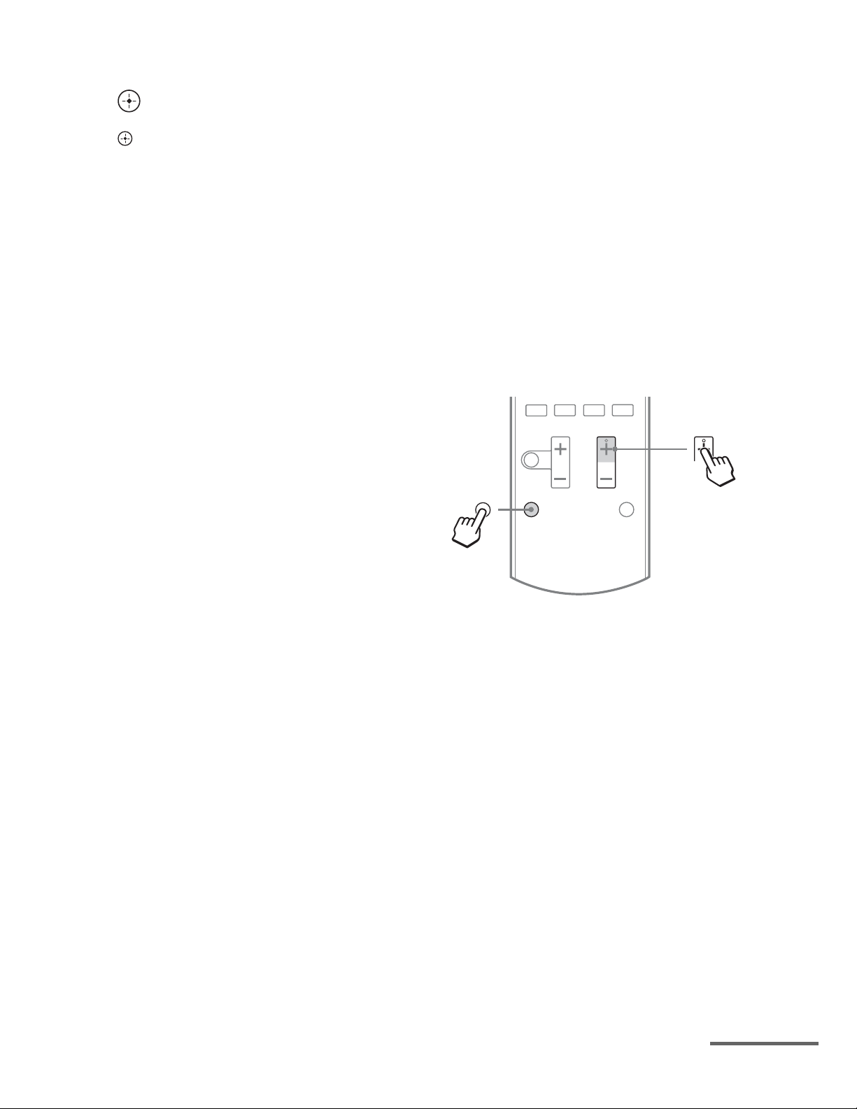
1 While holding down the input
button of which you want to
change the assignment, hold
down AV ?/1.
Example: While holding down SAT/
CATV, hold down AV ?/1.
38
2 With the AV ?/1 button held,
release the input button.
Example: With the AV ?/1 button held,
release SAT/CATV.
US
Page 39

3 Referring to the following table,
press the corresponding
button for the category you
want, then release AV ?/1.
Example: Press 1, then release AV ?/1.
Now you can use the SAT/CATV button
to control the Blu-ray Disc player.
Categories Press
Using the setting menu
You can customize the receiver by making
various adjustments with settings menu.
Navigating through menus
Blu-ray Disc player
(command mode BD1)
Blu-ray Disc recorder
(command mode BD3)
DVD player
(command mode DVD1)
DVD recorder
(command mode DVD3)
VCR (command mode VTR3)
CD player 6
e)
DSS
a)
The default setting of the BD/DVD button.
b)
For details on the BD1 or BD3 setting, refer to the
operating instructions supplied with the Blu-ray
Disc player or Blu-ray Disc recorder.
c)
Sony DVD recorders are operated with a DVD1 or
DVD3 setting. For details, refer to the operating
instructions supplied with the DVD recorders.
d)
The default setting of the VIDEO button.
e)
The default setting of the SAT/CATV button.
a)b)
b)
c)
1
2
3
4
d)
5
7
Resetting the remote control
While holding down MASTER VOL –, press
?/1 and INPUT.
The remote control is reset to the default
settings.
AMP
MENU
,
V/v/B/b
RETURN/
EXIT O
O
MENU
1 Press AMP MENU.
2 Press V/v repeatedly until the
menu item you want appears,
then press or b.
3 Press V/v repeatedly until the
parameter you want to adjust
appears, then press or b.
4 Press V/v repeatedly until the
setting you want appears, then
press .
To return to the previous
display
Press B or RETURN/ EXIT O.
To exit the menu
Press AMP MENU.
Advanced Settings
continued
39
US
Page 40

Overview of the menus
You can set the following items using the
AMP MENU.
The default settings are underlined.
AMP MENU
a)
AUTO CAL
LEVEL TEST TONE AUTO xxx
SPEAKER CENTER SP CENTER YES
A.CAL START
OFF
FL LEVEL FL +6.0,…
,...
FL 0
FL -6.0
FR LEVEL FR +6.0,…
FR 0
,...
FR -6.0
c)
d)
d)
c)
CNT +6.0,...
CNT 0
,...
CNT -6.0
SL +6.0,…
,...
SL 0
SL -6.0
SR +6.0,…
,...
SR 0
SR -6.0
SW 0
,...
SW -6.0
COMP. STD
COMP. AUTO
COMP. OFF
CENTER NO
SUR NO
FL 9' 10
FL 3' 3"
FR 9' 10
FR 3' 3"
CNT 32' 9",…
CNT 9' 10
CNT 3' 3"
SL 32' 9",….
SL 9' 10
SL 3' 3"
SR 32' 9",…
SR 9' 10
SR 3' 3"
SW 9' 10
SW 3' 3"
",…
",…
",…
",…
",…
CNT LEVEL
SL LEVEL
SR LEVEL
SW LEVEL SW +6.0,…
D. RANGE COMP. MAX
SUR SP SUR YES
FL DIST. FL 32' 9",…
FR DIST. FR 32' 9",…
CNT DIST.
SL DIST.
SR DIST.
SW DIST. SW 32' 9",…
d)
d)
",…
b)
EQ BASS BASS +6,...
BASS 0
BASS -6
TREBLE TREBLE +6,
…TREBLE 0
f)
g)
…TREBLE -6
MONO
SYNC OFF
MAIN
SUB
NIGHT OFF
AUTO
OPT
CTRL OFF
ON
AUTO
ARC ON
ARC OFF
DIM MID
DIM OFF
1-30-00
1-00-00
0-30-00
OFF
STBY OFF
e)
TUNER
AUDIO A/V SYNC SYNC ON
HDMI CTRL HDMI CTRL ON
SYSTEM DIMMER DIM MAX
a)
For details, see “2: Performing Auto Calibration”
FM MODE STEREO
NAME IN
DUAL MONO MAIN/SUB
NIGHT MODE NIGHT ON
INPUT MODE
PASS THRU
g)h)
ARC
SLEEP 2-00-00
AUTO STBY STBY ON
,...
(page 25).
b)
xxx represent a speaker channel (FL, CNT, FR,
SR, SL, SW).
c)
This parameter is only available when “CENTER
SP” is set to “CENTER YES”.
d)
This parameter is only available when “SUR SP”
is set to “SUR YES”.
e)
This parameter is only available when TUNER
input is selected.
f)
This parameter is only available when SAT/CATV
input is selected.
g)
This parameter is only available when “CTRL
HDMI” is set to “CTRL ON”.
h)
For details, see “Enjoying the TV sound via an
HDMI cable (Audio Return Channel)” (page 37).
,
40
US
Page 41

LEVEL menu
You can adjust the level of each speaker to suit
your preference.
To output a test tone from each
speaker
You can output a test tone from the speakers in
sequence.
• AUTO FL, AUTO CNT, AUTO FR, AUTO
SR, AUTO SL, AUTO SW
•OFF
Tip
Audio dynamic range compression lets you
compress the dynamic range of the soundtrack based
on the dynamic range information included in the
Dolby Digital signal.
“COMP. STD” is the standard setting, but it only
enacts light compression. Therefore, we recommend
using the “COMP. MAX” setting. This greatly
compresses the dynamic range and lets you view
movies late at night at low volumes. Unlike analog
limiters, the levels are predetermined and provide a
very natural compression.
SPEAKER menu
When a test tone is not output from
the speakers
• The speaker cords may not be connected
securely.
• The speaker cords may have the short-circuit
problem.
Note
The test tone signals are not output from the HDMI
TV OUT jack.
To adjust the speaker levels
You can adjust each speaker level (FL
LEVEL, FR LEVEL, CNT LEVEL, SL
LEVEL, SR LEVEL, SW LEVEL) from –6.0
dB to +6.0 dB in 0.5 dB interval.
Enjoying Dolby Digital sound at
low volume (D. RANGE)
Narrows the dynamic range of the sound track.
Useful for enjoying movies at low volume.
D. RANGE only applies to Dolby Digital
sources.
• COMP. MAX: Compress dynamic range
fully.
• COMP. STD: Compress dynamic range as
intended by the recording engineer.
• COMP. AUTO: Compress dynamic range
automatically.
• COMP. OFF: Does not compress dynamic
range.
You can adjust the distance of the speakers
connected to this receiver.
To set the speaker connection
• CENTER (SUR) YES: Selects when you
connect the speaker.
• CENTER (SUR) NO: Selects when you do
not connect the speaker.
To set the speaker distance
You can adjust each speaker distance (FL
DIST, FR DIST, CNT DIST, SL DIST, SR
DIST, SW DIST) from 3' 3" to 32' 9" in 1 inch
interval.
EQ menu
You can adjust the equalizer (bass and treble
level) of the front speakers from -6 dB to
+6 dB in 1 dB interval.
xBASS
xTREBLE
Advanced Settings
41
US
Page 42

TUNER menu
You can set the FM station receiving mode and
name the preset stations.
x FM MODE
• STEREO: This receiver will decode the
signal as stereo signal when the radio station
is broadcast in stereo.
• MONO: This receiver will decode the signal
as mono signal regardless of the broadcast
signal.
x NAME IN
Lets you set the name of preset stations. For
details, see “Naming preset station” (page 32).
x DUAL MONO
Lets you select the language you want when
you listen to the dual audio of a digital
broadcast when available. This feature only
functions for Dolby Digital sources.
• MAIN / SUB: Outputs sound of the main
language through the front left speaker and
sound of the sub language through the front
right speaker simultaneously.
• MAIN: Outputs sound of the main language.
• SUB: Outputs sound of the sub language.
x NIGHT MODE
Lets you retain a theater-like environment at
low volume levels.
• NIGHT ON
• NIGHT OFF
AUDIO menu
You can adjust settings for the audio to suit
your preference.
x A/V SYNC
Lets you delay the output of audio to minimize
the time gap between audio output and visual
display.
• SYNC ON: The audio output is delayed so
that the time gap between the audio output
and visual display is minimized.
• SYNC OFF: The audio output is not
delayed.
Notes
• You may not be able to adjust the delay between
sound and image perfectly using this function.
• This parameter is useful when you use a large LCD
or plasma monitor or a projector.
• The delay time may vary depending on audio
format, sound field, and speaker distance settings.
Tip
While this function is on, the bass, treble, and effect
levels increase, and “D. RANGE” is automatically
set to “COMP. MAX”.
x INPUT MODE
Lets you select the audio input mode setting
when you connect satellite tuner or cable TV
tuner to both HDMI IN jack and optical digital
input jack on the receiver and SAT/CATV
input has been selected.
• AUTO: Gives priority to HDMI audio
signals if there are both digital (HDMI and
optical) connections.
• OPT: Specifies the digital audio signals
input to the SAT/CATV OPT IN jack.
42
US
Page 43

HDMI menu SYSTEM menu
You can make various adjustments for HDMI
settings.
x CTRL HDMI
Lets you turn the Control for HDMI function
on or off. For details, see ““BRAVIA” Sync
Features” (page 34).
x PASS THRU
Lets you output the HDMI signals to the TV
even when the receiver is in standby mode.
• ON: The receiver continuously outputs
HDMI signals from the receiver’s HDMI
TV OUT jack.
• AUTO: When the TV is turned on while the
receiver is in the standby mode, the receiver
outputs HDMI signals from the receiver’s
HDMI TV OUT jack. Sony recommends
this setting if you use a “BRAVIA” Sync
compatible Sony TV. This setting saves
power in the standby mode when compared
with the “ON” setting.
Notes
• The power saving function may not work for some
TVs compatible with the “BRAVIA” Sync. If this
is the case, set “PASS THRU” to “ON”.
• Depending on your equipment, it may take time
before image or sound is output.
You can customize the settings of the receiver.
x DIMMER
Lets you adjust the brightness of the display
panel in 3 levels.
• DIM MAX
•DIM MID
• DIM OFF
x SLEEP
Lets you set the receiver to turn off
automatically at a specified time.
• 2-00-00
• 1-30-00
• 1-00-00
• 0-30-00
•OFF
When Sleep Timer is being used, “SLEEP”
indicator lights up on the display panel.
Tip
To check the remaining time before the receiver
turns off, select “SLEEP” using the AMP MENU.
The remaining time appears on the display panel. To
cancel the Sleep Timer, select “OFF”.
x AUTO STBY
Lets you set the receiver switch to standby
mode automatically when you do not operate
the receiver or when there is no signals input to
the receiver.
• STBY ON: Switches to standby mode after
approximately 30 minutes.
• STBY OFF: Does not switch to standby
mode.
Advanced Settings
Notes
• This function does not work when TUNER input is
selected.
• If you use the Auto Standby mode and the Sleep
Timer at the same time, the Sleep Timer has
priority.
US
43
Page 44

Additional Information
Precautions
On safety
Should any solid object or liquid fall into the
cabinet, unplug the receiver and have it
checked by qualified personnel before
operating it any further.
On power sources
• Before operating the receiver, check that the
operating voltage is identical with your local
power supply.
The operating voltage is indicated on the
nameplate on the back of the receiver.
• The unit is not disconnected from the AC
power source (mains) as long as it is
connected to the wall outlet, even if the unit
itself has been turned off.
• If you are not going to use the receiver for a
long time, be sure to disconnect the receiver
from the wall outlet. To disconnect the AC
power cord (mains lead), grasp the plug
itself; never pull the cord.
• (USA model only)
One blade of the plug is wider than the other
for the purpose of safety and will fit into the
wall outlet only one way. If you are unable
to insert the plug fully into the outlet, contact
your dealer.
• The AC power cord (mains lead) must be
changed only at a qualified service shop.
On heat buildup
Although the receiver heats up during
operation, this is not a malfunction. If you
continuously use this receiver at a large
volume, the cabinet temperature of the top,
side and bottom rises considerably. To avoid
burning yourself, do not touch the cabinet.
On placement
• Place the receiver in a location with
adequate ventilation to prevent heat buildup
and prolong the life of the receiver.
• Do not place the receiver near heat sources,
or in a place subject to direct sunlight,
excessive dust, or mechanical shock.
• Do not place anything on top of the cabinet
that might block the ventilation holes and
cause malfunctions.
• Do not place the receiver near equipment
such as a TV, VCR, or tape deck. If the
receiver is being used in combination with a
TV, VCR, or tape deck, and is placed too
close to that equipment, noise may result,
and picture quality may suffer. This is
especially likely when using an indoor
antenna (aerial). Therefore, we recommend
using an outdoor antenna (aerial).
• Use caution when placing the receiver or
speakers on surfaces that have been
specially treated (with wax, oil, polish, etc.)
as staining or discoloration of the surface
may result.
On operation
Before connecting other equipment, be sure to
turn off and unplug the receiver.
If you encounter color
irregularity on a nearby TV
screen
The center speaker is magnetically shielded to
allow it to be installed near a TV set. However,
color irregularities may still be observed on
certain types of TV sets. As the front speakers,
surround speakers and subwoofer are not
magnetically shielded, we recommend that
you place them slightly further away from TV
set (page 15).
If color irregularity is
observed...
Turn off the TV set, then turn it on again after
15 to 30 minutes.
44
US
Page 45

If color irregularity is observed
again...
Place the speaker further away from the TV
set.
If howling occurs
Reposition the speakers or turn down the
volume on the receiver.
On cleaning
• Clean the cabinet, panel, and controls with a
soft dry cloth. Do not use any type of
abrasive pad, scouring powder, scrubbing
brush or sponge.
• If it is stained with oil or fingerprints, breath
on the surface and wipe it with soft dry cloth.
If you have any questions or problems
concerning your receiver, please consult your
nearest Sony dealer.
Troubleshooting
Sound
Dolby Digital or DTS multi channel
sound is not reproduced.
• Check that the DVD, etc. you are playing
is recorded in Dolby Digital or DTS
format.
• When connecting the DVD player, etc., to
the digital input jacks of this receiver,
check the audio output setting of the
connected equipment.
• Use the TV menu to set the Speaker
Setting to Audio System.
• Make sure “CTRL HDMI” is set to
“CTRL OFF” in HDMI menu.
The surround effect cannot be
obtained.
• Make sure you have selected the sound
field for movie or music mode (page 33).
• Sound fields do not function when DTSHD Master Audio, DTS-HD High
Resolution Audio or Dolby TrueHD with
sampling frequency of more than 48 kHz
are being received.
If you experience any of the following
difficulties while using the receiver, use this
troubleshooting guide to help you remedy the
problem. Should any problem persist, consult
your nearest Sony dealer. Note that if service
personnel changes some parts during repair,
these parts may be retained.
Power
The receiver is turned off
automatically.
• “AUTO STBY” is set to “STBY ON”
(page 43).
• The sleep timer function is working (page
43).
There is no sound, or only a very low
level sound is heard from the specified
speakers.
• Make sure you have connected to both the
L and R jacks of an analog equipment,
analog equipment requires both L and R
jack connections. Use an audio cord (not
supplied).
• Check that the speakers are connected
securely.
• Check that the subwoofer is connected
correctly and securely.
• Adjust the speaker level (page 41).
Additional Information
continued
45
US
Page 46

There is no sound from a specific
equipment.
• Check that the equipment is connected
correctly to the audio input jacks for that
equipment.
• Check that the cord(s) used for the
connection is (are) fully inserted into the
jacks on both the receiver and the
equipment.
• Check that the equipment is connected
correctly to the HDMI jack for that
equipment.
• Make sure “CTRL HDMI” is set to
“CTRL ON” in HDMI menu.
• You cannot listen to the Super Audio CD
by connecting HDMI.
• Depending on the playback equipment,
you may need to set up the HDMI setting
of the equipment. Refer to the operating
instructions supplied with each
equipment.
• Be sure to use a High Speed HDMI cable
when you view images or listen to sound,
especially for the 1080p, Deep Color
(Deep Colour) or 3D transmission.
There is no sound, no matter which
equipment is selected, or only a very
low-level sound is heard.
• Check that all connecting cords are
inserted to their input/output jacks for the
respective jacks of the receiver, speakers
and the equipment.
• Check that both the receiver and all
equipment are turned on.
• Check that MASTER VOLUME is not set
to “VOL MIN”.
• Press MUTING to cancel the muting
function.
• Check that you have selected the correct
equipment with the input buttons.
• The protective device on the receiver has
been activated. Turn off the receiver,
eliminate the short-circuit problem, and
turn on the power again.
• Check that the INPUT MODE setting is
correct for SAT/CATV input.
There is severe hum or noise.
• Check that the speakers and equipment are
connected securely.
• Check that the connecting cords are away
from a transformer or motor, and at least
3 meters (10 feet) away from a TV set or
fluorescent light.
• Move your audio equipment away from
the TV.
• The plugs and jacks are dirty. Wipe them
with a cloth slightly moistened with
alcohol.
There is no sound from digital sources
(from OPTICAL input jack).
• Check that the INPUT MODE is set to
“OPT” for SAT/CATV input (page 42).
• Set “ARC” to “ARC OFF” when no sound
is output from TV OPT IN jack during TV
input.
When the receiver is in standby mode,
there is no sound output from the TV.
• When the receiver enters into standby
mode, the sound is from the last HDMI
equipment selection before you turned off
the receiver. If you are enjoying other
equipment, play the equipment and
perform the One-Touch Play operation, or
turn on the receiver to select the HDMI
equipment you want to enjoy.
• Make sure “PASS THRU” is set to “ON”
in the HDMI menu if you connect
equipment not compatible with the
“BRAVIA” Sync to the receiver (page 43).
46
US
Page 47

No sound is output from the receiver
and TV speaker.
• Check that the equipment is connected
correctly to the HDMI jack for that
equipment.
• Make sure “CTRL HDMI” is set to
“CTRL ON” in HDMI menu.
• You cannot listen to the Super Audio CD
by connecting HDMI.
• Depending on the playback equipment,
you may need to set up the HDMI setting
of the equipment. Refer to the operating
instructions supplied with each
equipment.
• Be sure to use a High Speed HDMI cable
when you view images or listen to sound,
especially for the Deep Color (Deep
Colour) or 3D transmission.
• Make sure the TV is compatible with the
System Audio Control function.
• If you cannot listen to the sound of the
equipment connected to the receiver while
TV input is selected
– Be sure to change the input of the
receiver to HDMI when you want to
watch a program on the equipment
connected via HDMI connection to the
receiver.
– Change the TV channel when you want
to watch a TV broadcast.
– Be sure to select the correct equipment
or input you want when you watch a
program from the equipment connected
to the TV. Refer to the operating
instructions of the TV on this operation.
There is no sound from the equipment
connected to the DOCK FOR iPod/
iPhone.
• Adjust the volume of this receiver.
• The DOCK FOR iPod/iPhone and/or
equipment is not connected correctly.
Turn off the receiver, then reconnect the
DOCK FOR iPod/iPhone and/or
equipment.
Image
No image appears on the TV.
• Make sure you have connected the video
output of your video equipment to the TV.
• Move your audio equipment away from
the TV.
• Make sure you have connected the video
output of your DOCK FOR iPod/iPhone to
the TV.
• Check that the equipment is connected
correctly to the HDMI jack for that
equipment.
• Depending on the playback equipment,
you may need to set up the equipment.
Refer to the operating instructions
supplied with each equipment.
• Be sure to use a High Speed HDMI cable
when you view images or listen to sound,
especially for the 1080p, Deep Color
(Deep Colour) or 3D transmission.
When the receiver is in standby mode,
there is no image output from the TV.
• When the receiver enters into standby
mode, the image is from the last HDMI
equipment selection before you turned off
the receiver. If you are enjoying other
equipment, play the equipment and
perform the One-Touch Play operation, or
turn on the receiver to select the HDMI
equipment you want to enjoy.
• Make sure “PASS THRU” is set to “ON”
in the HDMI menu if you connect
equipment not compatible with the
“BRAVIA” Sync to the receiver (page 43).
No 3D image appears on the TV.
• Depending on the TV or the video
equipment, 3D images may not be
displayed.
Additional Information
47
US
Page 48

Tuner
Others
The FM reception is poor.
• Use a 75-ohm coaxial cable (not supplied)
to connect the receiver to an outdoor FM
antenna (aerial) as shown below.
Outdoor FM antenna (aerial)
Receiver
ANTENNA
Radio stations cannot be tuned in.
• Check that the antennas are connected
securely. Adjust the antennas and connect
an external antenna (aerial), if necessary.
• The signal strength of the stations is too
weak with automatic tuning. Change to
monaural reception (page 30).
• No stations have been preset or the preset
stations have been cleared (when tuning
by scanning preset stations is used). Preset
the stations (page 31).
Remote control
The Control for HDMI function does not
work.
• Check the HDMI connection (page 19).
• Make sure “CTRL HDMI” is set to
“CTRL ON” in HDMI menu.
• Make sure the connected equipment is
compatible with the Control for HDMI
function.
• Check the Control for HDMI settings on
the connected equipment. Refer to the
operating instructions of the connected
equipment.
• The types and the number of equipment
which can be controlled by the
“BRAVIA” Sync are restricted in the
HDMI CEC standard as follows.
– Recording equipment (Blu-ray Disc
recorder, DVD recorder, etc.): up to 3
equipment
– Playback equipment (Blu-ray Disc
player, DVD player, etc.): up to 3
equipment
– Tuner-related equipment: up to 4
equipment
– AV receiver (audio system): up to 1
equipment
The remote control does not function.
• Point the remote control at the remote
control sensor on the receiver.
• Remove any obstacles in the path between
the remote control and the receiver.
• Replace all the batteries in the remote
control with new ones, if they are weak.
• Make sure you select the correct input on
the remote control.
US
48
The TV’s remote control cannot be
used to control the connected
equipment when using the Control for
HDMI function.
• Depending on the connected equipment
and TV, you may need to set up the
equipment and TV. Refer to the operating
instructions supplied with each equipment
and TV.
• Change the input of the receiver to the
HDMI input connected to the equipment.
Page 49

Error messages
If there is a malfunction, a message appears on
the display panel. You can check the condition
of the system by the message. If any problem
persists, consult your nearest Sony dealer.
If an error message appears while you perform
Auto Calibration, see “When error codes
appear” (page 27) to solve the problem.
PROTECTOR
Irregular current is output to the speakers,
the volume level is too high, or the upper
panel of the receiver is covered and
ventilation holes are blocked. The receiver
will automatically turn off after a few
seconds. Check the speaker connection and
remove the object covering the ventilation
holes.
Turn on the power and increase the volume
level.
Clearing the memory
If you are unable to remedy the problem using
the troubleshooting guide, clearing the
receiver’s memory may remedy the problem.
However, note that all memorized settings will
be reset to the default settings and you will
have to readjust all settings on the receiver.
Reference sections
Specifications
AUDIO POWER
SPECIFICATIONS
Amplifier section
POWER OUTPUT AND TOTAL
HARMONIC DISTORTION:
(FTC)
(USA model only)
FRONT L + FRONT R
With 3 ohm loads, both
channels driven, from 180
– 20,000 Hz; rated 84 watts
per channel minimum
RMS power, with no more
than 1% total harmonic
distortion from 250
milliwatts to rated output.
POWER OUTPUT (reference)
FRONT L/FRONT R/CENTER/SUR L/SUR R
167 W (per channel at
3 ohms, 1 kHz)
SUBWOOFER 165 W (at 3 ohms, 60 Hz)
Inputs
Analog Sensitivity: 1 V/50 kohms
Digital (Coaxial) Impedance: 75 ohms
FM tuner section
Tuning range 87.5 MHz – 108.0 MHz
(100 kHz step)
Antenna FM wire antenna (aerial)
Antenna terminals 75 ohms, unbalanced
Additional Information
To clear See
All memorized settings page 24
General
Power requirements 120 V AC, 60 Hz
Power output (DMPORT)
DC OUT: 5 V, 1 A MAX
Power consumption 110 W
Power consumption (during standby mode)
0.3 W (When Control for
HDMI is set to off)
continued
49
US
Page 50

Dimensions (w/h/d) (Approx.)
430 mm × 65 mm ×
306 mm
(17 in × 2 5/8 in ×
12 1/8 in)
including projecting parts
and controls
Mass (Approx.) 3.0 kg (6 lb 10 oz)
Speaker section
• Front/Surround speaker (SS-TSB105)
• Center speaker (SS-CTB102)
Front/Surround speaker
Full range
Center speaker Full range, magnetically
shielded
Speaker unit
Front/Surround speaker
55 mm × 80 mm (2 1/4 in ×
3 1/4 in), cone type
Center speaker 30 mm × 60 mm (1 3/16 in
× 2 3/8 in), cone type
Enclosure type
Front/Surround speaker
Bass reflex
Center speaker Acoustic suspension
Rated impedance 3 ohms
Dimension (w/h/d) (Approx.)
Front/Surround speaker
85 mm × 220 mm × 95 mm
(3 3/8 in × 8 3/4 in ×
3 3/4 in) (with foot)
Center speaker 315 mm × 55 mm × 60 mm
(12 1/2 in × 2 1/4 in ×
2 3/8 in) (with foot)
Mass (Approx.)
Front speaker 0.46 kg (1 lb 1 oz)
(with foot)
Center speaker 0.31 kg (11 oz) (with foot)
Surround speaker 0.53 kg (1 lb 3 oz)
(with foot)
• Subwoofer (SS-WSB103)
Speaker unit 160 mm (6 3/8 in),
cone type
Enclosure type Bass reflex
Rated impedance 3 ohms
Dimensions (w/h/d) (Approx.)
260 mm × 265 mm ×
270 mm (10 1/4 in ×
10 1/2 in × 10 3/4 in)
(with foot)
Mass (Approx.) 3.6 kg (7 lb 15 oz)
(with foot)
Design and specifications are subject to
change without notice.
Halogenated flame retardants are not used in
the certain printed wiring boards.
50
US
Page 51

Index
Numerics
2 channel sound mode 32
5.1 channel 15
A
A.F.D. MODE 32
A/V SYNC 42
Audio Return Channel
(ARC) 37
Auto Calibration 24
AUTO STBY 43
B
Blu-ray Disc player
connecting 21
“BRAVIA” Sync
preparing 35
C
Cable TV tuner
connecting 21
CD player
connecting 22
Clear
memory 49
Control for HDMI 35
D
DIMMER 43
DOCK FOR iPod/iPhone
connecting 22
DVD player
connecting 21
I
Initial setup 24
INPUT MODE 42
M
Menu
AUDIO 40
AUTO CAL 40
EQ 40
HDMI 40
LEVEL 40
SPEAKER 40
SYSTEM 40
Movie mode 33
Music mode 33
Muting 28
N
Naming 32
NIGHT MODE 42
O
One-Touch Play 36
P
Playback 28
PlayStation 3
connecting 21
PROTECTOR 49
R
Remote control 10
S
Satellite tuner
connecting 21
Scene Select 38
SLEEP 43
Sound fields
selecting 32
Speakers
connecting 17
installing 15
Super Audio CD player
connecting 22
System Audio Control 36
System Power-Off 37
T
TEST TONE 40
Theatre/Theater Mode Sync
38
Tuner
connecting 23
Tuning
automatically 30
directly 30
to preset stations 31
TV
connecting 18
V
VCR
connecting 21
Additional Information
E
Error messages 49
F
FM Mode 42
H
HDMI
connecting 19
51
US
Page 52

Sony Corporation Printed in Malaysia
(1)
Page 53

4-264-480-11(1)
(1)
HT-SS380
For details, refer to the supplied Operating Instructions./
Quick Setup Guide/ Guía de instalación rápida
Sony Corporation © 2011 Printed in Malaysia
Installing and connecting the speakers/ Instalación y conexión de los altavoces
1
Connect the speaker cords to match the color of the SPEAKERS jacks of the receiver./
Conecte los cables de altavoz procurando que coincidan con los colores de las tomas SPEAKERS (altavoces) del
receptor.
Para obtener más información, consulte el Manual de instrucciones suministrado.
FRONT R SUR R SUBWOOFER
FRONT L
SUBWOOFER
SUR L
FRONT R
CENTER
SUR R
SPEAKERS
FRONT L
SUR R
FRONT R
FRONT L SUR L CENTER
SUR L
SUBWOOFER
CENTER
Page 54

Connecting other equipment/ Conexión de otros equipos
2
If your TV is compatible with Audio Return Channel (ARC) function, this connection is not needed./
Si su televisor es compatible con la función de Canal de Retorno de Audio (ARC), esta conexión no es necesaria.
AUDIO IN
COAX IN
OPT IN
OPT IN
VIDEO
SAT/CATV
SPEAKERS
SUR R SUR L CENTER
FRONT R FRONT L
The cords used for connection are not supplied./
Los cables utilizados para la conexión no se suministran.
SUBWOOFER
TV
DIGITAL LINE IN ANTENNA
R
L
AUTO
CAL MIC
DC5V
1 A MAX
DMPORT
HDMI
GAME IN BD/DVD IN SAT/CATV IN
TV/Televisor
TV OUT
Preparing the receiver/ Preparación del
3
receptor
1
ARC
2
?/1 : on/standby / encendido/en espera
3
INPUT
DOCK FOR iPod/iPhone (supplied)/
DOCK FOR iPod/iPhone (suministrado)
Using AUTO CALIBRATION/ Utilización de AUTO CALIBRATION (calibración automática)
4
A
AUDIO IN
COAX IN
OPT INTVOPT IN
VIDEO
SAT/CATV
DIGITAL
LINE IN ANTENNA
AUTO
CAL MIC
L
DC5V
1 A MAX
R
AUTO
CAL MIC
ARC
HDMI
SAT/CATV IN
GAME IN BD/DVD IN
TV OUT
DMPORT
SPEAKERS
FRONT R FRONT L
SUR R SUR L CENTERSUBWOOFER
Optimizer microphone (supplied)/
Micrófono optimizador (suministrado)
PlayStation 3/
PlayStation 3
B
Blu-ray Disc player, DVD player/
Reproductor de discos Blu-ray,
Lector de DVD
Press/ Pulse
1 AMP MENU
2
0
3 p/
4
Satellite tuner, cable TV tuner/
Sintonizador de satélite,
Decodifi cador de televisión por cable
j/
The Auto Calibration function starts./ Se iniciará la función de Calibración automática.
v
Display panel/ Pantalla
5 4 3 2 1
è
*
TONE
è
T S P
è
WOOFER
* For details on error codes, refer “When error codes appear” in “Using AUTO
CALIBRATION” in the Operating Instructions./
Para obtener más información sobre los códigos de error, consulte “Cuando
aparecen códigos de error” en “Utilización de AUTO CALIBRATION
*
(calibración automática)” en el Manual de instrucciones.
è
SAVE EXIT
Display panel/ Pantalla
Select/ Seleccionar
AUTO CAL
Select/ Seleccionar
A.CAL START
C
0
v
“COMPLETE” appears on the display panel./
Aparece “COMPLETE” en la pantalla.
Page 55

Page 56

Page 57

Page 58

Page 59

Page 60

Page 61

Page 62

Page 63

Page 64

Page 65

Page 66

Page 67

Page 68

Page 69

Page 70

Page 71

Page 72

Page 73

Page 74

4-557-172-03
General Stereo/Hifi Components/Tape Decks
®
CD Players/Mini Disc Players/Audio Systems
Hifi Audio
LIMITED WARRANTY (U.S. Only)
Sony Electronics Inc. (“Sony”) warrants this product against defects in material or workmanship for the time
periods and as set forth below. Pursuant to this Limited Warranty, Sony will, at its option, (i) repair the product
using new or refurbished parts or (ii) replace the product with a new or refurbished product. For purposes of this
Limited Warranty , “refurbished” means a product or part that has been returned to its original specifications. In
the event of a defect, these are your exclusive remedies.
Labor: For a period of one (1) year from the original date of purchase of the product (“Labor Warranty”), Sony
will, at its option, repair or replace with new or refurbished product, product determined to be defective. If Sony
elects to replace the product after this Labor Warranty has expired but while the Parts W arranty below is still in
effect, it will do so for the applicable labor charge.
Parts: For a period of one (1) year from the original date of purchase of product (“Parts Warranty”), Sony will
supply new or refurbished replacement parts in exchange for parts determined to be defective.
This Limited Warranty covers only the hardware components packaged with the Product. It does not cover
technical assistance for hardware or software usage and it does not cover any software products whether or not
contained in the Product; any such software is provided “AS IS” unless expressly provided for in any enclosed
software Limited Warranty . Please refer to the End User License Agreements included with the Product for your
rights and obligations with respect to the software.
Instructions: To obtain warranty service, you must deliver the product, freight prepaid, in either its original
packaging or packaging affording an equal degree of protection to the Sony authorized service facility specified.
It is your responsibility to backup any data, software or other materials you may have stored or preserved on your unit. It is likely that such data, software, or other materials will be lost or reformatted
during service and Sony will not be responsible for any such damage or loss. A dated purchase receipt is
required. For specific instructions on how to obtain warranty service for your product,
Visit Sony’ s W eb Site:
www.sony.com/service
Or call the Sony Customer Information Service Center
1-800-222-SONY (7669)
For an accessory or part not available from your authorized dealer , call:
1-800-488-SONY (7669)
Repair / Replacement Warranty: This Limited Warranty shall apply to any repair , replacement part or replacement product for the remainder of the original Limited Warranty period or for ninety (90) days, whichever is
longer . Any parts or product replaced under this Limited W arranty will become the property of Sony.
This Limited Warranty only covers product issues caused by defects in material or workmanship during ordinary
consumer use; it does not cover product issues caused by any other reason, including but not limited to product
issues due to commercial use, acts of God, misuse, limitations of technology, or modification of or to any part of
the Sony product. This Limited Warranty does not cover Sony products sold AS IS or WITH ALL FAULTS or
consumables (such as fuses or batteries). This Limited Warranty is invalid if the factory-applied serial number
has been altered or removed from the product. This Limited Warranty is valid only in the United States.
LIMITATION ON DAMAGES: SONY SHALL NOT BE LIABLE FOR ANY INCIDENTAL OR CONSEQUENTIAL
DAMAGES FOR BREACH OF ANY EXPRESS OR IMPLIED WARRANTY ON THIS PRODUCT.
DURATION OF IMPLIED WARRANTIES: EXCEPT TO THE EXTENT PROHIBITED BY APPLICABLE LAW, ANY
IMPLIED WARRANTY OF MERCHANT ABILITY OR FITNESS FOR A PARTICULAR PURPOSE ON THIS PRODUCT
IS LIMITED IN DURATION TO THE DURATION OF THIS WARRANTY.
Some states do not allow the exclusion or limitation of incidental or consequential damages, or allow limitations
on how long an implied warranty lasts, so the above limitations or exclusions may not apply to you. This Limited
Warranty gives you specific legal rights and you may have other rights which vary from state to state.
Printed in Japan
 Loading...