

Sony HT-SL800, HT-SL700, HT-SL500, HT-SL600 User Manual

4-254-753-12(1)
Home Theatre
System
Operating Instructions
HT-SL800
HT-SL700
HT-SL600
HT-SL500
©2004 Sony Corporation
WARNING
To prevent fire or shock hazard, do not
expose the unit to rain or moisture.
To prevent fire, do not cover the ventilation of the
apparatus with newspapers, table-cloths, curtains, etc.
And don’t place lighted candles on the apparatus.
To prevent fire or shock hazard, do not place objects
filled with liquids, such as vases, on the apparatus.
Do not install the appliance in a confined space,
such as a bookcase or built-in cabinet.
Don’t throw away batteries with
general house waste; dispose of
them correctly as chemical waste.
Except for customers in Europe
ENERGY STAR® is a U.S. registered
mark. As an E
NERGY STAR
Sony Corporation has determined that
this product meets the E
®
TAR
guidelines for energy
S
efficiency.
®
partner,
NERGY
GB
2
About This Manual
• The instructions in this manual are for model
HT-SL800, HT-SL700, HT-SL600 and HT-SL500.
Check your model number by looking at the lower
right corner of the front panel. In this manual,
HT-SL500 models of area code CEL is used for
illustration purposes unless stated otherwise.
• The instructions in this manual describe the controls
on the remote. You can also use the controls on the
receiver if they have the same or similar names as
those on the remote. For details on the use of your
remote, see pages 31–34.
The HT-SL800 consists of:
• Receiver STR-KSL600
• Speaker system
– Front speakers SS-SLP701
– Center speaker SS-CNP501
– Surround speakers SS-MSP501
– Sub woofer SA-WMSP601
The HT-SL700 consists of:
• Receiver STR-KSL700
• Speaker system
– Front speakers SS-SLP701
– Center speaker SS-CNP501
– Surround speakers SS-MSP501
– Sub woofer SA-WMSP501
The HT-SL600 consists of:
• Receiver STR-KSL600
• Speaker system
– Front/Surround speakers SS-MSP501
– Center speaker SS-CNP501
– Sub woofer SA-WMSP601
The HT-SL500 consists of:
• Receiver STR-KSL500
• Speaker system
– Front/Surround speakers SS-MSP501
– Center speaker SS-CNP501
– Sub woofer SA-WMSP501
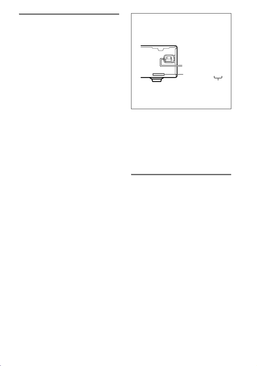
About area codes
The area code of the receiver you purchased is
shown on the lower portion of the rear panel (see
the illustration below).
4-XXX-XXX-XX AA
Area code
Any differences in operation, according to the area
code, are clearly indicated in the text, for example,
“Models of area code AA only”.
This receiver incorporates Dolby* Digital and Pro
Logic Surround and the DTS** Digital Surround
System.
* Manufactured under license from Dolby
Laboratories.
“Dolby”, “Pro Logic” and the double-D symbol are
trademarks of Dolby Laboratories.
** “DTS” and “DTS Digital Surround” are registered
trademarks of Digital Theater Systems, Inc.
Note for the supplied remote
For RM-U700
The AUX button on the remote is not available
for receiver operation.
GB
3

Table of Contents
Getting Started
1: Check how to hookup your
components....................................... 5
1a: Connecting components with
digital audio output jacks ...........7
1b: Connecting components with
only analog audio jacks .............. 9
2: Connecting the antennas ...................10
3: Connecting speakers .........................11
4: Connecting the AC power cord ........14
5: Setting up the speakers ..................... 15
6: Setting up the sub woofer ................. 16
7: Adjusting the speaker levels and
balance............................................17
— TEST TONE
Amplifier Operation
Selecting the component .......................18
Listening to FM/AM radio....................18
Storing FM stations automatically........19
— AUTOBETICAL
(Models of area code CEL, CEK
only)
Presetting radio stations ........................20
Using the Radio Data System (RDS).... 21
(Models of area code CEL, CEK
only)
About the indications in the display......23
Other Operations
Using the Sleep Timer .......................... 30
Operations Using the Remote
RM-U700
Before you use your remote.................. 31
Remote button description.................... 31
Changing the factory setting of an input
button.............................................. 34
Additional Information
Precautions ........................................... 35
Troubleshooting.................................... 36
Specifications ....................................... 38
List of button locations and reference
pages............................................... 41
Index ..................................................... 43
Enjoying Surround Sound
Using only the front speakers and sub
woofer............................................. 24
— 2CH STEREO
Enjoying higher fidelity sound..............24
Selecting a sound field ..........................25
Advanced Adjustments and
Settings
Customizing sound fields......................27
Adjusting the tone................................. 28
Advanced settings................................. 29
GB
4

Getting Started
1: Check how to hookup your components
Steps 1a through 1b beginning on page 7 describe how to hook up your components to this receiver.
Before you begin, refer to “Connectable components” below for the pages which describe how to
connect each component.
After hooking up all your components, proceed to “2: Connecting the antennas” (page 10).
Connectable components
Component to be connected Page
DVD player
With digital audio output
With analog audio output only
TV monitor
With composite video input only 8, 9
Satellite tuner
With digital audio output
With analog audio output only
VCR 9
a)
Model with a DIGITAL OPTICAL OUTPUT or DIGITAL COAXIAL OUTPUT jack, etc.
b)
Model equipped only with AUDIO OUT L/R jacks, etc.
a)
b)
a)
b)
7–8
7–8
7
7
Getting Started
continued
GB
5

Required cords
The hookup diagrams on the subsequent pages assume the use of the following optional connection
cords (A to E) (not supplied unless indicated).
A Audio cord
White (L)
Red (R)
B Audio/video cord
Yellow (video)
White (L/audio)
Red (R/audio)
C Video cord
Yellow
Notes
• Turn off the power to all components before making any connections.
• Be sure to make connections firmly to avoid hum and noise.
• When connecting an audio/video cord, be sure to match the color-coded pins to the appropriate jacks on the
components: yellow (video) to yellow; white (left, audio) to white; and red (right, audio) to red.
• When connecting optical digital cords, insert the cord plugs straight in until they click into place.
• Do not bend or tie optical digital cords.
D Optical digital cord
E Coaxial digital cord (supplied)
Orange
GB
6
.
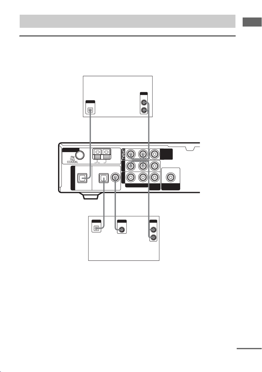
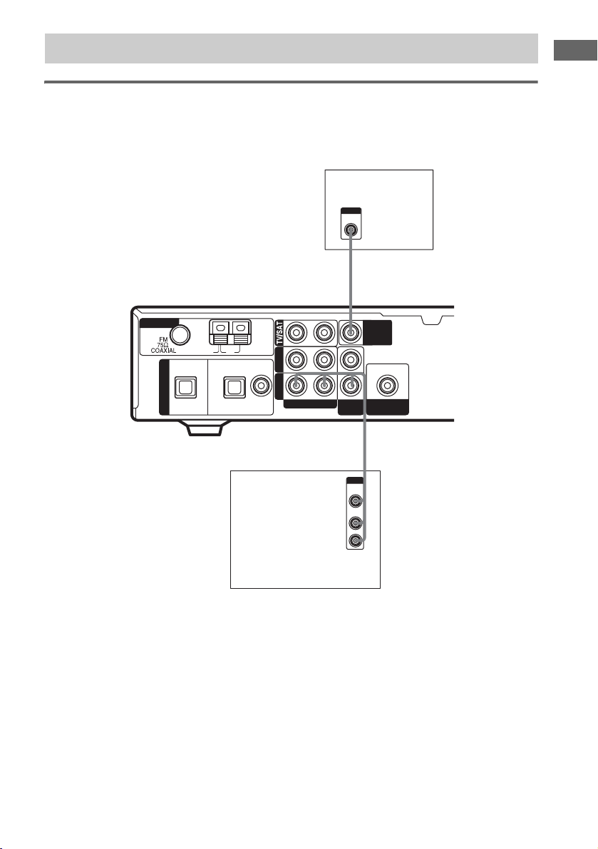
1a: Connecting components with digital audio output jacks
Hooking up a DVD player or satellite tuner
For details on the required cords (A–E), see page 6.
1 Connect the audio jacks.
Satellite tuner
OUTPUT
AUDIO
OUTPUT
DIGITAL
OPTICAL
OUT
L
R
Getting Started
ANTENNA
DIGITAL
OPT IN
TV/SAT
D
U
OUTPUT
OPTICAL
AM
OPT IN COAX IN
DVD
*
D
*
OUTPUT
DIGITAL
COAXIAL
A
DVDVIDEO
AUDIO IN
RL
L
R
VIDEO
IN
AE
OUTPUT
AUDIO
OUT
MONITOR
OUT
OUT
SUB
WOOFER
DVD player
* Connect to either the COAX IN or OPT IN jack. We recommend making connections to the COAX IN jack.
Tip
All the digital audio jacks are compatible with 32 kHz, 44.1 kHz, 48 kHz and 96 kHz sampling frequencies.
continued
GB
7
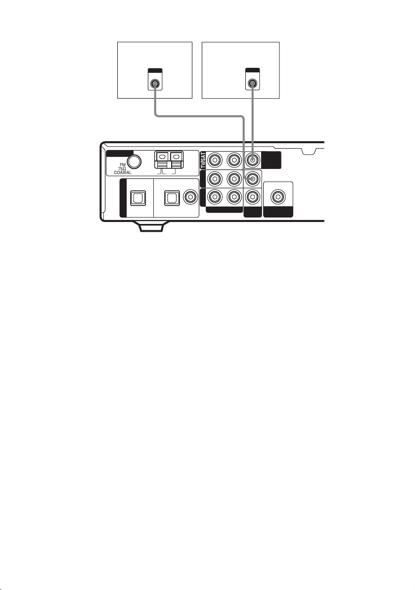
2 Connect the video jacks.
ANTENNA
DIGITAL
DVD player
OUTPUT
OPT IN
TV/SAT
VIDEO
C
U
AM
OPT IN COAX IN
DVD
TV monitor
DVDVIDEO
AUDIO IN
RL
C
VIDEO
INPUT
VIDEO
IN
MONITOR
OUT
OUT
SUB
WOOFER
GB
8
1b: Connecting components with only analog audio jacks
Hooking up video components
If you connect your TV to the MONITOR OUT jack, you can watch the video from the selected input
(page 18). For details on the required cords (A
–E), see page 6.
INPUT
VIDEO
TV monitor
C
Getting Started
ANTENNA
DIGITAL
OPT IN
TV/SAT
U
AM
OPT IN COAX IN
DVD
DVDVIDEO
AUDIO IN
RL
VIDEO
IN
MONITOR
OUT
OUT
SUB
WOOFER
B
OUTPUT
VIDEO
AUDIO
OUT
OUT
L
R
VCR
GB
9
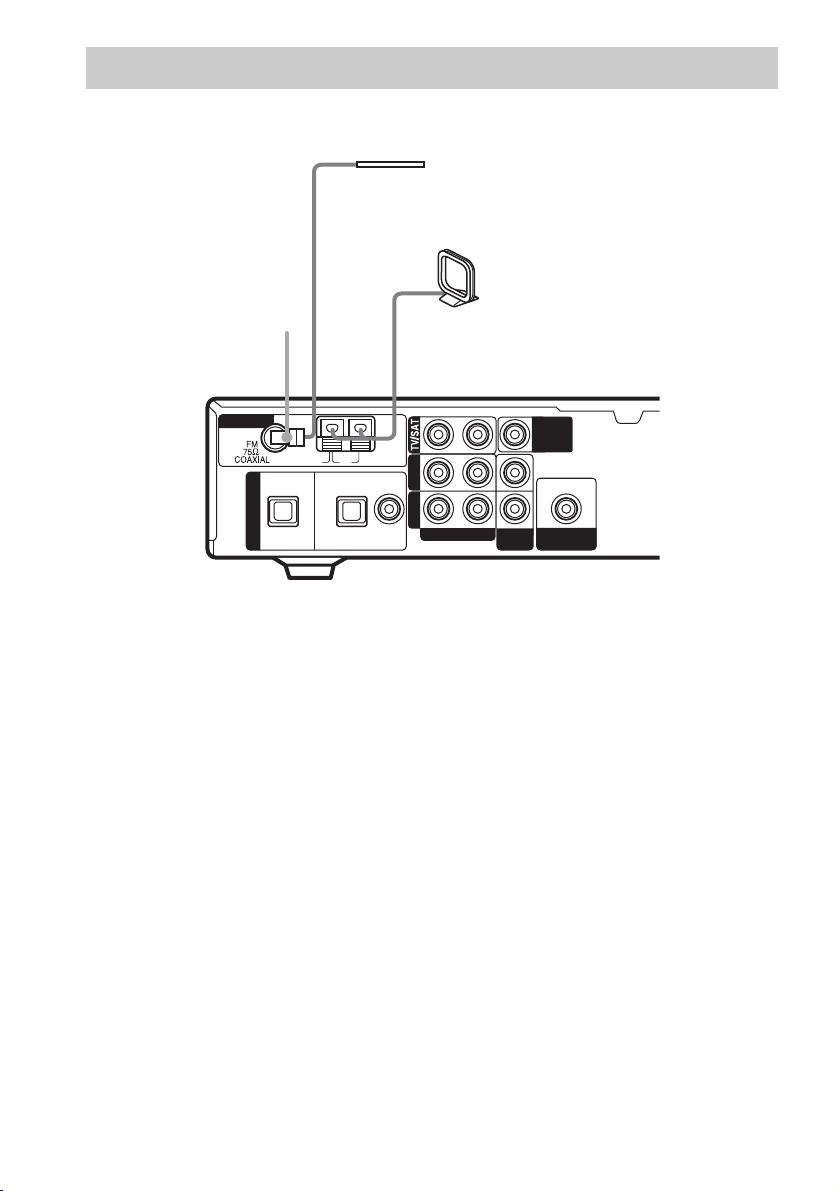
2: Connecting the antennas
Connect the supplied AM loop antenna and FM wire antenna.
FM wire antenna
(supplied)
*
AM loop antenna
(supplied)
ANTENNA
DIGITAL
OPT IN
TV/SAT
U
AM
OPT IN COAX IN
DVD
DVDVIDEO
AUDIO IN
RL
VIDEO
IN
MONITOR
OUT
OUT
SUB
WOOFER
* The shape of connector varies depending on the area code.
Notes
• To prevent noise pickup, keep the AM loop antenna away from the receiver and other components.
• Be sure to fully extend the FM wire antenna.
• After connecting the FM wire antenna, keep it as horizontal as possible.
10
GB
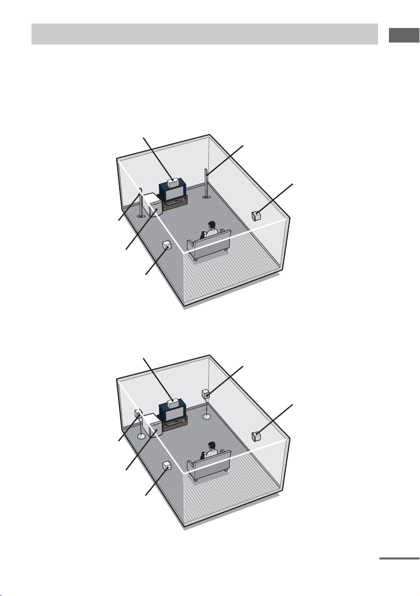
3: Connecting speakers
Connect your speakers to the receiver. This receiver allows you to use a 5.1 channel speaker system.
To fully enjoy theater-like multi channel surround sound requires five speakers (two front speakers, a
center speaker, and two surround speakers) and a sub woofer (5.1 channel).
Example of 5.1 channel speaker system configuration
HT-SL800/HT-SL700 only
Center speaker
Front speaker (Right)
Surround speaker (Right)
Front speaker (Left)
Sub woofer
Surround speaker (Left)
Getting Started
HT-SL600/HT-SL500 only
Center speaker
Front speaker (Left)
Sub woofer
Surround speaker (Left)
Front speaker (Right)
Surround speaker (Right)
continued
11
GB
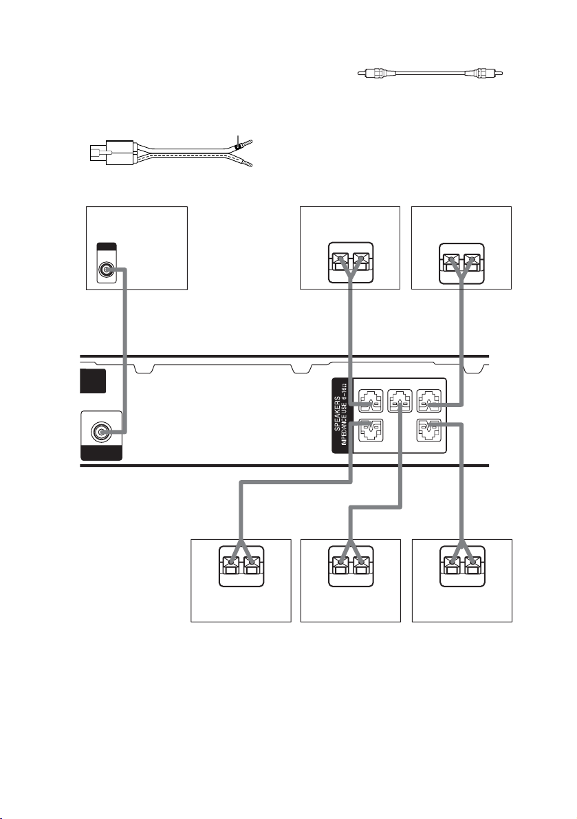
Required cords
A Speaker cords (supplied)
The connector and the colour tube of the speaker
cords are the same colour as the speaker terminal
to be connected.
Colour tube
+
–
B Monaural audio cord (supplied)
Black
INPUT
MONITOR
OUT
OUT
SUB
WOOFER
Subwoofer
B
A
E
Surround speaker
(Right)
e
E
Center speaker
Front speaker
(Right)
Ee
A
FRONT R
CENTER
– + –
– +
SURR R SURR L
A
FRONT L
+
+ –+ –
E
e
Surround speaker
Front speaker
(Left)
Ee
A
A
e
(Left)
Note
Before you connect the speakers, attach the colour labels onto the speakers so that you can identify the speakers to
be connected.
GB
12
Tips
• Since the sub woofer does not emit highly directional
signals, you can place it wherever you want.
• (Except for the front speaker of HT-SL800/
HT-SL700) For greater flexibility in the positioning
of the speakers, use the optional WS-FV11 or WSFV10D floor stand (available only in certain
countries).
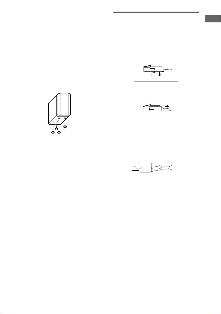
Attaching foot pads
(Except for the front speaker of HT-SL800/
HT-SL700)
To prevent speaker vibration or movement,
attach the supplied foot pads to the speaker as
shown in the illustration below.
Note
Be sure to attach the supplied foot pads to the sub
woofer as well.
To change the speaker cord
If you want to change the speaker cord, you can
detach the supplied speaker cord from the
connector.
1 Press the connector onto a flat surface.
Make sure that the catcher is facing the flat
surface.
catcher
2 Pull the speaker cord from the
connector.
3 Twist the stripped ends of the speaker
cord you want about 10 mm and insert
the speaker cord into the connector.
Make sure that the speaker cord is inserted
according to its polarity : + to + and – to –.
Otherwise the sound will be distorted and
will lack bass.
Getting Started
+
–
(+)
(–)
4 Remove the connector from the flat
surface.
Note
To avoid the speaker cord from coming off the speaker
connector
– do not use a smaller-size speaker cord. We
recommend that you use the AWG#18 to AWG#24
speaker cords.
– use the same speaker cord size for all the speaker
connectors.
– twist the stripped ends of the speaker cords.
– insert the speaker cord completely into the speaker
connector.
13
GB
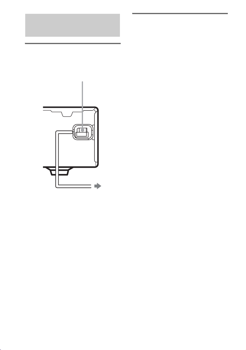
4: Connecting the AC power cord
Connecting the AC power
cord
Connect the AC power cord to a wall outlet.
AC power cord
Performing initial setup
operations
Before using the receiver for the first time,
initialize the receiver by performing the
following procedure.
This procedure can also be used to return
settings you have made to their factory defaults.
Use the buttons on the receiver for the operation.
1 Press ?/1 to turn off the receiver.
2 Hold down ?/1 for 5 seconds.
“INITIAL” appears in the display.
The following are reset to their factory
settings.
• All settings in the SET UP, LEVEL and
TONE menus.
• The sound field memorized for each
input and preset station.
• All sound field parameters.
• All preset stations.
• MASTER VOLUME is set to “VOL
MIN”.
14
To a wall outlet
GB
 Loading...