

Page 1
4-235-540-13(1)
Home Theater
System
Operating Instructions
Mode d’emploi
Manual de instrucciones
GB
FR
ES
HT-SL7
© 2001 Sony Corporation
Page 2

WARNING
To prevent fire or shock hazard, do not
expose the unit to rain or moisture.
To prevent fire, do not Cover the ventilation of the
apparatus with news papers, table-cloths, curtains,
etc. And don’t place lighted candles on the apparatus.
To prevent fire or shock hazard, do not place objects
filled with liquids, such as vases, on the apparatus.
Don’t throw away the battery with
general house waste, dispose of it
correctly as chemical waste.
Do not install the appliance in a confined space, such
as a bookcase or built-in cabinet.
CAUTION
TO PREVENT ELECTRIC SHOCK, DO NOT USE
THIS POLARIZED AC PLUG WITH AN
EXTENSION CORD, RECEPTACLE OR OTHER
OUTLET UNLESS THE BLADES CAN BE FULLY
INSERTED TO PREVENT BLADE EXPOSURE.
This receiver incorporates Dolby* Digital and Pro
Logic Surround and the DTS** Digital Surround
System.
* Manufactured under license from Dolby
Laboratories.
“Dolby”, “Pro Logic” and the double-D symbol are
trademarks of Dolby Laboratories.
**“DTS” and “DTS Digital Surround” are registered
trademarks of Digital Theater Systems, Inc.
Tip
The instructions in this manual describe the controls
on the receiver. You can also use the controls on the
supplied remote if they have the same or similar
names as those on the receiver. For details on the use
of your remote, see pages 33–36.
Demonstration Mode
The demonstration will activate the first time you
turn on the power. When the demonstration starts,
the following message appears in the display
twice:
“NOW DEMONSTRATION MODE IF YOU
FINISH DEMONSTRATION PLEASE PRESS
POWER KEY WHILE THIS MESSAGE
APPEARS IN THE DISPLAY THANK YOU”
To cancel the demonstration
Press ?/1 to turn the receiver off during the
previous message. The next time you turn the
receiver on, the demonstration will not appear.
To view the demonstration
Hold down SET UP and press ?/1 to turn on the
power.
Notes
• Running the demonstration will clear the
receiver’s memory. For details on what will be
cleared, see “Clearing the receiver’s memory”
on page 13.
• There will be no sound when the demonstration
mode is activated.
• You cannot cancel demonstration if you did not
press ?/1 while the above message is being
displayed. To cancel demonstration after the
above message appears, press ?/1 twice to
activate the demonstration again. Then, press
?/1 while the above message is being
displayed.
GB
2
Page 3

Table of Contents
Parts Identification
Main unit ...............................................4
Hooking Up the Components
Required cords....................................... 5
Antenna hookups ...................................6
Video component hookups ....................7
Digital component hookups................... 8
Multi channel input hookups .................9
Other hookups .....................................10
Hooking Up and Setting Up
the Speaker System
Speaker system hookups ..................... 11
Performing initial setup operations .....13
Multi channel surround setup .............. 13
Checking the connections.................... 18
Basic Operations
Selecting the component ..................... 18
Enjoying Surround Sound
Receiving Broadcasts
Manual memory .................................. 24
Automatic memory.............................. 24
Tuning to preset stations...................... 25
Automatic tuning .................................25
Direct tuning ........................................ 25
Other Operations
Using the Sleep Timer .........................26
Adjustments using the SET UP button...
Additional Information
Precautions ..........................................27
Troubleshooting................................... 27
Specifications ......................................29
Tables of settings using LEVEL/SURR
and SET UP buttons ...................... 31
Adjustable parameters for each sound
field ............................................... 32
Before you use your remote ................ 33
Remote button description................... 33
Changing the factory setting of
a function button ........................... 36
26
GB
Selecting a sound field ........................ 19
Understanding the multi channel
surround displays .......................... 21
Customizing sound fields .................... 22
GB
3
Page 4
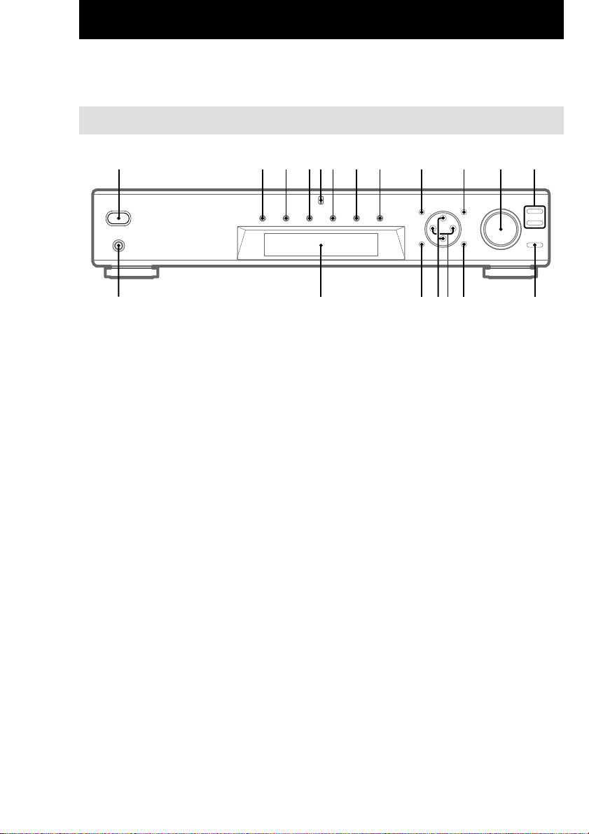
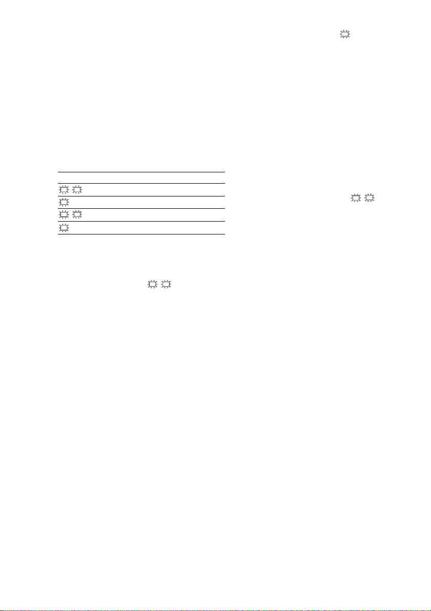
Parts Identification
The items are arranged in alphabetical order.
Refer to the pages indicated in parentheses ( ) for details.
Main unit
1 2 3 456 7 8 9 0 qa qs
ql
AUX 6 (18)
Cursor buttons (U/u) qh (14, 22–
26)
Display qk (21)
DVD 3 (18)
LEVEL/SURR qj (22, 23)
MASTER VOLUME qa (17, 18)
MEMORY/ENTER qf (24)
MULTI CH IN 8 (18)
MULTI CHANNEL DECODING
indicator 5
MUTING qd (18)
PHONES jack ql (18)
SET UP q; (14, 26)
SOUND FIELD +/– qs (19, 23)
TUNER 9 (25)
TUNER FM/AM 7 (18, 24, 25)
TV 4 (18)
VIDEO 2 (18)
?/1 (power) 1 (13, 17, 18, 23)
+/– qg (14, 22–26)
qk
qj qfqgqh
qd
GB
4
Page 5
Hooking Up the Components
Required cords
Before you get started
• Turn off the power to all components before making any connections.
• Do not connect the AC power cord until all of the connections are completed.
• Be sure to make connections firmly to avoid hum and noise.
• When connecting optical digital cords, take the caps off the connectors and insert the cord plugs straight
in until they click into place.
• Do not bend or tie the optical digital cord.
Hooking Up the Components
Parts Identification/Hooking Up the Components
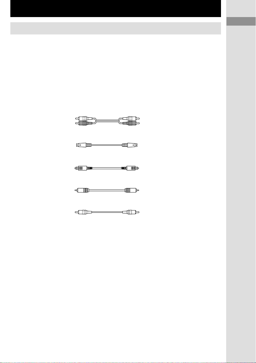
A Audio cord (not supplied)
B S-video cord (not supplied)
C Optical digital cord (not supplied)
D Coaxial digital cord (supplied)
E Monaural audio cord (not supplied)
White (L) White (L)
Red (R) Red (R)
Yellow (video) Yellow (video)
Black Black
Orange Orange
Black Black
GB
GB
5
5
Page 6
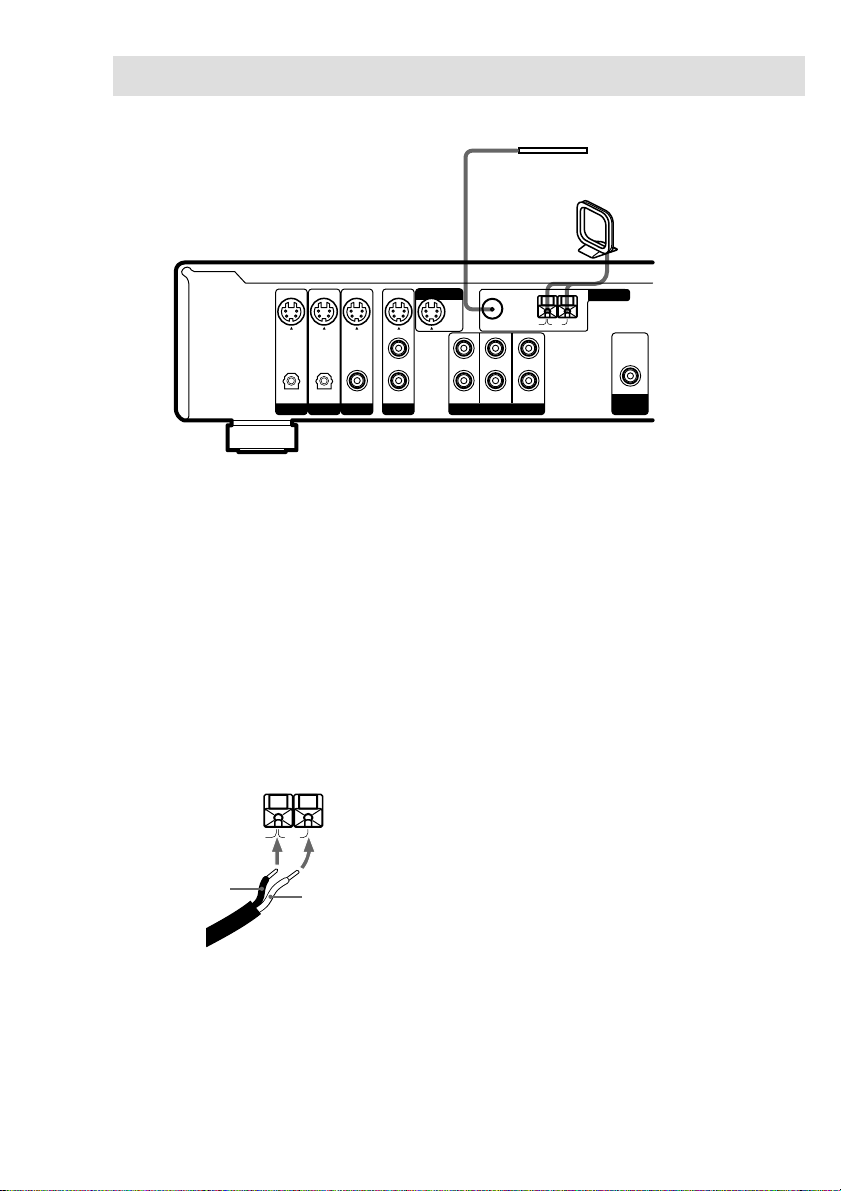
Antenna hookups
AM
B
A
U
S-VIDEO
DIGITAL
OPTICAL OPTICAL COAXIAL AUDIO IN
Notes on antenna hookups
• To prevent noise pickup, keep the AM loop
antenna away from the receiver and other
components.
• Be sure to fully extend the FM wire antenna.
• After connecting the FM wire antenna, keep it
as horizontal as possible.
• Do not use the U SIGNAL GND terminal for
grounding the receiver.
• When you connect the supplied AM loop
antenna, connect the black cord (B) to the U
terminal, and the white cord (A) to the other
terminal.
ININININ
L
R
VIDEO
DVDTVAUX
MONITOR OUT
FRONT
FM
75Ω COAXIAL
CENTER
SURROUND
SUB WOOFER
MULTI CH INPUT
FM wire antenna
(supplied)
AM loop antenna
(supplied)
ANTENNA
AM
U
OUT
SUB
WOOFER
GB
6
Page 7
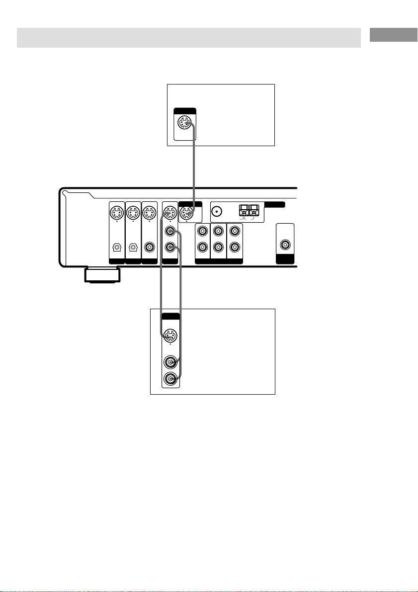
Video component hookups
For details on the required cords (A – E), see page 5.
INPUT
S-VIDEO
IN
B
Hooking Up the Components
TV monitor
S-VIDEO
DIGITAL
OPTICAL OPTICAL COAXIAL AUDIO IN
ININININ
L
R
VIDEO
DVDTVAUX
BA
OUTPUT
S-VIDEO
OUT
AUDIO
OUT
To apply sound effects to the
audio from the TV
You can connect your TV’s audio output jacks
to the VIDEO AUDIO IN jacks on the receiver
and apply sound effects to the audio from the
TV. In this case, do not connect the TV’s video
output jack to the VIDEO IN jack on the
receiver.
To switch the TV channels using the remote,
assign the VIDEO button to TV (page 36).
MONITOR OUT
FRONT
L
R
FM
75Ω COAXIAL
CENTER
SURROUND
SUB WOOFER
MULTI CH INPUT
VCR
ANTENNA
AM
U
OUT
SUB
WOOFER
GB
7
Page 8
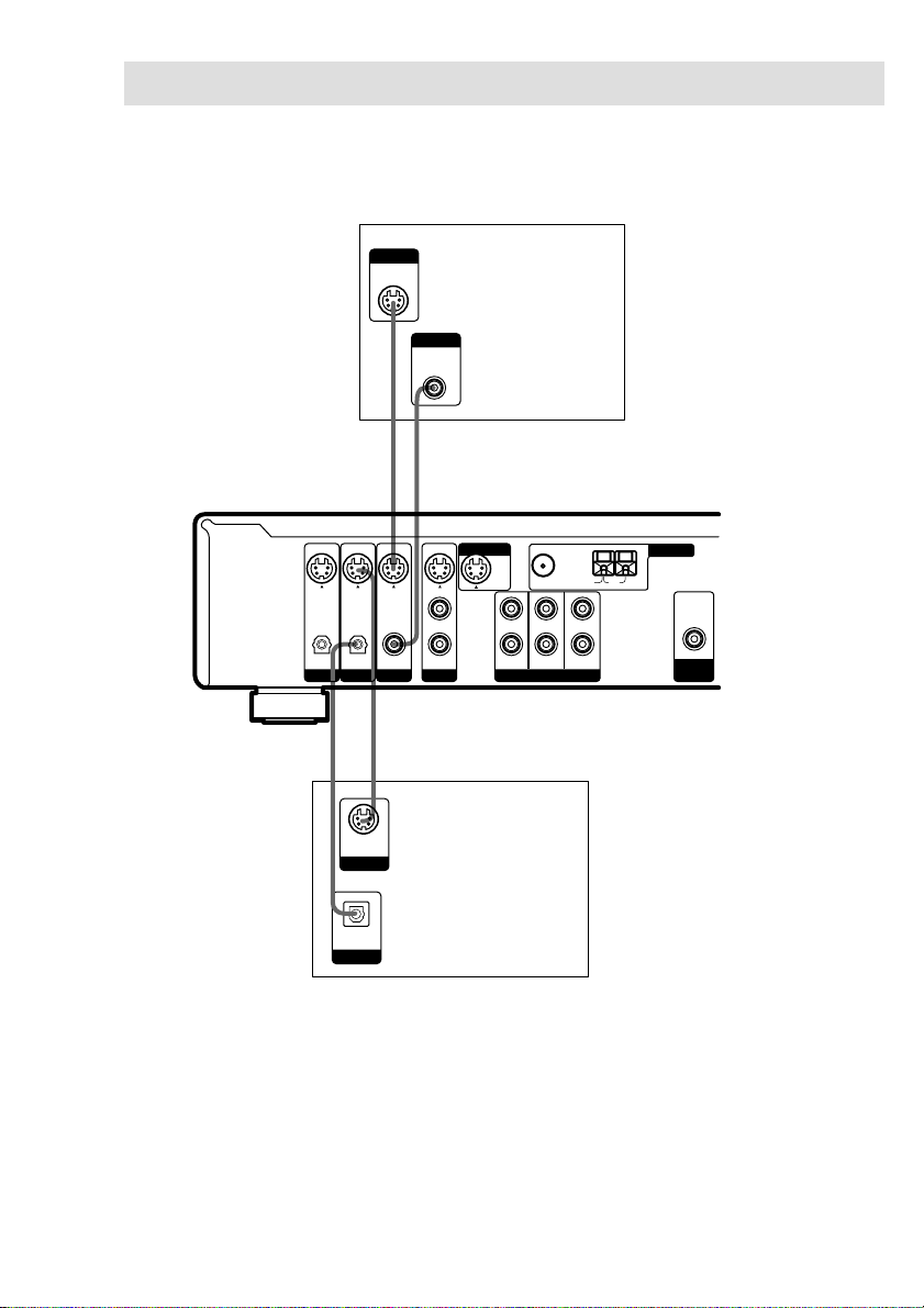
Digital component hookups
Connect the digital output jacks of your DVD player (etc.) to the receiver’s digital input jacks to
bring the multi channel surround sound of a movie theater into your home. To fully enjoy multi
channel surround sound, five speakers (two front speakers, two surround speakers, and a center
speaker) and a sub woofer are required.
OUTPUT
S-VIDEO
OUT
B
OUTPUT
DIGITAL
COAXIAL
D
DVD player
(etc.)
S-VIDEO
DIGITAL
OPTICAL OPTICAL COAXIAL AUDIO IN
C
S-VIDEO
OUT
OUTPUT
ININININ
MONITOR OUT
FM
75Ω COAXIAL
L
R
VIDEO
DVDTVAUX
FRONT
CENTER
SURROUND
SUB WOOFER
MULTI CH INPUT
B
Digital
ANTENNA
AM
U
OUT
SUB
WOOFER
satellite
tuner (etc.)
DIGITAL
OPTICAL
OUTPUT
Notes
• The OPTICAL input jacks are compatible with 48 kHz, 44.1 kHz and 32 kHz sampling frequencies.
• The COAXIAL input jack is compatible with 96 kHz, 48 kHz, 44.1 kHz and 32 kHz sampling frequencies.
GB
8
Page 9
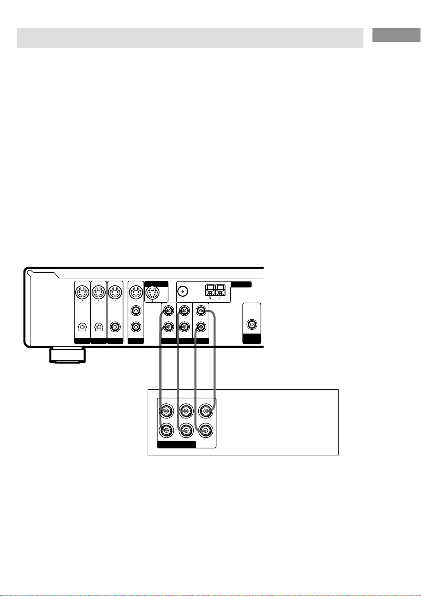
Multi channel input hookups
Although this receiver incorporates a multi channel decoder, it is also equipped with multi channel
input jacks. These connections allow you to enjoy multi channel software encoded in formats other
than Dolby Digital and DTS. If your DVD player is equipped with multi channel output jacks, you
can connect them directly to the receiver to enjoy the sound of the DVD player’s multi channel
decoder. Alternatively, the multi channel input jacks can be used to connect an external multi channel
decoder.
To fully enjoy multi channel surround sound, five speakers (two front speakers, two surround
speakers, and a center speaker) and a sub woofer are required. Refer to the operating instructions
supplied with your DVD player, multi channel decoder, etc., for details on the multi channel
hookups.
Tips
• To specify the video input to be used with the audio signals from the MULTI CH INPUT jacks, set the MULTI
CH IN visual input in the SET UP menu (page 26).
• You can use cord A instead of 2 cords E.
Notes
• When using the connections described below, adjust the level of the surround speakers and sub woofer from the
DVD player or multi channel decoder.
• See page 11 for details on speaker system hookup.
ININININ
S-VIDEO
DIGITAL
OPTICAL OPTICAL COAXIAL AUDIO IN
MONITOR OUT
FM
75Ω COAXIAL
L
R
VIDEO
DVDTVAUX
FRONT
CENTER
SURROUND
SUB WOOFER
MULTI CH INPUT
ANTENNA
AM
U
OUT
SUB
WOOFER
Hooking Up the Components
AAE E
FRONT
SURROUND
CENTER
L
R
SUB
MULTI CH OUT
WOOFER
DVD player,
Multichannel decoder, etc.
GB
9
Page 10
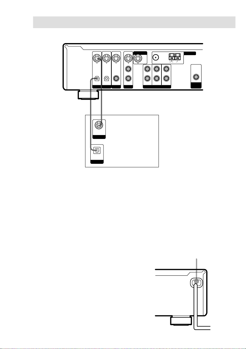
Other hookups
b
S-VIDEO
DIGITAL
OPTICAL OPTICAL COAXIAL AUDIO IN
BC
S-VIDEO
OUT
OUTPUT
DIGITAL
OPTICAL
OUTPUT
ININININ
L
R
VIDEO
DVDTVAUX
Audio/video
component
MONITOR OUT
FRONT
FM
75Ω COAXIAL
CENTER
SURROUND
SUB WOOFER
MULTI CH INPUT
ANTENNA
AM
U
OUT
SUB
WOOFER
10
AUX hookups
If you have an individual audio/video
component
Use an optical digital cord (not supplied) to
connect the optical output jack on the CD
player, MD deck, or video game player to the
AUX OPTICAL jack on the receiver so that
you can listen to stereo sources in surround
sound.
Use the S-video cable (not supplied) to connect
the S-video output jack on your video
component to the AUX S-VIDEO IN jack on
the receiver.
GB
Connecting the AC power
cord
Before connecting the AC power cord of this
receiver to a wall outlet, connect the speaker
system to the receiver (see page 11).
Connect the AC power cord(s) of your audio/
video components to a wall outlet.
Note
If the AC power cord is disconnected for about two
weeks, the receiver’s entire memory will be cleared
and the demonstration will start.
AC power cord
To a wall outlet
Page 11
Hooking Up and Setting Up the Speaker System
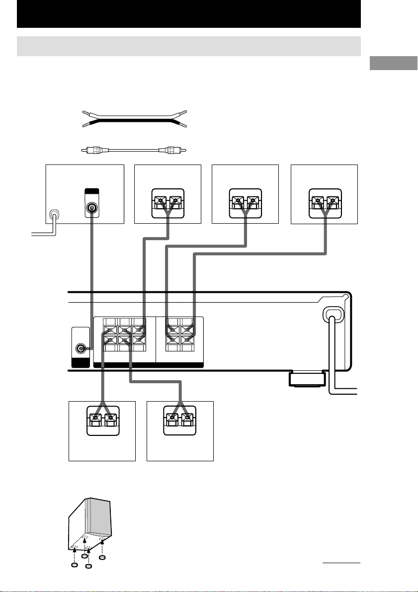
Speaker system hookups
Before connecting speakers, be sure to turn off this unit.
Required cords
A Speaker cords (supplied)
(+) (+)
(–) (–)
B Monaural audio cord (supplied)
Black Black
Active sub woofer
b
To a wall outlet
(Switch the power
(POWER) to off
before connecting the
power cord.)
WOOFER
OUT
SUB
INPUT
AUDIO
IN
B
+
–
RL RL
SURROUND
Center speaker
+–+
–
CENTER
SPEAKERS
FRONT
(IMPEDANCE USE 8–16Ω)
+
–
Front speaker (R)
Ee Ee
AA
Front speaker (L)
E
A
Hooking Up and Setting Up the Speaker System
e
A
E
Surround speaker
(R)
Tip
E
e
Surround speaker
To prevent speaker vibration or movement while
listening, attach the supplied foot pads at the bottom
of the speakers.
(L)
A
e
continued
11
GB
Page 12
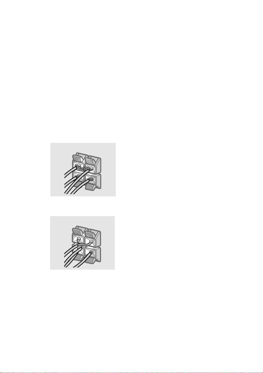
Speaker system hookups (continued)
To avoid short-circuiting the
speakers
Short-circuiting of the speakers may damage
the receiver. To prevent this, make sure to take
the following precautions when connecting the
speakers.
Make sure the stripped ends of each
speaker cord does not touch another
speaker terminal, the stripped end of
another speaker cord, or the metal parts of
the receiver.
Examples of poor conditions of the
speaker cord
Stripped speaker cord is touching another
speaker terminal.
After connecting all the components,
speakers, and AC power cord, output
a test tone to check that all the
speakers are connected correctly.
For details on outputting a test tone,
see page 17.
If no sound is heard from a speaker while
outputting a test tone or a test tone is output
from a speaker other than the one whose name
is currently displayed on the receiver, the
speaker may be short-circuited. If this happens,
check the speaker connection again.
To avoid damaging your
speakers
Make sure that you turn down the volume
before you turn off the receiver. When you turn
on the receiver, the volume remains at the level
you turn off the receiver.
12
Stripped cords are touching each other
due to excessive removal of insulation.
GB
Page 13
Performing initial setup
Multi channel surround
operations
Once you have hooked up the speakers and
turned on the power, clear the receiver’s
memory. Then specify the speaker parameters
(size, position, etc.) and perform any other
initial setup operations necessary for your
system.
Tip
To check the audio output during settings (to set up
while outputting the sound), check the connection
(see page 18).
Clearing the receiver’s
memory
Before using your receiver for the first time, or
when you want to clear the receiver’s memory,
do the following.
This procedure is not necessary if the
demonstration activates when you turn on the
power.
1 Turn off the receiver.
2 Hold down ?/1 for 5 seconds.
The demonstration starts (see page 2) and
all of the following items are reset or
cleared:
• All sound field parameters are reset to
their factory settings.
• All SET UP parameters are reset to
their factory settings.
• The sound fields memorized for each
program source and preset stations are
cleared.
• The master volume is set to “MIN”.
Performing initial setup operations
Before using your receiver for the first time,
adjust SET UP parameters so that the receiver
correspond to your system. For the adjustable
parameters, see the table on page 31. See pages
13–17 for speaker settings and page 26 for
other settings.
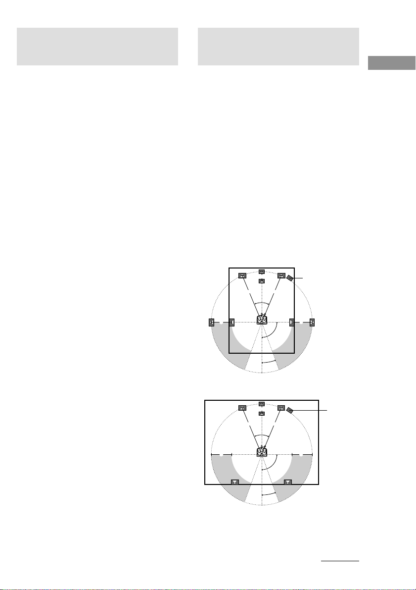
setup
For the best possible surround sound, all
speakers should be the same distance from the
listening position (A).
However, the receiver lets you to place the
center speaker up to 1.5 meters closer (B) and
the surround speakers up to 4.5 meters closer
(C) to the listening position.
The front speakers can be placed from 1.0 to
12.0 meters from the listening position (A).
You can place the surround speakers either
behind you or to the side, depending on the
shape of your room (etc.).
Place the sub woofer at the same distance from
the listening position as the front speaker (left
or right).
When placing surround speakers to your side
B
AA
45°
90°
20°
When placing surround speakers behind you
B
AA
45°
90°
20°
Note
Do not place the center speaker farther away from the
listening position than the front speakers.
Sub woofer
CC
Sub woofer
CC
continued
Hooking Up and Setting Up the Speaker System
GB
13
Page 14

Multi channel surround setup
(continued)
Specifying the speaker
parameters
1 Press SET UP.
2 Press the cursor buttons (U or u) to
select the parameter you want to
adjust.
3 Press + or – to select the setting you
want.
The setting is stored automatically.
4 Repeat steps 2 to 3 until you have set
all of the parameters that follow.
Initial settings
Parameter Initial setting
L
R (FRONT) XX.X m DIST. 5.0 m
C
(CENTER) XX.X m DIST. 5.0 m
SL
SR (SURR) XX.X m DIST. 3.5 m
SL
SR (SURR) PL. XXX PL. BEHD.
SL
SR (SURR) HGT. XXX HGT. LOW
x Front speaker distance (L R)
Set the distance from your listening position to
the front speakers (A on page 13).
x Center speaker distance (C)
Set the distance from your listening position to
the center speaker. Center speaker distance
should be set from a distance equal to the front
speaker distance (A on page 13) to a distance
1.5 meters closer to your listening position (B
on page 13).
x Surround speaker distance (SL SR)
Set the distance from your listening position to
the surround speakers. Surround speaker
distance should be set from a distance equal to
the front speaker distance (A on page 13) to a
distance 4.5 meters closer to your listening
position (C on page 13).
Tip
The receiver allows you to input the speaker position
in terms of distance. However, it is not possible to set
the center speaker further than the front speakers.
Also, the center speaker cannot be set more than
1.5 meters closer than the front speakers.
Likewise, the surround speakers can not be set farther
away from the listening position than the front
speakers. And they can be no more than 4.5 meters
closer.
This is because incorrect speaker placement is not
conducive to the enjoyment of surround sound.
Please note that, setting the speaker distance closer
than the actual location of the speakers will cause a
delay in the output of the sound from that speaker. In
other words, the speaker will sound like it is farther
away.
For example, setting the center speaker distance
1~2 m closer than the actual speaker position will
create a fairly realistic sensation of being “inside” the
screen. If you cannot obtain a satisfactory surround
effect because the surround speakers are too close,
setting the surround speaker distance closer (shorter)
than the actual distance will create a larger sound
stage.
Adjusting these parameter while listening to the
sound often results in much better surround sound.
Give it a try!
14
GB
Page 15
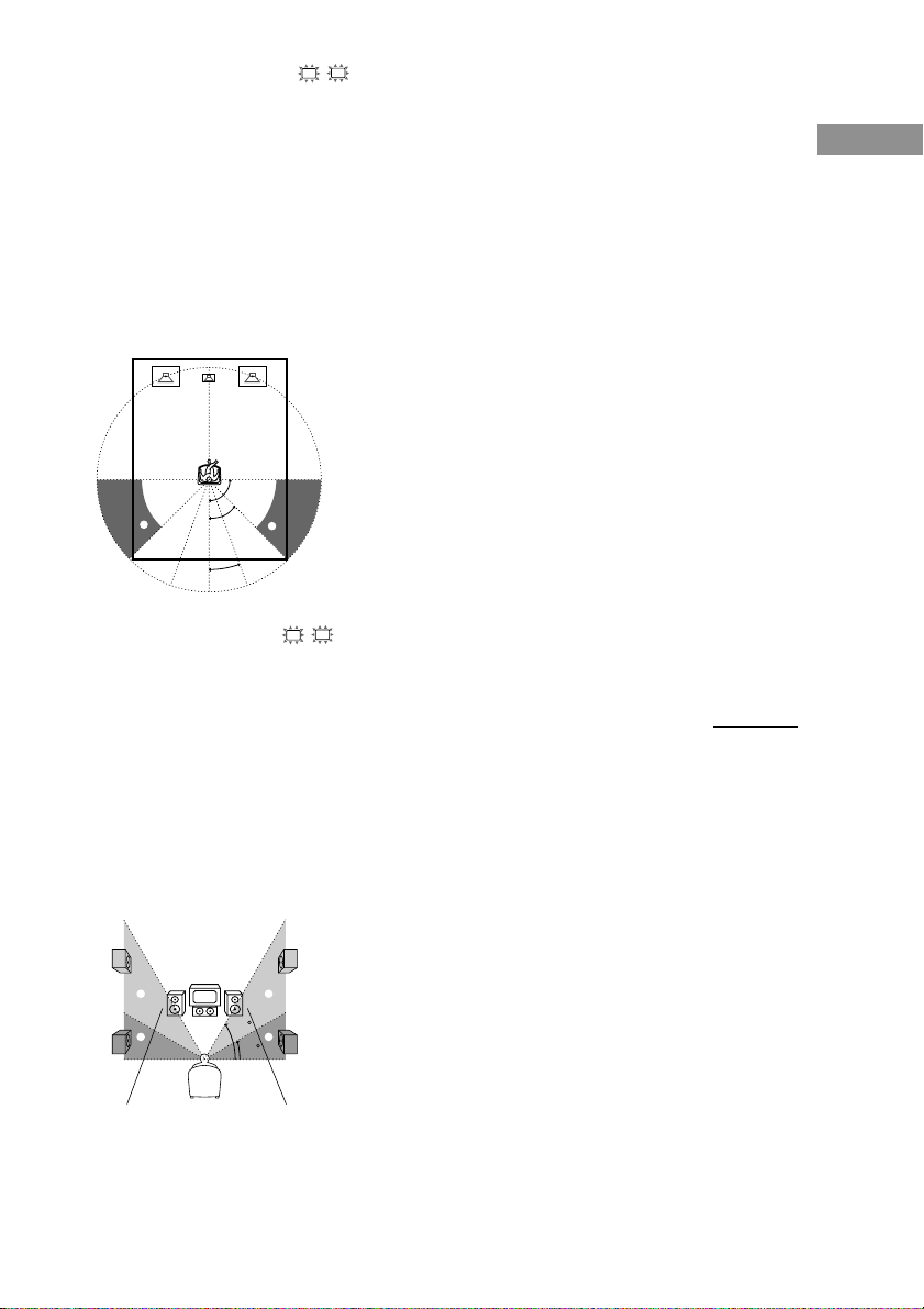
x Surround speaker position (SL SR)*
This parameter lets you specify the location of
your surround speakers for proper
implementation of the Digital Cinema Sound
surround modes in the “VIRTUAL” sound
fields. Refer to the illustration below.
• Select “PL. SIDE” if the location of your
surround speakers corresponds to section A.
• Select “PL. BEHD.” if the location of your
surround speakers corresponds to section B.
This setting only effects the surround modes in
the “VIRTUAL” sound fields.
90°
A
B
A
45°
B
20°
x Surround speaker height (SL SR)*
This parameter lets you specify the height of
your surround speakers for proper
implementation of the Digital Cinema Sound
surround modes in the “VIRTUAL” sound
fields. Refer to the illustration below.
• Select “HGT. LOW” if the location of your
surround speakers corresponds to section A.
• Select “HGT. HIGH” if the location of your
surround speakers corresponds to section B.
This setting only effects the surround modes in
the “VIRTUAL” sound fields.
Tip
The surround speaker position parameter is designed
specifically for implementation of the Digital Cinema
Sound modes in the “VIRTUAL” sound fields.
With the Digital Cinema Sound modes, speaker
position is not as critical as other modes. All of the
modes in the “VIRTUAL” sound fields were
designed under the premise that the surround speaker
would be located behind the listening position, but
presentation remains fairly consistent even with the
surround speakers positioned at a rather wide angle.
However, if the speakers are pointing toward the
listener from the immediate left and right of the
listening position, the “VIRTUAL” sound fields will
not be effective unless the surround speaker position
parameter is set to “PL. SIDE”.
Nevertheless, each listening environment has many
variables, like wall reflections, and you may obtain
better results using “PL. BEHD.” if your speakers are
located high above the listening position, even if they
are to the immediate left and right.
Therefore, although it may result in a setting contrary
to the “Surround speaker position” explanation, we
recommend that you playback multi channel surround
encoded software and listen to the effect each setting
has on your listening environment. Choose the setting
that provides a good sense of spaciousness and that
best succeeds in forming a cohesive space between
the surround sound from the surround speakers and
the sound of the front speakers. If you are not sure
which sounds best, select “PL. BEHD.” and then use
the speaker distance parameter and speaker level
adjustments to obtain proper balance.
continued
Hooking Up and Setting Up the Speaker System
B
A
B
60
A
30
* These parameters are not available when
“Surround speaker size” is set to “NO”.
15
GB
Page 16
Multi channel surround setup
(continued)
Only when you use the speaker system
other than the supplied one, be sure to
set the following parameters.
The speaker size and sub woofer selection has been
preset to MICRO SP. (Micro Satellite Speaker)
according to the supplied speaker system. If you
change the speaker system, choose NORM. SP.
(Normal Speaker) to adjust the speaker size and sub
woofer selection. To select NORM. SP., turn off the
power, then turn on again while pressing the cursor
button U. (To reset to MICRO SP., do the same
procedure.)
Parameter Initial setting
L
R (FRONT) LARGE
C
(CENTER) LARGE
SL
SR (SURR) LARGE
SW
(SUB WOOFER) S.W. YES
You cannot change the configuration if you choose
MICRO SP.
x Front speaker size (L R)
• If you connect large speakers that will
effectively reproduce bass frequencies, select
“LARGE”.
• If the sound is distorted, or you feel a lack of
surround effects when using multi channel
surround sound, select “SMALL” to activate
the bass redirection circuitry and output the
front channel bass frequencies from the sub
woofer.
• When the front speakers are set to “SMALL”,
the center and surround speakers are also
automatically set to “SMALL” (unless
previously set to “NO”).
x Center speaker size (C)
• If you connect a large speaker that will
effectively reproduce bass frequencies, select
“LARGE”. However, if the front speakers are
set to “SMALL”, you cannot set the center
speaker to “LARGE”.
• If the sound is distorted, or you feel a lack of
surround effects when using multi channel
surround sound, select “SMALL” to activate
the bass redirection circuitry and output the
center channel bass frequencies from the front
speakers (if set to “LARGE”) or sub woofer.*
• If you do not connect a center speaker, select
“NO”. The sound of the center channel will be
output from the front speakers.*
2
x Surround speaker size (SL SR)
• If you connect large speakers that will
effectively reproduce bass frequencies, select
“LARGE”. However, if the front speakers are
set to “SMALL”, you cannot set the surround
speakers to “LARGE”.
• If the sound is distorted, or you feel a lack of
surround effects when using multi channel
surround sound, select “SMALL” to activate
the bass redirection circuitry and output the
surround channel bass frequencies from the sub
woofer or other “LARGE” speakers.
• If you do not connect surround speakers, select
Tip
*1–*3 correspond to the following Dolby Pro Logic
modes
*1 NORMAL
*2 PHANTOM
*3 3 STEREO
“NO”.*
3
1
16
GB
Page 17
Tip
Internally, the LARGE and SMALL settings for each
speaker determine whether or not the internal sound
processor will cut the bass signal from that channel.
When the bass is cut from a channel, the bass
redirection circuitry sends the corresponding bass
frequencies to the sub woofer or other “LARGE”
speakers.
However, since bass sounds have a certain amount of
directionality, it best not to cut them, if possible.
Therefore, even when using small speakers, you can
set them to “LARGE” if you want to output the bass
frequencies from that speaker. On the other hand, if
you are using a large speaker, but prefer not to have
bass frequencies output from that speaker, set it to
“SMALL”.
If the overall sound level is lower than you prefer, set
all speakers to “LARGE”.
x Sub woofer selection (SW)
•
If you connect a sub woofer, select “S.W. YES”.
• If you do not connect a sub woofer, select
“S.W. NO”. This activates the bass redirection
circuitry and outputs the LFE signals from other
speakers.
• In order to take full advantage of the Dolby
Digital bass redirection circuitry, we
recommend setting the sub woofer’s cut off
frequency as high as possible.
Adjusting the speaker level
Use the remote while seated in your listening
position to adjust the level of each speaker.
Note
The receiver incorporates a new test tone with a
frequency centered at 800 Hz for easier speaker level
adjustment.
5 Press TEST TONE on the remote.
You will hear the test tone from each
speaker in sequence.
Front (left) t Center t Front (right) t
Surround (right) t Surround (left) t
Sub woofer
6 Adjust the level parameters so that the
level of the test tone from each speaker
sounds the same when you are in your
main listening position.
To adjust the balance and level of speakers,
press MENU < / > on the remote to select the
level parameter you want to adjust (page 22).
Then press MENU +/– to select the setting.
7 Press TEST TONE again to turn off the
test tone.
Tip
You can adjust the level of all speakers at the same
time. Turn MASTER VOLUME on the main unit or
press MASTER VOL +/– on the remote.
Notes
• The test tone is not output when the MULTI CH IN
function is on.
• The front balance, surround balance, center level,
surround level, and sub woofer level are shown in
the display during adjustment.
•
Although these adjustments can also be made via the
front panel using the LEVEL menu (when the test tone
is output, the receiver switches to the LEVEL menu
automatically), we recommend you follow the
procedure described above and adjust the speaker
levels from your listening position using the remote.
• To enjoy the better sound quality, do not turn the
volume of the subwoofer too high.
continued
Hooking Up and Setting Up the Speaker System
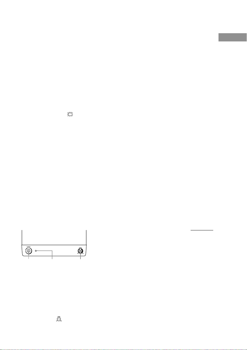
POWER LEVEL
POWER indicator
1 Press ?/1 to turn on the receiver.
2 Turn MASTER VOLUME on the receiver
clockwise (until 10 to 20 appears in the
display).
3 Turn on the power of the sub woofer.
4 Turn LEVEL on the sub woofer
clockwise (about position).
17
GB
Page 18

Multi channel surround setup
(continued)
Tip
In addition to outputting the test tone, you can also
adjust the level of each speaker while listening to the
sound of a CD or DVD, etc. Although you lay the
foundation for high quality surround sound by
matching the levels of all speakers using the test tone,
it may be necessary to make further adjustments
while listening to playback of actual software. This is
because most software contains center and surround
channels recorded at slightly lower levels than the
two front channels.
When you actually playback software recorded in
multi channel surround you will notice that increasing
the center and surround speaker levels produces a
better blend between the front and center speakers
and greater cohesion between the front and surround
speakers. Increasing the level of the center speaker
about 1 dB, and the surround speakers about 1~2 dB
is likely to produce better results.
In other words, in order to create a more cohesive
soundstage with balanced dialog we recommend that
you make some adjustments while playing your
software. Changes of only 1 dB can make a huge
difference in the character of the soundstage.
Checking the connections
After connecting all of your components to the
receiver, do the following to verify that the
connections were made correctly.
1 Press ?/1 to turn on the receiver.
2 Press a function button to select a
component (program source) that you
connected (e.g., DVD player).
3 Turn on the component and start
playing it.
4 Rotate MASTER VOLUME to turn up the
volume.
If you do not obtain normal sound output after
performing this procedure, see
“Troubleshooting” on page 27 and take the
appropriate measures to correct the problem.
Basic Operations
Selecting the component
Function buttons
Press a function button to select the component
you want to use.
To select Press
VCR VIDEO
DVD player DVD
Digital satellite tuner (etc.) TV
Tuner TUNER FM/AM
An audio/video AUX
component
After turning on the component you selected,
select the component and play the program
source.
MULTI CH IN
Press MULTI CH IN to enjoy the audio source
connected to the MULTI CH INPUT jacks with
the video from the selected component.
• When the MULTI CH IN is selected, the sound
field and surround parameters do not function.
MUTING
Press MUTING to mute the sound. MUTING
appears on the display when the sound is
muted. The muting function is canceled when
turning the power off, or disconnecting the
power cord.
PHONES
Use the PHONES jack to connect headphones.
• When the headphones are connected, speaker
output is automatically cancelled.
18
GB
Page 19

Enjoying Surround Sound
You can take advantage of surround sound
simply by selecting one of the receiver’s preprogrammed sound fields. They bring the
exciting and powerful sound of movie theaters
and concert halls into your home. You can also
customize the sound fields to obtain the sound
you want by changing the various surround
parameters.
To fully enjoy surround sound, you must
register the number and location of you
speakers. See “Multi channel surround setup”
starting from page 13 to set the speaker
parameters before enjoying surround sound.
Selecting a sound field
You can enjoy surround sound simply by
selecting one of the pre-programmed sound
fields according to the program you want to
listen to.
Press SOUND FIELD +/– repeatedly to
select the sound field you want.
The current sound field is indicated in the
display. See pages 19–20 for information on
each sound field.
To turn the surround effect off
Select A.F.D. or 2CH ST. (page 20).
Tips
• The receiver memorizes the last sound field selected
for each program source (Sound Field Link).
Whenever you select a program source, the sound
field that was last applied is automatically applied
again. For example, if you listen to DVD with
HALL as the sound field, change to a different
program source, then return to DVD, HALL will be
applied again.
• You can identify the encoding format of program
software by looking at its packaging.
Dolby Digital discs are labeled with the
logo, and Dolby Surround encoded programs are
labeled with the logo.
About DCS (Digital Cinema Sound)
DCS is the concept name of the surround
technology for home theater developed by
Sony. DCS uses the DSP (Digital Signal
Processor) technology to reproduce the sound
characteristics of an actual cinema cutting
studio in Hollywood.
When played at home, DCS will create a
powerful theater effect that mimics the artistic
combination of sound and action as envisioned
by the movie director.
x NORM.SURR. (Normal Surround)
Software with multi channel surround audio
signals is played back according to the way it
was recorded. Software with 2 channel audio
signals is decoded with Dolby Pro Logic to
create surround effects.
x STUDIO A–C (Cinema Studio A–C)
DCS
• CINEMA STUDIO A reproduces the sound
characteristics of Sony Pictures Entertainment’s
classic editing studio.
• CINEMA STUDIO B reproduces the sound
characteristics of Sony Pictures Entertainment’s
mixing studio which is one of the most up-todate facilities in Hollywood.
• CINEMA STUDIO C reproduces the sound
characteristics of Sony Pictures Entertainment’s
BGM recording studio.
continued
Basic Operations/Enjoying Surround Sound
Enjoying Surround Sound
19
GB
Page 20

Selecting a sound field (continued)
x V.M.DIMENS.* (Virtual Multi Dimension)
DCS
Uses 3D sound imaging to create an array of
virtual surround speakers positioned higher
than the listener from a single pair of actual
surround speakers. This mode creates 4 sets of
virtual speakers surrounding the listener at
approximately a 30° angle of elevation.
x V.SEMI M.D.* (Virtual Semi Multi
Dimension) DCS
Uses 3D sound imaging to create virtual
surround speakers from the sound of the front
speakers without using actual surround
speakers. This mode creates 5 sets of virtual
speakers surrounding the listener at a 30° angle
of elevation.
x HALL
Reproduces the acoustics of a rectangular
concert hall.
x JAZZ (Jazz Club)
Reproduces the acoustics of a jazz club.
x L.HOUSE (Live House)
Reproduces the acoustics of a 300-seat live
house.
x GAME
Obtains maximum audio impact from video
game software.
Use the buttons on the remote to operate the
following modes.
A.F.D. (AUTO FORMAT DECODING)
Automatically detects the type of audio signal
being input (Dolby Digital, DTS, or standard 2
channel stereo) and performs the proper
decoding if necessary. This mode presents the
sound as it was recorded/encoded, without
adding any effects (ex. reverberation).
2CH ST. (2 CHANNEL)
Outputs the sound from the front left and right
speakers only. Standard 2 channel (stereo)
sources completely bypass the sound field
processing. Multi channel surround formats are
downmixed to 2 channel.
Notes
• No sound is output from the sub woofer when
you select NORM. SP. (page 16) and “2CH ST.” is
selected. To listen to 2 channel (stereo) sources
using the front left and right speakers and a sub
woofer, select “A.F.D.”.
• When you select MICRO SP., internal sound
processor will automatically redirect bass sound to
subwoofer.
20
* “VIRTUAL” sound field: Sound field with virtual
speakers.
Notes
• The effects provided by the virtual speakers may
cause increased noise in the playback signal.
• When listening with sound fields that employ the
virtual speakers, you will not be able to hear any
sound coming directly from the surround speakers.
GB
Page 21

L F E
Understanding the multi channel surround displays
1q; qa 2 3 4
9
SLEEP
SW
L C R
L F E
S SR
SL
8
a
OPTSP. OFF
DIGITAL
PRO LOGIC
COAX
1 ; DIGITAL: Lights up when the receiver is
decoding signals recorded in the Dolby
Digital format.
2 PRO LOGIC: Lights up when the receiver
applies Pro Logic processing to 2 channel
signals in order to output the center and
surround channel signals. However, this
indicator does not light if the center and
surround speakers are set to “NO”, and
“A.F.D.” or “NORMAL SURROUND” is
selected.
3 DTS: Lights up when DTS signals are input.
4 Tuner indicators: Light up when using the
receiver to tune in radio stations, etc. See
pages 24–25 for tuner operations.
5 D.RANGE: Lights up when dynamic range
compression is activated. See page 23 to
adjust the dynamic range compression.
6 COAX: Lights up when the source signal is a
digital signal being input through the
COAXIAL terminal.
7 OPT: Lights up when the source signal is a
digital signal being input through the
OPTICAL terminal.
DTS
D.RANGE
STEREO/MONO MEMORY
567
8 Playback channel indicators: The letters
light up to indicate the channels being played
back.
L (Front Left), R (Front Right), C (Center
(monaural)), SL (Surround Left), SR
(Surround Right), S (Surround (monaural or
the surround components obtained by Pro
Logic processing)), SW (Sub woofer)
The boxes around the letters light up to
indicate the speakers used to playback the
channels.
9
: Lights up when the disc being
played back contains the LFE (Low
Frequency Effect) channel and when the
sound of the LFE channel signal is actually
being reproduced.
0 SLEEP: Lights up when sleep timer is
activated.
qa SP.OFF: Lights up when headphones are
inserted.
Enjoying Surround Sound
21
GB
Page 22

Customizing sound fields
By adjusting the surround and level parameters
of the front, center, and surround speakers, you
can customize the sound fields to suit your
particular listening situation.
Once you customize a sound field, the changes
are stored in the memory indefinitely (unless
the receiver is unplugged for about two weeks).
You can change a customized sound field any
time by making new adjustments to the
parameters.
See the tables on page 32 for the parameters
available in each sound field.
To get the most from multi
channel surround sound
Position your speakers and do the procedures
described in “Multi channel surround setup”
starting from page 13 before you customize a
sound field.
Adjusting the level
parameters
The LEVEL menu contains parameters that let
you adjust the balance and volumes of each
speaker. The settings are applied to all sound
fields.
1 Start playing a program source
encoded with multi channel surround
sound.
2 Press LEVEL/SURR.
The button lights up and the first parameter
is displayed.
3 Press the cursor buttons (U or u) to
select the parameter you want to
adjust.
4 Press + or – to select the setting you
want.
The setting is stored automatically.
Initial settings
Parameter Initial setting
FRONT BALANCE* BALANCE
SURR BALANCE* BALANCE
CENTER LEVEL* CTR 0 dB
SURR LEVEL* SURR 0 dB
SUB WOOFER LEVEL* S.W. 0 dB
LFE MIX LEVEL L.F.E. 0 dB
DYNAMIC RANGE COMP COMP. OFF
* These parameters can be adjusted separately for
MULTI CH IN.
Front balance (L R)
Lets you adjust the balance between front left
and right speakers.
Surround balance (SL SR)
Lets you adjust the balance between surround
left and right speakers.
Center level (C)
Lets you adjust the level of the center speaker.
Surround level (SL SR)
Lets you adjust the level of the surround left
and right speakers.
Sub woofer level (SW)
Lets you adjust the level of the sub woofer.
Low Frequency Effect (
Lets you attenuate the level of the LFE (Low
Frequency Effect) channel output from the sub
woofer without effecting the level of the bass
frequencies sent to the sub woofer from the
front, center or surround channels via the
Dolby Digital or DTS bass redirection
circuitry.
•“0 dB” outputs the full LFE signal at the mix
level determined by the recording engineer.
• To mute the sound of the LFE channel from the
sub woofer, select “OFF”. However, the low
frequency sounds of the front, center, or
surround speakers are output from the sub
woofer according to the settings made for each
speaker in the speaker setup (pages 16–17).
LFE
)
22
GB
Page 23

Dynamic range compressor (
Lets you compress the dynamic range of the
sound track. This may be useful when you want
to watch movies at low volumes late at night.
We recommend using the “MAX” setting.
• To reproduce the sound track with no
compression, select “COMP. OFF”.
• To reproduce the sound track with the dynamic
range intended by the recording engineer, select
“COMP. STD”.
• To compress the dynamic range in small steps
to achieve the sound you desire, select “COMP.
0.1”–“COMP. 0.9”.
• To reproduce a dramatic compression of the
dynamic range, select “COMP. MAX”.
Note
Dynamic range compression is possible with Dolby
Digital sources only.
D. RANGE
Adjusting the surround
parameters
The SURR menu contains parameters that let
you customize various aspects of the current
sound field. The settings are stored individually
for each sound field.
1 Start playing a program source
encoded with multi channel surround
sound.
2 Press LEVEL/SURR.
The button lights up and the first parameter
is displayed.
3 Press the cursor buttons (U or u) to
select the parameter you want to
adjust.
4 Press + or – to select the setting you
want.
The setting is stored automatically.
)
Initial settings
Parameter Initial setting
EFFECT LEVEL (depends on the sound field)
WALL TYPE WALL MID
REVERBERATION REVB. MID
TIME
Effect level (EFFECT)
Lets you adjust the “presence” of the current
surround effect.
Wall type (WALL)
Lets you control the level of the high
frequencies to alter the sonic character of your
listening environment by simulating a softer (S)
or harder (H) wall. The midpoint designates a
neutral wall (made of wood).
Reverberation (REVERB)
Lets you control the spacing of the early
reflections to simulate a sonically longer (L) or
shorter (S) room. The midpoint designates a
standard room with no adjustment.
Resetting customized sound
fields to the factory settings
1 If the power is on, press ?/1 to turn off
the power.
2 Hold down SOUND FIELD + and press
?/1.
“S.F. CLR.” appears in the display and all
sound fields are reset at once.
Enjoying Surround Sound
23
GB
Page 24

Receiving Broadcasts
Before receiving broadcasts, make sure you
have connected FM and AM antennas to the
receiver (see page 6).
Manual memory
You can enter a frequency of the station you
want directly by using the cursor buttons, and
preset the stations to the receiver.
1 Press TUNER FM/AM to select the FM
or AM band.
2 Press MEMORY/ENTER.
The receiver enters the Manual Memory
mode.
The current frequency appears and the
preset number flashes in the display.
Do steps 3 to 5 before “PUSH” and
“ENTER” flashes in the display.
3 Press +/– to tune in a station.
If “PUSH” and “ENTER” flashes before
you tune in a station, start again from step 2.
4 Press the cursor buttons (U or u) to
select a preset number.
If “PUSH” and “ENTER” flashes before
you select the preset number, start again
from step 2.
5 Press MEMORY/ENTER.
6 Repeat steps 2 to 5 to preset another
station.
Tip
When the FM station is tuned in, you can press
TUNER to switch the MONO mode to STEREO
mode manually.
Automatic memory
If you don’t know the frequency of the station
you want, you can let the receiver scan all
available stations in your area and preset the
stations to the receiver.
Press and hold MEMORY/ENTER, then
press ?/1.
“AUTO MEMORY START” appears in the
display.
The receiver scans from low to high
frequencies of FM stations, then repeat
scanning of AM stations.
When a station is tuned in, the station is
automatically stored in the memory in the
following order.
tA1tA2t...tA0tB1tB2t...tB0
C0T...C2TC1T
If all preset channels are memorized before
scanning all stations, scanning stops and
“MEM. FULL” appears in the display.
To cancel
Press ?/1 during any step.
24
GB
Page 25

Tuning to preset stations
Automatic tuning
After preseting radio stations, you can tune in
any of them directly by entering its
2-character preset code using the supplied
remote. Up to 30 FM or AM stations can be
preset. The receiver will also scan all the
stations that you have preset.
You can tune the preset stations by either of the
following two ways.
Scanning the preset stations
1 Press TUNER.
2 Press the cursor buttons (U or u)
repeatedly to select the preset station
you want.
Each time you press the button, the receiver
tunes in one preset station at a time, in the
corresponding order and direction as
follows:
tA1yA2y...yA0yB1yB2y...yB0T
tC0y...C2yC1T
Using the preset codes
Use the supplied remote to perform the
following operations. For details on the buttons
used in this section, see pages 33–34.
1 Press TUNER.
The last received station is tuned in.
2 Press SHIFT to select a memory page
(A, B, or C), then press the preset
number of the station you want using
the numeric buttons.
If you don’t know the frequency of the station
you want, you can let the receiver scan all
available stations in your area.
1 Press TUNER FM/AM to select the FM
or AM band.
The last received station is tuned in.
2 Press + or –.
Press + to scan from low to high; press – to
scan from high to low.
The receiver stops scanning whenever a
station is received.
When the receiver reaches either end of
the band
Scanning is repeated in the same direction.
3 To continue scanning, press + or –
again.
Tips
• If you press + or – during Automatic Tuning,
Automatic Tuning stops.
• If you press + or – within a second after the
Automatic Tuning stops, the frequency changes by
a single step.
Direct tuning
You can enter a frequency of the station you
want directly by using the numeric buttons on
the supplied remote.
1 Press TUNER on the remote.
2 Press FM/AM to select the FM or AM
band.
3 Press D.TUNING.
4 Press the numeric buttons to enter the
frequency.
Receiving Broadcasts
If you cannot tune in a station and
the entered numbers flash
Make sure you’ve entered the right frequency.
If not, repeat steps 3 and 4. If the entered
numbers still flash, the frequency is not used in
your area.
25
GB
Page 26

Other Operations
Using the Sleep Timer
You can set the receiver to turn off
automatically at a specified time.
Press SLEEP on the remote while the
power is on.
Each time you press the button, the display
changes cyclically as follows:
2-00-00 t 1-30-00 t 1-00-00 t 0-30-00
t OFF
The display dims after you have specified the
time.
Tips
• You can freely specify the time. After pressing
SLEEP, specify the time you want using the cursor
buttons (U or u) on the receiver. The sleep timer
can be set with an interval of 1 minute between
1 minute and 5 hours, and with an interval of
1 second for less than 1 minute.
• To check the remaining time before the receiver
turns off, press SLEEP. The remaining time
appears in the display.
Adjustments using the SET UP button
The SET UP button allows you to make the
following adjustments.
1 Press SET UP.
2 Press the cursor buttons (U or u) to
select the parameter you want to
adjust.
When you select MULTI VI. or TUNER
VI., M[XXX] or T[XXX] appears in the
display after about 2 seconds.
3 Press + or – to select the setting you
want.
The setting is stored automatically.
4 Repeat steps 2 to 3 until you have set
all of the parameters that follow.
Initial settings
Parameter Initial setting
MULTI VI. DVD
TUNER VI. OFF
x MULTI CH IN visual select
Lets you specify the video input to be used
with the audio signals from the MULTI CH
INPUT jacks.
x TUNER visual select
Lets you specify the video input to be used
with the built-in tuner.
26
GB
Page 27

Additional Information
Precautions
On safety
Should any solid object or liquid fall into the cabinet,
unplug the receiver and have it checked by qualified
personnel before operating it any further.
On power sources
• Before operating the unit, check that the operating
voltage is identical with your local power supply.
The operating voltage is indicated on the nameplate
at the rear of the receiver.
• The unit is not disconnected from the AC power
source (mains) as long as it is connected to the wall
outlet, even if the receiver itself has been turned off.
• If you are not going to use the receiver for a long
time, be sure to disconnect the receiver from the
wall outlet. To disconnect the AC power cord,
grasp the plug itself; never pull the cord.
• AC power cord must be changed only at the
qualified service shop.
On heat buildup
Although the unit heats up during operation, this is
not a malfunction. If you continuously use this unit at
a large volume, the cabinet temperature of the top,
side and bottom rises considerably. To avoid burning
yourself, do not touch the cabinet.
On placement
• Place the receiver in a location with adequate
ventilation to prevent heat buildup and prolong the
life of the receiver.
• Do not place the receiver near heat sources, or in a
place subject to direct sunlight, excessive dust or
mechanical shock.
• Do not place anything on top of the cabinet that
might block the ventilation holes and cause
malfunctions.
On operation
Before connecting other components, be sure to turn
off and unplug the receiver.
On cleaning
Clean the cabinet, panel and controls with a soft cloth
slightly moistened with a mild detergent solution. Do
not use any type of abrasive pad, scouring powder or
solvent such as alcohol or benzine.
If you have any question or problem concerning your
receiver, please consult your nearest Sony dealer.
Troubleshooting
If you experience any of the following
difficulties while using the receiver, use this
troubleshooting guide to help you remedy the
problem. Also, see “Checking the connections”
on page 18 to verify that the connections are
correct. Should any problem persist, consult
your nearest Sony dealer.
There is no sound no matter which component
is selected.
• Check that both the receiver and all components
are turned on.
• Check that the MASTER VOLUME control is
not set at “MIN”.
• Check that all speaker cords are connected
correctly.
• Press MUTING to cancel the muting function.
• Check that the headphones are not connected to
the PHONES jack. No sound will come from the
speakers if the headphones are connected.
• Check that the receiver is not in “Demonstration
Mode” (see page 2).
There is no sound from a specific component.
• Check that the component is connected correctly
to the audio input jacks for that component.
• Check that the cord(s) used for the connection is
(are) fully inserted into the jacks on both the
receiver and the component.
Additional Information
Other Operations/Additional Information
continued
27
GB
Page 28

Troubleshooting (continued)
There is no sound from one of the front
speakers.
• Connect a pair of headphones to the PHONES
jack to verify that sound is output from the
headphones (see page 18).
If only one channel is output from the
headphones, the component may not be
connected to the receiver correctly. Check that
all the cords are fully inserted into the jacks on
both the receiver and the component.
If both channels are output from the headphones,
the front speaker may not be connected to the
receiver correctly. Check the connection of the
front speaker which is not outputting any sound.
There is no sound or only a very low-level sound
is heard.
• Check that the speakers and components are
connected securely.
• Check that you have selected the correct
component on the receiver.
• Check that the headphones are not connected.
• Press MUTING if muting function is activated.
• The Thermal Protection has been activated
because the receiver is overheated
(“OVERHEAT” flashes in the display). Turn off
the receiver, leave the receiver for a while, then
turn on the power again.
• The Over Current Protection has been activated
because of low impedance or short circuit
(“PROTECT” flashes in the display). Turn off
the receiver, eliminate the short-circuit problem
and turn on the power again after about
20 seconds.
The left and right sounds are unbalanced or
reversed.
• Check that the speakers and components are
connected correctly and securely.
• Adjust balance parameters in the LEVEL menu.
There is severe hum or noise.
• Check that the speakers and components are
connected securely.
• Check that the connecting cords are away from a
transformer or motor, and at least 3 meters away
from a TV set or fluorescent light.
• Move your TV away from the audio components.
• The plugs and jacks are dirty. Wipe them with a
cloth slightly moistened with alcohol.
There is no sound from the center speaker.
• Make sure the sound field function is on (press
SOUND FIELD +/–).
• Select a sound field containing the word
“CINEMA” or “VIRTUAL” (see page 19–20).
• Adjust the speaker level (see page 17).
• Make sure the center speaker size parameter is
set to either “SMALL” or “LARGE” (see page
16).
There is no sound or only a very low-level sound
is heard from the surround speakers.
• Make sure the sound field function is on (press
SOUND FIELD +/–).
• Select a sound field containing the word
“CINEMA” or “VIRTUAL” (see page 19–20).
• Adjust the speaker level (see page 17).
• Make sure the surround speaker size parameter is
set to either “SMALL” or “LARGE” (see page
16).
There is no sound from the active sub woofer.
• When you select NORM. SP., make sure the sub
woofer is set to “S.W. YES” (see page 17).
• Check that “2CH ST.” is not selected (see page
20).
Radio stations cannot be tuned in.
• Check that the antennas are connected securely.
Adjust the antennas and connect an external
antenna if necessary.
• The signal strength of the stations is too weak
(when tuning in with automatic tuning). Use
Manual tuning.
• No stations have been preset or the preset
stations have been cleared (when tuning by
scanning preset stations). Preset the stations (see
page 24).
“PCM--kHz” appears on the display.
• The sampling frequency is more than 48 kHz.
Change the input player setting to 48 kHz.
The surround effect cannot be obtained.
• Make sure the sound field function is on (press
SOUND FIELD +/–).
There is no picture or an unclear picture appears
on the TV screen or monitor.
• Select the appropriate function on the receiver.
• Set your TV to the appropriate input mode.
28
GB
Page 29

The remote does not function.
• Point the remote at the remote sensor on the
receiver.
• Remove any obstacles in the path between the
remote and the receiver.
• Replace both batteries in the remote with new
ones, if they are weak.
• Make sure you select the correct function on the
remote.
• If the remote is set to operate the TV only, use
the remote to select a source or component other
than TV before operating the receiver or other
component.
Reference sections for clearing the
receiver’s memory
To clear See
All memorized settings page 13
Customized sound fields page 23
Specifications
Amplifier section
POWER OUTPUT
Rated Power Output at Stereo mode
(8 ohms 1 kHz, THD 0.3 %)
Reference Power Output
(THD 0.3 %) Front1): 80 W/ch
1) Depending on the sound field settings and the
source, there may be no sound output.
Frequency response
MICRO SP.: 150 Hz – 20 kHz
NORMAL SP.: 20 Hz – 20 kHz
Inputs (Analog) Sensitivity: 250 mV
80 W + 80 W
Center1): 80 W
Surround1): 80 W/ch
0/–3 dB
150 Hz (6 dB/oct)
Low cut Filter ON
+/–0.5 dB
Impedance: 50 kilohms
S/N2): 80 dB
(A, 20 kHz LPF,
250 mV3))
Inputs (Digital)
DVD (Coaxial) Sensitivity: –
TV, AUX (Optical) Sensitivity: –
Outputs
FRONT L/R, CENTER, SURROUND L/R,
SUB WOOFER Voltage: 2 V
Impedance: 75 ohms
S/N: 96 dB
(A, 20 kHz LPF)
Impedance: –
S/N: 96 dB
(A, 20 kHz LPF)
Impedance: 1 kilohms
Video section
Inputs
S-video: Y: 1 Vp-p, 75 ohms
Outputs
S-video: Y: 1 Vp-p, 75 ohms
C: 0.286 Vp-p, 75 ohms
C: 0.286 Vp-p, 75 ohms
FM tuner section
Tuning range 87.5 – 108.0 MHz
Antenna terminals 75 ohms, unbalanced
Intermediate frequency
Sensitivity Mono: 18.3 dBf,
Usable sensitivity 11.2 dBf, 1 µV/75 ohms
S/N Mono: 76 dB
Harmonic distortion at 1 kHz
Separation 45 dB at 1 kHz
Frequency response 30 Hz – 15 kHz
Selectivity 60 dB at 400 kHz
10.7 MHz
2.2 µV/75 ohms
Stereo: 38.3 dBf,
22.5 µV/75 ohms
Stereo: 70 dB
Mono: 0.3%
Stereo: 0.5%
+0.5/–2 dB
continued
Additional Information
2) INPUT SHORT.
3) Weighted network, input level.
29
GB
Page 30

30
Specifications (continued)
AM tuner section
Tuning range
Models of area code CA4): With 10-kHz tuning scale:
Models of area code E4): With 10-kHz tuning scale:
Models of area code MX: 530 – 1610 kHz
Models of area code SP: 531 – 1602 kHz
Antenna Loop antenna
Intermediate frequency
Usable sensitivity 50 dB/m (at 1,000 kHz or
S/N 54 dB (at 50 mV/m)
Harmonic distortion 0.5% (50 mV/m, 400 Hz)
Selectivity At 9 kHz: 35 dB
4) You can change the AM tuning scale to 9 kHz y
10 kHz. After tuning in any AM station, turn off
the receiver. Hold down the + button and press the
?/1 button. All preset stations will be erased when
you change the tuning scale. To reset the scale to
10 kHz (or 9 kHz), repeat the procedure.
General
Power requirements
Models of area code CA, MX:
Models of area code E: 110 – 120 V AC,
Models of area code SP: 220 – 230 V AC,
Power consumption 98 W
Power consumption (during standby mode)
Models of area code CA, MX:
Models of area code SP: 1.9 W
Dimensions (w/h/d) 430 × 83 × 289 mm
Mass (Approx.) 3.1 kg
The area code of the receiver you purchased is shown
on the lower portion of the rear panel.
4-XXX-XXX-XX AA (Area code)
GB
530 – 1710 kHz
With 9-kHz tuning scale:
531 – 1710 kHz
530 – 1610 kHz
With 9-kHz tuning scale:
531 – 1602 kHz
450 kHz
999 kHz)
At 10 kHz: 40 dB
120 V AC, 60 Hz
50/60 Hz
50/60 Hz
1.7 W
including projecting parts
and controls
Speaker Section
SS-MSP1 Front, center and surround speakers
Speaker system Full range, magnetically
Speaker units 8 cm cone type
Enclosure type Bass reflex
Rated impedance 8 ohms
Power handling capacity
(Maximum input power)
Sensitivity level 85 dB (1 W, 1m)
Frequency range 160 Hz – 20, 000 Hz
Dimensions (w/h/d)
Mass Approx. 1 kg
SA-WMSP1 subwoofer
System Speaker system
Speaker unit Woofer: 20 cm cone type
Enclosure type Acoustically Loaded Bass
Continuous RMS power output
(8 ohms, 20 – 250 Hz) 50 W
Reproduction frequency range
High frequency cut-off frequency
Input LINE IN (input pin jack)
Power requirements
Models of area code CA, MX:
Models of area code SP: 230 V AC, 50/60 Hz
Power consumption 50 W
Dimensions (w/h/d) 270 × 325 × 385 mm
Mass (Approx.) 10 kg
Supplied accessories
FM wire antenna (1)
AM loop antenna (1)
Remote commander RM-U305S (1)
R6 (size-AA) batteries (2)
Speakers
• Front speakers (2)
• Center speaker (1)
• Surround speakers (2)
• Sub woofer (1)
Speaker cords (5)
Speaker foot pads (24)
Coaxial digital cord (1)
Monaural audio cord (1)
Design and specifications are subject to change
without notice.
shielded
100 watts
Approx. 92 × 133 × 115 mm
including front grille
Active subwoofer,
magnetically shielded
Reflex
28 Hz – 200 Hz
150 Hz
120 V AC, 60 Hz
including front panel
Page 31

Tables of settings using LEVEL/SURR and SET UP buttons
You can make various settings using the LEVEL/SURR, SET UP buttons, cursor buttons, and +/–
buttons. The tables below show each of the settings that these buttons can make.
Press Press U or u to select Press + or – to select Page
LEVEL/SURR FRONT BALANCE L8 to R8 (1 increment steps) 22
SURR BALANCE L8 to R8 (1 increment steps)
CENTER LEVEL –10 dB to +10 dB (1 dB steps)
SURR LEVEL –10 dB to +10 dB (1 dB steps)
SUB WOOFER LEVEL –10 dB to +10 dB (1 dB steps)
LFE MIX LEVEL OFF, –20 dB to 0 dB (1 dB steps)
DYNAMIC RANGE COMP OFF, 0.1 to 0.9 (0.1 steps), STD, MAX
EFFECT LEVEL depends on the sound field (16 steps) 23
WALL TYPE
REVERBERATION TYPE
SET UP L R (FRONT) LARGE, SMALL 14
C
(CENTER) LARGE, SMALL, NO
SL
SR (SURR) LARGE, SMALL, NO
SW
(SUB WOOFER) S.W. YES, S.W. NO
L
R (FRONT) XX.X m 1.0 meter to 12.0 meters (0.1 meter steps)
C
(CENTER) XX.X m 1.0 meter to 12.0 meters (0.1 meter steps)
SL
SR (SURR) XX.X m 1.0 meter to 12.0 meters (0.1 meter steps)
SL
SR (SURR) PL. XXX PL. SIDE, PL. BEHD.
SL
SR (SURR) HGT. XXX HGT. LOW, HGT. HIGH
MULTI VI. TV, DVD, VIDEO, AUX, OFF 26
TUNER VI. TV, DVD, VIDEO, AUX, OFF
S (8 to 1), MID, H (1 to 8) (1 increment steps)
S (8 to 1), MID, L (1 to 8) (1 increment steps)
Additional Information
31
GB
Page 32

Adjustable parameters for each sound field
The adjusted LEVEL parameters are applied to all the sound fields. The adjusted SURR parameters
are stored in each sound field.
< LEVEL >
FRONT SURR CENTER SURR
BAL. BAL. LEVEL LEVEL
2CH zzz
A.F.D. zzzzzzz
NORM.SURR. zzzzzzz
STUDIO A zzzzzzz
STUDIO B zzzzzzz
STUDIO C zzzzzzz
V.M.DIMENS. zzzzzzz
V.SEMI M.D. zzzzz
HALL zzzzzzz
JAZZ zzzzzzz
L.HOUSE zzzzzzz
GAME zzzzzzz
MULTI CH IN zzzzz
< SURR >
EFFECT WALL REVERB
LEVEL TYPE TIME
2CH
A.F.D.
NORM.SURR.
STUDIO A z
STUDIO B z
STUDIO C z
V.M.DIMENS.
V.SEMI M.D.
HALL zzz
JAZZ zzz
L.HOUSE zzz
GAME zzz
MULTI CH IN
SUB WOOFER
LEVEL
LFE D.RANGE
MIX COMP.
32
GB
Page 33

Before you use your remote
Remote button description
Inserting batteries into the
remote
Insert R6 (size-AA) batteries with the + and –
properly oriented in the battery compartment.
When using the remote, point it at the remote
sensor
on the receiver.
]
}
}
]
Tip
Under normal conditions, the batteries should last for
about 6 months. When the remote no longer operates
the receiver, replace all batteries with new ones.
Notes
• Do not leave the remote in an extremely hot or
humid place.
• Do not use a new battery with an old one.
• Do not expose the remote sensor to direct sunlight
or lighting apparatuses. Doing so may cause a
malfunction.
• If you don’t use the remote for an extended period
of time, remove the batteries to avoid possible
damage from battery leakage and corrosion.
You can use the remote to operate the
components in your system. The tables below
show the settings of each button.
Remote Operations Function
Button
SLEEP Receiver Activates the sleep
AV ?/1 TV/VCR/ Turns the audio and
?/1 Receiver Turns the receiver on or
VIDEO Receiver To watch VCR.
DVD Receiver To watch DVD.
TV Receiver To watch TV programs
AUX Receiver To listen to an audio
TUNER Receiver To listen to radio
MULTI CH
0-9 Receiver Use with “SHIFT” button
>10 CD player/ Selects tracks numbers
CD player/ video components on or
DVD player/ off.
MD deck/
VCD player/
LD player/
DAT deck
Receiver To listen to the sound
CD player/ Selects track numbers.
MD deck/ 0 selects track 10.
VCD player/
LD player/
DAT deck
TV/VCR/SAT Selects channel numbers.
MD deck/ over 10.
Tape deck/
LD player/
VCD player
function and the duration
which the receiver turns
off automatically.
off.
or satellite receiver.
equipment.
programs.
from MULTI CH INPUT
jacks.
to select tuner preset
station numeric input
during DIRECT
TUNING or MEMORY
mode.
Additional Information
continued
33
GB
Page 34

Remote button description
(continued)
Remote Operations Function
Button
ENTER TV/VCR/SAT/ After selecting a channel,
SHIFT Receiver Press repeatedly to select
-/-- TV Selects the channel entry
D.TUNING
./> CD player/ Skips tracks.
m/M CD player/ Searches tracks
n Tape deck Starts play on the reverse
N CD player/ Starts play.
Tape deck/ disc or track using the
LD player/ numeric buttons, press
VCD player/ to enter the value.
MD deck/
DAT deck
a memory page for
presetting radio stations
or tuning to preset
stations.
mode, either one or two
digit.
Receiver Tuner station direct key-
in mode.
MD deck/
DVD player/
LD player/
VCD player/
Tape deck/VCR/
DAT deck
DVD player/ (forward or backward).
VCD player/
MD deck/
LD player/
Tape deck/ Fastforwards or rewinds.
VCR/ rewinds.
DAT deck Searches tracks when
pressed during playback.
side.
MD deck/Tape
deck/VCR/
DVD player/
VCD player/
LD player/
DAT deck
Remote Operations Function
Button
X CD player/ Pauses play or record.
x CD player/ Stops play.
POSITION*
SWAP* TV Swaps the small and the
DISC CD player Select discs (Mega
SUB CH TV Selects preset channels
+/–* for the small picture.
D. SKIP/CH/
PRESET +/–
DISPLAY TV/VCR/ Selects information
P IN P* TV Activates the picture-in-
JUMP TV Toggles between the
WIDE TV Selects the wide picture
MD deck/Tape (Also starts recording
deck/VCR/ with components in
DVD player/ record standby.)
VCD player/
LD player/
DAT deck
MD deck/Tape
deck/VCR/
DVD player/
VCD player/
LD player/
DAT deck
TV Changes the position of
the small picture.
large picture.
storage CD player only).
Receiver Scans and selects preset
stations.
TV/VCR/SAT Selects preset channels.
CD player/ Skips discs (multi-disc
MD deck/ changer only).
DVD player/
VCD player
LD player/ displayed on the TV
DVD player/ screen.
VCD player
picture function.
previous and the current
channels.
mode.
34
GB
Page 35

Remote Operations Function
Button
ANT VCR Selects output signal
TV/VTR from the aerial terminal:
TV/VIDEO
FM/AM Receiver Select the band.
A.F.D. Receiver Auto Format Decoding.
2CH/OFF Receiver Turns off sound field or
MODE +/– Receiver Selects sound field mode.
MUTING Receiver Mutes the sound from the
TEST Receiver Press to output test tone.
TONE
MAIN Receiver Selects the set up mode
MENU of the receiver.
MASTER Receiver Adjusts the master
VOL +/– volume of the receiver.
MENU </> Receiver Selects a menu item.
MENU +/– Receiver Makes adjustment or
MENU DVD player Displays DVD menu.
F/f/G/g DVD player Selects a menu item.
ENTER DVD player Enters the selection.
RETURN DVD player Returns to the previous
TITLE DVD player Displays DVD title.
TV Selects the input of TV.
TV signal or VCR
program.
selects 2CH mode.
receiver.
change the setting.
menu or exits the menu.
Additional Information
* Only for Sony TVs with the picture-in-picture
function.
Notes
• Some functions explained in this section may not
work depending on the model of the receiver.
• The above explanation is intended to serve as an
example only.
Therefore, depending on the component the above
operation may not be possible or may operate
differently than described.
35
GB
Page 36

Changing the factory setting of a function button
If the factory settings of the function buttons do
not match your system components, you can
change them. For example, if you have an MD
player and a tape deck and you do not have a
DVD player, you can assign the DVD button to
your tape deck.
Note that the settings of the TUNER button
cannot be changed.
AV ?/1
SYSTEM
STANDBY
DVD
TUNER
MENU
G
TITLE
0
SWAP
+
)
P IN P
(
WIDE
p
2CH/OFF
+
MODE
MAIN MENU
MENU
AV SYSTEM
MULTI CH
F
ENTER
f
CH/PRESET
MASTER
RM-U305S g
?/1
TV
RETURN
ENTER
D.TUNING
D.SKIP/
ANT
TV/VTR
DISC
TV/
VIDEO
FM/AM
MUTING
VOL
g
?/1
Function
buttons
Numeric
buttons
ENTER
MASTER VOL –
>10
=
SLEEPAV?/1
VIDEO
AUX
123
456
789
SHIFT
>10
– /– –
POSITION
=
– SUB CH +
0
DISPLAY
9
JUMP
P
SOUND FIELD
A.F.D.
–
TEST TONE
1 Hold down the Function button whose
function you want to change (for
example, DVD).
2 Press the corresponding button of the
component you want to assign to the
Function button (for example, 4 – Tape
deck).
The following buttons are assigned to select
the functions:
To operate Press
CD player 1
DAT deck 2
MD deck 3
Tape deck A 4
Tape deck B 5
LD player 6
VCR (command mode VTR 1*) 7
VCR (command mode VTR 2*) 8
VCR (command mode VTR 3*) 9
TV 0
DSS (Digital Satellite Receiver) >10
DVD player ENTER
VCD player .
* Sony VCRs are operated with a VTR 1, 2 or 3
setting. These correspond to Beta, 8mm and
VHS respectively.
Now you can use the DVD button to control
the tape deck.
To reset a button to its factory
setting
Repeat the above procedure.
To reset all the function buttons to
their factory setting
Press ?/1, AV ?/1 and MASTER VOL – at
the same time.
36
GB
Page 37

Additional Information
37
GB
Page 38

AVERTISSEMENT
Afin d’éviter tout risque d’incendie ou
d’électrocution, ne pas exposer cet
appareil à la pluie ou à l’humidité.
Afin d’éviter tout risque d’incendie, ne pas couvrir les
ailettes de ventilation de cet appareil avec des papiers
journaux, des nappes, des rideaux, etc. Ne pas poser
de bougies allumées sur l’appareil.
Afin d’éviter tout risque d’incendie et d’électrocution,
ne pas poser d’objets remplis de liquide, vases ou
autres, sur l’appareil.
Ne pas jeter les piles avec les
ordures ménagères. Elles doivent
être remises au dépôt d’ordures
chimiques.
Ne pas installer l’appareil dans un endroit confiné,
par exemple dans une étagère ou un placard encastré.
ATTENTION
POUR PREVENIR LES CHOCS ELECTRIQUES,
NE PAS UTILISER CETTE FICHE POLARISEE
AVEC UN PROLONGATEUR, UNE PRISE DE
COURANT OU UNE AUTRE SORTIE DE
COURANT, SAUF SI LES LAMES PEUVENT
ETRE INSEREES A FOND SANS EN LAISSER
AUCUNE PARTIE A DECOUVERT.
L’ampli-tuner intègre les systèmes Dolby* Digital,
Pro Logic Surround et DTS** Digital Surround.
* Fabriqué sous licence de Dolby Laboratories.
“Dolby”, “Pro Logic” et le symbole double D sont
des marques de commerce de Dolby Laboratories.
**“DTS” et “DTS Digital Surround” sont des
marques déposées de Digital Theater Systems, Inc.
Conseil
Les instructions de ce manuel décrivent les
commandes de l’ampli-tuner. Vous pouvez aussi
utiliser les touches de la télécommande fournie qui
portent le même nom ou un nom similaire. Pour le
détail sur l’utilisation de la télécommande, reportezvous aux pages 33–36.
Mode de démonstration
La démonstration des fonctions de l’ampli-tuner
s’active la première fois que vous l’allumez. A ce
moment, le message suivant apparaît deux fois sur
l’afficheur:
“NOW DEMONSTRATION MODE IF YOU
FINISH DEMONSTRATION PLEASE PRESS
POWER KEY WHILE THIS MESSAGE
APPEARS IN THE DISPLAY THANK YOU”
Pour désactiver la démonstration
Appuyez sur ?/1 pour éteindre l’ampli-tuner
lorsque le message mentionné ci-dessus apparaît.
La prochaine fois que vous l’allumerez, la
démonstration ne s’activera pas.
Pour voir la démonstration
Tout en tenant SET UP enfoncée, appuyez sur
?/1 pour allumer l’ampli-tuner.
Remarque
• Si vous laissez la démonstration tourner, la
mémoire de l’ampli-tuner se videra. Pour le
détail à ce sujet, voir “Effacement de la
mémoire de l’ampli-tuner” page 13.
• Lorsque la démonstration est activée, aucun
signal sonore n’est fourni.
• Vous ne pouvez pas annuler la démonstration si
vous n’appuyez pas sur ?/1 lorsque le message
est affiché. Pour annuler la démonstration après
l’apparition du message, appuyez deux fois sur
?/1 pour réactiver la démonstration, puis une
nouvelle fois sur ?/1 pendant l’affichage du
message.
FR
2
Page 39

Table des matières
Nomenclature
Appareil principal ..................................4
Raccordement des appareils
Cordons nécessaires .............................. 5
Raccordement des antennes................... 6
Raccordement d’appareils vidéo ........... 7
Raccordement d’appareils numériques ...
Raccordement à l’entrée multicanaux ... 9
Autres raccordements .......................... 10
Raccordement et
configuration du système
acoustique
Raccordement du système acoustique ..
Configuration initiale .......................... 13
Configuration du surround
multicanaux ................................... 13
Vérification des raccordements ........... 18
Opérations de base
Sélection d’un appareil ........................18
11
Autres opérations
Utilisation de la minuterie sommeil ....26
Réglages effectués avec la touche
SET UP ......................................... 26
Informations
complémentaires
8
Précautions ..........................................27
En cas de problème.............................. 27
Spécifications ......................................29
Tableaux des réglages effectués avec
les touches LEVEL/SURR et
SET UP ......................................... 31
Paramètres réglables pour chaque
champ sonore ................................ 32
Avant d’utiliser la télécommande........ 33
Description des touches de la
télécommande ............................... 33
Changement du réglage usine d’une
fonction ......................................... 36
FR
Ecoute du son surround
Sélection d’un champ sonore .............. 19
Signification des indications surround
multicanal ......................................21
Personnalisation des champs sonores .. 22
Réception des émissions
Mémorisation manuelle .......................24
Mémorisation automatique .................. 24
Syntonisation des stations préréglées .. 25
Syntonisation automatique .................. 25
Syntonisation directe ........................... 25
FR
3
Page 40

Nomenclature
Les éléments de la chaîne sont indiqués dans l’ordre alphabétique.
Reportez-vous aux pages entre parenthèses ( ) pour le détail.
Appareil principal
1 2 3 456 7 8 9 0 qa qs
ql
Afficheur qk (21)
AUX 6 (18)
DVD 3 (18)
Indicateur MULTI CHANNEL
DECODING 5
LEVEL/SURR qj (22, 23)
MASTER VOLUME qa (17, 18)
MEMORY/ENTER qf (24)
MULTI CH IN 8 (18)
MUTING qd (18)
Prise PHONES ql (18)
SET UP q; (14, 26)
SOUND FIELD +/– qs (19, 23)
Touches de curseur (U/u) qh (14,
22–26)
TUNER 9 (25)
TUNER FM/AM 7 (18, 24, 25)
TV 4 (18)
VIDEO 2 (18)
?/1 (alimentation) 1 (13, 17,
18, 23)
+/– qg (14, 22–26)
qk
qj qfqgqh
qd
FR
4
Page 41

Raccordement des appareils
Cordons nécessaires
Avant de commencer
• Mettez tous les appareils hors tension avant d’effectuer les liaisons.
• Ne raccordez les cordons d’alimentation secteur que lorsque toutes les liaisons sont terminées.
• Enfoncez les fiches à fond dans les prises pour éviter tout bourdonnement et bruit.
• Lorsque vous raccordez un cordon numérique optique, enlevez le cache du connecteur et insérez la fiche
tout droit dans le connecteur jusqú à ce qu’elle s’encliquette.
• Ne pliez et ne tordez pas les cordons numériques optiques.
A Cordon audio (non fourni)
B Cordon S-vidéo (non fourni)
C Cordon numérique optique (non fourni)
D Cordon numérique coaxial (fourni)
Blanc (gauche) Blanc (gauche)
Rouge (droit) Rouge (droit)
Jaune (vidéo) Jaune (vidéo)
Noir Noir
Orange Orange
Nomenclature/Raccordement des appareils
E Cordon audio monophonique (non fourni)
Noir Noir
FR
5
5
Page 42

Raccordement des antennes
AM
B
A
U
S-VIDEO
DIGITAL
OPTICAL OPTICAL COAXIAL AUDIO IN
Remarques sur le
raccordement des antennes
• Pour éviter tout bourdonnement, éloignez
l’antenne cadre AM de l’ampli-tuner et des
autres appareils.
• Déroulez entièrement l’antenne fil FM.
• Après avoir raccordé l’antenne fil FM, fixez-la
dans la mesure du possible à l’horizontale.
• N’utilisez pas la borne U SIGNAL GND pour
la mise à la terre de l’ampli-tuner.
• Lorsque vous raccordez l’antenne cadre AM
fournie, raccordez le cordon noir (B) à la borne
U et le cordon blanc (A) à l’autre borne.
ININININ
L
R
VIDEO
DVDTVAUX
MONITOR OUT
FRONT
FM
75Ω COAXIAL
CENTER
SURROUND
SUB WOOFER
MULTI CH INPUT
Antenne fil FM
(fournie)
Antenne cadre AM
(fournie)
ANTENNA
AM
U
OUT
SUB
WOOFER
FR
6
Page 43

Raccordement d’appareils vidéo
Pour le détail sur les cordons nécessaires (A – E), voir page 5.
Moniteur TV
INPUT
S-VIDEO
IN
B
Raccordement des appareils
S-VIDEO
L
DIGITAL
OPTICAL OPTICAL COAXIAL AUDIO IN
R
VIDEO
DVDTVAUX
BA
OUTPUT
S-VIDEO
OUT
AUDIO
OUT
Pour appliquer des effets
sonores au son du téléviseur
Vous pouvez raccorder les prises de sortie
audio du téléviseur aux prises VIDEO AUDIO
IN de l’ampli-tuner pour appliquer les effets
sonores au son du téléviseur. Dans ce cas, ne
reliez pas la prise de sortie vidéo du téléviseur
à la prise VIDEO IN de l’ampli-tuner.
Pour changer de chaîne de télévision avec la
télécommande, affectez le téléviseur à la
touche VIDEO (page 36).
ININININ
MONITOR OUT
FRONT
MULTI CH INPUT
Magnétoscope
L
R
75Ω COAXIAL
SURROUND
FM
U
CENTER
SUB WOOFER
ANTENNA
AM
OUT
SUB
WOOFER
FR
7
Page 44

Raccordement d’appareils numériques
Reliez les prises de sortie numérique de votre lecteur DVD aux prises d’entrée numérique de
l’ampli-tuner pour restituer chez vous le son surround multicanaux d’une salle de cinéma. Pour
obtenir un son surround multicanaux parfait, cinq enceintes (deux enceintes avant, deux enceintes
surround et une enceinte centrale) et un caisson de grave sont indispensables.
OUTPUT
S-VIDEO
OUT
B
OUTPUT
DIGITAL
COAXIAL
D
Lecteur DVD,
etc.
S-VIDEO
DIGITAL
OPTICAL OPTICAL COAXIAL AUDIO IN
C
S-VIDEO
OUT
OUTPUT
L
R
VIDEO
DVDTVAUX
B
Tuner satellite
ININININ
MONITOR OUT
75Ω COAXIAL
FRONT
SURROUND
MULTI CH INPUT
FM
CENTER
SUB WOOFER
ANTENNA
AM
U
OUT
SUB
WOOFER
numérique (etc.)
DIGITAL
OPTICAL
OUTPUT
Remarques
• Les prises d’entrée OPTICAL sont compatibles avec les fréquences d’échantillonnage de 48 kHz, 44,1 kHz
et 32 kHz.
• La prise d’entrée COAXIAL est compatible avec les fréquences d’échantillonnage de 96 kHz, 48 kHz, 44,1 kHz
et 32 kHz.
FR
8
Page 45

Raccordement à l’entrée multicanaux
Bien que cet ampli-tuner intègre un décodeur multicanaux, il est aussi pourvu de prises d’entrée
multicanaux. Ces prises vous permettent d’écouter des enregistrements multicanaux dans d’autres
formats que le Dolby Digital et le DTS. Par exemple, si votre lecteur DVD est équipé de prises de
sortie multicanaux, vous pourrez le raccorder directement à l’ampli-tuner pour écouter le son de vos
DVD par le décodeur multicanaux de votre lecteur DVD. Ces prises peuvent aussi être utilisées pour
raccorder un autre décodeur multicanaux.
Pour obtenir un son surround multicanaux optimal, cinq enceintes (deux enceintes avant, deux
enceintes surround et une enceinte centrale) et un caisson de grave sont indispensables. Reportezvous au mode d’emploi du lecteur DVD, du décodeur multicanaux, etc. pour le détail sur les
raccordements à l’entrée multicanaux.
Conseils
• Pour spécifier l’entrée vidéo qui sera utilisée avec les signaux audio et fournie par les prises MULTI CH INPUT,
réglez l’entrée vidéo MULTI CH IN dans le menu SET UP (page 26).
• Vous pouvez utiliser le cordon A au lieu des 2 cordons E.
Remarques
• Lorsque vous utilisez les liaisons mentionnées ci-dessus, ajustez le niveau des enceintes surround et du caisson
de grave sur le lecteur DVD ou le décodeur multicanaux.
• Voir page 11 pour le détail sur le raccordement des enceintes.
ININININ
S-VIDEO
DIGITAL
OPTICAL OPTICAL COAXIAL AUDIO IN
MONITOR OUT
FM
75Ω COAXIAL
L
R
VIDEO
DVDTVAUX
FRONT
CENTER
SURROUND
SUB WOOFER
MULTI CH INPUT
ANTENNA
AM
U
OUT
SUB
WOOFER
Raccordement des appareils
AAE E
FRONT
SURROUND
CENTER
L
R
SUB
MULTI CH OUT
WOOFER
Lecteur DVD, décodeur
multicanaux, etc.
FR
9
Page 46

Autres raccordements
b
ININININ
S-VIDEO
DIGITAL
OPTICAL OPTICAL COAXIAL AUDIO IN
BC
S-VIDEO
OUT
OUTPUT
DIGITAL
OPTICAL
OUTPUT
DVDTVAUX
Appareil audio/vidéo
MONITOR OUT
L
R
VIDEO
75Ω COAXIAL
FRONT
SURROUND
MULTI CH INPUT
FM
U
CENTER
SUB WOOFER
ANTENNA
AM
OUT
SUB
WOOFER
10
Raccordements à AUX
Si vous avez un appareil audio/vidéo
indépendant
Utilisez un cordon numérique optique (non
fourni) pour relier la prise de sortie optique du
lecteur CD, de la platine MD ou de la console
de jeux vidéo à la prise AUX OPTICAL de
l’ampli-tuner de manière à pouvoir écouter les
sources stéréo en surround.
Utilisez un câble S-vidéo (non fourni) pour
relier la prise de sortie S-vidéo de votre
appareil à la prise AUX S-VIDEO IN de
l’ampli-tuner.
FR
Raccordement du cordon
d’alimentation secteur
Avant de raccorder le cordon d’alimentation secteur
de l’ampli-tuner à une prise secteur, raccordez le
système acoustique à l’ampli-tuner (voir page 11).
Raccordez le(s) cordon(s) d’alimentation secteur de
l’autre ou des autres appareils audio/vidéo à une
prise secteur.
Remarque
Si le cordon d’alimentation secteur reste débranché
deux semaines environ, toute la mémoire de l’amplituner est effacée et la démonstration démarre.
Cordon d’alimentation secteur
A une prise secteur
Page 47

Raccordement et configuration du système acoustique
Raccordement du système acoustique
Avant de brancher les enceintes, metez cet appareit hors tension.
Cordons nécessaires
A Cordons d’enceintes (fournis)
(+) (+)
(–) (–)
B Cordon audio monophonique (fourni)
Noir Noir
Caisson de grave
amplifié
b
À une prise murale
(Coupez l’interrupteur
secteur (POWER)
avant de brancher le
cordon d’alimentation.)
WOOFER
OUT
SUB
Enceinte centrale
INPUT
AUDIO
IN
B
+
–
RL RL
SURROUND
CENTER
SPEAKERS
+–+
–
FRONT
(IMPEDANCE USE 8–16Ω)
Enceinte avant (D)
+
–
Raccordement et configuration du système acoustique
Enceinte avant (G)
Ee Ee
AA
E
e
A
A
E
Enceinte surround
(D)
Conseil
E
e
Enceinte surround
Fixez sous les enceintes les patins fournis pour les
éviter de bouger ou de vibrer.
(G)
A
e
voir page suivante
11
FR
Page 48

Raccordement du système
acoustique (suite)
Pour éviter de court-circuiter
les enceintes
Un court-circuit des enceintes peut
endommager l’ampli-tuner. Pour éviter cela,
veillez à prendre les mesures suivantes au
moment du raccordement des enceintes.
Assurez-vous que les extrémités
dénudées de chaque cordon d’enceinte ne
touchent aucune autre borne d’enceinte,
partie métallique de l’ampli-tuner ou
l’extrémité dénudée d’un autre cordon
d’enceinte.
Après le raccordement de tous les
appareils, des enceintes et du
cordon d’alimentation, générez un
signal de test pour vérifier si toutes
les enceintes ont été raccordées
correctement. Pour le détail sur
l’émission d’un signal de test, voir
page 17.
Si aucun son n’est fourni par une enceinte
pendant l’émission d’un signal de test ou si
un signal de test est émis par une enceinte
différente de celle indiquée sur l’ampli-tuner,
il est possible que l’enceinte soit en courtcircuit. Dans ce cas, vérifiez de nouveau
le raccordement de l’enceinte.
Exemples de branchement
dangereux d’un cordon d’enceinte
Le cordon d’enceinte dénudé touche une
autre borne d’enceinte.
Les cordons dénudés sont en contact car
une partie trop importante de leur gaine a
été enlevée.
Pour éviter d’endommager
les enceintes
Veillez à réduire le volume avant d’éteindre
l’ampli-tuner. Lorsque vous le rallumerez, il
sera au niveau réglé.
12
FR
Page 49

Configuration initiale
Configuration du surround
Lorsque toutes les enceintes ont été raccordées
et l’ampli-tuner allumé, effacez la mémoire de
celui-ci. Spécifiez ensuite les paramètres des
enceintes (taille, position, etc.) et effectuez les
réglages nécessaires pour régler le système.
Conseil
Pour écouter le son pendant les réglages, vérifiez
d’abord les liaisons (voir page 18).
Effacement de la mémoire de
l’ampli-tuner
La première fois que vous utilisez
ou lorsque vous voulez effacer la mémoire de
celui-ci, effectuez les opérations suivantes.
Ces opérations sont inutiles si la démonstration
s’active lors de la mise sous tension de
l’ampli-tuner.
l’ampli-tuner
1 Eteignez l’ampli-tuner.
2 Appuyez sur ?/1 pendant 5 secondes.
La démonstration commence (voir page 2)
et tous les paramètres suivants reviennent à
leurs réglages usine:
• Tous les paramètres originaux des
champs sonores sont rétablis.
• Tous les paramètres SET UP originaux
sont rétablis.
• Les champs sonores mémorisés pour
chaque source de programme et station
préréglée sont effacés.
• Le volume général revient à “MIN”.
Configuration initiale du
système acoustique
La première fois que vous mettez l’ampli-tuner
en marche, réglez les paramètres SET UP pour
qúil soit configuré pour votre système
acoustique. Les paramètres qui peuvent être
ajustés sont indiqués dans le tableau de la page
31. Voir pages 13 à 17 pour les réglages
d’enceintes et la page 26 pour les autres
réglages.
multicanaux
Pour obtenir le meilleur son surround possible,
toutes les enceintes doivent être à égale
distance de la position d’écoute (A).
Toutefois, avec cet l’ampli-tuner l’enceinte
centrale (B) peut être rapprochée à 1,5 mètre
et les enceintes surround (C) à 4,5 mètres au
maximum par rapport à la position d’écoute.
Les enceintes avant peuvent être placées de 1,0
à 12,0 mètres de la position d’écoute (A).
Les enceintes surround peuvent être placées
,
derrière l’auditeur ou de chaque côté, selon la
disposition de la pièce.
Placez le caisson de grave à la même distance
que l’enceinte avant (gauche ou droite) par
rapport à la position d’écoute.
Enceintes surround installées de chaque côté
B
AA
45°
90°
20°
Enceintes surround installées derrière vous
B
AA
45°
CC
90°
20°
Remarque
L’enceinte centrale ne doit pas être plus éloignée de
la position d’écoute que les enceintes avant.
voir page suivante
Caisson de
grave
CC
Caisson de
grave
Raccordement et configuration du système acoustique
FR
13
Page 50

Configuration du surround
multicanaux (suite)
Spécification des paramètres
des enceintes
1 Appuyez sur SET UP.
2 Appuyez sur les touches de curseur
(U ou u) pour sélectionner le paramètre
à ajuster.
3 Appuyez sur + ou – pour sélectionner
le réglage souhaité.
Le réglage est automatiquement validé.
4 Répétez les étapes 2 à 3 jusqu’à ce que
tous les paramètres suivants soient
réglés.
Réglages initiaux
Paramètre Réglage initial
L
R (FRONT) XX.X m DIST. 5.0 m
C
(CENTER) XX.X m DIST. 5.0 m
SL
SR (SURR) XX.X m DIST. 3.5 m
SL
SR (SURR) PL. XXX PL. BEHD.
SL
SR (SURR) HGT. XXX HGT. LOW
x Distance des enceintes avant (L R)
Sert à régler la distance entre votre position
d’écoute et les enceintes avant (A page 13).
x Distance de l’enceinte centrale (C)
Sert à régler la distance entre votre position
d’écoute et l’enceintes centrale. La distance de
l’enceinte centrale doit être égale à la distance
des enceintes avant. (A page 13) ou rapprochée
à 1,5 mètre au maximum de la position d’écoute
(B page 13).
x Distance des enceintes surround
(SL SR)
Sert à régler la distance entre votre position
d’écoute et les enceintes surround. La distance
des enceintes surround doit être égale à la
distance des enceintes avant (A page 13) ou
rapprochée à 4,5 mètres au maximum de la
position d’écoute (C page 13).
Conseil
L
’ampli-tuner
enceintes en fonction de la distance. Toutefois, il n’est
pas possible d’installer l’enceinte centrale plus loin que
les enceintes avant par rapport à la position d’écoute.
L’enceinte centrale ne doit pas non plus être rapprochée
de plus de 1,5 mètre par rapport aux enceintes avant.
De même, les enceintes surround ne peuvent pas être
plus éloignées de la position d’écoute que les
enceintes avant, et elles ne peuvent pas non plus être
rapprochées à plus de 4,5 mètres.
En effet, une mauvaise disposition des enceintes ne
permet pas d’obtenir un son surround adéquat.
Notez aussi que la réduction de la distance d’une
enceinte par rapport à sa position réelle entraînera
un retard de la sortie du son sur cette enceinte. En
d’autres termes, vous aurez l’impression que le son
vient de plus loin.
Par exemple, si vous réduisez de 1 à 2 m la distance
de l’enceinte centrale par rapport à sa position réelle,
vous aurez l’impression d’être “dans” l’écran. Si
vous ne parvenez pas à obtenir un effet surround
satisfaisant parce que les enceintes surround sont
trop rapprochées, vous créerez un espace sonore
plus ample en réduisant le réglage de la distance
des enceintes surround.
Le réglage de ces paramètres en écoutant le son donne
souvent de bien meilleurs résultats. Essayez pour voir!
vous permet d’indiquer la position des
14
FR
Page 51

x Position des enceintes surround
(SL SR)*
Ce paramètre permet de spécifier la position
des enceintes surround pour employer de façon
adéquate les modes surround Digital Cinema
Sound des champs sonores “VIRTUAL”. Voir
l’illustration ci-dessous.
• Sélectionnez “PL. SIDE” si la position des
enceintes surround correspond à la section A.
• Sélectionnez “PL. BEHD.” si la position des
enceintes surround correspond à la section B.
Ce réglage n’agit qu’avec les modes surround
des champs sonores “VIRTUAL”.
90°
A
B
A
45°
B
20°
x Hauteur des enceintes surround
(SL SR)*
Ce paramètre permet de désigner la hauteur des
enceintes surround pour employer de façon
adéquate les modes surround Digital Cinema
Sound des champs sonores “VIRTUAL”. Voir
l’illustration ci-dessous.
• Sélectionnez “HGT. LOW” si la position des
enceintes surround correspond à la section A.
• Sélectionnez “HGT. HIGH” si la position des
enceintes surround correspond à la section B.
Ce réglage n’agit qu’avec les modes surround
des champs sonores “VIRTUAL”.
Conseil
Le paramètre de position des enceintes surround est
prévu spécialement pour l’emploi des modes Digital
Cinema Sound des champs sonores “VIRTUAL”.
Lorsque les modes Digital Cinema Sound sont
sélectionnés, la position des enceintes n’est pas aussi
importante que dans les autres modes. Tous les modes
de champs sonores “VIRTUAL” sont conçus pour le
cas où les enceintes surround sont placées derrière la
position d’écoute, mais le son reste cohérent même si
les enceintes surround sont placées à un certain angle.
Cependant, si les enceintes sont à droite et gauche de
l’auditeur et dirigées directement vers lui, les champs
sonores “VIRTUAL” ne seront pas efficaces si la
position des enceintes surround n’est pas réglée sur
“PL. SIDE”.
Néanmoins, chaque environnement d’écoute dépend
de nombreux facteurs, tels que la réflexion des murs,
et vous obtiendrez peut-être de meilleurs résultats
avec “PL. BEHD.” si vos enceintes se trouvent plus
haut que la position d’écoute, même si elles sont
immédiatement à gauche et à droite.
C’est pourquoi, il est conseillé d’écouter un
enregistrement surround multicanaux pour voir l’effet
obtenu avec chaque réglage, et le résultat pourra être
contraire aux explications de “Position des enceintes
surround”. Choisissez le réglage qui procure la plus
grande sensation d’espace et qui parvient le mieux à
créer un espace homogène entre le son surround des
enceintes surround et le son des enceintes avant. Si
vous ne parvenez pas à déterminer le meilleur
réglage, sélectionnez “PL. BEHD.” et réglez la
distance et le niveau des enceintes pour obtenir la
balance adéquate.
voir page suivante
Raccordement et configuration du système acoustique
B
A
B
60
A
30
* Ces paramètres ne sont pas disponibles quand le
paramètre “Taille des enceintes surround” est
réglé sur “NO”.
15
FR
Page 52

Configuration du surround
multicanaux (suite)
Si vous utilisez un système acoustique
différent de celui qui est fourni, veillez à
régler les paramètres suivants.
La taille des enceintes et la sélection du caisson de
grave ont été préréglées sur MICRO SP. (enceintes
micro satellite) en fonction du système acoustique
fourni. Si vous voulez changer de système, choisissez
NORM. SP. (enceintes normales) pour régler la taille
des enceintes et la sélection de caisson de grave.
Pour sélectionner NORM. SP., mettez l’appareil hors
tension, puis remettez-le sous tension en appuyant sur
le bouton de curseur U. (Pour rétablir MICRO SP.,
effectuez les mêmes démarches.)
Paramètre Réglage initial
L
R (FRONT) LARGE
C
(CENTER) LARGE
SL
SR (SURR) LARGE
SW
(SUB WOOFER) S.W. YES
Vous ne pouvez pas changer la configuration si vous
choisissez MICRO SP.
x Taille des enceintes avant (L R)
• Si vous raccordez des enceintes avant de grande
taille qui restituent efficacement les basses
fréquences, sélectionnez “LARGE”.
•
Si le son présente de la distorsion, ou s’il vous
semble que les graves sont insuffisants quand
vous utilisez le son surround multicanaux,
sélectionnez “SMALL” pour activer le circuit de
réaiguillage. Les basses fréquences de la voie
avant seront restituées par le caisson de grave.
•
Si les enceintes avant sont réglées sur “SMALL”,
les enceintes centrale et surround se régleront
également sur “SMALL” (si elles n’ont pas été
réglées sur “NO”).
x Taille de l’enceinte centrale (C)
• Si vous raccordez une enceinte centrale de
grande taille qui reproduit efficacement les
basses fréquences, sélectionnez “LARGE”.
Cependant, si les enceintes avant sont réglées
sur “SMALL”, vous ne pourrez pas régler
l’enceinte centrale sur “LARGE”.
• Si le son présente de la distorsion, ou s’il vous
semble que les graves sont insuffisants quand
vous utilisez le son surround multicanaux,
sélectionnez “SMALL” pour activer le circuit
de réaiguillage du grave. Les basses fréquences
de la voie centrale seront restituées par les
enceintes avant (si elles ont été réglées sur
“LARGE”) ou par le caisson de grave.*
1
• Si vous ne raccordez pas d’enceinte centrale,
sélectionnez “NO”. Le son de la voie centrale
sera fourni par les enceintes avant.*
2
x Taille des enceintes surround (SL SR)
• Si vous raccordez des enceintes de grande
taille qui reproduisent efficacement les basses
fréquences, sélectionnez “LARGE”. Cependant,
si les enceintes avant sont réglées sur
“SMALL”, vous ne pourrez pas régler les
enceintes surround sur “LARGE”.
• Si le son présente de la distorsion, ou s’il vous
semble que les graves sont insuffisants quand
vous utilisez le son surround multicanaux,
sélectionnez “SMALL” pour activer le circuit
de réaiguillage du grave. Les basses fréquences
de la voie surround seront restituées par le
caisson de grave ou d’autres enceintes réglées
sur “LARGE”.
• Si vous ne raccordez pas d’enceintes surround,
sélectionnez “NO”.*
Conseil
*1–*3 correspondent aux modes Dolby Pro Logic
suivants
*1 NORMAL
*2 PHANTOM
*3 3 STEREO
3
16
FR
Page 53

Conseil
Internement, les réglages LARGE et SMALL de
chaque enceinte déterminent si le processeur de son
interne doit couper ou non le signal grave de cette
voie. Lorsque le grave d’une voie est coupé, le circuit
de réaiguillage du grave transmet les basses
fréquences correspondantes au caisson de grave ou à
d’autres enceintes réglées sur “LARGE”.
Cependant, comme les sons de basses fréquences se
caractérisent par une certaine directivité, il vaut
mieux ne pas les couper. Même lorsque vous utilisez
des enceintes de petites dimensions, vous pouvez
sélectionner “LARGE” si vous voulez que ces
enceintes fournissent les basses fréquences. Si, par
contre, vous utilisez des enceintes de grandes
dimensions, mais ne voulez pas qu’elles fournissent
les basses fréquences, réglez-les sur “SMALL”.
Si le niveau général du son est à votre avis trop faible,
réglez toutes les enceintes sur “LARGE”.
x Sélection du caisson de grave (SW)
• Si vous raccordez un caisson de grave,
sélectionnez “S.W. YES”.
• Si vous ne raccordez pas de caisson de grave,
sélectionnez “S.W. NO”. Le circuit de
réaiguillage du grave s’activera et fournira les
signaux LFE aux autres enceintes.
• Pour profiter au maximum du circuit de
réaiguillage du grave du Dolby Digital, nous
vous conseillons de régler la fréquence de
coupure du caisson de grave le plus haut
possible.
Réglage du niveau des
enceintes
Utilisez la télécommande pour régler le volume
de chaque enceinte depuis votre position
d’écoute.
Remarque
Cet ampli-tuner présente un nouveau générateur de
signal de test dont la fréquence est centrée autour de
800 Hz.
POWER LEVEL
Indicateur POWER
1 Appuyez sur ?/1 pour allumer l’ampli-
tuner.
2 Sur l’ampli-tuner, tournez MASTER
VOLUME dans le sens horaire (jusqu’à
apparition de 10 à 20 sur l’affichage).
3 Mettez le caisson de grave sous
tension.
4 Sur le caisson de grave, tournez LEVEL
dans le sens horaire (environ à la
position ).
5 Appuyez sur TEST TONE de la
télécommande.
Le signal de test sort successivement de
chaque enceinte.
Avant (gauche) t Centre t Avant (droit)
t Surround (droit) t Surround (gauche)
t Caisson de grave
6 Ajustez les paramètres de niveau de
sorte que le signal de test soit au même
niveau sur chaque enceinte depuis
votre position d’écoute.
Pour ajuster l’équilibre et le niveau des
enceintes, appuyez sur MENU </> de la
télécommande pour sélectionner le
paramètre du niveau que vous souhaitez
ajuster (page 22). Appuyez ensuite sur
MENU +/– pour sélectionner le réglage.
7 Appuyez une nouvelle fois sur TEST
TONE pour arrêter le signal de test.
Conseil
Vous pouvez régler le niveau de volume de toutes
les enceintes en même temps. Tournez MASTER
VOLUME sur l’ampli-tuner ou appuyez sur
MASTER VOL +/– de la télécommande.
Remarques
• Le signal de test n’est pas fourni lorsque la fonction
MULTI CH IN est activée.
• La balance avant, la balance surround, le niveau
central, le niveau surround et le niveau du caisson
de grave sont indiqués sur l’afficheur pendant le
réglage.
• Bien que les réglages puissent aussi être effectués
sur le panneau avant par le menu LEVEL (lorsque
le signal de test est transmis, le menu LEVEL
apparaît automatiquement), il est conseillé
d’effectuer les réglages des niveaux d’enceintes
depuis votre position d’écoute avec la
télécommande.
• Pour bénéficier d’une meilleure qualité sonore,
n’élevez pas trop le volume du caisson de grave.
voir page suivante
Raccordement et configuration du système acoustique
FR
17
Page 54

Configuration du surround
multicanaux (suite)
Conseil
En plus de l’émission d’un signal de test, vous pouvez
aussi ajuster le niveau de chaque enceinte pendant
l’écoute du son d’un CD, d’un DVD, etc. Bien que
vous posiez les fondations d’un son d’ambiance de
haute qualité en faisant correspondre le niveau de
toutes les enceintes à l’aide du signal d’essai, il arrive
qu’il soit nécessaire d’apporter de nouveaux réglages
lorsque vous effectuez la lecture de certains logiciels.
En effet, la plupart d’entre eux comportent des
canaux centraux et surround qui ont été enregistrés à
des niveaux légèrement plus bas que les deux canaux
avant.
Au cours de la reproduction d’un logiciel, enregistré
en format surround multi-canaux, vous constaterez
qu’une élévation du niveau des enceintes centrale et
surround produit une meilleure fusion entre les
enceintes avant et centrale et une plus grande
cohésion entre les enceintes avant et surround. Une
augmentation d’environ 1 dB du niveau de l’enceinte
centrale et d’environ 1 à 2 dB des enceintes surround
produira les meilleurs résultats.
En d’autres termes, pour créer une ambiance sonore
plus cohérente avec un dialogue équilibré, nous
conseillons d’apporter certains ajustements pendant la
lecture de votre logiciel. Des modifications de
seulement 1 dB peuvent se traduire par une différence
énorme dans le caractère de votre paysage sonore.
Vérification des raccordements
Après avoir raccordé tous les appareils à l’amplituner, procédez de la façon suivante pour vérifier
si tous les raccordements sont corrects.
1
Appuyez sur ?/1 pour allumer l’ampli-tuner.
2 Appuyez sur une touche de fonction
pour sélectionner l’appareil (source de
programme) que vous voulez raccorder
(ex . Lecteur DVD).
3 Allumez l’appareil et activez la lecture.
4 Tournez MASTER VOLUME pour
augmenter le volume.
Si la sortie sonore n’est pas normale après ces
vérifications, reportez-vous à “En cas de problème”
à la page 27 et prenez les mesures nécessaires.
Opérations de base
Sélection d’un appareil
Touches de fonction
Appuyez sur une touche de fonction pour
sélectionner l’appareil que vous voulez utiliser.
Pour sélectionner Appuyez
Le magnétoscope VIDEO
Le lecteur DVD DVD
Le tuner satellite TV
numérique (etc.)
Le tuner TUNER FM/AM
Un appareil AUX
audio/vidéo
Après avoir allumé l’appareil souhaité,
sélectionnez-le et activez la lecture.
MULTI CH IN
Appuyez sur MULTI CH IN pour écouter le
signal audio raccordé aux prises MULTI CH
INPUT avec le signal vidéo de l’appareil
sélectionné.
• Lorsque vous sélectionnez MULTI CH IN, le
champ sonore et les paramètres surround ne
fonctionnent pas.
MUTING
Appuyez sur MUTING pour couper le signal
sonore. MUTING apparaît sur l’afficheur
lorsque le son est coupé. Cette fonction est
automatiquement annulée lorsque vous
éteignez l’appareil ou débranchez le cordon
d’alimentation.
PHONES
Utilisez la prise PHONES pour raccorder un
casque.
• Lorsque le casque est raccordé, les enceintes
n’émettent aucun signal.
18
FR
Page 55

Ecoute du son surround
Vous pouvez obtenir un son surround en
sélectionnant simplement un des modes
préprogrammés de l’ampli-tuner. Ainsi, vous
pourrez restituer chez vous le son vivant et
omniprésent d’un cinéma ou d’une salle de
concert. Vous pouvez aussi personnaliser
chaque mode sonore en réglant les divers
paramètres surround.
Pour bénéficier d’un son surround optimal, il
faut spécifier le nombre et l’emplacement de
vos enceintes. Voir “Configuration du surround
multicanaux” à partir de la page 13 pour régler
les paramètres des enceintes.
Sélection d’un champ sonore
Vous pouvez bénéficier du son surround en
sélectionnant simplement le champ sonore
préprogrammé le mieux adapté au programme
écouté.
Appuyez plusieurs fois de suite sur
SOUND FIELD +/– pour sélectionner le
champ sonore souhaité.
Le champ sonore actuellement sélectionné est
indiqué sur l’afficheur. Voir page 19 à 20 pour
le détail sur chaque champ sonore.
Pour désactiver le champ sonore
Appuyez sur A.F.D. ou 2CH ST. (page 20).
Conseils
• Le dernier champ sonore sélectionné est mémorisé
pour chaque source de programme (Liaison de
champ sonore). Lorsque vous sélectionnez une
source de programme, le dernier champ sonore
sélectionné est automatiquement appliqué. Par
exemple, si vous écoutez un DVD avec le champ
sonore HALL, changez de source de programme,
puis revenez à DVD, HALL sera à nouveau
appliqué.
• Vous pouvez identifier le système de codage d’un
programme en regardant l’indication sur la boîte
d’emballage.
Les disques en Dolby Digital sont indiqués par le
logo et les programmes enregistrés en Dolby
Surround sont indiqués par le logo .
A propos du DCS (Digital Cinema
Sound)
DCS est le nom qui a été donné à la
technologie surround mise au point par Sony
pour le cinéma domestique. Le DCS emploie
le traitement numérique du son (DSP) pour
restituer les caractéristiques sonores d’un
studio de montage hollywoodien.
Utilisé chez vous, le DCS créera un puissant
effet théâtral qui imite la combinaison
artistique des sons et de l’action, envisagée
par le réalisateur du film.
x NORM.SURR. (Normal Surround)
Un son enregistré en surround multicanaux
est reproduit tel qu’il a été enregistré. Les
enregistrements stéréo à 2 voies sont décodés en
Dolby Pro Logic pour créer des effets surround.
x STUDIO A–C (Cinema Studio A–C)
DCS
• CINEMA STUDIO A restitue les
caractéristiques sonores du studio de montage
classique de Sony Pictures Entertainement.
• CINEMA STUDIO B restitue les
caractéristiques sonores du studio de mixage
de Sony Pictures Entertainement, un des
équipements les plus sophistiqués de
Hollywood.
• CINEMA STUDIO C restitue les
caractéristiques sonores du studio
d’enregistrement de musique de fond de
Sony Pictures Entertainement.
voir page suivante
Opérations de base/Ecoute du son surround
19
FR
Page 56

Sélection d’un champ sonore
x V.M.DIMENS.* (Virtual Multi Dimension)
DCS
(suite)
Utilise l’imagerie sonore en 3 dimensions pour
créer tout un éventail d’enceintes surround
virtuelles, positionnées plus haut que
l’auditeur, à partir d’une seule paire d’enceintes
surround réelles. Ce mode crée 4 paires
d’enceintes virtuelles qui encerclent l’auditeur
à un angle d’environ 30° d’élévation.
x V.SEMI M.D.* (Virtual Semi Multi
Dimension) DCS
Utilise l’imagerie sonore en 3 dimensions pour
créer des enceintes surround virtuelles et
restituer le son des enceintes avant sans utiliser
les enceintes surround réelles. Ce mode crée 5
paires d’enceintes virtuelles qui encerclent
l’auditeur à un angle d’environ 30° d’élévation.
x HALL
Reproduit l’acoustique d’une salle de concert
rectangulaire.
x JAZZ (Jazz Club)
Reproduit l’acoustique d’un club de jazz.
x L.HOUSE (Live House)
Reproduit l’acoustique d’une salle de 300
places.
x GAME
Produit un impact audio maximal pour les jeux
vidéo.
Utilisez les touches de la télécommande pour
les modes suivants.
A.F.D. (AUTO FORMAT DECODING)
Détecte automatiquement le type de signal
audio fourni (Dolby Digital, DTS ou 2 canaux
stéréo) et effectue le décodage adéquat. Ce
mode présente le son tel qu’il a été enregistré/
codé, sans ajouter d’effets, réverbération ou
autres.
2CH ST. (2 CHANNEL)
Le son est fourni par les enceintes avant gauche
et droite seulement. Les signaux répartis sur
deux canaux (stéréo) ne passent pas par le
circuit de traitement des champs sonores. Les
signaux de type surround multi-canaux sont
mixés et répartis sur 2 canaux.
Remarques
• Aucun son n’est fourni par le caisson de grave
lorsque vous selectionnez NORM. SP. (page 16) et
“2CH ST.”. Pour écouter des sources stéréo
enregistrées sur 2 canaux sur des enceintes avant
gauche et droite et un caisson de grave, sélectionnez
“A.F.D.”.
• Lorsque vous sélectionnez MICRO SP., le
processeur de son réaiguille les graves vers le
caisson de grave.
20
* Champ sonore “VIRTUAL”: Champ sonore avec
enceintes virtuelles.
Remarques
•
Les effets produits par les enceintes virtuelles peuvent
accroître le bruit sur le signal de lecture.
• Pendant l’écoute de champs sonores employant des
enceintes virtuelles, vous n’entendez aucun son
sortir directement des enceintes arrière.
FR
Page 57

Signification des indications surround multicanal
L F E
1q; qa 2 3 4
SLEEP
SW
L C R
L F E
SL
S SR
9
1 ; DIGITAL:
DIGITAL
a
OPTSP. OFF
8
S’allume quand
PRO LOGIC
COAX
l’ampli-tuner
décode les signaux enregistrés dans le format
Dolby Digital.
2 PRO LOGIC: S’allume quand l’ampli-tuner
traite en Pro Logic les signaux à 2 canaux
pour fournir les signaux des voies centrale et
surround. Cet indicateur ne s’allume pas si les
enceintes centrale et surround sont réglées sur
“NO” et si “A.F.D.” ou “NORMAL
SURROUND” est sélectionné.
3 DTS: S’allume quand des signaux DTS sont
fournis.
4 Voyants de tuner: S’allument à l’emploi de
l’ampli-tuner pour syntoniser les émissions
radio, etc. Voir aux pages 24–25 en ce qui
concerne l’utilisation du tuner.
5 D.RANGE: S’allume quand la compression
de plage dynamique est activée. Voir page 23
pour ajuster la compression de la plage
dynamique.
6 COAX: S’allume quand le signal source est
un signal numérique entrant par la prise
COAXIAL.
7 OPT: S’allume quand le signal source est un
signal numérique entrant par la prise
OPTICAL.
DTS
D.RANGE
STEREO/MONO MEMORY
567
8 Indicateurs de canaux actifs: Les lettres
indiquent les canaux envoyant un signal.
L (avant gauche), R (avant droite), C (Centre
(mono)), SL (surround gauche), SR (surround
droite), S (surround (mono ou les
composantes surround obtenues par le
traitement Pro Logic)), SW (caisson de grave)
Les cadres qui entourent les lettres s’allument
pour indiquer les enceintes qui restituent les
différents canaux.
9
: S’allume lorsque le disque lu
contient un canal LFE (Low Frequency
Effect) et lorsque le son du canal LFE est
reproduit.
0 SLEEP: S’allume lorsque la minuterie
sommeil est activée.
qa SP.OFF: S’allume lorsqu’un casque est
branché.
Ecoute du son surround
21
FR
Page 58

Personnalisation des champs sonores
En réglant les paramètres surround et de niveau
des enceintes avant, centrale et surround, vous
pouvez personnaliser les champs sonores en
tenant compte de votre situation d’écoute
particulière.
Lorsqu’un champ sonore a été préréglé, les
changements restent mémorisés (à moins que
l’ampli-tuner soit débranché). Vous pouvez
changer un champ sonore personnalisé quand
vous voulez en effectuant simplement de
nouveaux réglages.
Voir le tableau de la page 32 pour les paramètres
disponibles pour chaque champ sonore.
Pour tirer le meilleur parti du
son surround multicanaux
Positionnez les enceintes et effectuez les
opérations décrites dans “Configuration du
surround multicanaux” à partir de la page 13
avant de personnaliser un champ sonore.
Réglage des paramètres de
niveau
Le menu LEVEL contient les paramètres qui
permettent de régler la balance et le volume de
chaque enceinte. Ces réglages sont valides pour
tous les champs sonores.
1 Activez la lecture de la source de
programme codée en surround
multicanaux.
2 Appuyez sur LEVEL/SURR.
La touche s’allume et le premier paramètre
s’affiche.
3 Appuyez sur les touches de curseur
(U ou u) pour sélectionner le paramètre
que vous voulez ajuster.
4 Appuyez sur + ou – pour sélectionner
le réglage souhaité.
Le réglage est automatiquement validé.
Réglages initiaux
Paramètre Réglage initial
FRONT BALANCE* BALANCE
SURR BALANCE* BALANCE
CENTER LEVEL* CTR 0 dB
SURR LEVEL* SURR 0 dB
SUB WOOFER LEVEL* S.W. 0 dB
LFE MIX LEVEL L.F.E. 0 dB
DYNAMIC RANGE COMP COMP. OFF
* Ces paramètres peuvent être ajustés séparément
pour MULTI CH IN.
Balance avant (L R)
Réglage de la balance des enceintes avant
gauche et droite.
Balance surround (SL SR)
Réglage de la balance des enceintes surround
gauche et droite.
Niveau central (C)
Réglage du niveau de l’enceinte centrale.
Niveau surround (SL SR)
Réglage du niveau des enceintes surround
gauche et droite.
Niveau du caisson de grave ( )
Réglage du niveau du caisson de grave.
Effet basse fréquence (
Sert à atténuer le niveau du signal LFE (Effet
basse fréquence) fourni par le caisson de grave
sans affecter le niveau des basses fréquences
envoyées au caisson de grave par les canaux
avant, centre ou arrière par l’intermédiaire du
circuit de réaiguillage du grave du Dolby
Digital ou DTS.
• “0 dB” fournit le signal LFE complet au niveau
de mixage voulu par l’ingénieur du son.
• Pour couper le signal LFE fourni par le caisson
de grave, sélectionnez “OFF”. Toutefois, les
basses fréquences des enceintes avant, centrale
ou surround sont fournies par le caisson de
grave selon les réglages effectués pour chaque
enceinte lors de la configuration des enceintes
(pages 16–17).
SW
LFE
)
22
FR
Page 59

Compression de la plage dynamique
(
Sert à compresser la plage dynamique de la
bande sonore. Cette fonction est utile lorsque l’on
veut regarder des films la nuit à volume réduit.
Il est conseillé d’utiliser le réglage “MAX”.
• Pour reproduire la bande sonore sans
• Pour reproduire la bande sonore avec la plage
• Pour compresser la plage dynamique par petits
• Pour fournir une compression maximale de la
Remarque
La compression de la plage dynamique n’est possible
qu’avec les sources Dolby Digital.
)
D. RANGE
compression, sélectionnez “COMP. OFF”.
dynamique voulue par l’ingénieur du son,
sélectionnez “COMP. STD”.
incréments jusqu’à obtenir le son souhaité,
sélectionnez “COMP. 0,1”–“COMP. 0,9”.
plage dynamique, sélectionnez “COMP.
MAX”.
Réglage des paramètres
surround
Le menu SURR contient un certain nombre de
paramètres qui permettent de personnaliser
divers aspects du champ sonore sélectionné.
Les réglages disponibles dans ce menu sont
sauvegardés individuellement pour chaque
champ sonore.
1 Commencez la lecture d’une source de
programme codée avec le son
surround multicanaux.
2 Appuyez sur LEVEL/SURR.
La touche s’allume et le premier paramètre
apparaît.
3 Appuyez sur les touches de curseur
(U ou u) pour sélectionner le paramètre
que vous voulez ajuster.
4 Appuyez sur + ou – pour sélectionner
le réglage souhaité.
Le réglage est automatiquement validé.
Réglages initiaux
Paramètre Réglage initial
EFFECT LEVEL (dépend du champ sonore)
WALL TYPE WALL MID
REVERBERATION REVB. MID
TIME
Ecoute du son surround
Niveau de l’effet (EFFECT)
Réglage de la “présence” de l’effet surround
actuel.
Type de mur (WALL)
Réglage du niveau des hautes fréquences pour
changer l’acoustique de votre salle d’écoute en
simulant des murs doux (S) ou durs (H). Le
point intermédiaire désigne un mur neutre (en
bois).
Réverbération (REVERB)
Réglage de l’espacement des premières
réflexions pour simuler une salle plus grande
(L) ou moins grande (S). Le point intermédiaire
désigne une salle ordinaire sans réglage.
Rétablissement des réglages
usine des champs sonores
personnalisés
1 Si la chaîne est allumée, appuyez sur
?/1 pour l’éteindre.
2 Tout en tenant SOUND FIELD +
enfoncée, appuyez sur ?/1.
“S.F. CLR.” apparaît et tous les réglages
usine sont rétablis.
23
FR
Page 60

Réception des émissions
Avant d’essayer de capter des émissions, vous
devez raccorder les antennes FM et AM sur
l’ampli-tuner (voir page 6).
Mémorisation manuelle
Vous pouvez saisir directement la fréquence
d’une station souhaitée par les touches de
curseur, et préréglez des stations dans l’amplituner.
1 Appuyez sur TUNER FM/AM pour
sélectionner la gamme FM ou AM.
2 Appuyez sur MEMORY/ENTER.
L’ampli-tuner passe en mode Mémorisation
manuelle.
La fréquence actuelle apparaît et le numéro
de préréglage clignote sur l’afficheur.
Effectuez les étapes 3 à 5 avant que
“PUSH” et “ENTER” clignotent sur
l’afficheur.
3 Appuyez sur +/– pour syntoniser une
station.
Si “PUSH” et “ENTER” clignotent avant
d’avoir syntonisé la station, recommencez à
l’étape 2.
4 Appuyez sur les touches de curseur
(U ou u) pour sélectionner un numéro
de préréglage.
Si “PUSH” et “ENTER” clignotent avant
d’avoir syntonisé la station, recommencez à
l’étape 2.
5 Appuyez sur MEMORY/ENTER.
6 Répétez les étapes 2 à 5 pour prérégler
une autre station.
Counseil
Lorsque la station FM est syntonisée, vous pouvez
appuyer sur TUNER pour permuter manuellement du
mode MONO au mode STEREO.
Mémorisation automatique
Si vous ne connaissez pas les fréquences des
stations souhaitées, vous pouvez confier à
l’ampli-tuner la tâche d’explorer toutes les
stations disponibles dans la région et de les
prérégler dans sa mémoire.
Appuyer sur MEMORY/ENTER de façon
continue, puis appuyez sur ?/1.
“AUTO MEMORY START” apparaît sur
l’afficheur.
L’ampli-tuner explore les fréquences des
stations FM dans l’ordre ascendant, puis il
effectue la même exploration pour les stations
AM.
Dès qu’une station est syntonisée, elle est
automatiquement placée en mémoire dans
l’ordre suivant.
tA1tA2t...tA0tB1tB2t...tB0
C0T...C2TC1T
Si toutes les positions de préréglage sont
occupées avant la fin de l’exploration de toutes
les stations, l’exploration s’arrête et “MEM.
FULL” (saturation de mémoire) apparaît sur
l’afficheur.
Pour annuler la mémorisation
Appuyez sur la touche ?/1 à n’importe quel
stade.
24
FR
Page 61

Syntonisation des
Syntonisation
stations préréglées
Une fois que les stations sont préréglées, vous
pouvez les syntoniser directement par saisie de
ses 2 chiffres de codage sur la télécommande.
Un maximum de 30 stations FM et AM sont
préréglables. L’ampli-tuner explorera aussi
toutes les stations que vous avez préréglées.
La syntonisation des stations préréglées peut
s’accomplir par une des deux méthodes
suivantes.
Exploration des stations préréglées
1 Appuyez sur TUNER.
2 Appuyez de façon répétée sur les
touches de curseur (U ou u) pour
sélectionner la station souhaitée.
À chaque poussée sur la touche, l’amplituner effectue la syntonisation sur une des
stations préréglées en suivant l’ordre et le
sens indiqué ci-dessous.
tA1yA2y...yA0yB1yB2y...yB0T
tC0y...C2yC1T
Utilisation des codes de préréglage
Servez-vous de la télécommande fournie pour
effectuer les démarches suivantes. Pour plus de
détails sur les touches utilisées dans ce
chapitre, reportez-vous aux pages 33–34.
1 Appuyez sur TUNER.
La dernière station captée est syntonisée.
2 Appuyez sur SHIFT pour sélectionner
une page de mémoire (A, B, ou C), puis,
sur les touches numériques, composez
le numéro souhaité pour le préréglage
de station.
automatique
Si vous ne connaissez pas les fréquences des
stations souhaitées, vous pouvez confier à
l’ampli-tuner la tâche d’explorer toutes les
stations disponibles dans la région.
1 Appuyez sur TUNER FM/AM pour
sélectionner la gamme FM ou AM.
La dernière station captée est syntonisée.
2 Appuyez sur + ou –.
Appuyez sur + pour une syntonisation
ascendante de la gamme, ou appuyez sur –
pour une syntonisation descendante.
L’ampli-tuner arrête l’exploration dès
qu’une station est captée.
Quand l’ampli-tuner atteint le haut ou le
bas de la gamme
L’exploration se répète dans la même direction.
3 Pour continuer l’exploration, appuyez à
nouveau sur + ou – .
Conseils
• Si vous appuyez sur + ou – pendant la Syntonisation
automatique, celle-ci s’arrête.
• Si vous appuyez sur + ou – en moins d’une seconde
après que la Syntonisation automatique s’arrête, la
fréquence change d’un seul palier.
Syntonisation directe
Vous pouvez saisir directement la fréquence
d’une station souhaitée en vous servant des
touches numériques de la télécommande fournie.
1
Appuyez sur TUNER de la télécommande.
2 Appuyez sur FM/AM pour sélectionner
la gamme FM ou AM.
3 Appuyez sur D.TUNING.
4 Appuyez sur les touches numériques
pour saisir la valeur de la fréquence.
Ecoute du son surround
Réception des
émissions
Si vous ne parvenez pas à syntoniser
une station et que la valeur
numérique saisie clignote
Assurez-vous que vous avez saisi la valeur correcte
de la fréquence. Si non, répétez les étapes 3 et 4. Si la
valeur numérique saisie continue de clignoter, c’est
que la fréquence n’est pas utilisée dans votre région.
25
FR
Page 62

Autres opérations
Utilisation de la minuterie sommeil
Vous pouvez régler l’ampli-tuner pour qu’il
s’éteigne à l’heure préréglée, ce qui vous
permettra de vous endormir en musique.
Appuyez sur SLEEP de la télécommande
lorsque l’ampli-tuner est allumé.
A chaque pression de la touche, l’affichage
change comme suit:
2-00-00 t 1-30-00 t 1-00-00 t 0-30-00
t OFF
L’affichage s’éteint lorsque le temps a été
spécifié.
Conseils
• Vous pouvez spécifier un autre temps. Après avoir
appuyé sur SLEEP, spécifiez le temps souhaité à
l’aide des touches de curseur (U ou u) de l’amplituner. La minuterie change par incrément d’une
minute lors du réglage d’une durée comprise entre
1 minute et 5 heures et par incrément d’une seconde
lors du réglage d’une durée inférieure à 1 minute.
• Pour vérifier le temps restant avant l’extinction de
l’ampli-tuner, appuyez sur SLEEP. Le temps restant
est indiqué sur l’afficheur.
Réglages effectués avec la touche SET UP
Vous pouvez effectuer les réglages suivants
avec la touche SET UP.
1 Appuyez sur SET UP.
2 Appuyez sur les touches de curseur (U
or u) pour sélectionner le paramètre
qui doit être réglé.
Si vous sélectionnez MULTI VI. ou
TUNER VI., l’indication M[XXX] ou
T[XXX] apparaît sur l’afficheur environ
2 secondes plus tard.
3 Appuyez sur + ou – pour sélectionner
le réglage souhaité.
Le réglage est automatiquement enregistré.
4 Répétez les étapes 2 à 3 jusqu’à ce que
tous les paramètres suivants soient
réglés.
Initial settings
Paramètre Réglage initial
MULTI VI. DVD
TUNER VI. OFF
26
x Sélection visuelle MULTI CH IN
Sert à spécifier l’entrée vidéo fournie par les
prises MULTI CH INPUT qui sera utilisée
avec les signaux audio.
x Sélection visuelle TUNER
Elle vous permet de spécifier l’entrée vidéo à
utiliser avec le tuner incorporé.
FR
Page 63

Informations complémentaires
Précautions
Sécurité
Si un solide ou un liquide pénètre dans le coffret,
débranchez l’ampli-tuner et faites-le vérifier par un
professionnel avant de le remettre en service.
Sources d’alimentation
• Avant de mettre l’ampli-tuner en service, vérifiez
que sa tension de fonctionnement correspond à celle
du courant secteur local. La tension de
fonctionnement est indiquée sur la plaque
signalétique à l’arrière de l’ampli-tuner.
• L’ampli-tuner n’est pas déconnecté de la source
d’alimentation (secteur) tant qu’il est raccordé à une
prise secteur, même s’il a été éteint.
• Si vous ne comptez pas utiliser l’ampli-tuner
pendant un certain temps, débranchez-le de la prise
secteur. Pour débrancher le cordon, tirez sur la
fiche. Ne jamais tirer sur le cordon proprement dit.
• Le cordon d’alimentation secteur doit être changé
par un professionnel.
Surchauffe interne
L’amplificateur devient chaude lorsqu’il est allumé,
mais c’est normal. Si toutefois vous utilisez
l’amplificateur à un volume très élevé pendant
longtemps, la température du coffret (faces supérieure
et inférieure, côtés) risque d’augmenter
considérablement. Afin d’éviter toute brûlure, ne
touchez pas le coffret.
Installation
• Installez l’ampli-tuner dans un endroit bien ventilé
pour éviter tout risque de surchauffe interne et
prolonger sa durée de vie.
• N’installez pas l’ampli-tuner près d’une source de
chaleur, dans un endroit exposé aux rayons du
soleil, à la poussière ou à des chocs mécaniques.
• Ne posez rien sur le coffret qui puisse bloquer les
orifices de ventilation et provoquer un mauvais
fonctionnement.
Fonctionnement
Avant de raccorder d’autres appareils, mettez l’amplituner hors tension et débranchez-le.
Nettoyage
Nettoyez le coffret, le panneau et les commandes
avec un chiffon doux légèrement imprégné d’une
solution détergente douce. N’utilisez pas de tampon
abrasif, poudre à récurer ou solvant, comme l’alcool
ou la benzine.
Pour toute question ou difficulté concernant l’amplituner, consultez votre revendeur Sony.
En cas de problème
Si un des problèmes suivants se présente quand
vous utilisez l’ampli-tuner, utilisez ce guide
pour essayer de le résoudre. Reportez-vous
aussi à “Vérification des raccordements” à la
page 18 pour voir si toutes les liaisons sont
correctes. Si le problème persiste, consultez
votre revendeur Sony.
Pas de son quel que soit l’appareil sélectionné.
• Vérifiez si l’ampli-tuner et tous les appareils sont
allumés.
• Vérifiez si la commande MASTER VOLUME
n’est pas réglée sur “MIN”.
• Vérifiez si tous les cordons d’enceintes sont
raccordés correctement.
• Appuyez sur MUTING si cette fonction est
activée.
• Assurez-vous qu’un casque n’est pas raccordé à
la prise PHONES. Les enceintes ne fournissent
aucun son lorsque le casque est branché.
• Assurez-vous que l’ampli-tuner n’est pas en
“Mode de démonstration” (voir page 2).
Aucun son fourni par un appareil particulier.
• Vérifiez si l’appareil est raccordé correctement
aux prises d’entrée audio correspondantes.
• Vérifiez si les fiches des cordons utilisés pour les
liaisons sont bien enfoncées dans les prises de
l’ampli-tuner et de l’appareil.
Autres opérations/Informations compl
Informations compl
émentaires
émentaires
voir page suivante
27
FR
Page 64

28
En cas de problème (suite)
Aucun son fourni par une des enceintes avant.
• Raccordez un casque à la prise PHONES pour
vérifier si le son est fourni au casque (voir page
18).
Si aucun son ne sort du casque, l’appareil n’est
probablement pas bien raccordé à l’ampli-tuner.
Assurez-vous que tous les cordons sont bien
enfoncés dans les prises de l’amplificateur et de
l’appareil.
Si les deux canaux sortent du casque, l’enceinte
avant n’est probablement pas bien raccordée à
l’ampli-tuner. Vérifiez les liaisons de l’enceinte
avant ne fournissant aucun son.
Pas de son ou son extrêmement faible.
• Vérifiez si les enceintes et les appareils sont
raccordés correctement.
• Vérifiez si vous avez sélectionné le bon appareil
sur l’ampli-tuner.
• Vérifiez si un casque n’est pas raccordé à
l’ampli-tuner.
• Appuyez sur MUTING si cette fonction est
activée.
• Le circuit de protection thermique est activé en
raison d’une surchauffe de l’ampli-tuner. (Le
message “OVERHEAT” clignote sur
l’afficheur.) Mettez l’ampli-tuner hors tension et
laissez-le éteint un moment, puis mettez-le, puis
à nouveau sous tension.
• Le circuit de protection contre surintensité est
activé en raison d’une faible impédance ou d’un
court-circuit. (Le message “PROTECT” clignote
sur l’afficheur.) Mettez l’ampli-tuner hors
tension, éliminez la cause du court-circuit, puis
remettez l’ampli-tuner sous tension après 20
secondes environ.
Les sons des canaux gauche et droite sont
déséquilibrés ou inversés.
• Vérifiez si les enceintes et les appareils sont
raccordés correctement.
• Réglez les paramètres de la balance dans le menu
LEVEL.
Bourdonnement ou parasites importants.
• Vérifiez si les enceintes et les appareils sont
raccordés correctement.
• Assurez-vous que les cordons de liaison ne sont
pas à proximité d’un transformateur ou d’un
moteur et qu’ils se trouvent à au moins 3 mètres
d’un téléviseur ou d’une lampe fluorescente.
• Eloignez le téléviseur des appareils audio.
• Les fiches et les prises sont sales. Essuyez-les
avec un chiffon légèrement imprégné d’alcool.
FR
Aucun son fourni par l’enceinte centrale.
• Assurez-vous que le champ sonore a été activé
(appuyez sur SOUND FIELD +/–).
• Sélectionnez un champ sonore contenant le
terme “CINEMA” ou “VIRTUAL” (voir pages
19–20).
• Réglez le volume des enceintes correctement
(voir page 17).
• Assurez-vous que la taille de l’enceinte centrale a
été réglée sur “SMALL” ou “LARGE” (voir
page 16).
Pas de son ou son très faible en provenance des
enceintes surround.
• Assurez-vous que le champ sonore a été activé
(appuyez sur SOUND FIELD +/–).
• Sélectionnez un champ sonore contenant le terme
“CINEMA” ou “VIRTUAL” (voir pages 19–20).
• Réglez le volume des enceintes correctement
(voir page 17).
• Assurez-vous que la taille de l’enceinte surround
a été réglée sur “SMALL” ou “LARGE” (voir
page 16).
Aucun son ne sort du caisson de grave amplifié.
• Lorsque vous selectionnez NORM. SP., assurezvous que le caisson de grave est réglé sur “S.W.
YES” (voir page 17).
• Vérifiez que “2CH ST.” n’est pas sélectionné
(voir page 20).
Impossible de syntoniser les stations radio.
• Assurez-vous que les antennes sont correctement
raccordées. Ajustez-les et, au besoin, raccordez
une antenne externe.
• L’intensité du signal des stations est trop faible
(pendant la syntonisation automatique). Utilisez
la syntonisation manuelle.
• Aucune station n’a été préréglée ou bien les
stations préréglées ont été effacées (à la
syntonisation des stations préréglées).
Recommencez la syntonisation des stations
(voir page 24).
“PCM--kHz” apparaît sur l’afficheur.
• La fréquence d’échantillonnage est supérieure à
48 kHz. Réglez l’entrée lecteur sur 48 kHz.
Aucun effet surround.
• Assurez-vous que le champ sonore a été activé
(appuyez sur SOUND FIELD +/–).
Pas d’image ou image de mauvaise qualité sur
l’écran du téléviseur ou du moniteur.
• Sélectionnez la fonction appropriée sur l’amplituner.
• Réglez le téléviseur sur le mode d’entrée
approprié.
Page 65

La télécommande ne fonctionne pas.
• Dirigez la télécommande vers le détecteur
infrarouge de l’ampli-tuner.
• Enlevez tout obstacle éventuel entre la
télécommande et l’ampli-tuner.
• Si les piles de la télécommande sont faibles,
remplacez-les par des neuves.
• Veillez à sélectionner la fonction appropriée sur
la télécommande.
•
Si la télécommande est réglée pour le téléviseur
seulement, utilisez la télécommande pour sélectionner
une source ou un appareil autre que le téléviseur avant
de faire fonctionner l’ampli-tuner et l’autre appareil.
Pages de référence pour l’effacement de
la mémoire de l’ampli-tuner
Pour effacer Voir
Tous les réglages mémorisés page 13
Les champs sonores page 23
personnalisés
Spécifications
Section Amplificateur
Puissance de sortie
Puissance de sortie nominale en mode stéréo
(8 ohms 1 kHz, DHT 0,3 %)
Puissance de sortie de référence
(DHT 0,3 %) Avant1): 80 W/ch
1) Avec certains réglages de champ sonore et
certaines sources, absence de sortie sonore.
Réponse en fréquence
MICRO SP.: 150 Hz – 20 kHz
NORMAL SP.: 20 Hz – 20 kHz
Entrées (analogiques) Sensibilité: 250 mV
80 W + 80 W
Centre1): 80 W
Surround1): 80 W/ch
0/–3 dB
150 Hz (6 dB/oct)
Filtre Coupre basse
fréquence ON
+/–0.5 dB
Impédance: 50 kilohms
S/N2): 80 dB
(A, 20 kHz LPF,
250 mV3))
Entrées (numériques)
DVD (coaxiale) Sensibilité: –
TV, AUX (optique) Sensibilité: –
Sorties
FRONT L/R, CENTER, SURROUND L/R,
SUB WOOFER Tension: 2 V
Impédance: 75 ohms
S/B: 96 dB
(A, 20 kHz LPF)
Impédance: –
S/B: 96 dB
(A, 20 kHz LPF)
Impédance: 1 kilohm
Section vidéo
Entrées
S-vidéo: Y: 1 Vc-c, 75 ohms
Sorties
S-vidéo: Y: 1 Vc-c, 75 ohms
C: 0,286 Vc-c, 75 ohms
C: 0,286 Vc-c, 75 ohms
Section Tuner FM
Plage de syntonisation
Bornes d’antenne 75 ohms, asymétrique
Fréquence intermédiaire
Sensibilité Mono:
Sensibilité utilisable 11,2 dBf, 1 µV/75 ohms
Rapport Signal/Bruit Mono: 76 dB
Distorsion harmonique totale à 1 kHz
Séparation 45 dB à 1 kHz
Réponse en fréquence
Sélectivité 60 dB à 400 kHz
87,5 – 108,0 MHz
10,7 MHz
18,3 dBf, 2,2 µV/75 ohms
Stéréo:
38,3 dBf, 22,5 µV/75 ohms
Stéréo: 70 dB
Mono: 0,3%
Stéréo: 0,5%
30 Hz – 15 kHz
+0,5/–2 dB
voir page suivante
Informations complémentaires
2) INPUT SHORT.
3) Réseau pondéré, niveau d’entrée.
29
FR
Page 66

30
Spécifications (suite)
Section Tuner AM
Plage de syntonisation
Modelès à code régional CA4):
Modelès à code régional E4):
Modelès à code régional MX:
Modelès à code régional SP:
Antenne Antenne cadre
Fréquence intermédiaire
Sensibilité utilisable 50 dB/m (à 1.000 kHz ou
Rapport Signal/Bruit 54 dB (à 50 mV/m)
Distorsion harmonique 0,5 dB (50 mV/m, 400 Hz)
Sélectivité A 9 kHz: 35 dB
4)
Vous pouvez changer l’échelle d’accord AM de
9 kHz y à 10 kHz et vice versa. Après avoir
syntonisé une station AM, mettez l’ampli-tuner hors
tension. Maintenez la touche + enfoncée et appuyez
sur la touche ?/1. Notez que toutes les stations
préréglées seront effacées par le changement de
l’échelle d’accord. Pour rétablir l’échelle à 10 kHz
(ou 9 kHz), répétez la même démarche.
Généralités
Modelès à code régional CA, MX:
Modelès à code régional E:110 – 120 V AC,
Modelès à code régional SP:
Consommation 98 W
Consommation d’énergie (en mode d’attente)
Modelès à code régional CA, MX:
Modelès à code régional SP:
Dimensions 430 × 83 × 289 mm
Poids (Approx.) 3,1 kg
Le code régional de l’ampli-tuner que vous avez
acheté est indiqué au bas du panneau arrière.
FR
4-XXX-XXX-XX AA (Code régional)
Avec échelle d’accord de
10 kHz: 530 – 1710 kHz
Avec échelle d’accord de
9 kHz: 531 – 1710 kHz
Avec échelle d’accord de
10 kHz: 530 – 1610 kHz
Avec échelle d’accord de
9 kHz: 531 – 1602 kHz
530 – 1610 kHz
531 – 1602 kHz
450 kHz
999 kHz)
A 10 kHz: 40 dB
120 V AC, 60 Hz
50/60 Hz
220 – 230 V AC,
50/60 Hz
1,7 W
1,9 W
Projections et commandes
comprises
Section Enceintes
Enceintes avant, centrale et surround SS-MSP1
Système acoustique Pleine gamme, à blindage
Haut-parleurs 8 cm à cône
Caisson Bass-reflex
Impédance nominale 8 ohms
Capacité
(puissance maximale) 100 watts
Niveau de sensibilité 85 dB (1 W, 1m)
Plage de fréquences 160 Hz – 20.000 Hz
Dimensions (l/h/p)
Poids Approx. 1 kg
Caisson de grave SA-WMSP1
Système acoustique Caisson de grave amplifié,
Haut-parleur Grave: 20 cm à cône
Type de caisson Bass-reflex chargé
Puissance efficace en continu
(8 ohms, 20 – 250 Hz) 50 W
Plage de fréquences reproduites
Fréquence de coupure des hautes fréquences
Entrée LINE IN (prise cinch)
Alimentation
Modèles à code régional CA, MX:
Modèles à code régional SP:
Consommation 50 W
Dimensions (l/h/p) 270 × 325 × 385 mm,
Poids (Approx.) 10 kg
Accessoires fournis
Antenne fils FM (1)
Antenne cadre AM (1)
Télécommande RM-U305S (1)
Piles R6 (taille AA) (2)
Enceintes
• Enceintes avant (2)
• Enceinte centrale (1)
• Enceintes surround (2)
• Caisson de grave (1)
Cordons d’enceinte (5)
Patins pour les enceintes (24)
Cordon numérique coaxial (1)
Cordon audio monophonique (1)
La conception et les spécifications peuvent être
modifiées sans préavis.
magnétique
Approx.
92 × 133 × 115 mm grille
avant comprise
à blindage magnétique
acoustiquement
28 Hz – 200 Hz
150 Hz
120 V CA, 60 Hz
230 V CA, 50/60 Hz
panneau avant compris
Page 67

Tableaux des réglages effectués avec les touches LEVEL/ SURR et SET UP
Vous pouvez effectuer divers réglages avec les touches LEVEL/SURR, SET UP, les touches de
curseur et les touches +/–. Les tableaux suivants donnent un aperçu des réglages qui peuvent être
effectués avec ces touches.
Appuyez sur
Appuyez sur U ou u sélectionner
Appuyez sur + ou – sélectionner Page
LEVEL/SURR FRONT BALANCE L8 à R8 (paliers de 1 incrément) 22
SURR BALANCE L8 à R8 (paliers de 1 incrément)
CENTER LEVEL –10 dB à +10 dB (paliers de 1 dB)
SURR LEVEL –10 dB à +10 dB (paliers de 1 dB)
SUB WOOFER LEVEL –10 dB à +10 dB (paliers de 1 dB)
LFE MIX LEVEL OFF, –20 dB à 0 dB (paliers de 1 dB)
DYNAMIC RANGE COMP OFF, 0,1 à 0,9 (paliers de 0,1), STD, MAX
EFFECT LEVEL selon le champ sonore (16 paliers) 23
SET UP
WALL TYPE
REVERBERATION TYPE
L
R (FRONT) LARGE, SMALL 14
C
(CENTER) LARGE, SMALL, NO
SL
SR (SURR) LARGE, SMALL, NO
SW
(SUB WOOFER) S.W. YES, S.W. NO
L
R (FRONT) XX.X m 1,0 mètre à 12,0 mètres (paliers de 0,1 mètre)
C
(CENTER) XX.X m 1,0 mètre à 12,0 mètres (paliers de 0,1 mètre)
SL
SR (SURR) XX.X m 1,0 mètre à 12,0 mètres (paliers de 0,1 mètre)
SL
SR (SURR) PL. XXX PL. SIDE, PL. BEHD.
SL
SR (SURR) HGT. XXX HGT. LOW, HGT. HIGH
S (8 à 1), MID, H (1 à 8) (paliers de 1 incrément)
S (8 à 1), MID, L (1 à 8) (paliers de 1 incrément)
MULTI VI. TV, DVD, VIDEO, AUX, OFF 26
TUNER VI. TV, DVD, VIDEO, AUX, OFF
Informations complémentaires
31
FR
Page 68

Paramètres réglables pour chaque champ sonore
Les paramètres LEVEL ajustés sont valides pour tous les champs sonores. Les paramètres SURR
sont mémorisés pour chaque champ sonore.
< LEVEL >
FRONT SURR CENTER SURR
BAL. BAL. LEVEL LEVEL
2CH zzz
A.F.D. zzzzzzz
NORM.SURR. zzzzzzz
STUDIO A zzzzzzz
STUDIO B zzzzzzz
STUDIO C zzzzzzz
V.M.DIMENS. zzzzzzz
V.SEMI M.D. zzzzz
HALL zzzzzzz
JAZZ zzzzzzz
L.HOUSE zzzzzzz
GAME zzzzzzz
MULTI CH IN zzzzz
< SURR >
EFFECT WALL REVERB
LEVEL TYPE TIME
2CH
A.F.D.
NORM.SURR.
STUDIO A z
STUDIO B z
STUDIO C z
V.M.DIMENS.
V.SEMI M.D.
HALL zzz
JAZZ zzz
L.HOUSE zzz
GAME zzz
MULTI CH IN
SUB WOOFER
LEVEL
LFE D.RANGE
MIX COMP.
32
FR
Page 69

Avant d’utiliser la
Description des touches
télécommande
Mise en place des piles dans
la télécommande
Installez les piles R6 (format AA) en orientant
correctement les pôles + et – dans le logement.
Pour utiliser la télécommande, dirigez-la vers
le capteur
l’ampli-tuner.
Conseil
À raison d’une utilisation normale, les piles dureront
environ 6 mois. Si la télécommande ne permet plus de
contrôler l’ampli-tuner, remplacez les piles par des
neuves.
Remarques
• Ne laissez pas la télécommande dans un endroit
extrêmement chaud ou humide.
• N’utilisez pas une nouvelle pile avec une usée.
• N’exposez pas le capteur de télécommande
directement à la lumière du soleil ou d’un
équipement d’éclairage, car ceci pourrait provoquer
un dysfonctionnement.
• Si vous prévoyez de ne pas utiliser la télécommande
pendant longtemps, retirez-en les piles pour éviter
les dégâts et la corrosion que provoquerait une fuite
de leur électrolyte.
du signal de télécommande sur
]
}
}
]
de la télécommande
Vous pouvez utiliser la télécommande pour contrôler
tous les appareils de votre chaîne. Les réglages de
chaque touche sont énumérés dans le tableau suivant.
Touche de la
télécommande
SLEEP Ampli-tuner Activation de la
AV ?/1 Téléviseur/ Marche ou arrêt des
?/1 Ampli-tuner Marche ou arrêt de
VIDEO Ampli-tuner Visionnage d’une vidéo
DVD Ampli-tuner Visionnage d’un DVD
TV Ampli-tuner Visionnage d’une
AUX Ampli-tuner Ecoute du son d’un autre
TUNER Ampli-tuner Ecoute de la radio
MULTI CH
0-9 Ampli-tuner Emploi avec la touche
>10 Lecteur CD/ Sélection des numéros de
Appareil Fonction
minuterie sommeil et du
délai de mise hors tension
automatique
Magnétoscope/
Lecteur CD/
Lecteur DVD/
Platine MD/
Lecteur VCD/
Lecteur LD/
Platine DAT
Ampli-tuner Ecoute des sons
Lecteur CD/ Sélection du numéro de
Platine MD/ plage. 0 sélectionne la
Lecteur VCD/ plage 10
Lecteur LD/
Platine DAT
Téléviseur/ Sélection du numéro de
Magnétoscope/
Satellite
Platine MD/ plage supérieurs à 10
Platine à cassette/
Lecteur LD/
Lecteur VCD
appareils audio et vidéo
l’ampli-tuner
émission de télévision ou
satellite
appareil audio
provenant des prises
MULTI CH INPUT
“SHIFT” pour introduire
le numéro de la station
préréglée dans le mode
DIRECT TUNING ou
MEMORY
chaîne
voir page suivante
33
Informations compl
émentaires
FR
Page 70

Description des touches de la
télécommande (suite)
Touche de la
télécommande
ENTER Téléviseur/ Après la sélection d’une
SHIFT Ampli-tuner
-/-- Téléviseur Sélection du mode de
D.TUNING
./> Lecteur CD/ Saut de plages
m/M Lecteur CD/ Recherche de plage
n
N Lecteur CD/ Activation de la lecture
Appareil Fonction
Magnétoscope/ chaîne, d’un disque ou
Satellite/ d’une plage par les
Platine à cassette/
Lecteur LD/ validation de la sélection
Lecteur VCD/
Platine MD/
Platine DAT
Ampli-tuner Accord direct d’une
Platine MD/
Lecteur DVD/
Lecteur LD/
Lecteur VCD/
Platine à cassette/
Magnétoscope/
Platine DAT
Lecteur DVD/ (avant ou arrière)
Lecteur VCD/
Platine MD/
Lecteur LD
Platine à Recherche avant ou
cassette/ arrière rapide.
Magnétoscope/ Recherche de pluges
Platine DAT pendant la lecture.
Platine à cassette
Platine MD/
Platine à cassette/
Magnétoscope/
Lecteur DVD/
Lecteur VCD/
Lecteur LD/
Platine DAT
touches numériques,
Sélection d’une page
mémoire pour le préréglage
de stations radio ou l’accord
d’une station préréglée par
pression répétée de cette
touche
saisie du numéro de
chaîne (un chiffre ou
deux chiffres)
station
Démarrage de la lecture
sur la face arrière
Touche de la
télécommande
X Lecteur CD/ Pause de la lecture ou de
x Lecteur CD/ Arrêt de la lecture
POSITION*
SWAP* Téléviseur Echange de l’image
DISC Lecteur CD Sélection de disques
SUB CH Téléviseur Sélection d’une chaîne
+/–* préréglée pour l’image
D. SKIP/CH/
PRESET +/–
DISPLAY Téléviseur/ Sélection des
P IN P* Téléviseur Affichage de l’image
JUMP Téléviseur Commutation entre la
WIDE Téléviseur Sélection du mode grand
Appareil Fonction
Platine MD/ l’enregistrement. (Active
Platine à cassette/
Magnétoscope/ appareils en attente
Lecteur DVD/ d’enregistrement.)
Lecteur VCD/
Lecteur LD/
Platine DAT
Platine MD/
Platine à cassette/
Magnétoscope/
Lecteur DVD/
Lecteur VCD/
Lecteur LD/
Platine DAT
Téléviseur Changement de position
Ampli-tuner Balayage et sélection des
Téléviseur/ Sélection des chaînes
Magnétoscope/ préréglées
Satellite
Lecteur CD/ Omission de disques
Platine MD/ (changeur multidisques
Lecteur DVD/ seulement)
Lecteur VCD
Magnétoscope/ informations affichées à
Lecteur LD/ l’écran de télévision
Lecteur DVD/
Lecteur VCD
l’enregistrement sur les
de l’image incrustée
normale et de l’image
incrustée
(Lecteur CD à changeur
multidisques seulement)
incrustée
stations préréglées
incrustée
chaîne précédente et la
chaîne actuelle
écran
34
FR
Page 71

Touche de la
télécommande
ANT Magnétoscope Sélection du signal de
TV/VTR sortie de la borne
TV/VIDEO
FM/AM Ampli-tuner Sélection de la gamme
A.F.D. Ampli-tuner Décodage automatique
2CH/OFF Ampli-tuner Désactivation du champ
MODE +/– Ampli-tuner Sélection du mode de
MUTING Ampli-tuner Coupure du son de ampli-
TEST Ampli-tuner Emission du signal de
TONE test
MAIN Ampli-tuner Sélection du mode de
MENU réglage de l’ampli-tuner
MASTER Ampli-tuner Réglage du volume
VOL +/– général de ampli-tuner
MENU </> Ampli-tuner Sélection d’une option du
MENU +/– Ampli-tuner Ajustement ou
MENU Lecteur DVD Affichage du menu DVD
F/f/G/g Lecteur DVD Sélection d’une option du
ENTER Lecteur DVD Validation de la sélection
RETURN Lecteur DVD Retour au menu
TITLE Lecteur DVD Affichage du titre du
Appareil Fonction
d’antenne: téléviseur ou
magnétoscope
Téléviseur Sélection du signal
d’entrée du téléviseur
du format
sonore ou sélection du
mode 2CH
champ sonore
tuner
menu
changement de réglage
menu
précédent ou fermeture
du menu
DVD
Informations compl
émentaires
* Seulement sur les téléviseurs Sony avec fonction
image dans l’image (image incrustée).
Remarques
• Selon le modèle d’ampli-tuner, certaines fonctions
mentionnées dans cette section peuvent ne pas agir.
• Les explications précédentes servent à titre
d’exemple seulement.
Selon l’appareil utilisé, certaines fonctions ne seront
pas opérationnelles ou agiront différemment.
35
FR
Page 72

Changement du réglage usine d’une fonction
Si les réglages usine des touches de fonction ne
correspondent pas à ceux de vos appareils, vous
pouvez les changer. Par exemple, si vous avez
un lecteur MD et une platine à cassette mais
pas de lecteur DVD, vous pouvez affecter la
platine à cassette à la touche DVD.
Notez que les réglages de la touche TUNER ne
peuvent pas être changés.
AV ?/1
SYSTEM
STANDBY
DVD
TUNER
MENU
G
TITLE
0
SWAP
+
)
P IN P
(
WIDE
p
2CH/OFF
+
MODE
MAIN MENU
MENU
AV SYSTEM
MULTI CH
F
ENTER
f
CH/PRESET
MASTER
RM-U305S g
?/1
TV
RETURN
ENTER
D.TUNING
D.SKIP/
ANT
TV/VTR
DISC
TV/
VIDEO
FM/AM
MUTING
VOL
g
?/1
Touches de
fonctions
Touches
numériques
ENTER
MASTER VOL –
>10
=
SLEEPAV?/1
VIDEO
AUX
123
456
789
SHIFT
>10
– /– –
POSITION
=
– SUB CH +
0
DISPLAY
9
JUMP
P
SOUND FIELD
A.F.D.
–
TEST TONE
1 Appuyez en continu sur la touche dont
la fonction doit être changée (par
exemple, DVD).
2 Appuyez sur la touche correspondante
de l’appareil qui doit être affecté à la
touche de fonction (par exemple,
4 – platine à cassette).
Les appareils suivants sont affectés aux
touches:
Pour contrôler
Lecteur CD 1
Platine DAT 2
Platine MD 3
Platine à cassette A 4
Platine à cassette B 5
Lecteur LD 6
Magnétoscope (mode de commande VTR 1*)
Magnétoscope (mode de commande VTR 2*)
Magnétoscope (mode de commande VTR 3*)
Téléviseur 0
DSS (récepteur numérique satellite) >10
Lecteur DVD ENTER
Lecteur VCD .
* Les magnétoscopes Sony sont contrôlés par les
réglages VTR1, 2 ou 3 qui correspondent aux
systèmes Beta, 8mm et VHS.
Maintenant vous pouvez utiliser la touche
DVD pour la commande de la platine à
cassette.
Pour rétablir le réglage usine d’une
touche de fonction
Refaites les mêmes opérations.
Pour rétablir tous les réglages usine
des touches de fonction
Appuyez simultanément sur ?/1, AV ?/1 et
MASTER VOL –.
Appuyez sur
7
8
9
36
FR
Page 73

Informations compl
émentaires
37
FR
Page 74

Nombre del producto: Sistema de cine para el hogar
Modelo: HT-SL7
POR FAVOR LEA DETALLADAMENTE ESTE
MANUAL DE INSTRUCCIONES ANTES DE
CONECTAR Y OPERAR ESTE EQUIPO.
RECUERDE QUE UN MAL USO DE SU
APARATO PODRÍA ANULAR LA GARANTÍA.
Sugerencia
En las instrucciones de este manual se describen los
controles del receptor. Usted también podrá utilizar
los controles del mando a distancia suministrado si
poseen nombres iguales o similares a los del receptor.
Con respecto a los detalles sobre la utilización de su
mando a distancia, consulte las páginas 33–36.
ADVERTENCIA
Para evitar incendios o el riesgo de
electrocución, no exponga la unidad a
la lluvia ni a la humedad.
Para evitar incendios, no cubra la ventilación del
aparato con periódicos, manteles, cortinas, etc. No
coloque velas encendidas sobre el aparato.
Para evitar el riesgo de incendios o descargas
eléctricas, no coloque jarrones, recipientes llenos de
liquidos, jarrones sobre el aparato.
No tire las pilas con la basura
normal de la casa, sino deshágase
de ellas correctamente como
basura química.
No instale la unidad en un espacio cerrado, como una
estantería o un armario empotrado.
Este receptor incorpora el sistema Dolby* Digital y
Pro Logic Surround, y DTS** Digital Surround.
* Fabricado con licencia de Dolby Laboratories.
“Dolby”, “Pro Logic”, y el símbolo de la doble D
son marcas comerciales de Dolby Laboratories.
**“DTS” y “DTS Digital Surround” son marcas
registradas de Digital Theater Systems, Inc.
Modo de demostración
La demostración se activará la primera vez que
conecte la alimentación. Cuando se inicie la
demostración, en el visualizador aparecerá dos
veces el mensaje siguiente:
“NOW DEMONSTRATION MODE IF YOU
FINISH DEMONSTRATION PLEASE PRESS
POWER KEY WHILE THIS MESSAGE
APPEARS IN THE DISPLAY THANK YOU”
Para cancelar la demostración
Presione ?/1 para desconectar la alimentación
del amplificador durante el mensaje anterior. La
próxima vez que conecte la alimentación del
receptor, este mensaje no aparecerá.
Para ver la demostración
Mantenga presionada SET UP y presione ?/1 a
fin de conectar la alimentación.
Notas
• La ejecución de la demostración borrará la
memoria del receptor. Con respecto a los
detalles sobre qué es lo que se borrará, consulte
“Borrado de la memoria del receptor” de la
página 13.
• Cuando se active el modo de demostración no
habrá sonido.
• Usted no podrá cancelar la demostración si no
presiona ?/1 mientras esté visualizándose el
mensaje de arriba. Para cancelar la
demostración después de que haya aparecido
dicho mensaje, presione dos veces ?/1 para
volver a activar la demostración. Después,
presione ?/1 mientras esté visualizándose tal
mensaje.
ES
2
Page 75

Índice
Identificación de partes
Unidad principal .................................... 4
Conexión de componentes
Cables requeridos .................................. 5
Conexión de antenas.............................. 6
Conexión de componentes de vídeo ......7
Conexión de componentes digitales ...... 8
Conexión de entrada multicanal ............ 9
Otras conexiones ................................. 10
Conexión y configuración del
sistema de altavoces
Conexión del sistema de altavoces ......11
Realización de las operaciones de
configuración inicial...................... 13
Configuración del sonido perimétrico
multicanal ......................................13
Comprobación de las conexiones ........ 18
Operaciones básicas
Selección de componentes................... 18
Disfrute de sonido
perimétrico
Recepción de emisiones de
radiodifusión
Memorización manual ........................ 24
Memorización automática .................. 24
Sintonía de emisoras memorizadas .... 25
Sintonía automática ............................ 25
Sintonía directa ................................... 25
Otras operaciones
Utilización del cronodesconectador ....26
Ajustes utilizando la tecla SET UP .....26
Información adicional
Precauciones ........................................27
Solución de problemas ........................27
Especificaciones .................................. 29
Tablas de ajustes utilizando las teclas
LEVEL/SURR y SET UP ............. 31
Parámetros ajustables para cada campo
acústico.......................................... 32
Antes de utilizar el mando a distancia...
Descripción de las teclas del mando a
distancia ........................................ 33
Cambio del ajuste de fábrica de una
tecla de función .......... Contraportada
ES
33
Selección de un campo acústico ..........19
Explicación de las indicaciones en el
modo perimétrico multicanal ........ 21
Personalización de los campos acústicos ...
22
ES
3
Page 76

Identificación de partes
Los elementos están dispuestos en orden alfabético.
Con respecto a los detalles, refiérase a las páginas indicadas entre paréntesis ( ).
Unidad principal
1 2 3 456 7 8 9 0 qa qs
ql
AUX 6 (18)
DVD 3 (18)
Indicador MULTI CHANNEL
DECODING 5
LEVEL/SURR qj (22, 23)
MASTER VOLUME qa (17, 18)
MEMORY/ENTER qf (24)
MULTI CH IN 8 (18)
MUTING qd (18)
SET UP q; (14, 26)
SOUND FIELD +/– qs (19, 23)
Teclas del cursor (U/u) qh (14,
22–26)
Tomas PHONES ql (18)
TUNER 9 (25)
TUNER FM/AM 7 (18, 24, 25)
TV 4 (18)
VIDEO 2 (18)
Visualizador qk (21)
?/1 (alimentación) 1 (13, 17,
18, 23)
+/– qg (14, 22–26)
qk
qj qfqgqh
qd
ES
4
Page 77

Conexión de componentes
Cables requeridos
Antes de comenzar
• Antes de realizar las conexiones, desconecte la alimentación de todos los componentes.
• No conecte el cable de alimentación de CA mientras no haya terminado todas las conexiones.
• Para evitar zumbidos y ruidos, realice conexiones firmes.
• Para conectar los cables digitales ópticos, quite los tapones de los conectores e inserte los conectores de
los cables de forma recta hasta que chasqueen en su lugar.
• No doble ni ate los cables digitales ópticos.
A Cable de audio (no suministrado)
B Cable de S-vídeo (no suministrado)
C Cable digital óptico (no suministrado)
D Cable digital coaxial (suministrado)
Blanca (izquierdo) Blanca (izquierdo)
Roja (derecho) Roja (derecho)
Amarilla (vídeo) Amarilla (vídeo)
Negra Negra
Anaranjada Anaranjada
Identificación de partes/Conexi
ón de componentes
E Cable de audio monoaural (no suministrado)
Negra Negra
ES
5
5
Page 78

Conexión de antenas
AM
B
A
U
S-VIDEO
DIGITAL
OPTICAL OPTICAL COAXIAL AUDIO IN
Notas sobre la conexión de
antenas
• Para evitar la captación de ruido, mantenga la
antena de cuadro de AM alejada del receptor y
de otros componentes.
• Cerciórese de extender completamente la
antena monofilar de FM.
• Después de haber conectado la antena
monofilar de FM, manténgala lo más
horizontalmente posible.
• No utilice el terminal U SIGNAL GND para
poner a tierra el receptor.
• Cuando conecte la antena cerrada de AM
suministrada, conecte el cable negro (B) al
terminal U, y el cable blanco (A) al otro
terminal.
ININININ
L
R
VIDEO
DVDTVAUX
MONITOR OUT
FRONT
FM
75Ω COAXIAL
CENTER
SURROUND
SUB WOOFER
MULTI CH INPUT
Antena monofilar de
FM (suministrada)
Antena de cuadro de
AM (suministrada)
ANTENNA
AM
U
OUT
SUB
WOOFER
ES
6
Page 79

Conexión de componentes de vídeo
Con respecto a los detalles sobre los cables requeridos (A – E), consulte la página 5.
Monitor de televisión
INPUT
S-VIDEO
IN
B
Conexión de componentes
S-VIDEO
DIGITAL
OPTICAL OPTICAL COAXIAL AUDIO IN
ININININ
L
R
VIDEO
DVDTVAUX
BA
OUTPUT
S-VIDEO
OUT
AUDIO
OUT
Para aplicar efectos de audio
desde el televisor
Usted podrá conectar las tomas de salida de
audio de su televisor a las tomas VIDEO
AUDIO IN del receptor y aplicar efectos
acústicos al sonido del televisor. En este caso,
no conecte la toma de salida de vídeo del
televisor a la toma VIDEO IN del receptor.
Para cambiar los canales de televisión
utilizando el mando a distancia, asigne la tecla
VIDEO a TV (página 36).
MONITOR OUT
FRONT
MULTI CH INPUT
Videograbadora
L
R
75Ω COAXIAL
SURROUND
FM
U
CENTER
SUB WOOFER
ANTENNA
AM
OUT
SUB
WOOFER
ES
7
Page 80

Conexión de componentes digitales
Conecte las tomas de salida digital de su reproductor de discos DVD (etc.) de recepción las tomas de
entrada digital del receptor para obtener el sonido perimétrico multicanal de una sala de cine en su
hogar. Para disfrutar plenamente de sonido perimétrico multicanal, se necesitan cinco altavoces (dos
delanteros, dos traseros, y uno central) y un altavoz de subgraves.
OUTPUT
S-VIDEO
OUT
B
Reproductor de
discos DVD (etc.)
OUTPUT
DIGITAL
COAXIAL
D
S-VIDEO
DIGITAL
OPTICAL OPTICAL COAXIAL AUDIO IN
C
S-VIDEO
OUT
OUTPUT
ININININ
MONITOR OUT
L
R
VIDEO
DVDTVAUX
B
Sintonizador digital
75Ω COAXIAL
FRONT
SURROUND
MULTI CH INPUT
FM
CENTER
SUB WOOFER
ANTENNA
AM
U
OUT
SUB
WOOFER
de recepción vía
satélite (etc.)
DIGITAL
OPTICAL
OUTPUT
Notas
• Las tomas de entrada OPTICAL son compatibles con las frecuencias de muestreo de 48 kHz, 44,1 kHz, y
32 kHz.
• La toma de entrada COAXIAL es compatible con las frecuencias de muestreo de 96 kHz, 48 kHz, 44,1 kHz, y
32 kHz.
ES
8
Page 81

Conexión de entrada multicanal
Aunque este receptor incorpora un decodificador multicanal, dispone también de tomas de entrada
multicanal. Esta conexión le permitirá disfrutar de software multicanal codificado en formatos que no
sean Dolby Digital ni DTS (Digital Theater Systems). Si su reproductor de discos DVD dispone de
tomas de salida multicanal, podrá conectarlas directamente al receptor para disfrutar del sonido del
decodificador multicanal de dicho reproductor de discos DVD. Por otra parte, las tomas de entrada
multicanal pueden utilizarse para conectar también un decodificador multicanal externo.
Para disfrutar plenamente de sonido perimétrico multicanal, se necesitan cinco altavoces (dos
delanteros, dos traseros, y uno central) y un altavoz de subgraves. Con respecto a los detalles cobre la
conexión multicanal, consulte el manual de instrucciones suministrado con su reproductor de discos
DVD, decodificador multicanal, etc.
Sugerencias
• Para especificar la entrada de vídeo a utilizarse con las señales de audio procedentes de las tomas MULTI CH
INPUT, ajuste la entrada de vídeo MULTI CH IN en el menú SET UP (página 26).
• Usted podrá utilizar el cable A en vez de los 2 cables E.
Notas
• Cuando utilice las conexiones descritas a continuación, ajuste el nivel de los altavoces perimétricos y del altavoz
de subgraves desde el reproductor de discos DVD o del decodificador multicanal.
• Con respecto a los detalles sobre la conexión del sistema de altavoces, consulte la página 11.
ININININ
S-VIDEO
DIGITAL
OPTICAL OPTICAL COAXIAL AUDIO IN
MONITOR OUT
FM
75Ω COAXIAL
L
R
VIDEO
DVDTVAUX
FRONT
CENTER
SURROUND
SUB WOOFER
MULTI CH INPUT
ANTENNA
AM
U
OUT
SUB
WOOFER
Conexión de componentes
AAE E
FRONT
SURROUND
CENTER
L
R
SUB
MULTI CH OUT
WOOFER
Reproductor de discos DVD,
decodificador multicanal, etc.
ES
9
Page 82

Otras conexiones
b
S-VIDEO
DIGITAL
OPTICAL OPTICAL COAXIAL AUDIO IN
S-VIDEO
OUTPUT
DIGITAL
OPTICAL
OUTPUT
DVDTVAUX
BC
OUT
Componente de
ININININ
MONITOR OUT
L
R
VIDEO
audio/vídeo
75Ω COAXIAL
FRONT
SURROUND
MULTI CH INPUT
FM
U
CENTER
SUB WOOFER
ANTENNA
AM
OUT
SUB
WOOFER
10
Conexiones a AUX
Si posee un componente de audio/
vídeo individual
Utilice un cable digital óptico (no
suministrado) para conectar la toma de salida
óptica del reproductor de discos CD, el deck
de discos MD, o la máquina de videojuegos a
la toma AUX OPTICAL del receptor para
poder escuchar las fuentes estéreo con sonido
perimétrico.
Utilice un cable de vídeo S (no suministrado)
para conectar la toma de salida de vídeo S de
su componente de vídeo a la toma
AUX S-VIDEO IN del receptor.
ES
Conexión del cable de
alimentación de CA
Antes de conectar el cable de alimentación de CA
de este amplificador en un tomacorriente de la red,
conecte el sistema de altavoces al
(consulte la página 11).
Conecte el cable (los cables) de alimentación
de CA de sus componentes de audio/vídeo a un
tomacorriente de la red.
Nota
Si desconecta el cable de alimentación de CA
durante dos semanas, se borrará toda la memoria
del receptor, y se iniciará la demostración.
Cable de alimentación de CA
A un tomacorriente de la red
receptor
Page 83

Conexión y configuración del sistema de altavoces
Conexión del sistema de altavoces
Antes de conectar los altavoces, cerciórese de desconectar la alimentación de esta unidad.
Cables requeridos
A Cables de altavoces (suministrados)
(+) (+)
(–) (–)
B Cable de audio monoaural (suministrado)
Negra Negra
Altavoz de
subgraves activo
b
A un tomacorriente de
la red (Antes de
conectar el cable de
alimentación,
desconecte la
alimentación
(POWER).)
WOOFER
OUT
SUB
Altavoz central
INPUT
AUDIO
IN
B
+
–
RL RL
SURROUND
CENTER
SPEAKERS
+–+
–
FRONT
(IMPEDANCE USE 8–16Ω)
Altavoz delantero
+
–
(derecho)
Ee Ee
Altavoz delantero
(izquierdo)
E
AA
Conexión y configuración del sistema de altavoces
e
A
A
E
Altavoz perimétrico
(derecho)
Sugerencia
e
Altavoz perimétrico
Para evitar la vibración o los movimientos de los
altavoces durante la escucha, coloque los
amortiguadores en la base de dichos altavoces.
E
(izquierdo)
A
e
continúa
11
ES
Page 84

Conexión del sistema de altavoces
(continúa)
Para evitar cortocircuitar los
altavoces
El cortocircuito de os altavoces puede dañar el
receptor. Par evitar esto, cerciórese de tomar
las precauciones siguientes cuando conecte los
altavoces.
Cerciórese de que los extremos de los
conductores de cada cable de altavoces
no toquen los terminales de otro altavoz,
el extremo pelado de otro conductor de
cable de altavoz ni otras partes metálicas
del receptor.
Ejemplos de malas condiciones de
cables de altavoces
Después de haber conectado todos
los componentes, altavoces, y
cables de alimentación, dé salida a
un tono de prueba para comprobar
si todos los altavoces están
correctamente conectados. Con
respecto a los detalles sobre la
salida del tono de prueba, consulte
la página 17.
Si no oye sonido a través de un altavoz cuando
esté dando salida a un tono de prueba, o sale un
tono de prueba a través de un altavoz diferente
al del nombre actualmente visualizado en el
receptor, es posible que el altavoz esté
cortocircuitado. Cuando suceda esto, vuelva a
comprobar la conexión de los altavoces.
Para evitar dañar los
altavoces
Cerciórese de reducir el volumen antes
de desconectar la alimentación del receptor.
Cuando conecte la alimentación del receptor,
el volumen permanecerá al mismo nivel que
cuando la desconectó.
12
El conductor del cable de altavoz está
tocando el terminal de otro altavoz.
Los conductores pelados se están
tocando entre sí debido a que les quitó
demasiado aislante.
ES
Page 85

Realización de las
Configuración del sonido
operaciones de
configuración inicial
Después de haber conectado los altavoces y la
alimentación del receptor, borre la memoria del
receptor. Después especifique los parámetros
de los altavoces (tamaño, ubicación, etc.), y
realice las demás operaciones de configuración
inicial necesarias para su sistema.
Sugerencia
Para comprobar la salida de audio durante la
configuración (para configurar mientras dé salida a
sonido), compruebe la conexión (consulte la página
Borrado de la memoria del
receptor
Antes de utilizar su receptor por primera vez, o
cuando desee borrar la memoria del mismo,
realice lo siguiente.
Este procedimiento no será necesario si se activa
la demostración cuando conecte la alimentación.
1 Conecte la alimentación del receptor.
2 Mantenga presionada ?/1 durante
5 segundos.
Se iniciará la demostración (consulte la
página 2) y todos los elementos siguientes
se repondrán o borrarán:
• Todas las emisoras memorizadas se
repondrán o borrarán.
• Todos los parámetros de campos
acústicos se repondrán a los ajustes
predeterminados en la fábrica.
•
Todos los parámetros SET UP se repondrán
a los ajustes predeterminados en la fábrica.
• Los campos acústicos memorizados
para cada fuente de programas y las
emisoras memorizadas se borrarán.
•
El volumen principal se ajustará a “MIN”.
Realización de las operaciones de configuración inicial
Antes de utilizar su
ajuste los parámetros SET UP para que el
receptor
corresponda con su sistema. Con
respecto a los parámetros ajustables, consulte la
tabla de la página 31. Con respecto a los ajustes
de los altavoces, consulte las páginas 13–17, y
para los demás ajustes, la página 26.
receptor
por primera vez,
18).
perimétrico multicanal
Para obtener el sonido perimétrico mejor
posible, todos los altavoces deberán estar a la
misma distancia de la posición de escucha (A).
Sin embargo, el receptor le permitirá colocar el
altavoz central hasta 1,5 metros más cerca (B),
y los altavoces perimétricos hasta 4,5 metros
más cerca de la posición de escucha (C).
Los altavoces delanteros podrán colocarse de
1,0 a 12,0 metros de la posición de
escucha(A).
Usted podrá colocar los altavoces traseros
detrás o a ambos lados de la posición de
escucha, dependiendo de la forma de la sala
(etc.).
Coloque el altavoz de subgraves a la misma
distancia desde la posición que el altavoz
delantero (izquierdo o derecho).
Cuando coloque los altavoces a ambos
Cuando coloque los altavoces detrás de usted
Nota
No coloque el altavoz central más alejado de la
posición de escucha que los altavoces delanteros.
lados de usted
B
AA
45°
90°
20°
B
AA
45°
90°
20°
Altavoz de
subgraves
CC
Altavoz de
subgraves
CC
continúa
Conexión y configuración del sistema de altavoces
ES
13
Page 86

Configuración del sonido perimétrico
multicanal (continúa)
Especificación de los
parámetros de los altavoces
x Distancia de los altavoces delanteros
(L R)
Ajuste la distancia desde su posición de
escucha a los altavoces delanteros (A de la
página 13).
1 Presione SET UP.
2 Presione las teclas del cursor (U o u)
para seleccionar el parámetro que
desee ajustar.
3 Presione + o – para seleccionar el
ajuste deseado.
El ajuste se almacenará automáticamente.
4 Repita los pasos 2 y 3 hasta ajustar
todos los parámetros siguientes.
Ajustes iniciales
Parámetro Ajuste inicial
L
R (FRONT) XX.X m DIST. 5.0 m
C
(CENTER) XX.X m DIST. 5.0 m
SL
SR (SURR) XX.X m DIST. 3.5 m
SL
SR (SURR) PL. XXX PL. BEHD.
SL
SR (SURR) HGT. XXX HGT. LOW
x Distancia del altavoz central (C)
Ajuste la distancia desde su posición de
escucha al altavoz central. La distancia del
altavoz central deberá ajustarse desde la misma
que la de los altavoces delanteros (A de la
página 13) a una distancia 1,5 metros más
cercana a su posición de escucha (B de la
página 13).
x Distancia de los altavoces perimétricos
(SL SR)
Ajuste la distancia desde su posición de
escucha a los altavoces perimétricos. La
distancia de los altavoces perimétricos deberá
ajustarse a una igual a la de los altavoces
delanteros (A de la página 13), a 4,5 metros
más cerca de su posición de escucha (C de la
página 13).
Sugerencia
Este receptor le permitirá designar la ubicación de los
altavoces en términos de distancia. Sin embargo, si no
es posible designar el altavoz central más alejado que
los altavoces delanteros. Además, el altavoz central
no podrá designarse a más que 1,5 metros más cerca
que los altavoces delanteros.
De forma similar, los altavoces perimétricos no
podrán designarse más alejados de la posición de
escucha que los altavoces delanteros. Y no podrán
designarse a más de 4,5 metros más cercanos.
Esto es porque la ubicación incorrecta de los altavoces
no conduce al disfrute de sonido perimétrico.
Tenga en cuenta que la designación de los altavoces a
una distancia más cercana que la ubicación real de
dichos altavoces causará un retardo en la salida del
sonido procedente de tales altavoces. En otras
palabras, los altavoces sonarán como si se
encontrasen más alejados.
Por ejemplo, la designación del altavoz central a una
distancia de 1~2 metros más cercana a la de su
ubicación real creará una sensación bastante realista
de encontrarse “en el interior” de la pantalla. Si no
puede obtener un efecto perimétrico satisfactorio
debido a que los altavoces traseros están demasiado
cerca, la designación de la distancia de los altavoces
traseros más corta (cercana) que la distancia real
creará un escenario acústico más grande.
El ajuste de estos parámetros escuchando el sonido
resultará a menudo en un sonido perimétrico mejor.
¡Pruébelo!
14
ES
Page 87

x Posición de los altavoces perimétricos
(SL SR)*
Este parámetro le permitirá especificar la
ubicación de sus altavoces perimétricos para la
implementación apropiada de los modos
perimétricos Digital Cinema Sound en los
campos acústicos “VIRTUAL”. Consulte la
ilustración siguiente.
•
Seleccione “PL. SIDE” si la ubicación de sus
altavoces perimétricos corresponde a la sección A.
•
Seleccione “PL. BEHD.” si la ubicación de sus
altavoces perimétricos corresponde a la sección B.
Este ajuste solamente afectará los modos
perimétricos de los campos acústicos “VIRTUAL”.
90°
A
B
x
Altura de los altavoces perimétricos
A
45°
B
20°
(SL SR)*
Este parámetro le permitirá especificar la altura de
sus altavoces perimétricos para la implementación
apropiada de los modos perimétricos Digital
Cinema Sound en los campos acústicos
“VIRTUAL”. Consulte la ilustración siguiente.
•
Seleccione “HGT. LOW” si la ubicación de sus
altavoces perimétricos corresponde a la sección A.
•
Seleccione “HGT. HIGH” si la ubicación de sus
altavoces perimétricos corresponde a la sección B.
Este ajuste solamente afectará los modos
perimétricos de los campos acústicos
“VIRTUAL”.
Sugerencia
El parámetro de posición de los altavoces
perimétricos ha sido diseñado específicamente para la
implementación apropiada de los modos perimétricos
Digital Cinema Sound en los campos acústicos
“VIRTUAL”.
Con los modos Digital Cinema Sound, la posición de
los altavoces no es tan crítica como en otros modos.
Todos los modos de los campos acústicos
“VIRTUAL” fueron diseñados bajo la premisa de que
los altavoces perimétricos deberán colocarse detrás de
la posición de escucha, pero la presentación
permanece bastante consistente incluso con los
altavoces traseros colocados con un ángulo más bien
amplio. Sin embargo, si los altavoces están apuntando
hacia el oyente desde los lados izquierdo y derecho
inmediatos a la posición de escucha, los campos
acústicos “VIRTUAL” no serán efectivos a menos
que el parámetro de posición de los altavoces
perimétricos esté ajustado a “PL. SIDE”.
No obstante, cada entorno de escucha posee muchas
variables, como reflexiones en las paredes, y es
posible que usted obtenga mejores resultados
utilizando “PL. BEHD.” si sus altavoces están
situados a bastante altura de la posición de escucha,
aunque estén situados inmediatamente a la izquierda
y derecha.
Por lo tanto, aunque esto puede resultar en un ajuste
contrario al de la explicación de “Posición de los
altavoces perimétricos”, le recomendamos que
reproduzca software codificado con sonido
perimétrico multicanal y que escuche el efecto que
cada ajuste produce en su entorno de escucha. Elija
el ajuste que proporcione una buena sensación de
espaciosidad y que mejor forme un espacio cohesivo
entre el sonido perimétrico procedente de los
altavoces perimétricos y el sonido procedente de los
altavoces delanteros. Si no está seguro de qué sonido
es el mejor, seleccione “PL. BEHD” y después utilice
el parámetro de distancia de los altavoces y los
ajustes de nivel de tales altavoces hasta obtener el
equilibrio apropiado.
continúa
Conexión y configuración del sistema de altavoces
B
A
B
60
A
30
* Estos parámetros no estarán disponibles cuando
“Tamaño de los altavoces perimétricos esté
ajustado a “NO”.
15
ES
Page 88

Configuración del sonido perimétrico
multicanal (continúa)
Solamente cuando utilice un sistema de
altavoces que no sea el suministrado,
cerciórese de ajustar los parámetros
siguientes.
El tamaño de los altavoces y la selección de altavoz
de subgraves han sido preajustados a MICRO SP.
(Microaltavoz satélite) de acuerdo con el sistema de
altavoces suministrado. Si usted cambia el sistema de
altavoces, elija NORM. SP. (Altavoces normales)
para ajustar el tamaño de los altavoces y seleccionar
el altavoz de subgraves. Para seleccionar NORM. SP.,
desconecte la alimentación, y después vuelva a
conectarla manteniendo presionado el botón del
cursor U. (Para reponer a MICRO SP., realice el
mismo procedimiento.)
Parámetro Ajuste inicial
L
R (FRONT) LARGE
C
(CENTER) LARGE
SL
SR (SURR) LARGE
SW
(SUB WOOFER) S.W. YES
Usted no podrá cambiar la configuración si ha elegido
MICRO SP.
x Tamaño de los altavoces delanteros
(L R)
• Si ha conectado altavoces grandes, que
reproducirán efectivamente las bajas
frecuencias, seleccione “LARGE”.
• Si el sonido se oye distorsionado, o si nota la
carencia de efectos perimétricos cuando utilice
sonido perimétrico multicanal, seleccione
“SMALL” para activar los circuitos de
redirección de graves y dar salida a las
frecuencias bajas de los canales delanteros a
través del altavoz de subgraves.
• Cuando ajuste los altavoces delanteros a
“SMALL”, los altavoces central, y perimétricos
también se ajustarán automáticamente también
a “SMALL” (a menos que los haya ajustado
anteriormente a “NO”).
x Tamaño del altavoz central (C)
• Si ha conectado un altavoz grande, que
reproducirá efectivamente las bajas frecuencias,
seleccione “LARGE”. Sin embargo, si los
altavoces delanteros están ajustados a
“SMALL”, no podrá ajustar el altavoz central a
“LARGE”.
• Si el sonido se oye distorsionado, o si nota la
carencia de efectos perimétricos cuando utilice
sonido perimétrico multicanal, seleccione
“SMALL” para activar los circuitos de
redirección de graves y dar salida a las
frecuencias bajas del altavoz central a través de
los altavoces delanteros (si están ajustados a
“LARGE”) o a través del altavoz de
subgraves.*
1
• Si no ha conectado un altavoz central,
seleccione “NO”. El sonido del canal central
saldrá a través de los altavoces delanteros.*
2
x Tamaño de los altavoces perimétricos
(SL SR)
• Si ha conectado altavoces grandes, que
reproducirán efectivamente las bajas
frecuencias, seleccione “LARGE”. Sin
embargo, si los altavoces delanteros están
ajustados a “SMALL”, no podrá ajustar los
altavoces perimétricos a “LARGE”.
• Si el sonido se oye distorsionado, o si nota la
carencia de efectos perimétricos cuando utilice
sonido perimétrico multicanal, seleccione
“SMALL” para activar los circuitos de
redirección de graves y dar salida a las
frecuencias bajas de los canales perimétricos a
través del altavoz de subgraves u otros
altavoces “LARGE”.
• Si no ha conectado altavoces perimétricos,
seleccione “NO”.*
Sugerencia
*1–*3 corresponden a los modos Dolby Pro Logic
siguientes
*1 NORMAL
*2 PHANTOM
*3 3 STEREO
3
16
ES
Page 89

Sugerencia
Internamente, los ajustes LARGE y SMALL para
cada altavoz determinan si el procesador de sonido
interno cortará o no la señal de graves de tal canal.
Cuando se corten los graves de un canal, los circuitos
de redirección de graves enviarán las frecuencias
bajas correspondientes al altavoz de subgraves o a
otros altavoces “LARGE”.
Sin embargo, como los sonidos graves poseen cierto
nivel de direccionalidad, lo mejor es no cortarlos, a
ser posible.
Por lo tanto, aunque utilice altavoces pequeños, podrá
ajustarlos a “LARGE” si desea la salida de
frecuencias bajas a través de los mismos. Por otra
parte, si está utilizando un altavoz grande, pero
prefiere que no salgan frecuencias bajas a través del
mismo, ajústelo a “SMALL”.
Si el nivel global del sonido es inferior al deseado,
ajuste todos los altavoces a “LARGE”.
x Selección del altavoz de subgraves
(SW)
• Si ha conectado un altavoz de subgraves,
seleccione “S.W. YES”.
• Si no ha conectado un altavoz de subgraves,
seleccione “S.W. NO”. Esto activará los
circuitos de redirección de graves y dará salida
a las señales LFE a través de otros altavoces.
• Para sacar el máximo partido de los circuitos de
redirección de graves de Dolby Digital, le
recomendamos que ajuste la frecuencia de corte
del altavoz de subgraves lo más alta posible.
Ajuste del nivel de los
altavoces
Utilice el mando a distancia sentado en su posición
de escucha para ajustar el nivel de cada altavoz.
Nota
El receptor incorpora un nuevo tono de prueba con
una frecuencia centrada en 800 Hz para facilitar el
ajuste del nivel de los altavoces.
POWER LEVEL
Indicador POWER
1 Presione ?/1 para conectar la
alimentación del receptor.
2 Gire MASTER VOLUME del receptor
hacia la direcha (hasta que en el
visualizador aparezca 10 o 20).
3 Conecte la alimentación el altavoz de
subgraves.
4 Gire LEVEL del altavoz de subgraves
hacia la derecha (aproximadamente la
posición ).
5 P
resione TEST TONE del mando a distancia.
Usted oirá secuencialmente el tono de
prueba a través de cada altavoz.
Delantero (izquierdo) t Central t
Delantero (derecho) t Pertimétrico
(derecho) t Perimétrico (izquierdo) t
De subgraves
6 Ajuste los parámetros del nivel de
forma que el tono de prueba de cada
altavoz suene igual cuando esté en su
posición principal de escucha.
Para ajustar el equilibrio y el nivel de los
altavoces, presione MENU </> del mando a
distancia a fin de seleccionar el parámetro
de nivel que desee ajustar (página 22).
Después presione MENU +/– para
seleccionar el ajuste.
7 Para desactivar el tono de prueba,
vuelva a presionar TEST TONE.
Sugerencia
Usted podrá ajustar el nivel de todos los altavoces al
mismo tiempo. Gire MASTER VOLUME de la
unidad principal o presione MASTER VOL +/– del
mando a distancia.
Notas
• El tono de prueba no saldrá cuando esté activada la
función MULTI CH IN.
• El equilibrio entre los altavoces delanteros, el
equilibrio entre los altavoces perimétricos, el nivel
del altavoz central, el nivel de los altavoces
perimétricos, y el nivel del altavoz de subgraves se
mostrarán en el visualizador durante el ajuste.
• Aunque estos ajustes también podrán realizarse a
través del panel frontal utilizando el menú LEVEL
(cuando salga el tono de prueba, el receptor
cambiará automáticamente al menú LEVEL), le
recomendamos que siga el procedimiento descrito
anteriormente y que ajuste los niveles de los
altavoces desde su posición de escucha utilizando el
mando a distancia.
• Para disfrutar de sonido de la mejor calidad, no
aumente demasiado el volumen del altavoz de
subgraves.
continúa
Conexión y configuración del sistema de altavoces
17
ES
Page 90

Operaciones básicas
Configuración del sonido perimétrico
multicanal (continúa)
Sugerencia
Además de dar salida al tono de prueba, usted
también podrá ajustar el nivel de cada altavoz
escuchando el sonido de un disco D, DVD, etc.
Aunque haya dispuesto un sonido perimétrico de gran
calidad haciendo coincidir los niveles de todos los
altavoces utilizando el tono de prueba, puede ser
necesario realizar más ajustes escuchando la
reproducción del software real. Esto se debe a que la
mayoría del software contiene canales central y
perimétricos grabados a un nivel ligeramente inferior
que el de los dos canales delanteros.
Cuando ponga en reproducción software grabado en
formato perimétrico multicanal, notará que el
aumento de los niveles de los altavoces central y
perimétricos producirá una mezcla mejor entre los
altavoces delanteros y el central y una mayor
cohesión entre los altavoces delanteros y los
perimétricos. El aumento del nivel del altavoz central
en aproximadamente 1 dB, y de los altavoces
perimétricos en aproximadamente 1~2 dB es posible
que produzca los mejores resultados.
En otras palabras, para crear un escenario acústico
más cohesivo con diálogo equilibrado, le
recomendamos que realice algunos ajustes mientras
reproduzca su software. Cambios de solamente 1 dB
pueden resultar en una enorme diferencia en el
carácter del escenario acústico.
Comprobación de las conexiones
Después de haber conectado todos sus componentes
al amplificador, realice lo siguiente para verificar si
las conexiones están correctamente realizadas.
1 Presione ?/1 para conectar la
alimentación del amplificador.
2
Presione un botón de función para seleccionar
un componente (fuente de programa) que haya
conectado (p. ej. reproductor de discos DVD).
3
Conecte la alimentación del componente y
póngalo en reproducción.
4 Gire MASTER VOLUME para aumentar
el volumen.
Si no obtiene la salida de sonido normal después de haber
realizado este procedimiento, consulte “Solución de
problemas” de la página 25 y tome las medidas apropiadas
para corregir el problema.
Selección de componentes
Teclas de función
Presione una tecla de función para seleccionar
el componente deseado.
Para seleccionar Presione
Videograbadora VIDEO
Reproductor de discos DVD DVD
Sintonizador digital de TV
recepción vía satéllite (etc.)
Sintonizador TUNER FM/AM
Componente de audio/vídeo AUX
Después de haber conectado la alimentación
del componente seleccionado, reproduzca la
fuente de programas.
MULTI CH IN (Entrada
multicanal)
Presione MULTI CH IN para disfrutar de la
fuente de audio conectada a las tomas MULTI
CH INPUT con el vídeo procedente del
componente seleccionado.
• Cuando haya seleccionado MULTI CH IN, el
campo acústico y los parámetros perimétricos
no funcionarán.
MUTING (Silenciamiento)
Presione MUTING para silenciar el sonido.
Cuando silencie el sonido, en el visualizador
aparecerá MUTING. La función de
silenciamiento se cancelará cuando desconecte
la alimentación o el cable de alimentación.
PHONES (Auriculares)
Utilice la toma PHONES para conectar los
auriculares.
• Cuando conecte los auriculares, la salida del
altavoz se cancelará automáticamente.
18
ES
Page 91

Disfrute de sonido perimétrico
Usted podrá sacar el máximo partido del sonido
perimétrico seleccionando simplemente uno de
los campos acústicos preajustados en el
receptor. Estos campos acústicos traerán a su
hogar el sonido excitante y potente de salas de
cine y conciertos. Usted también podrá
personalizar los campos acústicos para obtener
el sonido deseado cambiando los diversos
parámetros de sonido perimétrico.
Para disfrutar plenamente de sonido
perimétrico, tendrá que registrar el número y la
ubicación de sus altavoces. Consulte
“Configuración del sonido perimétrico
multicanal” que comienza en la página 13.
Selección de un campo acústico
Usted podrá disfrutar de sonido perimétrico
seleccionando simplemente uno de los campos
acústicos preajustados de acuerdo con el
programa que desee escuchar.
Presione repetidamente SOUND FIELD +/–
para seleccionar el campo acústico
deseado.
El campo acústico actual aparecerá en el
visualizador. Con respecto a la información
sobre cada campo acústico, consulte las
páginas 19–20.
Para desactivar el campo acústico
Presione A.F.D. o 2CH ST. (página 20).
Sugerencias
• El receptor memorizará el último campo acústico
seleccionado para cada fuente de programa (Enlace
de campo acústico). Cada vez que seleccione una
fuente de programa, se aplicará automáticamente de
nuevo el último campo acústico aplicado. Por
ejemplo, si escucha un disco DVD con HALL como
campo acústico, cambia a una fuente de programa
diferente, y después vuelve a DVD, HALL se
aplicará de nuevo.
• Usted podrá identificar el formato de codificación
del software del programa observando su paquete.
Los discos Dolby Digital están etiquetados con el
logotipo , y los programas codificados con
Dolby Surround están etiquetados con el logotipo
.
Acerca de DCS (Sonido de cine
digital)
DCS es el nombre del concepto de la
tecnología de sonido perimétrico para cine en
el hogar desarrollada por Sony. DCS utiliza la
tecnología DSP (Procesador de señal digital)
para producir las características de sonido de
un estudio de producción de cine de
Hollywood.
Cuando reproduzca en su hogar, el sistema
DCS crearpa un efecto potente de cine que
imitará la combinación artística del sonido y la
acción como la puede ver un director de cine.
x NORM.SURR. (Sonido perimétrico
normal)
El software con señales de sonido perimétrico
multicanal se reproducirá de acuerdo con la
forma en la que fue grabado. El software con
señales de audio de 2 canales se decodifica con
Dolby Pro Logic para crear efectos
perimétricos.
x STUDIO A–C (Estudio de cine A–C)
DCS
• CINEMA STUDIO A reproduce las
características de sonido de un estudio de
edición clásico de Sony Pictures Entertainment.
• CINEMA STUDIO B reproduce las
características de sonido de un estudio de
mezcla de Sony Pictures Entertainment, quen es
una de las instalaciones más actualizadas de
Hollywood.
• CINEMA STUDIO C reproduce las
características de sonido de un estudio de
grabación de música de fondo (BGM) de Sony
Pictures Entertainment.
continúa
Operaciones b
ásicas/Disfrute de sonido perim
étrico
19
ES
Page 92

Selección de un campo acústico
(continúa)
x V.M.DIMENS.* (Virtual Multi Dimension)
DCS
Utiliza la formación de imagen de sonido
tridimensional para crear un conjunto de
altavoces traseros virtuales colocados a mayor
altura que la del oyente desde un solo par de
altavoces perimétricos reales. Este modo crea 4
juegos de altavoces virtuales que rodean al
oyente con un ángulo de elevación de
aproximadamente 30°.
x V.SEMI M.D.* (Virtual Semi Multi
Dimension) DCS
Utiliza la formación de imagen de sonido
tridimensional para crear altavoces
perimétricos virtuales a partir del sonido de los
altavoces delanteros sin usar altavoces
perimétricos reales. Este modo crea 5 juegos de
altavoces virtuales que rodean al oyente con un
ángulo de elevación de aproximadamente 30°.
x HALL
Reproduce la acústica de una sala de conciertos
rectangular.
x JAZZ (Jazz Club)
Reproduce la acústica de un club de jazz.
x L.HOUSE (Live House)
Reproduce la acústica de una sala para
actuación en vivo de 300 asientos.
x GAME
Ofrece el máximo impacto de audio de
software de videojuegos.
Para los modos siguientes, utilice las teclas del
mando a distancia.
A.F.D. (AUTO FORMAT DECODING)
El tipo de la señal de audio introducida (Dolby
Digital, DTS, o estéreo de 2 canales estándar)
se detectará automáticamente y, si es necesario,
se realizará la decodificación apropiada. Este
modo presenta el sonido como fue grabado/
codificado, sin añadir ningún efecto (p. ej.,
reverberación).
2CH ST. (2 CHANNEL)
Da salida al sonido a través de los altavoces
delanteros izquierdo y derecho. Las fuentes de
2 canales (estéreo) estándar no pasan en
absoluto por el proceso de campo acústico.
Los formatos perimétricos multicanales se
mezclarán en 2 canales.
Notas
• Cuando haya seleccionado NORM. SP. (página 16)
y se visualice “2CH ST.”, no saldrá sonido a través
del altavoz de subgraves. Para escuchar fuentes de
2 canales (estéreo) utilizando los altavoces
delanteros izquierdo y derecho y un altavoz de
subgraves, seleccione “A.F.D.”.
• Cuando seleccione MICRO SP., el procesador de
sonido interno enviará automáticamente el sonido
de graves al altavoz de subgraves.
20
* Campo acústico “VIRTUAL”: Campo acústico con
altavoces virtuales.
Notas
• Los efectos proporcionados por los altavoces
virtuales pueden causar el aumento de ruido en la
señal de reproducción.
• Cuando escuche con campos acústicos que utilicen
altavoces virtuales, no podrá escuchar ningún
sonido directamente procedente de los altavoces
traseros.
ES
Page 93

L F E
Explicación de las indicaciones en el modo perimétrico multicanal
1q; qa 2 3 4
9
SLEEP
SW
L C R
L F E
SL
S SR
8
a
OPTSP. OFF
DIGITAL
PRO LOGIC
COAX
1 ; DIGITAL: Se encenderá cuando el
receptor esté decodificando señales grabadas
en el formato Dolby Digital.
2 PRO LOGIC: Se encenderá cuando el
amplificador aplique el proceso Pro Logic a
señales de 2 canales a fin de dar salida a la
señales de los altavoces central y
perimétricos. Sin embargo, este indicador no
se encenderá si los altavoces central y
perimétricos están ajustados a “NO”, y ha
seleccionado “A.F.D.” o “NORMAL
SURROUND”.
3 DTS: Se encenderá cuando entren señales
DTS.
4 Indicadores del sintonizador: Se
encenderán cuando utilice el receptor para
sintonizar emisoras de radiodifusión, etc.
Con respecto a las operaciones del
sintonizador, consulte las páginas 24–25.
5 D.RANGE: Se encenderá cuando se active la
compresión de la gama dinámica. Con
respecto al ajuste de la compresión de la gama
dinámica, consulte la página 23.
6 COAX: Se encenderá cuando la señal de la
fuente sea una señal analógica introducida a
través del terminal COAXIAL.
7 OPT: Se encenderá cuando la señal de la
fuente sea una señal digital que esté
introduciéndose a través del terminal
OPTICAL.
DTS
D.RANGE
STEREO/MONO MEMORY
567
8 Indicadores de canales de
reproducción: Las letras indican los
canales que están reproduciéndose.
L (delantero izquierdo), R (delantero
derecho), C [central (monoaural)], SL
(perimétrico izquierdo), SR (perimétrico
derecho), S [perimétrico (monoaural o
componentes perimétricos obtenidos mediante
el proceso Pro Logic)], SW (subgraves)
Los cuadros alrededor de las letras se
encenderán para indicar los altavoces
utilizados para reproducir los canales.
9
: Se encenderá cuando el disco que
esté reproduciendo contenga el canal LFE
(Efecto de baja frecuencia), y cuando el
sonido de la señal del canal LFE esté
reproduciéndose actualmente.
q; SLEEP: Se encenderá cuando active el
cronodesconectador.
qa SP.OFF: Se encenderá cuando inserte los
auriculares.
Disfrute de sonido perim
étrico
21
ES
Page 94

Personalización de los campos acústicos
Ajustando los parámetros de sonido
perimétrico y nivel de los altavoces delanteros,
central y perimétricos, podrá personalizar los
campos acústicos de acuerdo con su situación
de escucha particular.
Después de haber personalizado un campo
acústico, los cambios se almacenarán
indefinidamente en la memoria (a menos que
desconecte la alimentación del receptor durante
dos semanas). Usted podrá cambiar el campo
acústico personalizado en cualquier momento
asignando nuevos valores a los parámetros.
Con respecto a los parámetros disponibles para
cada campo acústico, consulte las tablas de la
página 32.
Para obtener el mejor sonido
perimétrico multicanal
Ubique los altavoces y realice los
procedimientos descritos en “Configuración del
sonido perimétrico multicanal” que comienza
en la página 13 antes de personalizar un campo
acústico.
Ajuste de los parámetros de
nivel
El menú LEVEL contiene parámetros que le
permitirán ajustar el equilibrio y el volumen de
cada altavoz. Los ajustes se aplicarán a todos
los campos acústicos.
1 Ponga en reproducción la fuente del
programa codificado con sonido
perimétrico multicanal.
2 Presione LEVEL/SURR.
La tecla se encenderá y se visualizará el
primer parámetro.
3 Presione las teclas del cursor (U o u)
para seleccionar el parámetro que
desee ajustar.
4 Presione + o – para seleccionar el
ajuste deseado.
El ajuste se introducirá automáticamente.
Ajustes iniciales
Parámetro Ajuste inicial
FRONT BALANCE* BALANCE
SURR BALANCE* BALANCE
CENTER LEVEL* CTR 0 dB
SURR LEVEL* SURR 0 dB
SUB WOOFER LEVEL* S.W. 0 dB
LFE MIX LEVEL L.F.E. 0 dB
DYNAMIC RANGE COMP COMP. OFF
* Estos parámetros podrán ajustarse por separado
para MULTI CH IN.
Equilibrio entre los altavoces
delanteros (L R)
Le permitirá ajustar el equilibrio entre los
altavoces delanteros, izquierdo y derecho.
Equilibrio entre los altavoces
perimétricos (SL SR)
Le permitirá ajustar el equilibrio entre los
altavoces perimétricos, izquierdo y derecho.
Nivel del altavoz central (C)
Le permitirá ajustar el nivel del altavoz central.
Nivel de los altavoces perimétricos
(SL SR)
Le permitirá ajustar el nivel de los altavoces
perimétricos, izquierdo y derecho.
Nivel del altavoz de subgraves (SW)
Le permitirá ajustar el nivel del altavoz de subgraves.
Efecto de baja frecuencia ( )
Le permitirá atenuar el nivel del canal LFE
(Efecto de baja frecuencia) de la salida a través
del altavoz de subgraves sin afectar el nivel de
las frecuencias bajas enviadas al altavoz de
subgraves desde los canales delanteros, central,
o perimétricos a través de los circuitos de
redirección de graves Dolby Digital o DTS.
•
“0 dB” dará salida a toda la señal LFE con el
nivel de mezcla determinado por el ingeniero de
grabación.
•
Para silenciar el sonido del canal LFE procedente
del altavoz de subgraves, seleccione “OFF”. Sin
embargo, los sonidos de baja frecuencia de los
altavoces delanteros, central, o perimétricos saldrá
a través del altavoz de subgraves de acuerdo con
los ajustes realizados para cada altavoz en la
configuración de los altavoces (páginas 16–17).
LFE
22
ES
Page 95

Compresor de gama dinámica
(
Le permitirá comprimir la gama dinámica de la
pista de sonido. Esto puede resultar muy útil
cuando desee ver películas a bajo volumen bien
entrada la noche. Le recomendamos utilizar el
ajuste “MAX”.
• Para reproducir la pista de sonido sin
• Para reproducir la pista de sonido con la gama
• Para comprimir la gama dinámica en pasos
• Para producir una compresión dramática de la
Nota
La compresión de la gama dinámica solamente será
posible con fuentes Dolby Digital.
)
D. RANGE
compresión, seleccione “COMP. OFF”.
dinámica pretendida por el ingeniero de
grabación, seleccione “COMP. STD”.
pequeños a fin de obtener el sonido deseado,
seleccione “COMP. 0,1”–“COMP. 0,9”.
gama dinámica, seleccione “COMP. MAX”.
Ajuste de los parámetros del
sonido perimétrico
El menú SURR contiene los parámetros que le
permitirán personalizar varios aspectos del
campo acústico actual. Los ajustes disponibles
en este menú se almacenan individualmente
para cada campo acústico.
1 Inicie la reproducción de una fuente de
programas codificada con sonido
perimétrico multicanal.
2 Presione LEVEL/SURR.
La tecla comenzará a parpadear y se
visualizará el primer parámetro.
3 Presione las teclas del cursor (U o u)
para seleccionar el parámetro que
desee ajustar.
4 Presione + o – para seleccionar el
ajuste deseado.
Al ajuste se introducirá automáticamente.
Ajustes iniciales
Parámetro Ajuste inicial
EFFECT LEVEL (depende del campo
acústico)
WALL TYPE WALL MID
REVERBERATION REVB. MID
TIME
Nivel de efecto (EFFECT)
Le permitirá ajustar la “presencia” del efecto
perimétrico actual.
Tipo de pared (WALL)
Le permitirá controlar el nivel de las altas
frecuencias para alterar el carácter sónico de su
entorno de escucha simulando una pared más
blanda (S) o rígida (H). El punto medio designa
una pared neutra (hecha de madera).
Reverberación (REVERB)
Le permitirá controlar el espaciamiento de las
reflexiones tempranas para simular una sala
acústicamente mayor (L) o menor (S). El punto
medio designará una salida sin ajustes.
Reposición de los campos
acústicos personalizados a
los ajustes predeterminados
en la fábrica
1 Si la alimentación está conectada,
presione ?/1 para desconectarla.
2 Mantenga presionada SOUND FIELD +
y presione ?/1.
En el visualizador aparecerá “S.F. CLR.” y
todos los campos acústicos se repondrán a
la vez.
Disfrute de sonido perim
étrico
23
ES
Page 96

Recepción de emisiones de radiodifusión
Antes de recibir emisiones, cerciórese de
conectar las antenas de FM y AM al receptor
(consulte la página 6).
Memorización manual
Usted podrá introducir directamente la
frecuencia de la emisora deseada utilizando las
teclas del cursor, y memorizarla en el receptor.
1 Presione TUNER FM/AM para
seleccionar la banda de FM o de AM.
2 Presione MEMORY/ENTER.
El receptor entrará en el modo de
memorización manual.
Aparecerá la frecuencia actual y en el
visualizador parpadeará un número de
memorización.
Repita los pasos 3 a 5 antes de que en el
visualizador parpadeen “PUSH” y
“ENTER”.
3 Presione +/– para sintonizar una
emisora.
Si “PUSH” y “ENTER” parpadean antes de
haber recibido una emisora, comience de
nuevo desde el paso 2.
4 Presione las teclas del cursor (U o u)
para seleccionar un número de
memorización.
Si “PUSH” y “ENTER” parpadean antes de
haber recibido una emisora, comience de
nuevo desde el paso 2.
5 Presione MEMORY/ENTER.
6 Repita los pasos 2 a 5 para memorizar
otra emisora.
Sugerencia
Cuando sintonice una emisora de FM, podrá presionar
TUNER para cambiar manualmente el modo MONO
al modo STEREO.
Memorización automática
Si no conoce la frecuencia de la emisora
deseada, podrá hacer que el receptor explore
todas las emisoras disponibles en su área y las
memorice.
Mantenga presionada MEMORY/ENTER, y
después presione ?/1.
En el visualizador aparecerá “AUTO
MEMORY START”.
El receptor explorará emisoras de FM de la
frecuencia más baja a la más alta, y después
repetirá la exploración de emisoras de AM.
Cuando se sintonice una emisora, ésta se
almacenará automáticamente en la memoria en
el orden siguiente.
tA1tA2t...tA0tB1tB2t...tB0
C0T...C2TC1T
Si todos los canales están memorizados antes
de la exploración de todas las emisoras, la
exploración se parará y en el visualizador
aparecerá “MEM. FULL”.
Para cancelar
Presione ?/1 durante cualquier paso.
24
ES
Page 97

Sintonía de emisoras
Sintonía automática
memorizadas
Después de haber memorizado emisoras, podrá
sintonizarlas introduciendo su código de
memorización de 2 caracteres utilizando el
mando a distancia suministrado. Podrá
memorizar hasta 30 emisoras de FM o AM. El
receptor también explorará todas las emisoras
memorizadas.
Usted podrá sintonizar las emisoras
memorizadas de cualquiera de las dos formas
siguientes.
Exploración de emisoras
memorizadas
1 Presione TUNER.
2 Presione repetidamente las teclas del
cursor (U o u) para seleccionar la
emisora memorizada que desee.
Cada vez que presione la tecla, el receptor
sintonizará una emisora memorizada en el
orden y el sentido correspondiente, de la
forma siguiente:
tA1yA2y...yA0yB1yB2y...yB0T
tC0y...C2yC1T
Utilización de los códigos de
memorización
Utilice el mando a distancia suministrado para
realizar las operaciones siguientes. Con
respecto a los detalles sobre la teclas utilizadas
en esta sección, consulte las páginas 33–34.
1 Presione TUNER.
Se sintonizará la última emisora recibida.
2 Presione SHIFT para seleccionar una
página de memoria (A, B, o C), y
después introduzca el número de
memorización de la emisora deseada
utilizando las teclas numéricas.
Si no conoce la frecuencia de la emisora
deseada, podrá hacer que el receptor explore
todas las emisoras disponibles en su área.
1 Presione TUNER FM/AM para
seleccionar la banda de FM o AM.
Se sintonizará la última emisora recibida.
2 Presione + o –.
Presione + para explorar de la frecuencia
más baja a la más alta; presione – para
explorar de la más alta a la más baja.
El receptor parará la exploración cuando
reciba una emisora.
Cuando el receptor alcance cualquier
extremo de la banda
La exploración se repetirá en el mismo
sentido.
3 Para continuar la exploración, presione
+ o –.
Sugerencias
• Si presiona + o – durante la sintonía automática,
ésta se parará.
• Si presiona + o – antes de un segundo después de
haberse parado la sintonía automática, la frecuencia
cambiará un solo paso.
Sintonía directa
Usted podrá introducir directamente la
frecuencia de la emisora utilizando las teclas
numéricas del mando a distancia suministrado.
1 Presione TUNER del mando a distancia.
2 Presione FM/AM para seleccionar la
banda de FM o AM.
3 Presione D.TUNING.
4 Presione las teclas numéricas para
introducir la frecuencia.
Disfrute de sonido perim
Recepción de emisiones de radiodifusi
étrico
ón
Si no puede sintonizar una emisora y
el número introducido parpadea
Compruebe si la frecuencia introducida es
correcta. Si no lo es, repita los pasos 3 y 4. Si
los números introducidos todavía parpadean, la
frecuencia no estará utilizándose en su área.
25
ES
Page 98

Otras operaciones
Utilización del cronodesconectador
Usted podrá programar el receptor para que su
alimentación se desconecte automáticamente
después del tiempo especificado.
Presione SLEEP del mando a distancia
mientras la alimentación esté conectada.
Cada vez que presione la tecla, la indicación
cambiará cíclicamente de la forma siguiente:
2-00-00 t 1-30-00 t 1-00-00 t 0-30-00
t OFF
El brillo del visualizador se reducirá después de
haber especificado el tiempo.
Sugerencias
• Usted podrá especificar libremente el tiempo.
Después de haber presionado SLEEP, especifique
el tiempo deseado utilizando el las teclas del cursor
(U o u) del receptor. El cronodesconectador
cambiará en pasos de 1 minuto cuando el ajuste sea
de 1 minuto a 5 horas, y en pasos de 1 segundo
cuando el ajuste sea inferior a 1 minuto.
• Para comprobar el tiempo restante hasta que se
desconecte la alimentación del receptor, presione
SLEEP. El tiempo restante aparecerá en el
visualizador.
Ajustes utilizando la tecla SET UP
La tecla SET UP le permitirá realizar los
ajustes siguientes.
1 Presione SET UP.
2 Presione las teclas del cursor (U o u)
para seleccionar el parámetro que
desee ajustar.
Cuando seleccione MULTI VI. o TUNER
VI., en el visualizador aparecerá M[XXX] o
T[XXX] durante unos 2 segundos.
3 Presione + o – para seleccionar el
ajuste deseado.
El ajuste se introducirá automáticamente.
4 Repita los pasos 2 a 3 hasta que haya
ajustado todos los parámetros
siguientes.
Ajustes iniciales
Parámetro Ajuste inicial
MULTI VI. DVD
TUNER VI. OFF
x Selección visual de MULTI CH IN
Le permitirá especificar la entrada de vídeo a
utilizarse con las señales de audio procedentes
de las tomas MULTI CH INPUT.
x Selección visual de TUNER
Le permitirá especificar la entrada de vídeo a
utilizarse con el sintonizador incorporado.
26
ES
Page 99

Información adicional
Precauciones
Acerca de la seguridad
Si dentro de la caja cae algún objeto sólido o líquido,
desenchufe el receptor y haga que sea comprobado
por personal cualificado antes de seguir utilizándolo.
Acerca de la fuente de alimentación
• Antes de utilizar el receptor, compruebe si la
tensión de alimentación del mismo es idéntica a la
de la red local. La tensión de alimentación está
indicada en la placa de características de la parte
posterior del receptor.
• El receptor no se desconectará de la fuente de
alimentación de CA (red) mientras esté enchufado
en un tomacorriente de la red, incluso aunque
desconecte la alimentación en el propio receptor.
• Cuando no vaya a utilizar el receptor durante
mucho tiempo, desenchúfelo del tomacorriente de la
red. Para desconectar el cable de alimentación, tire
del enchufe; no tire nunca del propio cable.
• El cable de alimentación de CA solamente deberá
ser cambiado en un taller de reparaciones
cualificado.
Acerca del calentamiento
Aunque el receptor se calentará durante la operación,
esto no significa mal funcionamiento. Si utiliza
continuamente el receptor a gran volumen, la
temperatura de la parte superior de la caja, los lados,
y la base aumentará considerablemente. Para evitar
sufrir quemaduras, no toque la caja.
Acerca de la ubicación
• Coloque el receptor en un lugar adecuadamente
ventilado para evitar que se recaliente y prolongar
su duración útil.
• No coloque el receptor cerca de fuentes térmicas, ni
en un lugar sometido a la luz solar directa, polvo
excesivo, o golpes.
• No coloque nada sobre la parte superior de la caja,
ya que podría bloquear los orificios de ventilación y
causar un mal funcionamiento.
Acerca de la operación
Antes de conectar otros componentes, cerciórese de
desconectar la alimentación del receptor y de
desenchufarlo.
Acerca de la limpieza
Limpie la caja, el panel, y los controles con un paño
suave ligeramente humedecido en una solución poco
concentrada de detergente. No utilice ningún tipo de
estropajo, polvos abrasivos, ni disolventes, como
alcohol o bencina.
Si tiene alguna pregunta o problema en relación con
este receptor, consulte a su proveedor Sony.
Solución de problemas
Si encuentra algún problema al utilizar este
receptor, utilice esta guía para tratar de
solucionar el problema. Consulte también
“Comprobación de las conexiones” de la
página 18 para comprobar si las conexiones
son correctas. Si el problema persiste, consulte
a su proveedor Sony.
No hay sonido de ninguno de los componentes
seleccionados.
• Compruebe si la alimentación del receptor
y de todos los componentes está conectada.
• Cerciórese de que el control MASTER
VOLUME no esté ajustado a “MIN”.
• Compruebe si todos los cables de los altavoces
están correctamente conectados.
• Presione MUTING si la función de
silenciamiento está activada.
• Compruebe si los auriculares están conectados a
la toma PHONES. Si los auriculares no están
conectados, a través de los altavoces no saldrá
sonido.
• Compruebe que el receptor no esté seleccionado
el amplificador en el “Modo de demostración”
(consulte la página 2).
No hay sonido de un componente específico.
• Compruebe si el componente está correctamente
conectado a las tomas de entrada de audio para
tal componente.
• Compruebe si el (los) cable(s) utilizado(s) para la
conexión está(n) completamente insertados en
las tomas del receptor y del (de los)
componente(s).
Otras operaciones/Informaci
Información adicional
ón adicional
continúa
27
ES
Page 100

28
Solución de problemas (continúa)
No hay sonido a través de uno de los altavoces
delanteros.
• Conecte unos auriculares a la toma PHONES
para comprobar si sale sonido a través de ellos
(consulte la página 18).
Si solamente sale un canal a través de los
auriculares, es posible que el componente no esté
conectado correctamente al receptor.
Compruebe si todos los cables están
correctamente insertados en las tomas del
receptor y del componente.
Si a través de los auriculares salen ambos
canales, es posible que los altavoces delanteros
no estén correctamente conectados al receptor.
Compruebe la conexión del altavoz delantero que
no emita sonido.
No hay sonido, o solamente se oye sonido de
nivel muy bajo.
• Compruebe si los altavoces y componentes están
conectados con seguridad.
• Compruebe si ha seleccionado el componente
correcto en el receptor.
•
Cerciórese de que los auriculares no estén conectados.
• Presione MUTING si la función de
silenciamiento está activada.
• Se ha activado la protección térmica debido a
que el receptor se ha recalentado (en el
visualizador parpadeará “OVERHEAT”).
Desconecte la alimentación del receptor, y
después vuelva a conectarla después de cierto
tiempo.
• Se ha activado la protección contra
sobrecorriente debido a baja impedancia o a un
cortocircuito (en el visualizador parpadeará
“PROTECT”). Desconecte la alimentación del
receptor, elimine el problema del cortocircuito,
y después vuelva a conectarla después de unos
20 segundos.
El sonido de los canales izquierdo y derecho
está desequilibrado o invertido.
• Compruebe si los altavoces y componentes están
conectados correcta y firmemente.
• Ajuste los parámetros de equilibrio en el menú
LEVEL.
Hay zumbido o ruido considerables.
• Compruebe si los altavoces y componentes están
conectados correcta y firmemente.
• Compruebe si los cables conectores están
alejados de un transformador o un motor, y
alejados 3 metros por lo menos de un televisor o
una lámpara fluorescente.
• Aleje el televisor de los componentes de audio.
ES
• Las clavijas y tomas están sucias. Límpielas con
un paño ligeramente humedecido en alcohol.
No hay sonido a través del altavoz central.
• Cerciórese de que la función de campo acústico
esté activada (presione SOUND FIELD +/–).
• Seleccione un campo acústico que contenga la
palabra “CINEMA” o “VIRTUAL” (consulte las
páginas 19–20).
•
Ajuste el nivel del altavoz (consulte la página 17).
• Cerciórese de que el tamaño de parámetro del
altavoz central esté ajustado a “SMALL” o
“LARGE” (consulte la página 16).
No hay sonido a través de los altavoces
perimétricos, o solamente se oye sonido de
nivel muy bajo.
• Cerciórese de que la función de campo acústico
esté activada (presione SOUND FIELD +/–).
• Seleccione un campo acústico que contenga la
palabra “CINEMA” o “VIRTUAL” (consulte las
páginas 19–20).
•
Ajuste el nivel del altavoz (consulte la página 17).
• Cerciórese de que el tamaño de parámetro del
altavoz perimétrico esté ajustado a “SMALL” o
“LARGE” (consulte la página 16).
No hay sonido a través del altavoz de subgraves.
• Cuando haya seleccionado NORM. SP.,
cerciórese de que el altavoz de subgraves esté
ajustado a “S.W. YES” (consulte la página 17).
• Compruebe que no esté seleccionado “2CH ST.”
(consulte la página
No es posible sintonizar emisoras de
radiodifusión.
20).
• Compruebe si las antenas están conectadas con
seguridad. Ajuste las antenas y, si es necesario,
conecte una antena exterior.
• La intensidad de la señales de las emisoras es
demasiado débil (cuando utilice la sintonía
automática). Utilice la sintonía manual.
• No haya emisoras memorizadas, o éstas se han
borrado (cuando utilice la exploración de
emisoras memorizadas). Memorice las emisoras
(consulte la página 24).
En el visualizador aparece “PCM--kHz”.
• La frecuencia de muestreo es superior a 48 kHz.
Cambie el ajuste del reproductor de entrada a
48 kHz.
No es posible obtener efecto perimétrico.
• Cerciórese de que la función de campo acústico
esté activada (presione SOUND FIELD +/–).
No hay imágenes o éstas aparecen poco claras
en la pantalla del televisor o del monitor.
• Seleccione la función apropiada en el receptor.
• Ajuste su televisor al modo de entrada apropiado.
 Loading...