


Home Theatre System
Operating Instructions
HT-S40R

WARNING
Do not install the speaker system in a
confined space, such as a bookcase or
built-in cabinet.
To reduce the risk of fire, do not cover
ventilation opening of the speaker
the
system with newspapers, tablecloths,
curtains, etc.
Do not expose the speaker system to
ame sources (for example,
ked fl
na
lighted candles).
To reduce the risk of fire or electric
o not expose this speaker
shock, d
system to dripping or splashing, and do
not place objects filled with liquids, such
as vases, on the speaker system.
The speaker system is not disconnected
ro
m t he ma ins a s lo ng as it is con nect ed
f
to the AC outlet, even if the speaker
system itself has been turned off.
As the mains plug is used to disconnect
he s
peaker system from the mains,
t
connect the speaker system to an easily
accessible AC outlet. Should you notice
an abnormality in the speaker system,
disconnect the mains plug from the AC
outlet immediately.
CAUTION
Risk of explosion if the battery is
eplaced by an incorrect type.
r
Do not expose batteries or appliances
th ba
ttery-installed to excessive heat,
wi
such as sunshine and fire.
Do not place this product close
to medical devices.
This product (including accessories) has
magnet(s) which may interfere with
pacemakers, programmable shunt
valves for hydrocephalus treatment, or
other medical devices. Do not place this
product close to persons who use such
medical devices. Consult your doctor
before using this product if you use any
such medical device.
Indoor use only.
Recommended cables
Properly shielded and grounded cables
and connectors must be used for
connection to host computers and/or
peripherals.
For the bar speaker and surround
speakers
The nameplates are located on the
bottom of the bar speaker and surround
speakers.
This equipment has been tested and
d to comply with the lim its set out in
foun
the EMC regulation using a connection
cable shorter than 3 meters.
For customers in Europe
Notice for customers: the
followin
g information is only
applicable to equipment sold in
countries applying EU directives
and/or UK applying relevant
statutory requirements
This product has been manufactured by
or on behalf of Sony Corporation.
EU and UK Importer: Sony Europe B.V.
Inquiries to the EU Importer or related to
pro
duct compliance in Europe should be
sent to the manufacturer’s authorized
representative, Sony Belgium,
bijkantoor van Sony Europe
B.V., Da Vincilaan 7-D1, 1930 Zaventem,
lgiu
m.
Be
Inquiries to the UK Importer or related to
rod
uct compliance in the UK should be
p
sent to the manufacturer’s authorized
representative, Sony Europe B.V., The
Heights, Brooklands, Weybridge, Surrey
KT13 0XW, United Kingdom.
GB
2

Hereby, Sony Corporation declares that
this equipment is in compliance with
Directive 2014/53/EU.
The full text of the EU declaration of
nf
ormity is available at the following
co
internet address:
https://compliance.sony.eu
Hereby, Sony Corporation declares that
hi
s equipment is in compliance with the
t
UK relevant statutory requirements.
The full text of the declaration of
nf
ormity is available at the following
co
internet address:
https://compliance.sony.co.uk
This radio equipment is intended to be
ed wi
th the approved version(s) of
us
software that are indicated in the
Declaration of Conformity. The software
loaded on this radio equipment is
verified to comply with the essential
requirements of the Radio Equipment
Regulations.
The software version can be found in
SYSTEM
] - [VERSION] in the setting
[
menu.
This equipment should be installed and
ated keeping the radiator over 20
oper
cm away from person’s body.
Disposal of waste
batteries and
electrical and
electronic
equipment
(applicable in the
European Union
and other countries with separate
collection systems)
This symbol on the product, the battery
or on the packaging indicates that the
product and the battery shall not be
treated as household waste. On certain
batteries this symbol might be used in
combination with a chemical symbol.
The chemical symbol for lead (Pb) is
added if the battery contains more than
0.004% lead. By ensuring that these
products and batteries are disposed of
correctly, you will help to prevent
potentially negative consequences for
the environment and human health
which could be caused by inappropriate
waste handling. The recycling of the
materials will help to conserve natural
resources. In case of products that for
safety, performance or data integrity
reasons require a permanent connection
with an incorporated battery, this
battery should be replaced by qualified
service staff only. To ensure that the
battery and the electrical and electronic
equipment will be treated properly,
hand over these products at end-of-life
to the appropriate collection point for
the recycling of electrical and electronic
equipment. For all other batteries,
please view the section on how to
remove the battery from the product
safely. Hand the battery over to the
appropriate collection point for the
recycling of waste batteries. For more
detailed information about recycling of
this product or battery, please contact
your local Civic Office, your household
waste disposal service or the shop
where you purchased the product or
battery.
GB
3

Table of Contents
About Manuals of the Speaker
System ..................................... 5
Startup Guide
What’s in the Box
What You Can Do with the Speaker
System ..................................... 6
Guide to Parts and Controls ...........7
(separate
document)
Installation and Connection
Basic Installation
and Connection
Mounting the Speaker System on a
Wall .........................................12
Connecting the Wireless Amplifier
Manually .................................15
Connecting Sony TV with the
BLUETOOTH Function
Wirelessly ................................16
Startup Guide
(separate
document)
Listening to Music/Sound
Listening to a TV ...........................19
Listening to Music on a USB
Device .....................................19
Listening to Music with the
BLUETOOTH® Function ........... 21
Listening to Music on an Audio
Device Connected with a Stereo
Mini Cable .............................. 24
Adjusting the Sound Quality
Setting the Sound Effect that is
Tailored to Sound Sources
(Sound Mode) ........................ 25
Making Dialogs Clearer
(VOICE) ................................... 26
Enjoying Clear Sound with Low
Volume at Midnight
(NIGHT) .................................. 26
Checking the Current Sound
Settings ...................................27
Using the Speaker System by
Interlocking with a TV
Operating the Speaker System by
Interlocking with a TV (Control
for HDMI function) ................. 28
Changing the Settings
Using the Setting Menu ............... 30
Changing the Brightness of the
Front Panel Display and
Indicators (DIMMER) .............. 34
Saving Power Consumption ........ 34
Troubleshooting
Troubleshooting ...........................35
Resetting the Speaker System ..... 41
Additional Information
Specifications ............................... 42
Playable Types of Files ................ 44
Supported Input Audio
Formats .................................. 44
On BLUETOOTH
Communication ..................... 45
Precautions .................................. 46
Index ............................................ 48
GB
4

About Manuals of the Speaker System
• The instructions in these manuals
describe the controls on the remote
control.
• Some illustrations are presented as
ncep
tual drawings, and may be
co
different from the actual products.
• Characters in brackets [ ] appear on the
t p
anel display.
fron
What’s in the Box
Refer to Startup Guide (separate
document).
GB
5
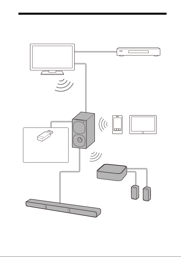
What You Can Do with the Speaker System
“Listening to a TV” (page 19)
Blu-ray Disc™ player, cable
box, satellite box, etc.
“Operating the Speaker System by
Interlocking with a TV (Control for
HDMI function)” (page 28)
“Listening to Music with the
BLUETOOTH® Function”
(page 21)
“Connecting Sony TV with
the BLUETOOTH Function
Wirelessly” (page 16)
TV connection: Refer to “Startup
Guide” (separate document).
“Connecting the Wireless
Amplifier Manually” (page 15)
“Listening to Music
on a USB Device”
(page 19)
Surround speakers
Bar speaker
GB
6

Guide to Parts and Controls
Subwoofer
Front
(power) button
Turns on the speaker system or
sets it to
(input select) button
Selects the input for playback on
the
BLUETOOTH button (pa
+/– (volume) buttons
standby mode.
speaker system.
ge 21)
BLUETOOTH indicator
L
ights in blue: BLUETOOTH
–
connectio
established.
– Flashes slowly in blue
re
connection is being attempted.
– Flashes twice in blue repeatedly:
D
uri
Fr
ont panel display
(US
Remote control sensor
Point the remote control at the
r
em
the speaker system.
n has been
peated
ly: BLUETOOTH
ng pairing standby status.
B) port (page 19)
ote control sensor to operate
GB
7
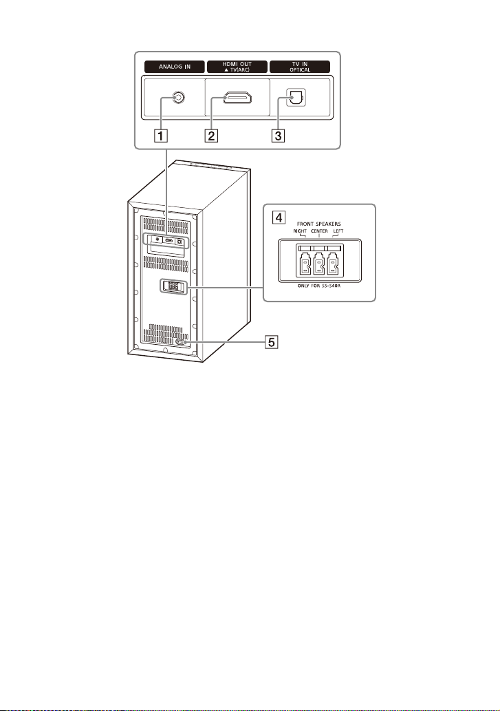
Rear
ANALOG IN jack
HDMI OUT (TV (ARC)) jack
Connect a TV that has an HDMI
np
ut ja ck wi th an HD MI ca bl e. The
i
speaker system is compatible
with Audio Return Channel (ARC).
ARC is the function that sends TV
soun d to an AV device suc h a s the
speaker system from the TV’s
HDMI jack.
TV IN (OPTICAL) jack
FRONT
AC inlet
SPEAKERS jacks
GB
8

Wireless Amplifier
Front Rear
Power indicator
Displays the connecting status
n the subwoofer and
betwee
wireless amplifier, and power
condition of the wireless
amplifier.
Red
– Lights up: The wireless amplifier
tandby mode.
is in s
Green
– Lights up: The wireless amplifier
is
onnected to the subwoofer.
c
– Flashes slowly: The wireless
ampli
er is attempting to
fi
connect to the subwoofer.
Amber
– Lights up: The wireless amplifier
is
c
onnected to the subwoofer
via manual connection.
– Flashes slowly: The wireless
ampli
fi
er is attempting to
connect to the subwoofer via
manual connection.
– Flashes twice repeatedly: The
w
ir
eless amplifier is in pairing
standby status via manual
connection.
– Flashes quickly: The software is
updat
ing.
Tur
ns off
– The wireless amplifier is turned
of
f.
(p
LINK button (pa
SUR SPEAKERS jacks
AC inlet
wer) button
o
s on or off the wireless
Turn
amplifier
.
ge 15)
GB
9
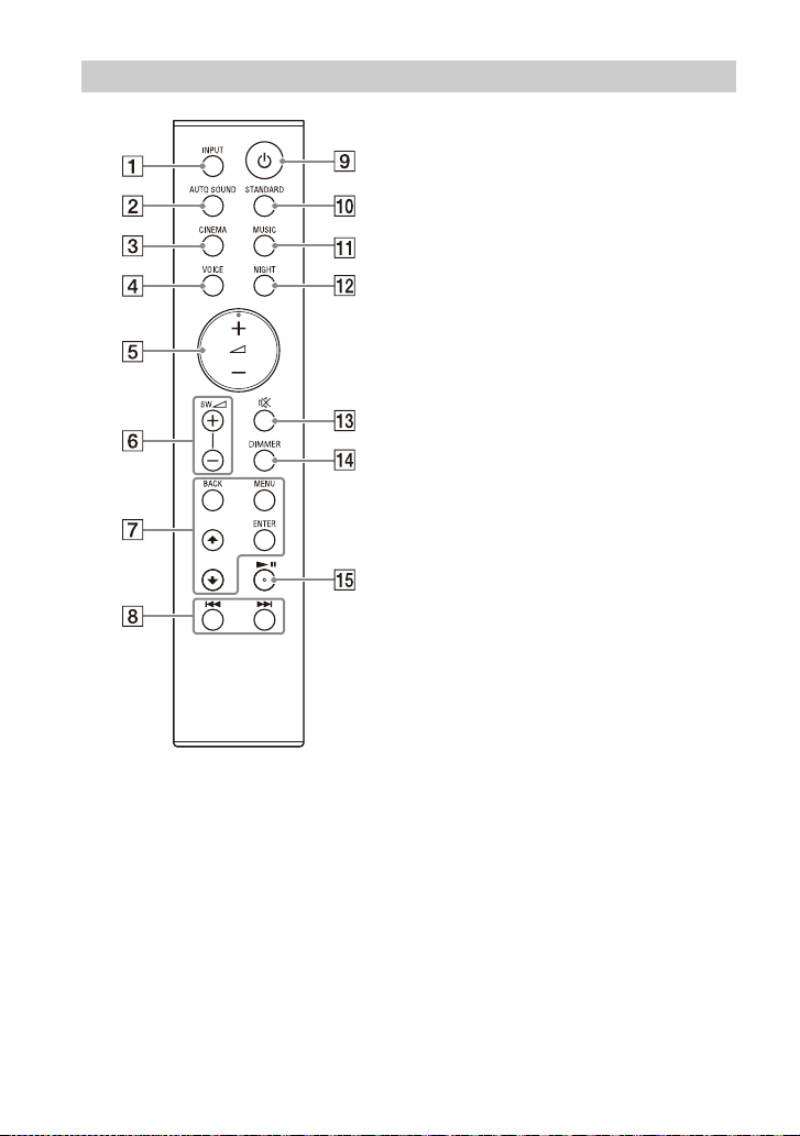
Remote Control
INPUT (pages 19, 23, 24)
Selects the input source.
Each time you press INPUT, the
urce changes cyclically as
input so
follows.
[TV] [ANALOG] [BT
AUTO SOUND (pa
Selects AUTO SOUND for the
sound mode.
CINEMA (pa
Selects CINEMA for the sound
mode.
VOICE
Turns on/off the voice mode.
(volume) +*/–
usts the volume.
Adj
SW (subwoofer volume) +/–
Adj
usts the subwoofer volume.
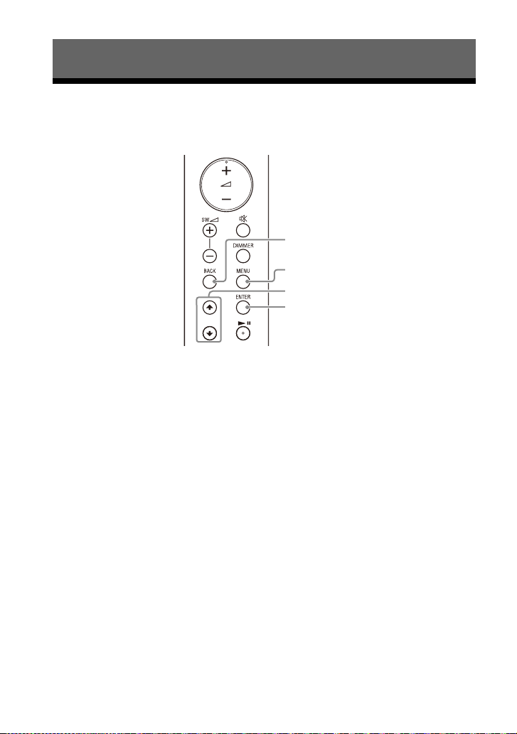
MENU (pages 19, 30)
Turns on/off the setting menu in
ront panel display.
the f
/ (pages 19, 30)
Select
Selects the content on the TV
een for USB playback.
scr
ENTER (pages 19, 30)
Enters the selection.
Plays the content that is selected
by / for
BACK (pages 19, 30)
Returns to the previous display.
Selects the upper layer for USB
playback.
/ (previous/next)
(pag
es 19, 21)
Selects the previous/next track or
file.
Hold dow
forw
ard for USB playback.
ge 25)
ge 26)
(pa
s the setting menu items.
USB playback.
n to search backward or
] [USB]
ge 25)
10
GB

(power)
Turns on the speaker system or
sets it to
standby mode.
STANDARD (page 25)
Selects STANDARD for the sound
mode.
MUS
IC (page 25)
Selects MUSIC for the sound
mode.
NIGHT
(page 26)
Turns on/off the night mode.
(muting)
Mutes the sound temporarily.
Pressing the button while muting
cancels muti
DIMMER (pa
ng.
ge 34)
* (play/pause) (pages 19,
21)
Plays, pauses, or resumes
playba
ck.
*The + and buttons have a tactile
dot. Use it as a guide during operation.
About the replacement of
batteries for the remote control
When the speaker system does not
respond by operating with the remote
control, replace two batteries with new
batteries.
Use R03 (size AAA) manganese batteries
cement.
r repla
fo
GB
11
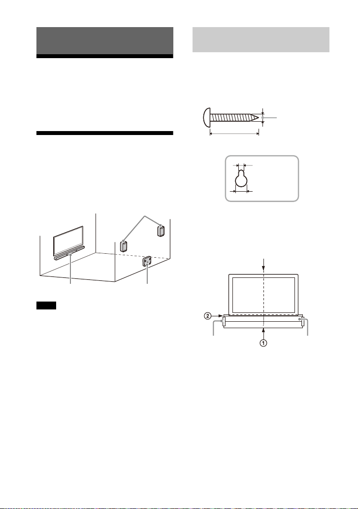
Installation and Connection
Surround speakers
Bar speaker
Wireless amplifier
Hole on the rear of the bar speaker
4 mm (3/16 in)
More than 30 mm (1 3/16 in)
5 mm
(7/32 in)
10 mm
(13/32 in)
Center of the TV
WALL MOUNT
TEMPLATE
Adhesive tape,
etc.
Mounting the Bar Speaker on
a Wall
Basic Installation and
Connection
Refer to Startup Guide (separate
document).
Mounting the Speaker System on a Wall
You can mount the bar speaker,
surround speakers, and wireless
amplifier on a wall.
Notes
• Prepare screws (not supplied) that are
suitable for the wall mate rial and strength.
As a plasterboard wall is especially fragile,
attach the screws securely in the wall
beam. Install the speakers or wireless
amplifier horizontally, hung by screws in
studs in a continuous flat section of the
wall.
• Have the installation done by a Sony
d
er or licensed contractor and pay
eal
special attention to safety during the
installation.
• Sony shall not be held responsible for
a
dents or damage caused by improper
cci
installation, insufficient wall strength,
improper screw installation or natural
disaster, etc.
1 Prepare two screws (not supplied)
that are suitable for the wall
mount holes on the rear of the bar
speaker.
2 Stick WALL MOUNT TEMPLATE
(supplied) on a wall.
1 Align TV CENTER LINE () of
WALL MOUNT TEMPLATE with the
center line of your TV.
2 Align TV BOTTOM LINE () of
WALL MOUNT TEMPLATE with the
bottom of your TV, then stick
WALL MOUNT TEMPLATE on a
wall by using a commercially
available adhesive tape, etc.
GB
12
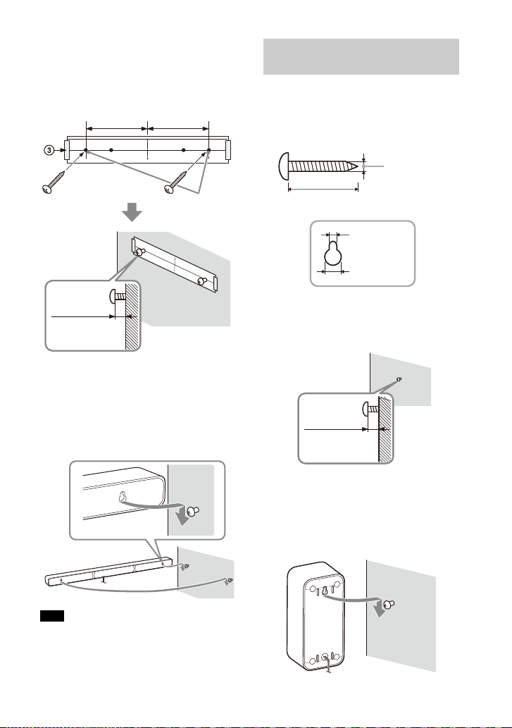
3 Fasten the screws into the marks
Screws
Marks ()
5.5 mm to
6.5 mm
368.5 mm
(14 1/2 in)
368.5 mm
(14 1/2 in)
(approx.
7/32 in)
Hole on the rear of the surround speaker
4 mm (3/16 in)
More than 30 mm (1 3/16 in)
5 mm
(7/32 in)
10 mm
(13/32 in)
6 mm to
7 mm
(approx.
9/32 in)
() on SCREW LINE () of WALL
MOUNT TEMPLATE as in the
illustration below.
4 Remove WALL MOUNT TEMPLATE.
5 Hang the bar speaker on the
screws.
Align the holes on the rear of the bar
sp
the bar speaker on the two screws.
th the screws, then hang
eaker wi
Mounting the Surround
Speakers on a Wall
1 Prepare a screw (not supplied) for
each speaker that is suitable for
the wall mount hole on the rear of
the surround speaker.
2 Fasten the screw on a wall as in the
illustration below.
Note
When sticking WALL MOUNT TEMPLATE,
smooth it out fully.
3 Hang the surround speaker on the
screw.
Align the hole on the rear of the
su
d speaker with the screw,
rroun
then hang the surround speaker on
the screw.
13
GB

Mounting the Wireless
Hole on the bottom of the wireless
amplifier
4 mm (3/16 in)
More than 30 mm (1 3/16 in)
5 mm
(7/32 in)
10 mm
(13/32 in)
Attach the screws apart
from the floor at more than
170 mm (6 3/4 in) so that
the AC power cord (mains
lead) can be attached to the
wireless amplifier.
1.5 mm to
2.5 mm
(approx.
1/16 in)
102 mm
(4 1/8 in)
Amplifier on a Wall
1 Prepare two screws (not supplied)
that are suitable for the wall
mount holes on the bottom of the
wireless amplifier.
2 Fasten the screws on a wall as in
the illustration below.
3 Hang the wireless amplifier on the
screws.
Align the holes on the bottom of the
wireles
s amplifier with the screws,
then hang the wireless amplifier on
the two screws.
14
GB
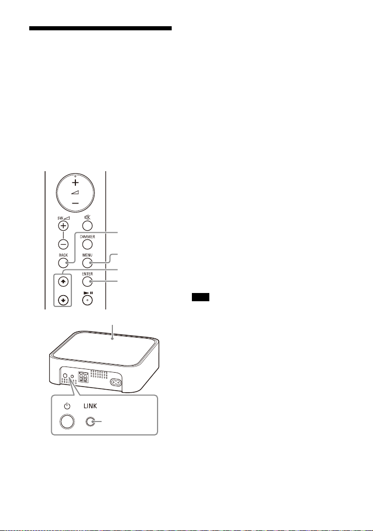
Connecting the Wireless
MENU
/
ENTER
BACK
LINK
Power indicator
Amplifier Manually
The wireless amplifier is connected to
the subwoofer automatically when they
are turned on.
If you cannot connect the wireless
mpl
ifier to the subwoofer
a
automatically, or you use multiple
wireless products and want to specify
the subwoofer that is connected
wirelessly to the wireless amplifier,
perform the manual connection.
1 Press MENU.
[CURRENT STATUS] appears in the
front pa
nel display.
2 Press / to select [SPEAKER],
then press ENTER.
3 Press / to select [LINK], then
press ENTER.
4 Press / to select [START], then
press ENTER.
[LINK] flashes in the front panel
di
y.
spla
To cancel the manual connection,
ss BA
pre
CK.
5 Press LINK on the wireless
amplifier.
The manual link starts.
The power indicator of the wireless
amplif
ier flashes twice in amber
repeatedly.
6 When [DONE] appears in the front
panel display, press MENU.
The link is established and the
po
ndicator of the wireless
wer i
amplifier lights in amber.
Note
If [ERROR] appears in the front panel
display, the connection of the wireless
amplifier has not been established.
Perform the manual connection again.
15
GB
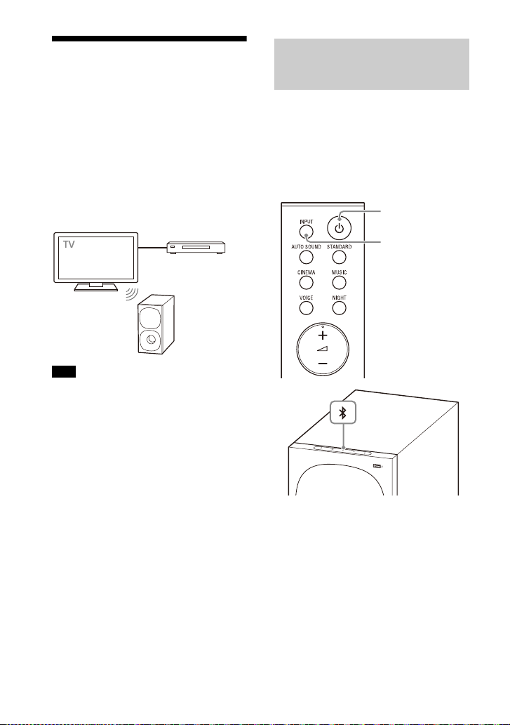
Connecting Sony TV with
Blu-ray Disc play er,
cable box, satellite
box, etc.
INPUT
BLUETOOTH
button
the BLUETOOTH Function
Wirelessly
When using Sony TV* with the
BLUETOOTH function, you can listen to
sound of the TV or device that is
connected to the TV by connecting the
speaker system and TV wirelessly.
* Th e T V ne eds to be c om pat ibl e w ith A2 DP
(Advanced Audio Distribution Profile) of
the BLUETOOTH profile.
Note
If connecting the speaker system and TV by
using t
he BLUETOOTH function, you cannot
display the USB playback screen on the TV
screen.
To use all the functions of the speaker
sys
tem, connect the speaker system and TV
with an HDMI cable. For details about
connections and operations to listen to TV
sound by connecting with an HDMI cable,
refer to Startup Guide (separate
document).
Listening to TV Sound by
Connecting the Speaker
System and TV Wirelessly
You need to perform pairing of the
speaker system and TV by using the
BLUETOOTH function.
Pairing is the process required to
utu
ally register the information on
m
BLUETOOTH devices to be connected
wirelessly in advance.
1 Turn on the TV.
2 Turn on the speaker system.
3 Press and hold the BLUETOOTH
button on the subwoofer and
INPUT on the remote control
simultaneously for 5 seconds.
The speaker system enters the
pa
ing mode, [PAIRING] appears in
ir
the front panel display, and the
BLUETOOTH indicator flashes twice
in blue repeatedly.
16
GB

4 On the TV, search the speaker
system by performing the pairing
operation.
The list of the BLUETOOTH devices
t
are searched appears on the TV
hat
screen.
For the operation method to pair the
BLUE
TOOTH device to the TV, refer
to the operating instructions of the
TV.
5 Pair the speaker system and TV by
selecting “HT-S40R” from the list
on the TV screen.
6 Make sure that the BLUETOOTH
indicator on the subwoofer lights
in blue and [TV-BT] appears in the
front panel display.
A connection between the speaker
sy
em and TV has been
st
established.
7 Select the program or input of the
device by using the TV remote
control.
The sound of the displayed image
o
e TV screen is output from the
n th
speaker system.
8 Adjust the volume of the speaker
system by using the TV remote
control.
When pressing the muting button
on
e TV remote control, the sound
th
is muted temporarily.
Notes
• If the TV sound is not output from the
speaker system, select the TV input by
pressing INPUT and check the status of
the front panel display and indicators on
the subwoofer.
– [TV-BT] appears in the front panel
disp
lay: The speaker system and TV are
connected and TV sound is output from
the speaker system.
– The BLUETOOTH indicator flashes twice
rep
edly and [PAIRING] app ears in the
eat
front panel display: Perform pairing on
the TV.
– [TV] appears in the front panel display:
Perfor
m steps from the start.
• When you connect the speaker system
and T
V with an HDMI cable, the
BLUETOOTH connection is canceled. To
connect the speaker system and TV with
the BLUETOOTH function again,
disconnect the HDMI cable, then perform
the connecting operation from the start.
• While the speaker system is connecting
the
with the BLUETOOTH function and
TV
[AUTO SOUND] is selected for the sound
mode, [STANDARD] is selected for the
sound mode.
GB
17

Listening to Sound of the
Paired TV
You can turn the speaker system on/off,
adjust the volume, and mute the sound
by using the TV remote control when
connecting the TV to the speaker system
wirelessly.
1 Turn on the TV with the TV remote
control.
The speaker system is turned on by
i
ocking with the TV power, and
nterl
TV sound is output from the speaker
system.
2 Select the program or input of the
device by using the TV remote
control.
The sound of the displayed image
o
e TV screen is output from the
n th
speaker system.
3 Adjust the volume of the speaker
system by using the TV remote
control.
When pressing the muting button
o
e TV remote control, the sound
n th
is muted temporarily.
Note
If you select the input other than [TV] on the
remote control supplied with the speaker
system, the TV sound is not output from the
speaker system. To output the TV sound,
select the TV input by pressing INPUT.
Tip
When the TV is turned off, the speaker
system is also turned off by interlocking
with the TV power.
18
GB

Listening to Music/Sound
INPUT
SW +/–
+/–
INPUT
SW +/–
+/–
MENU
/
ENTER
/
BACK
Listening to a TV
1 Press INPUT repeatedly to select
[TV] in the front panel display.
2 Adjust the volume.
• Adjust the volume by pressing
+/–.
• Adjust the subwoofer volume by
pres
Notes
• When you connect the TV to both the
HDMI OUT (TV (ARC)) and TV IN (OPTICAL)
jacks, the jack for audio input is selected
depending on which audio signal is input
first.
• When the input source does not contain
much
bass sound, such as in TV programs,
the bass sound from the subwoofer may
be difficult to hear.
Tip
You can also select the input by pressing
on the subwoofer.
sing SW +/–.
Listening to Music on a USB Device
Notes
• To view the USB content list on the TV
screen, make sure you connect the
speaker system to the TV using an HDMI
cable.
• Change the input of the TV to the input to
w
ch the speaker system is connected.
hi
19
GB

1 Connect the USB device to the
(USB) port.
2 Press INPUT repeatedly to select
[USB] in the front panel display.
[READ] appears in the front panel
displa
y and the speaker system
starts reading data of the USB
device. When the reading of data is
completed, the USB content list
appears on the TV screen.
3 Press / to select the content you
want, then press ENTER.
The selected content starts playing.
You can go to the upper layer by
pressing BA
CK.
4 Adjust the volume.
• Adjust the volume by pressing
+/–.
• Adjust the subwoofer volume by
Note
When the input source does not contain
much bass sound, such as in TV programs,
the bass sound from t he subwoofer may be
difficult to hear.
pressing
SW +/–.
To select the play mode
You can select the play mode for USB
playback, such as repeat play or random
play, from the setting menu.
1 Press MENU.
[CURRENT STATUS] appears in the
front pa
nel display.
2 Press //ENTER to select [USB] -
[REPEAT].
3 Press //ENTER to select the play
mode.
• [OFF]: Repeat off. Plays back all
tra
s.
ck
• [ONE]: Repeats one track.
• [FOLDER]: Repeats all tracks in the
urre
nt folder.
c
• [RANDOM]: Repeats all tracks in
e c
urrent folder in random order.
th
• [ALL]: Repeats all tracks.
4 Press MENU to exit the setting
menu.
Other operations
To Do this
Pause or resume
play
back
Select the previous
or ne
xt track
Search backward or
rewind/
forward (
fast forward)
Notes
• Do not remove the USB device during
operation. To avoid data corruption or
damage to the USB device, turn the
speaker system off before connecting or
removing the USB device.
• [INVALID USB] appears in the front panel
disp
lay if you connect an unsupported or
broken USB device.
• Depending on the file format, rewind and
fast fo
rward may not work.
Press .
Press /.
Press and hold /
.
20
GB

Information of USB Device on the
SW +/–
+/–
/
TV Screen
Playing time
Total playing time
Bit rate
Playback status
Rewind/fast forward speed
Play mode
Selected file index/Total files in the
lder
fo
T
he following messages appear on the
TV s
creen depending on the status of
the USB device.
• [File Unsupported]
Appears for 2 seconds at the bottom
side when an unsupported file is
ft
le
skipped.
•[Device Not Support]
– A USB device is not supported.
– Device inserted is a non-USB device,
bad
USB device, or a USB device
a
that has no files on it.
•[No USB]
No USB device is inserted.
•[Waiting]
The speaker system is searching the
devi
USB
• [This device is empty]
There are no playable files in the USB
de
Notes
• Depending on the playback source, some
information may not be displayed.
• Depending on the play mode, the
inform
ce.
vi
ce.
ation displayed may differ.
Listening to Music with the BLUETOOTH® Function
Listening to Music by Pairing
the Mobile Device that is
Connected for the First Time
To use the BLUETOOTH function, you
need to perform pairing of the speaker
system and mobile device in advance.
21
GB

1 Press and hold the BLUETOOTH
BLUETOOTH
button
button on the subwoofer for 2
seconds.
The speaker system enters the
pa
ing mode, [PAIRING] appears in
ir
the front panel display, and the
BLUETOOTH indicator flashes twice
in blue repeatedly.
2 On the mobile device, search for
the speaker system by performing
the pairing operation.
The list of the BLUETOOTH devices
t
are searched appears on the
hat
screen of the mobile device.
For the operation method to pair the
BLUE
TOOTH device to the mobile
device, refer to the operating
instructions of the mobile device.
3 Pair the speaker system and
mobile device by selecting “HTS40R” from the list on the screen of
the mobile device.
If a Passkey is requested, enter
“00
00.”
4 Make sure that the BLUETOOTH
indicator on the subwoofer lights
in blue and [BT] appears in the
front panel display.
A connection between the speaker
syst
established.
nd mobile device has been
em a
5 Start audio playback with the
music app on the connected
mobile device.
Sound is output from the speaker
sy
.
stem
6 Adjust the volume.
• Adjust the volume by pressing
+/–.
• Adjust the subwoofer volume by
pressing S
• an
for the BLUETOOTH function.
(Searching backward or forward by
holding down / does not
work.)
Notes
• You can pair the BLUETOOTH devices up
to the following number.
–Mobile devices: 9
– Sony TV with the BLUETOOTH function: 1
If a new device is paired after pairing the
above numb
connected device will be replaced by the
new one.
• Perform pairing for the second and
subsequent
• When the input source does not contain
much ba
the bass sound from the subwoofer may
be difficult to hear.
Tips
• You can check the connection status of
the BLUETOOTH function by checking the
BLUETOOTH indicator status.
• While the BLUETOOTH input is being
sel
ected, the speaker system enters the
pairing mode by pressing the BLUETOOTH
button on the subwoofer shortly.
W +/–.
d / ca
er of devices, the oldest
mobile devices.
ss sound, such as in TV programs,
n be used
22
GB

Listening to Music from the
INPUT
SW +/–
+/–
/
Paired Device
1 Turn the BLUETOOTH function of
the mobile device on.
2 Press INPUT repeatedly to select
[BT] or shortly press the
BLUETOOTH button on the
subwoofer.
The BLUETOOTH indicator flashes
a
nd the spe
automatically reconnects to the
BLUETOOTH device it was most
recently connected to.
3 Make sure that the BLUETOOTH
indicator lights in blue.
A connection between the speaker
sys
tem
established.
aker system
and mobile device has been
4 Start audio playback with the
music app on the connected
mobile device.
Sound is output from the speaker
sy
em.
st
5 Adjust the volume.
• Adjust the volume by pressing
+/–.
• Adjust the subwoofer volume by
ssing SW +/–.
pre
• and
for the BLUETOOTH function.
(Searching backward or forward by
holding down / does not
work.)
Note
When the input source does not contain
much bass sound, such as in TV programs,
the bass sound from t he subwoofer may be
difficult to hear.
Tip
When the connection is not established,
select “HT-S40R” on the mobile device.
To disconnect the mobile device
Perform any of the following items.
• Disable the BLUETOOTH function on
the mo
• Set [BT] - [POWER] to [OFF] (page 32).
• Turn off the speaker system or mobile
vi
ce.
de
/ ca
bile device.
n be used
23
GB

Listening to Music on an
INPUT
SW +/–
+/–
Smartphone,
WALKMAN®, other
audio devices, etc.
Analog audio cable
(not supplied)
Audio Device Connected
with a Stereo Mini Cable
1 Connect an audio device to the
ANALOG IN jack.
3 Start music playback by operating
the connected audio device.
Sound is output from the speaker
system
.
4 Adjust the volume.
• Adjust the volume by pressing
+/–.
• Adjust the subwoofer volume by
pressing S
Note
When the input source does not contain
much bass sound, such as in TV programs,
the bass sound from the subwoofer may be
difficult to hear.
W +/–.
2 Press INPUT repeatedly to select
[ANALOG] in the front panel
display.
24
GB

Adjusting the Sound Quality
CINEMA
MUSIC
AUTO SOUND
STANDARD
Setting the Sound Effect that is Tailored to Sound Sources (Sound Mode)
You can easily enjoy pre-programmed
sound effects that are tailored to
different kinds of sound sources.
1 Press one of the sound mode
selecting buttons (AUTO SOUND,
STANDARD, CINEMA, MUSIC) to
select the sound mode.
Button Function
AUTO SOUND
STANDARD
[AUTO SOUND]
appears in the front
panel display.
The appropriate
sou
nd mode setting
is automatically
selected from
STANDARD,
CINEMA, or MUSIC.
[STANDARD]
appears in the front
panel display.
Sound effects are
opti
mized for the
individual source.
Button Function
CINEMA
MUSIC
[CINEMA] appears in
the front panel
display.
Sounds are played
back w
effects, and they are
realistic and
powerful, making
them suitable for
movies.
[MUSIC] appears in
the front panel
display.
Sound effects are
opti
mized for
listening to music.
ith surround
25
GB
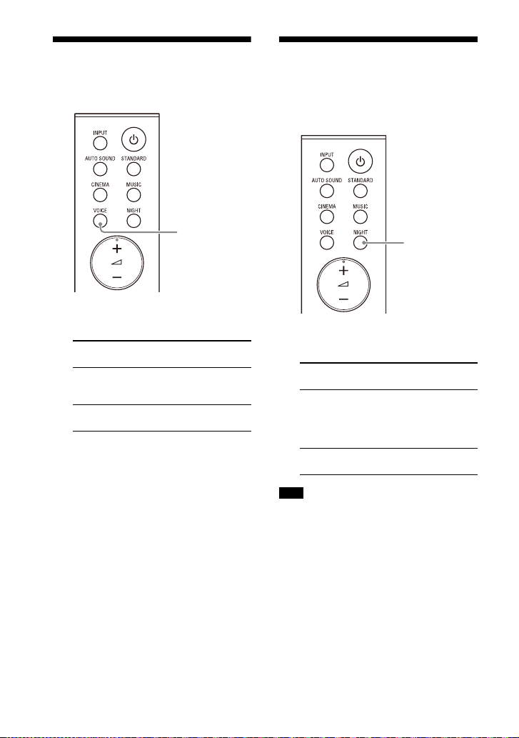
Making Dialogs Clearer
VOICE
NIGHT
(VOICE)
1 Press VOICE to set the function on
or off.
Front panel
display
[Vo.ON] Dialog is easily heard
[Vo.OFF] Deactivates the voice
Function
by enha
ncing dialog
range.
mode function.
Enjoying Clear Sound with Low Volume at Midnight (NIGHT)
1 Press NIGHT to set the function on
or off.
Front panel
display
[N.ON] Outputs the sound at
[N.OFF] Deactivates the night
Function
lume with
low vo
minimum loss of
fidelity and clarity of
dialog.
de func
mo
tion.
26
Note
When you turn the speaker system off, this
setting is set to [N.OFF] automatically.
GB

Checking the Current
MENU
/
ENTER
Sound Settings
You can check the settings of the sound,
night, and voice modes and current
stream information.
1 Press MENU.
[CURRENT STATUS] appears in the
front p
anel display, then press
ENTER.
2 Press repeatedly to select the
item you want.
The current setting appears in the
f
owing order.
oll
Sound mode Vo
Night mode Stream Information
The current setting appears in the
verse
order by pressing .
re
ic
e mode
3 Press MENU to exit the setting
menu.
27
GB

Using the Speaker System by
TV remote control
Interlocking with a TV
• If you enable the Control for HDMI
(“BRAVI
A” sync) function when using a TV
manufactured by Sony, the Control for
HDMI
function of the speaker system is
also ena
bled automatically.
Operating the Speaker System by Interlocking with a TV (Control for HDMI function)
Connecting a TV compatible with the
Control for HDMI function using an HDMI
cable enables you to interlock the
speaker system opera tion such as power
on/off or volume adjustment with a TV.
About the Control for HDMI
function
The Control for HDMI function is a
function that enables operation of
devices connected with an HDMI (HighDefinition Multimedia Interface) cable by
interlocking each other.
Although this function works for devices
atible with the Control for HDMI
omp
c
function, it may not work if connecting
devices other than those manufactured
by Sony.
Preparing to Operate by
Interlocking with a TV
Enable the Control for HDMI function
ttin
gs of the TV connected to the
se
speaker system with an HDMI cable.
The default setting of the Control for
MI fun
HD
[ON] (page 32).
Tips
• When connecting a device such as a Blu-
• To enable the Control for HDMI function of
ction of the speaker system is
ra y D isc pl aye r to a T V w ith an H DM I ca bl e,
enable its Control for HDMI function.
a TV o
r Blu-ray Disc player, refer to their
operating instructions.
Performing Power Operation
or Volume Adjustment by a
TV Remote Control
When performing TV power operation or
volume adjustment by a TV remote
control, the speaker system power
operation or volume adjustment is
interlocked.
Power interlocking
When you turn on or off the TV, the
speaker system will turn on or off
automatically.
Note
If you turn off the speaker system before
turning off the TV, the speaker system may
not turn on automatically even though you
turn on the TV next time. In this case,
perform the following operation.
– Select the speaker system for the sound
out
put device in the TV menu.
– When using Sony TV, turn on the
spea
ker system while the TV is turned
on.
28
GB

Volume adjustment
The TV sound that you are watching is
output from the speaker system
automatically. You can adjust the
speaker system volume by the TV
remote control.
Other Interlocking Function
One-Touch Play Function
When you play content on a Blu-ray Disc
player or “PlayStation
to the TV, the speaker system and TV are
turned on automatically.
Tip
You can change the Control for HDMI
function setting on [HDMI] - [CONTROL FOR
HDMI] (page 32) in the setting menu.
4,” etc. conn ected
®
29
GB
Changing the Settings
MENU
/
ENTER
BACK
Using the Setting Menu
You can set the following items with the setting menu. Your settings are retained even
if you disconnect the AC power cord (mains lead).
1 Press MENU to enter the setting menu mode.
The setting menu item appears in the front panel display.
2 Press / repeatedly to select the item, then press ENTER.
You can select the following items.
• [CURRENT STATUS] (Checking the current status) (page 31)
• [SPEAKER] (Speaker settings) (page 31)
• [AUDIO] (Audio settings) (page 32)
• [HDMI] (HDMI settings) (page 32)
• [BT] (BLUETOOTH settings) (page 32)
• [USB] (USB settings) (page 32)
• [SYSTEM] (Speaker system settings) (page 33)
• [RESET] (Resetting the speaker system) (page 33)
• [UPDATE] (Updating the speaker system) (page 33)
3 Press / repeatedly to select the setting, then press ENTER.
To return to the upper layer, press BACK.
4 Press MENU to exit the setting menu mode.
30
GB

Setting menu items
Items Function
[CURRENT
S]
STATU
(Checking the
nt status)
curre
[SPEAKER]
(Speaker
ings)
sett
[AUTO SOUND]/
[STA
NDARD]/
[CINEMA]/[MUSIC]
(Sound mode)
[Vo. ON]/[Vo.OFF]
(Voice mode)
[N.ON]/[N.OFF]
(Night mode)
[NO INFO.]/
PC
M]/
[L
[DOLBY DIGITAL]
(Stream
fo
rmation)
in
[MULTI SPEAKER] • [ON]: Outputs the sound from all the speakers, regardless
[SUR.L.DISTANCE]/
R.R.DISTANCE]
[SU
(Surround speaker
nce)
dista
[DISTANCE UNIT] Changes measurement units (meters or feet) for
[SUR.L.LEVEL]/
R.R.LEVEL]
[SU
(Surround speaker
)
level
[TEST TONE] [ON]: Outputs the test tone from each speaker in sequence.
[LINK] • [START]: Performs the manual connection of the wireless
These items are not setting menu items.
You can check the settings of the sound, night, and voice
mode
For details about operation, see “Checking the Current
Sound Settings” (page 27).
of th
• [OFF]:Outputs the sound from the speakers that
corre
Adjusts the distance from the seating position to the
surro
und speaker (left or right) from 1.0 meter to 6.0 meters
(0.1 meter intervals) (from 3.0 feet to 20.0 feet (3 inch
intervals)).
Note
You can change measurement units (meters or feet) on
[DISTANCE UNIT].
.L.DISTANCE]/[SUR.R.DISTANCE].
[SUR
•[METER]: Meter display.
• [FEET]: Feet display.
Adjusts the sound level of the surround speaker (left or
right) fro
Note
Be sure to set [TEST TONE] to [ON] for easy adjustment.
[OFF]: Turns off the test tone.
Note
The test tone is not output even though [TEST TONE] is set
to [ON] while the [USB] input is selected. Select an input
other than [USB].
ampli
the Wireless Amplifier Manually” (page 15).
To cancel the manual connection, press BACK.
• [CANCEL]: Returns to the upper layer [LINK].
s and current stream information.
e number of audio channels for the playback source.
spond to the audio channel for the playback source.
m –6.0 dB to +6.0 dB (0.5 dB intervals).
fier to the subwoofer. For details, see “Connecting
31
GB

Items Function
[AUDIO]
(Audio
ings)
sett
[HDMI]
(HDMI
ings)
sett
[BT]
(BLUETOOTH
ings)
sett
[USB]
(USB settings)
[DRC]
(Dynamic range
control)
[A.VOL]
(Auto volume)
[DUAL]
(Dual mono)
[CONTROL FOR
HDMI]
[TV AUDIO] You can set whether the playback sound is input from an
[POWER] • [ON]: Turns the BLUETOOTH function on.
[STANDBY] When the speaker system has pairing information, you can
[REPEAT]
(Repeat play
)
mode
Useful for enjoying movies at low sound volume. DRC
applie
s to Dolby Digital sources.
• [ON]: Compresses sound according to the information in
ontent.
the c
• [OFF]: Sound is not compressed.
Adjusts the volume automatically depending on the input
l from a connected device.
leve
• [ON]: Adjusts the volume automatically.
• [OFF]: Off.
You can enjoy multiplex broadcast s ound when the speaker
tem receives a Dolby Digital multiplex broadcast signal.
sys
• [MAIN]: Sound of the main language will be output.
• [SUB]: Sound of the sub language will be output.
• [M/S]: Mixed sound of both the main and sub languages
will b
Note
To receive a Dolby Digital signal, you need to connect a TV
or other device to the TV IN (OPTICAL) jack with an optical
digital cable or the HDMI OUT (TV (ARC)) jack with an HDMI
cable.
[ON]: Enables the Control for HDMI function. Devices
•
connected with an HDMI cable can operate each other.
[OFF]: Disables the Control for HDMI function.
•
I cable or optical digital cable.
HDM
• [AUTO]: Plays the sound that is detected from either an
I cable or optical digital cable. When you connect
HDM
either an HDMI cable or optical digital cable, the speaker
system plays by selecting the connected cable for the TV
input.
• [OPTICAL]: Plays the sound from the TV IN (OPTICAL) jack
for the
• [OFF]: Turns the BLUETOOTH function off.
Note
When the BLUETOOTH f unction is set to off, the BLUETOOTH
input is skipped while selecting input by pressing INPUT.
n the speaker system on and listen to music from a
tur
BLUETOOTH device, even when the speaker system is in
standby mode, by setting the BLUETOOT H standby mode to
on.
• [ON]: Enables the BLUETOOTH standby mode.
• [OFF]: Disables the BLUETOOTH standby mode.
Note
While the BLUETOOTH standby mode is on, standby power
consumption increases.
• [OFF]: Repeat off. Plays back all tracks.
• [ONE]: Repeats one track.
• [FOLDER]: Repeats all tracks in the current folder.
• [RANDOM]: Repeats all tracks in the current folder in
dom order.
ran
• [ALL]: Repeats all tracks.
e output.
TV input.
32
GB

Items Function
[SYSTEM]
(Speaker
m
syste
settings)
[RESET]
(Resetting the
speaker
system)
[UPDATE]
(Updating the
ker
spea
system)
[AUTO STANDBY] • [ON]: Turns on the auto standby function. When you do
[VERSION]
(Version
fo
rmation)
in
[SUR. AMP. INFO]
(Wireless amplifier
sio
n
ver
information)
[ALL RESET] You can reset the speaker system settings to the factory
[START] You can start software update after connecting the USB
ot o
n
speaker system enters standby mode automatically.
• [OFF]: Off.
The current firmware version information of the speaker
system
• [LATEST]: The wireless amplifier is the latest version.
• [PLEASE UPDATE]: The wireless amplifier is not the latest
sion.
ver
• [NOT CONNECTED]: The wireless amplifier is not connected
e subwoofer.
to th
default. Fo
(page 41).
memory
speaker system. When there is a software update available,
we will notify you on the following website:
• For customers in Americas
https://www.sony.com/am/support
• For customers in Europe
https://www.sony.eu/support
• For customers in Asia-Pacific, Oceania, Middle East, and
ric
a
Af
https://www.sony-asia.com/support
Note
Before updating, make sure that the wireless amplifier
is t
urned on and connected to the subwoofer.
[CANCEL] Returns to the upper layer [UPDATE].
perate the speaker system for about 20 minutes, the
appears in the front panel display.
r details, see “Resetting the Speaker System”
on which the software update file is stored to the
33
GB

Changing the Brightness
DIMMER
of the Front Panel Display
and Indicators (DIMMER)
You can change the brightness of the
following.
• Front panel display
• BLUETOOTH indicator
• Power indicator on the wireless
fier
li
amp
Saving Power Consumption
To use the speaker system with saving
power consumption, change the
following settings.
Turning the Speaker System
Off by Detecting the Using
State
When you set the auto standby function
e speaker system enters
to on, th
standby mode automatically when you
do not operate the speaker system for
about 20 minutes and the speaker
system is not receiving an input signal.
1 Set [SYSTEM] – [AUTO STANDBY] to
[ON].
1 Press DIMMER repeatedly to select
the desired setting.
Front panel
display
[BRIGHT] The front panel
[DARK] The front panel
[OFF] The front panel
Note
The front panel display is turned off when
[OFF] is selected. It turns on automatically
when you press any button, then turns off
again if you do not operate the speaker
system for about 10 seconds. However, in
some cases, the front panel display may
not turn off. In this case, the brightness of
the front panel display is same as [DARK].
GB
34
Function
y and indicators
displa
light brightly.
display and indicators
light darkly.
lay is turned off.
disp
Saving Power in Standby
Mode
To save power consumption during the
standby
mode, set [BT] - [STANDBY] to
[OFF] (page 32).

Troubleshooting
Troubleshooting
If the speaker system does not work
properly, handle it in the following order.
1 Search for the cause and solution of
the issue using this troubleshooting.
2 Reset the speaker system.
All the settings of the speaker system
return to
details, see “Resetting the Speaker
System” (page 41).
Should any problems persist, consult
y
our ne
Be sure to bring your bar speaker,
bwoo
su
surround speakers even if it seems as
though only one has a problem, when
you request to repair.
Power
The speaker system does not power
up.
Check that the AC power cord (mains
lead) is connected securely.
Di
lead
then reconnect after several minutes.
The speaker system is turned off
automatically.
The auto standby function is working.
Set [SYSTEM] - [AUTO STANDBY] to
[OFF] (page 33).
The speaker system does not turn
on even when the TV is turned on.
Set [HDMI] - [CONTROL FOR HDMI] to
[ON] (page 32). The TV must support
the Control for HDMI function. For
det
instructions of your TV.
their initial status. For
arest Sony dealer.
fer, wireless amplifier, and
sconnect the AC power cord (mains
) from the wall outlet (mains), and
ails, refer to the operating
Check the speaker settings of the TV.
Th
e speaker system power syncs with
the speaker settings of the TV. For
details, refer to the operating
instructions of your TV.
D
epending on the TV, if the sound
was
output from the speakers of the
TV the previous time, the speaker
system may not turn on by
interlocking with the TV power even
when the TV is turned on.
The speaker system turns off when
the TV is turned off.
Check the setting of the Control for
HDMI function (page 32). When the
Control for HDMI function is set to on
and t
he input of the speaker system is
the TV input, the speaker system turns
off automatically when you turn off
the TV.
The speaker system does not turn
off even when the TV is turned off.
Check the setting of the Control for
HDMI function (page 32). When you
turn off the TV, the speaker system
turns
f automatically only if the
of
input of the speaker system is TV
input. The TV must support the
Control for HDMI function. For details,
refer to the operating instructions of
your TV.
Picture
There is no picture or the picture is
not output correctly.
Select the appropriate input.
When there is no picture while the TV
inp
ut is selected, select the TV
channel that you want using the TV
remote control.
Di
sconnect an HDMI cable, then
co
nnect it again. Make sure that the
cable is firmly inserted.
35
GB

Sound
The speaker system cannot connect
to a TV with the BLUETOOTH
function.
When you connect the speaker
system and TV with an HDMI cable,
the BLUETOOTH connection is
canceled. Disconnect the HDMI cable,
then perform the connecting
operation from the start (page 16).
No TV sound is output from the
speaker system.
Check the type and connection of an
HDMI cable or optical digital cable
that is connected to the speaker
system and the TV (refer to the
supplied Startup Guide).
Di
sconnect the cables that are
co
nnected between the TV and the
speaker system, then connect them
firmly again. Disconnect the AC power
cords (mains leads) of the TV and the
speaker system from the wall outlets
(mains), then connect them again.
Wh
en the speaker system and TV are
nnected with an HDMI cable only,
co
check the following.
– T he HD MI ja ck of the co nn ec te d T V i s
la
led with “ARC.”
be
– The Control for HDMI function of the
V i
s set to on.
T
– The ARC function of the TV is
abl
ed.
en
– On the speaker system, the Control
r HD
MI function is set to on
fo
(page 32).
our TV is not compatible with
If y
Au
dio Return Channel, connect an
optical digital cable (refer to the
supplied Startup Guide). If the TV is
not compatible with Audio Return
Channel, TV sound will not be output
from the speaker system even if the
speaker system is connected to the
TV’s HDMI IN jack.
I
f the sound of the device that is
nnected to an optical input jack of
co
the TV is not output, try the following.
– Connect the cable box or satellite
bo
rectly to the TV IN (OPTICAL)
x di
jack of the speaker system.
ss INPUT repeatedly to select the
Pre
TV in
put (page 19).
Increase the volume on the TV or
canc
el muting.
D
epending on the order in which you
n the TV and speaker system,
turn o
the speaker system may be muted. If
this happens, turn on the TV first, then
the speaker system.
S
et the speaker setting of the TV
(B
RAVIA) to Audio System. Refer to
the operating instructions of your TV
regarding how to set the TV.
C
heck the sound output of the TV.
Refe
r to the operating instructions of
the TV for the TV settings.
T
he speaker system supports the
lby Digital and PCM audio formats.
Do
When you play back an unsupported
format, set the digital audio out
setting of the TV (BRAVIA) to “PCM.”
For details, refer to the operating
instructions of your TV.
The sound is output from both the
speaker system and TV.
Change the audio output setting of
the TV so that the TV sound is output
from the external speaker.
S
et the TV volume to minimum.
No sound or only a very low-level
sound is heard from the subwoofer.
Make sure the AC power cord (mains
lead) of the subwoofer is connected
properly (refer to the supplied Startup
Guide).
ss SW +
Pre
to increase the subwoofer volume
(page 10).
subwoofer is for reproducing bass
A
sound.
very little bass sound components
(i.e., a TV broadcast), the sound from
the subwoofer may be difficult to
hear.
on the remote control
If the input sources contain
36
GB

When you play content compatible
with copyright protection technology
(HDCP), it is not output from the
subwoofer.
No sound or only a very low-level
sound of the device connected to
the speaker system is heard from
the speaker system.
Press + and check the volume level
(page 10).
Press or +
function (page 10).
M
ake sure the input source is selected
rrectly. You should try other input
co
sources by pressing INPUT repeatedly.
C
heck that all the cables and cords of
e speaker system and connected
th
device are firmly inserted.
If the connected device supports the
up-sam
it off.
to cancel the muting
pling feature, you need to turn
The surround effect cannot be
obtained.
Depending on the input signal,
surround sound processing may not
work effectively. The surround effect
may be subtle depending on the
program or disc.
To
play multi channel audio, check the
digi
tal audio output setting on the
device connected to the speaker
system. For details, refer to the
operating instructions of the
connected device.
The output sound of the speaker
system is not the same level as that
of the TV even though the values of
the volume level on the speaker
system and TV are set to the same
value.
If the Control for HDMI function is set
to on, the value of the volume level on
the speaker system may appear on
your TV as the TV volume. The output
sound levels of the speaker system
and TV differ even though the values
of the volume level on the speaker
system and TV are set to the same
value. The output sound levels of the
speaker system and TV differ
depending on the sound processing
characteristics of each, and it is not a
malfunction.
The sound is interrupted while
watching a TV program or content
on a Blu-ray Disc, etc.
Check the sound mode setting
(page 25). If the sound mode is set to
[AUTO SOUND], the sound may be
interru
pted when the sound mode is
changed automatically according to
the information of the program that is
being played. If you do not want to
change the sound mode
automatically, set the sound mode to
a setting other than [AUTO SOUND].
The TV sound from the speaker
system lags behind the image.
A time gap between the sound and
picture may occur depending on the
sound source. If your TV has a
function that delays the image, use it
for adjustment.
Wireless Amplifier
No sound or only a very low-level
sound is heard from the wireless
amplifier.
Make sure that the power indicator on
the wireless amplifier is lit in green or
amber.
f the power indicator on the wireless
I
amp
lifier does not light, try the
following.
– Make sure the AC power cord (mains
ad)
of the wireless amplifier is
le
connected properly.
– Press (
amplifier to turn on the power.
f the power indicator on the wireless
I
am
amber, or lights in red, try the
following.
– Move the wireless amplifier to a
l
pow
er) of the wireless
plifier flashes slowly in green or
ation near the subwoofer so that
oc
37
GB

the power indicator on the wireless
amplifier lights in green or amber.
– Follow the steps in “Connecting the
Wireless Amplifier Manually”
(page 15).
f the power indicator on the wireless
I
am
plifier flashes in red, press
(power) of the wireless amplifier to
turn off the power and check whether
the ventilation holes of the wireless
amplifier is blocked or not.
eck that [SPEAKER] – [MULTI
Ch
SP
EAKER] is set to [ON] (page 31). If
[SPEAKER] – [MULTI SPEAKER] is set to
the sound is not output from
[OFF],
the surround speakers when playing
the sound of 2-channel source.
Sound skips or has noise.
If there is a device nearby that
generates electromagnetic waves,
such as a wireless LAN or a microwave
oven in use, locate the speaker
system apart from it.
there is an obstacle between the
If
subw
oofer and the wireless amplifier,
move or remove it.
o not cover the top of the subwoofer
D
wit
h metal objects such as TV frame,
etc. Wireless functions may become
unstable.
cate the subwoofer and the
Lo
less amplifier as close to each
wire
other as possible.
witch the wireless LAN frequency of
S
any
nearby wireless LAN router or PC
to 5 GHz range.
witch the network connection of the
S
TV or
Blu-ray Disc player from wireless
to wired.
USB Device Connection
The USB device is not recognized.
Try the following:
Turn the speaker system off.
Remove and reconnect the USB
v
ice.
de
urn the speaker system on.
T
Make sure that the USB device is
se
curely connected to the (USB)
port.
heck to see if the USB device or a
C
ca
ble is damaged.
ke sure that the USB device is on.
Ma
If the USB device is connected via a
USB h
ub, disconnect it and connect
the USB device directly to the
subwoofer.
Mobile Device Connection
BLUETOOTH connection cannot be
completed.
Make sure that the BLUETOOTH
indicator on the subwoofer is lit
(page 21).
Ma
ke sure the BLUETOOTH device to
connected is turned on and the
be
BLUETOOTH function is enabled.
B
ring the BLUETOOTH device close to
the subw
Pair this speaker system and the
BL
need to cancel the pairing with this
speaker system using your
BLUETOOTH device first.
I
f [BT] – [POWER] is set to [OFF], set to
[ON
Pairing cannot be achieved.
Bring the BLUETOOTH device close to
the subwoofer.
M
rec
LAN device, other 2.4 GHz wireless
devices, or a microwave oven. If a
device that generates
electromagnetic radiation is nearby,
move the device away from the
speaker system.
Pa
BLUE
around the system. In this case, turn
off the other BLUETOOTH devices.
oofer.
UETOOTH device again. You may
] (page 32).
ake sure the speaker system is not
eiving interference from a wireless
iring may not be possible if other
TOOTH devices are present
38
GB

Sound of the connected BLUETOOTH
mobile device is not output from the
speaker system.
Make sure that the BLUETOOTH
indicator on the subwoofer is lit
(page 21).
Br
ing the BLUETOOTH device close to
bwoofer.
the su
If a device that generates
elec
tromagnetic radiation, such as a
wireless LAN device, other
BLUETOOTH devices, or a microwave
oven is nearby, move the device away
from the speaker system.
M
ove the USB 3.0 device and its cable
away
from this speaker system.
R
emove any obstacle between the
ker system and the BLUETOOTH
spea
device or move the speaker system
away from the obstacle.
R
eposition the connected
UETOOTH device.
BL
Swi
tch the wireless LAN frequency of
nearby wireless LAN router or PC
any
to 5 GHz range.
In
crease the vo lume on the connected
UETOOTH device.
BL
The sound is not in sync with the
image.
When you are watching movies, you
may hear the sound with a slight delay
from the image.
Remote Control
The remote control of this speaker
system does not function.
Point the remote control at the
remote control sensor on the
subwoofer (page 7).
R
emove any obstacles in the path
n the remote control and the
betwee
subwoofer.
R
eplace both batteries in the remote
ntrol with new ones, if they are
co
weak.
Ma
ke sure you are pressing the
rrect button on the remote control.
co
TV remote control does not work.
Install the bar speaker so that it does
not obstruct the remote control
sensor of the TV.
Others
The Control for HDMI function does
not work properly.
Check the connection with the
speaker system (refer to the supplied
Startup Guide).
E
nable the Control for HDMI function
the TV. For details, refer to the
on
operating instructions of your TV.
W
ait a while, and then try again. If you
plug the speaker system, it will take
un
a while before operations can be
made. Wait for 15 seconds or longer,
and then try again.
Ma
ke sure the devices connected to
th
e speaker system support the
Control for HDMI function.
E
nable the Control for HDMI function
the devices connected to the
of
speaker system. For details, refer to
the operating instructions of your
device.
Th
e type and number of devices that
can b
e controlled by the Control for
HDMI function are restricted by the
HDMI CEC standard as follows:
– Recording devices (Blu-ray Disc
re
co
rder, DVD recorder, etc.): up to 3
devices
– Playback devices (Blu-ray Disc
ay
er, DVD player, etc.): up to 3
pl
devices
– Tuner-related devices: up to 4
vi
ces
de
– Audio system (receiver/
ad
phones): up to 1 device (used
he
by the speaker system)
39
GB

[PROTECT] appears in the front
Please select the desired TV channels with the TV’s remote control.
HT-S40R
panel display of the subwoofer, the
sound is muted, and buttons on the
remote control or subwoofer other
than (power) do not work.
The protection feature is activated.
Press (power) to turn the speaker
m off and disconnect the AC
syste
power cord (mains lead) and check
the items below.
– Make sure that the ventilations of
ubwoofer are not covered and
he s
t
turn on the speaker system after a
while.
– When the speaker system is using
connection, remove th e USB
USB
the
device and turn on the speaker
system. If the speaker system
operates properly, the current of the
connected USB device is over the
maximum output current of the
speaker system 500 mA, or the USB
device may have an abnormality.
The front panel display of the
subwoofer is not lit.
Press DIMMER to set the brightness to
[BRIGHT] or [DARK] if set to [OFF]
(page 34).
Sensors of the TV do not work
properly.
The bar speaker may block some
sensors (such as the brightness
sensor), the remote control receiver of
your TV or the emitter for 3D glasses
(infrared transmission) of a 3D TV that
supports the infrared 3D glass sys tem,
or wireless communication. Move the
bar speaker away from the TV within a
range that allows those parts to
operate properly. For the locations of
the sensors and remote control
receiver, refer to the operating
instructions of the TV.
Wireless function (the BLUETOOTH
function or wireless amplifier) is
unstable.
Do not place metal objects other than
a TV around the speaker system.
The speaker system does not work
properly ([.DEMO] appears in the
front panel display).
The speaker system is in demo mode.
To cancel demo mode, reset the
speaker system.
Press and hold (p
(volume) on the subwoofer for more
than 5 seconds (page 41).
owe
r) and –
When you change to the TV input
from the USB input by pressing
INPUT, the message appears.
* This screen is an example for English.
Select the TV program by using the TV
remote control.
40
GB

Resetting the Speaker System
If the speaker system still does not
operate properly, reset the speaker
system as follows.
1 Press MENU.
[CURRENT STATUS] appears in the
front p
anel display.
2 Press / to select [RESET], then
press ENTER.
3 Press / to select [ALL RESET],
then press ENTER.
4 Press / to select [START], then
press ENTER.
All the settings return to their initial
statu
s.
To cancel resetting
Select [CANCEL] in step 4.
If You Cannot Perform
Resetting Using the Setting
Menu
Press and hold (power) and –
(volume) on the subwoofer for more
than 5 seconds.
The settings return to their initial
status.
Note
By resetting, the link with the wireless
amplifier may be lost. In this case, perform
“Connecting the Wireless Amplifier
Manually” (page 15).
41
GB

Additional Information
Specifications
Subwoofer (SA-WS40R)
Amplifier section
POWER OUTPUT (rated)
Front L + Front R: 50 W + 50 W
(at 8 ohms, 1 kHz, 1% THD)
POWER OUTPUT (reference)
Front L/Front R/Center: 90 W (per
chan
nel at 8 ohms, 1 kHz)
Subwoofer: 180 W (at 4 ohms, 100 Hz)
Inputs
TV IN (OPTICAL)
USB
ANALOG IN
Output
HDMI OUT (TV (ARC))
HDMI Section
Connector
Type A (19pin)
USB section
(USB) port:
Type A
BLUETOOTH section
Communication system
BLUETOOTH Specification version 5.0
Output
BLUETOOTH Specification Power
Class 1
M
aximum communication range
Line of sight approx. 10 m
Frequency band
2.4 GHz band (2.4000 GHz -
2.4835 GH
Maximum output power
< 14 dBm
Modulation method
FHSS (Freq Hopping Spread Spectrum)
Compatible BLUETOOTH profiles
A2DP (Advanced Audio Distribution
Pro
z)
file)
1)
AVRCP (Audio Video Remote Control
Prof
ile)
Supported Codec
SBC
Transmission range (A2DP)
20 Hz - 20,000 Hz (Sampling frequency
32 kHz
1)
The actual range will vary depending on
factors such as obstacles between
devices, magnetic fields around a
microwave oven, static electricity,
cordless phone use, reception
sensitivity, the operating system,
software applications, etc.
2)
BLUETOOTH standard profiles indicate
the purpose of BLUETOOTH
communication between devices.
3)
Codec: Audio signal compression and
conversion format
4)
Abbreviation for Subband Codec
3)
4)
, 44.1 kHz, 48 kHz)
Speaker section
Speaker system
Subwoofer system, Bass reflex
Speaker
160 mm cone type
General
Power requirements
220 V - 240 V AC, 50 Hz/60 Hz
Power consumption
On: 55 W
Standby mode: 0.5 W or less (Power
Savi
ng mode)
(When [CONTROL FOR HDMI] in [HDMI]
and
[STANDBY] in [BT] are set to [OFF])
Standby mode: 2 W or less*
(When [CONTROL FOR HDMI] in [HDMI]
and
[STANDBY] in [BT] are set to [ON])
* The speaker system will
au
tomatically enter Power saving
mode when there is no HDMI
connection and no BLUETOOTH
pairing history.
Dimensions* (approx.) (w/h/d)
192 mm × 387 mm × 366 mm
* Not including projection portion
Mass (approx.)
2)
7.8 kg
42
GB

Bar Speaker (SS-S40R)
Speaker system
Full range speaker system, Bass reflex
Speaker
42 mm × 100 mm cone type
Dimensions* (approx.) (w/h/d)
900 mm × 52 mm × 74.5 mm
* Not including projection portion
Mass (approx.)
2 kg
Wireless Transmitter/
Receiver Section
Frequency band
2.4 GHz (2.404 GHz - 2.476 GHz)
Maximum output power
< 10 dBm
Modulation method
GFSK
Supplied Accessories
Wireless Amplifier
(TA-S40RWR)
POWER OUTPUT (reference)
Surround L/Surround R: 75 W (per
ch
l at 4 ohms, 1 kHz)
anne
Power requirements
220 V - 240 V AC, 50 Hz/60 Hz
Power consumption
On: 20 W
Standby mode: 0.5 W or less
Dimensions* (approx.) (w/h/d)
160 mm × 52 mm × 160 mm
* Not including projection portion
Mass (approx.)
0.8 kg
Surround Speakers
(SS-SS40R)
Speaker system
Full range speaker system, Bass reflex
Speaker
65 mm cone type
Dimensions* (approx.) (w/h/d)
83 mm × 180 mm × 74.5 mm
* Not including projection portion
Mass (approx.)
0.6 kg
• Remote control (1)
• R03 (size AAA) battery (2)
• WALL MOUNT TEMPLATE (1)
• Optical digital cable (1)
• AC power cord (mains lead) (2)
•Startup Guide
• Operating Instructions (this document)
Design and specifications are subject to
c
ha
nge without notice.
43
GB

Playable Types of Files
Codec Extension
MP3 (MPEG-1 Audio
Layer II
I)
WMA9 Standard .wma
LPCM (2ch) .wav
Notes
• Some files may not play or may play with
no sound depending on the file format,
the file encoding, or the recording
condition.
• Some files edited on a PC may not play.
• The speaker system does not play coded
fil
es such as DRM and Lossless.
• The speaker system can recognize the
foll
owing files or folders in USB devices:
– up to 200 folders (including empty
fold
ers and root folders)
– up to 200 tracks in one folder
– up to folders in the 8th layer (including
the r
oot folder)
• Some USB devices may not work with this
spea
ker system.
• The speaker system can recognize Mass
Sto
rage Class (MSC) devices.
• The sampling frequency is up to 48 kHz.
.mp3
Supported Input Audio Formats
Audio formats supported by this speaker
system are as follows.
•Dolby Digital
•Linear PCM 2ch (up to 48kHz)
44
GB

On BLUETOOTH Communication
• BLUETOOTH devices should be used
within approximately 10 meters (33 feet)
(unobstructed distance) of each other.
The effective communication range may
become shorter under the following
conditions.
– When a person, metal object, wall or
ot
struction is between the
her ob
devices with a BLUETOOTH connection
– Locations where a wireless LAN is
inst
alled
– Around microwave ovens that are in use
– Locations where other electromagnetic
waves
occur
• BLUETOOTH devices and wireless LAN
(IEE
E 802.11b/g/n) use the same
frequency band (2.4 GHz). When using
your BLUETOOTH device near a device
with wireless LAN capability,
electromagnetic interference may occur.
This could result in lower data transfer
rates, noise, or inability to connect. If this
happens, try the following remedies:
– Use this speaker system at least 10
met
ers (33 feet) away from the wireless
LAN device.
– Turn off the power to the wireless LAN
devic
e when using your BLUETOOTH
device within 10 meters (33 feet).
– Install this speaker system and
BLUETO
OTH device as closer to each
other as possible.
• The radio waves broadcast by this speaker
sys
tem may interfere with the operation
of some medical devices. Since this
interference may result in malfunction,
always turn off the power on this speaker
system and BLUETOOTH device in the
following locations:
– In hospitals, on trains, in airplanes, at
g
ations, and any place where
as st
flammable gasses may be present
– Near automatic doors or fire alarms
• This speaker system supports security
fun
ctions that comply with the
BLUETOOTH specification to ensure
secure connection during communication
using BLUETOOTH technology. However,
this security may be insufficient
depending on the setting contents and
other factors, so always be careful when
performing communication using
BLUETOOTH technology.
• Sony cannot be held liable in any way for
d
ages or other loss resulting from
am
information leaks during communication
using BLUETOOTH technology.
• BLUETOOTH communication is not
n
essarily guaranteed with all
ec
BLUETOOTH devices that have the same
profile as this speaker system.
• BLUETOOTH devices connected with this
speak
er system must comply with the
BLUETOOTH specification prescribed by
the Bluetooth SIG, Inc., and must be
certified to comply. However, even when
a device complies with the BLUETOOTH
specification, there may be cases where
the characteristics or specifications of the
BLUETOOTH device make it impossible to
connect, or may result in different control
methods, display or operation.
• Noise may occur or the audio may cut off
de
pend
ing on the BLUETOOTH device
connected with this speaker system, the
communications environment, or
surrounding conditions.
If you have any questions or problems
c
ning your speaker system, please
oncer
consult your nearest Sony dealer.
45
GB

Precautions
On safety
• Should any solid object or liquid fall into
the speaker system, unplug the speaker
system and have it checked by qualified
personnel before operating it any further.
• Do not touch the AC power cord (mains
lead)
with wet hands. Doing so may cause
an electric shock.
• Do not climb on the bar speaker,
subwo
ofer and surround speakers as you
may fall down and injure yourself, or
speaker system damage may result.
On power sources
• Before operating the speaker system,
check that the operating voltage is
identical to your local power supply. The
operating voltage is indicated on the
nameplate at the rear of the subwoofer.
• If you are not going to use the speaker
syste
m for a long time, be sure to
disconnect the speaker system from the
wall outlet (mains). To disconnect the AC
power cord (mains lead), grasp the plug
itself; never pull the cord.
• AC power cord (mains lead) must be
c
ged only at a qualified service shop.
han
On heat buildup
Although the speaker system heats up
during operation, this is not a malfunction.
If you continuously use this speaker system
at high volume, the speaker system
temperature rises considerably. To avoid
burning yourself, do not touch the speaker
system.
On placement
• Place the speaker system in a location
with adequate ventilation to prevent heat
buildup and prolong the life of the
speaker system.
• Do not place the speaker system near
heat
sources or in a place subject to direct
sunlight, excessive dust, or mechanical
shock.
• Do not place the bar speaker, subwoofer
and surr
ound speakers on a soft surface
(rugs, blankets, etc.) or place anything at
the rear of the bar speaker, subwoofer
and surround speakers that might block
the ventilation holes and cause
malfunctions.
• If the speaker system is being used in
c
ination with a TV, VCR, or tape deck,
omb
noise may result and picture quality may
be affected. In this case, place the speaker
system away from the TV, VCR, or tape
deck.
• Use caution when placing the speaker
s
tem on a surface that has been
ys
specially treated (with wax, oil, polish,
etc.), as staining or discoloration of the
surface may result.
• Take care to avoid any possib le injury from
the c
orners of the bar speaker, subwoofer
and surround speakers.
• Keep 3 cm (1 3/16 in) or more space under
the b
ar speaker and surround speakers
when you hang it on a wall.
On operation
Before connecting other device, be sure to
turn off and unplug the speaker system.
If you encounter color irregularity
on a nearby TV screen
Color irregularities may be observed on
certain types of TV.
• If color irregularity is observed...
Turn off the TV, then turn it on again after
15 to
30 minutes.
• If color irregularity is observed again...
Place the speaker system further away
from
the TV.
On cleaning
Clean the speaker system with a soft, dry
cloth. Do not use any type of abrasive pad,
scouring powder, or sol vent such as alcohol
or benzine.
On handling the subwoofer
Do not place your hand into the slit of the
subwoofer when lifting it. The speaker
driver may be damaged. When lifting it,
hold the bottom of the subwoofer.
46
GB

If you have any question or problem
concerning your speaker system, please
consult your nearest Sony dealer.
Copyrights and Trademarks
This speaker system incorporates Dolby*
Digita
l.
* Manufactured under license from Dolby
Lab
oratories. Dolby, Dolby Audio, and the
double-D symbol are trademarks of Dolb y
Laboratories Licensing Corporation.
The terms HDMI, HDMI High-Definition
Mul
timedia Interface, and the HDMI Logo
are trademarks or registered trademarks of
HDMI Licensing Administrator, Inc.
The BLUETOOTH
registered trademarks owned by Bluetooth
SIG, Inc. and any use of such marks by Sony
Corporation is under license. Other
trademarks and trade names are those of
their respective owners.
“BRAVIA” logo is a trademark of Sony
Corpor
ation.
“PlayStation” is a registered trademark or
trad
emark of Sony Interactive
Entertainment Inc.
MPEG Layer-3 audio coding technology and
pate
nts licensed from Fraunhofer IIS and
Thomson.
Windows Media is either a registered
t
emark or trademark of Microsoft
rad
Corporation in the United States and/or
other countries.
This product is protected by certain
int
ellectual property rights of Microsoft
Corporation. Use or distribution of such
technology outside of this product is
prohibited without a license from Microsoft
or an authorized Microsoft subsidiary.
®
word mark and logos are
All other trademarks are trad emarks of their
re
ective owners.
sp
47
GB

Index
Buttons
DIMMER 34
26
NIGHT
26
VOICE
A
ARC 8
Audio DRC
Audio format
Audio Return Channel
Audio settings
Auto Standby
32
44
8
32
33
B
BLUETOOTH
Pairing
21
Settings
Standby
Brightness
Front panel display
Indicator
32
32
34
34
C
Connection (See “Wired connection”
or “Wireless connection” in “Index”)
Control for HDMI
Current settings
28
27
H
HDMI settings 32
I
Installation 12
M
Multiplex broadcast sound 32
N
Night mode 26
O
One-touch play 29
P
PROTECT 40
R
Remote control 10
Resetting
41
S
Settings
Audio
32
BLUETOOTH
Brightness
Current status
HDMI
Menu
Resetting
Speaker
System
32
USB
Software
Update
Version
Sound Mode
Speaker settings
System settings
32
34
31
32
30
41
31
33
33
33
25
31
33
U
USB settings 32
V
Version
Speaker system
Wireless amplifier
Voice mode
33
26
W
Wall mount 12
Wired connection
Wireless connection
BLUETOOTH devices
16
TV
Wireless amplifier
12
33
21
15
48
GB


When there is a software update available, we will notify you on the following website:
https://www.sony.eu/support
©2021 Sony Corporation Printed in Vietnam 5-022-276-12(1)
 Loading...