

Sony HT-RD150 Operating Instructions Manual
Home Theatre
System
Operating Instructions
2-639-596-12(1)
HT-RD150
©2005 Sony Corporation
WARNING
To reduce the risk of fire or electric
shock, do not expose this apparatus to
rain or moisture.
To avoid electrical shock, do not open
the cabinet. Refer servicing to qualified
personnel only.
The mains lead must only be changed
at a qualified service shop.
Precautions
• This unit operates on 220 – 240 V
AC, 50/60 Hz. Check that the unit’s
operating voltage is identical with
your local power supply.
• To prevent fire, do not cover the
ventilation of the apparatus with
newspapers, table-cloths, curtains,
etc. And do not place lighted candles
on the apparatus.
• To prevent fire or shock hazard, do
not place objects filled with liquids,
such as vases, on the apparatus.
• AC power cord must be changed
only at the qualified service shop.
Do not throw away the
battery with general
house waste, dispose
of it correctly as
chemical waste.
Disposal of Old Electrical &
Electronic Equipment
(Applicable in the Europe an
Union and other European
countries with separate
collection systems )
applicable collection point for the
recycling of electrical and electronic
equipment. By ensuring this product is
disposed of correctly, you will help
prevent potential negative
consequences for the environment and
human health, which could otherwise
be caused by inappropriate waste
handling of this product. The recycling
of materials will help to conserve
natural resources. For more detailed
information about recycling of this
product, please contact your local
Civic Office, your household waste
disposal service or the shop where you
purchased the product.
This symbol on the
product or on its
packaging indicates
that this product shall
not be treated as
household waste.
Instead it shall be
handed over to the
Precautions
On safety
Should any solid object or liquid fall
into the cabinet, unplug the system
and have it checked by qualified
personnel before operating it any
further.
When disconnecting the mai ns
leads, do not touch the metallic part
of the jacks or plugs.
Do not put any object into the holes
on the set (fan ventilation holes,
jacks, etc. ). Electric sh ock may
result.
On power sources
• The system is not disc onn ected
from the AC power source (mains)
as long as it is connected to the
wall outlet, even if th e system
itself has been turned off.
• If you are not going to use the
system for a long time, be sure to
disconnect the system from the
wall outlet. To disconnect the AC
power cord (mains lead), grasp the
plug itself; never pull the c or d.
• Do not disconnect the AC power
cord (mains lead) whil e the system
is in use.
On placement
• Place the system i n a locatio n with
adequate ventilation to pre ven t
heat build-up in the syst em.
• At high volume, over long periods
of time, the ca binet beco mes hot to
the touch. This is not a
malfunction. However, touching
the cabinet should be avoided. Do
not place the system in a confin ed
space where ventilation is poor as
this may cause overheating.
• Do not bloc k th e ve nt i la ti on hol es
for the cooling fan by putting
anything on the system. The
system is equipped with a high
power amplifier. If the ventilation
holes are blocked, the system can
overheat and malfun ction.
• Do not place the system on a soft
surface such as a rug that might
block the ventilation hole s.
• Do not install the appliance in a
confined space, such as a bookcase
or built-in cabinet.
2

• Do not place the system in a
location near heat sources, or in a
place subject to direct sunlight,
excessive dust, or mechanical
shock.
• Do not place the system in an
inclined position. It is designed to
be operated in a horizontal
position only.
• Keep the system away from
equipment with strong magnets,
such as microwave ovens, or large
loudspeakers.
• Do not place heavy objects on the
system.
• Do not put objects in front of the
speakers as they may fall over
when loud sound is output.
• If the system is brought directly
from a cold to a warm location,
moisture may condense inside and
cause damage to the system. If
condensation occurs, disconnect
the mains lead of the system.
Then, reconnect the mains lead
and turn the system on after the
temperature has been held
constant for 30 minutes. If the
system still does not work
normally for seve ral hours, consult
your nearest Sony dealer.
Copyrights
• This system incorporates with
*1
Digital and Dolby Pro
Dolby
*1
Logic (II)
surround decoder and the DTS
Digital Surround System.
*1
Manufactured under license from
Dolby Laboratories.
“Dolby,” “Pro Logic,” and the
double-D symbol are trademarks
of Dolby Laboratories.
*2
Manufactured under license from
Digital Theater Systems, Inc.
“DTS” and “DTS Digital
Surround” are trademarks of
Digital Theater Systems, Inc.
adaptive matrix
*2
About this manual
Instructions in this manual describe
the controls on the remote. You can
also use the controls on the centre
unit if they have the same or similar
names as those on the remote.
If you have any questions or
problems concerning the system,
please consult your nearest Sony
dealer.
3
Table of Contents
WARNING . . . . . . . . . . . . . . . . . . . . . . . . . . . . . . . . . . . . . . . . . . . . . . . . . . . . . . . . . . . 2
Precautions . . . . . . . . . . . . . . . . . . . . . . . . . . . . . . . . . . . . . . . . . . . . . . . . . . . . . . . . . .2
Hookups and Settings . . . . . . . . . . . . . . . . . . . . . . . . . . . . . . . . . . . . . . 5
Overview . . . . . . . . . . . . . . . . . . . . . . . . . . . . . . . . . . . . . . . . . . . . . . . . . . . . . . . . . . . .5
Step 1: Unpacking . . . . . . . . . . . . . . . . . . . . . . . . . . . . . . . . . . . . . . . . . . . . . . . . . . . . .5
Step 2: Connecting the Speakers . . . . . . . . . . . . . . . . . . . . . . . . . . . . . . . . . . . . . . . . .7
Step 3: Connecting the FM/AM Aerials . . . . . . . . . . . . . . . . . . . . . . . . . . . . . . . . . . . .10
Step 4: Connecting the Other Components . . . . . . . . . . . . . . . . . . . . . . . . . . . . . . . .11
Step 5: Connecting the Mains Leads . . . . . . . . . . . . . . . . . . . . . . . . . . . . . . . . . . . . . 14
Step 6: Basic Speaker Setup . . . . . . . . . . . . . . . . . . . . . . . . . . . . . . . . . . . . . . . . . . .15
Basic Operations . . . . . . . . . . . . . . . . . . . . . . . . . . . . . . . . . . . . . . . . 16
Enjoying the Sound of the System . . . . . . . . . . . . . . . . . . . . . . . . . . . . . . . . . . . . . . . 16
Checking the Information in the Centre Unit Display . . . . . . . . . . . . . . . . . . . . . . . . .17
Selecting the Sound Field . . . . . . . . . . . . . . . . . . . . . . . . . . . . . . . . . . . . . . . . . . . . . .18
Reinforcing Bass Frequencies (DSGX) . . . . . . . . . . . . . . . . . . . . . . . . . . . . . . . . . . . 20
Enjoying the Sound at Low Volume (AUDIO DRC) . . . . . . . . . . . . . . . . . . . . . . . . . .21
Adjusting the Delay Between the Picture and Sound (A/V SYNC) . . . . . . . . . . . . . . . 22
Enjoying Stereo or Bilingual Broadcasts (DUAL MONO) . . . . . . . . . . . . . . . . . . . . . . 23
Set-Up Menu . . . . . . . . . . . . . . . . . . . . . . . . . . . . . . . . . . . . . . . . . . . 24
Using the AMP Menu . . . . . . . . . . . . . . . . . . . . . . . . . . . . . . . . . . . . . . . . . . . . . . . . . 24
Basic Speaker Settings (SP SETUP) . . . . . . . . . . . . . . . . . . . . . . . . . . . . . . . . . . . . . 25
Speaker Level Settings (LEVEL) . . . . . . . . . . . . . . . . . . . . . . . . . . . . . . . . . . . . . . . .26
Additional Settings (CUSTOMIZE) . . . . . . . . . . . . . . . . . . . . . . . . . . . . . . . . . . . . . . .28
Other Operations . . . . . . . . . . . . . . . . . . . . . . . . . . . . . . . . . . . . . . . . 29
Enjoying the Radio . . . . . . . . . . . . . . . . . . . . . . . . . . . . . . . . . . . . . . . . . . . . . . . . . . .29
Using the Sleep Timer . . . . . . . . . . . . . . . . . . . . . . . . . . . . . . . . . . . . . . . . . . . . . . . .30
Operating Other Components With the Supplied Remote . . . . . . . . . . . . . . . . . . . . . 31
Returning to the Default Settings . . . . . . . . . . . . . . . . . . . . . . . . . . . . . . . . . . . . . . . .35
Additional Information . . . . . . . . . . . . . . . . . . . . . . . . . . . . . . . . . . . . . 36
Troubleshooting . . . . . . . . . . . . . . . . . . . . . . . . . . . . . . . . . . . . . . . . . . . . . . . . . . . . .36
Notes About This System . . . . . . . . . . . . . . . . . . . . . . . . . . . . . . . . . . . . . . . . . . . . . . 38
Specifications . . . . . . . . . . . . . . . . . . . . . . . . . . . . . . . . . . . . . . . . . . . . . . . . . . . . . . . 38
Guide to Parts and Controls . . . . . . . . . . . . . . . . . . . . . . . . . . . . . . . . . . . . . . . . . . . . 40
Glossary . . . . . . . . . . . . . . . . . . . . . . . . . . . . . . . . . . . . . . . . . . . . . . . . . . . . . . . . . . .44
Index . . . . . . . . . . . . . . . . . . . . . . . . . . . . . . . . . . . . . . . . . . . . . . . . . . . . . . . . . . . . . .45
4
Hookups and Settings
Step 1: Unpacking
Overview
Complete the following steps to start using this
home theatre system.
Step 1: Unpacking (page 5)
m
Step 2: Connecting the Speakers (page 7)
m
Step 3: Connecting the FM/AM Aerials (page 10)
m
Step 4: Connecting the Other Components (page 11)
m
Step 5: Connecting the Mains Leads (page 14)
m
Step 6: Basic Speaker Setup (page 15)
Notes
• Plug cords securely to prevent unwanted noise.
• See the instructions sup plied with the components to be
connected.
• Be sure to disconnect the mains lead of each
component before connecting.
Check that you have the following items.
• Active subwoofer (1)
• Centre unit (1)
• Speakers (4)
• AM loop aerial (1)
• FM wire aerial (1)
• Speaker cords (short × 2, long × 2)
• Optical digital cord (1)
• Remote commander (remote) (1)
• R6 (size AA) batteries (2)
• Foot pads for subwoofer and speakers (front/
surround)*
• Operating Instructions (1)
• Hookup Guide (card) (1)
* Attach the pads to the bottom of the speakers to prevent
speaker vibration or movement while listening (large
for the subwoofer, small for other speakers).
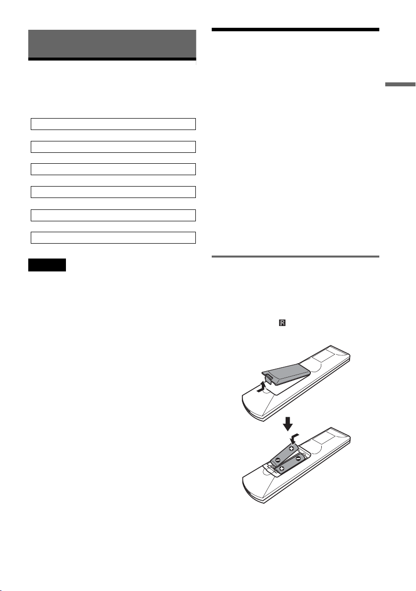
Inserting batteries into the remote
You can control the system using the supplied
remote. Insert two R6 (size AA) batteries by
matching the 3 and # ends on the batteries to the
markings inside the compartment.
Point the remote at (remote sensor) on the
centre unit when operating the system.
Hookups and Settings
,continued
5

Notes
• Do not leave the remote in an extremely hot or humid
place.
• Do not drop any foreign object into the remote casing,
particularly when replacing the batteries.
• Use the batteries correctly to avoid possible leakage
and corrosion. Do not touch the liquid with bare hands
should leakage occur. Observe the following:
– Do not use a new battery with an old battery, or
batteries of different manufacturers.
– Do not attempt to recharge the batteries.
– If you do not intend to use the remote for an extended
period of time, remove the batteries.
– If battery leakage occurs, wipe out any liquid inside
the battery compartment, and insert new batteries.
• Do not expose the remote sensors (marked on the
centre unit) to strong light, such as direct sunlight or
lighting apparatus. The system may not respond to the
remote.
About the code setting for operating other
component
You can operate not only the system but also other
connected components (TV, DVD recorder/
player, etc.) with the supplied remote (page 31).
Default settings are as follows:
TV: Sony TV
DVD: Sony DVD recorder
VIDEO: Sony VCR (VHS)
If you connect a component that is not in the
default setting list above (such as a DVD player,
etc.), you can operate them (Sony products only
except for the TV) with the supplied remote by
setting the appropriate code. For details, see
“Operating Other Components With the Supplied
Remote” on page 31.
6
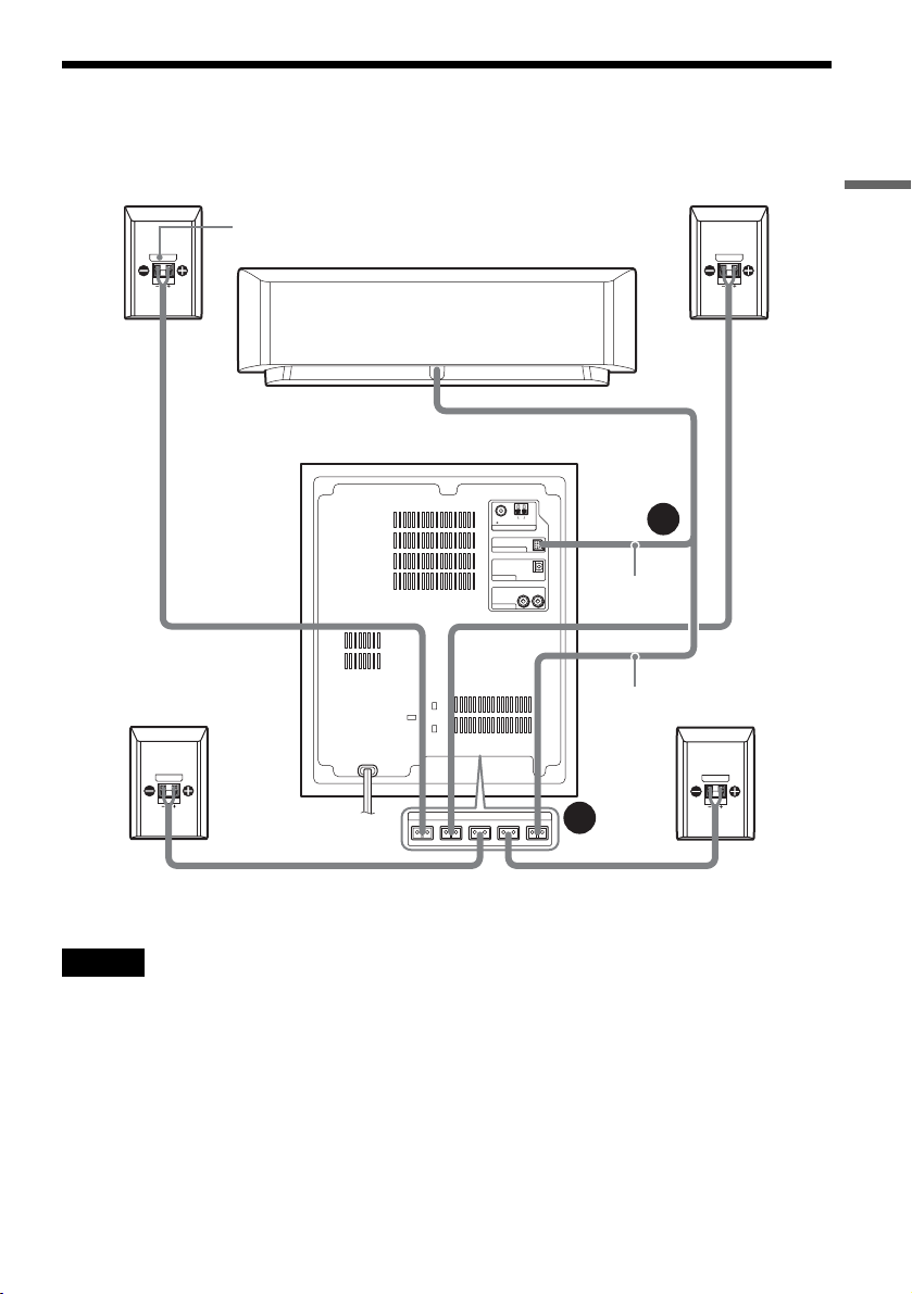
Step 2: Connecting the Speakers
Connect the speakers to the subwoofer using the supplied speaker cords as shown in A and B below.
Front speaker (R)
Surround speaker (R)
Colour label
Subwoofer
Centre unit
(The centre speaker is built in to
the centre unit.)
AM
FM
75 COAXIAL
AERIAL
SYSTEM CONTROL
DIGITAL IN OPTICAL
DVD
L
R
ANALOG IN
VIDEO
SPEAKERS
FRONT R FRONT L SURR R SURR L CENTER
to SYSTEM
CONTROL
System cord
Speaker cord
A
Front speaker (L)
B
Surround speaker (L)
Hookups and Settings
to SPEAKER jacks on the bottom side
Notes
• Do not set the speakers in an inclined position.
• Do not place the speakers in locations that are:
– Extremely hot or cold
– Dusty or dirty
– Very humid
– Subject to vibrations
– Subject to direct sunlight
• Do not connect any speakers other than those supplied
with this system.
• Use caution when placing the speakers and/or speaker
stands (not supplied) that are attached with the speakers
on a specially treated (waxed, oiled, polished, etc.)
floor, as staining or discoloration may result.
,continued
7
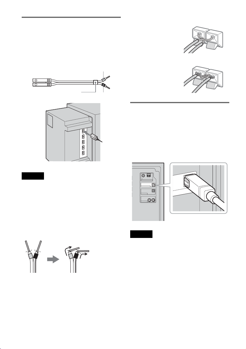
A Wiring the speakers
Connect the supplied speakers to the SPEAKER
jacks on the bottom side of the subwoofer using
the speaker cords.
Use the speaker cord whose tube is the same
colour as the jack label on the connecting speaker.
Example:
Too much insulation is
removed. Stripped cords are
touching each other.
Grey
(+)
(–)
Colour tube
(+)
(–)
Black
Notes
• Cover the floor with a cloth when connecting.
• Be sure to match the polarity of the speaker cord and
the terminal on the component; 3 to 3 (grey), # to #
(black). If reversed, the sound will lack bass and may
be distorted.
Notes on speaker cord treatment
• Do not insert the speaker cord insulation in the
speaker terminals. Bend the stripped cord at the
end of the insulation before connecting.
• To prevent short-circuiting of the speakers,
make sure the stripped speaker cord does not
touch the other stripped speaker cord or the
terminal.
Stripped cords are touching
the other speaker terminals.
B Connecting the subwoofer and
the centre unit
Connect the system cord of the centre unit to the
SYSTEM CONTROL jack of the subwoofer,
then, connect the speaker cord to the CENTER
SPEAKER jack. Insert the SYSTEM CONTROL
plug fully until it clicks.
to SYSTEM CONTROL
AM
FM
75 COAXIAL
AERIAL
SYSTEM CONTROL
DIGITAL IN OPTICAL
DVD
LR
ANALOG IN
VIDEO
Notes
• If the system cord is disconnected while the power is
on, the system enters standby mode (page 14).
• After connecting the speakers, centre unit, and the
mains leads, you can check for a speaker short-circuit
using the test tone (page 27). If the test tone is not
output, or is output from a speaker other than indicated
in the centre unit display, check the speaker
connection.
• Be sure to connect the system cord to the subwoofer’s
SYSTEM CONTROL jack properly oriented to avoid
damage to the jack or system cord.
TROL
N
8
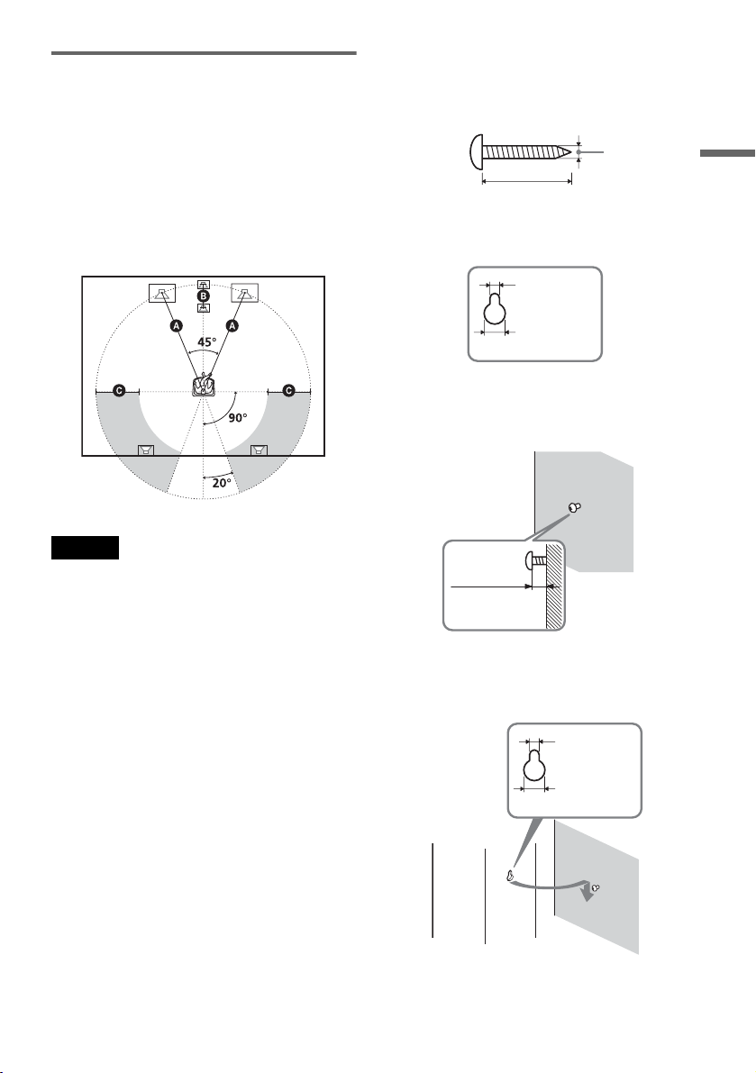
Positioning the speakers
For the best possible surround sound, all the
speakers other than the subwoofer should be the
same distance from the listening position (A).
However, this system allows you to place the
centre unit up to 1.6 m closer (B) and the
surround speakers up to 4.6 m closer (C) to the
listening position.
The front speakers can be placed from 1.0 to 7.0 m
(A) from the listening position.
Note
Do not place the centre unit and surround speakers
farther away from the listening position than the front
speakers.
To install the speakers on a wall
1 Prepare screws (not supplied) that are suitable
for the hole on the back of each speaker.
4mm
30mm
Hole on the back of the speaker
4.6mm
10mm
2 Fasten the screws to the wall.
The screws should protrude 5 to 7 mm.
5 to 7 mm
Hookups and Settings
Note on subwoofer placement
If the subwoofer is placed too close to a CRT TV
or projector, magnetic leakage may interfere with
the video signals and cause colour irregularity.
Should this happen, turn off the TV or the
projector, wait for 15 to 30 minutes, and then turn
it on again. If the problem persists, try the
following:
– Place the subwoofer at least 0.3 m away from the
TV or the projector.
– Remove any magnetic object near the subwoofer
(healthcare devices, toys, etc.). Magnetic latches
on TV stands may also cause the problem.
3 Hang the speakers on the screws.
Hole on the back of the speaker
4.6 mm
10 mm
,continued
9
Notes
• Use screws that are suitable for the wall material and
strength. As a plaster board wall is especially fragile,
attach the screws securely to a beam and fasten them to
the wall. Install the speakers on a vertical, flat wall
where reinforcement is applied.
• Contact a screw shop or installer regarding the wall
material or screws to be used.
• Sony is not responsible for accident or damage caused
by improper installation, insufficient wall strength or
improper screw installation, natural calamity, etc.
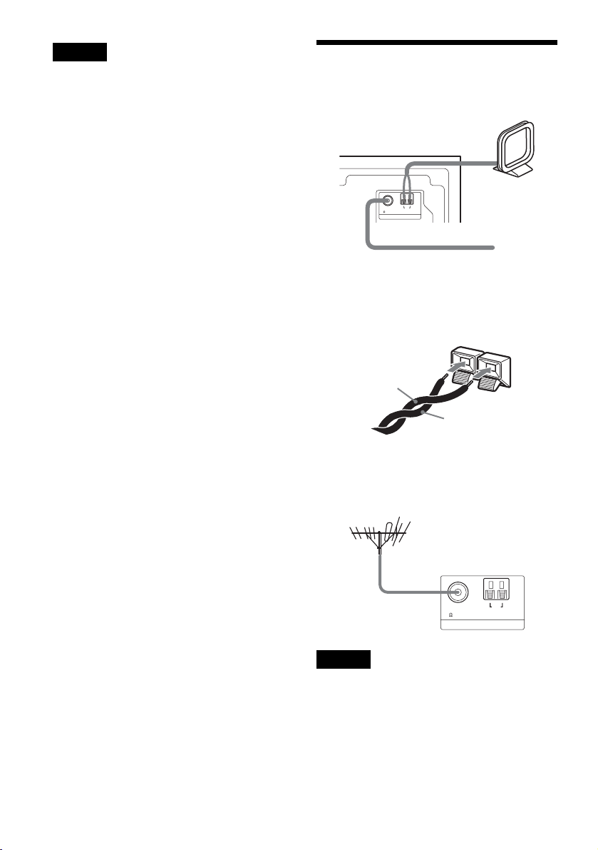
Step 3: Connecting the FM/ AM Aerials
Subwoofer
AM loop aerial
AM
FM
75 COAXIAL
AERIAL
FM wire aerial (supplied)
z Hints
• When connecting the AM loop aerial, cord (A) or cord
(B) can be connected to either terminal.
A
• If you have poor FM reception, use a 75-ohm coaxial
cable (not supplied) to connect the system to an
outdoor FM aerial (not supplied) as shown below.
Outdoor FM aerial
(not supplied)
(supplied)
B
10
Subwoofer
FM
75 COAXIAL
AM
AERIAL
Notes
• To prevent interference, keep the FM/AM aerial away
from the system and other components.
• Be sure to fully extend the FM wire aerial.
• After connecting the FM wire aerial, keep it as
horizontal as possible.
Step 4: Connecting the Other Components
Connect the other components (DVD recorder/player, “Play Station 2,” VCR, etc.) to the system.
See also the operating instructions supplied with the connected components.
To listen to the sound of other components through the system, see “Enjoying the Sound of the System”
(page 16).
Note
Disconnect the system and component mains leads from the mains when connecting them.
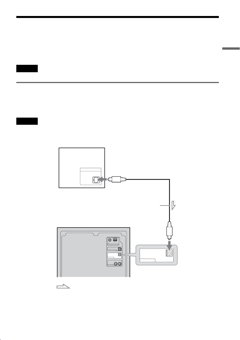
Connecting a DVD recorder/player or “Play Station 2”
Connect the DVD (DIGITAL IN OPTICAL) jack of the subwoofer to the DIGITAL OUT (OPTICAL)
jack of your DVD recorder/player or “Play Station 2” using the optical digital cord (supplied).
To listen to the connected component, press DVD (input select button) (page 16).
Note
You cannot input the video signal to this system. When you connect other components (DVD recorder/player, “Play
Station 2,” etc.), connect the video output jacks of the components to the video input jack of your TV.
DVD recorder/player or “Play Station 2”
Hookups and Settings
DIGITAL OUT
OPTICAL
to DIGITAL
OUT (OPTICAL)
Optical
digital cord
(supplied)
Subwoofer
AM
FM
75 COAXIAL
AERIAL
SYSTEM CONTROL
DIGITAL IN OPTICAL
DVD
ANALOG IN
VIDEO
L
R
DIGITAL IN OPTICAL
DVD
to DVD (DIGITAL IN
OPTICAL)
: Signal flow
z Hint
You can connect a satellite tuner with the optical digital out jack instead of a DVD player or recorder.
,continued
11

Setting for when using a Sony DVD recorder/player or “Play Station 2’
When connecting a Sony DVD recorder/player or “Play Station 2” as shown on the previous page,
perform the following settings on each component to fully enjoy the surround sound of the system. Other
settings may be necessary for other manufacture’s DVD recorder/player. For details, refer to the operating
instructions supplied with each component.
DVD recorder/player
1 Select “AUDIO SETUP” in the setup display.
“Play Station 2”
1 Select “AUDIO SETTING” in the setup
2 Set “AUDIO DRC” to “WIDE RANGE.”
3 Set “DIGITAL OUT” to “ON.”
4 Set “DOLBY DIGITAL” to “DOLBY
DIGITAL.”
5 Set “DTS’ to “ON.”
6 Set “Fs” to “48 kHz.”
“Play Station 2” is a trademark of Sony Computer Entertainment.
2 Select “AUDIO DIGITAL OUTPUT.”
3 Set “OPTICAL DIGITAL OUTPUT” to
4 Set “DOLBY DIGITAL” to “ON.”
5 Set “DTS’ to “ON.”
display.
“ON.”
12
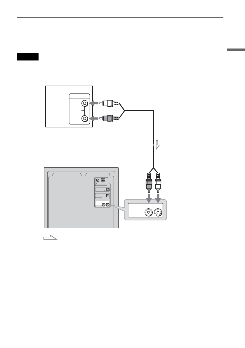
Connecting a VCR or TV
Connect the VIDEO (ANALOG IN L/R) jacks of the subwoofer to the AUDIO OUT (L/R) jacks of the
VCR or TV using the audio cord (not supplied).
To listen to the connected VCR or TV, press VIDEO (input select button) (page 16).
Note
You cannot input the video signal to this system. When you connect other components (VCR, TV, etc.), connect the
video output jacks of the components to the video input jack of your TV.
VCR or TV
to AUDIO OUT (L/R)
OUTPUT
L
AUDIO
R
Subwoofer
(white)
(red)
Audio cord
(not supplied)
Hookups and Settings
FM
75 COAXIAL
SYSTEM CONTROL
DIGITAL IN OPTICAL
DVD
ANALOG IN
VIDEO
AM
AERIAL
L
R
(red)
ANALOG IN
VIDEO
(white)
L
R
to VIDEO (ANALOG
IN L/R)
: Signal flow
z Hints
• If the VCR or TV outputs only monaural sound, use audio cords that distribute monaural sounds to the left/right
channels (not supplied). In this case, the surround effect may not be effective.
• If the connected VCR or TV is set for the surround sound, the system’s surround effect may not be audible. Set the
surround setting of the VCR or TV to off.
13
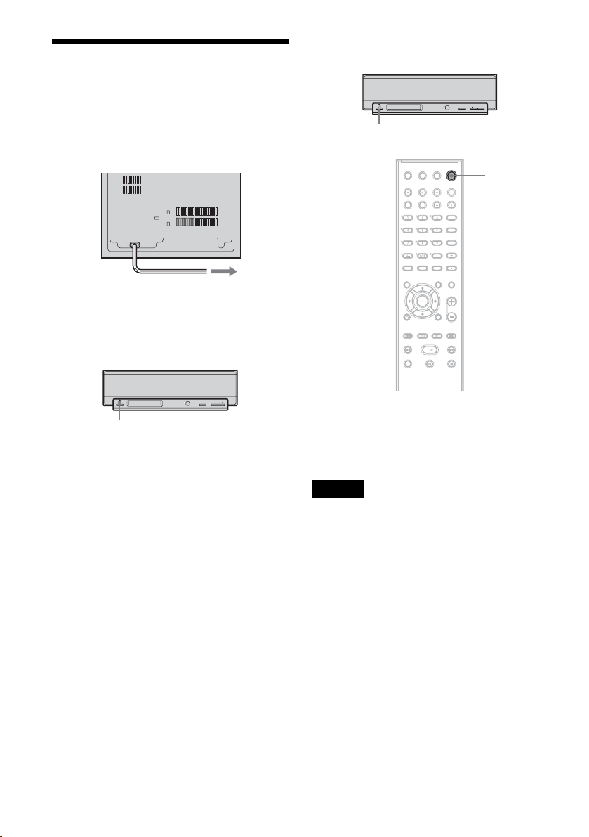
Step 5: Connecting the Mains Leads
Plug the subwoofer and TV mains leads (power
cords) into the mains.
To turn the system on and off
Centre unit
FUNCTION VOLUMEVOLUME
"/1
Subwoofer
to mains
Check that the "/1 indicator on the centre unit
lights up when the subwoofer mains lead is
connected.
Centre unit
FUNCTION VOLUMEVOLUME
"/1 indicator
After all connections are complete, follow the
steps of “Step 6: Basic Speaker Setup” (page 15).
"/1
Press [/1.
When you turn off the system, the system enters
standby mode and the [/1 indicator in the centre
unit display lights up in red.
Note
When you disconnect the mains lead in standby mode,
the [/1 indicator lights up for a while. This is not a
malfunction.
14
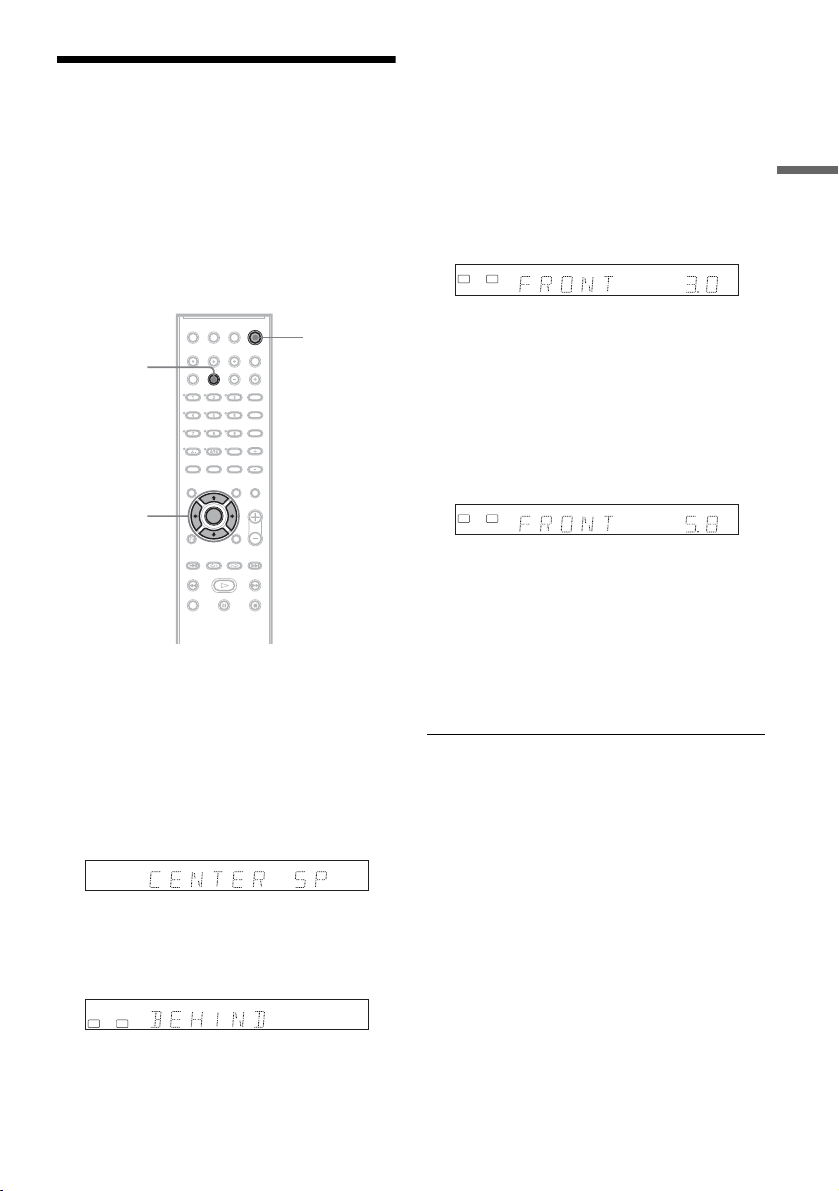
Step 6: Basic Speaker Setup
To fully enjoy the system’s sound, reflect the
current speaker positions in the system. Enter the
speaker distance from your listening position
using the AMP menu in the centre unit display.
For details about the AMP menu, see page 24;
about speaker placement, see page 9.
5 Press M/m to select the setting for the
surround speaker position.
If unsure about the position, see ““SURR SP”
(surround speaker)” on page 25.
6 Press < to return to the previous layer.
7 Press M/m to select “FRONT DIST” (front
speaker distance), and press ENTER or
,.
L R
m
Hookups and Settings
"/1
AMP MENU
</M/m/,,
ENTER
1 Press [/1 to turn on the system.
2 Press AMP MENU repeatedly until the AMP
menu (page 24) appears in the centre unit
display.
3 Press M/m to select “SP SETUP” (speaker
setup), and press ENTER or ,.
Example:
4 Press M/m to select “SURR SP” (surround
speaker), and press ENTER or ,.
SL SR
8 Press M/m to set the front speaker
distance from the listening position.
The display changes in 0.2 m increments,
from 1.0 to 7.0 m. Enter the shorter distance if
the two speaker distances differ.
Example: When entering 5.8 m for the front
left and right speakers.
L R
m
9 Press < to return to the previous layer.
10Repeat steps 7 to 9 to set “CEN DIST”
(centre speaker distance) and “SURR
DIST” (surround speaker distance).
11Press AMP MENU to turn off the AMP
menu.
To better adjust the speaker
You can change the speaker level, etc. See
“Speaker Level Settings (LEVEL)” (page 26).
To return to the previous layer
Press <.
To operate the connected component after
setting
Select the component (input source) by pressing
DVD, VIDEO, or TUNER/BAND after turning
off the AMP menu.
Basic hookups and settings are complete.
You are ready to start using the system.
15
 Loading...