

Page 1

4-415-789-91(2)
Home Theatre
System
Operating Instructions US
Manual de instrucciones ES
HT-M7/HT-M5/HT-M3
Page 2
WARNING
To reduce the risk of fire or electric
shock, do not expose this apparatus to
rain or moisture.
To reduce the risk of fire, do not cover the
ventilation opening of the appliance with
newspapers, tablecloths, curtains, etc.
Do not expose the appliance to naked flame sources
(for example, lighted candles).
Do not install the appliance in a confined space, such
as a bookcase or built-in cabinet.
To reduce the risk of fire or electric shock, do not
expose this apparatus to dripping or splashing, and
do not place objects filled with liquids, such as
vases, on the apparatus.
As the main plug is used to disconnect the unit from
the mains, connect the unit to an easily accessible
AC outlet. Should you notice an abnormality in the
unit, disconnect the main plug from the AC outlet
immediately.
Do not expose batteries or appliances with batteryinstalled to excessive heat, such as sunshine and fire.
The unit is not disconnected from the mains as long
as it is connected to the AC outlet, even if the unit
itself has been turned off.
This symbol is intended to alert
the user to the presence of the Hot
Surface that may be hot if it is
touched during the normal
operation.
For customers in the United
States
Owner’s Record
The model and serial numbers are located on the rear
of the unit. Record these numbers in the space
provided below. Refer to them whenever you call
upon your Sony dealer regarding this product.
Model No.
Serial No.
This symbol is intended to alert
the user to the presence of
uninsulated “dangerous voltage”
within the product’s enclosure
that may be of sufficient
magnitude to constitute a risk of
electric shock to persons.
This symbol is intended to alert
the user to the presence of
important operating and
maintenance (servicing)
instructions in the literature
accompanying the appliance.
Important Safety Instructions
1) Read these instructions.
2) Keep these instructions.
3) Heed all warnings.
4) Follow all instructions.
5) Do not use this apparatus near water.
6) Clean only with dry cloth.
7) Do not block any ventilation openings. Install in
accordance with the manufacturer’s instructions.
8) Do not install near any heat sources such as
radiators, heat registers, stoves, or other
apparatus (including amplifiers) that produce
heat.
9) Do not defeat the safety purpose of the polarized
or grounding-type plug. A polarized plug has
two blades with one wider than the other. A
grounding type plug has two blades and a third
grounding prong. The wide blade or the third
prong are provided for your safety. If the
provided plug does not fit into your outlet,
consult an electrician for replacement of the
obsolete outlet.
10)Protect the power cord from being walked on or
pinched particularly at plugs, convenience
receptacles, and the point where they exit from
the apparatus.
11)Only use attachments/accessories specified by
the manufacturer.
12)Use only with the cart, stand, tripod, bracket, or
table specified by the manufacturer, or sold with
the apparatus. When a cart is used, use caution
when moving the cart/apparatus combination to
avoid injury from tip-over.
US
2
Page 3

13)Unplug this apparatus during lightning storms or
when unused for long periods of time.
14)Refer all servicing to qualified service personnel.
Servicing is required when the apparatus has
been damaged in any way, such as power-supply
cord or plug is damaged, liquid has been spilled
or objects have fallen into the apparatus, the
apparatus has been exposed to rain or moisture,
does not operate normally, or has been dropped.
The following FCC statement
applies only to the version of
this model manufactured for
sale in the U.S.A. Other
versions may not comply with
FCC technical regulations.
NOTE:
This equipment has been tested and found to comply
with the limits for a Class B digital device, pursuant
to Part 15 of the FCC Rules. These limits are
designed to provide reasonable protection against
harmful interference in a residential installation.
This equipment generates, uses and can radiate radio
frequency energy and, if not installed and used in
accordance with the instructions, may cause harmful
interference to radio communications. However,
there is no guarantee that interference will not occur
in a particular installation. If this equipment does
cause harmful interference to radio or television
reception, which can be determined by turning the
equipment off and on, the user is encouraged to try
to correct the interference by one or more of the
following measures:
– Reorient or relocate the receiving antenna.
– Increase the separation between the equipment
and receiver.
– Connect the equipment into an outlet on a circuit
different from that to which the receiver is
connected.
– Consult the dealer or an experienced radio/TV
technician for help.
About This Manual
• The instructions in this manual are for models
HT-M7, HT-M5 and HT-M3. In this manual, the
HT-M7 is used for illustration purposes unless
stated otherwise.
• The instructions in this manual describe the
operation of the receiver with the supplied remote
control. You can also use the control buttons or
knobs on the receiver if they have the same or
similar names as those on the remote control.
The HT-M7 consists of:
• Receiver STR-KM7
• Speaker system
– Front speaker SS-MSP7M (2)
– Center speaker SS-CNP7M (1)
– Surround speaker SS-MSP3M (2)
– Surround back speaker SS-SRP7M (2)
– Subwoofer SS-WP7M (2)
The HT-M5 consists of:
• Receiver STR-KM5
• Speaker system
– Front speaker SS-MSP7M (2)
– Center speaker SS-CNP7M (1)
– Surround speaker SS-SRP7M (2)
– Subwoofer SS-WP7M (2)
The HT-M3 consists of:
• Receiver STR-KM3
• Speaker system
– Front speaker SS-MSP3M (2)
– Center speaker SS-CNP7M (1)
– Surround speaker SS-SRP7M (2)
– Subwoofer SS-WP3M (2)
CAUTION
You are cautioned that any changes or modifications
not expressly approved in this manual could void
your authority to operate this equipment.
Properly shielded and grounded cables and
connectors must be used for connection to host
computers and/or peripherals in order to meet FCC
emission limits.
US
3
Page 4

On Copyrights
This receiver incorporates Dolby* Digital and Pro
Logic Surround and the DTS** Digital Surround
System.
* Manufactured under license from Dolby
Laboratories. Dolby, Pro Logic, and the doubleD symbol are trademarks of Dolby Laboratories.
** Manufactured under license under U.S. Patent
Nos: 5,956,674; 5,974,380; 6,226,616; 6,487,535
& other U.S. and worldwide patents issued &
pending. DTS, the Symbol, & DTS and the
Symbol together are registered trademarks &
DTS Digital Surround | 96/24 is a trademark of
DTS, Inc. Product includes software. © DTS,
Inc. All Rights Reserved.
This receiver incorporates High-Definition
Multimedia Interface (HDMI
TM
) technology.
The terms HDMI and HDMI High-Definition
Multimedia Interface, and the HDMI Logo are
trademarks or registered trademarks of HDMI
Licensing LLC in the United States and other
countries.
“x.v.Color (x.v.Colour)” and “x.v.Color
(x.v.Colour)” logo are trademarks of Sony
Corporation.
“BRAVIA” is a trademark of Sony Corporation.
“PlayStation” is a registered trademark of Sony
Computer Entertainment Inc.
MPEG Layer-3 audio coding technology and patents
licensed from Fraunhofer IIS and Thomson.
“WALKMAN” is a registered trademark of Sony
Corporation.
MICROVAULT is a trademark of Sony
Corporation.
Windows Media is either a registered trademark or
trademark of Microsoft Corporation in the United
States and/or other countries.
This product is protected by certain intellectual
property rights of Microsoft Corporation. Use or
distribution of such technology outside of this
product is prohibited without a license from
Microsoft or an authorized Microsoft subsidiary.
US
4
Page 5

Table of Contents
About This Manual ....................................... 3
Supplied accessories ..................................... 6
Description and location of parts .................. 7
Getting started ............................................. 15
Connections
1: Installing the speakers............................. 16
2: Connecting the speakers ......................... 18
3: Connecting the TV.................................. 22
4a: Connecting the video equipment........... 23
4b: Connecting the audio equipment .......... 28
5: Connecting the antennas (aerials)........... 29
Preparing the Receiver
Setting the voltage selector ......................... 30
Connecting the AC power cord
(mains lead)............................................ 30
Initializing the receiver ............................... 30
Selecting surround speaker position ...........31
Adjusting the speaker levels and balance
(TEST TONE)........................................ 31
Basic Operations
Playing an input source equipment............. 32
Playing a USB device
(Except for South Africa and Argentina
models)................................................... 34
Viewing information on the display
panel....................................................... 36
Recording using the receiver....................... 37
Enjoying Surround Sound
Selecting the sound field .............................41
Resetting sound fields to the default
settings.................................................... 42
“BRAVIA” Sync Features
What is “BRAVIA” Sync?........................... 42
Preparing for the “BRAVIA” Sync..............43
Playing back equipment with one-touch
operation (One-Touch Play)................... 44
Enjoying the TV sound from the speakers
connected to the receiver
(System Audio Control) .........................44
Turning off the receiver with the TV
(System Power-Off)................................45
Enjoying optimum sound field for the
selected scene (Scene Select) .................45
Advanced Operations
Switching between digital and analog
audio (INPUT MODE)...........................46
Using the setting menu ................................46
Additional Information
Precautions ..................................................52
Troubleshooting...........................................53
Specifications ..............................................59
Index............................................................63
Tuner Operations
Listening to FM/AM radio.......................... 38
Presetting FM/AM radio stations................ 39
US
5
Page 6
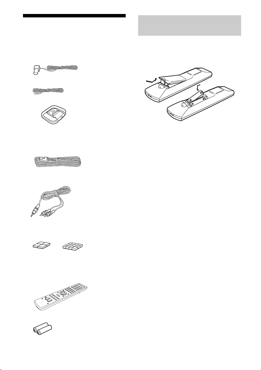
Supplied accessories
• Operating Instructions (this manual)
• Quick Setup Guide (1)
• FM wire antenna (aerial) (1)
– USA and Mexico models only
– Other models
• AM loop antenna (aerial) (1)
Inserting batteries into the
remote control
Insert two R6 (size AA) batteries (supplied) by
matching 3 and # on the batteries to the
diagram inside the battery compartment of the
remote control.
• Speaker cords
–HT-M7 (
6, red/white/blue/grey/purple × 2
– HT-M5 (4, red/white/purple × 2)
–HT-M3 (2, red/white)
• Audio cord with stereo mini-plug (Australia
model only) (1)
• Foot pads
– Subwoofers (Big) (8)
– Speakers (Small) (12)
• Remote control (1)
– RM-AAU136 (South Africa and
Argentina models only)
– RM-AAU135 (Other models)
Notes
)
• Do not leave the remote control in an extremely hot
or humid place.
• Do not use a new battery with old ones.
• Do not mix manganese batteries and other kinds of
batteries.
• Do not expose the remote control sensor to direct
sunlight or lighting apparatuses. Doing so may
cause a malfunction.
• If you do not intend to use the remote control for an
extended period of time, remove the batteries to
avoid possible damage from battery leakage and
corrosion.
• When the receiver no longer responds to the
remote control, replace all the batteries with new
ones.
• R6 (size AA) batteries (2)
US
6
Page 7
sw
Description and location of parts
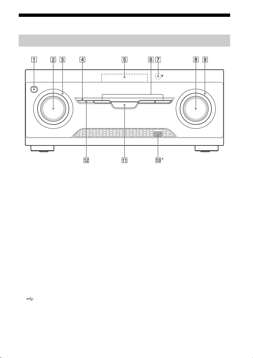
Front panel
* Except for South Africa and Argentina models.
A ?/1 (on/standby) (page 30, 42)
B INPUT SELECTOR (page 32, 33, 35, 37,
38, 39, 40, 46, 54)
C INPUT SELECTOR indicator
Flashes when you change the input source.
D M-TURBO indicator
Lights up when M-TURBO is activated.
E Display panel (page 8)
F MOVIE, MUSIC, GAMING (page 41)
G Remote control sensor
Receives signals from remote control.
H MASTER VOLUME (page 32, 33, 35)
I MASTER VOLUME indicator
Flashes when you adjust the volume.
J (USB) port (page 29)
K M-TURBO
Turns the M-TURBO function on or off.
M-TURBO function reinforces the bass and
creates a more powerful sound.
L SURROUND SPEAKER (page 31)
US
7
Page 8
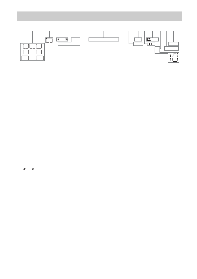
Indicators on the display panel
q
q
1324 6897q
5
s
a
;
LFE
HDMI
COAX OPT LPCM
LC
SL S
SB
SBL
SW
R
SR
SBR
A Playback channel indicator
The letters (L, C, R, etc.) indicate the channels
being played back. Based on the speaker
settings, the box around the letter(s) vary to
show how the receiver downmixes the source
sound.
L
R
C
SL
SR
S
Front Left
Front Right
Center (monaural)
Surround Left
Surround Right
Surround (monaural or the
surround equipment obtained
by Pro Logic processing)
SBL*
SBR*
SB*
Surround Back Left
Surround Back Right
Surround Back (the surround
back equipment obtained by
6.1 channel decoding)
B SW
Lights up when the audio signal is output from
the SUBWOOFER jack.
C
LFE
Lights up when the disc being played back
contains an LFE (Low Frequency Effect)
channel and the LFE channel signal is actually
being reproduced.
DTS 96/24
D Input indicator
Lights up to indicate the current input.
HDMI
– The INPUT MODE is set to “AUTO”, and
when the receiver recognizes the equipment
connected via an HDMI IN jack (page 46).
– The TV input detected Audio Return Channel
(ARC) signals.
COAX
The INPUT MODE is set to “AUTO” or
“COAX”, and when the source signal is a digital
signal through the COAXIAL jack (page 46).
OPT
The INPUT MODE is set to “AUTO” or
“OPT”, and when the source signal is a digital
signal through the OPTICAL jack (page 46).
E DTS indicator
Lights up the respective indicator when the
receiver is decoding the corresponding DTS
format signals.
DTS
DTS 96/24
Note
When playing a DTS format disc, make sure that
you have completed the digital connections and
that INPUT MODE is not set to “ANALOG”
(page 46).
F LPCM
Lights up when the receiver is decoding the
Linear PCM signals.
G USB**
Lights up when a USB device is being played.
USB
PL II
D
DTS
DTS 96 kHz/24 bit
SLEEP
D.RANGEST
US
8
Page 9

H D
Lights up when the receiver is decoding Dolby
Digital signals.
Note
When playing a Dolby Digital format disc, make
sure that you have completed the digital
connections and that INPUT MODE is not set to
“ANALOG” (page 46).
I Dolby Pro Logic indicator
Lights up the respective indicator when the
receiver performs Dolby Pro Logic processing.
This matrix surround decoding technology can
enhance input signals.
PL
PL II
Dolby Pro Logic
Dolby Pro Logic II
J Tuning indicator
Lights up when the receiver tunes to a radio
station.
ST
Stereo broadcast
Preset station number (The number will change
according to the preset station you select.)
K D.RANGE
Lights up when dynamic range compression is
activated (page 49).
L SLEEP
Lights up when the Sleep Timer is activated
(page 14).
* HT-M7 only.
** Except for South Africa and Argentina models.
US
9
Page 10
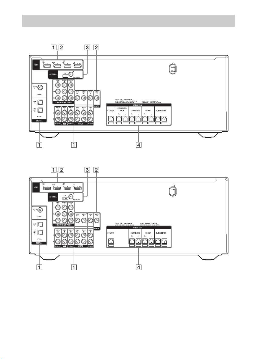
Rear panel
HT-M7
HT-M5
10
US
Page 11
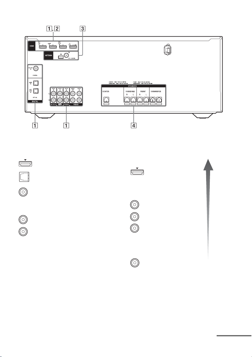
HT-M3
A Audio signal section
DIGITAL INPUT/OUTPUT jacks (page 22, 25,
26, 27)
HDMI IN/OUT
OPTICAL IN
COAXIAL IN
ANALOG INPUT/OUTPUT jacks (page 22, 26,
28)
White (L)
Red (R)
AUDIO IN/OUT
B Video signal section*
The image quality depends on the connecting jack.
DIGITAL INPUT/OUTPUT
jacks (page 22, 25)
HDMI IN/OUT
COMPONENT VIDEO
INPUT/OUTPUT jacks** (page
22, 26)
Green
(Y)
Blue
(P
Red
(P
B)
R)
B, PR IN/OUT
Y, P
COMPOSITE VIDEO INPUT/
OUTPUT jacks** (page 22, 26,
28)
Yellow
VIDEO IN/OUT
* You must connect the HDMI TV OUT or
MONITOR OUT (HT-M7/HT-M5 only) jack to
your TV to watch the selected input image (page
22).
** HT-M7/HT-M5 only.
High
quality
image
continued
11
US
Page 12

C ANTENNA section (page 29)
FM ANTENNA jack
AM ANTENNA terminal
D SPEAKERS section (page 18, 19,
20)
12
US
Page 13
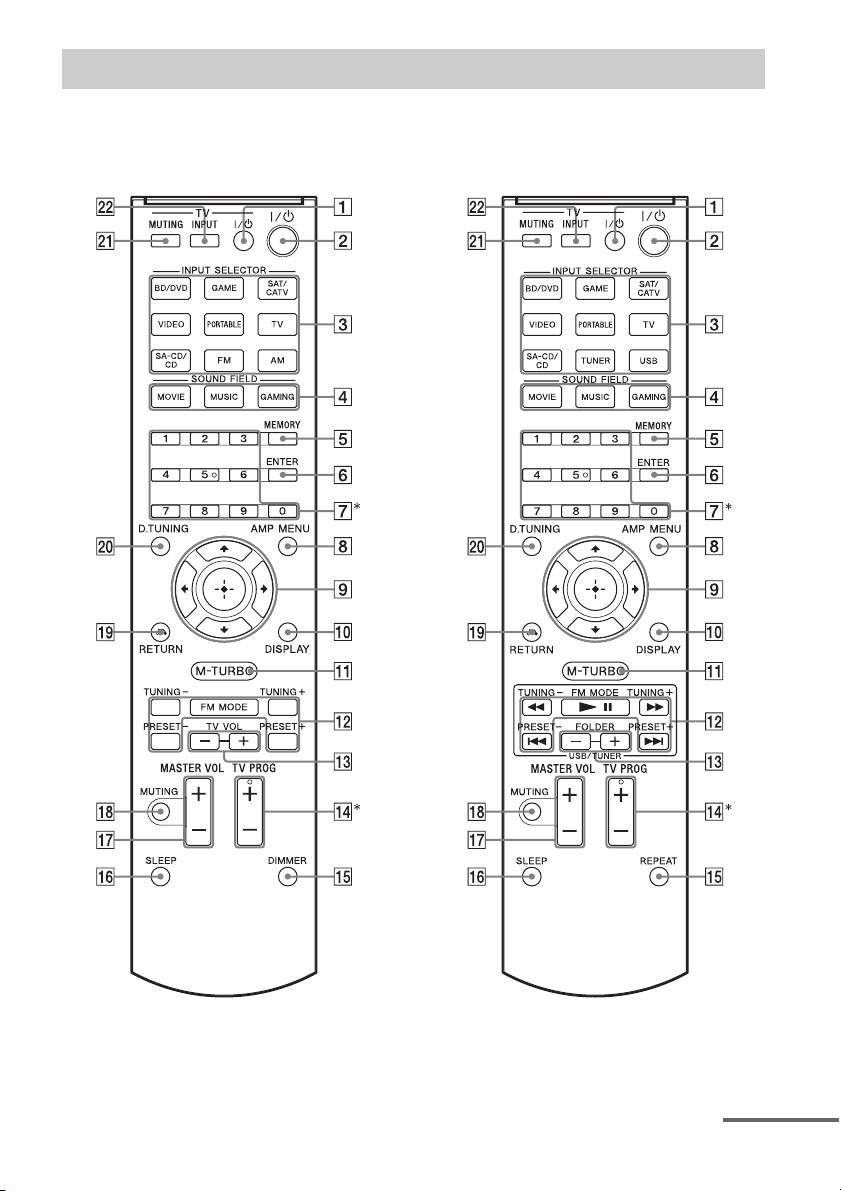
Remote control
Use the supplied remote control to operate this receiver and Sony TV.
• RM-AAU136 (South Africa and
Argentina models only)
• RM-AAU135 (Other models)
* The 5 and TV PROG + buttons have tactile dots. Use the tactile dots as references when operating the
receiver.
continued
13
US
Page 14

To control the receiver
B ?/1 (on/standby)
Turns the receiver on or sets it to standby mode.
Saving the power in standby mode
When “CTRL.HDMI” is set to “CTRL OFF”
(page 48).
C Input buttons
Selects the equipment you want to use. When
you press any of the input buttons, the receiver
turns on.
D MOVIE, MUSIC, GAMING (page 41)
E MEMORY
Stores a station during tuner operation.
F ENTER
Enters the selections.
G Numeric buttons
Presets or tunes to the preset stations (page 39).
H AMP MENU
Displays the menu to operate the receiver.
I
J DISPLAY
K M-TURBO
L m/M, NX, ./>
M FOLDER +/–
O REPEAT
V/v/B/b
,
Press V/v/B /b to select the settings, then press
to enter/confirm the selection.
Views information on the display panel.
Turns the M-TURBO function on or off.
M-TURBO function reinforces the bass and
creates a more powerful sound.
(RM-AAU135 only)
Operates the USB device: Backward/forward,
play/pause, skip operation.
TUNING +/–
Scans a station.
FM MODE
Selects the FM reception mode (monaural or
stereo).
PRESET +/–
Selects preset stations.
(RM-AAU135 only)
Selects a folder of the USB device.
(RM-AAU135 only)
Plays a track or a folder repeatedly of the USB
device.
DIMMER
(RM-AAU136 only)
Adjusts the brightness of the display panel.
P SLEEP
Sets the receiver to turn off automatically at a
specified time.
The display changes cyclically as follows.
0-30-00 t 1-00-00 t 1-30-00 t 2-00-00 t
OFF
When Sleep Timer is being used, “SLEEP”
indicator lights up on the display panel.
Tip
To check the remaining time before the receiver
turns off, press SLEEP. The remaining time
appears on the display panel. If you press
SLEEP again, the Sleep Timer will be canceled.
Q MASTER VOL +/–
Adjusts the volume level of all speakers at the
same time.
R MUTING
Turns off the sound temporarily.
Press MUTING again to restore the sound.
S RETURN O
Returns to the previous menu.
T D.TUNING
Enters direct tuning mode.
To control a Sony TV
A TV ?/1 (on/standby)
Turns the TV on or off.
M TV VOL +/–
(RM-AAU136 only)
Adjusts the TV volume.
N TV PROG +/–
Scans for the preset TV channels.
U TV MUTING
Activates the TV’s muting function.
V TV INPUT
Selects the input signal (TV or video).
Note
The above explanation is intended to serve as
examples.
14
US
Page 15
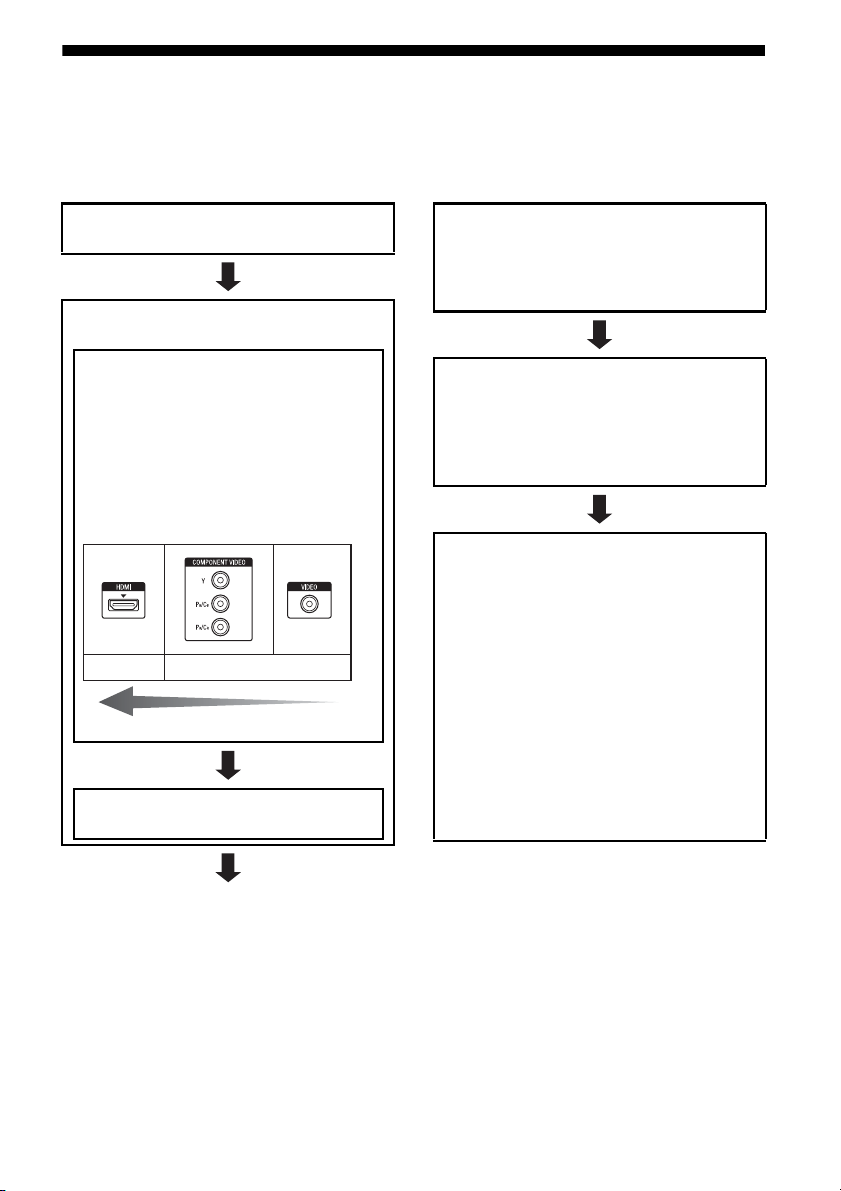
Getting started
You can enjoy your audio/video equipment connected to the receiver by following the simple steps
below.
Before connecting cords, be sure to disconnect the AC power cord (mains lead).
Installing and connecting the
speakers (page 16, 18)
Checking the connection
appropriate for your equipment
Connecting the TV and video
equipment (page 22, 23)
The image quality depends on the connecting
jack. See the illustration below. Select the
connection according to the jacks on your
equipment.
We recommend that you connect your video
equipment via HDMI connection if they have
HDMI jacks.
Digital
High quality image
Analog
Connecting the audio equipment
(page 28)
Preparing the receiver
See “Setting the voltage selector” (page 30),
“Connecting the AC power cord (mains lead)”
(page 30) and “Initializing the receiver” (page
30).
Setting the speakers
Select the surround speaker position (page 31),
then check the speaker connection using
“T. TONE” in LEVEL menu (page 31). If the
sound is not output correctly, check the speaker
connection.
Setting the audio output settings on
the connected equipment
To output multi channel digital audio, check the
digital audio output setting on the connected
equipment.
For a Sony Blu-ray Disc player, check that “Audio
(HDMI)”, “Dolby Digital”, and “DTS” are set to
“Auto”, “Dolby Digital” and “DTS” respectively
(as of September 2011).
For a PlayStation 3, check that “BD/DVD Audio
Output Format (HDMI)” and “BD Audio Output
Format (Optical Digital)” are set to “Bitstream”
(with system software version 3.70).
For details, refer to the operation instructions
supplied with the connected equipment.
15
US
Page 16
Connections
1: Installing the speakers
HT-M7
This receiver allows you to use a 7 channel
speaker with 2 subwoofer system.
– HT-M5/HT-M3
HT-M5/HT-M3
This receiver allows you to use a 5 channel
speaker with 2 subwoofer system.
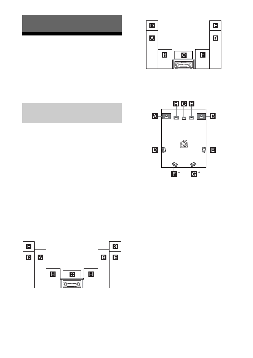
Example of speaker system
configuration
You can enjoy different sound effects from the
system by placing the speakers as shown
below.
AFront speaker (left)
BFront speaker (right)
CCenter speaker
DSurround speaker (left)
ESurround speaker (right)
FSurround back speaker (left)
GSurround back speaker (right)
HSubwoofer
Installing all the speakers in
front position
– HT-M7
Installing the surround/
surround back speakers in rear
position
* HT-M7 only.
Notes
• Do not install the speakers on a wall.
• (HT-M7 only)
We recommend that you place the surround back
speakers on a speaker stand (not supplied).
• (HT-M5/HT-M3 only)
We recommend that you place the surround
speakers on a speaker stand (not supplied).
• For details about installing the speakers, please
refer to the supplied Quick Setup Guide.
16
US
Page 17
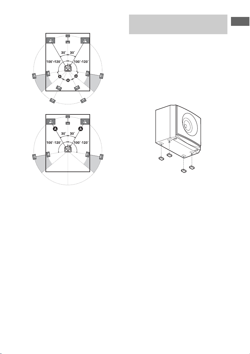
Tips
• All the angles A should be the same.
–HT-M7 only
– HT-M5/HT-M3 only
• Since the subwoofer does not emit highly
directional signals, you can place it wherever you
want.
Installing the speakers on a flat
surface
Attach the supplied foot pads to the bottom of
the speakers and subwoofers to prevent
vibration or movement.
HT-M7:
Center speaker, surround back speakers,
subwoofers
HT-M5/HT-M3:
Center speaker, surround speakers,
subwoofers
Note
Attach the small foot pads to the center speaker,
surround speakers and surround back speakers and
the big foot pads to the subwoofers.
Connections
17
US
Page 18

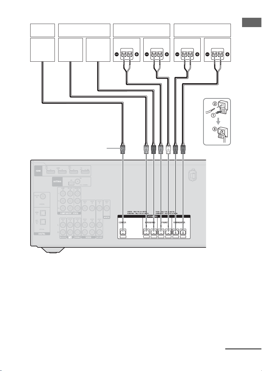
2: Connecting the speakers
Before connecting cords, be sure to disconnect the AC power cord (mains lead).
HT-M7
Center
speaker
Surround back speaker
Connector
Right
Left
A
Right Left Right Left
Surround speaker Front speaker Subwoofer
A Speaker cord (supplied)
US
18
AA
Page 19
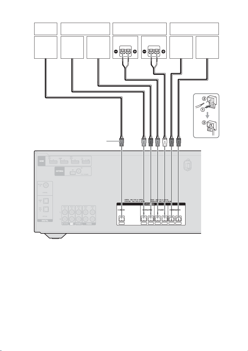
HT-M5
speaker
Center
Surround speaker Front speaker Subwoofer
Right
Left
Right Left
AA
Connector
Connections
A Speaker cord (supplied)
continued
19
US
Page 20
HT-M3
Center
speaker
Surround speaker Front speaker Subwoofer
Right
Left
Right Left
A
Connector
A Speaker cord (supplied)
US
20
Page 21

Note on speaker cords
The connector of the speaker cords are colorcoded based on the speaker type. When
connecting a speaker cord, be sure to match
the colored connector to the speaker terminal
on the receiver.
Connector Speaker terminal
Purple SUBWOOFER
White FRONT L
Red FRONT R
Blue SURROUND L
Grey SURROUND R
Brown SURROUND BACK L
Tan SURROUND BACK R*
Green CENTER
* HT-M7 only.
*
To connect the speakers
correctly
Check the speaker type by referring to the
speaker label* on the rear panel of the
speakers.
Character on
speaker label
L Front left
R Front right
SL Surround left
SR Surround right
SBL
** Surround back left
SBR
** Surround back right
* The center speaker and subwoofers do not have
any character on the speaker label. For details on
the speaker type, see page 3.
** HT-M7 only.
Speaker type
Connections
21
US
Page 22
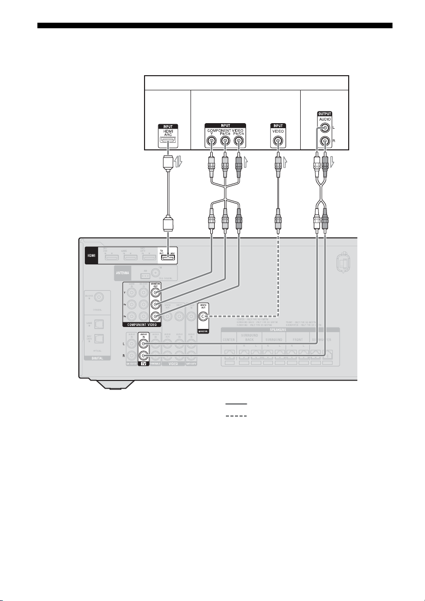
3: Connecting the TV
Before connecting cords, be sure to disconnect the AC power cord (mains lead).
TV
Audio/Video
signals
Video signals
1)
or
Audio signals
2)
A
3)
BC
A HDMI cable (not supplied)
Sony recommends that you use an HDMIauthorized cable or Sony HDMI cable.
B Component video cord (not supplied)
C Video cord (not supplied)
D Audio cord (not supplied)
4)
D
Recommended connection
Alternative connection
22
US
Page 23

1)
HT-M7/HT-M5 only.
2)
If your TV is compatible with the Audio Return
Channel (ARC) function, connect A to enjoy the
TV broadcast in multi channel surround sound
from the speakers connected to the receiver.
Be sure to turn off the TV’s volume or activate the
TV’s muting function.
3)
If you connect the receiver to the Audio Return
Channel (ARC) compatible TV, the TV sound will
output from the speakers connected to the receiver
via the HDMI TV OUT jack.
Be sure to set the “CTRL.HDMI” to “CTRL ON”
in the HDMI menu (page 51).
4)
If your TV is not compatible with the Audio
Return Channel (ARC) function, connect D to
output the sound of the TV from the speakers
connected to the receiver.
Be sure to turn off the TV’s volume or activate the
TV’s muting function.
Notes
• Connect a TV monitor or a projector to the HDMI
TV OUT or MONITOR OUT (HT-M7/HT-M5
only) jack on the receiver. You may not be able to
record even if you connect recording equipment.
• Depending on the status of the connection between
the TV and the antenna (aerial), the image on the
TV screen may be distorted. If this is the case,
place the antenna (aerial) farther away from the
receiver.
Tip
When you connect the audio output jack of the TV
to the TV IN jacks of the receiver to output the TV
sound from the speakers connected to the receiver,
set the sound output jack of the TV to “Fixed” if it
can be switched between either “Fixed” or
“Variable”.
To listen to the sound from the
TV
If your TV does not support System Audio
Control function, set the “AUDIO.OUT” to
“TV+AMP” in the HDMI menu (page 51).
4a: Connecting the video equipment
Using HDMI connection
High-Definition Multimedia Interface
(HDMI) is an interface which transmits video
and audio signals in digital format.
By connecting Sony “BRAVIA” Synccompatible equipment using HDMI cables,
operations can be simplified. See ““BRAVIA”
Sync Features” (page 42).
HDMI features
• A digital audio signals transmitted by HDMI
can be output from the speakers connected to
the receiver. This signal supports Dolby
Digital, DTS, and Linear PCM. For details,
see “Digital audio formats supported by the
receiver” (page 41).
• The receiver can receive Multi Channel
Linear PCM (up to 8 channels) with a
sampling frequency of 192 kHz or less with
an HDMI connection.
• This receiver supports Deep Color (Deep
Colour), “x.v.Color (x.v.Colour)” and 3D
transmission.
• To enjoy 3D images, connect 3D-compatible
TV and video equipment (Blu-ray Disc
player, Blu-ray Disc recorder, PlayStation 3,
etc.) to the receiver using High Speed HDMI
cables, put on 3D glasses, and then play back
a 3D-compatible content.
Notes on HDMI connections
• DSD signals of Super Audio CD are not
input and output.
• Depending on the TV or the video
equipment, 3D images may not be
displayed.
• Refer to the operating instructions of each
connected equipment for details.
Connections
23
US
Page 24

When connecting cords
• Before connecting cords, be sure to
disconnect the AC power cord (mains lead).
• It is not necessary to connect all the cords.
Connect according to the availability of
jacks on the connected equipment.
• Use a High Speed HDMI cable. If you use a
Standard HDMI cable, 1080p, Deep Color
(Deep Colour) or 3D images may not be
displayed properly.
• We do not recommend using an HDMI-DVI
conversion cable. When you connect an
HDMI-DVI conversion cable to a DVI-D
equipment, the sound and/or the image may
be lost.
• When connecting optical digital cords, insert
the plugs straight until they click into place.
• Do not bend or tie optical digital cords.
Tip
All the digital audio jacks are compatible with
32 kHz, 44.1 kHz, 48 kHz, and 96 kHz sampling
frequencies.
24
US
Page 25
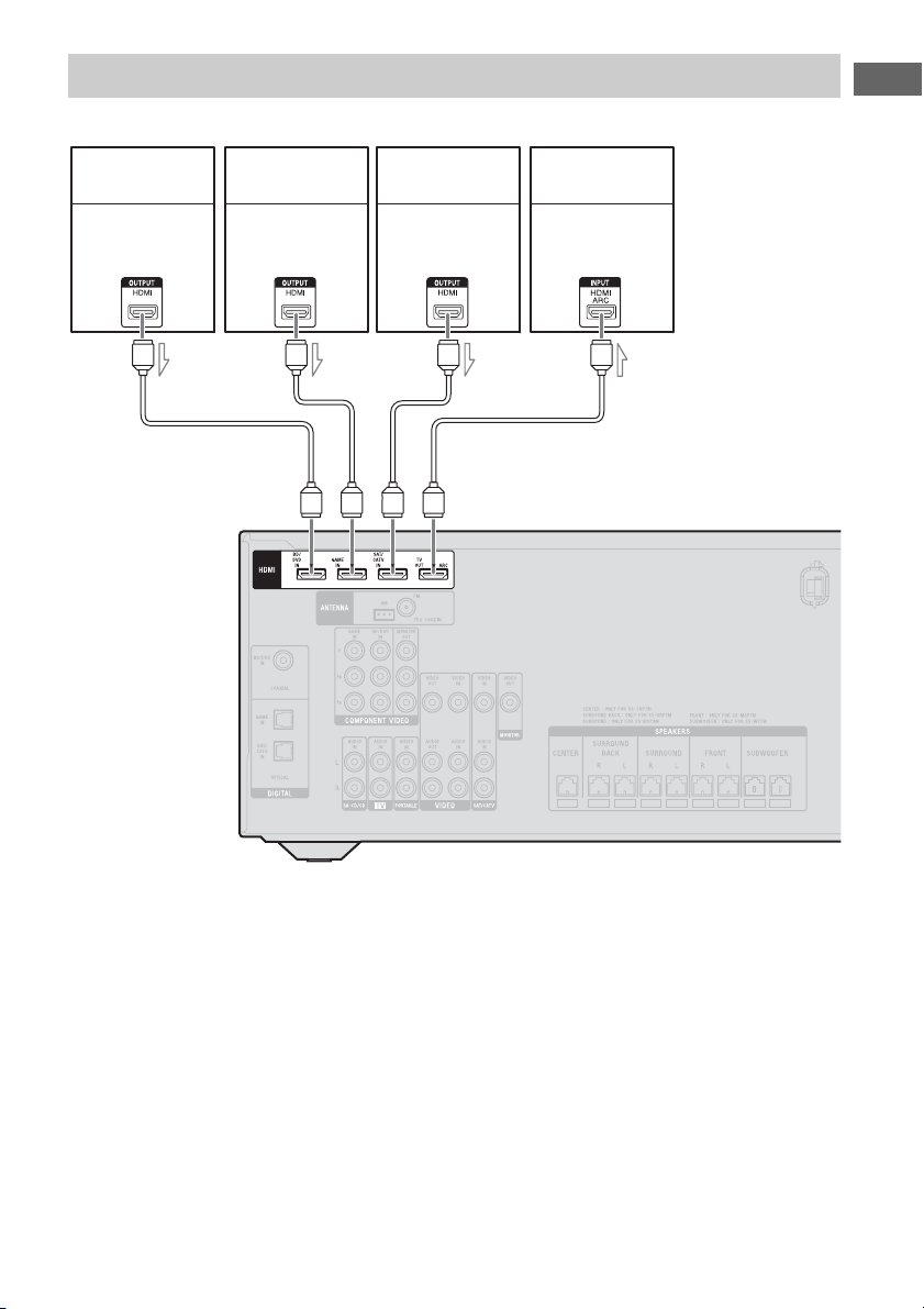
Connecting equipment with HDMI jacks
If your equipment does not have an HDMI jack, see page 26.
Connections
Blu-ray Disc player,
DVD player
Audio/video
signals
A
PlayStation 3
Audio/video
signals
Satellite tuner,
cable TV tuner
Audio/video
signals
TV, etc.
Audio/video
signals
AA A
A HDMI cable (not supplied)
Sony recommends that you use an HDMIauthorized cable or Sony HDMI cable.
25
US
Page 26
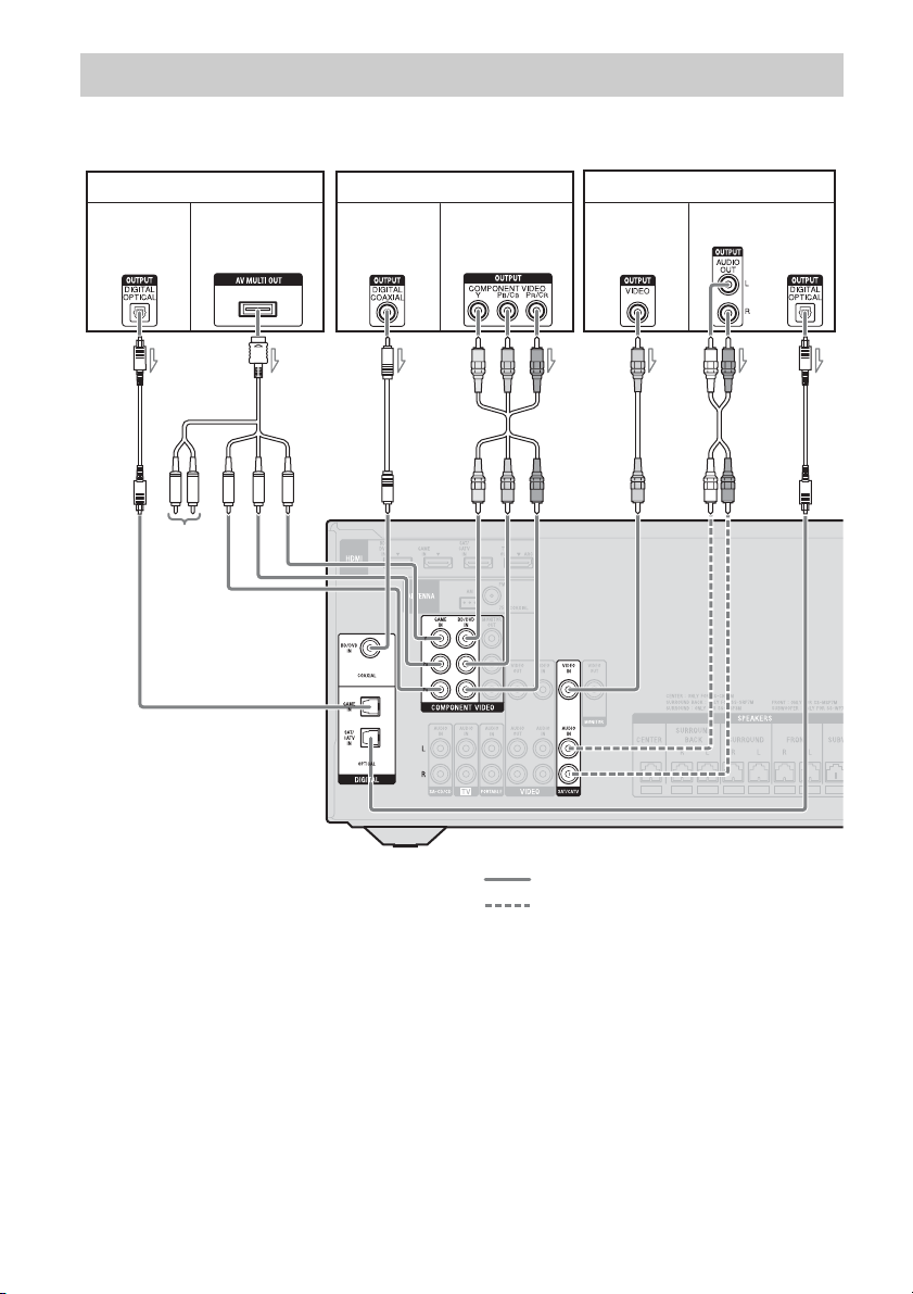
Connecting equipment with jacks other than HDMI jacks
HT-M7/HT-M5
PlayStation 3
Video signalsAudio signals
AC
Not used
BF
Blu-ray Disc player, DVD player
Video signalsAudio signals
DAE
Satellite tuner, cable TV tuner
Video signals Audio signals
or
A Optical digital cord (not supplied)
B Component AV cable (not supplied)
C Coaxial digital cord (not supplied)
D Component video cord (not supplied)
E Video cord (not supplied)
F Audio cord (not supplied)
US
26
Recommended connection
Alternative connection
Page 27
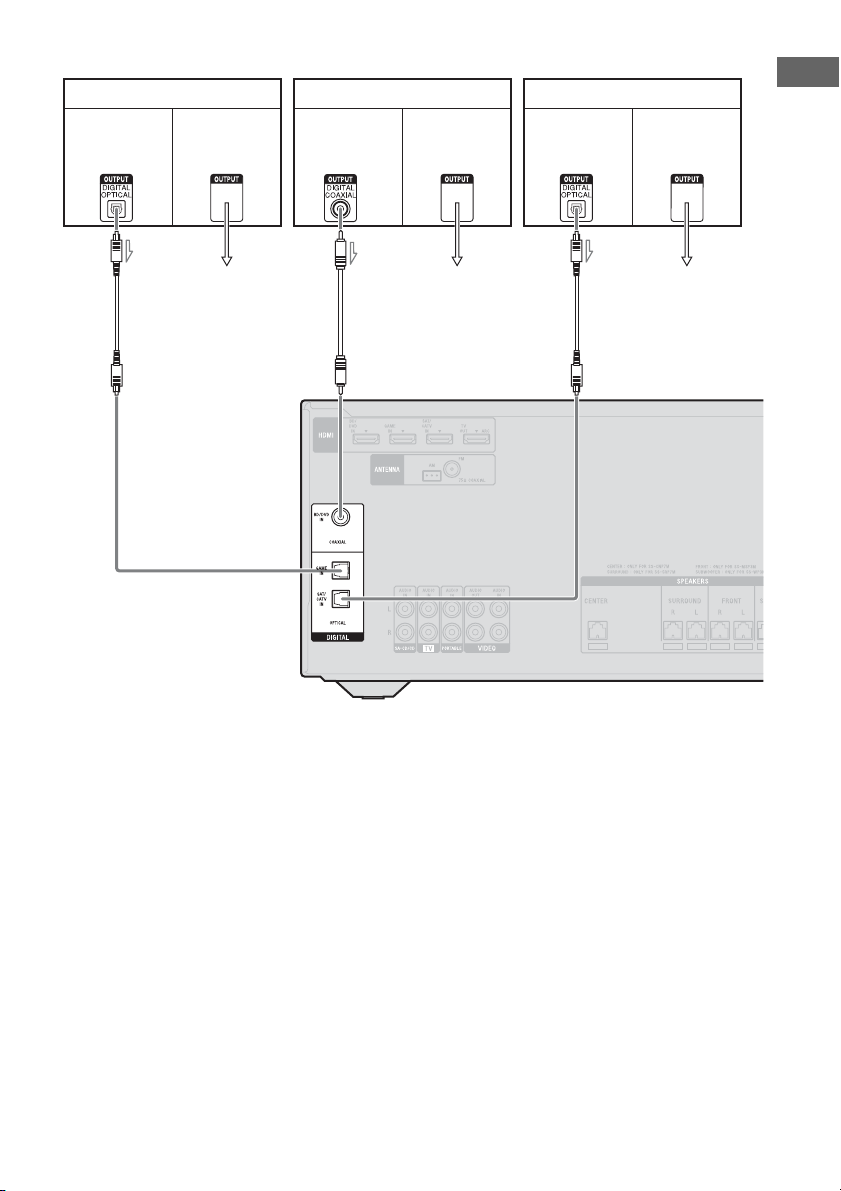
HT-M3
PlayStation 3
Video signalsAudio signals
To the VIDEO IN
of the TV.
Blu-ray Disc player, DVD player
Video signalsAudio signals
BAA
To the VIDEO IN
of the TV.
Satellite tuner, cable TV tuner
Audio signals Video signals
To the VIDEO IN
of the TV.
Connections
A Optical digital cord (not supplied)
B Coaxial digital cord (not supplied)
27
US
Page 28
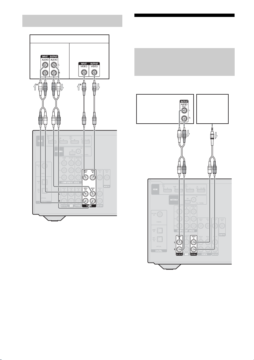
Connecting a VCR, DVD recorder
4b: Connecting the audio
A
VCR, DVD recorder
Audio signals
Video signals
**
B
equipment
Connecting a Super Audio CD
player, CD player, portable
audio
Before connecting cords, be sure to disconnect the
AC power cord (mains lead).
Super Audio
CD player,
CD player
AB
Portable
audio
A Audio cord (not supplied)
B Video cord (not supplied)
* If you want to record, you must make this
connection (page 37).
** HT-M7/HT-M5 only.
Note
(HT-M3 only)
Be sure to connect the video output of the VCR or
DVD recorder to the TV, so that the image is
displayed on the TV. For details, refer to the
operating instructions of the connecting equipment.
US
28
A Audio cord (not supplied)
B Audio cord with stereo mini-plug
(supplied for Australia model only)
Page 29
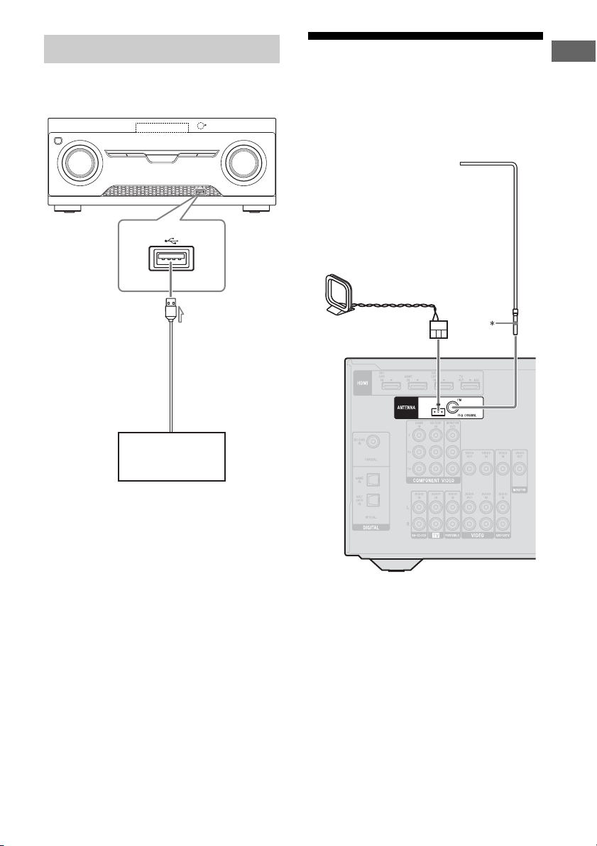
Connecting a USB device
(Except for South Africa and
Argentina models)
A
USB device
5: Connecting the antennas (aerials)
Before connecting antennas (aerials), be sure
to disconnect the AC power cord (mains lead).
FM wire antenna (aerial)
(supplied)
AM loop antenna (aerial)
(supplied)
Connections
A USB cable (not supplied)
* The shape of the connector varies depending on
the area of this receiver.
Notes
• To prevent noise pickup, keep the AM loop
antenna (aerial) away from the receiver and other
equipment.
• Be sure to fully extend the FM wire antenna
(aerial).
• After connecting the FM wire antenna (aerial),
keep it as horizontal as possible.
29
US
Page 30
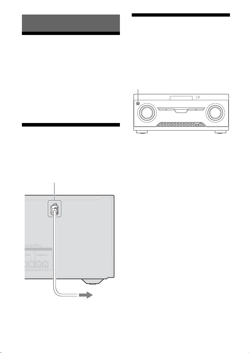
Preparing the Receiver
Initializing the receiver
Setting the voltage selector
If your receiver has a voltage selector on the
rear panel, check that the voltage selector is set
to the local power supply voltage. If not, use a
screwdriver to set the selector to the correct
position before connecting the AC power cord
to a wall outlet.
Depending on the area, the VOLTAGE
SELECTOR may differ.
Connecting the AC power cord (mains lead)
Connect the AC power cord (mains lead) to a
wall outlet.
AC power cord (mains lead)
Before using the receiver for the first time,
initialize the receiver by performing the
following procedure. This procedure can also
be used to revert back to the factory default
settings.
Be sure to use the button on the receiver to
perform this operation.
?/1
1 Press ?/1 to turn off the
receiver.
2 Hold down ?/1 for 5 seconds.
The “CLEARING” appears on the
display panel for a while, then changes to
“CLEARED”.
Changes or adjustments made to the
settings are now reset to the defaults.
30
To the wall outlet
US
Page 31

Selecting surround
Adjusting the speaker
speaker position
Select the surround speaker position according
to the speaker configuration.
AMP
MENU
,
V/v/B/b
1 Press AMP MENU.
2 Press V/v repeatedly to select
“SPKR”, then press or b.
3 Press V/v repeatedly to select
“SUR SPK”, then press or b.
4 Press V/v repeatedly to select
the speaker position you want.
• FRONT: If you install all the speakers
in front position, select “FRONT”.
• REAR: If you install the surround/
surround back speakers at rear position,
select “REAR” to enjoy multi channel
surround sound.
Tip
You can also press SURROUND SPEAKER
repeatedly on the receiver to select the surround
speaker position.
levels and balance
(TEST TONE)
You can adjust the speaker levels and balance
while listening to the test tone from your
seating position.
Input
buttons
AMP
MENU
,
V/v/B/b
MASTER
VOL +/–
Preparing the Receiver
1 Press AMP MENU.
2 Press V/v repeatedly to select
“LEVEL”, then press or b.
3 Press V/v repeatedly to select
“T. TONE”, then press or b.
continued
31
US
Page 32

4 Press V/v repeatedly to select
“AUTO xxx
The test tone is output from each speaker
in sequence.
* xxx represent a speaker channel.
*”.
5 Adjust the speaker levels and
balance.
Use the LEVEL menu (page 49) to adjust
the speakers to have the same sounding
test tone level for each speaker.
Tips
•
To adjust the level of all speakers at the same
time, press MASTER VOL +/–. You can also
use MASTER VOLUME on the receiver.
• The adjusted value are shown on the display
panel during adjustment.
6 Exit test tone.
Press any input buttons or select “OFF”
under step 4.
When a test tone is not output
from the speakers
• The speaker cords may not be connected
securely.
• The speaker cords may have the short-circuit
problem.
• The MASTER VOLUME may has set to
“VOL MIN”.
Basic Operations
Playing an input source equipment
Input
buttons
MOVIE,
MUSIC,
GAMING
AMP
MENU
,
V/v/B/b
MASTER
VOL +/–
MUTING
32
1
Press the input button which
corresponds to the equipment
you want.
You can also use INPUT SELECTOR on
the receiver.
The selected input appears on the display
panel.
2 Turn on the equipment and
start playback.
US
Page 33

3 Press MASTER VOL +/– to
adjust the volume.
You can also use MASTER VOLUME on
the receiver.
4 Press MOVIE, MUSIC or
GAMING to enjoy the surround
sound.
For details, see page 41.
To activate the muting function
Press MUTING on the remote control.
The muting function will be canceled when
you do the following.
• Press the button again.
• Increase the volume.
• Turn off the receiver.
To avoid damaging your
speakers
Before you turn off the receiver, be sure to turn
down the volume level.
Naming inputs
You can enter a name of up to 8 characters for
inputs (except TUNER) to appear on the
display panel.
It is more recognizable having the equipment
named on the display than the jacks.
1 Press the corresponding input
button which you want to
create an index name.
You can also use INPUT SELECTOR on
the receiver.
2 Press AMP MENU.
3 Press V/v repeatedly to select
“SYSTEM”, then press or b.
4 Press V/v repeatedly to select
“NAME IN”, then press or b.
The cursor flashes and you can enter a
character.
5 Press V/v to select a character,
then press B/b to move the
input position backward and
forward.
Basic Operations
Tips
•You can select the character type as follows
by pressing V/v.
Alphabet (upper case) t Numbers t
Symbols
•To enter a blank space, press b without
selecting a character.
If you made a mistake
Press B/b until the character you want to
change flashes, then press V/v to select
the correct character.
6 Press .
The name you entered is registered.
33
US
Page 34

Playing a USB device
(Except for South Africa and
Argentina models)
You can enjoy music from the USB device by
connecting it to the (USB) port on the
receiver.
For details on connecting a USB device, see
“Connecting a USB device” (page 29).
The music file formats that can be played back
by this receiver are as follows:
File format Extensions
MP3 (MPEG-1 Audio
Layer III)
AAC* “.m4a”, “.3gp”, “.mp4”
WMA9 Standard* “.wma”
* The receiver does not play files encoded with
DRM.
Compatible USB devices
You can use the following Sony USB devices
on this receiver.
Verified Sony USB device
Product name Model name
Walkman
®
“.mp3”
NWZ-S754 / S755
NWZ-E453 / E454 / E455
NWZ-E353 / E354 / E355
NWZ-B133 / B135 / B133F /
B135F
NWZ-B142 / B143 / B142F /
B143F
NWD-E023F / E025F
NWZ-E435F / E436F / E438F
NWZ-E343 / E344 / E345
NWZ-S636F / S638F / S639F
NWZ-S736F / S738F / S739F
NWZ-A726 / A728 / A729 /
A726B / A728B
NWZ-A826 / A828 / A829
NWZ-W202
Product name Model name
NWZ-X1050 / X1060
NWZ-S744 / S745
NWZ-E443 / E444 / E445
NWZ-S543 / S544 / S545
NWZ-A844 / A845 / A846 /
A847
NWZ-W252 / W253
NWZ-B152 / B153 / B152F /
B153F
MICROVAULT USM1GL / 2GL / 4GL / 8GL /
16GL
USM1GLX / 2GLX / 4GLX /
8GLX / 16GLX
Notes
• The receiver is unable to read data in NTFS format.
• The receiver is unable to read data other than that
saved in the first partition of a hard disk drive.
• Operation of models not listed here is not
guaranteed.
• Operation may not always be ensured even when
using these USB devices.
• Some of these USB devices may not be available
for purchase in certain areas.
• When formatting the above models, be sure to
format using the model itself or the dedicated
formatting software for that model.
• When connecting a USB device to the receiver, be
sure to connect after the display “Creating Library”
or “Creating Database” on the USB device has
disappeared.
34
US
Page 35

Operating the USB device
USB
MOVIE,
MUSIC,
GAMING
NX
./>
MASTER
VOL +/–
m/M
FOLDER
+/–
REPEAT
1 Press USB.
You can also use INPUT SELECTOR on
the receiver.
When the USB device is connected,
“USB” indicator appears on the display
panel.
2 Press NX to start playback.
3 Press MASTER VOL +/– to
adjust the volume.
You can also use MASTER VOLUME on
the receiver.
4 Press MOVIE, MUSIC or
GAMING to enjoy the surround
sound.
For details, see page 41.
Other operations
Press Operation
NX Starts/pauses play.
m/M Fast reverses or forwards.
./> Goes to the previous/next file.
FOLDER +/– Goes to the previous/next folder.
REPEAT Enters repeat mode.
• RPT. OFF/RPT. ONE/
RPT. ALL/RPT. FLD
Notes on the USB device
• Do not remove the USB device during
operation. To avoid data corruption or
damage to the USB device, turn the receiver
off when removing the USB device.
• When USB cable connection is necessary,
connect the USB cable supplied with the
USB device to be connected. Refer to the
operating instructions supplied with the
USB device to be connected for details on
the operation method.
• Do not connect the receiver and the USB
device through a USB hub.
• When the USB device is connected,
“READING” appears.
• It may take about 10 seconds before
“READING” appears depending on the type
of USB device connected.
• When the USB device is connected, the
receiver reads all the files on the USB
device. If there are many folders or files on
the USB device, it may take a long time to
finish reading the USB device.
• The receiver can recognize up to
– 100 folders (including “ROOT” folder).
– 100 audio files for each folder.
– 8 folder levels (tree structure of files,
including “ROOT” folder).
The maximum number of audio files and
folders may vary depending on the file and
folder structure.
Do not save other types of files or
unnecessary folders on a USB device.
Basic Operations
continued
35
US
Page 36

• Compatibility with all encoding/writing
softwares, recording devices, and recording
media cannot be guaranteed. Incompatible
USB device may produce noise or
interrupted audio or may not play at all.
• Some time may be needed to start playback
when:
– the folder structure is complex.
– the memory capacity is excessive.
• This receiver does not necessarily support
all the functions provided in a connected
USB device.
• The playback order for the receiver may
differ from the playback order of the
connected USB device.
• Folders that have no audio files are skipped.
• When playing a very long track, some
operations may cause playback delay.
USB message list
Message and explanation
READING
The receiver is recognizing and reading information
of the USB device.
DEVICE ERROR
The memory of the USB device could not be
recognized (page 34).
NO SUPPORT
An unsupported USB device is connected, an
unknown device is connected, or the
USB device is connected through a USB hub
(page 34).
NO.DEVICE
No USB device is connected or the connected USB
device is not recognized.
NO TRACK
No track was found.
Viewing information on the display panel
The display panel provides various
information of the receiver status such as
sound field.
Input
buttons
AMP
MENU
DISPLAY
1 Press the corresponding input
button which you want to check
the information.
2 Press DISPLAY repeatedly.
Each time you press the button, the
display changes cyclically as follows:
Index name of the input* t Selected
input t Sound field currently applied t
Volume level t Stream info**
When listening to FM and AM radio
Preset station name* t Frequency t
Sound field currently applied t Volume
level
* Index name appears only when you have
assigned one to the input or preset station
(page 33, 40). Index name does not appear
when only blank spaces have been entered,
or it is the same as the input name.
**Stream information may not be displayed.
36
US
Page 37

Note
Character or marks may not be displayed for some
languages.
Recording using the receiver
• (HT-M3 only)
– You can only record audio signals using this
receiver.
– Audio input signals via HDMI IN and DIGITAL
IN jacks cannot be recorded.
You can record from an audio/video
equipment using the receiver. Refer to the
operating instructions supplied with your
recording equipment.
1 Prepare the source for playing.
Press the input button to select the source.
You can also use INPUT SELECTOR on
the receiver.
Example 1 (audio recording):
Press SA-CD/CD.
Example 2 (video recording
HT-M5 only):
Press SAT/CATV.
– HT-M7/
2 Prepare the recording
equipment.
Insert a blank video tape, etc. into the
recording equipment (connected to
VIDEO OUT jacks).
3 Start recording on the
recording equipment, then start
the playback equipment.
Notes
• Some sources contain copyright protection to
prevent recording. In this case, you may not be able
to record from the source.
• While the source is being recorded, the auto
standby function of the receiver may start up and
interrupt the recording. In this case, set the
“AUTO.STBY” to “STBY OFF” (page 52).
• (HT-M7/HT-M5 only)
Audio input signals via HDMI IN, DIGITAL IN
and COMPONENT VIDEO IN jacks cannot be
recorded.
Basic Operations
37
US
Page 38

Tuner Operations
Listening to FM/AM radio
You can listen to FM and AM broadcasts
through the built-in tuner. Before operation,
make sure you have connected the FM and
AM antennas (aerials) to the receiver (page
29).
Tip
The tuning scale for direct tuning is shown below.
Area FM AM
USA 100 kHz 10 kHz
Latin America, Argentina
and Mexico
Australia, South Africa,
Middle East, India, Thailand,
Singapore and Europe
* The AM tuning scale can be changed (page 39).
1)
TUNER
/
2)
FM
50 kHz 10 kHz*
50 kHz 9 kHz
2)
AM
Tuning to a station
automatically (Automatic
Tuning)
1 Press TUNER repeatedly (or
press FM or AM) to select the
FM or AM band.
You can also use INPUT SELECTOR on
the receiver.
2 Press TUNING + or TUNING –.
TUNING + scans from lower to higher
frequency stations and TUNING – for
*
scanning higher to lower.
The receiver stops scanning whenever a
station is received.
In case of poor FM stereo
reception
If the FM stereo reception is poor and “ST”
flashes on the display panel, select monaural
audio to lessen the sound distortion.
Press FM MODE repeatedly to select
“MONO”.
To return to stereo mode, press FM MODE
repeatedly to select “STEREO”.
Tuning to a station directly
(Direct Tuning)
Numeric
buttons
D.TUNING
,
V/v/B/b
FM MODE
1)
RM-AAU135 only.
2)
RM-AAU136 only.
US
38
ENTER
AMP
MENU
TUNING
+/–
You can enter the frequency of a station
directly by using the numeric buttons.
1 Press TUNER repeatedly (or
press FM or AM) to select the
FM or AM band.
You can also use INPUT SELECTOR on
the receiver.
2 Press D.TUNING.
Page 39

3 Press the numeric buttons to
enter the frequency.
Example 1: FM 102.50 MHz
Select 1 b 0 b 2 b 5 (b 0*)
Example 2: AM 1,350 kHz
Select 1 b 3 b 5 b 0
* You do need to press 0 for USA model.
Tip
Adjust the direction of the AM loop antenna
(aerial) for optimum reception upon tuning to
an AM station.
Note
All AM preset stations will be erased when you
change the tuning scale.
Presetting FM/AM radio stations
You can store up to 30 FM and 30 AM stations
as your favorite stations as preset stations.
4 Press ENTER.
If you cannot tune to a station
“–––.––MHz” or “––––kHz” appears and
then the display panel returns to the current
frequency.
Make sure you have entered the right
frequency. Try repeating steps 2 to 4. If you
still cannot tune to a station, the frequency
may not be in use in your area.
Changing the AM tuning scale
(USA, Latin America, Argentina
and Mexico models only)
You can change the AM tuning scale to either
9 kHz or 10 kHz.
1 Press TUNER repeatedly (or
press AM) to select AM.
2 Press AMP MENU.
3 Press V/v repeatedly to select
“TUNER”, then press or b.
4 Press V/v repeatedly to select
“AM STEP”, then press or b.
TUNER1)/
2)
FM
Numeric
buttons
,
V/v/B/b
PRESET
+/–
1)
RM-AAU135 only.
2)
RM-AAU136 only.
2)
AM
MEMORY
ENTER
AMP
MENU
1 Press TUNER repeatedly (or
press FM or AM) to select the
FM or AM band.
You can also use INPUT SELECTOR on
the receiver.
Tuner Operations
5 Press V/v repeatedly to select
the AM tuning scale you want.
2 Tune to the station that you
want to preset using Automatic
Tuning (page 38) or Direct
Tuning (page 38).
continued
39
US
Page 40

3 Press MEMORY.
4 Press the numeric buttons to
select a preset number.
You can also press PRESET + or
PRESET – to select a preset number.
5 Press ENTER.
The station is stored as the selected preset
number.
6 Repeat steps 1 to 5 to store
another station.
Tuning to preset stations
1 Press TUNER repeatedly (or
press FM or AM) to select the
FM or AM band.
2 Press PRESET + or PRESET –
repeatedly to select the station.
Each time you press the button, you can
select a preset station as follows:
4 Press V/v repeatedly to select
“TUNER”, then press or b.
5 Press V/v repeatedly to select
“NAME IN”, then press or b.
The cursor flashes and you can enter a
character.
6 Press V/v to select a character,
then press B/b to move the
input position backward and
forward.
You can enter up to 8 characters to name
the station.
Tips
•You can select the character type as follows
by pressing V/v.
Alphabet (upper case) t Numbers t
Symbols
•To enter a blank space, press b without
selecting a character.
If you made a mistake
Press B/b until the character you want to
change flashes, then press V/v to select
the correct character.
You can also press the numeric buttons to
enter the preset station. To tune to the
selection, press ENTER.
Naming preset stations
1 Press TUNER repeatedly (or
press FM or AM) to select the
FM or AM band.
You can also use INPUT SELECTOR on
the receiver.
2 Tune to the preset station you
want to create an index name
for (page 40).
3 Press AMP MENU.
US
40
7 Press .
The name you entered is registered.
Page 41

Enjoying Surround Sound
Selecting the sound field
This receiver can create multi channel
surround sound. You can select one of the
optimized sound fields from the receiver’s
pre-programmed sound fields.
MOVIE,
MUSIC,
GAMING
Press MOVIE, MUSIC or GAMING to
select the sound field you want.
Note
Before selecting the sound field, be s ure to s ele ct t he
surround speaker position according to the speaker
configuration. For details, see “Selecting surround
speaker position” (page 31).
x MOVIE A (Movie A)
Optimizes sound output from all speakers for
movie playback.
x MOVIE B (Movie B)
Reproduces a movie effect sound.
x MUSIC (Music)
Reproduces music sound with multi channel
output.
x GAMING (Gaming)
Reproduces the sound processing of video
games for better gaming experience.
Notes on sound fields
• The sound fields for music and movie do not
work for signals with a sampling frequency
of more than 48 kHz.
• The effects provided by the virtual speakers
may cause increased noise in the playback
signal.
• When listening with sound fields that
employ the virtual speakers, you will not be
able to hear any sound coming directly from
the surround speakers.
Tip
You can identify the encoding format of DVD
software, etc., by looking at the logo on the package.
To turn off the surround effect
Press MOVIE repeatedly to select
“MOVIE A”.
Enjoying Surround Sound
Digital audio formats supported by the receiver
Digital audio formats that this receiver can decode depend on digital audio output jacks of the
connected equipment. This receiver supports the following audio formats.
Audio format
Dolby Digital 5.1 aa
DTS 5.1 aa
DTS 96/24 5.1 aa
Multi Channel Linear PCM* 7.1 × a
* Audio signals are output in another format if the playback equipment does not correspond to the format. For
details, refer to the operating instructions of the playback equipment.
Maximum number of
channels
Connection between the playback
equipment and the receiver
COAXIAL/OPTICAL HDMI
41
US
Page 42

Resetting sound fields to the default settings
Be sure to use the buttons on the receiver to
perform this operation.
?/1
MUSIC
1 Press ?/1 to turn off the
receiver.
“BRAVIA” Sync Features
What is “BRAVIA” Sync?
The “BRAVIA” Sync function allows
communication between Sony products such
as TV, Blu-ray Disc/DVD player, AV
amplifier, etc. that supports the Control for
HDMI function.
By connecting Sony equipment that is
compatible with the “BRAVIA” Sync with an
HDMI cable (not supplied), operation is
simplified as follows:
• One-Touch Play (page 44)
• System Audio Control (page 44)
• System Power-Off (page 45)
• Scene Select (page 45)
2 While holding down MUSIC,
press ?/1.
“S.F. CLEAR” appears on the display
panel and all sound fields are reset to their
default setting.
Control for HDMI is a mutual control function
standard used by HDMI CEC (Consumer
Electronics Control) for HDMI (HighDefinition Multimedia Interface).
We recommend that you connect the receiver
to products featuring “BRAVIA” Sync.
Note
Depending on the connected equipment, the Control
for HDMI function may not work. Refer to the
operating instructions of the equipment.
42
US
Page 43

Preparing for the “BRAVIA” Sync
The receiver is compatible with the “Control
for HDMI-Easy Setting” function.
• If your TV is compatible with the “Control
for HDMI-Easy Setting” function, you can
set the Control for HDMI function of the
receiver and playback equipment
automatically by setting the Control for
HDMI function on your TV (page 43).
• If your TV is not compatible with the
“Control for HDMI-Easy Setting” function,
set the Control for HDMI function of the
receiver, playback equipment and TV
individually (page 43).
If your TV is compatible with the
“Control for HDMI-Easy Setting”
function
Connect the receiver, TV and playback
1
equipment via HDMI connection.
(The respective equipment must be
compatible with the Control for HDMI
function.)
2 Turn on the receiver, TV and playback
equipment.
3 Turn on the Control for HDMI function
of the TV.
The Control for HDMI function of the
receiver and all the connected equipment
are turned on simultaneously. When the
setup is completed, “COMPLETE” will
appear on the display panel.
For details on setting the TV, refer to the
operating instructions supplied with the TV.
If your TV is not compatible with
the “Control for HDMI-Easy
Setting” function
AMP
MENU
,
V/v/B/b
Press AMP MENU.
1
2 Press V/v repeatedly to select “HDMI”,
then press or b.
3 Press V/v repeatedly to select
“CTRL.HDMI”, then press or b.
4 Press V/v repeatedly to select “CTRL
ON”, then press .
Control for HDMI function is turned on.
5 Set the Control for HDMI function for
the connected equipment to on.
If the Control for HDMI function is already
set to on, you do not need to change the
setting.
For details on setting the TV and connected
equipment, refer to the operating
instructions of the respective equipment.
Notes
• Before you perform the “Control for HDMI-Easy
Setting” on your TV, be sure to turn on the TV and
other connected equipment including the receiver
first.
• If the playback equipment cannot function after
you have made the settings for “Control for HDMIEasy Setting”, check the Control for HDMI setting
on your TV.
• If the connected equipment do not support the
“Control for HDMI-Easy Setting”, but still
supports the Control for HDMI then you need to set
the Control for HDMI function for the connected
equipment before you perform the “Control for
HDMI-Easy Setting” from the TV.
“BRAVIA” Sync Features
43
US
Page 44

Playing back equipment
Enjoying the TV sound
with one-touch operation
(One-Touch Play)
By a simple operation (one-touch), equipment
connected to the receiver with “BRAVIA”
Sync function start automatically. You can
enjoy the sound/image from connected
equipment.
When you set “PASS.THRU” to “AUTO” or
“ON”, sound and image can be output only
from the TV while the receiver remains in
standby mode.
When you start playback a connected
equipment, the receiver and TV operation are
simplified as follow:
Receiver and TV
Turns on (if in standby mode)
Switches to appropriate HDMI input
Notes
• Depending on the TV, the start of the content may
not appear.
• Depending on the settings, the receiver may not
turns on when “PASS.THRU” is set to “AUTO” or
“ON”.
• Be sure that the System Audio Control function is
set to on using TV menu.
Tip
You can also select a connected equipment, such as
Blu-ray Disc/DVD player from the TV menu. The
receiver and TV will automatically switch to the
appropriate HDMI input.
from the speakers
connected to the receiver
(System Audio Control)
You can enjoy the TV sound from the speakers
connected to the receiver by a simple
operation.
You can operate System Audio Control
function using the TV menu. For details, refer
to the operating instructions of the TV.
TV Receiver
Sets System
Audio Control
to on
Minimizes TV
volume
You can also use the System Audio Control
function as follows.
• If you turn on the receiver while the TV is
turned on, the System Audio Control
function will automatically activate to
output TV sound through the speakers
connected to the receiver. However, if you
turn off the receiver, the sound will output
from the TV speakers.
• When you adjust the TV volume, the System
Audio Control function adjusts the
receiver’s volume simultaneously.
Notes
• If System Audio Control does not function
according to your TV setting, refer to the operating
instructions of the TV.
• When “CTRL.HDMI” is set to “CTRL ON”, the
“AUDIO.OUT” settings in the HDMI menu will
set automatically based on the System Audio
Control settings.
• Your TV must support the System Audio Control
function.
• If the TV is turned on before turning on the
receiver, the TV will momentarily loose the sound
output.
• Turns on (if in
standby mode)
• Switches to
appropriate
HDMI input
Outputs TV
sound
44
US
Page 45

Turning off the receiver
Enjoying optimum sound
with the TV
(System Power-Off)
When you turn the TV off, using the POWER
button on the TV’s remote control, the receiver
and the connected equipment turn off
automatically.
You can also use the receiver’s remote control
to turn off the TV.
TV ?/1
Press TV ?/1.
The TV, receiver and the equipment connected
via HDMI are turned off.
Notes
• Set the TV power supply interlock function to on
before using the System Power-Off function. For
details, refer to the operating instructions of the TV.
• Depending on the connected equipment, it may not
be turned off. For details, refer to the operating
instructions of the connected equipment.
field for the selected
scene
(Scene Select)
The Scene Select function allows you to enjoy
the optimum picture quality and switches the
sound field according to the selected scene on
your TV. For details on the operation, refer to
the operating instructions of the TV.
Note
The sound field may not switch depending on the
TV.
Correspondence table
Scene setting on the TV Sound field
Cinema MOVIE B
Sports MOVIE B
Music MUSIC
Animation MOVIE B
Photo MUSIC
Game GAMING
Graphic MUSIC
“BRAVIA” Sync Features
45
US
Page 46

Advanced Operations
Switching between
digital and analog audio
(INPUT MODE)
When you connect equipment to both digital
and analog audio input jacks on the receiver,
you can fix the audio input mode to either of
them, or switch from one to the other,
depending on the type of material you intend
to watch.
1 Press input button to select the
input source.
You can also use the INPUT SELECTOR
on the receiver.
2 Press AMP MENU.
3 Press V/v repeatedly to select
“AUDIO”, then press or b.
4 Press V/v repeatedly to select
“IN MODE”, then press or b.
5 Press V/v repeatedly to select
the audio input you want.
• AUTO: Gives priority to digital audio
signals when there are both digital and
analog connections.
If there are more than one digital
connection, HDMI audio signals have
priority.
If there are no digital audio signals,
analog audio signals are selected.
• COAX: Specifies the digital audio
signals input to the DIGITAL
COAXIAL jack.
• OPT: Specifies the digital audio signals
input to the DIGITAL OPTICAL jack.
• ANALOG: Specifies the analog audio
signals input to the AUDIO IN (L/R)
jacks.
Notes
• Some audio input modes may not be set up
based on the input.
• The Audio Return Channel (ARC) function
does not work in the following cases.
– Your TV is not compatible with the Audio
Return Channel (ARC) function.
– “CTRL.HDMI” is set to “CTRL OFF”.
– When you do not connect the receiver to
the ARC compatible TV’s HDMI jack via
an HDMI cable.
Using the setting menu
You can customize the receiver by making
various adjustments with settings menu.
AMP
MENU
,
V/v/B/b
RETURN
O
1 Press AMP MENU.
2 Press V/v repeatedly to select
the menu item you want, then
press or b.
3 Press V/v repeatedly to select
the parameter you want to
adjust, then press or b.
4 Press V/v repeatedly to select
the setting you want, then
press .
To return to the previous
display
Press B or RETURN O.
To exit the menu
Press AMP MENU.
46
US
Page 47

Note
Some parameters and settings may appear dimmed
on the display panel. This means that they are either
unavailable or fixed and unchangeable.
Overview of the menus
The following options are available in each menu. For details, see the referencing page in the
parentheses.
Menu
[Display]
LEVEL
[LEVEL]
(page 49)
Parameters
[Display]
Tes t tone
[T. TONE]
Front speaker balance
[FRT BAL]
Center speaker level
[CNT LVL]
Surround left speaker level
[SL LVL]
Surround right speaker level
[SR LVL]
Surround back left speaker
b)
level
[SBL LVL]
Surround back right speaker
b)
level
[SBR LVL]
Subwoofer level
[SW LVL]
Dynamic range compressor
[D. RANGE]
Settings Default
AUTO xxx
BAL. L+1 to BAL. L+8, BALANCE,
BAL. R+1 to BAL. R+8
CNT –10.0 dB to CNT +10.0 dB
(0.5 dB interval)
SL –10.0 dB to SL +10.0 dB
(0.5 dB interval)
SR –10.0 dB to SR +10.0 dB
(0.5 dB interval)
SBL –10.0 dB to SBL +10.0 dB
(0.5 dB interval)
SBR –10.0 dB to SBR +10.0 dB
(0.5 dB interval)
SW –10.0 dB to SW +10.0 dB
(0.5 dB interval)
COMP. MAX, COMP. STD,
COMP. OFF
a)
, OFF OFF
setting
BALANCE
CNT 0 dB
SL 0 dB
SR 0 dB
SBL 0 dB
SBR 0 dB
SW 0 dB
COMP. OFF
Advanced Operations
continued
47
US
Page 48

Menu
[Display]
SPEAKER
[SPKR]
(page 50)
EQ
[EQ]
(page 50)
TUNER
[TUNER]
(page 50)
AUDIO
[AUDIO]
(page 50)
HDMI
[HDMI]
(page 51)
Parameters
[Display]
Surround speaker position
[SUR SPK]
Front left speaker distance
[FL DIST.]
Front right speaker distance
[FR DIST.]
Center speaker distance
[CNT DIST.]
Surround left speaker distance
[SL DIST.]
Surround right speaker distance
[SR DIST.]
Surround back left speaker
b)
distance
[SBL DIST.]
Surround back right speaker
b)
distance
[SBR DIST.]
Subwoofer distance
[SW DIST.]
Front speakers bass level
[BASS]
Front speakers treble level
[TREBLE]
Naming preset stations
[NAME IN]
AM tuning scale selection
c)
[AM STEP]
Synchronizes audio with video
output
[A/V SYNC]
Digital broadcast language
selection
[DUAL]
Switching the audio input mode
[IN MODE]
Pro Logic II Decoding mode
d)
[PLII DEC.]
Control for HDMI
[CTRL.HDMI]
HDMI Signal Pass Through
[PASS.THRU]
Setting HDMI audio input
[AUDIO.OUT]
Settings Default
setting
FRONT, REAR FRONT
3’3” to 32’9” (1 inch interval)
e)
1.00 m to 10.00 m (0.10 m interval)
BASS –6 dB to BASS +6 dB
9’10”
f)
3.00 m
BASS 0 dB
e)
f)
(1 dB interval)
TRE –6 dB to TRE +6 dB
TRE 0 dB
(1 dB interval)
For details, see “Naming preset
stations” (page 40).
For details, see “Changing the AM
tuning scale” (page 39).
SYNC ON, SYNC OFF SYNC OFF
MAIN/SUB, MAIN, SUB MAIN
For details, see “Switching between
digital and analog audio (INPUT
MODE)” (page 46).
AUTO, ON, OFF AUTO
CTRL ON, CTRL OFF CTRL ON
ON, AUTO, OFF OFF
AMP, TV+AMP AMP
48
US
Page 49

Menu
[Display]
SYSTEM
[SYSTEM]
(page 52)
a)
xxx represent a speaker channel.
– HT-M7 only: FL, FR, CNT, SL, SR, SBL, SBR, SW
– HT-M3/HT-M5 only: FL, FR, CNT, SL, SR, SW
b)
HT-M7 only.
c)
USA, Latin America, Argentina and Mexico models only.
d)
You can only select this parameter if the sound field is set to “MOVIE A” and surround speaker position is
set to “REAR”.
e)
USA model only.
f)
Other models.
Parameters
[Display]
Brightness of the display panel
[DIMMER]
Auto standby mode
[AUTO.STBY]
Naming inputs
[NAME IN]
Settings Default
setting
DIM ON, DIM OFF DIM OFF
STBY ON, STBY OFF STBY ON
For details, see “Naming inputs”
(page 33).
LEVEL menu
You can adjust the level and balance of each
speaker manually.
x T. TON E
Lets you adjust the speaker levels and balance
while listening to the test tone from your
seating position (page 31).
x FRT BAL
Lets you adjust the balance between front left
and right speakers.
x CNT LVL, SL LVL, SR LVL,
SBL LVL*, SBR LVL*, SW LVL
You can adjust each speaker’s level (center,
surround left/right, surround back left/right*,
subwoofer).
* HT-M7 only.
x D. RANGE
Lets you compress the dynamic range of the
soundtrack. This may be useful when you want
to watch movies at low volumes late at night.
Dynamic range compression is possible with
Dolby Digital sources only.
•COMP. MAX
The dynamic range is compressed
dramatically.
•COMP. STD
The dynamic range is compressed as
intended by the recording engineer.
• COMP. OFF
The dynamic range is not compressed.
Tip
Dynamic range compressor lets you compress the
dynamic range of the soundtrack based on the
dynamic range information included in the Dolby
Digital signal.
“COMP. STD” is the standard setting, and enacts
light compression. Therefore, we recommend using
the “COMP. MAX” setting. This greatly compresses
the dynamic range and lets you view movies late at
night at low volumes. Unlike analog limiters, the
levels are predetermined and provide a very natural
compression.
Advanced Operations
49
US
Page 50

SPEAKER menu
AUDIO menu
You can adjust the position and distance of the
speakers connected to this receiver.
x SUR SPK
Lets you select the surround speaker position
according to the speaker configuration (page
31).
x FL DIST., FR DIST., CNT DIST.,
SL DIST., SR DIST., SBL DIST.*,
SBR DIST.*, SW DIST.
Lets you adjust the distance from your seating
position to each speaker (front left/right,
center, surround left/right, surround back left/
right*, subwoofer).
If both front speakers are not placed in equal
distance from your seating position, set the
distance to the closest speaker.
*HT-M7 only.
EQ menu
You can adjust the tonal quality (bass/treble
level) of the front speakers.
x BASS
x TREBLE
TUNER menu
You can name the preset stations.
You can adjust settings for the audio to suit
your preference.
x A/V SYNC
Lets you delay the output of audio to minimize
the time gap between audio output and visual
display.
• SYNC ON (Delay time: 60 ms)
The audio output is delayed so that the time
gap between the audio output and visual
display is minimized.
• SYNC OFF (Delay time: 0 ms)
The audio output is not delayed.
Notes
• This parameter is useful when you use a large LCD
or plasma monitor or a projector.
• The delay time may vary depending on audio
format, sound field and speaker distance settings.
x DUAL
Lets you select the language you want to listen
to during digital broadcast when available.
This feature only functions for Dolby Digital
sources.
• MAIN/SUB
Sound of the main language will be output
through the front left speaker and sound of
the sub language will be output through the
front right speaker simultaneously.
•MAIN
Sound of the main language will be output.
•SUB
Sound of the sub language will be output.
x NAME IN
Lets you set the name of preset stations. For
details, see “Naming preset stations” (page
40).
x AM STEP*
Lets you change the AM STEP to either 9 kHz
or 10 kHz. For details, see “Changing the AM
tuning scale” (page 39).
* USA, Latin America, Argentina and Mexico
models only.
US
50
x IN MODE
Lets you set the audio input mode of inputs.
For details, see “Switching between digital
and analog audio (INPUT MODE)” (page 46).
Page 51

x PLII DEC.
Lets you turn the Pro Logic II decoding mode
on or off.
•AUTO
Applies the Pro Logic II decoding mode
automatically when receiving the Dolby
Surround encoded signals.
•ON
Applies the Pro Logic II decoding mode
when receiving 2 channels signals.
•OFF
Pro Logic II decoding mode is turned off.
Note
This function works only in the following cases.
– “MOVIE A” is selected.
– Surround speaker position is set to “REAR”.
HDMI menu
You can make the required settings for
equipment connected to the HDMI jack.
x CTRL.HDMI
Lets you turn the Control for HDMI function
on or off. For details, see ““BRAVIA” Sync
Features” (page 42).
x PASS.THRU
Lets you output the HDMI signals to the TV
even when the receiver is in standby mode.
•ON
When the receiver is in the standby mode,
the receiver continuously outputs HDMI
signals from the receiver’s HDMI TV OUT
jack.
•AUTO
When the TV is turned on while the receiver
is in the standby mode, the receiver outputs
HDMI signals from the receiver’s HDMI TV
OUT jack. Sony recommends this setting if
you use a “BRAVIA” Sync compatible Sony
TV. This setting saves power in the standby
mode when compared with the “ON”
setting.
•OFF
The receiver does not output HDMI signals
when in the standby mode. Turn on the
receiver to enjoy the connected equipment’s
source on the TV. This setting saves power in
the standby mode when compared with the
“ON” setting.
Notes
• This parameter is not available when
“CTRL.HDMI” is set to “CTRL OFF”.
• When “AUTO” is selected, it may take a little more
time for the image and sound to be output to the TV
than when “ON” is selected.
• When the receiver is in standby mode,
“A.STANDBY” appears on the display if
“PASS.THRU” is set to “AUTO” or “ON”.
However, “A.STANDBY” will disappear when
“PASS.THRU” is set to “AUTO” and no signals are
detected.
x AUDIO.OUT
Lets you set the HDMI audio output from the
playback equipment connected to the receiver
via an HDMI connection.
•AMP
The HDMI audio signals from the playback
equipment are only output to the speakers
connected to the receiver. Multi channel
sound can be played back as it is.
• TV+AMP
The sound is output from TV’s speaker and
the speakers connected to the receiver.
Notes
• The sound quality of the playback equipment
depends on the TV’s sound quality, such as the
number of channels, and the sampling frequency,
etc. If the TV has stereo speakers, the sound
output from the receiver is also in stereo as that
of the TV, even if you play back multi channel
source.
• When you connect the receiver to an image
display equipment (projector, etc.), sound may
not be output from the receiver. In this case,
select “AMP”.
Advanced Operations
51
US
Page 52

SYSTEM menu
You can customize the settings of the receiver.
x DIMMER
Lets you adjust the brightness of the display
panel.
• DIM ON
The brightness of the display is reduced and
the indicators lights off.
• DIM OFF
The brightness of the display and the
indicators remain unchanged.
x AUTO.STBY
Lets you set the receiver switch to standby
mode automatically when you do not operate
the receiver or when there is no signals input to
the receiver.
•STBY ON
Switches to standby mode after
approximately 30 minutes.
• STBY OFF
Does not switch to standby mode.
Notes
• This function does not work when TUNER input is
selected.
• If you use the Auto standby mode and the Sleep
Timer at the same time, the Sleep Timer has
priority.
x NAME IN
Lets you set the name of inputs. For details,
see “Naming inputs” (page 33).
Additional Information
Precautions
On safety
Should any solid object or liquid fall into the
cabinet, unplug the receiver and have it
checked by qualified personnel before
operating it any further.
On power sources
• Before operating the receiver, check that the
operating voltage is identical with your local
power supply.
The operating voltage is indicated on the
nameplate on the back of the receiver.
• The unit is not disconnected from the AC
power source (mains) as long as it is
connected to the wall outlet, even if the unit
itself has been turned off.
• If you are not going to use the receiver for a
long time, be sure to disconnect the receiver
from the wall outlet. To disconnect the AC
power cord (mains lead), grasp the plug
itself; never pull the cord.
• (USA model only)
One blade of the plug is wider than the other
for the purpose of safety and will fit into the
wall outlet only one way. If you are unable to
insert the plug fully into the outlet, contact
your dealer.
• The AC power cord (mains lead) must be
changed only at a qualified service shop.
52
On heat buildup
Although the receiver heats up during
operation, this is not a malfunction. If you
continuously use this receiver at a large
volume, the cabinet temperature of the top,
side and bottom rises considerably. To avoid
burning yourself, do not touch the cabinet.
US
Page 53

On placement
• Place the receiver in a location with adequate
ventilation to prevent heat buildup and
prolong the life of the receiver.
• Do not place the receiver near heat sources,
or in a place subject to direct sunlight,
excessive dust, or mechanical shock.
• Do not place anything on top of the cabinet
that might block the ventilation holes and
cause malfunctions.
• Do not place the receiver near equipment
such as a TV, VCR, or tape deck. (If the
receiver is being used in combination with a
TV, VCR, or tape deck, and is placed too
close to that equipment, noise may result,
and picture quality may suffer. This is
especially likely when using an indoor
antenna (aerial). Therefore, we recommend
using an outdoor antenna (aerial).)
• Use caution when placing the receiver or
speakers on surfaces that have been specially
treated (with wax, oil, polish, etc.) as staining
or discoloration of the surface may result.
On operation
Before connecting other equipment, be sure to
turn off and unplug the receiver.
If color irregularity is observed
again...
Place the speakers further away from the TV
set.
On cleaning
Clean the cabinet, panel, and controls with a
soft cloth slightly moistened with a mild
detergent solution. Do not use any type of
abrasive pad, scouring powder, or solvent,
such as alcohol or benzine.
If you have any questions or problems
concerning your receiver, please consult your
nearest Sony dealer.
Troubleshooting
If you experience any of the following
difficulties while using the receiver, use this
troubleshooting guide to help you remedy the
problem. Should any problem persist, consult
your nearest Sony dealer. Note that if service
personnel changes some parts during repair,
these parts may be retained.
If you encounter color
irregularity on a nearby TV
screen
The center speaker is magnetically shielded to
allow it to be installed near a TV set. However,
color irregularities may still be observed on
certain types of TV sets. As the front speakers,
surround/surround back speakers and the
subwoofers are not magnetically shielded, we
recommend that you place them slightly
further away from a TV set (page 16).
If color irregularity is
observed...
Turn off the TV set, then turn it on again after
15 to 30 minutes.
Power
The receiver is turned off automatically.
• “AUTO.STBY” is set to “STBY ON”
(page 52).
• The Sleep Timer function is working (page
14).
Image
No image appears on the TV.
• Select the appropriate input using the input
buttons.
• Set your TV to the appropriate input mode.
• Move your audio equipment away from
the TV.
continued
53
Additional Information
US
Page 54

• Make sure that cables are correctly and
securely connected to equipment.
• Depending on the playback equipment,
you may need to set up the equipment.
Refer to the operating instructions
supplied with each equipment.
• Be sure to use a High Speed HDMI cable
when you view images or listen to sound,
especially for the 1080p, Deep Color
(Deep Colour) or 3D transmission.
No 3D image appears on the TV.
• Depending on the TV or the video
equipment, 3D images may not be displayed.
When the receiver is in standby mode,
there is no image output from the TV.
• When the receiver enters into standby
mode, image are from the last HDMI
equipment selection before you turned off
the receiver. If you are enjoying other
equipment, play the equipment and
perform the One-Touch Play operation, or
turn on the receiver to select the HDMI
equipment you want to enjoy.
• Make sure “PASS.THRU” is set to “ON”
in the HDMI menu if you connect
equipment not compatible with the
“BRAVIA” Sync to the receiver (page 51).
Recording cannot be carried out.
• Check that the equipment are connected
correctly.
• Select the source equipment using the
input buttons (page 32).
• Video input signals via HDMI IN and
COMPONENT VIDEO IN (HT-M7/
HT-M5 only) jacks cannot be recorded.
• Copyright protection to prevent recording
is contained in the sources. In this case,
you may not be able to record from the
sources.
Sound
There is no sound, no matter which
equipment is selected, or only a very
low-level sound is heard.
• Check that all connecting cords are
inserted to their input/output jacks for the
respective jacks of the receiver, speakers
and the equipment.
• Check that both the receiver and all
equipment are turned on.
• Check that MASTER VOLUME is not set
to “VOL MIN”.
• Press MUTING on the remote control to
cancel the muting function.
• Try pressing the input button on the remote
control or turning INPUT SELECTOR on
the receiver to select the equipment of
your choice (page 32).
• When you want to listen to the sound from
the TV speaker, set the “AUDIO.OUT” to
“TV+AMP” in the HDMI menu (page 51).
If you cannot play back multi channel
audio source, set to “AMP”. However, the
sound will not output through the TV
speaker.
• Sound may be interrupted when the
sampling frequency, the number of
channels or audio format of audio output
signals from the playback equipment is
switched.
There is severe hum or noise.
• Check that the speakers and equipment are
connected securely.
• Check that the connecting cords are away
from a transformer or motor, and at least
3 meters (10 feet) away from a TV set or
fluorescent light.
• Move your audio equipment away from
the TV.
• The plugs and jacks are dirty. Wipe them
with a cloth slightly moistened with
alcohol.
54
US
Page 55

There is no sound, or only a very lowlevel sound is heard from specific
speakers.
• Check that all the cords are fully inserted
into the jacks on both the receiver and the
equipment.
• Make sure you have connected to both the
L and R jacks of an analog equipment,
analog equipment requires both L and R
jack connections. Use an audio cord (not
supplied).
• Adjust the speaker level (page 31).
• Check that the speaker cords (supplied)
are connected correctly and securely (page
18).
• Check that the subwoofer is connected
correctly and securely.
There is no sound from a specific
equipment.
• Check that the equipment is connected
correctly to the audio input jacks for that
equipment.
• Check that the cord(s) used for the
connection is (are) fully inserted into the
jacks on both the receiver and the
equipment.
• Check the INPUT MODE (page 46).
• Check the setting of “AUDIO.OUT” in the
HDMI menu (page 51).
• Check that the equipment is connected
correctly to the HDMI jack for that
equipment.
• You cannot listen to the Super Audio CD
by connecting HDMI.
• Depending on the playback equipment,
you may need to set up the HDMI setting
of the equipment. Refer to the operating
instructions supplied with each
equipment.
• Be sure to use a High Speed HDMI cable
when you view images or listen to sound,
especially for the 1080p, Deep Color
(Deep Colour) or 3D transmission.
• Audio signals (format, sampling
frequency, bit length, etc.) transmitted
from an HDMI jack may be suppressed by
the connected equipment. Check the setup
of the connected equipment if the image is
poor or the sound does not come out of the
equipment connected via the HDMI cable.
• When the connected equipment is not
compatible with copyright protection
technology (HDCP), the image and/or the
sound from the HDMI TV OUT jack may
be distorted or may not be output. If this is
the case, check the specification of the
connected equipment.
• The image resolution of the playback
equipment may need to be at certain
settings before you can enjoy Multi
Channel Linear PCM. Refer to the
operating instructions of the playback
equipment.
• Make sure the TV is compatible with the
System Audio Control function.
• If the TV does not have System Audio
Control function, set the “AUDIO.OUT”
settings in the HDMI menu to
– “TV+AMP” if you want to listen to the
sound from the TV speaker and receiver.
– “AMP” if you want to listen to the sound
from the receiver.
• When you connect the receiver to a video
equipment (projector, etc.), sound may not
be output from the receiver. In this case,
set the “AUDIO.OUT” to “AMP” in the
HDMI menu (page 51).
• If you cannot listen to the sound of the
equipment connected to the receiver while
a TV is selected on the receiver.
– Be sure to change the input of the
receiver to HDMI when you want to
watch a program on the equipment
connected via HDMI connection to the
receiver.
– Change the TV channel when you want
to watch a TV broadcast.
Additional Information
continued
55
US
Page 56

– Be sure to select the correct equipment
or input you want when you watch a
program from the equipment connected
to the TV. Refer to the operating
instructions of the TV on this operation.
• When using the Control for HDMI
function, you cannot control the connected
equipment using TV’s remote control.
– Depending on the connected equipment
and TV, you may need to set up the
HDMI setting of the equipment and TV.
Refer to the operating instructions
supplied with each equipment and TV.
– Change the input of the receiver to the
HDMI input connected to the
equipment.
The left and right sounds are
unbalanced or reversed.
• Check that the speakers and equipment are
connected correctly and securely.
• Adjust the level parameters using the
LEVEL menu.
• Copyright protection to prevent recording
is contained in the sources. In this case,
you may not be able to record from the
sources.
When the receiver is in standby mode,
there is no sound output from the TV.
• When the receiver enters into standby
mode, sound are from the last HDMI
equipment selection before you turned off
the receiver. If you are enjoying other
equipment, play the equipment and
perform the One-Touch Play operation, or
turn on the receiver to select the HDMI
equipment you want to enjoy.
• Make sure “PASS.THRU” is set to “ON”
in the HDMI menu if you connect
equipment not compatible with the
“BRAVIA” Sync to the receiver (page 51).
Tuner
Dolby Digital or DTS multi channel
sound is not reproduced.
• Check that the DVD, etc. you are playing is
recorded in Dolby Digital or DTS format.
• When connecting the DVD player, etc., to
the digital input jacks of this receiver, make
sure the digital audio output setting of the
connected equipment is available.
• Set “AUDIO.OUT” to “AMP” in the
HDMI menu (page 51).
• You can enjoy Multi Channel Linear PCM
only with an HDMI connection.
The surround effect cannot be obtained.
• Make sure the sound field is not set to
“MOVIE A”
(page 41).
Recording cannot be carried out.
• Check that the equipment are connected
correctly.
• Select the source equipment using the
input buttons (page 32).
• Audio input signals via HDMI IN and
DIGITAL IN jacks cannot be recorded.
US
56
The FM reception is poor.
• Use a 75-ohm coaxial cable (not supplied)
to connect the receiver to an outdoor FM
antenna (aerial) as shown below.
Outdoor FM antenna (aerial)
Receiver
Radio stations cannot be tuned in.
• Check that the antennas (aerials) are
connected securely. Adjust the antennas
(aerials) and connect an external antenna
(aerial), if necessary.
• The signal strength of the stations is too
weak with automatic tuning. Use direct
tuning.
• Make sure you set the tuning scale
correctly (when tuning in AM stations
with direct tuning) (page 38).
Page 57

• No stations have been preset or the preset
stations have been cleared (when tuning by
scanning preset stations is used). Preset the
stations (page 39).
• Press DISPLAY repeatedly so that the
frequency appears on the display panel.
USB device
Are you using a supported USB
device?
• If you connect an unsupported USB
device, the following problems may occur.
See “Compatible USB devices” (page 34)
for the supported device types.
– The USB device is not recognized.
– File or folder names are not displayed
on this receiver.
– Playback is not possible.
– The sound skips.
– There is noise.
– A distorted sound is output.
There is noise, skipping, or distorted
sound.
• Turn off the receiver and reconnect the
USB device, then turn on the receiver.
• The music data itself contains noise, or the
sound is distorted.
The USB device is not recognized.
• Turn off the receiver, then disconnect the
USB device. Turn on the receiver again
and reconnect the USB device.
• Connect the supported USB device
(page 34).
• The USB device does not work properly.
Refer to the USB device operating
instruction on how to deal with this
problem.
Playback does not start.
• Turn off the receiver and reconnect the
USB device, then turn on the receiver.
• Connect the supported USB device
(page 34).
•Press NX to start playback.
The USB device cannot be connected
into the (USB) port.
• The USB device is being connected upside
down. Connect the USB device in the
correct orientation.
Erroneous display.
• The data stored in the USB device may
have been corrupted.
• The character codes that can be displayed
by this receiver are as follows:
– Upper cases (A to Z)
– Numbers (0 to 9)
– Symbols (= < > * + , – . / [ \ ] _ )
Other characters may not be displayed
correctly.
“READING” is displayed for an
extended time, or it takes a long time
before playback starts.
• The reading process can take a long time
in the following cases.
– There are many folders or files on the
USB device.
– The file structure is extremely complex.
– The memory capacity is excessive.
– The internal memory is fragmented.
Thus, we recommend following these
guidelines.
– Total folders on USB device: 100 or less
(including “ROOT” folder)
– Total files per folder: 100 or less.
Audio file cannot be played back.
• MP3 files in MP3 PRO format cannot be
played back.
• The audio file is a multiple track audio file.
• Some AAC files may not be played back
correctly.
• WMA files in Windows Media Audio
Lossless and Professional format cannot
be played back.
• USB device formatted with file systems
other than FAT16 or FAT32 are
unsupported.*
• If you use partitioned USB device, only
audio files on the first partition can be
played back.
continued
57
Additional Information
US
Page 58

• Playback is possible up to 8 levels
(including “ROOT” folder).
• The number of folders has exceeded 100
(including “ROOT” folder).
• The number of files in a folder has
exceeded 100.
• Files that are encrypted or protected by
passwords, etc. cannot be played back.
* This receiver supports FAT16 and FAT32, but
some USB device may not support all of these
FAT. For details, refer to the operating
instruction of each USB device or contact the
manufacturer.
“BRAVIA” Sync (Control for
HDMI)
The Control for HDMI function does not
work.
• Check the HDMI connection (page 25).
• Make sure “CTRL.HDMI” is set to
“CTRL ON” in the HDMI menu.
• Make sure the connected equipment is
compatible with the Control for HDMI
function.
• Check the Control for HDMI settings on
the connected equipment. Refer to the
operating instructions of the connected
equipment.
• If you unplug the HDMI cable or change
the connection, repeat the procedures of
“Preparing for the “BRAVIA” Sync”
(page 43).
• When “CTRL.HDMI” is set to “CTRL
OFF”, the “BRAVIA” Sync does not work
properly, even if a equipment is connected
to the HDMI IN jack.
• The types and the number of equipment
which can be controlled by the
“BRAVIA” Sync are restricted in the
HDMI CEC standard as follows.
– Recording equipment (Blu-ray Disc
recorder, DVD recorder, etc.): up to 3
equipment
– Playback equipment (Blu-ray Disc
player, DVD player, etc.): up to 3
equipment
– Tuner-related equipment: up to 4
equipment
– AV receiver (audio system): up to 1
equipment
Remote control
The remote control does not function.
• Point the remote control at the remote
control sensor on the receiver (page 7).
• Remove any obstacles in the path between
the remote control and the receiver.
• Replace all the batteries in the remote
control with new ones, if they are weak.
• Make sure you select the correct input on
the remote control.
Error messages
If there is a malfunction, a message appears on
the display panel. You can check the condition
of the system by the message. If any problem
persists, consult your nearest Sony dealer.
If an error message appears while you use a
USB device, see “USB message list” (page
36).
PROTECT
Irregular current is output to the speakers, or
the receiver is covered and ventilation holes
are blocked. The receiver will automatically
turn off after a few seconds. Remove the
object covering the upper panel of the
receiver, check the speaker connection, and
turn on the power again.
USB FAIL
An over current from the (USB) port
was detected. The receiver will
automatically turn off after a few seconds.
Check the USB device, then unplug it and
turn on the power again.
58
US
Page 59

Clearing the memory
Reference sections
To clear See
All memorized settings page 30
Customized sound fields page 42
Specifications
Amplifier section
Power Output
•STR-KM7
Argentina model
Stereo mode output (rated) (6 ohms, 1 kHz,
THD 1%)
120 W + 120 W
Surround mode output2) (reference) (6 ohms,
1 kHz, THD 30%)
RMS output
FRONT: 255 W per channel
CENTER: 255 W1)
SURROUND: 255 W per channel
SURROUND BACK: 255 W per channel
Surround mode2) (reference) (4 ohms, 100 Hz,
THD 30%)
SUBWOOFER: 280 W per channel
Other models
Stereo mode output (rated) (6 ohms, 1 kHz,
THD 1%)
120 W + 120 W
Surround mode output2) (reference) (6 ohms,
1 kHz, THD 10%)
RMS output
FRONT: 216 W per channel
CENTER: 216 W1)
SURROUND: 216 W per channel
SURROUND BACK: 216 W per channel
Surround mode2) (reference) (4 ohms, 100 Hz,
THD 10%)
SUBWOOFER: 250 W per channel
1)
1)
1)
1)
1)
1)
1)
1)
1)
1)
1)
Measured under the following conditions:
Area Power requirements
South Africa,
Singapore
Middle East 127 V AC, 60 Hz
Australia, Argentina 230 V AC, 50 Hz
2)
Reference power output for front, center, surround,
surround back speakers and subwoofers.
Depending on the sound field settings and the
source, there may be no sound output.
•STR-KM5
240 V AC, 50 Hz
AUDIO POWER SPECIFICATIONS
POWER OUTPUT AND TOTAL
HARMONIC DISTORTION:
(USA model only)
Front L + Front R:
With 6 ohm loads, both channels driven, from
50 Hz
– 20,000 Hz; rated 100 watts per channel
minimum RMS power, with no more than 0.2%
total harmonic distortion from 250 milliwatts to
rated output.
USA, Latin America and Argentina models
Stereo mode output (rated) (6 ohms, 1 kHz,
THD 1%)
120 W + 120 W
3)
Surround mode output4) (reference) (6 ohms,
1 kHz, THD 30%)
RMS output
FRONT: 255 W per channel
3)
CENTER: 255 W3)
SURROUND: 255 W per channel
3)
Surround mode4) (reference) (4 ohms, 100 Hz,
THD 30%)
SUBWOOFER: 280 W per channel
3)
Other models
Stereo mode output (rated) (6 ohms, 1 kHz,
THD 1%)
120 W + 120 W
3)
Surround mode output4) (reference) (6 ohms,
1 kHz, THD 10%)
RMS output
FRONT: 216 W per channel
3)
CENTER: 216 W3)
SURROUND: 216 W per channel
3)
Additional Information
continued
59
US
Page 60

Surround mode4) (reference) (4 ohms, 100 Hz,
THD 10%)
SUBWOOFER: 250 W per channel
3)
Measured under the following conditions:
Area Power requirements
USA 120 V AC, 60 Hz
South Africa, Latin
America, India
Middle East 127 V AC, 60 Hz
Argentina, Thailand 230 V AC, 50 Hz
4)
Reference power output for front, center, surround
speakers and subwoofers. Depending on the sound
field settings and the source, there may be no
sound output.
•STR-KM3
240 V AC, 50 Hz
3)
Latin America and Argentina models
Stereo mode output (rated) (6 ohms, 1 kHz,
THD 1%)
104 W + 104 W
5)
Surround mode output6) (reference) (6 ohms,
1 kHz, THD 30%)
RMS output
FRONT: 220 W per channel
CENTER: 220 W
5)
SURROUND: 220 W per channel
5)
5)
Surround mode6) (reference) (6 ohms, 100 Hz,
THD 30%)
SUBWOOFER: 220 W per channel
5)
Other models
Stereo mode output (rated) (6 ohms, 1 kHz,
THD 1%)
104 W + 104 W
5)
Surround mode output6) (reference) (6 ohms,
1 kHz, THD 10%)
RMS output
FRONT: 170 W per channel
CENTER: 170 W
5)
SURROUND: 170 W per channel
5)
5)
Surround mode6) (reference) (6 ohms, 100 Hz,
THD 10%)
SUBWOOFER: 175 W per channel
5)
5)
Measured under the following conditions:
Area Power requirements
South Africa, Latin
America, Singapore
Mexico 127 V AC, 60 Hz
Argentina, Thailand,
Australia, Europe
Middle East 127 V AC, 60 Hz
6)
Reference power output for front, center, surround
speakers and subwoofers. Depending on the sound
field settings and the source, there may be no
sound output.
Inputs
240 V AC, 50 Hz
230 V AC, 50 Hz
Analog Sensitivity: 800 mV/
50 kilohms
Digital (Coaxial) Impedance: 75 ohms
Outputs (Analog)
AUDIO OUT Voltage: 800 mV/
1 kilohm
Tone
Gain levels ±6 dB, 1 dB step
Reproduction frequency range:
28 Hz – 20,000 Hz
FM tuner section
Tuning range 87.5 MHz – 108.0 MHz
Antenna (aerial) FM wire antenna (aerial)
Antenna (aerial) terminals
75 ohms, unbalanced
AM tuner section
Tuning range
Area Tuning scale
10 kHz step 9 kHz step
USA, Latin
America, Argentina,
Mexico
Middle East, South
Africa, Australia,
Thailand, India,
Singapore, Europe
530 kHz –
1,710 kHz
– 531 kHz –
531 kHz –
1,710 kHz
1,602 kHz
Antenna (aerial) Loop antenna (aerial)
60
US
Page 61

Video section
(HT-M7/HT-M5 only)
Inputs/Outputs
Video: 1 Vp-p, 75 ohms
COMPONENT VIDEO:
Y: 1 Vp-p, 75 ohms
P
B: 0.7 Vp-p, 75 ohms
P
R: 0.7 Vp-p, 75 ohms
80 MHz HD Pass Through
USB section
(Except for South Africa and Argentina models)
Supported bit rate* MP3 (MPEG 1 Audio
Layer-3):
32 kbps – 320 kbps, VBR
WMA: 48 kbps – 192 kbps
AAC: 48 kbps – 320 kbps
Sampling frequencies*
MP3 (MPEG 1 Audio
Layer-3): 32 kHz/
44.1 kHz/48 kHz
WMA: 44.1 kHz
AAC: 44.1 kHz
* Compatibility with all encoding/writing
software, recording devices and recording
media cannot be guaranteed.
Transfer speed Full-speed
Supported USB device
Mass Storage Class
Maximum current 500 mA
General
Power requirements
Area Power requirements
USA 120 V AC, 60 Hz
South Africa,
Thailand, Singapore
Mexico 127 V AC, 60 Hz
Latin America 120/220/240 V AC,
Argentina 220 V AC – 230 V AC,
Middle East 120 V AC – 127/220/230 V
Australia 230 V AC, 50 Hz
India 220 V AC – 240 V AC,
Europe 230 V AC, 50/60 Hz
230 V AC – 240 V AC,
50/60 Hz
50/60 Hz
50/60 Hz
AC – 240 V AC, 50/60 Hz
50/60 Hz
Power consumption 185 W (STR-KM7)
175 W (STR-KM5/
STR-KM3)
Power consumption (during standby mode)
0.3 W (When
“CTRL.HDMI” is set to
“CTRL OFF”)
Dimensions (width/height/depth) (Approx.)
430 mm × 178 mm ×
336 mm
(17 in × 7 1/8 in ×
13 1/4 in)
including projecting parts
and controls
Mass (Approx.) 10.2 kg (22 lb 8 oz)
(STR-KM7/STR-KM5)
8.1 kg (17 lb 14 oz)
(STR-KM3)
Speaker section
• Front speaker for HT-M7/HT-M5
(SS-MSP7M)
Speaker system 2-way, 3-driver, Bass
reflex
Speaker unit
Woofer: 200 mm (8 in), cone type
× 2
Tweeter: 25 mm (1 in), horn type
Rated Impedance 6 ohms
Dimensions (width/height/depth) (Approx.)
280 mm × 925 mm ×
265 mm
(11 1/8 in × 36 1/2 in ×
10 1/2 in)
(with foot)
Mass (Approx.) 15.0 kg (33 lb 2 oz)
• Front speaker for HT-M3/Surround speaker
for HT-M7 (SS-MSP3M)
Speaker system 2-way, 2-driver, Bass
reflex
Speaker unit
Woofer: 160 mm (6 1/2 in), cone
type
Tweeter: 25 mm (1 in), horn type
Rated Impedance 6 ohms
continued
61
Additional Information
US
Page 62

Dimensions (width/height/depth) (Approx.)
280 mm × 885 mm ×
265 mm
(11 1/8 in × 34 7/8 in ×
10 1/2 in)
(with foot)
Mass (Approx.) 13.0 kg (28 lb 11 oz)
• Center speaker for HT-M7/HT-M5/HT-M3
(SS-CNP7M)
Speaker system Full range, Bass reflex,
Magnetically shielded
Speaker unit
Woofer: 100 mm (4 in), cone type
Rated Impedance 6 ohms
Dimensions (width/height/depth) (Approx.)
430 mm × 182 mm ×
178 mm
(17 in × 7 1/4 in × 7 1/8 in)
(with foot)
Mass (Approx.) 3.3 kg (7 lb 5 oz)
• Surround back speaker for HT-M7/
Surround speaker for HT-M5/HT-M3
(SS-SRP7M)
Speaker system Full range, Closed box
Speaker unit
Woofer: 100 mm (4 in), cone type
Rated Impedance 6 ohms
Dimensions (width/height/depth) (Approx.)
280 mm × 235 mm ×
162 mm
(11 1/8 in × 9 3/8 in ×
61/2in)
(with foot)
Mass (Approx.) 2.4 kg (5 lb 5 oz)
• Subwoofer for HT-M3 (SS-WP3M)
Speaker system Bass reflex
Speaker unit 200 mm (8 in), cone type
Rated Impedance 6 ohms
Dimensions (width/height/depth) (Approx.)
280 mm × 405 mm ×
290 mm
(11 1/8 in × 16 in ×
11 1/2 in)
(with foot)
Mass (Approx.) 6.7 kg (14 lb 13 oz)
Design and specifications are subject to
change without notice.
• Subwoofer for HT-M7/HT-M5 (SS-WP7M)
Speaker system Bass reflex
Speaker unit 250 mm (10 in), cone type
Rated Impedance 4 ohms
Dimensions (width/height/depth) (Approx.)
340 mm × 465 mm ×
295 mm
(13 1/2 in × 18 3/8 in ×
11 5/8 in)
(with foot)
Mass (Approx.) 8.5 kg (18 lb 12 oz)
US
62
Page 63

Index
Numerics
5 channel 16
7 channel 16
B
Blu-ray Disc player
connecting 25, 26, 27
C
Cable TV tuner
connecting 26, 27
Clear
memory 30
D
DVD player
connecting 25, 26, 27
DVD recorder
connecting 28
G
GAMING 41
H
HDMI
connecting 25
I
Initial setup 30
INPUT MODE 46
M
Menu
AUDIO 50
EQ 50
HDMI 51
LEVEL 49
SPEAKER 50
SYSTEM 52
TUNER 50
Message
Error 58
USB 36
MOVIE A 41
MOVIE B 41
M-TURBO 7, 14
MUSIC 41
Muting 33
N
Naming 33, 40
O
One-Touch Play 44
P
PlayStation 3
connecting 25, 26, 27
Portable audio
connecting 28
R
Recording 37
Remote control 13
S
Satellite tuner
connecting 25, 26, 27
Scene Select 45
Sleep Timer 14
Sound fields
resetting 42
selecting 41
Speakers
connecting 18
installing 16
Super Audio CD player
connecting 28
System Audio Control 44
System Power-Off 45
T
TEST TONE 31
Tuner
connecting 29
Tuning
automatically 38
directly 38
to preset stations 39
TV
connecting 22
U
USB device
connecting 29
playing 34
V
VCR
connecting 28
63
US
Page 64

ADVERTENCIA
Para reducir el riesgo de incendios o
descargas eléctricas, no exponga el
aparato a la lluvia ni a la humedad.
Para reducir el riesgo de incendios, no obstruya las
aberturas de ventilación del aparato con periódicos,
manteles, cortinas, etc.
Mantenga el aparato alejado de fuentes de ignición
tales como llamas expuestas (como por ejemplo,
velas encendidas).
No instale el aparato en un espacio cerrado, como
una estantería para libros o un mueble empotrado.
Para reducir el riesgo de incendios o descargas
eléctricas, no exponga el aparato a goteos o
salpicaduras ni coloque recipientes con líquidos,
como jarrones, sobre el mismo.
Debido a que el enchufe principal se utiliza para
desconectar la unidad de la red eléctrica, conecte la
unidad a una toma de ca de fácil acceso. Si detecta
alguna anomalía en la unidad, desconecte
inmediatamente el enchufe principal de la toma de
ca.
No exponga pilas o aparatos con pilas instaladas al
calor excesivo, como la luz solar directa y el fuego.
Aunque haya apagado la unidad, ésta no estará
desconectada de la red eléctrica mientras siga
conectada a la toma de ca.
Este símbolo tiene por objeto
advertir al usuario de que es
posible que la superficie señalada
se caliente durante el
funcionamiento normal.
Para los clientes en Estados
Unidos
Registro del propietario
El número de modelo y el número de serie están
ubicados en la parte posterior de la unidad. Registre
esos números en el espacio suministrado a
continuación. Menciónelos siempre que llame al
distribuidor Sony respecto a este producto.
Núm. modelo
Núm. serie
Este símbolo pretende alertar al
usuario sobre la presencia de un
“voltaje peligroso” no aislado en
el interior del producto que puede
ser de suficiente magnitud como
para constituir un riesgo de
descarga eléctrica para las
personas.
Este símbolo pretende alertar al
usuario sobre la presencia de
instrucciones de funcionamiento
y mantenimiento (reparación)
importantes en la documentación
que acompaña al aparato.
Instrucciones de seguridad
importantes
1) Lea estas instrucciones.
2) Conserve estas instrucciones.
3) Tenga presentes todas las advertencias.
4) Siga todas las instrucciones.
5) No utilice este aparato cerca del agua.
6) Límpielo solamente con un paño seco.
7) No bloquee las aberturas de ventilación. Instale
el aparato según las instrucciones del fabricante.
8) No lo instale junto a ninguna fuente de calor
como radiadores, salidas de aire caliente, estufas
ni ningún otro aparato que produzca calor
(incluídos amplificadores).
9) No desactive las funciones de seguridad del
enchufe polarizado o de toma de tierra. Un
enchufe polarizado tiene dos patillas, una más
ancha que la otra. Un enchufe de toma de tierra
tiene dos patillas y una tercera clavija a tierra. La
patilla ancha o la tercera clavija se suministran
por su seguridad. Si el enchufe suministrado no
encaja en su toma de corriente, pida a un
electricista que sustituya la toma de corriente
obsoleta.
10) Proteja el cable de alimentación para que no se
pise ni se pince, especialmente en los enchufes,
las tomas de corriente y el punto en el que sale
del aparato.
11) Utilice solamente complementos/accesorios
especificados por el fabricante.
ES
2
Page 65

12) Utilícelo solamente con el carro, el soporte, el
trípode, la abrazadera o la mesa que especifica el
fabricante o que se vende con el ap arato. Cuando
utilice un carro, tenga precaución al mover el
carro junto al aparato para evitar que pueda
sufrir lesiones si vuelca.
13) Desenchufe este aparato durante las tormentas o
cuando no lo utilice durante largos periodos de
tiempo.
14) Solicite todas las reparaciones a personal de
servicio cualificado. Las reparaciones son
necesarias cuando el aparato ha sufrido
cualquier tipo de daños, como por ejemplo,
cuando se daña el cable de alimentación o el
enchufe, cuando se derrama líquido o caen
objetos en el interior del aparato, cuando el
aparato se ha expuesto a la lluvia o a la
humedad, cuando no funciona normalmente o se
ha caído.
La siguiente declaración FCC
es aplicable solamente a la
versión de este modelo
fabricada para su venta en
Estados Unidos. Es posible
que otras versiones no
cumplan con las regulaciones
técnicas de la FCC.
NOTA:
Este equipo se ha probado y ha demostrado cumplir
con los límites de un dispositivo digital de Clase B,
según lo que indica la Sección 15 de las
disposiciones de la FCC. Esos límites están
diseñados para proporcionar una protección
razonable contra las interferencias perjudiciales en
una instalación residencial. Este equipo genera,
utiliza y puede radiar energía de radio frecuencia, y,
si no se instala y se utiliza de acuerdo con sus
instrucciones, puede provocar interferencias
perjudiciales en las comunicaciones de radio. No
obstante, no hay ninguna garantía de que en una
instalación concreta no puedan aparecer
interferencias. Si este equipo causa efectivamente
interferencias perjudiciales en la recepción de radio
o televisión, lo que puede determinarse apagando y
encendiendo el equipo, se recomienda al usuario que
intente corregir la interferencia tomando una o más
de las siguientes medidas:
– Reoriente o recoloque la antena receptora.
– Aumente la separación entre el equipo y el
receptor.
– Conecte el equipo a una toma de corriente de un
circuito diferente al que está conectado el
receptor.
– Pida ayuda a su distribuidor o a un técnico experto
en radio y televisión.
PRECAUCIÓN
Se advierte que cualquier cambio o modificación
que no esté expresamente aprobado en este manual
podría inhabilitar su autoridad para utilizar este
equipo.
Es preciso utilizar cables y conectores
correctamente blindados y conectados a tierra para
la conexión a anfitriones y/o periféricos con el fin de
cumplir los límites de emisiones de la FCC.
Acerca de este manual
• Las instrucciones de este manual corresponden a
los modelos HT-M7, HT-M5 y HT-M3. A menos
que se indique de otro modo, en este manual se
utiliza el modelo HT-M7 para fines ilustrativos.
• Las instrucciones de este manual describen el
funcionamiento del receptor con el mando a
distancia suministrado. También es posible usar
los botones o ruedas de control del receptor si
tienen nombres iguales o similares a los del mando
a distancia.
El HT-M7 consta de:
• Receptor STR-KM7
• Sistema de altavoces
– Altavoz frontal SS-MSP7M (2)
– Altavoz central SS-CNP7M (1)
– Altavoz de sonido envolvente SS-MSP3M (2)
– Altavoz envolvente trasero SS-SRP7M (2)
– Altavoz de graves SS-WP7M (2)
El HT-M5 consta de:
• Receptor STR-KM5
• Sistema de altavoces
– Altavoz frontal SS-MSP7M (2)
– Altavoz central SS-CNP7M (1)
– Altavoz de sonido envolvente SS-SRP7M (2)
– Altavoz de graves SS-WP7M (2)
continúa
ES
3
Page 66

El HT-M3 consta de:
• Receptor STR-KM3
• Sistema de altavoces
– Altavoz frontal SS-MSP3M (2)
– Altavoz central SS-CNP7M (1)
– Altavoz de sonido envolvente SS-SRP7M (2)
– Altavoz de graves SS-WP3M (2)
Acerca de los derechos de autor
Este receptor incorpora Dobly* Digital y Pro Logic
Surround y DTS** Digital Surround System.
* Fabricado bajo licencia de Dolby Laboratories.
Dolby, Pro Logic y el símbolo de la doble D son
marcas comerciales de Dolby Laboratories.
** Fabricado bajo licencia de acuerdo con las
Patentes de EE.UU. Nº 5 956 674; 5 974 380;
6 226 616; 6 487 535 y otras patentes de EE.UU.
e internacionales emitidas y pendientes. DTS, el
símbolo y DTS junto con el símbolo son marcas
comerciales registradas y DTS Digital Surround |
96/24 son marcas comerciales de DTS, Inc. El
producto incluye el software. © DTS, Inc. Todos
los derechos reservados.
Windows Media es una marca comercial registrada
o marca comercial de Microsoft Corporation en
Estados Unidos y/u otros países.
Este producto está protegido por ciertos derechos de
propiedad intelectual de Microsoft Corporation. El
uso o distribución de dicha tecnología fuera de este
producto está prohibida sin una licencia de
Microsoft o de una subsidiaria autorizada de
Microsoft.
Este receptor incorpora la tecnología HighDefinition Multimedia Interface (HDMI
Los términos HDMI y HDMI High-Definition
Multimedia Interface, y el logotipo de HDMI son
marcas comerciales o marcas comerciales
registradas de HDMI Licensing LLC en Estados
Unidos y otros países.
“x.v.Color (x.v.Colour)” y el logotipo “x.v.Color
(x.v.Colour)” son marcas comerciales de Sony
Corporation.
“BRAVIA” es una marca comercial de Sony
Corporation.
“PlayStation” es una marca comercial registrada de
Sony Computer Entertainment Inc.
Tecnología de codificación de audio MPEG
Layer-3 y patentes, bajo licencia de Fraunhofer IIS
y Thomson.
“WALKMAN” es una marca comercial registrada
de Sony Corporation.
MICROVAULT es una marca comercial de Sony
Corporation.
ES
4
TM
).
Page 67

Contenido
Acerca de este manual...................................3
Accesorios suministrados..............................6
Descripción y ubicación de las piezas...........7
Procedimientos iniciales .............................15
Conexiones
1: Instalación de los altavoces..................... 16
2: Conexión de los altavoces.......................18
3: Conexión del televisor ............................ 22
4a: Conexión de equipos de vídeo .............. 23
4b: Conexión del equipo de audio...............28
5: Conexión de las antenas..........................29
Preparación del receptor
Ajuste del selector de voltaje...................... 30
Conexión del cable de alimentación de
ca............................................................ 30
Inicialización del receptor........................... 30
Selección de la posición de los altavoces
de sonido envolvente.............................. 31
Ajuste de los niveles y el balance de los
altavoces (TEST TONE)........................31
Para disfrutar del sonido
envolvente
Selección del campo de sonido ...................41
Restauración de los campos de sonido a
los ajustes predeterminados....................43
Funciones de “BRAVIA”
Sync
¿Qué es “BRAVIA” Sync?..........................43
Preparándose para utilizar “BRAVIA”
Sync........................................................44
Reproducción mediante una pulsación
(Reproducción mediante una
pulsación) ...............................................45
Para disfrutar del sonido del televisor por
los altavoces conectados al receptor
(Control de audio del sistema)................45
Apagado del receptor con el televisor
(Apagado del sistema)............................46
Para disfrutar del campo de sonido óptimo
para la escena seleccionada
(Selección de escena).............................46
Operaciones básicas
Reproducción en un equipo fuente de
entrada ................................................... 32
Reproducción de un dispositivo USB
(Excepto modelos de Sudáfrica y
Argentina) .............................................. 34
Visualización de la información de la
pantalla................................................... 36
Grabación con el receptor ........................... 37
Operaciones del
sintonizador
Para escuchar radio FM/AM.......................38
Memorización de emisoras de radio de
FM/AM .................................................. 39
Operaciones avanzadas
Cambio entre audio digital y audio
analógico (INPUT MODE)....................47
Uso del menú de configuración...................47
Información adicional
Precauciones................................................54
Solución de problemas ................................55
Especificaciones ..........................................61
Índice..................................Cubierta posterior
5
ES
Page 68

Accesorios suministrados
• Pilas R6 (tamaño AA) (2)
• Manual de instrucciones (este manual)
• Guía de instalación rápida (1)
• Antena monofilar de FM (1)
– Solo modelos de Estados Unidos y
México
– Otros modelos
• Antena cerrada de AM (1)
• Cables de altavoz
– HT-M7 (6, rojo/blanco/azul/gris/púrpura
× 2)
– HT-M5 (4, rojo/blanco/púrpura × 2)
– HT-M3 (2, rojo/blanco)
• Cable de audio con miniclavija estéreo (solo
el modelo de Australia) (1)
• Almohadillas para las patas
– Altavoces de graves (grande) (8)
– Altavoces (pequeño) (12)
Inserción de las pilas en el
mando a distancia
Inserte dos pilas R6 (tamaño AA)
(suministradas) haciendo coincidir los polos
3 y # de las mismas con el diagrama que se
encuentra en el compartimiento para pilas del
mando a distancia.
Notas
• No deje el mando a distancia en lugares
extremadamente cálidos o húmedos.
• No utilice pilas nuevas con pilas usadas.
• No mezcle pilas de manganeso con otros tipos de
pilas.
• No exponga el sensor del mando a distancia a la luz
directa del sol ni a componentes de iluminación. Si
lo hiciera podrían producirse fallos de
funcionamiento.
• Si no va a utilizar el mando a distancia por un
período de tiempo prolongado, extraiga las pilas
para evitar su corrosión y posibles daños por fugas
de electrólito.
• Cuando el receptor ya no pueda controlarse con el
mando a distancia, sustituya todas las pilas por
otras nuevas.
• Mando a distancia (1)
– RM-AAU136 (Solo los modelos de
Sudáfrica y Argentina)
– RM-AAU135 (Otros modelos)
ES
6
Page 69

altavoz de graves
Descripción y ubicación de las piezas
Panel frontal
* Excepto modelos de Sudáfrica y Argentina.
A ?/1 (encendido/en espera) (página 30, 43)
B INPUT SELECTOR (página 32, 33, 35, 37,
38, 40, 40, 47, 56)
C Indicador INPUT SELECTOR
Parpadea cuando se cambia la fuente de entrada.
D Indicador M-TURBO
Se ilumina cuando se activa M-TURBO.
E Pantalla (página 8)
F MOVIE, MUSIC, GAMING (página 41)
G Sensor del mando a distancia
Recibe las señales del mando a distancia.
H MASTER VOLUME (página 32, 33, 35)
I Indicador MASTER VOLUME
Parpadea cuando se ajusta el volumen.
J Puerto (USB) (página 29)
K M-TURBO
Activa o desactiva la función M-TURBO. La
función M-TURBO refuerza los graves y crea un
sonido más potente.
L SURROUND SPEAKER (página 31)
ES
7
Page 70

Indicadores de la pantalla
q
q
1324 6897q
5
s
a
;
LFE
SW
LC
R
SL S
SR
SB
SBL
A Indicador del canal de reproducción
B SW
C
SBR
Las letras (L, C, R, etc.) indican los canales que
se están reproduciendo. Dependiendo de los
ajustes de los altavoces, las casillas situadas
alrededor de las letras varían para mostrar el
modo en que el receptor mezcla el sonido de la
fuente.
L
R
C
SL
SR
S
SBL*
SBR*
SB*
Se ilumina cuando la señal de audio se emite
desde la toma SUBWOOFER.
LFE
Se ilumina cuando el disco que se está
reproduciendo contiene un canal LFE (efecto de
baja frecuencia) y la señal del canal LFE se está
reproduciendo.
Frontal izquierdo
Frontal derecho
Central (monoaural)
Sonido envolvente izquierdo
Sonido envolvente derecho
Envolvente (monoaural o el
equipo de sonido envolvente
que se obtiene por el
procesamiento Pro Logic)
Sonido envolvente trasero
izquierdo
Sonido envolvente trasero
derecho
Sonido envolvente trasero
(equipo de sonido envolvente
trasero obtenido mediante la
decodificación de 6.1 canales)
HDMI
COAX OPT LPCM
DTS 96/24
D Indicador de entrada
Se ilumina para indicar la entrada actual.
HDMI
– Cuando INPUT MODE está ajustado a
“AUTO”, y el receptor reconoce al equipo
conectado a través de una toma HDMI IN
(página 47).
– La entrada de televisor ha detectado señales de
Canal de Retorno de Audio (ARC).
COAX
Cuando INPUT MODE está ajustado a “AUTO”
o “COAX” y la señal de la fuente es digital y se
recibe a través de la toma COAXIAL (página
47).
OPT
Cuando INPUT MODE está ajustado a “AUTO”
o “OPT” y la señal de la fuente es digital y se
recibe través de la toma OPTICAL (página 47).
E Indicador DTS
Ilumina el indicador correspondiente cuando el
receptor está decodificando las señales de
formato DTS.
DTS
DTS 96/24
Nota
Para reproducir un disco de formato DTS,
asegúrese de que se hayan realizado las
conexiones digitales y de que INPUT MODE no
esté ajustado a “ANALOG” (página 47).
F LPCM
Se ilumina cuando el receptor está
decodificando las señales PCM lineal.
G USB**
Se ilumina cuando se está reproduciendo desde
un dispositivo USB.
USB
PL II
D
DTS
DTS 96 kHz/24 bit
SLEEP
D.RANGEST
ES
8
Page 71

H D
Se ilumina cuando el receptor está
decodificando las señales Dolby Digital.
Nota
Si reproduce un disco en formato Dolby Digital,
asegúrese de que ha realizado las conexiones
digitales y de que INPUT MODE no esté
ajustado a “ANALOG” (página 47).
I Indicador Dolby Pro Logic
Se ilumina el indicador respectivo cuando el
receptor realiza el procesamiento Dolby Pro
Logic. Esta tecnología de decodificación de
sonido envolvente con matriz puede mejorar las
señales de entrada.
PL
PL II
Dolby Pro Logic
Dolby Pro Logic II
J Indicador de sintonización
Se ilumina cuando el receptor sintoniza una
emisora de radio.
ST
Transmisión en estéreo
Número de emisora memorizada (El número
cambia de acuerdo con la emisora memorizada
que se seleccione.)
K D.RANGE
Se ilumina cuando se activa la compresión de
rango dinámico (página 51).
L SLEEP
Se ilumina cuando se activa el temporizador de
apagado (página 14).
*HT-M7 solamente.
** Excepto modelos de Sudáfrica y Argentina.
ES
9
Page 72

Panel posterior
HT-M7
HT-M5
10
ES
Page 73

HT-M3
A Sección de señales de audio
Tomas de DIGITAL INPUT/OUTPUT (página
22, 25, 26, 27)
HDMI IN/OUT
OPTICAL IN
COAXIAL IN
Tomas de ANALOG INPUT/OUTPUT (página
22, 26, 28)
Blanco (L)
Rojo (R)
AUDIO IN/OUT
B Sección de señales de vídeo*
La calidad de la imagen depende de la toma de
conexión.
Tomas de DIGITAL INPUT/
OUTPUT (página 22, 25)
HDMI IN/OUT
Tomas de COMPONENT VIDEO
INPUT/OUTPUT** (página 22,
26)
Verde
(Y)
Azul
(P
Rojo
(P
B)
R)
B, PR IN/OUT
Y, P
Tomas de COMPOSITE VIDEO
INPUT/OUTPUT** (página 22,
26, 28)
Amarillo
VIDEO IN/OUT
* Para ver la imagen de la entrada seleccionada,
conecte al televisor la toma HDMI TV OUT o
MONITOR OUT (HT-M7/HT-M5 solamente)
(página 22).
** HT-M7/HT-M5 solamente.
Imagen
de
calidad
alta
continúa
11
ES
Page 74

C Sección ANTENNA (página 29)
Toma FM ANTENNA
Terminal AM ANTENNA
D Sección SPEAKERS (página 18, 19,
20)
12
ES
Page 75

Mando a distancia
Utilice el mando a distancia suministrado para controlar este receptor y el televisor de Sony.
• RM-AAU136 (Solo los modelos de
Sudáfrica y Argentina)
• RM-AAU135 (Otros modelos)
* Los botones 5 y TV PROG + cuentan con puntos táctiles. Utilice los puntos táctiles como referencia cuando
use el receptor.
continúa
13
ES
Page 76

Para controlar el receptor
B ?/1 (encendido/en espera)
Enciende el receptor o lo pone en el modo en
espera.
Ahorro de energía en el modo de espera
Cuando “CTRL.HDMI” está ajustado a “CTRL
OFF” (página 50).
C Botones de entrada
Seleccionan el equipo que desea utilizar.
Cuando pulse cualquiera de los botones de
entrada, se encenderá el receptor.
D MOVIE, MUSIC, GAMING (página 41)
E MEMORY
Guarda una emisora durante el funcionamiento
del sintonizador.
F ENTER
Accede a las selecciones.
G Botones numéricos
Presintoniza o sintoniza las emisoras
memorizadas (página 39).
H AMP MENU
Muestra el menú para el funcionamiento del
receptor.
I
J DISPLAY
K M-TURBO
L m/M, NX, ./>
M FOLDER +/–
V/v/B/b
,
Pulse V/v/B /b para seleccionar los ajustes, a
continuación pulse para acceder a/confirmar
la selección.
Muestra la información en la pantalla.
Activa o desactiva la función M-TURBO. La
función M-TURBO refuerza los graves y crea
un sonido más potente.
(RM-AAU135 solamente)
Controla el dispositivo USB: Operación hacia
atrás/hacia delante, reproducir/pausar, omitir.
TUNING +/–
Busca una emisora.
FM MODE
Selecciona el modo de recepción FM
(monoaural o estéreo).
PRESET +/–
Selecciona emisoras presintonizadas.
(RM-AAU135 solamente)
Selecciona una carpeta del dispositivo USB.
O REPEAT
(RM-AAU135 solamente)
Reproduce de forma repetida una pista o una
carpeta del dispositivo USB.
DIMMER
(RM-AAU136 solamente)
Ajusta el brillo de la pantalla.
P SLEEP
Ajusta el receptor para que se apague
automáticamente después de un lapso de tiempo
especificado.
La visualización cambiará cíclicamente de la
siguiente forma.
0-30-00 t 1-00-00 t 1-30-00 t 2-00-00 t
OFF
El indicador “SLEEP” se ilumina en la pantalla
cuando el temporizador de apagado está activado.
Sugerencia
Para comprobar el tiempo restante para el
apagador, pulse SLEEP (temporizador de
apagado). Aparece el tiempo restante en la
pantalla. Si vuelve a pulsar SLEEP, el
temporizador de apagado se cancela.
Q MASTER VOL +/–
Ajusta el nivel de volumen de todos los
altavoces al mismo tiempo.
R MUTING
Desactiva temporalmente el sonido.
Pulse MUTING de nuevo para restablecer el
sonido.
S RETURN O
Vuelve al menú anterior.
T D.TUNING
Accede al modo de sintonización directa.
Para controlar un televisor Sony
A TV ?/1 (encendido/en espera)
Enciende o apaga el televisor.
M TV VOL +/–
(RM-AAU136 solamente)
Ajusta el volumen del televisor.
N TV PROG +/–
Busca los canales de televisión presintonizados.
U TV MUTING
Activa la función de silenciamiento del televisor.
V TV INPUT
Selecciona la señal de entrada (televisión o vídeo)
14
Nota
La explicación anterior sirve como ejemplo.
ES
Page 77

Procedimientos iniciales
Puede disfrutar de su equipo de audio/vídeo conectado al receptor si realiza los siguientes pasos.
Antes de conectar los cables, asegúrese de desconectar el cable de alimentación de ca.
Instalación y conexión de los
altavoces (página 16, 18)
Comprobación de la conexión
adecuada para su equipo
Conexión del televisor y el equipo
de vídeo (página 22, 23)
La calidad de la imagen depende de la toma de
conexión. Consulte la siguiente ilustración.
Seleccione la conexión de acuerdo con las
tomas de su equipo.
Le recomendamos conectar su equipo de vídeo
a través de la conexión HDMI, si es que
dispone de tomas HDMI.
Digital
Imagen de calidad alta
Analógico
Conexión del equipo de audio
(página 28)
Preparación del receptor
Consulte “Ajuste del selector de voltaje” (página
30), “Conexión del cable de alimentación de ca”
(página 30) y “Inicialización del receptor”
(página 30).
Ajuste de los altavoces
Seleccione la posición de los altavoces de sonido
envolvente (página 31) y, a continuación,
verifique la conexión de los altavoces mediante
“T. TONE” en el menú LEVEL (página 31). Si el
sonido no se emite correctamente, compruebe la
conexión de los altavoces.
Configuración de los ajustes de
salida de audio del equipo conectado
Para emitir audio digital multicanal, compruebe
el ajuste de salida de audio digital del equipo
conectado.
En el caso de un reproductor de discos Blu-ray de
Sony, compruebe que “Audio (HDMI)”, “Dolby
Digital” y “DTS” se hayan ajustado a “Auto”,
“Dolby Digital” y “DTS” respectivamente (a
fecha de septiembre de 2011).
En el caso de una PlayStation 3, compruebe que
“BD/DVD Audio Output Format (HDMI)” y “BD
Audio Output Format (Optical Digital)” se hayan
ajustado a “Bitstream” (con la versión 3.70 del
software del sistema).
Para obtener más informa ción, consulte el manua l
de instrucciones suministrado con el equipo
conectado.
15
ES
Page 78

Conexiones
1: Instalación de los altavoces
HT-M7
Este receptor le permite utilizar un sistema de
altavoces de 7 canales con 2 altavoces de
graves.
HT-M5/HT-M3
Este receptor le permite utilizar un sistema de
altavoces de 5 canales con 2 altavoces de
graves.
Ejemplo de configuración de un
sistema de altavoces
Para disfrutar de los diferentes efectos de
sonido, coloque los altavoces de la manera
ilustrada a continuación.
AAltavoz frontal (izquierdo)
BAltavoz frontal (derecho)
CAltavoz central
DAltavoz de sonido envolvente (izquierdo)
EAltavoz de sonido envolvente (derecho)
FAltavoz envolvente trasero (izquierdo)
GAltavoz envolvente trasero (derecho)
HAltavoz de graves
Instalación de todos los
altavoces en la posición frontal
– HT-M7
– HT-M5/HT-M3
Instalación de los altavoces de
sonido envolvente/altavoces
envolventes traseros detrás de
la posición de escucha
*HT-M7 solamente.
Notas
• No instale los altavoces en la pared.
• (HT-M7 solamente)
Le recomendamos colocar los altavoces
envolventes traseros sobre los soportes de altavoz
(no suministrados).
• (HT-M5/HT-M3 solamente)
Le recomendamos colocar los altavoces de sonido
envolvente sobre los soportes de altavoz (no
suministrados).
• Para obtener más información sobre la instalación
de los altavoces, consulte la Guía de instalación
rápida.
16
ES
Page 79

Sugerencias
• Todos los ángulos A deben ser iguales.
– HT-M7 solamente
– HT-M5/HT-M3 solamente
• Debido a que el altavoz de graves no emite señales
altamente direccionales, puede colocarlo en la
posición que desee.
Instalación de los altavoces
sobre una superficie plana
Para evitar vibraciones o movimiento, fije las
almohadillas para las patas a la parte inferior
de los altavoces y los altavoces de graves.
HT-M7:
Altavoz central, altavoces envolventes
traseros, altavoces de graves
HT-M5/HT-M3:
Altavoz central, altavoces de sonido
envolvente, altavoces de graves
Nota
Fije las almohadillas para las patas pequeñas al
altavoz central, altavoces de sonido envolvente y
altavoces envolventes traseros y las almohadillas
para las patas grandes a los altavoces de graves.
Conexiones
17
ES
Page 80

2: Conexión de los altavoces
Antes de conectar los cables, asegúrese de desconectar el cable de alimentación de ca.
HT-M7
Conector
Altavoz
central
Altavoz envolvente
trasero
Derecho
Izquierdo
A
Derecho Izquierdo Derecho Izquierdo
Altavoz de sonido envolvente
A Cable de altavoz (suministrado)
ES
18
AA
Altavoz frontal Altavoz de graves
Page 81

HT-M5
Altavoz
central
Altavoz de sonido
envolvente
Derecho
Izquierdo
Conector
Altavoz frontal Altavoz de graves
Derecho Izquierdo
AA
Conexiones
A Cable de altavoz (suministrado)
continúa
19
ES
Page 82

HT-M3
Altavoz
central
Altavoz de sonido
envolvente
Derecho
Izquierdo
Conector
Altavoz frontal Altavoz de graves
Derecho Izquierdo
A
A Cable de altavoz (suministrado)
ES
20
Page 83

Nota sobre los cables de los
altavoces
Los conectores de los cables de los altavoces
están codificados en color según el tipo de
altavoz. Cuando conecte un cable de altavoz,
asegúrese de hacer coincidir el color del
conector con el color del terminal de altavoz
en el receptor.
Conector Terminal de altavoz
Púrpura SUBWOOFER
Blanco FRONT L
Rojo FRONT R
Azul SURROUND L
Gris SURROUND R
Marrón SURROUND BACK L
Bronceado SURROUND BACK R*
Verde CENTER
* HT-M7 solamente.
*
Para conectar correctamente
los altavoces
Compruebe el tipo de altavoz consultando la
etiqueta del altavoz* en el panel posterior de
los altavoces.
Letra en la etiqueta
del altavoz
L Frontal izquierdo
R Frontal derecho
SL Sonido envolvente
SR Sonido envolvente derecho
SBL
** Sonido envolvente trasero
** Sonido envolvente trasero
SBR
* El altavoz central y los altavoces de graves no
tienen letras en la etiqueta de altavoz. Para
obtener más información sobre el tipo de altavoz,
consulte la página 3.
** HT-M7 solamente.
Tipo de altavoz
izquierdo
izquierdo
derecho
Conexiones
21
ES
Page 84

3: Conexión del televisor
Antes de conectar los cables, asegúrese de desconectar el cable de alimentación de ca.
Televisor
Señales de
audio/vídeo
Señales de vídeo
o
1)
Señales de
audio
2)
A
A Cable HDMI (no suministrado)
Sony recomienda utilizar un cable HDMI
autorizado o un cable HDMI de Sony.
B Cable de vídeo componente (no
suministrado)
C Cable de vídeo (no suministrado)
D Cable de audio (no suministrado)
3)
BC
Conexión recomendada
Conexión alternativa
D
4)
22
ES
Page 85

1)
HT-M7/HT-M5 solamente.
2)
Si su televisor es compatible con la función Canal
de Retorno de Audio (ARC), conecte A para
disfrutar del sonido envolvente multicanal del
televisor a través de los altavoces conectados al
receptor.
Asegúrese de apagar el volumen del televisor o de
activar la función desactivar sonido del televisor.
3)
Si conecta el receptor a un televisor compatible
con la función Canal de Retorno de Audio (ARC),
el sonido del televisor se emitirá por los altavoces
conectados al receptor a través de una toma HDMI
TV OUT.
Asegúrese de ajustar “CTRL.HDMI” a “CTRL
ON” en el menú HDMI (página 52).
4)
Si su televisor no es compatible con la función
Canal de Retorno de Audio (ARC), conecte D
para que el sonido del televisor se emita por los
altavoces conectados al receptor.
Asegúrese de apagar el volumen del televisor o de
activar la función desactivar sonido del televisor.
Notas
• Conecte un monitor de televisor o un proyector a la
toma HDMI TV OUT o MONITOR OUT
(HT-M7/HT-M5 solamente) del receptor. Es
posible que no pueda grabar aunque conecte un
equipo de grabación.
• Dependiendo del estado de la conexión entre el
televisor y la antena, la imagen del televisor puede
aparecer distorsionada. En tal caso, aleje la antena
del receptor.
Sugerencia
Para emitir el sonido del televisor por los altavoces
conectados al receptor, conecte la toma de salida de
audio del televisor a las tomas TV IN del receptor y,
si la toma de salida de sonido del televisor permite
alternar entre “Fixed” o “Variable”, ajústela a
“Fixed”.
Para escuchar el sonido del
televisor
Si su televisor no es compatible con la función
Control de audio del sistema, ajuste
“AUDIO.OUT” a “TV+AMP” en el menú
HDMI (página 53).
4a: Conexión de equipos de vídeo
Uso de la conexión HDMI
High-Definition Multimedia Interface
(HDMI) es una interfaz que transmite señales
de audio y vídeo en formato digital.
Es posible simplificar las operaciones si se
conectan equipos compatibles con Sony
“BRAVIA” Sync mediante cables HDMI.
Consulte “Funciones de “BRAVIA” Sync”
(página 43).
Funciones del HDMI
• Las señales de audio digital que se transmiten
a través de HDMI pueden emitirse por los
altavoces conectados al receptor. Esta señal
es compatible con Dolby Digital, DTS y
PCM lineal. Para obtener más información,
consulte “Formatos de audio digital
compatibles con el receptor” (página 42).
• Mediante una conexión HDMI, este receptor
es capaz de recibir señales PCM lineal
multicanal (hasta 8 canales) con una
frecuencia de muestreo de 192 kHz o menos.
• Este receptor es compatible con transmisión
Deep Color (Deep Colour), “x.v.Color
(x.v.Colour)” y 3D.
• Para disfrutar de imágenes 3D, conecte el
televisor y el equipo de vídeo compatible
con 3D (reproductor de discos Blu-ray,
grabadora de discos Blu-ray, PlayStation 3,
etc.) al receptor mediante los cables HDMI
de alta velocidad, póngase las gafas 3D y
reproduzca el contenido compatible con 3D.
Notas sobre las conexiones
HDMI
• No se reciben ni se emiten las señales DSD
de Super Audio CD.
• Dependiendo del televisor o del equipo de
vídeo, es posible que no se visualicen las
imágenes 3D.
Conexiones
continúa
23
ES
Page 86

• Si desea más información, consulte el
manual de instrucciones de cada uno de los
equipos conectados.
Cuando conecta los cables
• Antes de conectar los cables, asegúrese de
desconectar el cable de alimentación de ca.
• No es necesario conectar todos los cables.
Conecte de acuerdo con la disponibilidad de
tomas del equipo conectado.
• Utilice un cable HDMI de alta velocidad. Si
utiliza un cable HDMI estándar, es posible
que las imágenes 1080p, Deep Color (Deep
Colour) o 3D no se visualicen
correctamente.
• No recomendamos utilizar un cable de
conversión HDMI-DVI. Si conecta un cable
de conversión HDMI-DVI a un equipo
DVI-D, es posible que no se emita el sonido
y/o la imagen.
• Cuando conecte cables digitales ópticos,
inserte las clavijas en línea recta hasta que
encajen con un chasquido.
• No doble ni ate los cables digitales ópticos.
Sugerencia
Todas las tomas de audio digital son compatibles
con las frecuencias de muestreo de 32 kHz,
44,1 kHz, 48 kHz y 96 kHz.
24
ES
Page 87

Conexión de equipos con tomas HDMI
Si su equipo no dispone de una toma HDMI, consulte la página 26.
Conexiones
Reproductor de
discos Blu-ray,
lector de DVD
Señales de audio/
vídeo
A
Sintonizador de
PlayStation 3
Señales de audio/
vídeo
satélite,
decodificador de
televisión por cable
Señales de audio/
vídeo
Televisor, etc.
Señales de audio/
vídeo
AA A
A Cable HDMI (no suministrado)
Sony recomienda utilizar un cable HDMI
autorizado o un cable HDMI de Sony.
25
ES
Page 88

Conexión de equipos con tomas que no sean tomas HDMI
HT-M7/HT-M5
PlayStation 3
audio
AC
Señales de vídeoSeñales de
BF
Sin usar
Reproductor de discos Blu-ray,
lector de DVD
audio
Señales de vídeoSeñales de
DAE
Sintonizador de satélite,
decodificador de televisión por
Señales de
vídeo
cable
Señales de audio
o
A Cable digital óptico (no suministrado)
B Cable AV compuesto (no
suministrado)
C Cable digital coaxial (no
suministrado)
D Cable de vídeo componente (no
suministrado)
E Cable de vídeo (no suministrado)
F Cable de audio (no suministrado)
ES
26
Conexión recomendada
Conexión alternativa
Page 89

HT-M3
PlayStation 3
Señales de
audio
Señales de
vídeo
Al VIDEO IN del
televisor.
Reproductor de discos Blu-ray,
lector de DVD
Señales de
audio
Señales de
vídeo
BAA
Al VIDEO IN del
televisor.
Sintonizador de satélite,
decodificador de televisión por
Señales de
audio
cable
Señales de
vídeo
Al VIDEO IN del
televisor.
Conexiones
A Cable digital óptico (no suministrado)
B Cable digital coaxial (no
suministrado)
27
ES
Page 90

Conexión de una
videograbadora, grabadora de
DVD
4b: Conexión del equipo de audio
Videograbadora, grabadora de DVD
Señales de audio
Señales de vídeo
A
B
**
Conexión de un reproductor de
Super Audio CD, lector de CD,
audio portátil
Antes de conectar los cables, asegúrese de
desconectar el cable de alimentación de ca.
Reproductor
de Super
Audio CD,
lector de CD
AB
Audio portátil
A Cable de audio (no suministrado)
B Cable de vídeo (no suministrado)
* Si desea grabar, debe realizar esta conexión
(página 37).
** HT-M7/HT-M5 solamente.
Nota
(HT-M3 solamente)
Para que la imagen se visualice en el televisor, la
salida de vídeo de la videograbadora o grabadora de
DVD se debe conectar al televisor. Para obtener más
información, consulte el manual de instrucciones
suministrado con el equipo conectado.
ES
28
A Cable de audio (no suministrado)
B Cable de audio con miniclavija
estéreo (suministrado para el modelo
de Australia solamente)
Page 91

Conexión de un dispositivo USB
(Excepto modelos de Sudáfrica y
Argentina)
A
Dispositivo USB
5: Conexión de las antenas
Antes de conectar las antenas, asegúrese de
desconectar el cable de alimentación de ca.
Antena monofilar de FM
(suministrada)
Antena cerrada de AM
(suministrada)
Conexiones
A Cable USB (no suministrado)
* La forma del conector varía dependiendo del área
de este receptor.
Notas
• Para evitar que se produzcan ruidos, mantenga la
antena cerrada de AM lejos del receptor y otros
equipos.
• Asegúrese de extender completamente la antena
monofilar de FM.
• Después de conectar la antena monofilar de FM
manténgala lo más horizontal posible.
29
ES
Page 92

Preparación del receptor
Ajuste del selector de voltaje
Si su receptor dispone de un selector de voltaje
en el panel posterior, verifique que esté
ajustado al voltaje de suministro de energía
local. Si no lo está, antes de conectar el cable
de alimentación de ca a la toma de corriente de
la pared, utilice un destornillador para ajustar
el selector a la posición correcta.
VOLTAGE SELECTOR puede diferir según
el área.
Conexión del cable de
Inicialización del receptor
Antes de utilizar el receptor por primera vez,
inicialícelo mediante el siguiente
procedimiento. Este procedimiento también se
puede utilizar para volver a los ajustes
predeterminados de fábrica.
Utilice el botón del receptor para realizar este
procedimiento.
?/1
alimentación de ca
Conecte el cable de alimentación de ca a la
toma de corriente de la pared.
Cable de alimentación de ca
A la toma de corriente de la pared
1 Pulse ?/1 para apagar el
receptor.
2 Mantenga pulsado ?/1 durante
5 segundos.
El mensaje “CLEARING” aparece en la
pantalla por un momento y, a
continuación, cambia a “CLEARED”.
Los cambios o ajustes realizados se
restablecen a los valores
predeterminados.
30
ES
Page 93

Selección de la posición
Ajuste de los niveles y el
de los altavoces de
sonido envolvente
Seleccione la posición de los altavoces de
sonido envolvente de acuerdo con la
configuración de los altavoces.
AMP
MENU
,
V/v/B/b
1 Pulse AMP MENU.
2 Pulse V/v varias veces para
seleccionar “SPKR” y, a
continuación, pulse o b.
3 Pulse V/v varias veces para
seleccionar “SUR SPK” y, a
continuación, pulse o b.
4 Pulse V/v varias veces para
seleccionar la posición del
altavoz que desee.
• FRONT: Si instala todos los altavoces
en la posición frontal, seleccione
“FRONT”.
• REAR: Si usted instala los altavoces de
sonido envolvente/altavoces
envolventes traseros detrás de la
posición de escucha, seleccione
“REAR” para disfrutar del sonido
envolvente multicanal.
balance de los altavoces
(TEST TONE)
Puede ajustar los niveles y el balance de los
altavoces escuchando el tono de prueba desde
la posición de escucha.
Botones
de
entrada
AMP
MENU
,
V/v/B/b
MASTER
VOL +/–
1 Pulse AMP MENU.
Preparación del receptor
Sugerencia
También puede presionar SURROUND SPEAKER
varias veces en el receptor para seleccionar la
posición de los altavoces de sonido envolvente.
2 Pulse V/v varias veces para
seleccionar “LEVEL” y, a
continuación, pulse o b.
3 Pulse V/v varias veces para
seleccionar “T. TONE” y, a
continuación, pulse o b.
continúa
31
ES
Page 94

4 Pulse V/v varias veces para
seleccionar “AUTO xxx
El tono de prueba se emite
secuencialmente desde cada uno de los
altavoces.
* xxx representa un canal de altavoz.
*”.
5 Ajuste los niveles y el balance
de los altavoces.
Utilice el menú LEVEL (página 51) para
ajustar los altavoces hasta obtener el
mismo nivel del tono de prueba en cada
uno de ellos.
Sugerencias
•
Para ajustar el nivel de todos los altavoces al
mismo tiempo, pulse MASTER VOL +/–.
También puede utilizar MASTER VOLUME en
el receptor.
• El valor ajustado se muestra en la pantalla
durante el ajuste.
6 Salga del tono de prueba.
Pulse cualquier botón de entrada o
seleccione “OFF” en el paso 4.
Cuando los altavoces no emiten
ningún tono de prueba
• Es posible que los cables de altavoz no estén
conectados de forma segura.
• Es posible que se haya producido un
cortocircuito en los cables de altavoz.
• MASTER VOLUME pudo haberse ajustarse
a “VOL MIN”.
Operaciones básicas
Reproducción en un equipo fuente de entrada
Botones
de
entrada
MOVIE,
MUSIC,
GAMING
AMP
MENU
,
V/v/B/b
MASTER
VOL +/–
MUTING
32
Pulse el botón de entrada que
1
corresponda con el equipo que
desee.
También puede utilizar INPUT
SELECTOR en el receptor.
Aparece la entrada seleccionada en la
pantalla.
2 Encienda el equipo e inicie la
reproducción.
ES
Page 95

3 Pulse MASTER VOL +/– para
ajustar el volumen.
También puede utilizar MASTER
VOLUME en el receptor.
4 Pulse MOVIE, MUSIC o
GAMING para disfrutar del
sonido envolvente.
Para obtener más información, consulte la
página 41.
Para activar la función de
silenciamiento
Pulse MUTING en el mando a distancia.
La función de silenciamiento se cancelará si
realiza alguna de las acciones siguientes.
• Pulsa nuevamente el botón.
• Aumenta el volumen.
• Apaga el receptor.
Para no dañar los altavoces
Antes de apagar el receptor, asegúrese de bajar
el nivel de volumen.
Designación de entradas
Puede introducir un nombre de hasta 8
caracteres para las entradas (excepto TUNER)
y mostrarlo en la pantalla.
Esto resulta útil para asignar a las tomas los
nombres de los equipos conectados.
1 Pulse el botón de entrada para
el cual desea crear un nombre
de índice.
También puede utilizar INPUT
SELECTOR en el receptor.
2 Pulse AMP MENU.
3 Pulse V/v varias veces para
seleccionar “SYSTEM” y, a
continuación, pulse o b.
4 Pulse V/v varias veces para
seleccionar “NAME IN” y, a
continuación, pulse o b.
El cursor destellará y podrá introducir un
carácter.
5 Pulse V/v para seleccionar un
carácter y, a continuación,
pulse B/b para desplazar la
posición de entrada hacia atrás
o adelante.
Operaciones básicas
Sugerencias
• Puede seleccionar el tipo d e carácter pulsando
V/v, de la siguiente manera.
Letras (mayúsculas) t Números t
Símbolos
•Para introducir un espacio en blanco, pulse b
sin seleccionar ningún carácter.
Si comete un error
Pulse B/b hasta que el carácter que desee
cambiar destelle y, a continuación, pulse
V/v para seleccionar el carácter correcto.
6 Pulse .
Se registrará el nombre que ha
introducido.
33
ES
Page 96

Reproducción de un dispositivo USB
(Excepto modelos de Sudáfrica y
Argentina)
Para disfrutar de la música desde un
dispositivo USB, simplemente conéctelo al
puerto (USB) del receptor.
Para obtener más información acerca de la
conexión de un dispositivo USB, consulte
“Conexión de un dispositivo USB” (página
29).
Este receptor admite los siguientes formatos
de archivo de música para su reproducción:
Formato de archivo Extensiones
MP3 (MPEG-1 Audio
Layer III)
AAC* “.m4a”, “.3gp”, “.mp4”
WMA9 Standard* “.wma”
* Este receptor no reproduce archivos codificados
con DRM.
Dispositivos USB compatibles
Este receptor admite los siguientes
dispositivos USB de Sony.
Dispositivo USB de Sony
verificado
Nombre del
producto
Walkman
®
“.mp3”
Nombre del modelo
NWZ-S754 / S755
NWZ-E453 / E454 / E455
NWZ-E353 / E354 / E355
NWZ-B133 / B135 / B133F /
B135F
NWZ-B142 / B143 / B142F /
B143F
NWD-E023F / E025F
NWZ-E435F / E436F / E438F
NWZ-E343 / E344 / E345
NWZ-S636F / S638F / S639F
Nombre del
producto
MICROVAULT USM1GL / 2GL / 4GL / 8GL /
Nombre del modelo
NWZ-S736F / S738F / S739F
NWZ-A726 / A728 / A729 /
A726B / A728B
NWZ-A826 / A828 / A829
NWZ-W202
NWZ-X1050 / X1060
NWZ-S744 / S745
NWZ-E443 / E444 / E445
NWZ-S543 / S544 / S545
NWZ-A844 / A845 / A846 /
A847
NWZ-W252 / W253
NWZ-B152 / B153 / B152F /
B153F
16GL
USM1GLX / 2GLX / 4GLX /
8GLX / 16GLX
Notas
• Este receptor no lee datos en formato NTFS.
• Este receptor no lee otros datos que no sean los que
están guardados en la primera partición de la
unidad de disco duro.
• No se garantiza el funcionamiento de modelos no
incluidos en esta lista.
• Aun cuando se utilicen dichos dispositivos USB su
funcionamiento no puede asegurarse en todo
momento.
• Algunos de estos dispositivos USB pueden no estar
disponibles para su compra en determinadas áreas.
• Cuando formatee algunos de los modelos citados
arriba, asegúrese de hacerlo utilizando el propio
modelo, o bien un software de formateo específico
para ese modelo.
• Conecte un dispositivo USB al receptor, solo
después de que las indicaciones “Creating Library”
o “Creating Database” desaparezcan del
dispositivo USB.
34
ES
Page 97

Uso del dispositivo USB
USB
MOVIE,
MUSIC,
GAMING
Otras operaciones
Pulsar Operación
NX Iniciar/pausar la reproducción.
m/M Avanza rápidamente hacia atrás o
hacia adelante.
./> Se desplaza al archivo anterior/
siguiente.
FOLDER +/– Se desplaza a la carpeta anterior/
siguiente.
REPEAT Ingresa al modo de repetición.
• RPT. OFF/RPT. ONE/
RPT. ALL/RPT. FLD
Operaciones básicas
NX
./>
MASTER
VOL +/–
m/M
FOLDER
+/–
REPEAT
1 Pulse USB.
También puede utilizar INPUT
SELECTOR en el receptor.
El indicador “USB” aparece en la pantalla
cuando se conecta el dispositivo USB.
2 Pulse NX para iniciar la
reproducción.
3 Pulse MASTER VOL +/– para
ajustar el volumen.
También puede utilizar MASTER
VOLUME en el receptor.
4 Pulse MOVIE, MUSIC o
GAMING para disfrutar del
sonido envolvente.
Para obtener más información, consulte la
página 41.
Notas sobre el dispositivo USB
• No extraiga el dispositivo USB mientras está
en funcionamiento. Para evitar la corrupción
de los datos o daños en el dispositivo USB,
apague el receptor antes de extraer el
dispositivo USB.
• Cuando sea necesario utilizar un cable USB,
conecte el cable USB suministrado con el
dispositivo USB que se va a conectar. Para
obtener más información sobre el método de
operación, consulte el manual de
instrucciones suministrado con el
dispositivo USB que va a conectar.
• No conecte el receptor y el dispositivo USB
a través de un concentrador USB.
• Cuando se conecta el dispositivo USB,
aparece “READING”.
• Dependiendo del tipo de dispositivo USB
conectado, es posible que “READING”
tarde unos 10 segundos en aparecer.
• Cuando el dispositivo USB está conectado,
el receptor lee todos los archivos del
dispositivo USB. Si hay muchas carpetas o
archivos en el dispositivo USB, es posible
que se tarde mucho tiempo en terminar de
leer el dispositivo USB.
• El receptor puede reconocer hasta
– 100 carpetas (incluida la carpeta
“ROOT”).
– 100 archivos de audio por cada carpeta.
– 8 niveles de carpeta (estructura en árbol de
archivos, incluyendo la carpeta “ROOT”).
continúa
35
ES
Page 98

El número máximo de archivos y carpetas de
audio puede variar dependiendo de la
estructura de archivos y carpetas.
No guarde otros tipos de archivos o carpetas
innecesarias en un dispositivo USB.
• No se puede garantizar la compatibilidad
con todos los software de codificación/
escritura, dispositivos de grabación y
medios de grabación. Es posible que un
dispositivo USB incompatible produzca
ruido o interrumpa el audio o simplemente
no se reproduzca.
• Es posible que la reproducción tarde en
iniciarse cuando:
– la estructura de carpetas es compleja.
– la capacidad de la memoria es excesiva.
• Este receptor no es necesariamente
compatible con todas las funciones
disponibles en un dispositivo USB
conectado.
• El orden de reproducción del receptor puede
ser distinto al orden de reproducción del
dispositivo USB conectado.
• Las carpetas que no tienen archivos de audio
se omiten.
• Si se reproduce una pista muy larga, algunas
operaciones podrían retrasar la
reproducción.
Visualización de la información de la pantalla
La pantalla suministra diversas informaciones
sobre el estado del receptor como, por
ejemplo, el campo de sonido.
Botones
de
entrada
AMP
MENU
DISPLAY
Lista de mensajes USB
Mensaje y explicación
READING
El receptor está reconociendo y leyendo
información del dispositivo USB.
DEVICE ERROR
No reconoció la memoria del dispositivo USB
(página 34).
NO SUPPORT
Se ha conectado un dispositivo USB no compatible,
un dispositivo desconocido, o el dispositivo USB se
ha conectado a través de un concentrador USB
(página 34).
NO.DEVICE
No hay ningún dispositivo USB conectado o el
dispositivo USB conectado no ha sido reconocido.
NO TRACK
No se ha encontrado ninguna pista.
ES
36
1 Pulse el botón de entrada
correspondiente a la
información que desee
comprobar.
2 Pulse DISPLAY varias veces.
Cada vez que pulsa el botón, la
visualización cambiará cíclicamente, de
la siguiente manera:
Nombre de índice de la entrada* t
Entrada seleccionada t Campo de
sonido aplicado actualmente t Nivel de
volumen t Información de
transmisión**
Page 99

Cuando escucha radio FM y AM
Nombre de la emisora memorizada* t
Frecuencia t Campo de sonido aplicado
actualmente t Nivel de volumen
* El nombre de índice aparece solamente si se
ha asignado uno a la entrada o a la emisora
presintonizada (página 33, 40). El nombre
de índice no aparece si se han introducido
únicamente espacios en blanco, o si es igual
que el nombre de la entrada.
**Es posible que no se visualice la
información de transmisión.
Nota
Es posible que no se visualicen caracteres o marcas
con algunos idiomas.
Grabación con el receptor
Puede grabar desde un equipo de audio/vídeo
mediante el receptor. Consulte el manual de
instrucciones suministrado con el equipo de
grabación.
1 Prepare la fuente de sonido que
desea reproducir.
Pulse el botón de entrada para seleccionar
la fuente.
También puede utilizar INPUT
SELECTOR en el receptor.
Ejemplo 1 (grabación de audio):
Pulse SA-CD/CD.
Ejemplo 2 (grabación de vídeo
HT-M5 solamente):
Pulse SAT/CATV.
– HT-M7/
Notas
• Algunas fuentes incluyen protección contra copia
para impedir la grabación. En tal caso, es posible
que no pueda grabar de dicha fuente.
• Mientras se está grabando la fuente, la función de
puesta en espera automática del receptor podría
iniciarse e interrumpir la grabación. En este caso,
ajuste “AUTO.STBY” a “STBY OFF” (página
53).
• (HT-M7/HT-M5 solamente)
La entrada de señales de audio a través de las tomas
HDMI IN, DIGITAL IN y COMPONENT VIDEO
IN no se pueden grabar.
• (HT-M3 solamente)
– Este receptor permite la grabación de señales de
audio solamente.
– No se graban las señales de entrada de audio a
través de las tomas HDMI IN y DIGITAL IN no
pueden grabarse.
Operaciones básicas
2 Prepare el equipo de
grabación.
Inserte una cinta de vídeo en blanco, etc.,
en el equipo de grabación (conectado a las
tomas VIDEO OUT).
3 Comience a grabar en el equipo
de grabación, a continuación
inicie el equipo de
reproducción.
37
ES
Page 100

Operaciones del sintonizador
1)
RM-AAU135 solamente.
2)
RM-AAU136 solamente.
Para escuchar radio FM/AM
Puede escuchar transmisiones de FM y AM
mediante el sintonizador incorporado. Antes
de hacerlo, asegúrese de haber conectado las
antenas de FM y AM al receptor (página 29).
Sugerencia
A continuación se muestra la escala de sintonización
para sintonización directa.
Área FM AM
Estados Unidos 100 kHz 10 kHz
Latinoamérica, Argentina
y México
Australia, Sudáfrica, Medio
Oriente, India, Tailandia,
Singapur y Europa
* Puede cambiar la escala de sintonización de AM
(página 39).
1)
TUNER
/
2)
FM
50 kHz 10 kHz*
50 kHz 9 kHz
AM
*
2)
Para sintonizar una emisora
automáticamente (Sintonización
automática)
1 Pulse TUNER varias veces (o
pulse FM o AM) para
seleccionar la banda FM o AM.
También puede utilizar INPUT
SELECTOR en el receptor.
2 Pulse TUNING + o TUNING –.
TUNING + realiza la exploración de las
frecuencias bajas a altas y TUNING –
realiza la exploración de las frecuencias
altas a bajas.
El receptor detiene la exploración cuando
se recibe una emisora.
En el caso de una recepción de
FM estéreo de baja calidad
Si la recepción de FM estéreo es de baja
calidad y “ST” destella en la pantalla,
seleccione audio monoaural para reducir la
distorsión del sonido.
Pulse FM MODE varias veces para
seleccionar “MONO”.
Para volver al modo estéreo, pulse FM MODE
varias veces para seleccionar “STEREO”.
Botones
numéricos
D.TUNING
V/v/B/b
FM MODE
ES
38
Sintonización de una emisora
ENTER
directamente (Sintonización
directa)
AMP
MENU
,
Puede introducir directamente la frecuencia de
una emisora mediante los botones numéricos.
1 Pulse TUNER varias veces (o
pulse FM o AM) para
TUNING
+/–
seleccionar la banda FM o AM.
También puede utilizar INPUT
SELECTOR en el receptor.
 Loading...