

Page 1

Home Theatre
System
Operating Instructions
4-415-788-12(2)
HT-M2
Page 2

WARNING
To reduce the risk of fire or electric
shock, do not expose this apparatus to
rain or moisture.
To reduce the risk of fire, do not cover the
ventilation opening of the apparatus with
newspapers, tablecloths, curtains, etc.
Do not place the naked flame sources such as lighted
candles on the apparatus.
Do not install the appliance in a confined space, such
as a bookcase or built-in cabinet.
To reduce the risk of fire or electric shock, do not
expose this apparatus to dripping or splashing, and
do not place objects filled with liquids, such as
vases, on the apparatus.
As the main plug is used to disconnect the unit from
the mains, connect the unit to an easily accessible
AC outlet. Should you notice an abnormality in the
unit, disconnect the main plug from the AC outlet
immediately.
Do not expose batteries or apparatus with batteryinstalled to excessive heat such as sunshine, fire or
the like.
The unit is not disconnected from the mains as long
as it is connected to the AC outlet, even if the unit
itself has been turned off.
This symbol is intended to alert
the user to the presence of the Hot
Surface that may be hot if it is
touched during the normal
operation.
About This Manual
• The instructions in this manual are for model
HT-M2. The illustrations used in this manual are
of Latin America model and they may be different
from your model. Any differences in operation are
marked in the manual as “Latin America model
only”.
• The instructions in this manual describe the
operation of the receiver with the supplied remote
control. You can also use the control buttons or
knobs on the receiver if they have the same or
similar names as those on the remote control.
The HT-M2 consists of:
• Receiver STR-KM2
• Speaker system
– Front speaker SS-MSP2M (2)
– Surround speaker SS-SRP7M (2)
– Subwoofer SS-WP3M (2)
On Copyrights
This receiver incorporates Dolby* Digital and Pro
Logic Surround and the DTS** Digital Surround
System.
* Manufactured under license from Dolby
Laboratories. Dolby, Pro Logic, and the doubleD symbol are trademarks of Dolby Laboratories.
** Manufactured under license under U.S. Patent
Nos: 5,956,674; 5,974,380; 6,226,616; 6,487,535
& other U.S. and worldwide patents issued &
pending. DTS, the Symbol, & DTS and the
Symbol together are registered trademarks &
DTS Digital Surround | 96/24 is a trademark of
DTS, Inc. Product includes software. © DTS,
Inc. All Rights Reserved.
“PlayStation” is a registered trademark of Sony
Computer Entertainment Inc.
MPEG Layer-3 audio coding technology and patents
licensed from Fraunhofer IIS and Thomson.
“WALKMAN” is a registered trademark of Sony
Corporation.
MICROVAULT is a trademark of Sony
Corporation.
Windows Media is either a registered trademark or
trademark of Microsoft Corporation in the United
States and/or other countries.
This product contains technology subject to certain
intellectual property rights of Microsoft. Use or
distribution of this technology outside of this
product is prohibited without the appropriate
license(s) from Microsoft.
GB
2
Page 3

Table of Contents
About This Manual........................................2
Supplied accessories......................................4
Description and location of parts...................5
Getting started .............................................11
Connections
1: Installing the speakers .............................12
2: Connecting the speakers..........................13
3: Connecting the TV ..................................14
4a: Connecting the video equipment ...........15
4b: Connecting the audio equipment........... 17
5: Connecting the antennas (aerials)............18
Preparing the Receiver
Setting the voltage selector..........................19
Connecting the AC power cord
(mains lead) ............................................19
Initializing the receiver................................19
Selecting surround speaker position............20
Adjusting the speaker levels and balance
(TEST TONE) ........................................20
Enjoying Surround Sound
Selecting the sound field............................. 29
Resetting sound fields to the default
settings ................................................... 31
Menu Operations
Using the setting menu ............................... 31
Additional Information
Precautions.................................................. 36
Troubleshooting .......................................... 37
Specifications.............................................. 40
Index ........................................................... 42
Basic Operations
Playing an input source equipment..............21
Playing a USB device
(Except for South Africa and Argentina
models) ...................................................23
Viewing information on the display panel...25
Recording using the receiver .......................26
Tuner Operations
Listening to FM/AM radio ..........................26
Presetting FM/AM radio stations ................28
GB
3
Page 4
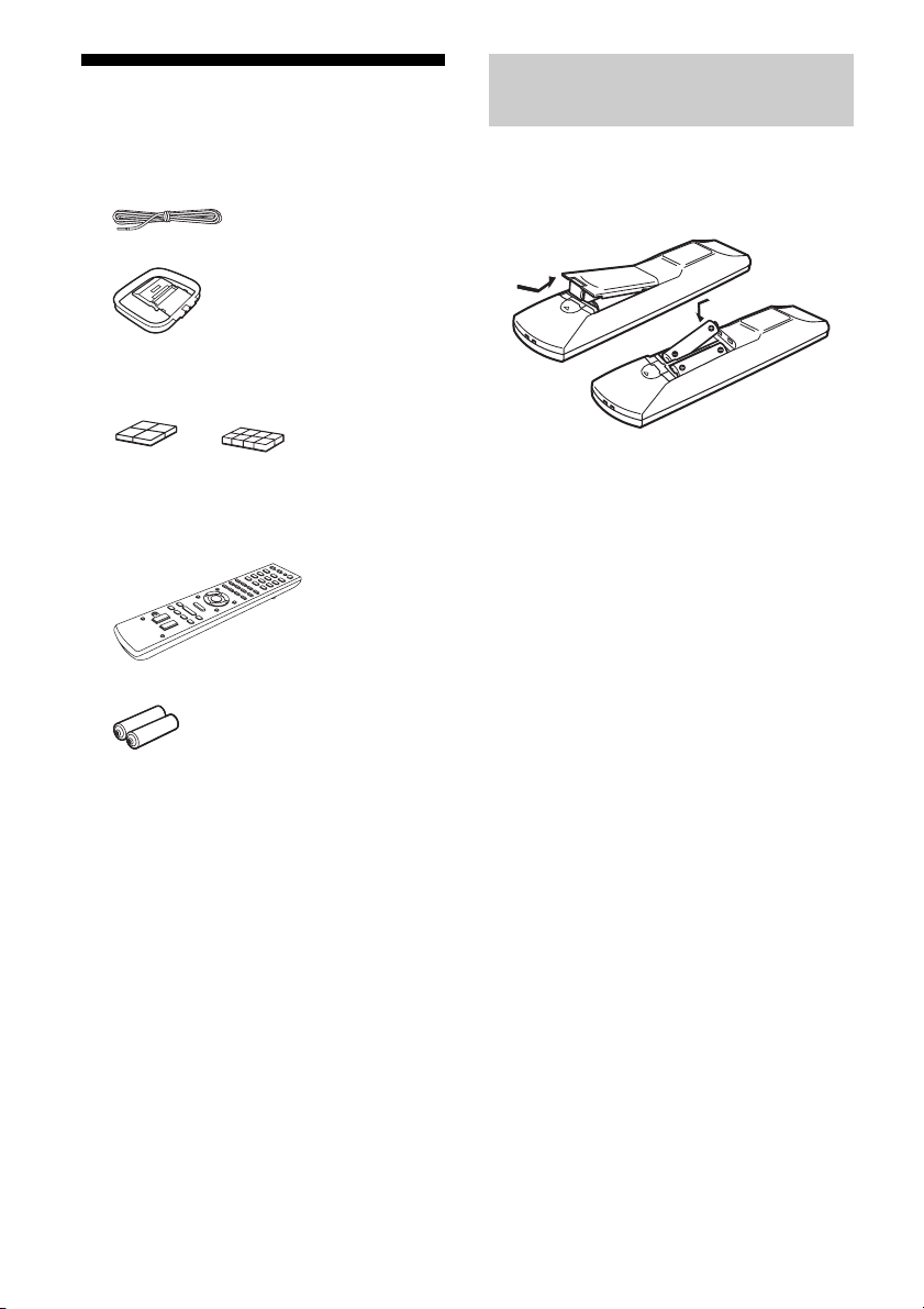
Supplied accessories
• Operating Instructions (this manual)
• Quick Setup Guide (1)
• FM wire antenna (aerial) (1)
• AM loop antenna (aerial) (1)
• Foot pads
– Front speakers and subwoofers
– Surround speakers
(Small) (8)
(Big) (16)
Inserting batteries into the
remote control
Insert two R6 (size AA) batteries (supplied) by
matching 3 and # on the batteries to the
diagram inside the battery compartment of the
remote control.
• Remote control (1)
– RM-AAU136 (South Africa and
Argentina models only)
– RM-AAU135 (Other models)
• R6 (size AA) batteries (2)
Notes
• Do not leave the remote control in an extremely hot
or humid place.
• Do not use a new battery with old ones.
• Do not mix manganese batteries and other kinds of
batteries.
• Do not expose the remote control sensor to direct
sunlight or lighting apparatuses. Doing so may
cause a malfunction.
• If you do not intend to use the remote control for an
extended period of time, remove the batteries to
avoid possible damage from battery leakage and
corrosion.
• When the receiver no longer responds to the
remote control, replace all the batteries with new
ones.
GB
4
Page 5

Description and location of parts
Front panel
* Except for South Africa and Argentina models.
A ?/1 (on/standby) (page 19, 31)
B INPUT SELECTOR (page 21, 22, 24, 26,
27, 28)
C INPUT SELECTOR indicator
Flashes when you change the input source.
D M-TURBO indicator
Lights up when M-TURBO is activated.
E Display panel (page 6)
F MOVIE, MUSIC, GAMING (page 29)
G Remote control sensor
Receives signals from remote control.
H MASTER VOLUME (page 21, 22, 24)
I MASTER VOLUME indicator
Flashes when you adjust the volume.
J (USB) port (page 18)
K M-TURBO
Turns the M-TURBO function on or off.
M-TURBO function reinforces the bass and
creates a more powerful sound.
L SURROUND SPEAKER (page 20)
GB
5
Page 6
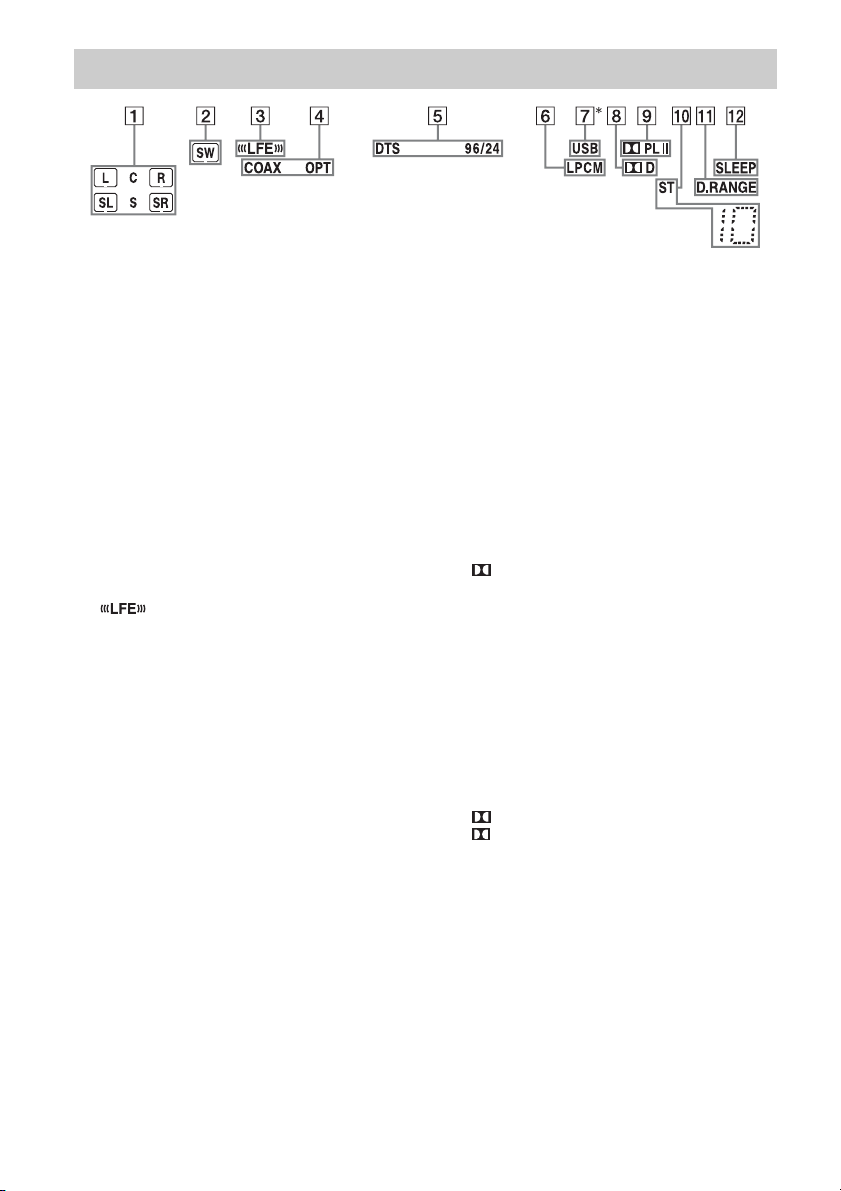
Indicators on the display panel
A Playback channel indicator
The letters (L, C, R, etc.) indicate the channels
being played back. Based on the speaker
settings, the box around the letter(s) vary to
show how the receiver downmixes the source
sound.
L
R
C
SL
SR
S
B SW
Lights up when the audio signal is output from
the SUBWOOFER jack.
C
Lights up when the disc being played back
contains an LFE (Low Frequency Effect)
channel and the LFE channel signal is actually
being reproduced.
D Input indicator
Lights up to indicate the current input.
COAX
Lights up when BD/DVD is selected. However,
“
––––––” appears on the display if no digital
signal is input through the COAXIAL jack (page
15).
OPT
Lights up when GAME or SAT/CATV is
selected. However, “
display if no digital signal is input through the
OPTICAL jack (page 16).
Front Left
Front Right
Center (monaural)
Surround Left
Surround Right
Surround (monaural or the
surround equipment obtained
by Pro Logic processing)
––––––” appears on the
E DTS indicator
Lights up the respective indicator when the
receiver is decoding the corresponding DTS
format signals.
DTS
DTS 96/24
Note
When playing a DTS format disc, make sure that
you have completed the digital connections.
F LPCM
Lights up when the receiver is decoding the
Linear PCM signals.
G USB*
Lights up when a USB device is being played.
H D
Lights up when the receiver is decoding Dolby
Digital signals.
Note
When playing a Dolby Digital format disc, make
sure that you have completed the digital
connections.
I Dolby Pro Logic indicator
Lights up the respective indicator when the
receiver performs Dolby Pro Logic processing.
This matrix surround decoding technology can
enhance input signals.
PL
PL II
DTS
DTS 96 kHz/24 bit
Dolby Pro Logic
Dolby Pro Logic II
GB
6
Page 7

J Tuning indicator
Lights up when the receiver tunes to a radio
station.
ST
Stereo broadcast
Preset station number (The number will change
according to the preset station you select.)
K D.RANGE
Lights up when dynamic range compression is
activated (page 34).
L SLEEP
Lights up when the Sleep Timer is activated
(page 10).
* Except for South Africa and Argentina models.
GB
7
Page 8
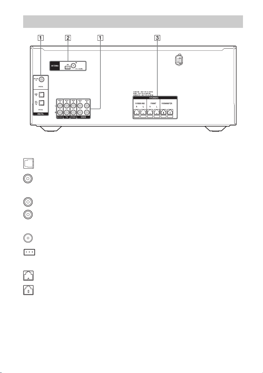
Rear panel
A Audio signal section
DIGITAL INPUT jacks (page 15, 16)
OPTICAL IN
COAXIAL IN
ANALOG INPUT/OUTPUT jacks (page 14, 17)
White (L)
Red (R)
AUDIO IN/OUT
B ANTENNA section (page 18)
FM ANTENNA jack
AM ANTENNA terminal
C SPEAKERS section (page 13)
GB
8
Page 9
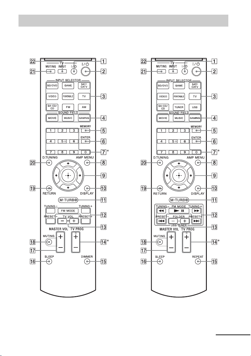
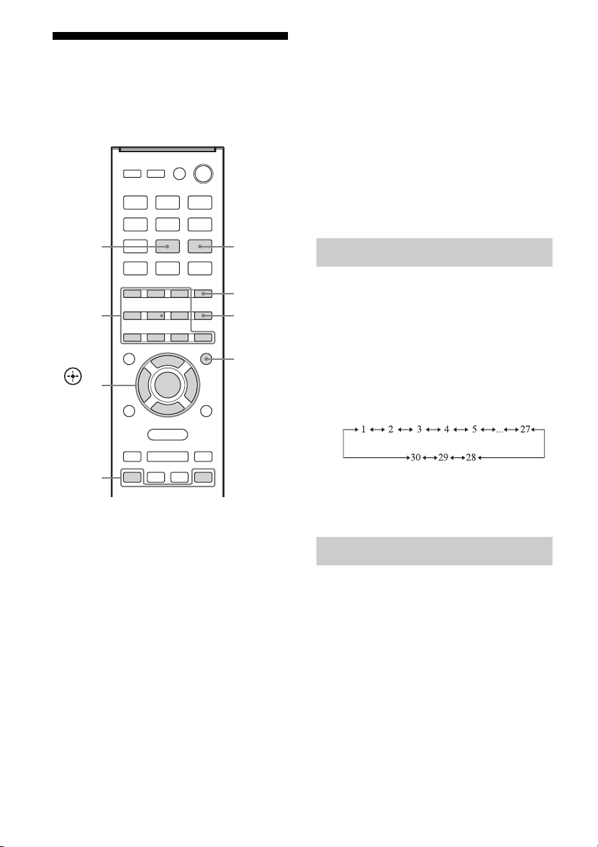
Remote control
Use the supplied remote control to operate this receiver and Sony TV.
• RM-AAU136 (South Africa and
Argentina models only)
• RM-AAU135 (Other models)
* The 5 and TV PROG + buttons have tactile dots. Use the tactile dots as references when operating the
receiver.
continued
GB
9
Page 10

To control the receiver
B ?/1 (on/standby)
Turns the receiver on or sets it to standby mode.
C Input buttons
Selects the equipment you want to use. When
you press any of the input buttons, the receiver
turns on.
D MOVIE, MUSIC, GAMING (page 29)
E MEMORY
Stores a station during tuner operation.
F ENTER
Enters the selections.
G Numeric buttons
Presets or tunes to the preset stations (page 28).
H AMP MENU
Displays the menu to operate the receiver.
I
J DISPLAY
K M-TURBO
L m/M, NX, ./>
M FOLDER +/–
O REPEAT
V/v/B/b
,
Press V/v/B /b to select the settings, then press
to enter/confirm the selection.
Views information on the display panel.
Turns the M-TURBO function on or off.
M-TURBO function reinforces the bass and
creates a more powerful sound.
(RM-AAU135 only)
Operates the USB device: Backward/forward,
play/pause, skip operation.
TUNING +/–
Scans a station.
FM MODE
Selects the FM reception mode (monaural or
stereo).
PRESET +/–
Selects preset stations.
(RM-AAU135 only)
Selects a folder of the USB device.
(RM-AAU135 only)
Plays a track or a folder repeatedly of the USB
device.
DIMMER
(RM-AAU136 only)
Adjusts the brightness of the display panel.
P SLEEP
Sets the receiver to turn off automatically at a
specified time.
The display changes cyclically as follows.
0-30-00 t 1-00-00 t 1-30-00 t 2-00-00 t
OFF
When Sleep Timer is being used, “SLEEP”
indicator lights up on the display panel.
Tip
To check the remaining time before the receiver
turns off, press SLEEP. The remaining time
appears on the display panel. If you press
SLEEP again, the Sleep Timer will be canceled.
Q MASTER VOL +/–
Adjusts the volume level of all speakers at the
same time.
R MUTING
Turns off the sound temporarily.
Press MUTING again to restore the sound.
S RETURN O
Returns to the previous menu.
T D.TUNING
Enters direct tuning mode.
To control a Sony TV
A TV ?/1 (on/standby)
Turns the TV on or off.
M TV VOL +/–
(RM-AAU136 only)
Adjusts the TV volume.
N TV PROG +/–
Scans for the preset TV channels.
U TV MUTING
Activates the TV’s muting function.
V TV INPUT
Selects the input signal (TV or video).
Note
The above explanation is intended to serve as
examples.
10
GB
Page 11
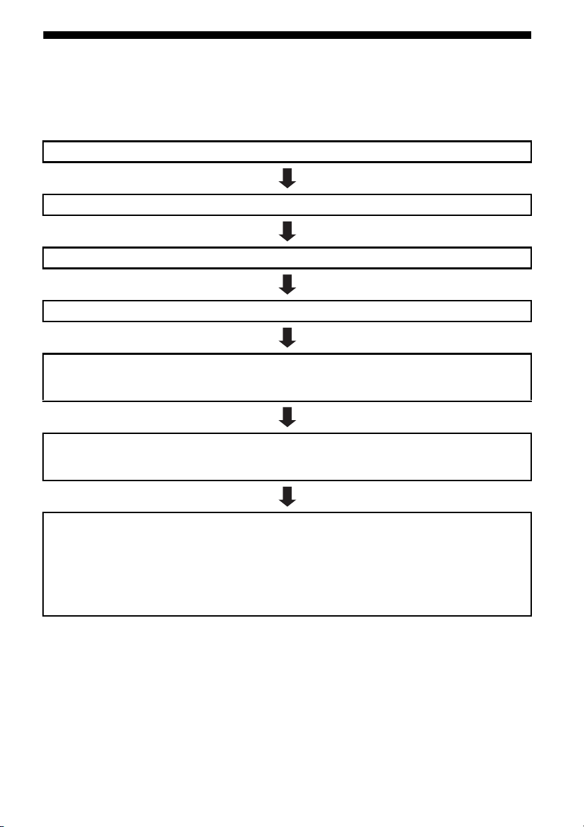
Getting started
You can enjoy your audio/video equipment connected to the receiver by following the simple steps
below.
Before connecting cords, be sure to disconnect the AC power cord (mains lead).
Installing and connecting the speakers (page 12, 13)
Connecting the TV (page 14)
Connecting the video equipment (page 15)
Connecting the audio equipment (page 17)
Preparing the receiver
See “Setting the voltage selector” (page 19), “Connecting the AC power cord (mains lead)” (page 19) and
“Initializing the receiver” (page 19).
Setting the speakers
Select the surround speaker position (page 20), then check the speaker connection using “T. TONE” in
LEVEL menu (page 20). If the sound is not output correctly, check the speaker connection.
Setting the audio output settings on the connected equipment
To output multi channel digital audio, check the digital audio output setting on the connected equipment.
For a Sony Blu-ray Disc player, check that “Dolby Digital” and “DTS” are set to “Dolby Digital” and “DTS”
respectively (as of September 2011).
For a PlayStation 3, check that “BD Audio Output Format (Optical Digital)” is set to “Bitstream” (with
system software version 3.70).
For details, refer to the operating instructions supplied with the connected equipment.
11
GB
Page 12
Connections
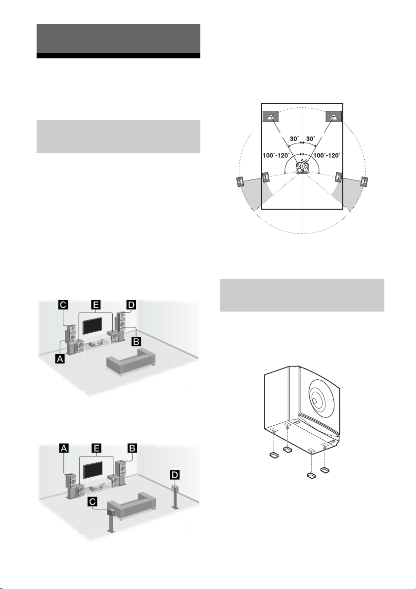
1: Installing the speakers
This receiver allows you to use a 4 channel
speaker with 2 subwoofer system.
Notes
• Do not install the speakers on a wall.
• We recommend that you place the front and
surround speakers on a speaker stand (not
supplied).
Tips
• The angle A should be the same.
Example of speaker system
configuration
You can enjoy different sound effects from the
system by placing the speakers as shown
below.
AFront speaker (left)
BFront speaker (right)
CSurround speaker (left)
DSurround speaker (right)
ESubwoofer
Installing all the speakers in
front position
A A
• Since the subwoofer does not emit highly
directional signals, you can place it wherever you
want.
Installing the speakers on a flat
surface
Before you install the front speakers, surround
speakers and subwoofers, be sure to attach the
supplied foot pads to prevent vibration or
movement as shown in the illustration below.
Installing the surround
speakers in rear position
GB
12
Note
Attach the small foot pads to the surround speakers
and the big foot pads to the front speakers and
subwoofers.
Page 13
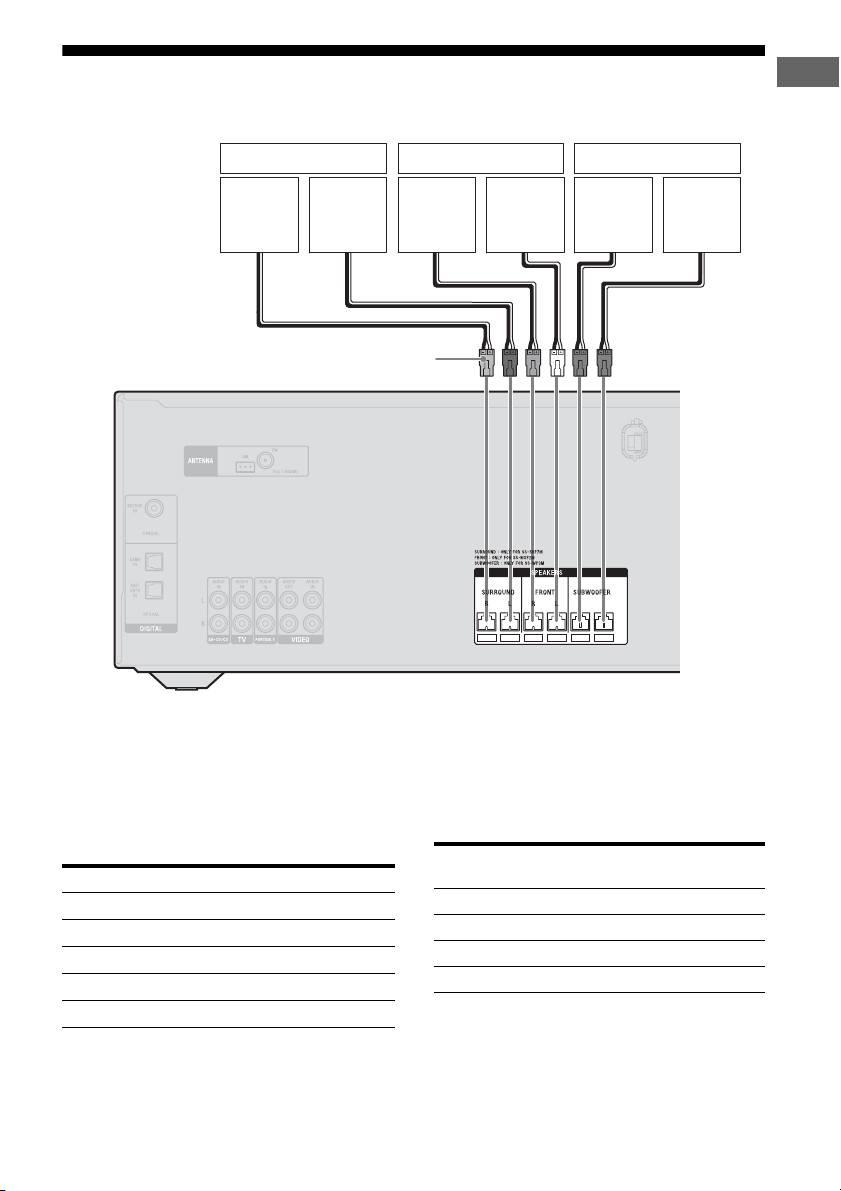
2: Connecting the speakers
Before connecting cords, be sure to disconnect the AC power cord (mains lead).
Surround speaker Front speaker Subwoofer
Connections
Right Left
Connector
Note on speaker cords
The connector of the speaker cords are colorcoded based on the speaker type. When
connecting a speaker cord, be sure to match
the colored connector to the speaker terminal
on the receiver.
Connector Speaker terminal
Purple SUBWOOFER
White FRONT L
Red FRONT R
Blue SURROUND L
Grey SURROUND R
Right Left
To connect the speakers
correctly
Check the speaker type by referring to the
speaker label* on the rear panel of the
speakers.
Character on
speaker label
L Front left
R Front right
SL Surround left
SR Surround right
* The subwoofers do not have any character on the
speaker label. For details on the speaker type, see
page 2.
Speaker type
13
GB
Page 14
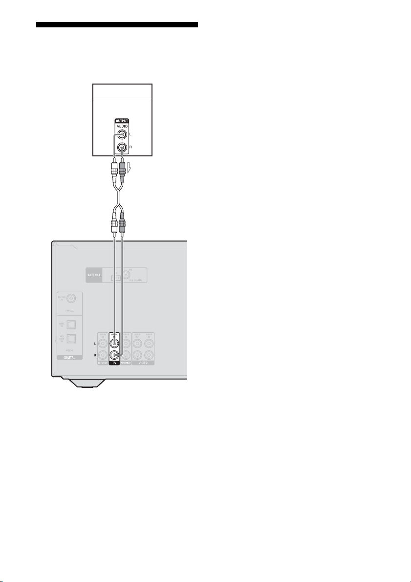
3: Connecting the TV
Before connecting cords, be sure to disconnect
the AC power cord (mains lead).
TV
Audio signals
A
Tips
• To output the sound of the TV from the speakers
connected to the receiver, be sure to
– connect the audio output jacks of the TV to the
TV IN jack of the receiver.
– turn off the TV’s volume or activate the TV’s
muting function.
• When you connect the audio output jack of the TV
to the TV IN jacks of the receiver to output the TV
sound from the speakers connected to the receiver,
set the sound output jack of the TV to “Fixed” if it
can be switched between either “Fixed” or
“Variable”.
A Audio cord (not supplied)
Note
Depending on the status of the connection between
the TV and the antenna (aerial), the image on the TV
screen may be distorted. If this is the case, place the
antenna (aerial) farther away from the receiver.
GB
14
Page 15

4a: Connecting the video equipment
Connecting a Blu-ray Disc
player, DVD player
Blu-ray Disc player, DVD player
Connections
When connecting cords
• Before connecting cords, be sure to
disconnect the AC power cord (mains lead).
• When connecting optical digital cords, insert
the plugs straight until they click into place.
• Do not bend or tie optical digital cords.
Tip
All the digital audio jacks are compatible with
32 kHz, 44.1 kHz, 48 kHz, and 96 kHz sampling
frequencies.
A
Video signalsAudio signals
To t he VI DE O
IN of the TV.
A Coaxial digital cord (not supplied)
15
GB
Page 16

Connecting a PlayStation 3
PlayStation 3
Video signalsAudio signals
A
To the VIDEO
IN of the TV.
Connecting a satellite tuner,
cable TV tuner
Satellite tuner, cable TV tuner
Video signalsAudio signals
A
To the VIDEO
IN of the TV.
A Optical digital cord (not supplied)
GB
16
A Optical digital cord (not supplied)
Page 17

Connecting a VCR, DVD recorder
VCR, DVD recorder
Video signals Audio signals
4b: Connecting the audio equipment
Connecting a Super Audio CD
player, CD player, portable
audio
Connections
A
To th e V ID E O
IN of the TV.
A Audio cord (not supplied)
* If you want to record, you must make this
connection (page 26).
Before connecting cords, be sure to disconnect the
AC power cord (mains lead).
Super Audio
CD player,
CD player
Portable
audio
AB
A Audio cord (not supplied)
B Audio cord with stereo mini-plug (not
supplied)
17
GB
Page 18
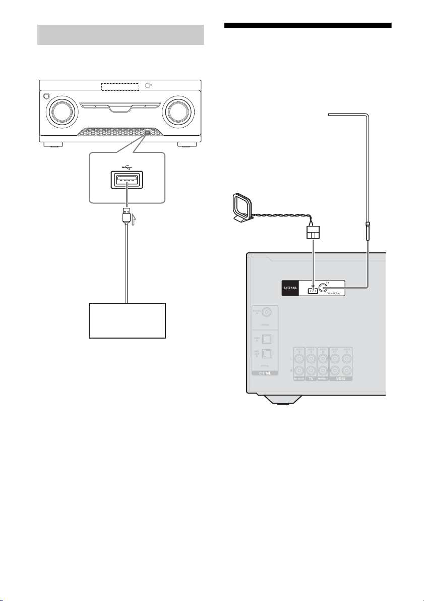
Connecting a USB device
(Except for South Africa and
Argentina models)
A
USB device
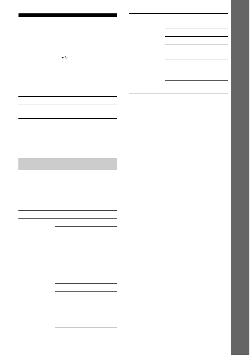
5: Connecting the antennas (aerials)
Before connecting antennas (aerials), be sure
to disconnect the AC power cord (mains lead).
FM wire antenna (aerial)
(supplied)
AM loop antenna (aerial)
(supplied)
A USB cable (not supplied)
GB
18
Notes
• To prevent noise pickup, keep the AM loop
antenna (aerial) away from the receiver and other
equipment.
• Be sure to fully extend the FM wire antenna
(aerial).
• After connecting the FM wire antenna (aerial),
keep it as horizontal as possible.
Page 19

Preparing the Receiver
Initializing the receiver
Setting the voltage selector
If your receiver has a voltage selector on the
rear panel, check that the voltage selector is set
to the local power supply voltage. If not, use a
screwdriver to set the selector to the correct
position before connecting the AC power cord
to a wall outlet.
Depending on the area, the VOLTAGE
SELECTOR may differ.
Connecting the AC power cord (mains lead)
Connect the AC power cord (mains lead) to a
wall outlet.
AC power cord (mains lead)
Before using the receiver for the first time,
initialize the receiver by performing the
following procedure. This procedure can also
be used to revert back to the factory default
settings.
Be sure to use the button on the receiver to
perform this operation.
?/1
1 Press ?/1 to turn off the
receiver.
2 Hold down ?/1 for 5 seconds.
The “CLEARING” appears on the
display panel for a while, then changes to
“CLEARED”.
Changes or adjustments made to the
settings are now reset to the defaults.
Preparing the Receiver
To the wall outlet
19
GB
Page 20

Selecting surround
Adjusting the speaker
speaker position
Select the surround speaker position according
to the speaker configuration.
AMP
MENU
,
V/v/B/b
1 Press AMP MENU.
2 Press V/v repeatedly to select
“SPKR”, then press or b.
3 Press V/v repeatedly to select
“SUR SPK”, then press or b.
4 Press V/v repeatedly to select
the speaker position you want.
• FRONT: If you install all the speakers
in front position, select “FRONT”.
• REAR: If you install the surround/
surround back speakers at rear position,
select “REAR” to enjoy multi channel
surround sound.
Tip
You can also press SURROUND SPEAKER
repeatedly on the receiver to select the surround
speaker position.
levels and balance
(TEST TONE)
You can adjust the speaker levels and balance
while listening to the test tone from your
seating position.
Input
buttons
AMP
MENU
,
V/v/B/b
MASTER
VOL +/–
20
1 Press AMP MENU.
2 Press V/v repeatedly to select
“LEVEL”, then press or b.
3 Press V/v repeatedly to select
“T. TONE”, then press or b.
GB
Page 21

4 Press V/v repeatedly to select
“AUTO xxx
The test tone is output from each speaker
in sequence.
* xxx represent a speaker channel.
*”.
5 Adjust the speaker levels and
balance.
Use the LEVEL menu (page 34) to adjust
the speakers to have the same sounding
test tone level for each speaker.
Tips
•
To adjust the level of all speakers at the same
time, press MASTER VOL +/–. You can also
use MASTER VOLUME on the receiver.
• The adjusted value are shown on the display
panel during adjustment.
6 Exit test tone.
Press any input buttons or select “OFF”
under step 4.
When a test tone is not output
from the speakers
• The speaker cords may not be connected
securely.
• The MASTER VOLUME may has set to
“VOL MIN”.
Basic Operations
Playing an input source equipment
Input
buttons
MOVIE,
MUSIC,
GAMING
AMP
MENU
,
V/v/B/b
MASTER
VOL +/–
Basic Operations
MUTING
1
Press the input button which
corresponds to the equipment
you want.
You can also use INPUT SELECTOR on
the receiver.
The selected input appears on the display
panel.
2 Turn on the equipment and
start playback.
continued
21
GB
Page 22

3 Press MASTER VOL +/– to
adjust the volume.
You can also use MASTER VOLUME on
the receiver.
4 Press MOVIE, MUSIC or
GAMING to enjoy the surround
sound.
For details, see page 29.
To activate the muting function
Press MUTING on the remote control.
The muting function will be canceled when
you do the following.
• Press the button again.
• Increase the volume.
• Turn off the receiver.
To avoid damaging your
speakers
Before you turn off the receiver, be sure to turn
down the volume level.
Naming inputs
You can enter a name of up to 8 characters for
inputs (except TUNER) to appear on the
display panel.
It is more recognizable having the equipment
named on the display than the jacks.
1 Press the corresponding input
button which you want to
create an index name.
You can also use INPUT SELECTOR on
the receiver.
2 Press AMP MENU.
3 Press V/v repeatedly to select
“SYSTEM”, then press or b.
4 Press V/v repeatedly to select
“NAME IN”, then press or b.
The cursor flashes and you can enter a
character.
5 Press V/v to select a character,
then press B/b to move the
input position backward and
forward.
22
Tips
• You can select the character type as follows
by pressing V/v.
Alphabet (upper case) t Numbers t
Symbols
• To enter a blank space, press b without
selecting a character.
If you made a mistake
Press B/b until the character you want to
change flashes, then press V/v to select
the correct character.
6 Press .
The name you entered is registered.
GB
Page 23
Playing a USB device
(Except for South Africa and
Argentina models)
You can enjoy music from the USB device by
connecting it to the (USB) port on the
receiver.
For details on connecting a USB device, see
“Connecting a USB device” (page 18).
The music file formats that can be played back
by this receiver are as follows:
File format Extensions
MP3 (MPEG-1 Audio
Layer III)
AAC* “.m4a”, “.3gp”, “.mp4”
WMA9 Standard* “.wma”
* The receiver does not play files encoded with
DRM.
Compatible USB devices
You can use the following Sony USB devices
on this receiver. Other USB devices cannot be
used on this receiver.
Verified Sony USB device
Product name Model name
Walkman
®
“.mp3”
NWZ-S754 / S755
NWZ-E453 / E454 / E455
NWZ-E353 / E354 / E355
NWZ-B133 / B135 / B133F /
B135F
NWZ-B142 / B143 / B142F /
B143F
NWD-E023F / E025F
NWZ-E435F / E436F / E438F
NWZ-E343 / E344 / E345
NWZ-S636F / S638F / S639F
NWZ-S736F / S738F / S739F
NWZ-A726 / A728 / A729 /
A726B / A728B
NWZ-A826 / A828 / A829
Product name Model name
NWZ-W202
NWZ-X1050 / X1060
NWZ-S744 / S745
NWZ-E443 / E444 / E445
NWZ-S543 / S544 / S545
NWZ-A844 / A845 / A846 /
A847
NWZ-W252 / W253
NWZ-B152 / B153 / B152F /
B153F
MICROVAULT USM1GL / 2GL / 4GL / 8GL /
16GL
USM1GLX / 2GLX / 4GLX /
8GLX / 16GLX
Notes
• The receiver is unable to read data in NTFS format.
• The receiver is unable to read data other than that
saved in the first partition of a hard disk drive.
• Do not use USB devices other than these USB
devices. Operation of models not listed here is not
guaranteed.
• Operation may not always be ensured even when
using these USB devices.
• Some of these USB devices may not be available
for purchase in certain areas.
• When formatting the above models, be sure to
format using the model itself or the dedicated
formatting software for that model.
• When connecting a USB device to the receiver, be
sure to connect after the display “Creating Library”
or “Creating Database” on the USB device has
disappeared.
Basic Operations
23
GB
Page 24

Operating the USB device
USB
MOVIE,
MUSIC,
GAMING
NX
./>
MASTER
VOL +/–
m/M
FOLDER
+/–
REPEAT
1 Press USB.
You can also use INPUT SELECTOR on
the receiver.
When the USB device is connected,
“USB” indicator appears on the display
panel.
2 Press NX to start playback.
3 Press MASTER VOL +/– to
adjust the volume.
You can also use MASTER VOLUME on
the receiver.
4 Press MOVIE, MUSIC or
GAMING to enjoy the surround
sound.
For details, see page 29.
Other operations
Press Operation
NX Starts/pauses play.
m/M Fast reverses or forwards.
./> Goes to the previous/next file.
FOLDER +/– Goes to the previous/next folder.
REPEAT Enters repeat mode.
• RPT. OFF/RPT. ONE/
RPT. ALL/RPT. FLD
Notes on the USB device
• Do not remove the USB device during
operation. To avoid data corruption or
damage to the USB device, turn the receiver
off when removing the USB device.
• When USB cable connection is necessary,
connect the USB cable supplied with the
USB device to be connected. Refer to the
operating instructions supplied with the
USB device to be connected for details on
the operation method.
• Do not connect the receiver and the USB
device through a USB hub.
• When the USB device is connected,
“READING” appears.
• It may take about 10 seconds before
“READING” appears depending on the type
of USB device connected.
• When the USB device is connected, the
receiver reads all the files on the USB
device. If there are many folders or files on
the USB device, it may take a long time to
finish reading the USB device.
• The receiver can recognize up to
– 100 folders (including “ROOT” folder).
– 100 audio files for each folder.
– 8 folder levels (tree structure of files,
including “ROOT” folder).
The maximum number of audio files and
folders may vary depending on the file and
folder structure.
Do not save other types of files or
unnecessary folders on a USB device.
24
GB
Page 25

• Compatibility with all encoding/writing
softwares, recording devices, and recording
media cannot be guaranteed. Incompatible
USB device may produce noise or
interrupted audio or may not play at all.
• Some time may be needed to start playback
when:
– the folder structure is complex.
– the memory capacity is excessive.
• This receiver does not necessarily support
all the functions provided in a connected
USB device.
• The playback order for the receiver may
differ from the playback order of the
connected USB device.
• Folders that have no audio files are skipped.
• When playing a very long track, some
operations may cause playback delay.
USB message list
Message and explanation
READING
The receiver is recognizing and reading information
of the USB device.
DEVICE ERROR
The memory of the USB device could not be
recognized (page 23).
NO SUPPORT
An unsupported USB device is connected, an
unknown device is connected, or the
USB device is connected through a USB hub
(page 23).
NO.DEVICE
No USB device is connected or the connected USB
device is not recognized.
NO TRACK
No track was found.
Viewing information on the display panel
The display panel provides various
information of the receiver status such as
sound field.
Input
buttons
AMP
MENU
DISPLAY
1 Press the corresponding input
button which you want to check
the information.
2 Press DISPLAY repeatedly.
Each time you press the button, the
display changes cyclically as follows:
Index name of the input* t Selected
input t Sound field currently applied t
Volume level t Stream info**
When listening to FM and AM radio
Preset station name* t Frequency t
Sound field currently applied t Volume
level
* Index name appears only when you have
assigned one to the input or preset station
(page 22, 28). Index name does not appear
when only blank spaces have been entered,
or it is the same as the input name.
**Stream information may not be displayed.
continued
25
Basic Operations
GB
Page 26

Note
Character or marks may not be displayed for some
languages.
Recording using the receiver
You can only record audio signals from an
audio/video equipment using the receiver.
Refer to the operating instructions supplied
with your recording equipment.
1 Press one of the input button to
select the playback equipment
that you want to record.
You can also use INPUT SELECTOR on
the receiver.
2 Prepare the playback
equipment for playing.
For example, insert the CD you want to
copy into the CD player.
3 Prepare the recording
equipment.
Insert a blank video tape, etc. into the
recording equipment (connected to
VIDEO OUT jacks).
4 Start recording on the
recording equipment, then start
the playback equipment.
Notes
• Sound adjustments do not affect the signal output
from the VIDEO OUT jacks.
• Some sources contain copyright protection to
prevent recording. In this case, you may not be able
to record from the source.
• Audio input signals via DIGITAL IN jacks cannot
be recorded.
• While the source is being recorded, the auto
standby function of the receiver may start up and
interrupt the recording. In this case, set the
“AUTO.STBY” to “STBY OFF” (page 35).
Tuner Operations
Listening to FM/AM radio
You can listen to FM and AM broadcasts
through the built-in tuner. Before operation,
make sure you have connected the FM and
AM antennas (aerials) to the receiver (page
18).
Tip
The tuning scale for direct tuning is shown below.
Area FM AM
Latin America and
Argentina
South Africa 50 kHz 9 kHz
* The AM tuning scale can be changed (page 27).
TUNER1)/
2)
FM
Numeric
buttons
D.TUNING
,
V/v/B/b
FM MODE
1)
RM-AAU135 only.
2)
RM-AAU136 only.
50 kHz 10 kHz*
2)
AM
ENTER
AMP
MENU
TUNING
+/–
26
GB
Page 27

Tuning to a station
automatically (Automatic
Tuning)
1 Press TUNER repeatedly (or
press FM or AM) to select the
FM or AM band.
You can also use INPUT SELECTOR on
the receiver.
2 Press TUNING + or TUNING –.
TUNING + scans from lower to higher
frequency stations and TUNING – for
scanning higher to lower.
The receiver stops scanning whenever a
station is received.
In case of poor FM stereo
reception
If the FM stereo reception is poor and “ST”
flashes on the display panel, select monaural
audio to lessen the sound distortion.
Press FM MODE repeatedly to select
“MONO”. To return to stereo mode, press
FM MODE repeatedly to select “STEREO”.
3 Press the numeric buttons to
enter the frequency.
Example 1: FM 102.50 MHz
Select 1 b 0 b 2 b 5 b 0
Example 2: AM 1,350 kHz
Select 1 b 3 b 5 b 0
Tip
Adjust the direction of the AM loop antenna
(aerial) for optimum reception upon tuning to
an AM station.
4 Press ENTER.
Tuner Operations
If you cannot tune to a station
“–––.––MHz” or “––––kHz” appears and
then the display panel returns to the current
frequency.
Make sure you have entered the right
frequency. Try repeating steps 2 to 4. If you
still cannot tune to a station, the frequency
may not be in use in your area.
Changing the AM tuning scale
(Latin America and Argentina
models only)
Tuning to a station directly
(Direct Tuning)
You can enter the frequency of a station
directly by using the numeric buttons.
1 Press TUNER repeatedly (or
press FM or AM) to select the
FM or AM band.
You can also use INPUT SELECTOR on
the receiver.
2 Press D.TUNING.
You can change the AM tuning scale to either
9 kHz or 10 kHz.
1 Press TUNER repeatedly (or
press AM) to select AM.
2 Press AMP MENU.
3 Press V/v repeatedly to select
“TUNER”, then press or b.
4 Press V/v repeatedly to select
“AM STEP”, then press or b.
5 Press V/v repeatedly to select
the AM tuning scale you want.
Note
All AM preset stations will be erased when you
change the tuning scale.
27
GB
Page 28
Presetting FM/AM radio stations
You can store up to 30 FM and 30 AM stations
as your favorite stations as preset stations.
4 Press the numeric buttons to
select a preset number.
You can also press PRESET + or
PRESET – to select a preset number.
5 Press ENTER.
The station is stored as the selected preset
number.
6 Repeat steps 1 to 5 to store
another station.
TUNER1)/
2)
FM
Numeric
buttons
,
V/v/B/b
PRESET
+/–
1)
RM-AAU135 only.
2)
RM-AAU136 only.
2)
AM
MEMORY
ENTER
AMP
MENU
1 Press TUNER repeatedly (or
press FM or AM) to select the
FM or AM band.
You can also use INPUT SELECTOR on
the receiver.
2 Tune to the station that you
want to preset using Automatic
Tuning (page 27) or Direct
Tuning (page 27).
3 Press MEMORY.
Tuning to preset stations
1 Press TUNER repeatedly (or
press FM or AM) to select the
FM or AM band.
2 Press PRESET + or PRESET –
repeatedly to select the station.
Each time you press the button, you can
select a preset station as follows:
You can also press the numeric buttons to
enter the preset station. To tune to the
selection, press ENTER.
Naming preset stations
1 Press TUNER repeatedly (or
press FM or AM) to select the
FM or AM band.
You can also use INPUT SELECTOR on
the receiver.
2 Tune to the preset station you
want to create an index name
for (page 28).
3 Press AMP MENU.
28
GB
Page 29

4 Press V/v repeatedly to select
“TUNER”, then press or b.
Enjoying Surround Sound
5 Press V/v repeatedly to select
“NAME IN”, then press or b.
The cursor flashes and you can enter a
character.
6 Press V/v to select a character,
then press B/b to move the
input position backward and
forward.
You can enter up to 8 characters to name
the station.
Tips
• You can select the character type as follows
by pressing V/v.
Alphabet (upper case) t Numbers t
Symbols
• To enter a blank space, press b without
selecting a character.
If you made a mistake
Press B/b until the character you want to
change flashes, then press V/v to select
the correct character.
7 Press .
The name you entered is registered.
Selecting the sound field
This receiver can create multi channel
surround sound. You can select one of the
optimized sound fields from the receiver’s
pre-programmed sound fields.
MOVIE,
MUSIC,
GAMING
Press MOVIE, MUSIC or GAMING to
select the sound field you want.
Note
Before selecting the sound field, be sure to select the
surround speaker position according to the speaker
configuration. For details, see “Selecting surround
speaker position” (page 20).
x MOVIE A (Movie A)
Optimizes sound output from all speakers for
movie playback.
Enjoying Surround Sound
x MOVIE B (Movie B)
Reproduces a movie effect sound.
x MUSIC (Music)
Reproduces music sound with multi channel
output.
x GAMING (Gaming)
Reproduces the sound processing of video
games for better gaming experience.
continued
29
GB
Page 30

Notes on sound fields
• The sound fields for music and movie do not
work for signals with a sampling frequency
of more than 48 kHz.
• The effects provided by the virtual speakers
may cause increased noise in the playback
signal.
• When listening with sound fields that
employ the virtual speakers, you will not be
able to hear any sound coming directly from
the surround speakers.
Tip
You can identify the encoding format of DVD
software, etc., by looking at the logo on the package.
To turn off the surround effect
Press MOVIE repeatedly to select
“MOVIE A”.
Digital audio formats supported by the receiver
Digital audio formats that this receiver can decode depend on digital audio output jacks of the
connected equipment. This receiver supports the following audio formats.
Audio format
Dolby Digital 5.1 a
DTS 5.1 a
DTS 96/24 5.1 a
Maximum number
of channels
COAXIAL/OPTICAL connection between the
playback equipment and the receiver
30
GB
Page 31

Resetting sound fields to the default settings
Be sure to use the buttons on the receiver to
perform this operation.
?/1
MUSIC
Menu Operations
Using the setting menu
You can customize the receiver by making
various adjustments with settings menu.
AMP
MENU
,
V/v/B/b
RETURN
O
1 Press ?/1 to turn off the
receiver.
2 While holding down MUSIC,
press ?/1.
“S.F. CLEAR” appears on the display
panel and all sound fields are reset to their
default setting.
1 Press AMP MENU.
2 Press V/v repeatedly to select
the menu item you want, then
press or b.
3 Press V/v repeatedly to select
the parameter you want to
adjust, then press or b.
4 Press V/v repeatedly to select
the setting you want, then
press .
To return to the previous
display
Press B or RETURN O.
To exit the menu
Press AMP MENU.
Note
Some parameters and settings may appear dimmed
on the display panel. This means that they are either
unavailable or fixed and unchangeable.
Menu Operations
31
GB
Page 32

Overview of the menus
The following options are available in each menu. For details, see the referencing page in the
parentheses.
Menu
[Display]
LEVEL
[LEVEL]
(page 34)
SPEAKER
[SPKR]
(page 34)
EQ
[EQ]
(page 34)
TUNER
[TUNER]
(page 34)
Parameters
[Display]
Tes t tone
[T. TONE]
Front speaker balance
[FRT BAL]
Surround left speaker level
[SL LVL]
Surround right speaker level
[SR LVL]
Subwoofer level
[SW LVL]
Dynamic range compressor
[D. RANGE]
Surround speaker position
[SUR SPK]
Front left speaker distance
[FL DIST.]
Front right speaker distance
[FR DIST.]
Surround left speaker distance
[SL DIST.]
Surround right speaker distance
[SR DIST.]
Subwoofer distance
[SW DIST.]
Front speakers bass level
[BASS]
Front speakers treble level
[TREBLE]
Naming preset stations
[NAME IN]
AM tuning scale selection
[AM STEP]
b)
Settings Default
AUTO xxx
BAL. L+1 to BAL. L+8, BALANCE,
BAL. R+1 to BAL. R+8
SL –10.0 dB to SL +10.0 dB
(0.5 dB interval)
SR –10.0 dB to SR +10.0 dB
(0.5 dB interval)
SW –10.0 dB to SW +10.0 dB
(0.5 dB interval)
COMP. MAX, COMP. STD,
COMP. OFF
FRONT, REAR FRONT
1.00 m to 10.00 m (0.10 m interval) 3.00 m
BASS –6 dB to BASS +6 dB
(1 dB interval)
TRE –6 dB to TRE +6 dB
(1 dB interval)
For details, see “Naming preset
stations” (page 28).
For details, see “Changing the AM
tuning scale” (page 27).
a)
, OFF OFF
setting
BALANCE
SL 0 dB
SR 0 dB
SW 0 dB
COMP. OFF
BASS 0 dB
TRE 0 dB
32
GB
Page 33

Menu
[Display]
AUDIO
[AUDIO]
(page 35)
Parameters
[Display]
Synchronizes audio with video
output
[A/V SYNC]
Digital broadcast language
Settings Default
setting
SYNC ON, SYNC OFF SYNC OFF
MAIN/SUB, MAIN, SUB MAIN
selection
[DUAL]
Pro Logic II Decoding mode
c)
AUTO, ON, OFF AUTO
[PLII DEC.]
SYSTEM
[SYSTEM]
(page 35)
Brightness of the display panel
[DIMMER]
Auto standby mode
DIM ON, DIM OFF DIM OFF
STBY ON, STBY OFF STBY ON
[AUTO.STBY]
Naming inputs
[NAME IN]
a)
xxx represent a speaker channel (FL, FR, SL, SR, SW).
b)
Latin America and Argentina models only.
c)
You can only select this parameter if the sound field is set to “MOVIE A” and surround speaker position is
For details, see “Naming inputs”
(page 22).
set to “REAR”.
Menu Operations
33
GB
Page 34

LEVEL menu SPEAKER menu
You can adjust the level and balance of each
speaker manually.
x T. TONE
Lets you adjust the speaker levels and balance
while listening to the test tone from your
seating position (page 20).
x FRT BAL
Lets you adjust the balance between front left
and right speakers.
x SL LVL, SR LVL, SW LVL
You can adjust each speaker’s level (surround
left/right, subwoofer).
x D. RANGE
Lets you compress the dynamic range of the
soundtrack. This may be useful when you want
to watch movies at low volumes late at night.
Dynamic range compression is possible with
Dolby Digital sources only.
•COMP. MAX
The dynamic range is compressed
dramatically.
• COMP. STD
The dynamic range is compressed as
intended by the recording engineer.
•COMP. OFF
The dynamic range is not compressed.
Tip
Dynamic range compressor lets you compress the
dynamic range of the soundtrack based on the
dynamic range information included in the Dolby
Digital signal.
“COMP. STD” is the standard setting, and enacts
light compression. Therefore, we recommend using
the “COMP. MAX” setting. This greatly compresses
the dynamic range and lets you view movies late at
night at low volumes. Unlike analog limiters, the
levels are predetermined and provide a very natural
compression.
You can adjust the position and distance of the
speakers connected to this receiver.
x SUR SPK
Lets you select the surround speaker position
according to the speaker configuration (page
20).
x FL DIST., FR DIST., SL DIST.,
SR DIST., SW DIST.
Lets you adjust the distance from your seating
position to each speaker (front left/right,
surround left/right, subwoofer).
If both front speakers are not placed in equal
distance from your seating position, set the
distance to the closest speaker.
EQ menu
You can adjust the tonal quality (bass/treble
level) of the front speakers.
x BASS
x TREBLE
TUNER menu
You can name the preset stations.
x NAME IN
Lets you set the name of preset stations. For
details, see “Naming preset stations” (page
28).
x AM STEP*
Lets you change the AM STEP to either 9 kHz
or 10 kHz. For details, see “Changing the AM
tuning scale” (page 27).
* Latin America and Argentina models only.
34
GB
Page 35

AUDIO menu
You can adjust settings for the audio to suit
your preference.
x A/V SYNC
Lets you delay the output of audio to minimize
the time gap between audio output and visual
display.
• SYNC ON (Delay time: 60 ms)
The audio output is delayed so that the time
gap between the audio output and visual
display is minimized.
• SYNC OFF (Delay time: 0 ms)
The audio output is not delayed.
Notes
• This parameter is useful when you use a large LCD
or plasma monitor or a projector.
• The delay time may vary depending on audio
format, sound field and speaker distance settings.
x DUAL
Lets you select the language you want to listen
to during digital broadcast when available.
This feature only functions for Dolby Digital
sources.
• MAIN/SUB
Sound of the main language will be output
through the front left speaker and sound of
the sub language will be output through the
front right speaker simultaneously.
•MAIN
Sound of the main language will be output.
•SUB
Sound of the sub language will be output.
x PLII DEC.
Lets you turn the Pro Logic II decoding mode
on or off.
•AUTO
Applies the Pro Logic II decoding mode
automatically when receiving the Dolby
Surround encoded signals.
•ON
Applies the Pro Logic II decoding mode
when receiving 2 channels signals.
•OFF
Pro Logic II decoding mode is turned off.
Note
This function works only in the following cases.
– “MOVIE A” is selected.
– Surround speaker position is set to “REAR”.
SYSTEM menu
You can customize the settings of the receiver.
x DIMMER
Lets you adjust the brightness of the display
panel.
•DIM ON
The brightness of the display is reduced and
the indicators light off.
•DIM OFF
The brightness of the display and the
indicators remain unchanged.
x AUTO.STBY
Lets you set the receiver switch to standby
mode automatically when you do not operate
the receiver or when there is no signals input to
the receiver.
• STBY ON
Switches to standby mode after
approximately 30 minutes.
• STBY OFF
Does not switch to standby mode.
Notes
• This function does not work when TUNER input is
selected.
• If you use the Auto standby mode and the Sleep
Timer at the same time, the Sleep Timer has
priority.
x NAME IN
Lets you set the name of inputs. For details,
see “Naming inputs” (page 22).
Menu Operations
35
GB
Page 36

Additional Information
Precautions
On safety
Should any solid object or liquid fall into the
cabinet, unplug the receiver and have it
checked by qualified personnel before
operating it any further.
On power sources
• Before operating the receiver, check that the
operating voltage is identical with your local
power supply.
The operating voltage is indicated on the
nameplate on the back of the receiver.
• The unit is not disconnected from the AC
power source (mains) as long as it is
connected to the wall outlet, even if the unit
itself has been turned off.
• If you are not going to use the receiver for a
long time, be sure to disconnect the receiver
from the wall outlet. To disconnect the AC
power cord (mains lead), grasp the plug
itself; never pull the cord.
• The AC power cord (mains lead) must be
changed only at a qualified service shop.
On heat buildup
Although the receiver heats up during
operation, this is not a malfunction. If you
continuously use this receiver at a large
volume, the cabinet temperature of the top,
side and bottom rises considerably. To avoid
burning yourself, do not touch the cabinet.
On placement
• Place the receiver in a location with adequate
ventilation to prevent heat buildup and
prolong the life of the receiver.
• Do not place the receiver near heat sources,
or in a place subject to direct sunlight,
excessive dust, or mechanical shock.
• Do not place anything on top of the cabinet
that might block the ventilation holes and
cause malfunctions.
• Do not place the receiver near equipment
such as a TV, VCR, or tape deck. (If the
receiver is being used in combination with a
TV, VCR, or tape deck, and is placed too
close to that equipment, noise may result,
and picture quality may suffer. This is
especially likely when using an indoor
antenna (aerial). Therefore, we recommend
using an outdoor antenna (aerial).)
• Use caution when placing the receiver or
speakers on surfaces that have been specially
treated (with wax, oil, polish, etc.) as staining
or discoloration of the surface may result.
On operation
Before connecting other equipment, be sure to
turn off and unplug the receiver.
If you encounter color
irregularity on a nearby TV
screen
As all the speakers and subwoofers are not
magnetically shielded, we recommend that
you place them slightly further away from a
TV set (page 12).
If color irregularity is
observed...
Turn off the TV set, then turn it on again after
15 to 30 minutes.
If color irregularity is observed
again...
Place the speakers further away from the TV
set.
On cleaning
Clean the cabinet, panel, and controls with a
soft cloth slightly moistened with a mild
detergent solution. Do not use any type of
abrasive pad, scouring powder, or solvent,
such as alcohol or benzine.
36
GB
Page 37

If you have any questions or problems
concerning your receiver, please consult your
nearest Sony dealer.
Troubleshooting
If you experience any of the following
difficulties while using the receiver, use this
troubleshooting guide to help you remedy the
problem. Should any problem persist, consult
your nearest Sony dealer. Note that if service
personnel changes some parts during repair,
these parts may be retained.
Power
The receiver is turned off automatically.
• “AUTO.STBY” is set to “STBY ON”
(page 35).
• The Sleep Timer function is working (page
10).
Sound
There is no sound, no matter which
equipment is selected, or only a very
low-level sound is heard.
• Check that all connecting cords are
inserted to their input/output jacks for the
respective jacks of the receiver, speakers
and the equipment.
• Check that both the receiver and all
equipment are turned on.
• Check that MASTER VOLUME is not set
to “VOL MIN”.
• Press MUTING on the remote control to
cancel the muting function.
• Try pressing the input button on the remote
control or turning INPUT SELECTOR on
the receiver to select the equipment of
your choice (page 21).
There is severe hum or noise.
• Check that the speakers and equipment are
connected securely.
• Check that the connecting cords are away
from a transformer or motor, and at least
3 meters (10 feet) away from a TV set or
fluorescent light.
• Move your audio equipment away from
the TV.
• The plugs and jacks are dirty. Wipe them
with a cloth slightly moistened with
alcohol.
There is no sound, or only a very lowlevel sound is heard from specific
speakers.
• Check that all the cords are fully inserted
into the jacks on both the receiver and the
equipment.
• Make sure you have connected to both the
L and R jacks of an analog equipment,
analog equipment requires both L and R
jack connections. Use an audio cord (not
supplied).
• Adjust the speaker level (page 20).
• Check that the speaker cords are
connected correctly and securely (page
13).
• Check that the subwoofer is connected
correctly and securely.
There is no sound from a specific
equipment.
• Check that the equipment is connected
correctly to the audio input jacks for that
equipment.
• Check that the cord(s) used for the
connection is (are) fully inserted into the
jacks on both the receiver and the
equipment.
The left and right sounds are
unbalanced or reversed.
• Check that the speakers and equipment are
connected correctly and securely.
Additional Information
continued
37
GB
Page 38

• Adjust the level parameters using the
LEVEL menu.
Dolby Digital or DTS multi channel
sound is not reproduced.
• Check that the DVD, etc. you are playing is
recorded in Dolby Digital or DTS format.
• When connecting the DVD player, etc., to
the digital input jacks of this receiver, make
sure the digital audio output setting of the
connected equipment is available.
The surround effect cannot be obtained.
• Make sure the sound field is not set to
“
MOVIE A” (page 29).
Recording cannot be carried out.
• Check that the equipment are connected
correctly.
• Select the source equipment using the
input buttons (page 21).
• Audio input signals via DIGITAL IN jacks
cannot be recorded.
• Copyright protection to prevent recording
is contained in the sources. In this case,
you may not be able to record from the
sources.
Tuner
The FM reception is poor.
• Use a 75-ohm coaxial cable (not supplied)
to connect the receiver to an outdoor FM
antenna (aerial) as shown below.
Outdoor FM antenna (aerial)
• The signal strength of the stations is too
weak with automatic tuning. Use direct
tuning.
• Make sure you set the tuning scale
correctly (when tuning in AM stations
with direct tuning) (page 27).
• No stations have been preset or the preset
stations have been cleared (when tuning by
scanning preset stations is used). Preset the
stations (page 28).
• Press DISPLAY repeatedly so that the
frequency appears on the display panel.
USB device
Are you using a supported USB
device?
• If you connect an unsupported USB
device, the following problems may occur.
See “Compatible USB devices” (page 23)
for the supported device types.
– The USB device is not recognized.
– File or folder names are not displayed
on this receiver.
– Playback is not possible.
– The sound skips.
– There is noise.
– A distorted sound is output.
There is noise, skipping, or distorted
sound.
• Turn off the receiver and reconnect the
USB device, then turn on the receiver.
• The music data itself contains noise, or the
sound is distorted.
Receiver
Radio stations cannot be tuned in.
• Check that the antennas (aerials) are
connected securely. Adjust the antennas
(aerials) and connect an external antenna
(aerial), if necessary.
GB
38
The USB device is not recognized.
• Turn off the receiver, then disconnect the
USB device. Turn on the receiver again
and reconnect the USB device.
• Connect the supported USB device
(page 23).
• The USB device does not work properly.
Refer to the USB device operating
instruction on how to deal with this
problem.
Page 39

Playback does not start.
• Turn off the receiver and reconnect the
USB device, then turn on the receiver.
• Connect the supported USB device
(page 23).
•Press NX to start playback.
The USB device cannot be connected
into the (USB) port.
• The USB device is being connected upside
down. Connect the USB device in the
correct orientation.
Erroneous display.
• The data stored in the USB device may
have been corrupted.
• The character codes that can be displayed
by this receiver are as follows:
– Upper cases (A to Z)
– Numbers (0 to 9)
– Symbols (= < > * + , – . / [ \ ] _)
Other characters may not be displayed
correctly.
“READING” is displayed for an
extended time, or it takes a long time
before playback starts.
• The reading process can take a long time
in the following cases.
– There are many folders or files on the
USB device.
– The file structure is extremely complex.
– The memory capacity is excessive.
– The internal memory is fragmented.
Thus, we recommend following these
guidelines.
– Total folders on USB device: 100 or less
(including “ROOT” folder)
– Total files per folder: 100 or less.
Audio file cannot be played back.
• MP3 files in MP3 PRO format cannot be
played back.
• The audio file is a multiple track audio file.
• Some AAC files may not be played back
correctly.
• WMA files in Windows Media Audio
Lossless and Professional format cannot
be played back.
• USB device formatted with file systems
other than FAT16 or FAT32 are
unsupported.*
• If you use partitioned USB device, only
audio files on the first partition can be
played back.
• Playback is possible up to 8 levels
(including “ROOT” folder).
• The number of folders has exceeded 100
(including “ROOT” folder).
• The number of files in a folder has
exceeded 100.
• Files that are encrypted or protected by
passwords, etc. cannot be played back.
* This receiver supports FAT16 and FAT32, but
some USB device may not support all of these
FAT. For details, refer to the operating
instruction of each USB device or contact the
manufacturer.
Remote control
The remote control does not function.
• Point the remote control at the remote
control sensor on the receiver (page 5).
• Remove any obstacles in the path between
the remote control and the receiver.
• Replace all the batteries in the remote
control with new ones, if they are weak.
• Make sure you select the correct input on
the remote control.
Error messages
If there is a malfunction, a message appears on
the display panel. You can check the condition
of the system by the message. If any problem
persists, consult your nearest Sony dealer.
If an error message appears while you use a
USB device, see “USB message list” (page
25).
continued
39
Additional Information
GB
Page 40

PROTECT
Irregular current is output to the speakers, or
the receiver is covered and ventilation holes
are blocked. The receiver will automatically
turn off after a few seconds. Remove the
object covering the upper panel of the
receiver, check the speaker connection, and
turn on the power again.
USB FAIL
An over current from the (USB) port
was detected. The receiver will
automatically turn off after a few seconds.
Check the USB device, then unplug it and
turn on the power again.
Clearing the memory
Reference sections
To clear See
All memorized settings page 19
Customized sound fields page 31
Specifications
Amplifier section
Power Output
Latin America and Argentina models
Stereo mode output (rated) (6 ohms, 1 kHz,
THD 1%)
104 W + 104 W
Surround mode output
2)
(reference) (6 ohms,
1 kHz, THD 30%)
RMS output
FRONT: 220 W per channel
SURROUND: 220 W per channel
Surround mode2) (reference) (6 ohms, 100 Hz,
THD 30%)
SUBWOOFER: 220 W per channel
1)
1)
1)
1)
South Africa model
Stereo mode output (rated) (6 ohms, 1 kHz,
THD 1%)
1)
Surround mode output
104 W + 104 W
2)
(reference) (6 ohms,
1 kHz, THD 10%)
RMS output
FRONT: 165 W per channel
SURROUND: 165 W per channel
1)
1)
Surround mode2) (reference) (6 ohms, 100 Hz,
THD 10%)
SUBWOOFER: 170 W per channel
1)
Measured under the following conditions:
Area Power requirements
South Africa, Latin
America
Argentina 230 V AC, 50 Hz
2)
Reference power output for front, surround
speakers and subwoofers. Depending on the sound
field settings and the source, there may be no
sound output.
240 V AC, 50 Hz
1)
Inputs
Analog Sensitivity: 800 mV/
50 kilohms
Digital (Coaxial) Impedance: 75 ohms
Outputs (Analog)
AUDIO OUT Voltage: 800 mV/
1 kilohm
Tone
Gain levels
±6 dB, 1 dB step
Reproduction frequency range:
28 Hz – 20,000 Hz
FM tuner section
Tuning range 87.5 MHz – 108.0 MHz
Antenna (aerial) FM wire antenna (aerial)
Antenna (aerial) terminals
75 ohms, unbalanced
40
GB
Page 41

AM tuner section
Tuning range
Area Tuning scale
10 kHz step 9 kHz step
Latin America,
Argentina
South Africa – 531 kHz –
530 kHz –
1,710 kHz
531 kHz –
1,710 kHz
1,602 kHz
Antenna (aerial) Loop antenna (aerial)
USB section
(Except for South Africa and Argentina models)
Supported bit rate* MP3 (MPEG 1 Audio
Layer-3):
32 kbps – 320 kbps, VBR
WMA: 48 kbps – 192 kbps
AAC: 48 kbps – 320 kbps
Sampling frequencies*
MP3 (MPEG 1 Audio
Layer-3):
32 kHz/44.1 kHz/48 kHz
WMA: 44.1 kHz
AAC: 44.1 kHz
* Compatibility with all encoding/writing
software, recording devices and recording
media cannot be guaranteed.
Transfer speed Full-speed
Supported USB device
Mass Storage Class
Maximum current 500 mA
General
Power requirements
Area Power requirements
South Africa 230 V AC – 240 V AC,
Latin America 120/220/240 V AC,
Argentina 220 V AC – 230 V AC,
50/60 Hz
50/60 Hz
50/60 Hz
Power consumption 155 W
Power consumption (during standby mode)
0.3 W
Dimensions (width/height/depth) (Approx.)
430 mm × 178 mm ×
336 mm
including projecting parts
and controls
Mass (Approx.) 8.0 kg
Speaker section
• Front speaker (SS-MSP2M)
Speaker system 2-way, 2-driver, Bass
reflex
Speaker unit
Woofer: 160 mm, cone type
Tweeter: 25 mm, horn type
Rated Impedance 6 ohms
Dimensions (width/height/depth) (Approx.)
280 mm × 485 mm ×
290 mm
(with foot)
Mass (Approx.) 7.3 kg
• Surround speaker (SS-SRP7M)
Speaker system Full range, Closed box
Speaker unit
Woofer: 100 mm, cone type
Rated Impedance 6 ohms
Dimensions (width/height/depth) (Approx.)
280 mm × 235 mm ×
162 mm
(with foot)
Mass (Approx.) 2.4 kg
• Subwoofer (SS-WP3M)
Speaker system Bass reflex
Speaker unit 200 mm, cone type
Rated Impedance 6 ohms
Dimensions (width/height/depth) (Approx.)
280 mm × 405 mm ×
290 mm
(with foot)
Mass (Approx.) 6.7 kg
Design and specifications are subject to
change without notice.
Additional Information
41
GB
Page 42

Index
Numerics
4 channel 12
B
Blu-ray Disc player
connecting 15
C
Cable TV tuner
connecting 16
Clear
memory 19
D
DVD player
connecting 15
DVD recorder
connecting 17
G
GAMING 29
I
Initial setup 19
M
Menu
AUDIO 35
EQ 34
LEVEL 34
SPEAKER 34
SYSTEM 35
TUNER 34
Message
Error 39
USB 25
MOVIE A 29
MOVIE B 29
M-TURBO 5, 10
MUSIC 29
Muting 22
N
Naming 22, 28
P
PlayStation 3
connecting 16
Portable audio
connecting 17
R
Recording 26
Remote control 9
S
Satellite tuner
connecting 16
Sleep Timer 10
Sound fields
resetting 31
selecting 29
Speakers
connecting 13
installing 12
Super Audio CD player
connecting 17
T
TEST TONE 20
Tuner
connecting 18
Tuning
automatically 27
directly 27
to preset stations 28
TV
connecting 14
U
USB device
connecting 18
playing 23
V
VCR
connecting 17
42
GB
Page 43

Page 44

©2012 Sony Corporation Printed in Malaysia
 Loading...