

Sony HT-K5 Operating Instructions Manual

2-667-838-12(1)
Home Theatre
System
Operating Instructions
HT-K5
©2006 Sony Corporation
WARNING
S
To reduce the risk of fire or electric
shock, do not expose this apparatus to
rain or moisture.
To prevent fire, do not cover the ventilation of the
apparatus with newspapers, table-cloths, curtains, etc.
And don’t place lighted candles on the apparatus.
To prevent fire or shock hazard, do not place objects
filled with liquids, such as vases, on the apparatus.
Do not install the appliance in a confined space,
such as a bookcase or built-in cabinet.
Don’t throw away batteries with
general house waste; dispose of
them correctly as chemical waste.
About This Manual
• The instructions in this manual are for model
HT-K5. Check your receiver’s model number by
looking at the lowe r right corner of the front panel. In
this manual, the models of area code SP is used for
illustration purposes unless stated otherwise.
• The instructions in this manual describe the controls
on the receiver. You can also use the controls on the
supplied remote if they have the same or similar
names as those on the receiver. For details on the use
of your remote, see pages 34–37.
The HT-K5 consists of:
• Receiver STR-K5
• Speaker system
– Front speakers SS-BSP5K
– Center speaker SS-CNP5K
– Surround speakers SS-SRP5K
– Sub woofer SA-WP9000
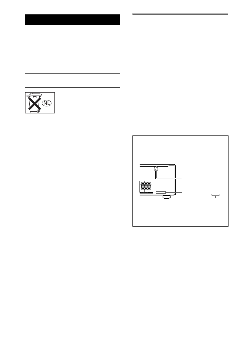
About area codes
The area code of the receiver you purchased is
shown on the lower portion of the rear panel (see
the illustration below).
LR
L
R
CENTER
FRONT
2-XXX-XXX-XX AA
Area code
Any differences in operation, according to the area
code, are clearly indicated in the text, for example,
“Models of area code AA only”.
This receiver incorporates Dolby* Digital and Pro
Logic Surround and the DTS** Digital Surround
System.
* Manufactured under license from Dolby
Laboratories.
“Dolby”, “Pro Logic” and the double-D symbol are
trademarks of Dolby Laboratories.
** “DTS” and “DTS Digital Surround” are registered
trademarks of Digital Theater Systems, Inc.
GB
2

Table of Contents
Getting Started
1: Check how to hookup your
components.......................................4
1a: Connecting components with
digital audio output jacks ...........6
1b: Connecting components with only
analog audio jacks......................8
2: Connecting the antennas .....................9
3: Connecting speakers .........................10
4: Connecting the AC power cord ........13
5: Setting up the speakers .....................15
6: Setting up the sub woofer .................17
7: Adjusting the speaker levels and
balance............................................17
— TEST TONE
Amplifier Operation
Selecting the component .......................18
Listening to FM/AM radio....................18
Presetting radio stations........................19
Changing the display.............................20
About the display..................................21
Enjoying Surround Sound
Using only the front speakers and sub
woofer.............................................22
— 2CH STEREO
Enjoying higher fidelity sound..............22
— AUTO FORMAT DIRECT
Selecting a sound field ..........................23
Other Operations
Naming preset stations and inputs........ 31
Using the Sleep Timer .......................... 31
Enjoying the lighting effects................. 32
Optional karaoke scoring system.......... 33
Operations Using the Remote
RM-AAU002
Before you use your remote.................. 34
Remote button description.................... 34
Changing the factory setting of an input
button.............................................. 37
Additional Information
Precautions............................................ 38
Troubleshooting.................................... 39
Specifications........................................ 41
List of button locations and reference
pages............................................... 43
Index ....................................... Back cover
Enjoying Karaoke
Using Karaoke ......................................25
Advanced karaoke settings ...................26
Advanced Adjustments and
Settings
Switching the audio input mode for digital
components.....................................28
— INPUT MODE
Customizing sound fields......................28
Advanced settings.................................30
GB
3

Getting Started
1: Check how to hookup your components
Steps 1a through 1b beginning on page 6 describe how to hook up your components to this receiver.
Before you begin, refer to “Connectable components” below for the pages which describe how to
connect each component.
After hooking up all your components, proceed to “2: Connecting the antennas” (page 9).
Connectable components
Component to be connected Page
DVD player
With digital audio output
With analog audio output only
Satellite tuner
With analog audio output only
Super Audio CD/CD player
With digital audio output
With analog audio output only
VCR 8
a)
Model with a DIGITAL OPTICAL OUTPUT or DIGITAL COAXIAL OUTPUT jack, etc.
b)
Model equipped only with AUDIO OUT L/R jacks, etc.
a)
b)
b)
a)
b)
6
8
8
7
8
GB
4
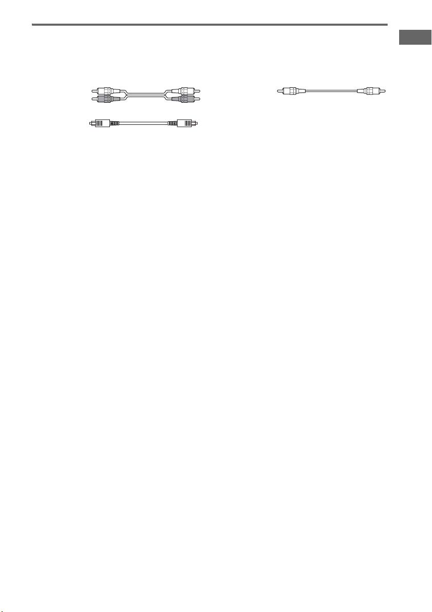
Required cords
The hookup diagrams on the subsequent pages assume the use of the following optional connection
cords (A to C) (not supplied unless indicated).
A Audio cord
White (L)
Red (R)
B Optical digital cord
Notes
• Turn off the power to all components before making any connections.
• Be sure to make connections firmly to avoid hum and noise.
• When connecting an audio cord, be sure to match the color-coded pins to the appropriate jacks on the components:
white (left, audio) to white; and red (right, audio) to red.
• When connecting optical digital cords, insert the cord plugs straight in until they click into place.
• Do not bend or tie optical digital cords.
C Coaxial digital cord (supplied)
Orange
Getting Started
GB
5
.
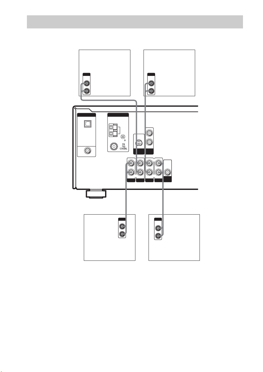
1a: Connecting components with digital audio output jacks
Hooking up a DVD player
For details on the required cords (A–C), see page 5.
DVD player
OUTPUT
AUDIO
OUT
OUTPUT
DIGITAL
COAXIAL
L
R
AC
DIGITAL
OPTICAL
SA-CD/
CD
IN
DVD IN
COAXIAL
ANTENNA
AM
SA-CD/CD
D-LIGHT
SYNC OUT
L
R
AUDIO IN AUDIO IN
DVD
MIC
OUT
AUDIO IN
VIDEO 2
L
R
L
R
AUDIO IN
VIDEO 1
AUDIO
OUT
SUB
WOOFER
GB
6
Hooking up a Super Audio CD/CD player
For details on the required cords (A–C), see page 5.
Getting Started
DIGITAL
OPTICAL
SA-CD/
CD
IN
DVD IN
COAXIAL
ANTENNA
AM
D-LIGHT
SYNC OUT
L
R
AUDIO IN AUDIO IN
SA-CD/CD
DVD
MIC
OUT
AUDIO IN
VIDEO 2
L
R
L
R
AUDIO IN
VIDEO 1
AUDIO
OUT
SUB
WOOFER
BA
DIGITAL
OPTICAL
OUT
OUTPUT
LINE
L
R
Super Audio CD/
CD player
Tip
All the digital audio jacks are compatible with 32 kHz, 44.1 kHz, 48 kHz and 96 kHz sampling frequencies.
Note
When you play a Super Audio CD disc on a Super Audio CD player, the sound is output only if you make the
connection to SA-CD/CD AUDIO IN jacks (analog input jack) on the receiver. Refer to the operating instructions
supplied with the Super Audio CD player.
GB
7
1b: Connecting components with only analog audio jacks
For details on the required cords (A–C), see page 5.
OUTPUT
DIGITAL
OPTICAL
SA-CD/
CD
IN
DVD IN
COAXIAL
AUDIO
OUT
L
R
DVD player
Satellite Tuner
or VCR
OUTPUT
AUDIO
OUT
L
A
R
A
ANTENNA
AM
L
R
MIC
D-LIGHT
OUT
SYNC OUT
L
L
R
AUDIO IN AUDIO IN
SA-CD/CD
DVD
AUDIO IN
VIDEO 2
R
AUDIO IN
VIDEO 1
AUDIO
OUT
SUB
WOOFER
AA
OUTPUT
LINE
L
R
OUTPUT
AUDIO
OUT
L
R
Super Audio CD/CD
player
GB
8
VCR
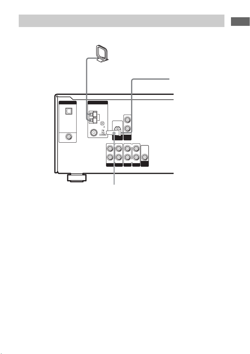
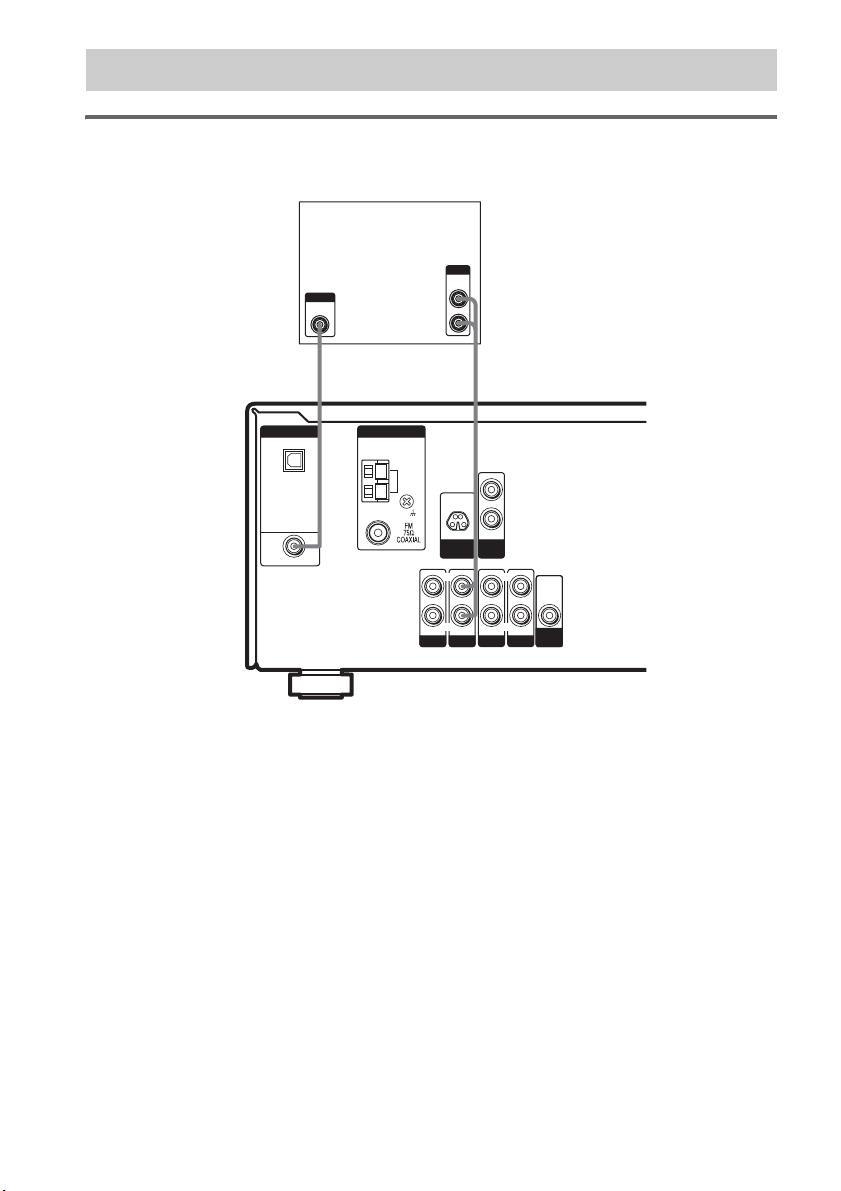
2: Connecting the antennas
Connect the supplied AM loop antenna and FM wire antenna.
AM loop antenna
(supplied)
Getting Started
FM wire antenna
(supplied)
DIGITAL
OPTICAL
SA-CD/
CD
IN
DVD IN
COAXIAL
ANTENNA
AM
D-LIGHT
SYNC OUT
L
R
AUDIO IN AUDIO IN
DVD
SA-CD/CD
MIC
OUT
AUDIO IN
VIDEO 2
L
R
L
R
AUDIO IN
VIDEO 1
AUDIO
OUT
SUB
WOOFER
*
* The shape of the connector varies depending on the area code.
Notes
• To prevent noise pickup, keep the AM loop antenna away from the receiver and other components.
• Be sure to fully extend the FM wire antenna.
• After connecting the FM wire antenna, keep it as horizontal as possible.
GB
9
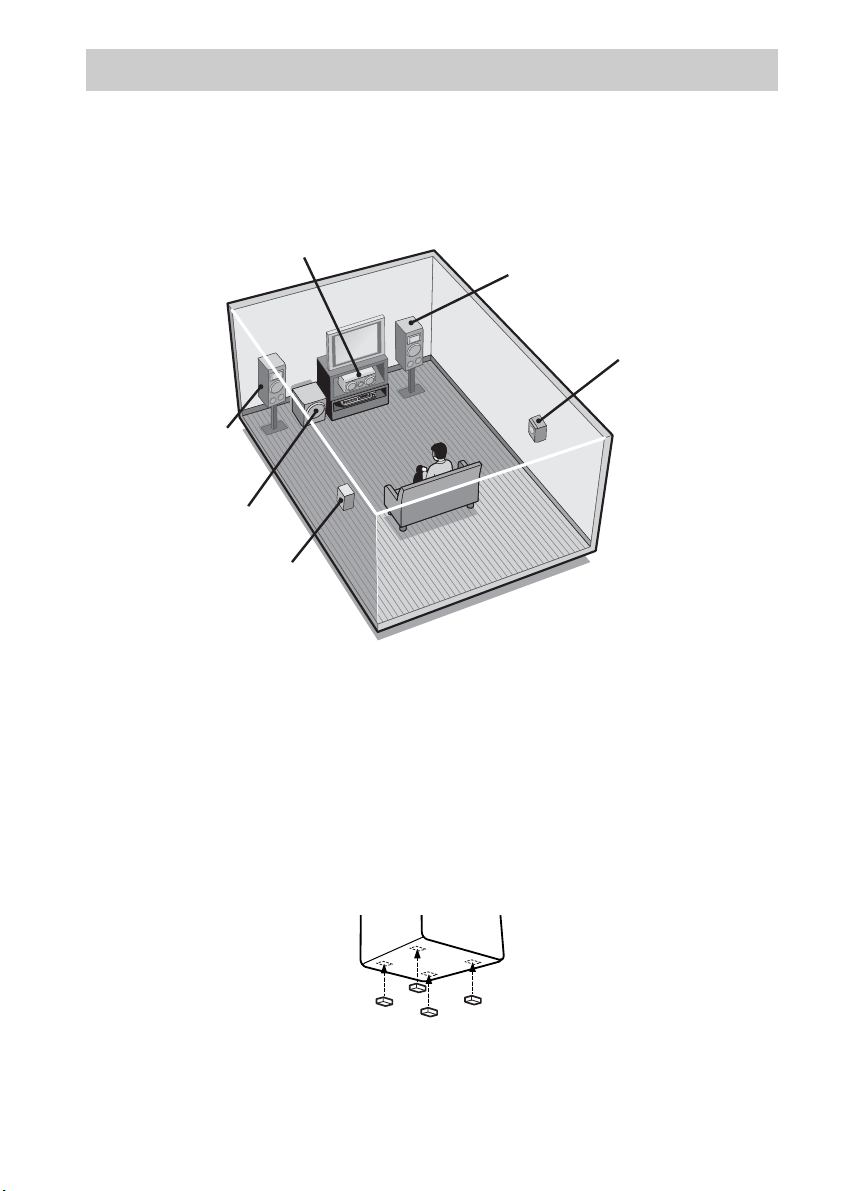
3: Connecting speakers
Connect your speakers to the receiver. This receiver allows you to use a 5.1 channel speaker system.
To fully enjoy theater-like multi channel surround sound requires five speakers (two front speakers, a
center speaker, and two surround speakers) and a sub woofer (5.1 channel).
Example of 5.1 channel speaker system configuration
Center speaker
Front speaker (Left)
Sub woofer
Surround speaker (Left)
Tips
• Since the sub woofer does not emit highly directional signals, you can place it wherever you want.
• For greater flexibility in the positioning of the surround speakers, use the optional WS-FV11 or WS-FV10D floor
stand (available only in certain countries).
• You can also install the front and surround speakers on the wall (page 12).
Note
Connect the long speaker cords to the surround speaker terminals and the short speaker cords to the front and center
speaker terminals.
Front speaker (Right)
Surround speaker (Right)
Attaching foot pads
To prevent speaker vibration or movement, attach the supplied foot pads to the speakers and sub woofer
as shown in the illustration below.
10
GB
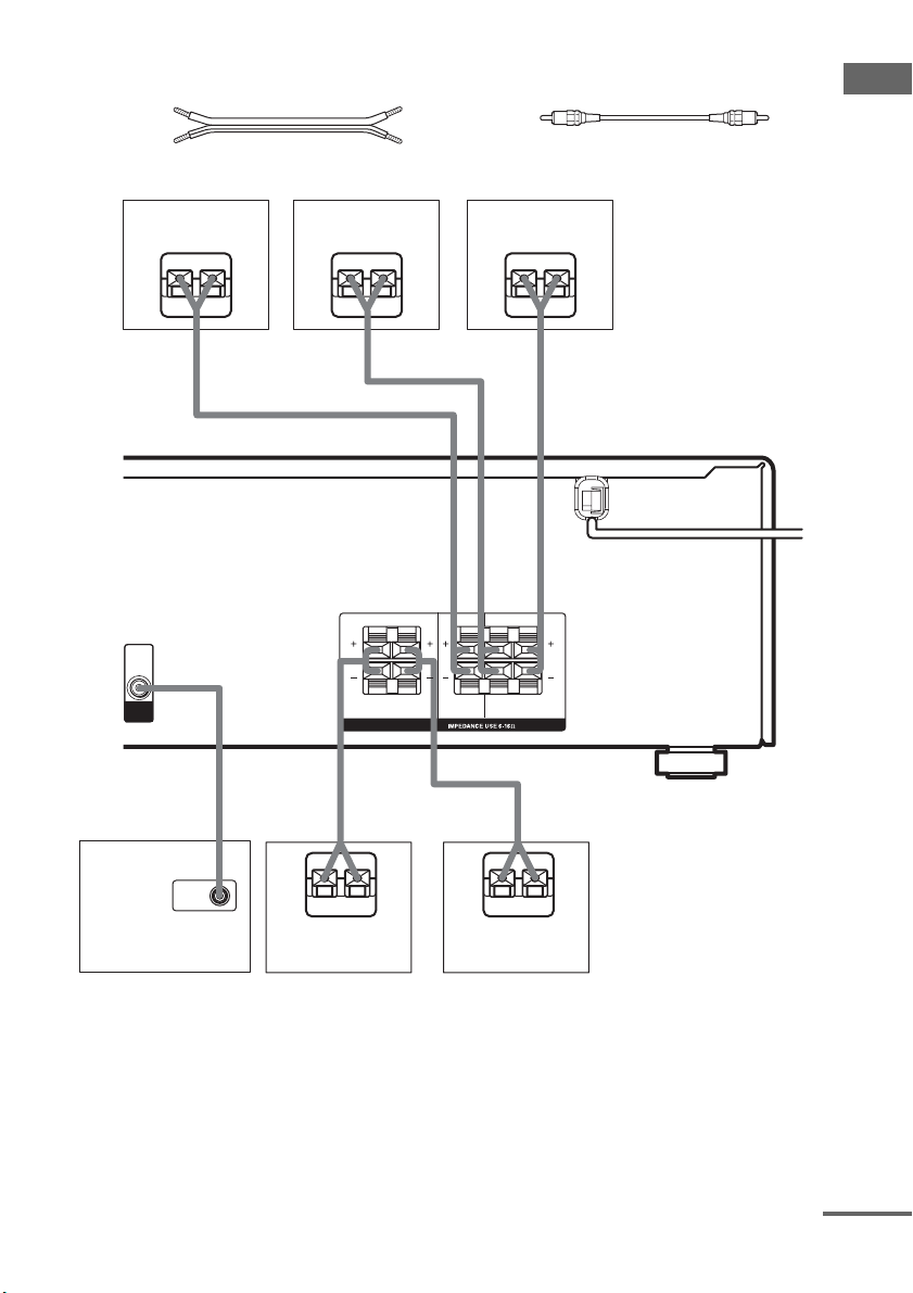
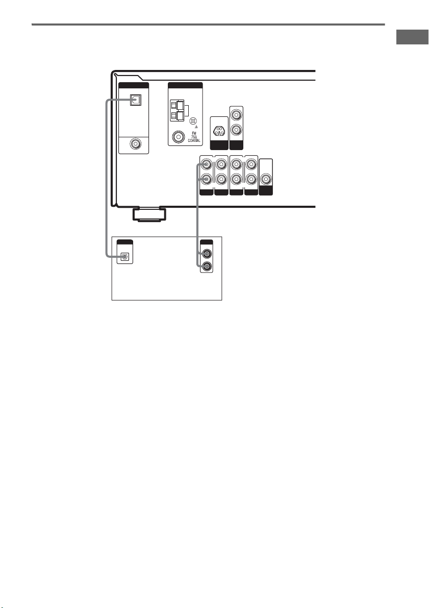
Required cords
A Speaker cords (supplied)
(+)
(–)
B Monaural audio cord (supplied)
Black
Getting Started
Center speaker
Ee
A
AUDIO
OUT
SUB
WOOFER
B
Front speaker
(Right)
Ee
A
LR
R
SPEAKERS
A
Front speaker
Ee
RL
CENTER
FRONTSURROUND
(Left)
A
LR
L
A
INPUT
Sub woofer
E
Surround speaker
(Right)
e
E
Surround speaker
(Left)
e
continued
11
GB
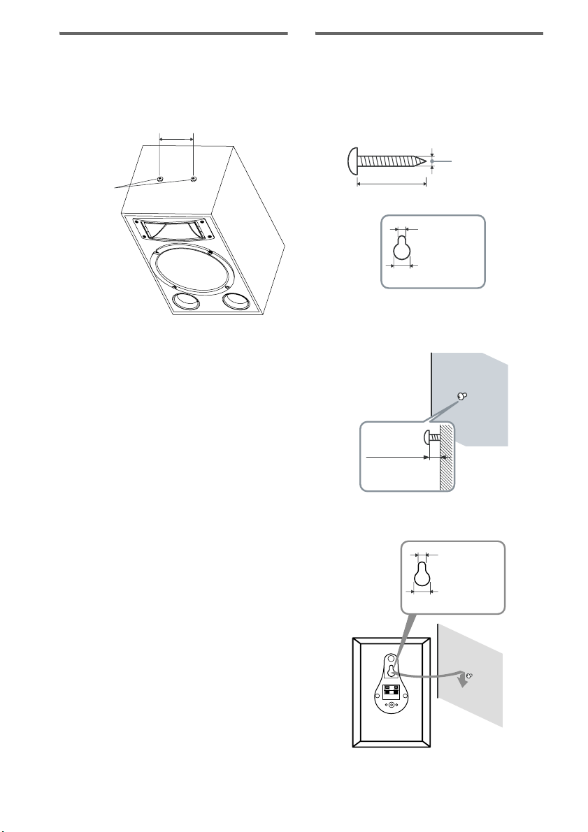
Installing the front speakers
on the ceiling/wall
You can hang the front speakers from the ceiling
or on a wall with hardware.
100 mm
Installing the surround
speakers on the wall
1 Prepare screws (not supplied) that are
suitable for the hole on the back of
each speaker. See the illustrations
below.
more than 4 mm
M8 screws
Attach the hanging hardware (not supplied)
on the top of the speakers.
Two M8 screws are already embedded in with
an interval of 100 mm on the top of the speaker.
Make sure the hanging hardware is match to the
interval of the screws on the top of the speakers.
Notes
• Use hanging hardware that is suitable for the ceiling
or wall material and strength. As a plaster board
ceiling is especially fragile, attach the hanging
hardware to a beam and fasten them to the ceiling
where reinforcement is applied.
• Contact the hanging hardware supplier or installer
regarding the ceiling, wall material and hanging
hardware to be used.
• Before installation, check the ceiling or wall to
ensure that it is strong enough to stand the weight of
the speakers. Sony is not responsible for accident or
damage caused by improper installation, insufficient
ceiling strength or improper hanging hardware
installation, natural calamity and etc.
more than 25 mm
4.6 mm
10 mm
Hole on the back of the speaker
2 Fasten the screws to the wall. The
screws should protrude 5 to 7 mm.
5 to 7 mm
3 Hang the speakers on the screws.
Hole on the back of the speaker
4.6 mm
10 mm
12
GB
Notes
• Use screws that are suitable for the wall material and
strength. As a plaster board wall is especially fragile,
attach the screws securely to a beam and fasten them
to the wall. Install the speakers on a vertical and flat
wall where reinforcement is applied.
• Contact a screw shop or installer regarding the wall
material or screws to be used.
• Sony is not responsible for accident or damage
caused by improper installation, insufficient wall
strength or improper screw installation, natural
calamity, etc.
4: Connecting the AC
Getting Started
power cord
Setting the voltage selector
for the receiver and sub
woofer
If your receiver and sub woofer has a voltage
selector on the rear panel, check that the voltage
selector is set to the local power supply voltage.
If not, use a screwdriver to set the selector to the
correct position before connecting the AC power
cord to a wall outlet.
Receiver
120V 220V 240V
VOLTAGE SELECTOR
Sub woofer
VOLTAGE SELECTOR
220V
120V
240V
continued
13
GB
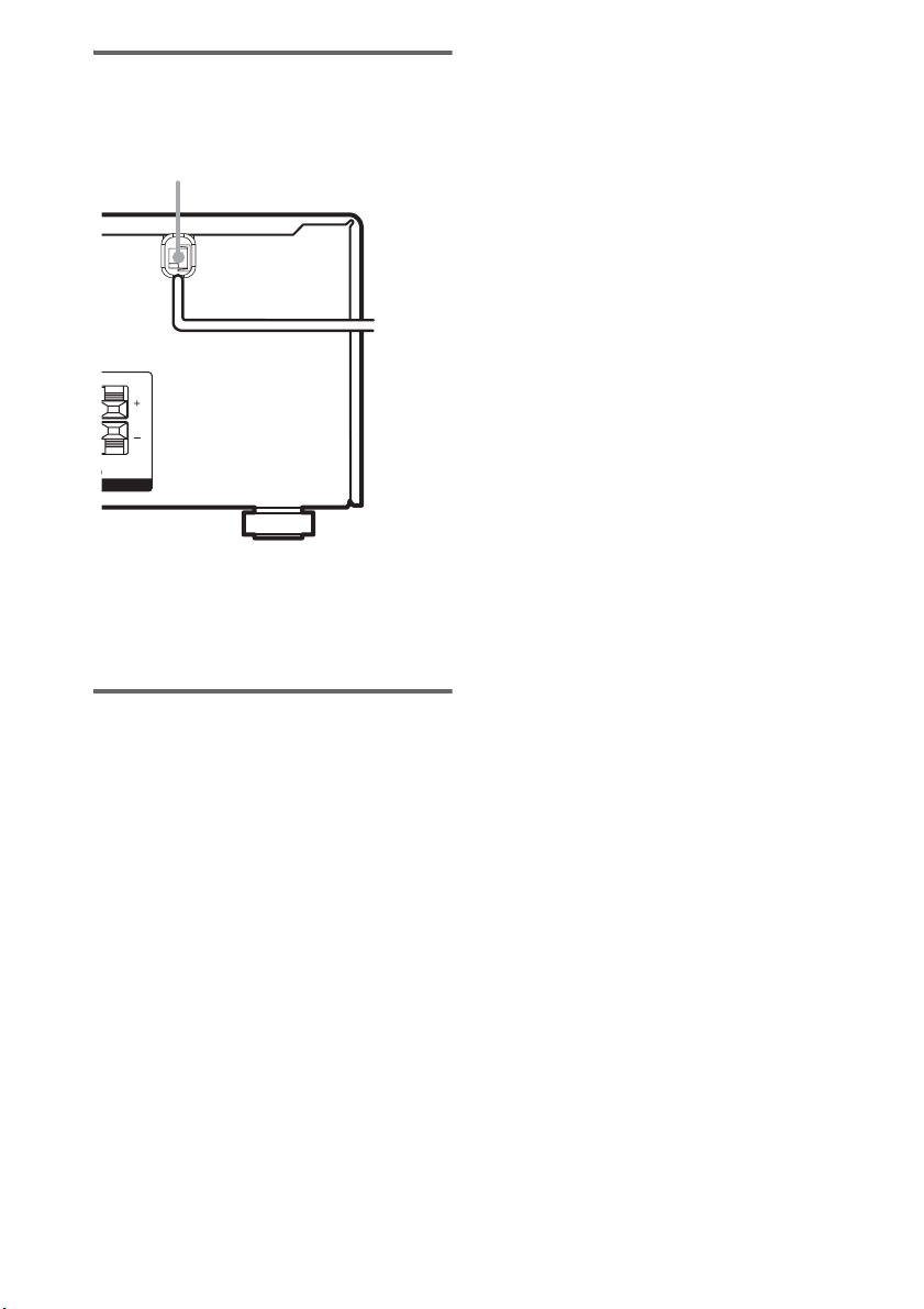
Connecting the AC power
cord
Connect the AC power cord to a wall outlet.
AC power cord
b
To a wall
L
L
NT
Note
Install this system so that the power cord can be
unplugged from the wall socket immediately in the
event of trouble.
outlet
3 Press MEMORY/ENTER.
“CLEARING” appears in the display for a
while, then “CLEARED” appears.
The following are reset to their factory
settings.
• All settings in the SETUP, KARAOKE,
LEVEL, CUSTOMIZE and TUNER
menus.
• The sound field memorized for each
input and preset station.
• All sound field parameters.
• All preset stations.
• All index names for inputs and preset
stations.
• MASTER VOLUME is set to “VOL
MIN”.
• MUSIC VOLUME is set to “MUSIC
0 dB”.
Performing initial setup
operations
Before using the receiver for the first time,
initialize the receiver by performing the
following procedure.
This procedure can also be used to return
settings you have made to their factory defaults.
Use the buttons on the receiver for the operation.
1 Press ?/1 to turn off the receiver.
2 Hold down ?/1 for 5 seconds.
“PUSH” and “ENTER” appears in the
display alternatingly.
GB
14
 Loading...