

Page 1
4-247-255-11(1)
Home Theater
System
Operating Instructions ________________________
Mode d’emploi______________________________
Manual de instrucciones ______________________
GB
FR
ES
HT-K250
©2003 Sony Corporation
Page 2
WARNING
To prevent fire or shock hazard, do not
expose the unit to rain or moisture.
To prevent fire, do not cover the ve ntilation of the
apparatus with news papers, table-cloths, curtains, etc.
And don’t place lighted candles on the apparatus.
To prevent fire or shock hazard, do not place objects
filled with liquids, such as vases, on the apparatus.
Don’t throw away the batt ery wi th
general house waste, dispose of it
correctly as chemical waste.
Do not install the appliance in a confined space, such
as a bookcase or built-in cabinet.
This system incorporates Dolby* Digital and Pro
Logic Surround and the DTS** Digital Surround
System.
* Manufactured under license from Dolby
Laboratories.
“Dolby”, “Pro Logic” and the double-D symbol are
trademarks of Dolby Labora t ories.
**“DTS” and “DTS Digital Surround” are registered
trademarks of Digital Thea ter Systems, Inc.
About This Manual
The instructions in this manual describe the
controls on the remote.
You can also use the controls on the control
center if they have the same or similar names as
those on the remote.
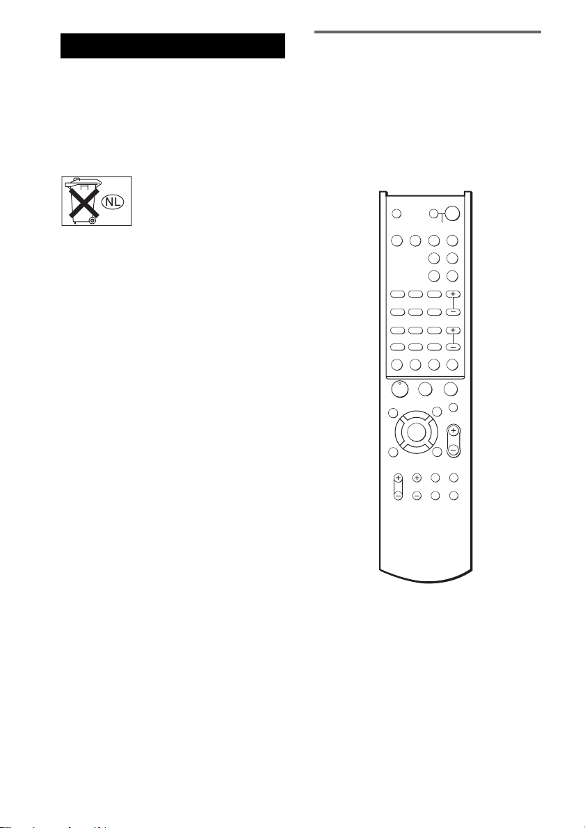
For the button location of remote, see “Using the
supplied remote to controlling the other
component” on page 23.
SYSTEM STANDBY
;
FM MODE
D.TUNING
SUBTITLE
MEMORY SHIFT
>
+
M
CLEAR
SEARCH MODE
X
A
F
ENTER
f
RETURN/EXIT
?/1
SLEEP
SAT TV
AUX TUNER
PL/PLII A.F.D.
SOUND
FIELD
PRESET/
CH/D.SKIP
-
x
MUTING
V MENU
MASTER
VOL
g
O
TV/
MAIN
VIDEO
MENU
WIDE TEST TONE
TV ?/1 AV ?/1
VIDEO DVD
AAC
BI-LING
123
AUDIO ANGLE
456
TIME SWAP JUMP
789
.
0/10 >10/11 ENTER/12
–
TUNING DISC ALT
m
ANT
N
TOP MENU/
GUIDE
G
DISPLAY
TV VOL TV CH
GB
2
Page 3

Table of Contents
Getting Started
1: Unpacking...........................................4
2: Connecting the control center and
subwoofer .........................................5
3: Connecting components with digital
audio output jacks.............................6
4: Connecting video components............8
5: Connecting the antennas.....................9
6: Placing speakers................................10
7: Connecting speakers .........................11
8: Attaching the stand ...........................13
9: Connecting the AC power cord ........14
Checking the connections and
settings............................................14
Listening to the Sound of
Connected Components
Selecting the component.......................16
About the indications in the display......17
Receiving FM/AM broadcasts..............18
Presetting radio stations ........................19
Enjoying Surround Sound
Selecting a sound field..........................21
GB
Other Operations/Settings
Using the Sleep Timer ..........................23
Using the supplied remote to controlling
the other component .......................23
Changing the factory setting of a function
button on the remote.......................25
Setting up the speakers..........................26
Customizing sound fields......................27
Additional Information
Precautions............................................29
Troubleshooting....................................30
Specifications........................................31
Glossary ................................................32
List of button locations and reference
pages...............................................34
Index .....................................................36
GB
3
Page 4
Getting Started
1: Unpacking
Check that the following items are supplied:
• Control center (1)
• Subwoofer (1)
• Micro satellite speakers (5)
• Control center stand and a screw (1 each)
• Remote commander (1)
• R6 (size AA) batteries (2)
• Speaker cords (long) (2)
• Speaker cords (short) (3)
• System cord (1)
• Optical digital cord (1)
• FM wire antenna (1)
• AM loop antenna (1)
• Speaker foot pads (20)
• Speaker sticker (1)
• Speaker adaptor for wall use and a screw (5
each)
• This Operating Instructions (1)
• Speaker installation guide (1)
• Do not expose the remote sensor of the c ontrol center
to direct sunlight or lighting apparatuses. Doing so
may cause a malfunction.
• If you do not use the remote for an extended period
of time, remove the batteries to avoid possible
damage from battery leakage and corrosion.
• Turn off the power to all components before making
any connections.
• Be sure to make connections firmly to avoid hum and
noise.
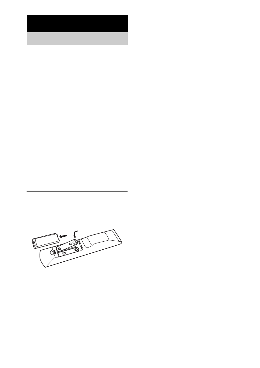
Inserting batteries into the
remote
Insert two R6 (size AA) batteries with the + and
– properly oriented in the battery compartment.
Tip
Under normal conditions, the batteries should last for
about 6 months. When the remote no longer operates
the control center, replace both batteries with new
ones.
Notes
• Do not leave the remote in an extr emely hot or humid
place.
• Do not use a new battery with an old one.
GB
4
Page 5
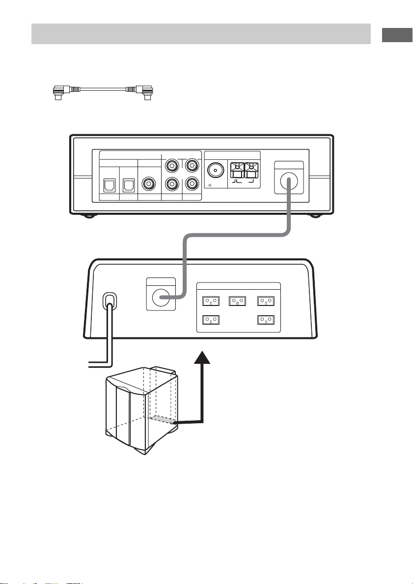
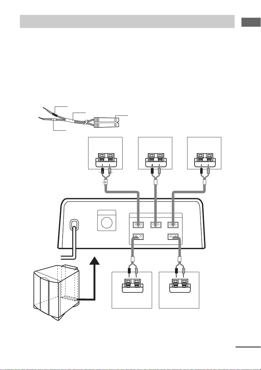
2: Connecting the control center and subwoofer
Required cords
System cord (supplied)
Control center
Getting Started
INPUT
DVD
Subwoofer
DIGITAL
COAXIALOPTICAL
SAT AUX
L
R
VIDEO
CONTROL
ANALOG
TV
FM
COAXIAL
75
FRONT R
SURR R
ANTENNA
U
SPEAKERS
CENTER
CONTROL
AM
FRONT L
SURR L
Note
Be sure to disconnect the AC power cord before connecting or disconnecting the system cord.
If you disconnect the system cord with the AC power cord connected, the system may not turn on. In this case,
disconnect the AC power cord, reconnect the system cord, then connect the AC power cord and turn on the system
again.
GB
5
Page 6
.
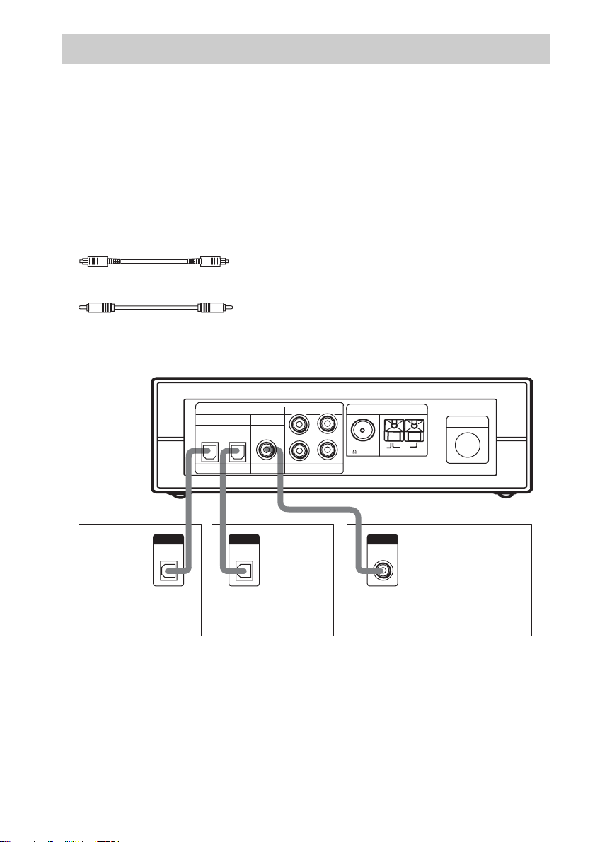
3: Connecting components with digital audio output jacks
Connect the digital audio output jacks of your DVD player or other component (“Play Station 2”, CD
player, MD deck, satellite tuner, etc.) to the control center’s digital audio input jacks to bring the multi
channel surround sound of a movie theater into your home.
Connect the video output jacks of your DVD player or “Play Station 2” to the video input jacks of your
TV.
Note
You cannot input the video signal to this system. When you connect video components (VCR, TV, etc.), connect the
video output jack of the video component to the video input jack of your TV.
Required cords
Optical digital cord (supplied)
Coaxial digital cord (not supplied)
Control center
OUTPUT
OPTICAL
OUT
DVD player or
“Play Station 2”
DIGITAL
INPUT
DVD SAT AUX
OUTPUT
OPTICAL
OUT
COAXIALOPTICAL
Satellite tuner
L
R
VIDEO
ANALOG
ANTENNA
FM
U
COAXIAL
75
TV
OUTPUT
COAXIAL
OUT
Other digital audio/video
components (CD player,
MD deck, etc.)
Tip
The digital input jacks are compatible with 32 kHz, 44.1 kHz, and 48 kHz sampling frequencies.
GB
6
CONTROL
AM
Page 7

Setting for when you use Sony DVD player or “Play Station 2”
When you connect DVD player or “Play Station 2” as shown on the previous page, perform the
following settings on each component. For details, refer to the operating instructions supplied with each
component.
DVD player
1 Select “AUDIO SETUP” in the setup
display.
2 Set “AUDIO DRC” to “WIDE RANGE”.
3 Set “DIGITAL OUT” to “ON”.
4 Set “DOLBY DIGITAL” to “DOLBY
DIGITAL”.
5 Set “DTS” to “ON”.
“Play Station 2” is a trademark of Sony Computer Entertainment.
“Play Station 2”
1 Select “AUDIO SETTING” in the setup
display.
2 Select “AUDIO DIGITAL OUTPUT”.
3 Set “OPTICAL DIGITAL OUTPUT” to
“ON”.
4 Set “DOLBY DIGITAL” to “ON”.
5 Set “DTS” to “ON”.
Getting Started
GB
7
Page 8
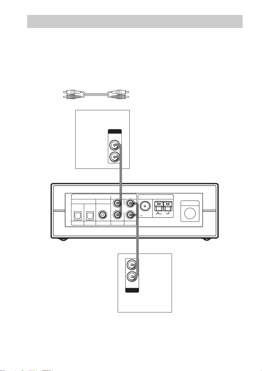
4: Connecting video components
Required cords
Audio cord (not supplied)
When connecting a cord, be sure to match the color-coded pins to the appropriate jacks on the
components; white (left) to white; and red (right) to red.
Note
You cannot input the video signal to this system. When you connect video components (VCR, TV, etc.), connect the
video output jack of the video component to the video input jack of your TV.
White (L)
Red (R)
VCR
OUTPUT
AUDIO
OUT
L
R
Control center
DIGITAL
INPUT
DVD SAT AUX
COAXIALOPTICAL
ANALOG
L
R
VIDEO
TV
AUDIO
OUT
OUTPUT
75
L
R
ANTENNA
FM
COAXIAL
CONTROL
AM
U
TV monitor
GB
8
Page 9
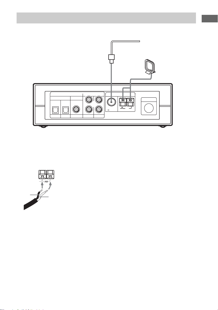
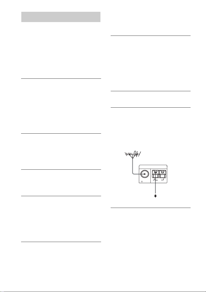
5: Connecting the antennas
Connect the supplied AM loop antenna and FM wire antenna.
FM wire antenna
(supplied)
AM loop antenna
(supplied)
Getting Started
DIGITAL
INPUT
DVD SAT AUX
COAXIALOPTICAL
L
R
VIDEO
ANALOG
ANTENNA
CONTROL
FM
AM
U
COAXIAL
75
TV
Notes on antenna hookups
• To prevent noise pickup, keep the AM loop antenna away from the receiver and other components.
• Be sure to fully extend the FM wire antenna.
• After connecting the FM wire antenna, ke ep it as horizontal as possible.
• When you connect supplied AM antenna to the component, connect the black cord (B) to U jack, and the white
cord (A) to the other jack.
GB
9
Page 10
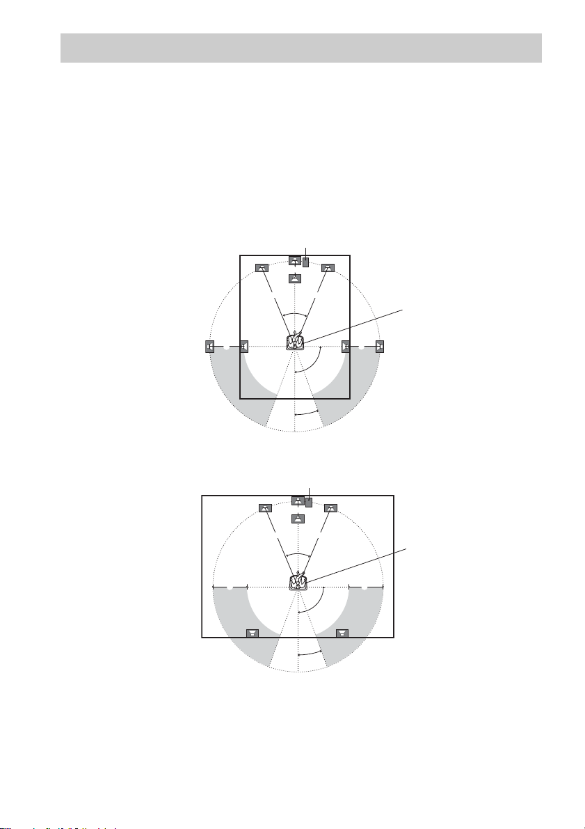
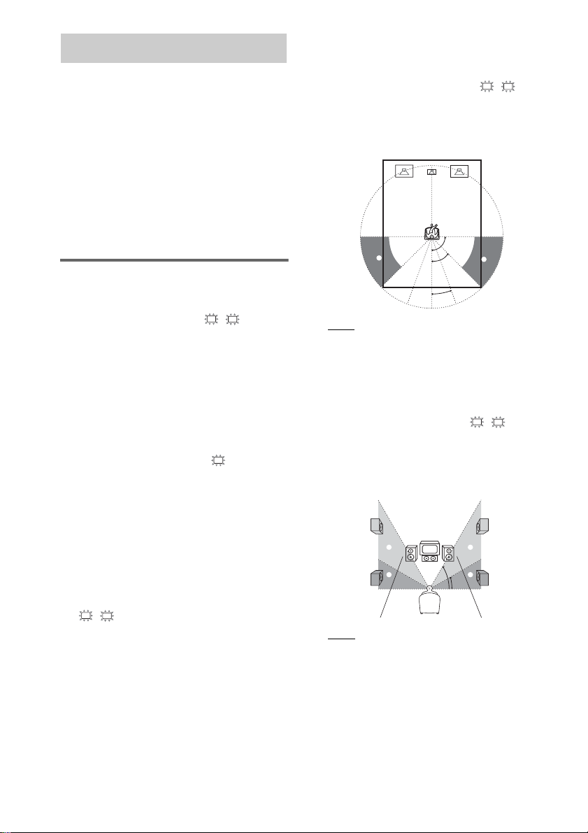
6: Placing speakers
To fully enjoy surround sound, configure your speakers as below.
• Place the front speaker in a location 1 to 7 meters from the listening position (A).
• You can enjoy a higher quality sound effect if you place the center speaker from a distance equal to
the front speaker distance (A) to a distance 1.5 meters closer to your listening position (B).
• You can enjoy a higher quality sound effect if you place the surround speakers from a distance equal
to the front speaker distance (A) to a distance 4.5 meters closer to your listening position (C).
• Place the subwoofer at the same distance from the listening position as the front speaker (left or
right).
When placing surround speakers to your side
Subwoofer
B
A A
45˚
CC
90˚
20˚
Listening position
10
When placing surround speakers behind you
Subwoofer
B
AA
45˚
CC
90˚
20˚
Note
Listening position
Do not place the center speaker and surround speakers farther away from the l i stening position than the front
speakers.
GB
Page 11
7: Connecting speakers
Be sure to place the speakers before making connections.
On the subwoofer
Connect the speaker cords by matching the color of speaker plugs and speaker jacks.
On the satellite speakers
Stick the supplied speaker stickers (“FRONT L” etc., 5 colors) on the satellite speakers and connect the
speaker cords by matching the color of speaker stickers and the color tubes on the speaker cords.
Speaker cords (supplied)
Connect the cord with a black tube to the (–) jack.
(–)
(+)
Black tube
Red tube
Color tube
Speaker plug
Getting Started
Front speaker
(R)
–
Black tube (–) Red tube (+)
Color tube
Subwoofer
Red Green White
CONTROL
Surround speaker
+
Gray
Center speaker Front speaker
+
FRONT LCENTER
SURR L
–
Surround speaker
(L)
–
FRONT R
SURR R
(R)
–
SPEAKERS
+
Blue
(L)
–
+
+
continued
11
GB
Page 12
To avoid short-circuiting the
speakers
Short-circuiting may damage the speakers and
cause a malfunction.
Make sure the stripped ends of each
speaker cord does not touch the stripped
end of another speaker cord.
Examples of poor conditions of the speaker
cord
Stabilizing speakers
To prevent speaker vibration or movement while
listening, attach the supplied foot pads at the
bottom of the speakers. If you are using the
speaker stand (not supplied), you do not need to
attach them.
Installing the satellite
speakers on the wall
Fasten the screws (not supplied) to the wall. The
screws should protrude by 5 to 6 mm.
5 to 6 mm
Attach the speaker adaptor for wall use
(supplied) with the screw (supplied), then hang
the satellite speakers on the screws.
4.2 mm
9.2 mm
12
Using speaker stand (not
supplied)
When using separately sold speaker stand
(WS-FV10D, WS-WV10D), you can easily
configure your speaker layout.
WS-FV10D
GB
WS-WV10D
(Wall use)
speaker adaptor for wall use
Notes
• Use the screws that matc hes the wall material and
strength.
• Install the satellite speakers on a vertical and fla t wall
where reinforcement is applied. Do not install the
satellite speakers if the wall is not vertical, flat or
strong enough.
• Contact a screw shop or installer regarding the wall
material or screws to be used.
• Sony will refrain from any responsibility on the
accident or damage caused by improper installation,
lack of durability of the wall or screws improper
operation, natural calamity, etc.
Page 13
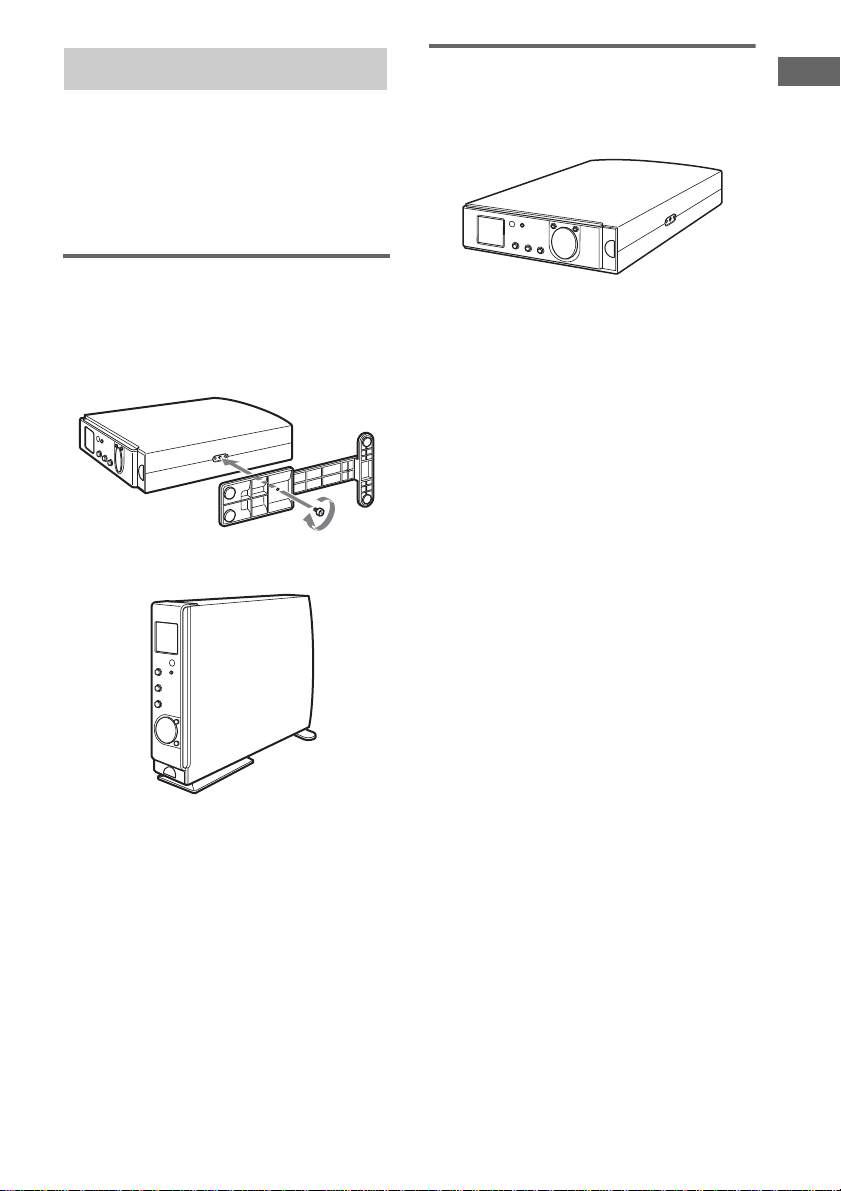
8: Attaching the stand
You can use the control center in an upright
position or laid flat. When using in an upright
position, be sure to attach the supplied control
center stand. Besides, you can change the item
layout in the display according to the layout of
the control center (page 18).
Using the control center in
the upright position
Attach the stand to the screw hole on the
side of the control center using the
supplied screw.
m
Using the control center laid
flat
Place the control center flat on a level
surface.
Getting Started
Notes
• Be sure to attach the stand when using the control
center in the upright position.
• Use the supplied stand only when you use the control
center in an upright position. Do not attach the stand
when you use the control center laid flat.
• To move the control center, hold the control center
itself. If you hold the stand, it may break.
• Do not use the control center in an upright position
without attaching the stand. If you do not attach the
stand, the control center will be unstable and may fall
over.
• Be sure to keep the screws out of reach o f the
children.
13
GB
Page 14
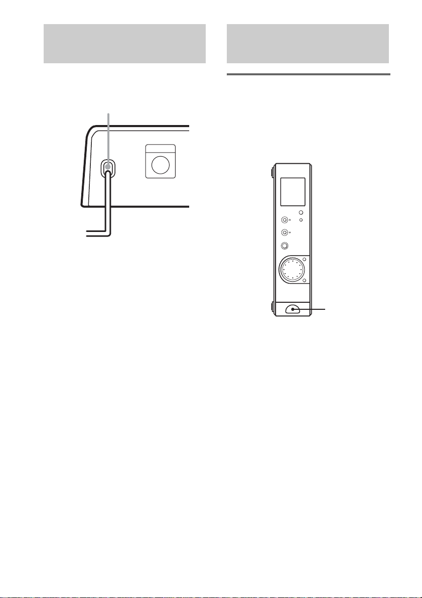
9: Connecting the AC
Checking the connections
power cord
After connecting the components, connect the
AC power cord of the subwoofer to a wall outlet.
AC power cord
Subwoofer
CONTROL
b
To a wall outlet
and settings
Performing initial setup
operations
Before using the system for the first time,
initialize the system by performing the
following procedure.
This procedure can also be used to return
settings you have made to their factory defaults.
?/1
1 Press ?/1 to turn off the system.
2 Hold down ?/1 until “INITIAL” appears
in the display.
The current input name appears.
The following are reset to their factory
settings.
• All settings in the SET UP and LEVEL
and EFFECT menus.
• The sound field memorized for each
input.
• All preset stations.
Besides, the volume is set to minimum
(MIN).
14
GB
Page 15
Checking if the sound comes
from all speakers
.
X
ENTER
F
f
AV MENU
O
RETURN/EXIT
TV/
VIDEO
WIDE TEST TONE
x
MUTING
MASTER
VOL
MAIN
MENU
MASTER VOL
TEST TONE
N
TOP MENU/
GUIDE
Gg
DISPLAY
TV VOL TV CH
1 Press MASTER VOL +.
(Optimal volume level: Between 20–30.)
2 Press TEST TONE.
You will hear the test tone from each
speaker in sequence.
Front (left) t Center t Front (right) t
Surround (right) t Surround (left) t
Subwoofer
While outputting the test tone, if no sound
comes from the speakers or the test tone is
output from the speaker whose name is not
displayed in the display, there is a shortcircuiting or the connection is wrong. In this
case, check the speaker connection again.
3 Press TEST TONE again to turn off the
test tone.
Getting Started
15
GB
Page 16

Listening to the Sound of Connected
Components
Selecting the component
You can select Sony components only.
1 Press one of the function buttons.
When using the control center, press
INPUT SELECTOR repeatedly.
To select Press
DVD player or “Play Station 2”DVD
Satellite tuner SAT
An audio/video component
(CD player, MD deck, etc.)
VCR VIDEO
TV TV
Tuner TUNER
AUX
2 Turn on the component and start
playback.
When you select a component which is also
connected to the TV (such as VCR or DVD
player), turn on the TV and set the TV’s
video input to match the component you
selected.
3 Press MASTER VOL +/– to adjust the
volume.
When using the control center, rotate VOL/
PRESET TUNING.
To mute the sound
Press MUTING.
Playing a DVD on the
connected DVD player (not
supplied)
When you connect a DVD player or “Play
Station 2” and a TV, you can enjoy DVDs.
1 Press DVD.
2 Select the video input for your TV.
For details, refer to the instructions supplied
with your TV.
3 Place a DVD in your DVD player or
“Play Station 2”.
4 Start playing the DVD.
16
GB
Page 17
About the indications in the display
5
21
You can change the item layout in the display according to the layout of the control center (page 18).
Vertical display Horizontal display
Listening to the Sound of Connected Components
2
1
FM
STEREO
AM
MONO
L C R
SW
L.F.E.
SL S SR
DIGITAL
PLII
0
A AM: Lights up when an AM station is tuned
in.
B FM: Lights up when an FM station is tuned in.
C MONO: Lights up when receiving an FM
station in monaural mode.
D STEREO: Lights up when receiving an FM
station in stereo mode.
E : Lights up when the disc being
L.F.E.
played back contains the LFE (Low Frequency
Effect) channel and when the sound of the
LFE channel signal is actually being
reproduced.
F MEMORY: Lights up when presetting radio
station.
G DTS: Lights up when the system is decoding
DTS signals.
H ; DIGITAL: Lights up when the system is
decoding Dolby Digital signals.
I ; PL (II): Lights up when the system applies
Pro Logic or Pro Logic (II) processing.
89
6
MHz
KHz
MEMORY
DTS
7
1
2
5
43
6
2
1
FM
AM
J Playback channel indicators: The letters
light up to indicate the channels being played
back.
L (Front Left), R (Front Right), C (Center
(monaural)), SL (Surround Left), SR
(Surround Right), S (Surround (monaural or
the surround components obtained by Pro
Logic processing)), SW (Subwoofer)
The boxes around the letters light up to
indicate the speakers used to playback the
channels.
Example:
Recording format (Front/Surround): 3/2
Sound Field: A.F.D. AUTO.
43
STEREO
MONO
0
7
L C R
SW
SL SR
MEMORY
L C R
SW
SL S SR
DTS
DIGITAL
PLII
9
MHz
KHz
L.F.E.
8
continued
17
GB
Page 18

Switching the display
(vertical/horizontal)
You can switch the display as follows depending
on how you place the control center (page 13).
Press DISPLAY POSITION repeatedly.
Each time you press the button, the display
layout changes.
Receiving FM/AM
broadcasts
You can receive FM/AM broadcasts with the
tuner in this system.
Before receiving broadcasts, make sure you
have connected FM and AM antennas to the
receiver (page 9).
Tip
You can tune in the station in 50 kHz steps for
FM band and 9 kHz steps for AM band.
Manual tuning
Use the numeric buttons on the remote to input
the frequency of the station.
1 Press TUNER.
You can also use INPUT SELECTOR on
the control center.
2 Press TUNER repeatedly to select FM
or AM band.
3 Press D.TUNING.
The ALT button lights up.
4 Press the numeric buttons to input the
frequency of the station.
Example 1: FM 102.50 MHz
Press 1 t 0 t 2 t 5 t 0.
Example 2: AM 1,350 kHz
Press 1 t 3 t 5 t 0.
If you have tuned in an AM station, adjust
the direction of the AM loop antenna for
optimum reception.
If you cannot tune in a station
and the entered numbers flash
Make sure you have entered the right frequency.
If not, press ALT to turn off the display, then
repeat steps 3 and 4 again. If the entered
numbers still flash, the frequency is not used in
your area.
Tips
• If you do not remember the precise f req u en cy, pr es s
TUNING + or TUNING – after entering the value
close to the frequency you w ant. The receiver
automatically tunes in the station you want. If the
18
GB
Page 19

frequency seems to be higher than the entered value,
press TUNING +, and if the frequency seems to be
lower than the entered value, press TUNING –.
• If “STEREO” flashes in the display and the FM
stereo reception is poor, press FM MODE to select
“MONO”. You will not be able to enjoy the stereo
effect, but the sound will be less distorted.
Note
If “STEREO” does not appear at all when an FM
broadcast is received normally, press FM MODE to
turn on the “STEREO” indication.
Automatic tuning
If you don’t know the frequency of the station
you want, you can let the receiver scan all
available stations in your area.
1 Press TUNER.
You can also use INPUT SELECTOR on
the control center.
2 Press TUNER repeatedly to select FM
or AM band.
3 Press TUNING + or TUNING –.
Press TUNING + to scan from low to high;
press TUNING – to scan from high to low.
The receiver stops scanning whenever a
station is received.
4 To continue scanning, press TUNING +
or TUNING – again.
If the FM stereo reception is poor
Press FM MODE to select monaural mode.
If “STEREO” flashes in the display and the FM
stereo reception is poor, the sound will be less
distorted in the monaural mode.
Presetting radio stations
Up to 30 FM or AM stations can be preset.
You can tune in any of the stations you preset
directly.
Presetting radio stations
1 Press TUNER.
You can also use INPUT SELECTOR on
the control center.
2 Tune in the station that you want to
preset using Manual Tuning (page 18)
or Automatic Tuning (page 19).
3 Press MEMORY.
The ALT button lights up.
“MEMORY” appears in the display for a
few seconds. Do step 4 before it goes out.
4 Press SHIFT to select the memory page
(A, B or C) and press numeric buttons
to select a preset number.
The station is stored to the preset number.
If “MEMORY” goes out before you press
the preset number, start again from step 3.
5 Repeat steps 2 to 4 to preset another
station.
Tuning to preset stations
On the control center
1 Press VOL/PRESET TUNING.
The preset number flashes.
2 Turn VOL/PRESET TUNING to select the
preset number.
Each time you turn VOL/PRESET TUNING,
the receiver tunes in one preset station at a
time, in the corresponding order and direction
as follows:
tA1yA2y...yA0yB1yB2y...yB0T
Listening to the Sound of Connected Components
tC0y...yC2yC1T
continued
19
GB
Page 20

On the remote
1 Press TUNER.
2 Press PRESET/CH/D.SKIP + or PRESET/
CH/D.SKIP – to select the preset number.
Tuning directly by entering the
preset number
1 Press TUNER.
2 Press ALT.
“ALT” appears in the display.
3 Press SHIFT to select the memory page (A,
B or C) and press numeric buttons to select
a preset number.
20
GB
Page 21

Enjoying Surround Sound
Selecting a sound field
You can take advantage of surround sound
simply by selecting one of the system’s preprogrammed sound fields. They bring the
exciting and powerful sound of movie theaters
and concert halls into your home.
Press SOUND FIELD +/– repeatedly to
select the sound field you want.
The selected sound field appears in the display.
Sound field list Display
A.F.D. AUTO AFD AUTO
A.F.D. Pro Logic DOLBY PL
A.F.D. PL II MOVIE PLII MOV
A.F.D. PL II MUSIC PLII MUS
CINEMA STUDIO EX A DCS C.S.EX A
CINEMA STUDIO EX B DCS C.S.EX B
CINEMA STUDIO EX C DCS C.S.EX C
HALL HALL
JAZZ JAZZ
LIVE CONCERT CONCERT
GAME GAME
About DCS (Digital Cinema
Sound)
Sound fields with DCS marks use DCS
technology.
DCS is the concept name of the surround
technology for home theater developed by Sony.
DCS uses the DSP (Digital Signal Processor)
technology to reproduce the sound
characteristics of an actual cinema cutting studio
in Hollywood.
When played at home, DCS will create a
powerful theater effect that mimics the artistic
combination of sound and action as envisioned
by the movie director.
Enjoying movies using the
CINEMA STUDIO EX modes
CINEMA STUDIO EX modes are suitable for
watching motion picture DVDs (etc.), with
multi channel surround effects. You can
reproduce the sound characteristics of Sony
Pictures Entertainment’s dubbing studio in your
home.
There are three CINEMA STUDIO EX modes.
x CINEMA STUDIO EX A DCS
Reproduces the sound characteristics of the
Sony Pictures Entertainment “Cary Grant
Theater” cinema production studio. This is a
standard mode, great for watching most any type
of movies.
x CINEMA STUDIO EX B DCS
Reproduces the sound characteristics of the
Sony Pictures Entertainment “Kim Novak
Theater” cinema production studio. This mode
is ideal for watching science-fiction or action
movies with lots of sound effects.
x CINEMA STUDIO EX C DCS
Reproduces the sound characteristics of the
Sony Pictures Entertainment scoring stage. This
mode is ideal for watching musicals or films
where orchestra music is featured in the
soundtrack.
About CINEMA STUDIO EX modes
The CINEMA STUDIO EX modes consist of
the following three elements.
• Virtual Multi Dimension
Creates 5 sets of virtual speakers from a single
pair of actual surround speakers.
• Screen Depth Matching
Creates the sensation that the sound is coming
from inside the screen like in theaters.
• Cinema Studio Reverberation
Reproduces the type of reverberation found in
theaters.
The CINEMA STUDIO EX modes integrate
these three elements simultaneously.
Tip
You can identify the encoding format of DVD
software, etc. by looking at the logo on the package.
– : Dolby Digital discs
– : Dolby Surround encoded programs
– : DTS Digital Surround encoded programs
Enjoying Surround Sound
continued
21
GB
Page 22

Enjoying Dolby Pro Logic (II)
This function lets you specify the type of
decoding for 2 channel audio sources.
This system can reproduce 2 channel sound in 4
channels through Dolby Pro Logic; or 5
channels through Dolby Pro Logic II.
x A.F.D. Pro Logic
Dealing with Dolby Pro Logic. Sources
recorded in 2 channels are decoded and played
back in 4 channels.
x A.F.D. PL II MOVIE
Dealing with DOLBY PRO LOGI C II MOVI E.
This is ideal for playback of Dolby Surround
encoded movies. Dubbed or old movies can be
played back in 5 channels.
x A.F.D. PL II MUSIC
Dealing with DOLBY PRO LOGIC II MUSIC.
This is ideal for playback of normal stereo
sources such as CDs.
Note
Dolby Pro Logic and Dolby Pro Logic II do not work
for DTS signals.
Detecting the type of audio
signal automatically
x A.F.D. AUTO
A.F.D. (Auto Format Direct) function
automatically detects the type of audio signal
being input (Dolby Digital, DTS, or standard 2
channel stereo) and performs the proper
decoding if necessary. This mode presents the
sound as it was recorded/encoded, without
adding any effects (ex. reverberation).
Other sound fields
x HALL
Reproduces the acoustics of a rectangular
concert hall.
x JAZZ
Reproduces the acoustics of a jazz club.
x LIVE CONCERT
Reproduces the acoustics of a 300-seat live
house.
x GAME
Obtains maximum audio impact from TV game
software.
Making the low-level sound
clear (DOLBY DRC)
When you listen to DVDs at low volume levels,
you can compress the dynamic range and finely
adjust for low-level sound. This function works
only for DVDs compatible with Dolby DRC*
(audio DRC).
* Dolby DRC: Dolby Dynamic Range
Compressor
1 Press MAIN MENU repeatedly to select
“LEVEL”.
2 Move the V/v/B/b button up or down
to select “DRC”.
3 Move the V/v/B/b button to left or
right to select “STD” or “MAX”.
If you select “STD”, the dynamic range is
compressed as intended by the recording
engineer.
If you select “MAX”, the dynamic range is
compressed dramatically.
To turn off the DOLBY DRC, select
“OFF”.
Tip
Dynamic range compressor lets you compress the
dynamic range of the soundtrack based on the dynamic
range information included in the Dolby Digital signal.
“STD” is standard compression, but because many
sources have only light compression, we recommend
using the “MAX” setting. This grea tly comp resses the
dynamic range and lets you view movies late at night
at low volumes. Unlike analog limiters, the levels are
predetermined and provide a very natural compression.
Note
Dynamic range compression is possible with Dolby
Digital sources only.
22
GB
Page 23
Other Operations/Settings
Using the Sleep Timer
You can set the system to turn off automatically
at a specified time.
Press ALT, then press SLEEP.
Each time you press SLEEP, the display changes
cyclically as follows.
2:00:00 t 1:30:00 t 1:00:00 t 0:30:00 t
OFF
While using Sleep Timer, the display dims.
Tip
To check the remaining time before the system turns
off, press SLEEP after pressing ALT. The remaining
time appears in the display.
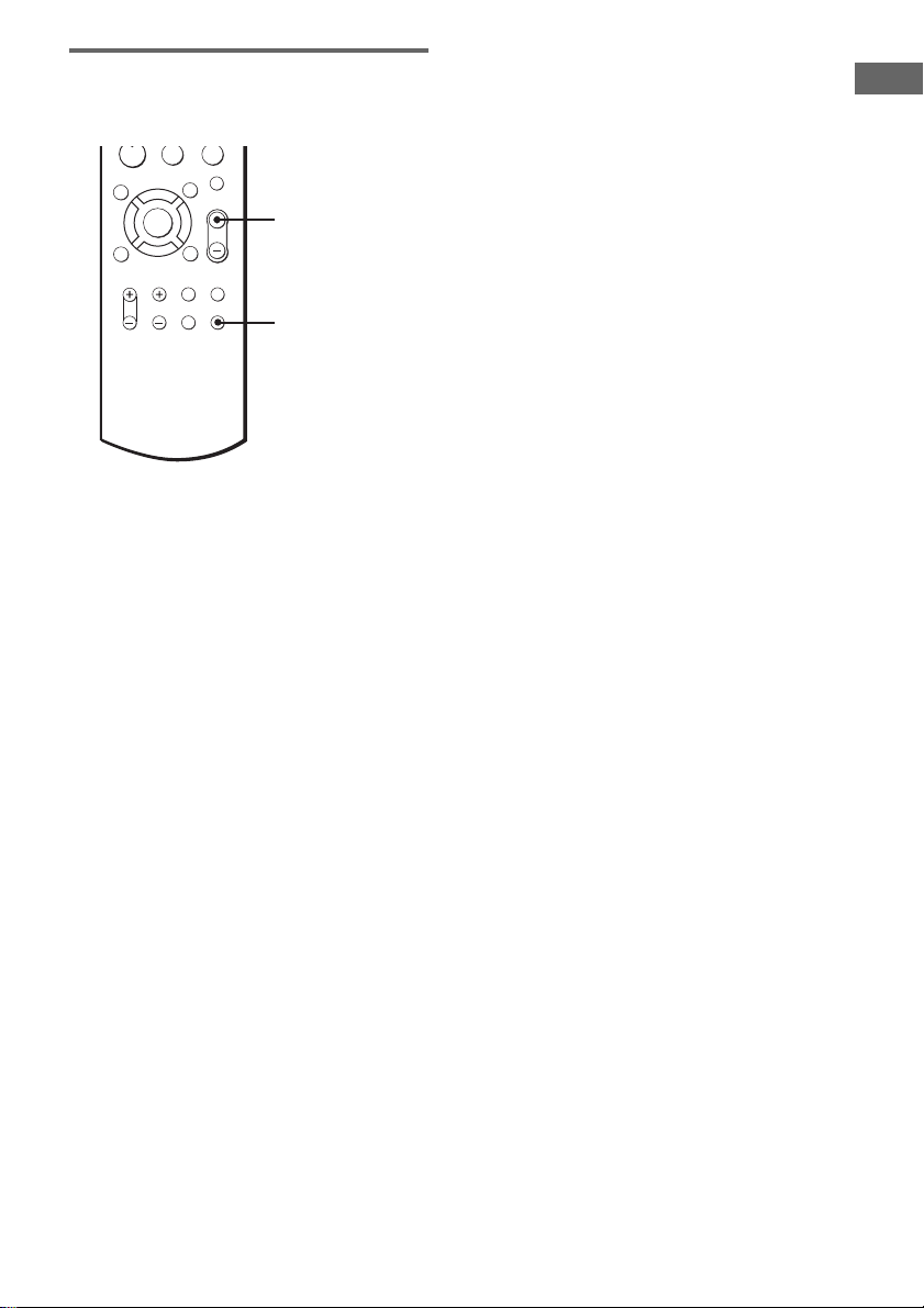
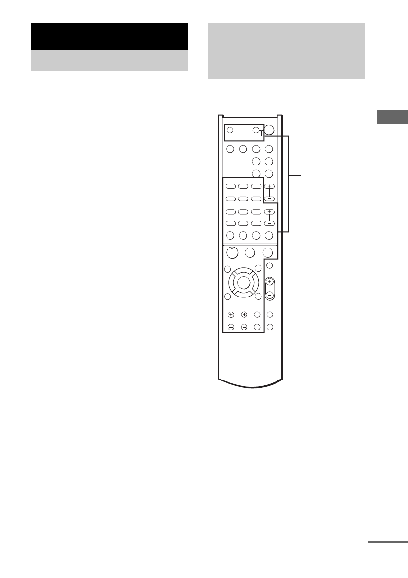
Using the supplied remote
to controlling the other
component
You can use the supplied remote to control other
Sony components.
SYSTEM STANDBY
SAT TV
AUX TUNER
;
PL/PLII A.F.D.
FM MODE
D.TUNING
SUBTITLE
MEMORY SHIFT
>
+
M
CLEAR
SEARCH MODE
X
A
V MEN
F
ENTER
f
RETURN/EXIT
VIDEO
?/1
SLEEP
SOUND
FIELD
PRESET/
CH/D.SKIP
-
x
MUTING
U
MASTER
VOL
O
TV/
MAIN
MENU
WIDE TEST TONE
Remote buttons
for operating
other
components
TV ?/1 AV ?/1
VIDEO DVD
AAC
BI-LING
123
AUDIO ANGLE
456
TIME SWAP JUMP
789
.
0/10 >10/11 ENTER/12
–
TUNING DISC ALT
m
ANT
N
TOP MENU/
GUIDE
Gg
DISPLAY
TV VOL TV CH
Other Operations/Settings
continued
23
GB
Page 24

Remote
Button
AV ?/1 TV/VCR/
SYSTEM
STANDBY
(Press
AV ?/1
while
holding
down ?/1)
1–9 and 0/10
(After
pressing
ALT)
SHIFT Tuner Press repeatedly to
D.TUNING Tuner Tuner station direct
TUNER +/– Tuner Scans radio stations.
MEMORY Tuner Stores the radio
FM MODE Tuner Selects FM monaural
>10/11
(After
pressing
ALT)
AUDIO TV/VCR/
TIME CD pl ay er /
PRESET/
CH/D.SKIP
+/–
Operations Function
CD player/
DVD player/
Control center/
TV/VCR/
Satellite tuner/
CD player/
DVD player/
Tuner Use with “SHIFT”
CD player Selects track numbers.
TV/VCR/
Satellite tuner
CD player Selects track numbers
TV Selects channel 11.
DVD player
DVD player
Tuner Scans and selects
TV/VCR/
Satellite tuner
CD player/
DVD player
Turns the audio and
video components on
or off.
Turns off the system
and other Sony audio/
video components.
button to select tuner
preset station numeric
input during
D.TUNING or
MEMORY mode.
0 selects track 10.
Selects channel
numbers.
select a memory page
for presetting radio
stations or tuning to
preset stations.
key-in-mode.
stations.
or stereo reception.
over 10.
Changes the sound to
Multiplex, Bilingual
or Multi channel TV
Sound.
Shows the time or
displays the playing
time of disc, etc.
preset stations.
Selects preset
channels.
Skips discs (multi-
disc changer only).
Remote
Button
ENTER/12
(After
pressing
ALT)
DISC CD player Selects a disc directly
DISPLAY TV/VCR/
ANT VCR Selects output signal
./> VCR/
m/M CD player/
H VCR/
X VCR/
x VCR/
AV MENU VCR/Satellite
V/v/B/b VCR/Satellite
RETURN
O/EXIT
SUBTITLE DVD player Changes the subtitles.
ANGLE DVD player To select viewing
Operations Function
TV/VCR/
Satellite tuner
TV Selects channel 12.
DVD player
CD player/
DVD player
DVD player
VCR Fast forwards or
CD player/
DVD player
CD player/
DVD player
CD player/
DVD player
tuner/DVD
player
tuner/DVD
player
DVD player Returns to the
Satellite tuner Exits the menu.
After selecting a
channel, disc or track
using the numeric
buttons, press to enter
the value.
(multi-disc changer
only).
Selects information
displayed on the TV
screen.
from aerial terminal:
TV signal or VCR
program.
Skips tracks.
Searches tracks
(forward or
backward).
rewinds.
Starts play.
Pauses play or record.
(Also starts recording
with components in
record standby.)
Stops play.
Displays menu.
Selects a menu item.
Press to enter the
selection.
previous menu.
angle or changes the
angles.
24
GB
Page 25

Remote
Button
CLEAR DVD player Press if you made a
SEARCH
MODE
TOP
MENU/
GUIDE
TV ?/1 TV Turns the TV on or
-/-- TV Selects the channel
TV VOL +/– TV Adjusts t he volum e of
TV CH +/– TV Select preset TV
TV/VIDEO TV Selects input signal:
SWAP* TV Swaps the small and
JUMP TV Toggles between the
ALT Remote Change remote key
* Only for Sony TVs with the picture-in-picture
function.
Notes
• The above explanation is intended to serve as an
example only. Therefore, de pending on the
component the above operation may no t be poss ibl e
or may operate differently than described.
• To activate the buttons with orange printi ng, press
ALT first before pressing the buttons .
• Before you use the V/v/B/b button for this
system’s operation, press MAIN MENU. To operate
other components, press AV MENU or TOP MENU/
GUIDE after pressing the function button.
Operations Function
mistake when you
press the number
button or press to
return to the
continuous play etc.
DVD player Select searching
mode. Press to select
the unit for search
(track, index, etc.).
DVD player Displays DVD title.
Satellite tuner Displays guide menu.
off.
entry mode, either one
or two digit.
the TV.
channels.
TV input or video
input.
large picture.
previous and the
current channels.
function to activate
those buttons with
orange printing.
Changing the factory
setting of a function
button on the remote
If the factory settings of the function buttons on
the remote do not match your system
components, you can change them. For
example, if you have a CD player and you do not
have a DVD player, you can assign the DVD
button to your CD player.
1 Hold down one of the function buttons
on the remote (VIDEO/DVD/SAT/TV/
AUX/TUNER) whose function you want
to change.
Example: Hold down DVD.
2 Press the corresponding button of the
component you want to assign to the
Function button.
Example: Press 1 (for CD player).
The following buttons are assigned to select
the functions:
To operate Press
CD player 1
VCR (command mode VTR 2*) 2
VCR (command mode VTR 3*) 3
DVD player 4
TV 5
DSS (Digital Satellite Receiver) 9
Tuner 0/10
* Sony VCRs are operated with a VTR 2 or 3
setting. These correspond to, 8mm and VHS
respectively.
To reset all the function buttons
to their factory setting
Press ?/1, AV ?/1 and MASTER VOL – at the
same time.
Other Operations/Settings
25
GB
Page 26
Setting up the speakers
Use the SET UP menu to set the types of the
speakers.
1 Press MAIN MENU repeatedly to select
SET UP menu.
2 Move the V/v/B/b button up or down
to select the parameter.
3 Move the V/v/B/b button to left or
right to select the setting.
4 Repeat steps 2 and 3 to adjust the other
parameters.
Speaker setup parameters
The initial setting is underlined.
L
x Front speaker distance ( DIS.)
Initial setting: 3.0 m
Lets you set the distance from your listening
position to the front speakers (A on page 10).
You can adjust from 1.0 meter to 7.0 meters in
0.1 meter steps.
If both front speakers are not placed an equal
distance from your listening position, set the
distance to the closest speaker.
x Center speaker distance ( DIS.)
Initial setting: 3.0 m
Lets you set the distance from your listening
position to the center speaker. You can enjoy a
higher quality sound effect if you place the
center speaker from a distance equal to the front
speaker distance (A on page 10) to a distance
1.5 meters closer to your listening position (B
on page 10).
x Surround speaker distance
SL
SR
( DIS.)
Initial setting: 3.0 m
Lets you set the distance from your listening
position to the surround speakers. You can enjoy
a higher quality sound effect if you place the
surround speakers from a distance equal to the
front speaker distance (A on page 10) to a
distance 4.5 meters closer to your listening
position (C on page 10).
R
C
If both surround speakers are not placed an equal
distance from your listening position, set the
distance to the closest speaker.
SL
x Surround speaker position ( PL.)
SR
Lets you specify the location of your surround
speakers for proper implementation of the
surround effects in the Cinema Studio EX
modes (page 21).
A
90˚
45˚
20˚
A
BB
•SIDE
Select if the location of your surround
speakers corresponds to section A.
• BEHIND (BEHD)
Select if the location of your surround
speakers corresponds to section B.
SL
x Surround speaker height ( HGT.)
SR
Lets you specify the height of your surround
speakers for proper implementation of the
surround effects of the Cinema Studio EX
modes (page 21).
B
A
B
60˚
A
30˚
•LOW
Select if the height of your surround speakers
corresponds to section A.
•HIGH
Select if the height of your surround speakers
corresponds to section B.
26
GB
Page 27

Customizing sound fields
• To enjoy the better sound quality, do not turn the
volume of the subwoofer too hi gh.
By adjusting the surround and level parameters,
you can customize the sound fields to suit your
particular listening situation.
Position your speakers and do the procedures
described in “6: Placing speakers” (page 10) and
“Checking if the sound comes from all
speakers” (page 15) before you customize a
sound field.
Adjusting the speaker level
and balance
You can adjust the balance and level of each
speaker. Sit in the listening position, then adjust
the test tone to sound the same level. These
settings are applied to all sound fields.
1 Press MASTER VOL +.
(Optimal volume level: Between 20–30.)
2 Press TEST TONE.
You will hear the test tone from each
speaker in sequence.
Front (left) t Center t Front (right) t
Surround (right) t Surround (left) t
Subwoofer
3 Press MAIN MENU repeatedly to select
LEVEL menu.
4 Move the V/v/B/b button up or down
to select the parameter.
5 Move the V/v/B/b button to left or
right to select the setting.
Tips
• To make more precise adjustment, start playing a
source encoded with multi channel surround effects
(DVD, etc.), then adjust the level and balance while
listening to the source.
• The system employs a test tone with a frequency
centered at 800 Hz.
• You can adjust the level of all speakers at the same
time. Turn VOL/PRESET TUNING on the control
center or press MASTER VOL +/– on the remote.
Notes
• The front balance, surround balance, center level,
surround level, and subwoofer level are shown in the
display during adjustment.
LEVEL menu parameters
L
x Front speaker balance ( BAL.)
Initial setting: midpoint (BALANCE)
Lets you adjust the balance between front left
and right speakers. You can adjust from L (+1 –
+8) to R (+1 – +8) in 1 increment steps.
x Surround speaker balance
SL
SR
( BAL.)
Initial setting: midpoint (BALANCE)
Lets you adjust the balance between surround
left and right speakers. You can adjust from L
(+1 – +8) to R (+1 – +8) in 1 increment steps.
x Center speaker level (CTR)
Initial setting: 0 dB
You can adjust from –10 dB to +10 dB in 1 dB
steps.
x Surround speaker level (SURR)
Initial setting: 0 dB
You can adjust from –10 dB to +10 dB in 1 dB
steps.
x Subwoofer level (S.W.)
Initial setting: 0 dB
You can adjust from –10 dB to +10 dB in 1 dB
steps.
x Dolby DRC
Initial setting: STD
When you listen to DVDs at low volume levels,
you can compress the dynamic range and finely
adjust for low-level sound. For details, see
“Making the low-level sound clear (DOLBY
DRC)” on page 22.
R
Adjusting the surround
parameter (EFFECT)
This parameter lets you adjust the “presence” of
the current surround effect. This effect is
available for the sound fields except for “A.F.D.
AUTO”, “A.F.D. Pro Logic”, “A.F.D. PL II
MOVIE”, “A.F.D. PL II MUSIC”.
Initial setting: EFFECT 10
Other Operations/Settings
continued
27
GB
Page 28

1 Start playing a source encoded with
multi channel surround effects (DVD,
etc.).
2 Press MAIN MENU repeatedly to select
“EFFECT”.
3 Move the V/v/B/b button to left or
right to select the setting.
You can adjust from 2 to 15 in 1 steps.
The surround effect increases as the number
increases.
28
GB
Page 29

Additional Information
Precautions
On cleaning
Clean the cabinet, panel and controls with a soft cloth
slightly moistened with a mild detergent solution. Do
not use any type of abrasive pad, scouring powder or
solvent such as alcohol or benz ine.
On safety
Should any solid object or liquid fall into the cabinet,
unplug the control center and have it checked by
qualified personnel before operating it any further.
On power sources
• Before operating the unit, check that the operating
voltage is identical with your local power supply.
The operating voltage is indicated on the nameplate
at the rear of the subwoofer.
• The unit is not disconnected from the AC power
source (mains) as long as it is connected to the wall
outlet, even if the control center itself has been turned
off.
• If you are not going to use the system for a long time,
be sure to disconnect the subwoofer from the wall
outlet. To disconnect the AC power cord, grasp the
plug itself; never pull the cord.
• AC power cord must be changed only at the qualified
service shop.
On heat buildup
Although the unit heats up durin g operation, this is not
a malfunction. If you continuou sly use this unit at a
large volume, the cabinet temperature of the top, side
and bottom rises considerably. To avoid burning
yourself, do not touch the cabinet.
On placement
• Place the subwoofer in a location with adequate
ventilation to prevent heat buildup and prolong the
life of the subwoofer.
• Do not place the control center and sub woofer near
heat sources, or in a place subj ect to direct sunlight,
excessive dust or mechanical shock.
• Do not place anything on top of the cabinet that
might block the ventilation holes an d cause
malfunctions.
• Use caution when placing the s ubwoofer or a sp eaker
stand (not supplied) that is attached with the front/
rear speakers on a specially tre ated (waxed, oiled,
polished, etc.) floor, a s staining or discolor ation may
result.
On operation
Before connecting other components, be sure to turn
off and unplug the AC power cord of the subwoofer.
If you have any question or problem concerning your
system, please consult your nearest Sony dealer.
Additional Information
29
GB
Page 30
Troubleshooting
If you experience any of the following
difficulties while using the control center, use
this troubleshooting guide to help you remedy
the problem. Should any problem persist,
consult your nearest Sony dealer.
When bringing the system in for repairs, be sure
to bring in the entire system (control center and
subwoofer). This product is system product, and
the entire system is needed to determine the
location requiring repair.
The multi channel surround effect of the Dolby
Digital or DTS is not obtained.
• Check that the DVD software, etc. is recorded in
Dolby Digital or DTS.
• If you connect the DVD player, etc. to the digital
input jack on this system, check the audio setting
(for digital audio output) of the component
(page 7).
• Check that the audio track is correctly selected on
the DVD player. (Check the audio setting of the
DVD menu.)
There is no sound or only a very low-level
sound is heard.
• Check that the speakers and components are
connected securely.
• Check that you have selected the correc t
component on the control center.
• Press MUTING if muting function is activated.
The left and right sounds are unbalanced or
reversed.
• Check that the speakers and components are
connected correctly and securely.
• Adjust balance parameters in the LEVEL menu.
There is severe hum or noise.
• Check that the speakers and components are
connected securely.
• Check that the connecting cords are a way from a
transformer or motor, and a t least 3 meters away
from a TV set or fluorescent light.
• Move your TV away from the audio components.
• The plugs and jacks are dirty. Wipe them with a
cloth slightly moistened with alcohol.
There is no sound from the center speaker.
• If you connect the DVD player, etc. to the digital
input jack on this system, check the audio setting
(for digital audio output) of the component
(page 7).
• Make sure the sound field function is on (press
SOUND FIELD +/–).
• Select the CINEMA STUDIO EX mode
(page 21).
• Adjust the speaker level (page 27).
There is no sound or only a very low-level
sound is heard from the surround speakers.
• If you connect the DVD player, etc. to the digital
input jack on this system, check the audio setting
(for digital audio output) of the component
(page 7).
• Make sure the sound field function is on (press
SOUND FIELD +/–).
• Select the CINEMA STUDIO EX mode
(page 21).
• Adjust the speaker level (page 27).
The surround effect cannot be obtained.
• Make sure the sound field function is on (press
SOUND FIELD +/–).
The FM reception is poor.
• Use a 75-ohm coaxial cable (not supplied) to
connect the receiver to an outdoor FM antenna as
shown below. If you connect the receiver to an
outdoor antenna, ground it against lightning. To
prevent a gas explosion, do not connect the ground
wire to a gas pipe.
Outdoor FM antenna
ANTENNA
75
FM
COAXIAL
AM
U
Ground wire
(not supplied)
To ground
Radio stations cannot be tuned in.
• Check that the antennas are connected securely.
Adjust the antennas and conne ct an external
antenna if necessary.
• The signal strength of the stations is too weak
(when tuning in with automatic tuning). Use
manual tuning.
• No stations have been preset or the preset stations
have been cleared (when tuning by scanning
preset stations). Preset the stations (page 19).
30
GB
Page 31

The remote does not function.
• Point the remote at the remote sensor on the
control center.
• Remove any obstacles in the path between the
remote and the control center.
• Replace both batteries in the remote with new
ones, if they are weak.
• Make sure you select the correct function on the
remote.
When the following message
appears in the display
“UNLOCK”
• You select DVD, AUX or SAT as the function and
no component is connected to the digital input jacks.
• The component is correctly connected, but the
component is turned off or the playback has not
started.
“PROTECT”
• The speaker cords are short-circuited (page 12).
cTurn off the power, then reconnect the speaker
cords correctly.
• The system heats up because th e system was us ed for
a long time with loud volume.
cTurn off the power and leave the system for a
while.
cTurn down the volume.
Reference sections for clearing the
system’s memory
To clear See
All memorized settings page14
Specifications
Amplifier/subwoofer section
POWER OUTPUT
Rated Power Output at Stereo Mode
(6 ohms 1 kHz, THD 10%)
50 W + 50 W
(6 ohms 1 kHz, THD 0.7%)
40 W + 40 W
Reference Power Output
(THD 10%) Front*: 50 W/ch
Center*: 50 W
Surround*: 50 W/ch
(6 ohms)
Subwoofer*: 90 W
(3 ohms)
(THD 0.7%) Front*: 40 W/ch
Center*: 40 W
Surround*: 40 W/ch
(6 ohms)
Subwoofer*: 70 W
(3 ohms)
* Depending on the sound field settings and the so urce,
there may be no sound output.
Frequency response 20 Hz – 20 kHz
Inputs (Digital)
AUX (Coaxial) Impedance: 75 ohms
S/N: 90 dB
(A, 20 kHz LPF)
DVD, SAT (Optical) S/N: 90 dB
(A, 20 kHz LPF)
Inputs (Analog)
TV, VIDEO Sensitivity: 700 mV
Impedance: 50 kilohms
S/N: 84 dB
(A, 20 kHz LPF)
Enclosure type Advanced S.A.W.
magnetically shielded
Speaker unit 16 cm cone type
Rated frequency range 30 Hz – 200 Hz
High frequency cut-off frequency
150 Hz
Additional Information
FM tuner section
Tuning range 87.50 MHz – 108.0 MHz
Antenna terminals 75 ohms, unbalanced
S/N
Mono: 76 dB
Stereo: 70 dB
Sensitivity
Mono: 18.3 dBf, 2.2 µV/75 ohms
Stereo: 38.3 dBf, 22.5 µV/75 ohms
Useable sensitivity 11.2 dBf, 1 µV/75 ohms
continued
31
GB
Page 32

Harmonic distortion at 1 kHz
Mono: 0.3%
Stereo: 0.5%
Separation 45 dB at 1 kHz
Frequency response 30 Hz – 15 kHz,
+0.5/–2 dB
Selectivity 60 dB at 400 kHz
AM tuner section
Tuning range 531 kHz – 1,602 kHz
(With 9-kHz tuning scale)
Antenna Loop antenna
Usable sensitivity 50 dB/m (at 999 kHz)
S/N 54 dB (at 50 mV/m)
Harmonic distortion 1.0% (50 mV/m, 400 Hz)
Power requirements
Power requirements 220–230 V AC, 50/60 Hz
Power consumption 68 W
Power consumption (during standby mode)
0.8 W
Dimensions (w/h/d)
Control center: 58 × 215 × 308 mm
Control center (with the stand):
130 × 233 × 308 mm
Subwoofer: 224 × 318.5 × 344 mm
Mass (Approx.)
Control center: 1.3 kg
Control center (with the stand):
1.4 kg
Subwoofer: 7.1 kg
Glossary
Surround sound
Sound that consists of three elements: direct sound,
early reflected sound (early refl ec t io ns) and
reverberative sound (reverberation). The acoustics of
the surrounding space affect the way these three sound
elements are heard. Surround sound combines these
sound elements in such a way that you actually can
sense the size of the venue, as well as its type.
• Types of sound
Early reflections
Direct sound
• Transition of sound from rear speakers
Direct sound
Level
Early
reflections
Reverberation
Reverberation
32
Satellite speaker section
Front, center and surround sp eakers
SS-MSP250
Speaker system Full range, magnetically
shielded
Speaker units 5.7 cm cone type
Rated impedance 6 ohms
Sensitivity level 85 dB (1 W, 1m)
Frequency range 130 Hz – 20,000 Hz
Dimensions (w/h/d) Approx. 77 × 115 × 89 mm
including front grille
Mass Approx. 0.5 kg
Design and specifications are subject to change
without notice.
GB
Early reflection time
Time
Digital Cinema Sound
This is the generic name of the surround sound
produced by digital signal processing technology
developed by Sony. Unlike previous surround sound
fields mainly directed at the reproduction of music,
Digital Cinema Sound is designed specifi cal l y for the
enjoyment of movies.
Dolby Digital
This sound format for movie theaters is more advanced
than Dolby Surround Pro Logic. In this format, the rear
speakers output stereo sound with an expanded
frequency range and a sub woofer channel for deep
bass is independently provided. This format is also
called “5.1” because the sub woofer channel is counted
as 0.1 channel (since it functions only when a deep bass
Page 33

effect is needed). All six channels in this format are
recorded separately to realize su perior channel
separation. Furthermore, sin ce al l th e si gnals are
processed digitally, less signal degradation occurs.
Dolby Pro Logic (II)
A surround technology that employs matrix
decoding to create multi-channel sound from
sources recorded in 2 channels.
• Dolby Pro Logic
Decodes 2 channel sources for playback in 4
channels. The front (left and right) and center
channels have a 20-20 kHz bandwidth. The monaural
surround channel has a 100-7 kHz bandwidth.
Requires Dolby Surround encoded source material to
achieve proper surround effects .
• Dolby Pro Logic II Movie
Expands all 2 channel (stereo) sources for playback
in 5 channels. It features a dire ctional surround
environment appropriate for the playback of film
sound tracks, improved stereo imaging in the
surround channels, and a 20-20 kHz bandwidth
across all channels.
• Dolby Pro Logic II Music
An expanded 5 channel sound environment
specifically designed for the playback of music. It
features a less directional surround channels for more
realistic surround sound, improved stereo imaging in
the surround channels, and a 20-20 kHz bandwidth
across all channels.
Additional Information
33
GB
Page 34

List of button locations and reference pages
Illustrati
How to use this page
Use this page to find the location of buttons and other
parts of the system that are mentioned in the text.
Control center
ALPHABETICAL ORDER
Display 1 (17)
DISPLAY POSITION 3 (18)
INPUT SELECTOR 8 (16, 18,
19)
MUTING 5 (16, 30)
Remote sensor 2
SOUND FIELD f/F 9
VOL/PRESET TUNING 4 (19)
VOL/PRESET TUNING control
7 (16, 19, 27)
NUMBERS AND SYMBOLS
?/1 (power) 6
DISPLAY POSITION 3 (18)
R R
Name of button/ part Reference page
on number
r
1
2
3
9
8
4
7
5
34
6
GB
Page 35

Remote control
ALPHABETICAL ORDER
A – N P – T V – W
A.F.D. wg
AAC BI-LING rf
ALT e; (18, 19, 20, 23)
ANGLE rs
ANT qk
AUDIO rd
AUX wa (16, 25, 31)
AV ?/1 (power) 2 (25)
AV MENU es
CLEAR 8
D.TUNING wh (18)
DISC ea
DISPLAY eh (31)
DVD wd (16, 25, 31)
ENTER/12 7
FM MODE rg (19)
JUMP wl
MAIN MENU ef (22, 26, 27, 28)
MASTER VOL +/– qa (15, 16,
25, 27)
MEMORY ql (19)
MUTING q; (16, 30)
Numeric buttons w; (18, 19, 20,
25)
;PL/PLII rh
PRESET/CH/D.SKIP +/– 6 (20)
RETURN O/EXIT ed
SAT 4 (16, 25, 31)
SEARCH MODE ea
SHIFT 7 (19, 20)
SLEEP 1 (23)
SOUND FIELD +/– wj (21, 30)
SUBTITLE wk
SWAP r;
TEST TONE eg (15, 27)
TIME ra
TOP MENU/GUIDE ek
TUNER 5 (16, 18, 19, 20, 25)
TUNING + 8 (18, 19)
TUNING – qk (18, 19)
TV 3 (16, 25)
TV CH +/– qf
TV VOL +/– qg
TV/VIDEO qs
TV ?/1 (power) wf
SYSTEM STANDBY
;
FM MODE
D.TUNING
SUBTITLE
MEMORY SHIFT
>
+
M
CLEAR
SEARCH MODE
X
A
F
ENTER
f
RETURN/EXIT
?/1
SLEEP
SAT TV
AUX TUNER
PL/PLII A.F.D.
SOUND
FIELD
PRESET/
CH/D.SKIP
-
x
MUTING
V MEN
U
MASTER
O
TV/
MAIN
VIDEO
MENU
WIDE TEST TONE
rh
rg
rf
rd
rs
ra
r;
el
ek
ej
eh
TV ?/1 AV ?/1
VIDEO DVD
AAC
BI-LING
123
AUDIO ANGLE
456
TIME SWAP JUMP
789
.
0/10 >10/11 ENTER/12
–
TUNING DISC ALT
m
ANT
N
TOP MENU/
GUIDE
Gg
DISPLAY
TV VOL TV CH
VIDEO ws (16, 25)
WIDE qd
NUMBERS AND SYMBOLS
?/1 (power) 1
V/v/B/b ej (22, 26, 27, 28)
M 8 (24)
m qk (24)
> ql
. el
N qj
X qh
x 9
-/-- ea
0/10 el (25)
>10/11 ql
wf
wd
ws
wa
wg
wh
wj
w;
wk
wl
ql
e;
qk
ea
qj
qh
es
VOL
ed
ef
qg
eg
qf
TV ?/1 AV ?/1
VIDEO DVD
AAC
BI-LING
AUDIO ANGLE
TIME SWAP JUMP
.
0/10 >10/11 ENTER/12
–
TUNING DISC ALT
m
ANT
N
TOP MENU/
GUIDE
Gg
DISPLAY
TV VOL TV CH
?/1
SLEEP
SYSTEM STANDBY
SAT TV
AUX TUNER
;
PL/PLII A.F.D.
SOUND
FIELD
FM MODE
D.TUNING
123
SUBTITLE
456
PRESET/
CH/D.SKIP
789
MEMORY SHIFT
>
+
-
M
CLEAR
SEARCH MODE
X
x
MUTING
A
V MEN
U
F
MASTER
VOL
ENTER
f
O
RETURN/EXIT
TV/
MAIN
VIDEO
MENU
WIDE TEST TONE
Additional Information
1
2
3
4
5
6
7
8
9
0
qa
qs
qd
35
GB
Page 36

Index
A
Adjusting
LEVEL parameters
SET UP parameters
speaker volume
D
Digital Cinema Sound 21
DOLBY DRC
E
EFFECT parameter 27
L
LEVEL menu 27
S
Selecting
component
sound field
SET UP menu
Sleep timer
Sound field
customizing
pre-programmed
resetting
selecting
Speakers
adjusting speaker volume
connection
placement
Supplied accessories
15, 27
22
16
21
26
23
27
21
14
21
11
10
4
27
26
15, 27
36
T
Test tone 15
GB
Page 37

Page 38

AVERTISSEMENT
Afin d’éviter tout risque d’incendie ou
d’électrocution, ne pas exposer cet
appareil à la pluie ou à l’humidité.
Afin d’éviter tout risque d’incendie, ne pas couvrir les
ailettes de ventilation de cet appareil avec des papiers
journaux, des nappes, des rideaux, etc. Ne pas poser de
bougies allumées sur l’appareil.
Pour éviter tout risque d’incendie ou d’électrocution,
ne pas poser d’objets contenant du liquide, comme des
vases, sur l’appareil.
Ne pas jeter les piles dans les
ordures ménagères. Déposez-les
correctement aux endroits
préconisés.
N’installez pas l’appareil dans un espace confiné
comme dans une bibliothèque ou un meuble encast ré .
Cet appareil intègre les système s Dolby* Digital et Pr o
Logic Surround et le système surround numérique
DTS** Digital Surround.
* Fabriqué sous licence de Dolby Laboratories.
Le terme « Dolby », « Pro Logic » et le sigle double
D sont des marques commerciales de Dolby
Laboratories.
**« DTS » et « DTS Digital Surround » sont des
marques de fabrique de Digital Theater Systems,
Inc.
Au sujet de ce mode d’emploi
Les instructions de ce mode d’emploi décrivent
les touches de la télécommande.
Vous pouvez aussi utiliser les touches du centre
de commande si elles ont le même nom ou un
nom similaire que celles de la télécommande.
Pour l’emplacement des touches de la
télécommande, voir « Utilisation de la
télécommande pour le contrôle d’autres
appareils » à la page 24.
SYSTEM STANDBY
;
FM MODE
D.TUNING
SUBTITLE
MEMORY SHIFT
>
+
M
CLEAR
SEARCH MODE
X
A
F
ENTER
f
RETURN/EXIT
?/1
SLEEP
SAT TV
AUX TUNER
PL/PLII A.F.D.
SOUND
FIELD
PRESET/
CH/D.SKIP
-
x
MUTING
V MEN
U
MASTER
VOL
g
O
TV/
MAIN
VIDEO
MENU
WIDE TEST TONE
TV ?/1 AV ?/1
VIDEO DVD
AAC
BI-LING
123
AUDIO ANGLE
456
TIME SWAP JUMP
789
.
0/10 >10/11 ENTER/12
–
TUNING DISC ALT
m
ANT
N
TOP MENU/
GUIDE
G
DISPLAY
TV VOL TV CH
FR
2
Page 39

Table des matières
Préparatifs
1: Déballage ............................................4
2: Raccordement du centre de commande
et du caisson de graves .....................5
3: Raccordement d’appareils munis de
prises de sortie audionumérique.......6
4: Raccordement d’appareils vidéo.........8
5: Raccordement des antennes................9
6: Emplacement des enceintes . .............10
7: Raccordement des enceintes.............11
8: Fixation du support...........................13
9: Raccordement du cordon
d’alimentation.................................14
Vérification des connexions et des
réglages...........................................14
Ecoute du son des appareils
raccordés
Sélection d’un appareil .........................16
A propos des indications affichées .......17
Réception de stations FM/AM..............18
Préréglage de stations radio ..................19
Ecoute du son surround
Sélection d’un champ sonore................21
Informations
complémentaires
Précautions............................................ 31
Guide de dépannage.............................. 32
Spécifications........................................ 33
Glossaire............................................... 34
Liste des touches et pages de
référence......................................... 36
Index..................................................... 38
FR
Autres fonctions/réglages
Utilisation de la minuterie sommeil......24
Utilisation de la télécommande pour le
contrôle d’autres appareils..............24
Changement des réglages usine des
touches d’entrée de la
télécommande.................................27
Réglage des enceintes ... ........................27
Personnalisation des champs sonores ...29
FR
3
Page 40

Préparatifs
1: Déballage
Vérifiez si vous êtes bien en possession de tous
les articles suivants:
• Centre de commande (1)
• Caisson de graves (1)
• Micro-enceintes satellites (5)
• Support de centre de commande et vis (1 de
chaque)
• Télécommande (1)
• Piles R6 (modèle AA) (2)
• Cordons d’enceintes (longs) (2)
• Cordons d’enceintes (courts) (3)
• Cordon système (1)
• Cordon numérique optique (1)
• Antenne fil FM (1)
• Antenne cadre AM (1)
• Tampons de pieds d’enceintes (20)
• Autocollant d’enceinte (1)
• Adaptateurs d’enceintes pour suspension au
mur et vis (5 de chaque)
• Ce mode d’emploi (1)
• Guide d’installation des enceintes (1)
• N’utilisez pas une pile neuve avec une pile usée.
• N’exposez pas le capteur de rayons infrarouges du
centre de commande à la lumière directe du soleil ou
d’une lampe. Ceci peut entraîner une panne.
• Si vous prévoyez de ne pas utiliser la télécommande
pendant un certain temps, enlevez les piles pour
éviter tout dommage dû à la fuite des piles et à la
corrosion.
• Eteignez tous les éléments avant de les raccorder.
• Les fiches doivent être insérées à fond dans les prise s
pour éviter tout bourdonneme nt et parasite.
Mise en place des piles dans
la télécommande
Insérez deux piles R6 (modèle AA) en orientant
correctement les pôles + et – dans le logement
des piles.
Conseil
Normalement, les piles devraient durer environ 6 mois.
Lorsque la télécommande n’agit plus sur le centre de
commande, remplacez les deux piles par des neuves.
Remarques
• Ne laissez pas la télécommande à un endroit
extrêmement chaud ou humide.
FR
4
Page 41

2: Raccordement du centre de commande et du caisson de
graves
Cordons requis
Cordon système (fournis)
Centre de commande
Préparatifs
INPUT
DVD
SAT AUX
Caisson de graves
DIGITAL
COAXIALOPTICAL
CONTROL
L
R
VIDEO
ANALOG
TV
FM
COAXIAL
75
FRONT R
SURR R
ANTENNA
U
SPEAKERS
CENTER
CONTROL
AM
FRONT L
SURR L
Remarque
Pensez à toujours débrancher le cordon d’alimentation secteur avant de brancher ou de
débrancher le cordon système.
Si vous débranchez le cordon système lorsque le cordon d’alimentation secteur est raccordé, le système risque de ne
pas s’allumer. Dans ce cas, débranchez le cordon d’alimentation secteur, rebranchez le cordon système, puis
raccordez le cordon d’alimentation secteur et rallumez le système.
FR
5
Page 42

.
3: Raccordement d’appareils munis de prises de sortie
audionumérique
Raccordez les prises de sortie audionumérique de votre lecteur DVD ou d’un autre appareil (« Play
Station 2 », lecteur CD, Platine MD, tuner satellite, etc.) aux prises d’entrée audionumérique du centre
de commande pour bénéficier d’un son surround multicanaux comme au cinéma.
Raccordez les prises de sortie vidéo du lecteur DVD ou de la « Play Station 2 » aux prises d’entrée
vidéo du téléviseur.
Remarque
Le signal vidéo ne peut pas être transmis à ce système. Lorsque vous raccordez des appareils vidéo (magnétoscope,
téléviseur, etc.) reliez la prise de sortie vidéo de l’appareil vidéo à la prise d’entrée vidéo du téléviseur.
Cordons requis
Cordon numérique optique (fourni)
Cordon numérique coaxial (non fourni)
Centre de commande
OUTPUT
OPTICAL
OUT
Lecteur DVD ou
« Play Station 2 »
DIGITAL
INPUT
DVD SAT AUX
OUTPUT
OPTICAL
OUT
COAXIALOPTICAL
Tuner satellite
L
R
VIDEO
ANALOG
ANTENNA
FM
AM
U
COAXIAL
75
TV
OUTPUT
COAXIAL
OUT
Autres appareils audio/vidéo
numériques (lecteur CD,
CONTROL
platine MD, etc.)
Conseil
Toutes les prises d’entrée numérique sont compatibles avec les fréquences d’échantillonnage de 32 kHz, 44,1 kHz
et 48 kHz.
FR
6
Page 43

Réglages à effectuer lorsqu’un lecteur DVD Sony ou une « Play Station
2 » sont utilisés
Lorsque vous raccordez un lecteur DVD ou une « Play Station 2 » comme indiqué à la page précédente,
effectuez les réglages suivants sur chaque appareil. Pour le détail, reportez-vous au mode d’emploi de
l’appareil.
Lecteur DVD
1 Sélectionnez « AUDIO SETUP » sur
l’écran de configuration.
2 Réglez « AUDIO DRC » sur « WIDE
RANGE ».
3 Réglez « DIGITAL OUT » sur « ON ».
4 Réglez « DOLBY DIGITAL » sur
« DOLBY DIGITAL ».
5 Réglez « DTS » sur « ON ».
« Play Station 2 » est une marque de fabrique de Sony Computer Entertainment.
« Play Station 2 »
1 Sélectionnez « AUDIO SETTING » sur
l’écran de configuration.
2 Sélectionnez « AUDIO DIGITAL
OUTPUT ».
3 Réglez « OPTICAL DIGITAL OUTPUT »
sur « ON ».
4 Réglez « DOLBY DIGITAL » sur « ON ».
5 Réglez « DTS » sur « ON ».
Préparatifs
FR
7
Page 44

4: Raccordement d’appareils vidéo
Cordons requis
Cordon audio (non fourni)
Lorsque vous raccordez un cordon, veillez à faire correspondre les couleurs des fiches du cordon et
celles des prises de l’appareil: fiche blanche (gauche) et prise blanche, et fiche rouge (droite) à prise
rouge.
Remarque
Le signal vidéo ne peut pas être transmis à ce système. Lorsque vous raccordez des appareils vidéo (magnétoscope,
téléviseur, etc.) reliez la prise de sortie vidéo de l’appareil vidéo à la prise d’entrée vidéo du téléviseur.
Blanc (G)
Rouge (D)
Magnétoscope
OUTPUT
AUDIO
OUT
L
R
Centre de commande
DIGITAL
INPUT
DVD SAT AUX
COAXIALOPTICAL
L
R
VIDEO
ANALOG
TV
AUDIO
OUT
OUTPUT
75
L
R
ANTENNA
FM
COAXIAL
CONTROL
AM
U
Téléviseur
FR
8
Page 45

5: Raccordement des antennes
Raccordez l’antenne cadre AM et l’antenne fil FM fournies.
Antenne fil FM
(fournie)
Préparatifs
Antenne cadre AM
(fournie)
DIGITAL
INPUT
DVD SAT AUX
COAXIALOPTICAL
L
R
VIDEO
ANALOG
ANTENNA
CONTROL
FM
AM
U
COAXIAL
75
TV
Remarques sur le raccordement des antennes
• Pour éviter les bruits parasites, posez l’antenne cadre AM à l’écart de l’ampli-tuner et des autres appareils.
• Veillez à bien dérouler l’antenne fil FM.
• Après avoir raccordé l’antenne fil FM, laissez-la si possible à l’horizontale.
• Lorsque vous raccordez l’antenne AM fournie à un appareil, raccordez le cordon noir (B) à la prise U, et le cordon
blanc (A) à l’autre prise.
FR
9
Page 46

6: Emplacement des enceintes
Pour obtenir un vrai son surround, les enceintes doivent être disposées de la façon suivante.
• Installez l’enceinte avant entre 1 et 7 mètres de la position d’écoute (A).
• Vous obtiendrez un meilleur effet sonore si vous placez l’enceinte centrale à une distance égale à
celle des enceintes avant (A) ou en la rapprochant de 1,5 mètre au maximum de votre position
d’écoute (B).
• Vous obtiendrez un meilleur effet sonore si vous placez l’enceinte surround à une distance égale à
celle des enceintes avant (A) ou en la rapprochant de 4,5 mètre au maximum de votre position
d’écoute (C).
• Placez le caisson de graves à la même distance de la position d’écoute que l’enceinte avant (gauche
ou droite).
Lorsque les enceintes surround sont sur les côtés
Caisson de graves
B
A A
45˚
CC
90˚
Position d’écoute
10
20˚
Lorsque les enceintes surround sont derrière vous
Caisson de graves
B
AA
45˚
CC
90˚
20˚
Remarque
Position d’écoute
Ne placez pas l’enceinte centrale et les enceintes surround plus loin de la position d’écoute que les enceintes avant.
FR
Page 47

7: Raccordement des enceintes
Installez toutes les enceintes avant de les raccorder.
Sur le caisson de graves
Raccordez les cordons d’enceintes en faisant correspondre les couleurs des fiches et des prises d’enceintes.
Sur les enceintes satellites
Collez les autocollants fournis (« FRONT L » etc., 5 couleurs) sur les enceintes satellites et branchez
les cordons d’enceintes en tenant compte de la couleur des autocollants et des tubes couleurs sur les
cordons d’enceintes.
Cordons d’enceintes (fournis)
Raccordez le cordon muni d’un tube noir sur la prise (–).
(–)
(+)
Tube noir
Tube rouge
Tube couleur
Fiche d’enceinte
Préparatifs
Enceinte avant
(D)
–
Black tube (–) Tube rouge (+)
Tube couleur
Caisson de graves
CONTROL
+
Rouge Vert Blanc
Gris
–
Enceinte surround
FRONT R
SURR R
(D)
Enceinte
centrale
–
SPEAKERS
+
Enceinte avant
+
FRONT LCENTER
SURR L
Bleu
–
Enceinte surround
+
(G)
(G)
–
+
voir page suivante
11
FR
Page 48

Pour éviter de court-circuiter
les enceintes
Les courts-circuits peuvent endommager les
enceintes et entraîner d’autres problèmes.
Assurez-vous que les extrémités dénudées
de chaque cordon d’enceinte ne touchent
pas les extrémités dénudées d’un autre
cordon.
Exemples de mauvaises connexions du
cordon d’enceinte
Fixation des enceintes
satellites au mur
Vissez les vis (non fournis) au mur. Les vis
doivent ressortir de 5 à 6 mm.
5 à 6 mm
Fixez l’attache murale d’enceinte (fournie) avec
la vis (fournie) et suspendez l’enceinte satellite à
la vis murale.
Stabilisation des enceintes
Pour éviter toute vibration ou déplacement des
enceintes pendant l’écoute, collez les tampons
fournis sous les enceintes. Si vous utilisez des
pieds d’enceintes (non fournis), vous n’avez pas
besoin de coller les tampons.
Utilisation des pieds d’enceintes
(non fournis)
Si vous utilisez les pieds vendus en option
(WS-FV10D, WS-WV10D), vous pourrez plus
facilement installer les enceintes comme vous
voulez.
WS-WV10D
(Fixation
murale)
4,2 mm
9,2 mm
Attache murale d’enceinte
Remarques
• Procurez les vis appropriées selon la matière et la
résistance du mur.
• Fixez les enceintes satellites sur un mur vertical et
plat, à un endroit où il est renforcé. Ne pas les fixer à
un mur qui n’est pas vertical, plat ou suffisamment
résistant.
• Renseignez auprès d’un vendeur ou d’un installateur
pour le type de vis à utiliser en fonction du type de
mur.
• Sony décline toute responsabilité quant aux
accidents ou dommages pouvant résulter d’une
mauvaise installation, d’une faible résistance du mur
ou d’un mauvais emploi des vis, d’un désastre
naturel, etc.
12
WS-FV10D
FR
Page 49

8: Fixation du support
Le centre de commande peut être installé en
position verticale ou horizontale. Lorsqu’il est
installé en position verticale, il faut rattacher le
support fourni. La disposition des éléments de
l’affichage peut être changée en fonction de la
position du centre de commande (page 18).
Utilisation du centre de
commande en position
verticale
Fixez le support en vissant la vis fournie
dans l’orifice au centre du centre de
commande.
m
Utilisation horizontale du
centre de commande
Posez le centre de commande sur une
surface plane.
Préparatifs
Remarques
• Il faut absolument rattacher le support lo rsque le
centre de commande est utilisé en position verticale.
• N’utilisez le support fourni que lorsque le centre de
commande est en position verticale. Il est inutile de
le fixer en position horizont ale.
• Pour déplacer le centre de commande, saisissez le
boîtier proprement dit. Si vous saisissez le support, il
risque de se briser.
• N’utilisez pas le centre de commande en position
verticale sans avoir fixé le support au préalable. Il ne
sera pas stable et risque de tomber.
• Rangez les vis hors de portée des enfants.
13
FR
Page 50

I
9: Raccordement du
Vérification des
cordon d’alimentation
Après avoir raccordé les divers appareils,
raccordé le cordon d’alimentation secteur du
caisson de graves à une prise secteur.
Cordon
d’alimentation
secteur
Caisson de graves
CONTROL
b
A une prise secteur
connexions et des
réglages
Configuration initiale du
système
La première fois que vous utilisez le système,
initialisez-le de la façon suivante.
Procédez de la même façon pour rétablir les
réglages par défaut.
?/1
1 Appuyez sur ?/1 pour éteindre le
système.
2 Appuyez sur ?/1 jusqu’à ce que
« INITIAL » apparaisse sur l’afficheur.
Le nom de l’entrée actuelle apparaît.
Les réglages par défaut des paramètres
suivants sont rétablis.
• Tous les réglages des menus SET UP,
LEVEL et EFFECT.
• Le champ sonore mémorisé pour chaque
entrée.
• Toutes les stations préréglées.
En outre, le volume revient à son niveau
minimal (MIN).
14
FR
Page 51

Contrôle de la sortie du son
sur toutes les enceintes
.
X
ENTER
F
f
AV MENU
O
RETURN/EXIT
TV/
VIDEO
WIDE TEST TONE
x
MUTING
MASTER
VOL
MAIN
MENU
N
TOP MENU/
GUIDE
Gg
DISPLAY
TV VOL TV CH
MASTER VOL
TEST TONE
1 Appuyez sur MASTER VOL +.
(Niveau sonore optimal : Entre 20 – 30.)
2 Appuyez sur TEST TONE.
Le signal d’essai sort successivement de
chaque enceinte.
Avant (gauche) t Centre t Avant
(droite) t Surround (droite) t Surround
(gauche) t Caisson de graves
Lorsque le signal d’essai est fourni, si aucun
son ne sort des enceintes, ou s’il sort d’une
enceinte dont le nom n’est pas indiqué sur
l’afficheur, c’est qu’il y a un court-circuit
ou que la connexion est mauvaise. Dans ce
cas, vérifiez de nouveau les raccordements
des enceintes.
3 Appuyez une nouvelle fois sur TEST
TONE pour arrêter le signal d’essai.
Préparatifs
15
FR
Page 52

Ecoute du son des appareils raccordés
Sélection d’un appareil
Vous pouvez sélectionner uniquement des
appareils Sony.
1 Appuyez sur une des touches de
fonction.
Lorsque vous utilisez le centre de
commande, appuyez à plusieurs reprises sur
INPUT SELECTOR.
Pour sélectionner Appuyez sur
Lecteur DVD ou « Play Station
2 »
Tuner satellite SAT
Autre appareil audio/vidéo
numérique (lecteur CD, platine
MD, etc.)
Magnétoscope VIDEO
Téléviseur TV
Tuner TUNER
DVD
AUX
2 Allumez l’appareil et démarrez la
lecture.
Si vous sélectionnez un appareil qui est
aussi relié au téléviseur (magnétoscope ou
lecteur DVD), allumez le téléviseur et
réglez l’entrée vidéo du téléviseur
correspondante à l’appareil sélectionné.
3 Appuyez sur MASTER VOL +/– pour
régler le volume.
Lorsque vous utilisez le centre de
commande, tournez VOL/PRESET
TUNING.
Pour couper le son
Appuyez sur MUTING.
Lecture d’un DVD sur le
lecteur DVD raccordé (non
fourni)
Si vous raccordez un lecteur DVD ou une « Play
Station 2 » à un téléviseur, vous pourrez voir des
DVD.
1 Appuyez sur DVD.
2 Sélectionnez l’entrée vidéo sur le
téléviseur.
Pour le détail, reportez-vous au mode
d’emploi du téléviseur.
3 Posez un DVD sur le lecteur DVD ou la
« Play Station 2 ».
4 Démarrez la lecture du DVD.
16
FR
Page 53

A propos des indications affichées
5
21
La disposition des éléments de l’affichage peut être changée en fonction de la position du centre de
commande (page 18).
Affichage vertical Affichage horizontal
Ecoute du son des appareils raccordés
2
1
FM
STEREO
AM
MONO
L C R
SW
L.F.E.
SL S SR
DIGITAL
PLII
0
A AM: S’allume lorsqu’une station AM est
accordée.
B FM: S’allume lorsqu’une station FM est
accordée.
C MONO: S’allume lorsqu’une station FM est
accordée en mode mono.
D STEREO: S’allume lorsqu’une station FM
est accordée en mode stéréo.
E : S’allume lorsque le disque reproduit
L.F.E.
contient le canal LFE (Effet basse fréquence)
et que le signal du canal LFE est reproduit.
F MEMORY: S’allume pendant le préréglage
d’une station radio.
G DTS: S’allume pendant le décodage de
signaux DTS par le système.
H ; DIGITAL: S’allume pendant le décodage
de signaux Dolby Digital par le système.
I ; PL (II): S’allume pendant le traitement de
signaux en Pro Logic ou Pro Logic (II).
89
6
MHz
KHz
MEMORY
DTS
7
1
2
5
43
6
0
43
STEREO
MONO
L C R
SW
SL S SR
DTS
7
MHz
KHz
MEMORY
L.F.E.
DIGITAL
PLII
9
8
2
1
FM
AM
J Indicateurs des canaux de lecture : Des
lettres s’allument pour indiquer les canaux en
cours de lecture.
L (Avant gauche), R (Avant droit), C (Centre
(mono)), SL (Surround gauche), SR (Surround
droit), S (Surround (mono ou les composantes
surround obtenues par le traitement Pro
Logic), SW (caisson de graves)
Les cases autour des lettres s’allument pour
indiquer les enceintes par lesquelles les
canaux sont reproduits.
Exemple :
Format d’enregistrement (Avant/Surround) :
3/2
Champ sonore : A.F.D. AUTO.
L C R
SW
SL SR
voir page suivante
17
FR
Page 54

Orientation de l’affichage
(verticale/horizontale)
Vous pouvez changer l’orientation de
l’affichage selon la position du centre de
commande (page 13) en procédant de la façon
suivante.
Appuyez plusieurs fois de suite sur
DISPLAY POSITION.
A chaque pression de la touche, l’affichage
change d’orientation.
Réception de stations FM/
AM
Vous pouvez recevoir des émissions FM/AM
avec le tuner de ce système.
Avant d’accorder des stations, assurez-vous que
les antennes FM et AM ont bien été raccordées
au système (page 9).
Conseil
L’intervalle d’accord des stations FM est de 50
kHz et celui des stations AM est de 9 kHz.
Accord manuel
Utilisez les touches numériques de la
télécommande pour indiquer la fréquence de la
station.
1 Appuyez sur TUNER.
Vous pouvez aussi utiliser INPUT
SELECTOR sur le centre de commande.
2 Appuyez à plusieurs reprises sur
TUNER pour sélectionner la gamme FM
ou AM.
3 Appuyez sur D.TUNING.
La touche ALT s’allume.
4 Appuyez sur les touches numériques
pour indiquer la fréquence de la
station.
Exemple 1: FM 102,50 MHz
Appuyez sur 1 t 0 t 2 t 5 t 0.
Exemple 2: AM 1 350 kHz
Appuyez sur 1 t 3 t 5 t 0.
Si vous avez accordé une station AM,
ajustez la direction de l’antenne cadre AM
de manière à améliorer la réception.
Si vous ne pouvez pas accorder la
station et que les nombres saisis
clignotent.
Assurez-vous que la fréquence est exacte. Si ce
n’est pas le cas, appuyez sur ALT pour éteindre
l’affichage, puis répétez les étapes 3 et 4. Si les
nombres saisis clignotent encore, c’est que la
fréquence n’est pas utilisée dans votre région.
18
FR
Page 55

Conseils
• Si vous ne vous souvenez pas de la fréquence exacte,
appuyez sur TUNING + ou TUNING – après avoir
indiqué une valeur proche de la fréquence souhaitée.
La station sera automatiquement accordée. Si la
fréquence semble supérieure à la valeur saisie,
appuyez sur TUNING +, et si elle semble inférieure,
appuyez sur TUNING –.
• Si « STEREO » clignote sur l’afficheur et que la
réception FM stéréo est de mauvaise qualité,
appuyez sur FM MODE pour sélectionner
« MONO ». L’effet stéréo sera annulé, mais le son
moins parasité.
Remarque
If Si « STEREO » n’apparaît pas du tout lorsqu’une
émission FM est reçu, appuyez sur FM MODE pour
allumer l’indication « STEREO ».
Accord automatique
Si vous ne connaissez pas la fréquence de la
station souhaitée, l’ampli-tuner peut parcourir
toutes les stations disponibles dans votre région.
1 Appuyez sur TUNER.
Vous pouvez aussi utiliser INPUT
SELECTOR sur le centre de commande.
2 Appuyez à plusieurs reprises sur
TUNER pour sélectionner la gamme FM
ou AM.
3 Appuyez sur TUNING + ou TUNING –.
Appuyez sur TUNING + pour parcourir les
fréquences dans le sens ascendant et
appuyez sur TUNING – pour les parcourir
dans le sens descendant.
Le balayage s’arrête lorsqu’une station est
reçue.
4 Pour continuer le balayage, appuyez
une nouvelle fois sur TUNING + ou
TUNING –.
Si la réception FM stéréo est de
mauvaise qualité
Appuyez sur FM MODE pour sélectionner le
mode mono.
Si « STEREO » clignote sur l’afficheur et que la
réception FM stéréo est de mauvaise qualité, la
distorsion sera moindre si vous sélectionnez le
mode mono.
Préréglage de stations
radio
Vous pouvez prérégler jusqu’à 30 stations FM
ou AM.
Ceci vous permettra de les accorder directement
par la suite.
Préréglage de stations radio
1 Appuyez sur TUNER.
Vous pouvez aussi utiliser INPUT
SELECTOR sur le centre de commande.
2 Accordez la station que vous voulez
prérégler avec l’accord manuel
(page 18) ou l’accord automatique
(page 19).
3 Appuyez sur MEMORY.
La touche ALT s’allume.
« MEMORY » apparaît sur l’afficheur
pendant quelques secondes. Effectuez
l’opération 4 avant que l’indication
s’éteigne.
4 Appuyez sur SHIFT pour sélectionner
la page mémoire (A, B ou C) et appuyez
sur les touches numériques pour
sélectionner le numéro de préréglage.
La station est mémorisée sur le numéro de
préréglage sélectionné.
Si « MEMORY » s’éteint avant que vous
n’ayez eu le temps d’appuyer sur le numéro
de préréglage, recommencez à partir de
l’étape 3.
5 Répétez les opérations 2 à 4 pour
prérégler une autre station.
Accord de stations préréglées
Sur le centre de commande
1 Appuyez sur VOL/PRESET TUNING.
Le numéro de préréglage clignote.
2 Tournez VOL/PRESET TUNING pour
sélectionner le numéro de préréglage.
Ecoute du son des appareils raccordés
voir page suivante
19
FR
Page 56

A chaque rotation de VOL/PRESET
TUNING, l’ampli-tuner accorde une des
stations préréglées, dans l’ordre et le sens
suivants:
tA1yA2y...yA0yB1yB2y...yB0T
tC0y...yC2yC1T
Sur la télécommande
1 Appuyez sur TUNER.
2 Appuyez sur PRESET/CH/D.SKIP + ou
PRESET/CH/D.SKIP – pour sélectionner le
numéro de préréglage.
Accord direct par le numéro de
préréglage
1 Appuyez sur TUNER.
2 Appuyez sur ALT.
« ALT » apparaît sur l’afficheur.
3 Appuyez sur SHIFT pour sélectionner la
page mémoire (A, B ou C) et appuyez sur
les touches numériques pour sélectionner le
numéro de préréglage.
20
FR
Page 57

Ecoute du son surround
Sélection d’un champ
sonore
Vous pouvez écouter le son surround en
sélectionnant simplement un des champs
sonores préprogrammés du système. Vous
obtiendrez ainsi à domicile un son vivant et
intense, typique d’un cinéma ou d’une salle de
concert.
Appuyez à plusieurs reprises sur SOUND
FIELD +/– pour sélectionner le champ
sonore souhaité.
Le champ sonore sélectionné apparaît sur
l’afficheur.
Liste des champs sonores Affichage
A.F.D. AUTO AFD AUTO
A.F.D. Pro Logic DOLBY PL
A.F.D. PL II MOVIE PLII MOV
A.F.D. PL II MUSIC PLII MUS
CINEMA STUDIO EX A DCS C.S.EX A
CINEMA STUDIO EX B DCS C.S.EX B
CINEMA STUDIO EX C DCS C.S.EX C
HALL HALL
JAZZ JAZZ
LIVE CONCERT CONCERT
GAME GAME
A propos du DCS (Digital Cinema
Sound)
Les champs sonores suivis du logo DCS
utilisent la technologie DCS.
DCS est le nom donné à la technologie surround
mise au point par Sony pour le cinéma
domestique. Le DCS emploie le traitement
numérique du son (DSP) pour restituer les
caractéristiques sonores d’un studio de montage
hollywoodien.
Dans un environnement domestique, le DCS
crée un effet cinématographique impressionnant
qui simule la combinaison son et action voulue
par le réalisateur.
Visionnage de films avec les
modes CINEMA STUDIO EX
Les modes CINEMA STUDIO EX sont adaptés
au visionnage des films sur DVD (etc.), avec
effets surround multicanaux. Vous pouvez
reproduire à domicile les caractéristiques
sonores des ateliers de synchronisation Sony
Pictures Entertainment.
Vous avez le choix entre trois modes CINEMA
STUDIO EX.
x CINEMA STUDIO EX A DCS
Reproduit les caractéristiques sonores du studio
de production cinématographique « Cary Grant
Theater » de Sony Pictures Entertainment. C’est
un mode standard, idéal pour la plus grande
partie des films.
x CINEMA STUDIO EX B DCS
Reproduit les caractéristiques sonores du studio
de production cinématographique « Kim Novak
Theater » de Sony Pictures Entertainment. Ce
mode est idéal pour regarder des films de
science-fiction ou des films d’action avec
beaucoup d’effets sonores.
x CINEMA STUDIO EX C DCS
Reproduces the sound characteristics of the
Sony Pictures Entertainment scoring stage. Ce
mode est idéal pour regarder des comédies
musicales ou des films dont la bande sonore
comprend de la musique orchestrale.
A propos des modes CINEMA
STUDIO EX
Les modes CINEMA STUDIO EX sont
constitués des trois éléments suivants.
• Virtuel Multidimension
Crée 5 paires d’enceintes virtuelles à partir
d’une simple paire d’enceintes surround.
• Profondeur d’écran
Crée la sensation que le son vient de
l’intérieur de l’écran, comme au cinéma.
• Réverbération studio de cinéma
Reproduit le type de réverbération présente
dans les salles de cinéma.
Les modes CINEMA STUDIO EX intègrent ces
trois éléments simultanément.
Ecoute du son surround
voir page suivante
21
FR
Page 58

22
Conseil
Vous pouvez identifier le format de codage du logiciel
DVD, etc. d’après le logo qui se trouve sur
l’emballage.
– : Disques Dolby Digital
– : Programmes codés en Dolby
Surround
– : Programmes codés en DTS Digital Surround
Ecoute en Dolby Pro Logic (II)
Cette fonction permet de spécifier le type de
décodage à appliquer aux sources audio
réparties sur 2 canaux.
Ce système peut reproduire le son des 2 canaux
sur 4 canaux avec Dolby Pro Logicou sur 5
canaux avec Dolby Pro Logic II.
x A.F.D. Pro Logic
Utilisation du Dolby Pro Logic. Les sources
enregistrées sur 2 canaux sont décodées et
reproduites sur 4 canaux.
x A.F.D. PL II MOVIE
Utilisation du DOLBY PRO LOGIC II MOVIE.
Ce réglage est idéal pour les films enregistrés en
Dolby surround. Il permet de voir les films
dupliqués ou les anciens films sur 5 canaux.
x A.F.D. PL II MUSIC
Utilisation du DOLBY PRO LOGIC II MUSIC.
Ce réglage est idéal pour les sources stéréo
normales, telles que les CD.
Remarque
Les Dolby Pro Logic et Dolby Pro Logic II n’agissent
pas sur les signaux DTS.
Détection automatique du
signal audio
x A.F.D. AUTO
Dans mode A.F.D., le système détecte
automatiquement le type de signal audio reçu
(Dolby Digital, DTS, stéréo 2 canaux, etc.) et
effectue le décodage approprié, si nécessaire. Ce
mode restitue le son tel qu’il a été enregistré/
encodé, sans ajouter d’effet surround (par
exemple sans réverbération).
FR
Autres champs sonores
x HALL
Reproduit l’acoustique d’une salle de concert
rectangulaire.
x JAZZ
Reproduit l’acoustique d’un club de jazz.
x LIVE CONCERT
Reproduit l’acoustique d’un club de 300 places.
x GAME
Accroît au maximum l’impact audio des jeux
vidéo.
Pour obtenir un son plus clair
à faible volume (DOLBY DRC)
Lorsque vous écoutez un DVD à faible volume
sonore, vous pouvez compresser la plage
dynamique et ajuster plus finement le son pour
qu’il ressorte mieux. Cette fonction n’agit que
sur les DVD compatibles avec le Dolby DRC*
(DRC audio).
* Dolby DRC: Dolby Dynamic Range
Compressor
1 Appuyez à plusieurs reprises sur MAIN
MENU pour sélectionner « LEVEL ».
2 Bougez le bouton V/v/B/b vers le haut
ou le bas pour sélectionner « DRC ».
3 Bougez le bouton V/v/B/b vers la
gauche ou la droite pour sélectionner
« STD » ou « MAX ».
Si vous sélectionnez « STD », la plage
dynamique est compressée telle que l’a
voulu l’ingénieur du son.
Si vous sélectionnez « MAX », la plage
dynamique est considérablement
compressée.
Pour désactiver DOLBY DRC,
sélectionnez « OFF ».
Conseil
Ce paramètre permet de comprimer la plage
dynamique d’une piste sonore en fonction des
informations que contient le signal Dolby Digital.
« STD » est le réglage standard, mais comme de
nombreuses sources ont une légère compression, il est
conseillé d’utiliser le réglage « MAX ». Il comprime
considérablement la plage dynamique et vous permet
de voir des films la nuit à bas volume. Contrair ement
Page 59

aux limiteurs analogiques, les niveaux sont fixés et
garantissent une compression très naturelle.
Remarque
La compression de la plage dynamique n’est possible
qu’avec les sources Dolby Digital.
Ecoute du son surround
23
FR
Page 60

Autres fonctions/réglages
Utilisation de la minuterie
sommeil
Vous pouvez régler le système pour qu’il
s’éteigne automatiquement à l’heure préréglée.
Appuyez sur ALT ou sur SLEEP.
Chaque fois que vous appuyez sur SLEEP,
l’affichage change de la façon suivante.
2:00:00 t 1:30:00 t 1:00:00 t 0:30:00 t
OFF
Lorsque vous utilisez la minuterie sommeil,
l’affichage s’assombrit.
Conseil
Pour vérifier le temps restant jusqu’à la mise hors
tension du système, appuyez sur SLEEP après avoir
appuyé sur ALT. Le temps restant est indiqué sur
l’afficheur.
Utilisation de la
télécommande pour le
contrôle d’autres
appareils
Vous pouvez utiliser la télécommande fournie
pour contrôler d’autres appareils Sony.
SYSTEM STANDBY
;
FM MODE
D.TUNING
SUBTITLE
MEMORY SHIFT
>
+
M
CLEAR
SEARCH MODE
X
A
F
ENTER
f
RETURN/EXIT
?/1
SLEEP
SAT TV
AUX TUNER
PL/PLII A.F.D.
SOUND
FIELD
PRESET/
CH/D.SKIP
-
x
MUTING
V MEN
U
MASTER
VOL
O
TV/
MAIN
VIDEO
MENU
WIDE TEST TONE
Touches
d’exploitation
des autres
appareils
TV ?/1 AV ?/1
VIDEO DVD
AAC
BI-LING
123
AUDIO ANGLE
456
TIME SWAP JUMP
789
.
0/10 >10/11 ENTER/12
–
TUNING DISC ALT
m
ANT
N
TOP MENU/
GUIDE
Gg
DISPLAY
TV VOL TV CH
24
FR
Page 61

Touche de la
télécommande
AV ?/1
SYSTEM
STANDBY
(Appuyez sur
AV ?/1 tout
en maintenant
?/1
enfoncée)
1–9 et 0/10
(Après une
pression de
ALT)
SHIFT Tuner Appuyez plusieurs
D.TUNING Tuner Sélection directe de
TUNER +/– Tuner Balayage des
MEMORY Tuner Mémorisation des
FM MODE Tuner Sélection de la
>10/11 (Après
une pression
de ALT)
Opérations Fonction
Téléviseur/
Magnétoscope/
Lecteur CD/
Lecteur DVD
Centre de
commande/
Téléviseur/
Magnétoscope/
Tuner satellite/
Lecteur CD/
Lecteur DVD
Tuner Avec la touche
Lecteur CD Sélection des
Téléviseur/
Magnétoscope/
Tuner satellite
Lecteur CD Sélection des
Téléviseur Sélection du numéro
Mise sous ou hors
tension des appareils
audio et vidéo.
Mise hors tension du
système et d’autres
appareils audio/
vidéo Sony.
« SHIFT » sélection
du numéro de la
station préréglée
dans le mode
D.TUNING ou
MEMORY.
numéros de plages.
0 sélectionne la
plage 10.
Sélection des
numéros de chaînes.
fois de suite sur cette
touche pour
sélectionner une
page mémoire pour
le préréglage de
stations radio ou
l’accord de stations
préréglées.
la station.
stations radio.
stations radio.
réception FM mono
ou stéréo.
numéros de plages
supérieurs à 10.
de chaîne 11.
Touche de la
télécommande
AUDIO
TIME Lecteur CD/
PRESET/CH/
D.SKIP +/–
ENTER/12
(Après une
pression de
ALT)
DISC Lecteur CD Sélection directe
DISPLAY
ANT Magnétoscope Sélection du signal
./>
m/M Lecteur CD/
Opérations Fonction
Téléviseur/
Magnétoscope/
Lecteur DVD
Lecteur DVD
Tuner Balayage et sélection
Téléviseur/
Magnétoscope/
Tuner satellite
Lecteur CD/
Lecteur DVD
Téléviseur/
Magnétoscope/
Tuner satellite
Téléviseur Sélection du numéro
Téléviseur/
Magnétoscope/
Lecteur DVD
Magnétoscope/
Lecteur CD/
Lecteur DVD
Lecteur DVD
Magnétoscope Avance ou
Sélection du son
Multiplex, Bilingue,
ou Multicanaux sur
le téléviseur.
Indication de l’heure
ou du temps de
lecture du disque,
etc.
des stations
préréglées.
Sélection des chaînes
préréglées.
Saut de disque
(changeur
multidisques
seulement).
Après la sélection
d’une chaîne, d’un
disque ou d’une
plage avec les
touches numériques,
cette touche valide la
valeur.
de chaîne 12.
d’un disque
(changeur
multidisques
seulement).
Sélection des
informations à
afficher sur l’écran
du téléviseur.
transmis par le borne
d’antenne : Signal
TV ou programme
vidéo.
Saut de plages.
Recherche de plages
(avant ou arrière).
rembobine la bande
rapidement.
Autres fonctions/réglages
voir page suivante
25
FR
Page 62

Touche de la
télécommande
H
X
x
AV MENU
V/v/B/b
RETURN
O/EXIT
SUBTITLE Lecteur DVD Changement de
ANGLE Lecteur DVD Sélection de l’angle
CLEAR Lecteur DVD Utilisation de cett e
SEARCH
MODE
TOP MENU/
GUIDE
TV ?/1 Téléviseur Mise sous ou hors
-/-- Téléviseur Sélection du mode
Opérations Fonction
Magnétoscope/
Lecteur CD/
Lecteur DVD
Magnétoscope/
Lecteur CD/
Lecteur DVD
Magnétoscope/
Lecteur CD/
Lecteur DVD
Magnétoscope/
Tuner satellite/
Lecteur DVD
Magnétoscope/
Tuner satellite/
Lecteur DVD
Lecteur DVD Retour au menu
Tuner satellite Sortie du menu.
Lecteur DVD Sélection du mode
Lecteur DVD Affichage du titre du
Tuner satellite Affichage du menu
Début de la lecture.
Pause de la lecture
ou de
l’enregistrement
(début de
l’enregistrement sur
un appareil en attente
d’enregistrement).
Arrêt de la lecture.
Affichage du menu.
Sélection d’un
paramètre du menu
Appuyez pour
valider la sélection.
précédent.
sous-titres.
de vue ou
changement des
angles.
touche en cas
d’erreur de touche
numérique, ou pour
revenir à la lecture
continue, etc.
de recherche
Appuyez pour
sélectionner l’unité
de recherche (plage,
index, etc.).
DVD.
guide.
tension du téléviseur.
d’entrée de la chaîne,
un ou deux chiffres.
Touche de la
télécommande
TV VOL +/– Téléviseur Réglage du volume
TV CH +/– Téléviseur Sélection des chaînes
TV/VIDEO Téléviseur Sélection du signal
SWAP* Téléviseur Commutation entre
JUMP Téléviseur Commutation entre
ALT
* Seulement pour les téléviseurs Sony munis de la
fonction image dans l’image.
Remarques
• Les explications ci-dessus servent à titre d’exemple
seulement. Selon l’appareil utilisé, il se peut qu’une
opération soit impossible ou fonctionne
différemment.
• Pour activer les touches orange, appuyez sur ALT
avant d’appuyer sur ces touches.
• Avant d’utiliser la touche V/v/B/b pour
l’exploitation de ce système, appuyez sur MAIN
MENU. Pour les autres appareils, appuyez AV
MENU ou sur TOP MENU/GUIDE après une
pression de la touche de fonction.
Opérations Fonction
du téléviseur.
de télévision.
d’entrée : Entrée
téléviseur ou entrée
vidéo.
la petite et la grande
image.
la chaîne antérieure
et la chaîne actuelle.
Télécommande
Changement de la
fonction des touches
de la télécommande
et activation des
touches orange.
26
FR
Page 63

Changement des réglages
Réglage des enceintes
usine des touches
d’entrée de la
télécommande
Si les réglages des touches d’entrée de la
télécommande ne correspondent pas aux
appareils que vous possédez, vous pouvez les
changer. Par exemple, si vous avez un lecteur
CD mais pas de lecteur DVD, vous pouvez
affecter la touche DVD au lecteur CD.
1 Appuyez sur la touche de fonction de la
télécommande (VIDEO/DVD/SAT/TV/
AUX/TUNER) à laquelle vous voulez
affecter l’appareil.
Exemple : Appuyez sur DVD.
2 Appuyez sur la touche correspondante
de l’appareil que vous voulez affecter à
la touche de fonction.
Exemple : Appuyez sur 1 (pour le lecteur
CD).
Les touches suivantes servent à sélectionner
les fonctions :
Pour contrôler
Lecteur CD 1
Magnétoscope (mode de commande
VTR 2*)
VCR (command mode VTR 3*) 3
Lecteur DVD 4
Téléviseur 5
DSS (Digital Satellite Receiver) 9
Tuner 0/10
* Les magnétoscopes Sony fonctionnent avec le
réglage VTR 2 ou 3. Ces réglages
correspondent au format 8 mm et VHS.
Pour rétablir tous les réglages
usine des touches d’entrée
Appuyez en même temps sur ?/1, AV ?/1 et
MASTER VOL –.
Appuyez
sur
2
Utilisez le menu SET UP pour spécifier le type
d’enceintes.
1 Appuyez à plusieurs reprises sur MAIN
MENU pour sélectionner le menu SET
UP.
2 Bougez le bouton V/v/B/b vers le haut
ou le bas pour sélectionner le
paramètre.
3 Bougez le bouton V/v/B/b vers la
gauche ou la droite pour sélectionner
le réglage.
4 Répétez les étapes 2 et 3 pour régler
les autres paramètres.
Paramètres de réglage des
enceintes
Le réglage initial est souligné.
x Distance des enceintes avant
L
R
( DIS.)
Réglage initial: 3,0 m
Règle la distance de votre position d’écoute aux
enceintes avant (A à la page 10). Vous pouvez
régler ce paramètre de 1,0 m à 7,0 m par paliers
de 0,1 m.
Si les deux enceintes avant ne sont pas placées à
égale distance de la position d’écoute, réglez la
distance de l’enceinte la plus proche.
x Distance de l’enceinte centrale ( DIS.)
Réglage initial: 3,0 m
Règle la distance entre votre position d’écoute et
l’enceinte centrale. Vous obtiendrez un meilleur
effet sonore si vous placez l’enceinte centrale
d’une distance égale à celle des enceintes avant
(A à la page 10) à une position rapprochée de
1,5 mètre de votre position d’écoute (B à la
page 10).
x Distance des enceintes surround
SL
SR
( DIS.)
Réglage initial: 3,0 m
Règle la distance entre votre position d’écoute et
les enceintes surround. Vous obtiendrez un
meilleur effet sonore si vous placez les enceintes
C
Autres fonctions/réglages
voir page suivante
27
FR
Page 64

surround à une distance égale à celle des
enceintes avant (A à la page 10) à une distance
rapprochée de 4,5 mètres de votre position
d’écoute (C à la page 10).
Si les enceintes surround ne sont pas placées à
égale distance de la position d’écoute, réglez la
distance de l’enceinte la plus proche.
x Position de l’enceinte surround
SL
SR
(PL.)
Permet de spécifier la position de vos enceintes
surround pour une utilisation correcte des effets
surround dans les modes Cinema Studio EX
modes (page 21).
•HIGH
Sélectionnez ce réglage si la position de vos
enceintes surround correspond à la zone B.
A
90˚
45˚
20˚
A
BB
•SIDE
Sélectionnez ce réglage si la position de vos
enceintes surround correspond à la zone A.
• BEHIND (BEHD)
Sélectionnez ce réglage si la position de vos
enceintes surround correspond à la zone B.
x Hauteur des enceintes surround
SL
SR
(HGT.)
Permet de spécifier la hauteur de vos enceintes
surround pour une utilisation correcte des effets
surround dans les modes Cinema Studio EX
modes (page 21).
B
A
B
60˚
A
30˚
•LOW
Sélectionnez ce réglage si la position de vos
enceintes surround correspond à la zone A.
28
FR
Page 65

Personnalisation des
champs sonores
En réglant le surround et les paramètres de
niveau vous pouvez personnaliser les champs
sonores en fonction d’un environnement
particulier.
Positionnez vos enceintes et procédez comme
indiqué dans « 6: Emplacement des enceintes »
(page 10) et « Contrôle de la sortie du son sur
toutes les enceintes » (page 15) avant de
personnaliser un champ sonore.
Réglage du niveau sonore des
enceintes et de la balance
Vous pouvez ajuster la balance et le niveau
sonore de chaque enceinte. Asseyez-vous à
votre position d’écoute et réglez le signal d’essai
au même niveau. Ces réglages s’appliquent à
tous les champs sonores.
1 Appuyez sur MASTER VOL +.
(Niveau sonore optimal : Entre 20 – 30.)
2 Appuyez sur TEST TONE.
Le signal d’essai sort successivement de
chaque enceinte.
Avant (gauche) t Centre t Avant
(droite) t Surround (droite) t Surround
(gauche) t Caisson de graves
3 Appuyez à plusieurs reprises sur MAIN
MENU pour sélectionner le menu
LEVEL.
4 Bougez le bouton V/v/B/b vers le haut
ou le bas pour sélectionner le
paramètre.
5 Bougez le bouton V/v/B/b vers la
gauche ou la droite pour sélectionner
le réglage.
Conseils
• Pour effectuer des réglages plus précis, démarrez la
lecture d’une source codée avec des effets surround
multicanaux (DVD, etc.), puis ajustez le niveau
sonore et la balance tout en écoutant le son.
• La fréquence du signal d'essai émi s par le système est
d’environ 800 Hz.
• Vous pouvez régler simultanément le niveau de
toutes les enceintes. Tournez VOL/PRESET
TUNING sur le centre de commande ou appuyez sur
MASTER VOL +/– de la télécommande.
Remarques
• La balance avant, la balance surround, le niveau du
centre, le niveau du surround et le niveau du caisson
de graves sont indiqués sur l’afficheur pendant le
réglage.
• Pour obtenir un meilleur son, n’augmentez pas trop
le volume du caisson de graves.
Paramètres du menu LEVEL
x Balance des enceintes avant
L
R
( BAL.)
Réglage initial: médiumt (BALANCE)
Permet de régler la balance des enceintes avant
gauche et droite. You can adjust from L (+1 –
+8) to R (+1 – +8) in 1 increment steps.
x Balance des enceintes surround
SL
SR
( BAL.)
Réglage initial: médiumt (BALANCE)
Permet de régler la balance des enceintes avant
gauche et droite. You can adjust from L (+1 –
+8) to R (+1 – +8) in 1 increment steps.
x Niveau de l’enceinte centrale (CTR)
Réglage initial: 0 dB
Vous pouvez régler ce paramètre de –10 dB à
+10 dB par paliers de 1 dB.
x Niveau des enceintes surround (SURR)
Réglage initial: 0 dB
Vous pouvez régler ce paramètre de –10 dB à
+10 dB par paliers de 1 dB.
x Caisson de graves (S.W.)
Réglage initial: 0 dB
Vous pouvez régler ce paramètre de –10 dB à
+10 dB par paliers de 1 dB.
x Dolby DRC
Réglage initial: STD
Lorsque vous écoutez un DVD à faible volume
sonore, vous pouvez compresser la plage
dynamique et ajuster plus finement le son pour
qu’il ressorte mieux. Pour le détail, voir « Pour
obtenir un son plus clair à faible volume
(DOLBY DRC) » à la page 22.
Autres fonctions/réglages
voir page suivante
29
FR
Page 66

Réglage du paramètre
surround (EFFECT)
Ce paramètre permet de régler la « présence »
de l’effet surround actuel. Cet effet n’est pas
disponible pour les champs sonores sauf pour
« A.F.D. AUTO », « A.F.D. Pro Logic »,
« A.F.D. PL II MOVIE », « A.F.D. PL II
MUSIC ».
Réglage initial: EFFECT 10
1 Commencez la lecture d’une source de
programme codée avec des effets
surround multicanaux (DVD, etc.).
2 Appuyez à plusieurs reprises sur MAIN
MENU pour sélectionner « EFFECT ».
3 Bougez le bouton V/v/B/b vers la
gauche ou la droite pour sélectionner
le réglage.
Vous pouvez effectuer un réglage de 2 à 15
par paliers de 1.
L’effet surround est d’autant plus important
que le nombrer augmente.
30
FR
Page 67

Informations complémentaires
Précautions
Sécurité
Si un solide ou un liquide pénètre dans le coffret,
débranchez le centre de command e et fai tes-le vé rifier
par un professionnel avant de le remettre en service.
Sources d’alimentation
• Avant de mettre l’appareil en service, assurez-vous
que sa tension de fonctionnement correspond à celle
du secteur local. La tension de fo nctionnement est
indiquée sur la plaque signalétique à l’arrière du
caisson de graves.
• L’appareil n’est pas déconnecté de la source
d’alimentation (secteur) tant qu’il reste branché sur
la prise murale, même s’il est éteint.
• Débranchez le caisson de graves de la prise murale si
vous ne comptez pas utiliser le système pendant un
certain temps. Pour débrancher le cordon secteur,
tirez sur la fiche. Ne tirez jamais sur le cordon.
• Le cordon d’alimentation secteur doit être remplacé
dans un centre de réparations agréé seulement.
Surchauffe interne
L’appareil chauffe pendant son fonctionnement. C’est
normal. Cependant, si vous utilisez sans interrup tion
l’appareil à un volume très élevé pendant longtemps, la
température du coffret (faces supérieure, inférieure et
latérales) risque d’augmenter considérablement. Pour
éviter de vous brûler, ne touchez pas le coffret.
Installation
• Installez le caisson de graves dans un endroit bien
ventilé pour éviter une surchauffe interne et pour
prolonger sa durée de vie.
• N’installez pas le centre de commande et le caisson
de graves près d’une source de chaleur, ou à un
endroit exposé aux rayons du soleil, à la poussière ou
à des chocs mécaniques.
• Ne posez rien sur le coffret qui puisse obstruer les
orifices de ventilation et provoquer un
dysfonctionnement.
• Attention lorsque vous installez le caisson de graves
ou un support d’enceinte (non fourni) rattaché aux
enceintes avant/arrière sur un sol traité (à la cire, etc.)
car il pourrait être sali ou décoloré.
Fonctionnement
Avant de raccorder d’autre s appa reils , veill ez à mett re
hors tension le caisson de graves et à le débrancher.
Nettoyage
Nettoyez le coffret, le panneau avant et les commandes
avec un chiffon doux, légèrement imprégné d’une
solution détergente douce. N’utilisez pas de tampon
abrasif, poudre à récurer ou so lvant, comme l’alcool ou
la benzine.
Pour toute question ou diffi culté concernant le
système, veuillez contacter votre revendeur Sony
agréé.
Informations complémentaires
31
FR
Page 68

Guide de dépannage
Si un des problèmes suivants se présente lorsque
vous utilisez le centre de commande, reportezvous à ce guide pour essayer de le résoudre. Si le
problème persiste, consultez votre revendeur
Sony le plus proche.
Si vous devez faire réparer le système, apportez
toujours le système complet (centre de
commande et caisson de graves). Pour
déterminer le problème il est nécessaire d’avoir
tout le système.
L’effet surround multicanaux de Dolby Digital
ou DTS n’est pas appliqué.
• Assurez-vous que le DVD, etc. en cours de lecture
a bien été enregistré en Dolby Digital ou DTS.
• Lorsque vous raccordez un lecteur DVD, etc. à la
prise d’entrées numérique du système, vérifiez le
réglage sonore (de la sortie audionumérique) de
cet appareil (page 7).
• Vérifiez que la piste audio est correctement
sélectionnée sur le lecteur DVD. (Vérifiez le
réglage audio du menu DVD.)
Pas de son ou son extrêmement faible.
• Assurez-vous que les enceintes et les appareils
sont bien raccordés.
• Assurez-vous que le bon appareil est sélectionné
sur le centre de commande.
• Appuyez sur MUTING si le son a été coupé.
Les sons des canaux gauche et droit sont
déséquilibrés ou inversés.
• Assurez-vous que les enceintes et les appareils
sont bien raccordés.
• Réglez les paramètres de la balance dans le menu
LEVEL.
Bourdonnement ou parasites importants.
• Assurez-vous que les enceintes et les appareils
sont bien raccordés.
• Assurez-vous que les cordons de liaison ne sont
pas à proximité d’un transformateur ou d’un
moteur et qu’ils se trouvent à au moins 3 mètres
d’un téléviseur ou d’une lampe fluorescente.
• Éloignez le téléviseur des appareils audio.
• Les fiches et les prises sont sales. Essuyez-les
avec un chiffon légèrement imprégné d’ al co ol .
Aucun son fourni par l’enceinte centrale.
• Lorsque vous raccordez un lecteur DVD, etc. à la
prise d’entrées numérique du système, vérifiez le
réglage sonore (de la sortie audionumérique) de
cet appareil (page 7).
• Assurez-vous que le champ sonore a été activé
(appuyez sur SOUND FIELD +/–).
• Sélectionnez le mode CINEMA STUDIO EX
(page 21).
• Réglez le volume des enceintes (page29).
Pas de son ou son très faible en provenance
des enceintes surround.
• Lorsque vous raccordez un lecteur DVD , etc. à la
prise d’entrées numérique du système, vérifiez le
réglage sonore (de la sortie audionumérique) de
cet appareil (page 7).
• Assurez-vous que le champ sonore a été activé
(appuyez sur SOUND FIELD +/–).
• Sélectionnez le mode CINEMA STUDIO EX
(page 21).
• Réglez le volume des enceintes (page29).
Aucun effet surround obtenu.
• Assurez-vous que le champ sonore a été activé
(appuyez sur SOUND FIELD +/–).
La réception FM est de mauvaise qualité.
• Utilisez un câble coaxial de 75 ohms (non fourni)
pour raccorder l’ampli-tuner à une antenne FM
extérieure, comme indiqué ci-dessous. Si vous
raccordez l’ampli-tuner à une antenne extérieure,
mettez-le à la terre par mesure de protection
contre la foudre. Pour éviter le risque d’explosion
de gaz, ne raccordez pas le fil de terre à une
conduite de gaz.
Antenne FM extérieure
ANTENNA
FM
COAXIAL
75
AM
U
Fil de terre
(non fourni)
A la terre
Impossible d’accorder des stations radio.
• Assurez-vous que les antennes sont raccordées
correctement. Réglez les antennes et raccordez au
besoin une antenne extérieure.
• Le signal des stations est trop faible (lors de
l’accord automatique). Utilisez l’accord manuel.
• Vous n’avez pas préréglé de stations ou celles-ci
ont été supprimées (lors du balayage des stations
préréglées). Préréglez des stations (page 19).
32
FR
Page 69

La télécommande ne fonctionne pas.
• Dirigez la télécommande vers le détecteur du
centre de commande.
• Enlevez tous les obstacles entre la télécommande
et le centre de commande.
• Remplacez les piles de la télécommande si elles
sont faibles.
• Assurez-vous que vous avez choisi l a fonction
appropriée sur la télécommande.
Lorsque les messages suivants
apparaissent sur l’afficheur
« UNLOCK »
• Vous avez sélectionné la fonction DVD, AUX ou
SAT mais aucun appareil n’est raccordé aux prises
d’entrée numérique.
• L’appareil est raccordé correctement, mais il est
éteint ou la lecture ne démarre pas.
« PROTECT »
• Les cordons d’enceintes sont court-cir cuités
(page 12).
cEteignez l’appareil puis rebranchez les cordons
d’enceintes correctement.
• Le système chauffe parce qu’il a été utilisé pendant
longtemps à un volume sonore élevé.
cEteignez-le et laissez-le un instant refroidir.
cRéduisez le vol ume .
Pages de référence pour l’effacement de la
mémoire
Pour effacer Voir
Tous les réglages mémorisés page 14
Spécifications
Section Amplificateur/Caisson de
graves
PUISSANCE DE SORTIE
Puissance de sortie nominale en mode stéréo
(6 ohms 1 kHz, DHT 10%)
50 W + 50 W
(6 ohms 1 kHz, DHT 0,7 %)
40 W + 40 W
Puissance de sortie de référence
(DHT 10%) Avant*: 50 W/canal
Centre*: 50 W
Surround*: 50 W/canal
(6 ohms)
Caisson de graves*: 90 W
(3 ohms)
(DHT 0,7%) Avant*: 40 W/canal
Centre*: 40 W
Surround*: 40 W/canal
(6 ohms)
Caisson de graves*: 70 W
(3 ohms)
* Avec certains réglages de champ sonore et certaines
sources, le son peut être abs ent.
Réponse en fréquence 20 Hz – 20 kHz
Entrées (numériques)
AUX (Coaxiale) Impédance: 75 ohms
S/B: 90 dB
(A, 20 kHz LPF)
DVD, SAT (Optique) S/B: 90 dB
(A, 20 kHz LPF)
Entrées (analogiques)
TV, VIDEO Sensibilité: 700 mV
Impédance: 50 kohms
S/B: 84 dB
(A, 20 kHz LPF)
Type de coffret S.A.W. avancé, à blindage
magnétique
Haut-parleur Type à cône 16 cm
Plage de fréquence nominale
30 Hz – 200 Hz
Fréquence de coupure des hautes fréquences
150 Hz
Informations complémentaires
Section Tuner FM
Plage d’accord 87,50 MHz -108,0 MHz
Bornes d’antenne 75 ohms, asymétrique
S/B
Mono: 76 dB
Stéréo: 70 dB
Sensibilité
Mono: 18,3 dBf, 2,2 µV/75 ohms
voir page suivante
33
FR
Page 70

Stéréo: 38,3 dB f, 22,5 µV/75 ohms
Sensibilité utilisable 11,2 dBf, 1 µV/75 ohms
Distorsion harmonique à 1 kHz
Mono: 0,3%
Stéréo: 0,5%
Séparation 45 dB à 1 kHz
Réponse en fréquence 30 Hz – 15 kHz,
+0,5/–2 dB
Sélectivité 60 dB à 400 kHz
Section Tuner AM
Plage d’accord 531 kHz -1 602 kHz
(Avec intervalle d'accord
de 9 kHz)
Antenne Antenne-cadre
Sensibilité utilisable 50 dB/m (à 999 kHz)
S/B 54 dB (à 50 mV/m)
Distorsion harmonique 1,0% (50 mV/m, 400 Hz)
Alimentation
Alimentation 220 - 230 V CA, 50/60 Hz
Consommation 68 W
Consommation (en mode de veille)
0,8 W
Dimensions (l/h/p)
Centre de commande: 58 × 215 × 308 mm
Centre de commande (avec support):
130 × 233 × 308 mm
Caisson de graves: 224 × 318,5 × 344 mm
Poids (Env.)
Centre de commande: 1,3 kg
Centre de commande (avec support):
1,4 kg:
Caisson de graves: 7,1 kg
Glossaire
Son surround
Son consistant en trois éléments : le son direct, le son
réfléchi (premières réflexions) et le son réverbéré
(réverbération). L’acoustique de l’espace surround a
une influence sur la façon dont ces trois éléments sont
perçus. Le son surround combine ces éléments sonores
de manière à restituer d e façon sensibl e un espace et u n
type de salle précis.
• Types de son
Réverberation
Premières réflexions
Son direct
• Transition du son des enceintes
arrière
Son direct
Niveau
Premières
réflexions
Réverberation
34
Section Enceintes satellites
Enceintes avant, centrale et surround
SS-MSP250
Système acoustique Pleine gamme, à blindage
magnétique
Haut-parleur Type à cône 5,7 cm
Impédance nominale 6 ohms
Niveau de sensibilité 85 dB (1 W, 1m)
Plage de fréquences 130 Hz – 20 000 Hz
Dimensions (l/h/p) Evr. 77 × 115 × 89 mm
avec la grille frontale
Poids Env. 0,5 kg
La conception et les spécifications peuvent être
modifiées sans préavis.
FR
Durée des premières réflexions
Durée
Digital Cinema Sound
C’est le nom générique donné au son surround produit
par la technologie de traitement du son numérique mise
au point par Sony. A la différence des champs sonores
antérieurs, mis au point pour la reproduction de la
musique, le Digital Cinema Sound est conçu avant tout
pour la reproduction des films.
Dolby Digital
Le format sonore mis au point pour les cinémas est plus
développé que le Dolby Surround Pro Logic. Dans ce
format, le son stéréo fourni par les enceintes arrière, et
présentant une plus grande plage de fréquences et un
canal spécial pour la reproduction des graves, est
indépendant des autres voies. Ce format est appelé
Page 71

“5,1” parce que le canal du caisson de graves compte
pour 0,1 canal (puisqu’il ne fonctionne que lorsqu’un
effet de graves est nécessaire). Les six canaux de ce
format sont enregistrés séparément pour obtenir une
meilleure séparation des canaux. De plus, comme tous
les signaux sont traités numé riquement, l a dégradation
du signal est moins important e.
Dolby Pro Logic (II)
Une technologie qui emploie le décodage
matriciel pour créer un son
multicanaux à partir de sources enregistrées sur
2 canaux.
• Dolby Pro Logic
Décode les sources enregistrées sur 2 canaux pour les
reproduire sur 4 canaux. Les canaux (gauche et droit)
et le canal central ont une largeur de bande de 20-20
kHz. Le canal surround mono a une largeur de bande
de 100 – 7 kHz. Pour obtenir des effets surround
appropriés la source doit être codée en Dolby
Surround.
• Dolby Pro Logic II Movie
Décode les sources enregistrées sur 2 canaux (stéréo)
pour les reproduire sur 5 canaux. Il se caractérise par
un environnement surround directionnel, approprié à
la restitution des plages sonores des films, une
meilleure image stéréo dans les canau x su rr ound et
une largeur de bande de 20-20 kHz sur tous les
canaux.
• Dolby Pro Logic II Music
Environnement sonore plus spacieux, 5 canaux,
spécialement conçu pour l’écoute de la musique. Il se
caractérise par des canaux surround moins
directionnels, offrant une meilleur reproduction du
son surround, avec une meilleure image sonore sur
les canaux surround, et une largeur de bande de 2020 kHz sur tous les canaux.
Informations complémentaires
35
FR
Page 72

Liste des touches et pages de référence
l’illustrati
Comment utiliser cette page
Cette page vous aidera à retrouver l’emplacement
des touches et d’autres éléments du système
mentionnés dans le texte.
Centre de commande
ORDRE ALPHABÉTIQUE
Afficheur 1 (17)
Capteur de télécommande 2
Commande VOL/PRESET TUNING 7 (16, 19, 29)
DISPLAY POSITION 3 (1 8)
INPUT SELECTOR 8 (16, 18, 19)
MUTING 5 (16, 32)
SOUND FIELD f/F 9
VOL/PRESET TUNIN G 4 (19)
NUMÉROS ET SYMBOLES
?/1 (alimentation) 6
Numéro sur
DISPLAY POSITION 3 (18)
R R
Nom de la touche/élément Page de référence
1
2
3
9
8
4
7
5
on
r
36
6
FR
Page 73

Télécommande
ORDRE ALPHABÉTIQUE
A – P R – T V – W
A.F.D. wg
AAC BI-LING rf
ALT e; (18, 19, 20, 24)
ANGLE rs
ANT qk
AUDIO rd
AUX wa (16, 27, 33)
AV ?/1 (alimentation) 2 (27)
AV MENU es
CLEAR 8
D.TUNING wh (18)
DISC ea
DISPLAY eh (33)
DVD wd (16, 27, 33)
ENTER/12 7
FM MODE rg (19)
JUMP wl
MAIN MENU ef (22, 27, 29, 30)
MASTER VOL +/– qa (15, 16,
27, 29)
MEMORY ql (19)
MUTING q; (16, 32)
;PL/PLII rh
PRESET/CH/D.SKIP +/–
6 (20)
RETURN O/EXIT ed
SAT 4 (16, 27, 33)
SEARCH MODE ea
SHIFT 7 (19, 20)
SLEEP 1 (24)
SOUND FIELD +/– wj (21, 32)
SUBTITLE wk
SWAP r;
TEST TONE eg (15, 29)
TIME ra
TOP MENU/GUIDE ek
Touches numériques w; (18, 19,
20, 27)
TUNER 5 (16, 18, 19, 20, 27)
TUNING + 8 (19)
TUNING – qk (19)
TV 3 (16, 27)
TV CH +/– qf
TV VOL +/– qg
TV/VIDEO qs
TV ?/1 (alimentation) wf
TV ?/1 AV ?/1
SYSTEM STANDBY
SAT TV
VIDEO DVD
rh
rg
rf
rd
rs
ra
r;
el
ek
ej
eh
TOP MENU/
GUIDE
DISPLAY
AUX TUNER
;
PL/PLII A.F.D.
AAC
BI-LING
FM MODE
D.TUNING
123
SUBTITLE
AUDIO ANGLE
456
TIME SWAP JUMP
789
MEMORY SHIFT
>
.
0/10 >10/11 ENTER/12
–
+
TUNING DISC ALT
-
M
m
ANT
CLEAR
SEARCH MODE
X
N
A
V MEN
F
ENTER
Gg
f
O
RETURN/EXIT
TV/
TV VOL TV CH
VIDEO
WIDE TEST TONE
?/1
SLEEP
SOUND
FIELD
PRESET/
CH/D.SKIP
x
MUTING
U
MASTER
VOL
MAIN
MENU
wg
wh
wj
wk
wl
e;
ea
es
ed
ef
eg
VIDEO ws (16, 27)
WIDE qd
NUMÉROS ET SYMBOLES
?/1 (alimentation) 1
V/v/B/b ej (22, 27, 29, 30)
M 8 (25)
m qk (25)
> ql
. el
N qj
X qh
x 9
-/-- ea
0/10 el (27)
>10/11 ql
wf
TV ?/1 AV ?/1
wd
ws
VIDEO DVD
wa
BI-LING
w;
AUDIO ANGLE
ql
qk
qj
TOP MENU/
qh
GUIDE
DISPLAY
TV VOL TV CH
qg
qf
?/1
SLEEP
SYSTEM STANDBY
SAT TV
AUX TUNER
;
PL/PLII A.F.D.
AAC
TIME SWAP JUMP
.
0/10 >10/11 ENTER/12
–
TUNING DISC ALT
m
ANT
N
Gg
SOUND
FIELD
FM MODE
D.TUNING
123
SUBTITLE
456
PRESET/
CH/D.SKIP
789
MEMORY SHIFT
>
+
-
M
CLEAR
SEARCH MODE
X
x
MUTING
A
V MEN
U
F
MASTER
VOL
ENTER
f
O
RETURN/EXIT
TV/
MAIN
VIDEO
MENU
WIDE TEST TONE
Informations complémentaires
1
2
3
4
5
6
7
8
9
0
qa
qs
qd
37
FR
Page 74

Index
A
Accessoires fournis 4
C
Champ sonore
Personnalisation
Pré-programmé
Rétablissement
Sélection
D
DOLBY DRC 22
E
Enceintes
Emplacement
Raccordement
Réglage du volume des enceintes
M
Menu LEVEL 29
Menu SET UP
Minuterie sommeil
14
21
10
11
15, 29
27
24
29
21
38
P
Paramètre EFFECT 30
R
Réglage
Des paramètres LEVEL
Des paramètres SET UP
Du volume des enceintes
15, 29
S
Sélection
Appareil
Champ sonore
Signal d’essai
Son cinéma numérique
FR
29
27
16
21
15
21
Page 75

Page 76

ADVERTENCIA
Para evitar incendios o el riesgo de
electrocución, no exponga la unidad a la
lluvia ni a la humedad.
Para evitar incendios, no bloquee la ventilación del
aparato con periódicos, manteles, cortinas, etc. No
coloque velas encendidas sobre el aparato.
Para evitar el riesgo de incendios o descargas
eléctricas, no coloque recipientes con líquidos, como
jarrones sobre el aparato.
No tire las pilas con la basura
normal de la casa, sino deshágase
de ellas correctamente como
basura química.
No instale el aparato en un es pa cio c er ra do , co m o una
estantería para libros o un armario empotrado.
Este receptor incorpora Dolby* Digital y Pro Logic
Surround, y el sistema DTS** Digital Surround.
* Fabricado con licencia de Dolby Laboratories.
“Dolby”, “Pro Logic” y el símbolo de la doble D son
marcas comerciales de Dolby Laboratories.
**“DTS” y “DTS Digital Surround” son marcas
comerciales de Digital Theater Systems, Inc.
Acerca de este manual
En las instrucciones de este manual se describen
los controles del mando a distancia.
Usted también podrá utilizar los controles del
centro de control si poseen nombres iguales o
similares a los del mando a distancia.
Con respecto a la ubicación de los botones del
mando a distancia, consulte “Utilización del
mando a distancia suministrado para controlar
otros componentes” de la página 24.
SYSTEM STANDBY
;
FM MODE
D.TUNING
SUBTITLE
MEMORY SHIFT
>
+
M
CLEAR
SEARCH MODE
X
A
F
ENTER
f
RETURN/EXIT
VIDEO
?/1
SLEEP
SAT TV
AUX TUNER
PL/PLII A.F.D.
SOUND
FIELD
PRESET/
CH/D.SKIP
-
x
MUTING
V MEN
U
MASTER
VOL
g
O
TV/
MAIN
MENU
WIDE TEST TONE
TV ?/1 AV ?/1
VIDEO DVD
AAC
BI-LING
123
AUDIO ANGLE
456
TIME SWAP JUMP
789
.
0/10 >10/11 ENTER/12
–
TUNING DISC ALT
m
ANT
N
TOP MENU/
GUIDE
G
DISPLAY
TV VOL TV CH
ES
2
Page 77

Índice
Preparativos
1: Desembalaje........................................4
2: Conexión del centro de control y el
altavoz de subgraves.........................5
3: Conexión de componentes con tomas de
salida de audio digital.......................6
4: Conexión de componentes de vídeo ...8
5: Conexión de las antenas......................9
6: Ubicación de los altavoces................10
7: Conexión de los altavoces.................11
8: Fijación del soporte...........................13
9: Conexión del cable de alimentación de
CA...................................................14
Comprobación de la conexiones y los
ajustes .............................................14
Escucha del sonido de los
componentes conectados
Selección de componentes....................16
Acerca de las indicaciones del
visualizador.....................................17
Recepción de emisiones de FM/AM.....18
Memorización de emisoras de
radiodifusión...................................19
Disfrute de sonido
perimétrico
Selección de un campo acústico ...........21
Información adicional
Precauciones......................................... 31
Solución de problemas.......... ................ 32
Especificaciones ................................... 33
Glosario ................................................ 34
Lista de ubicación de botones y páginas de
referencia........................................ 36
Índice alfabético ................. contraportada
ES
Otras operaciones/Ajustes
Utilización del cronodesconectador......24
Utilización del mando a distancia
suministrado para controlar otros
componentes ...................................24
Cambio del ajuste de fábrica de un botón
de función del mando a distancia ...27
Configuración de los altavoces .............28
Personalización de los campos
acústicos..........................................29
ES
3
Page 78

Preparativos
1: Desembalaje
Compruebe si ha recibido los elementos
siguientes:
• Centro de control (1)
• Altavoz de subgraves (1)
• Micro altavoces satélite (5)
• Soporte para el centro de control y un tornillo
(1 de cada)
• Mando a distancia (1)
• Pilas R6 (tamaño AA) (2)
• Cables para altavoces (largos) (2)
• Cables para altavoces (cortos) (3)
• Cable para el sistema (1)
• Cable digital óptico (1)
• Antena monofilar de FM (1)
• Antena de cuadro de AM (1)
• Patas amortiguadoras para los altavoces (20)
• Pegatina para altavoz (1)
• Adaptador para altavoces para montaje en la
pared y un tornillo (5 de cada)
• Este Manual de instrucciones (1)
• Guía para la instalación de los altavoces (1)
Notas
• No deje el mando a distancia en un lugar
extremadamente cálido ni húmedo.
• No utilice una pila nueva con otra vieja.
• No exponga el sensor de control remoto del centro de
control a la luz solar directa ni a aparatos de
iluminación. Esto podría provocar un mal
funcionamiento.
• Y cuando no vaya a utilizar el man do a dist an ci a
durante mucho tiempo, extráigale las pilas para
evitar el daño que podría causar el electrólito de las
mismas en caso de fugarse.
• Antes de realizar cualquier conexión, desconecte la
alimentación de todos los componentes.
• Cerciórese de realizar conexiones seguras para evitar
zumbido y ruido.
Inserción de las pilas en el
mando a distancia
Inserte dos pilas R6 (tamaño AA) con los polos
+ y – adecuadamente orientados en el
compartimiento para las mismas.
Sugerencia
En condiciones normales, las pilas d eberán d urar un os
6 meses. Cuando el mando a distancia no pueda operar
el centro de control, reemplace ambas pilas por otras
nuevas.
ES
4
Page 79

2: Conexión del centro de control y el altavoz de subgraves
Cables requeridos
Cable para el sistema (suministrado)
Centro de control
Preparativos
DIGITAL
INPUT
DVD
COAXIALOPTICAL
SAT AUX
Altavoz de subgraves
L
R
VIDEO
CONTROL
ANALOG
TV
FM
COAXIAL
75
FRONT R
SURR R
ANTENNA
U
SPEAKERS
CENTER
CONTROL
AM
FRONT L
SURR L
Nota
Cerciórese de desconecta el cable de alimentación de CA antes de conectar el cable del sistema.
Si desconectase el cable del sistema con el cable de alimentación de CA conectado, la alimentación del sistema
podría no conectarse. En este caso, desconecte el cable de alimentación de CA, vuelva a conectarlo, y después
conecte de nuevo la alimentación del sistema.
ES
5
Page 80

.
3: Conexión de componentes con tomas de salida de audio
digital
Conecte las tomas de salida digital de su reproductor de discos DVD o de otros componentes (“Play
Station 2”, reproductor de discos CD, platina de discos MD, sintonizador de recepción vía satélite, etc.)
a las tomas de entrada de audio digital del centro de control para poder llevar a su hogar el sonido
perimétrico multicanal de una sala de cine.
Conecte las tomas de salid de vídeo de su reproductor o “Play Station 2” a las tomas de entrada de vídeo
de su televisor.
Nota
Usted no podrá aplicar señales de vídeo a este sistema. Cuando conecte componentes de vídeo (videograbadora,
televisor, etc.), conecte la toma de salida de vídeo del componente de vídeo a la toma de entrada de vídeo de su
televisor.
Cables requeridos
Cable digital óptico (suministrado)
Cable digital coaxial (no suministrado)
Centro de control
OUTPUT
OPTICAL
OUT
Reproductor de
discos DVD o “Play
Station 2”
DIGITAL
INPUT
DVD SAT AUX
COAXIALOPTICAL
OUTPUT
OPTICAL
OUT
Sintonizador de
recepción vía
satélite
L
R
VIDEO
ANALOG
ANTENNA
FM
AM
U
COAXIAL
75
TV
OUTPUT
COAXIAL
OUT
Otros componentes de
audio/vídeo digitales
(reproductor de discos CD,
platina de discos MD, etc.)
Sugerencia
Las tomas de entrada digital son compatibles con las frecuencias de muestreo de 32 kHz, 44,1 kHz, y 48 kHz.
ES
6
CONTROL
Page 81

Ajuste para cuando utilice un reproductor de discos DVD Sony o “Play
Station 2”
Cuando haya conectado un reproductor de discos DVD o un “Play Station 2” como se muestra en la
página anterior, realice los ajustes siguientes en cada componente. Con respecto a los detalles, consulte
el manual de instrucciones suministrado con cada componente.
Reproductor de discos DVD
1 Seleccione “AUDIO SETUP” en la
visualización de ajuste.
2 Ajuste “AUDIO DRC” a “WIDE
RANGE”.
3 Ajuste “DIGITAL OUT” a “ON”.
4 Ajuste “DOLBY DIGITAL” a “DOLBY
DIGITAL”.
5 Ajuste “DTS” a “ON”.
“Play Station 2” es marca comercial de Sony Computer Entertainment.
“Play Station 2”
1 Seleccione “AUDIO SETTING” en la
visualización de ajuste.
2 Seleccione “AUDIO DIGITAL
OUTPUT”.
3 Ajuste “OPTICAL DIGITAL OUTPUT” a
“ON”.
4 Ajuste “DOLBY DIGITAL” a “ON”.
5 Ajuste “DTS” a “ON”.
Preparativos
ES
7
Page 82

4: Conexión de componentes de vídeo
Cables requeridos
Cable de audio (no suministrado)
Cuando conecte un cable, cerciórese de hacer coincidir las clavijas codificadas en color con las tomas
apropiada de los componentes; blanca (canal izquierdo) a blanca, y roja (canal derecho) a roja,
Nota
Usted no podrá aplicar señales de vídeo a este sistema. Cuando conecte componentes de vídeo (videograbadora,
televisor, etc.), conecte la toma de salida de vídeo del componente de vídeo a la toma de entrada de vídeo de su
televisor.
Blanca (canal izquierdo)
Roja (canal derecho)
Videograbadora
OUTPUT
AUDIO
OUT
L
R
Centro de control
DIGITAL
INPUT
DVD SAT AUX
ES
8
COAXIALOPTICAL
L
R
VIDEO
ANALOG
TV
AUDIO
OUT
OUTPUT
ANTENNA
FM
COAXIAL
75
L
R
Monitor de
televisión
CONTROL
AM
U
Page 83

5: Conexión de las antenas
Conecte la antena de cuadro de AM y la antena monofilar de FM suministradas.
Antena monofilar de
FM (suministrada)
Preparativos
Antena de cuadro de
AM (suministrada)
DIGITAL
INPUT
DVD SAT AUX
COAXIALOPTICAL
L
R
VIDEO
ANALOG
ANTENNA
CONTROL
FM
AM
U
COAXIAL
75
TV
Notas sobre la conexión de antenas
• Para evitar la captación de ruido, mantenga la an tena de cuadro de AM alej ada del receptor y de otro s componentes.
• Cerciórese de extender completament e la antena monofilar de FM.
• Después de haber conectado la antena monofilar de FM, manténgala lo más horizo ntalmente posible.
• Cuando conecte la antena de AM suministrada al componente, conecte el conductor negro (B) a la toma U, y el
conductor blanco (A) a la otra toma.
ES
9
Page 84

6: Ubicación de los altavoces
Para disfrutar plenamente de sonido perimétrico, configure sus altavoces como se indica a
continuación.
• Coloque los altavoces delanteros situados de 1 a 7 metros de la posición de escucha (A).
• Usted podrá disfrutar de un efecto acústico de mayor calidad si coloca el altavoz central a igual
distancia que los altavoces delanteros (A) a una distancia de 1,5 metros más cerca de su posición de
escucha (B).
• Usted podrá disfrutar de un efecto acústico de mayor calidad si coloca los altavoces perimétricos a
igual distancia que los altavoces delanteros (A) a una distancia de 4,5 metros más cerca de su
posición de escucha (C).
• Coloque el altavoz de subgraves a la misma distancia de la posición de escucha que el altavoz
delantero (izquierdo o derecho).
Cuando coloque los altavoces perimétricos a su lado
Altavoz de subgraves
B
A A
45˚
CC
90˚
Posición de escucha
10
20˚
Cuando coloque los altavoces perimétricos detrás de usted
Altavoz de subgraves
B
AA
45˚
CC
90˚
20˚
Nota
Posición de escucha
No coloque el altavoz central ni los altavoces perimétricos más alejados de la posición de escucha que los altavoces
delanteros.
ES
Page 85

7: Conexión de los altavoces
Cerciórese de colocar los altavoces antes de realizar las conexiones.
Acerca del altavoz de subgraves
Conecte los cables de los altavoces haciendo coincidir las clavijas de los cables y las toma de los
altavoces.
Acerca de los altavoces satélite
Fije las pegatinas de los altavoces (“FRONT L” etc., 5 colores) a los altavoces satélite, y conecte los
cables de los altavoces haciendo coincidir el color de las pegatinas de los altavoces con los tubos en
color de los cables de los altavoces.
Cables de altavoces (no suministrados)
Conecte el conductor don tubo negro a la toma (–).
(–)
(+)
Tubo negro
Tubo de color
Tubo rojo
Altavoz
delantero
(derecho)
–
Tubo negro (–) Tubo rojo (+)
Tubo de color
Roja
Clavija de altavoz
+
Altavoz central
–
+
Verde Blanca
Altavoz
delantero
(izquierdo)
–
+
Preparativos
Altavoz de subgraves
CONTROL
Altavoz perimétrico
Gris
–
(derecho)
FRONT R
SURR R
SPEAKERS
+
Altavoz perimétrico
FRONT LCENTER
SURR L
–
(izquierdo)
Azul
+
continúa
ES
11
Page 86

Para evitar cortocircuitar los
altavoces
Un cortocircuito podría dañar los altavoces y
causar un mal funcionamiento .
Cerciórese de que los extremos pelados
del cable de cada altavoz no toquen los
extremos del cable de otro altavoz.
Ejemplos de malas condiciones de cables
de altavoces
Estabilización de los altavoces
Para evitar la vibración o el movimiento durante
la escucha, fije las patas amortiguadoras
suministradas a la base de los altavoces. Si está
utilizando un soporte de altavoz (no
suministrado), no necesitará fijarlas.
Instalación de los altavoces
satélites en la pared
Fije tornillos (no suministrados) a la pared. Los
tornillos deberán sobresalir de 5 a 6 mm.
5 a 6 mm
Fije los adaptadores para altavoces para montaje
en la pared (suministrados), y después cuelgue
los altavoces satélite en la pared. sobre los
tornillos.
4,2 mm
9,2 mm
12
Utilización de un soporte de
altavoz (no suministrado)
Cuando utilice un soporte de altavoz vendido
aparte (WS-FV10D, WS-WV10D), usted podrá
configurar fácilmente la disposición de sus
altavoces.
WS-FV10D
ES
WS-WV10D
(Montaje en
la pared)
adaptador para montaje en la pared
Notas
• Utilice tornillos adecuados al material y l a resistencia
del material de la pared.
• Instale los altavoces satélite en una pared vertical y
plana que esté reforzada. No instale los altavoces si
la pared no es vertical, plana, ni suficientemente
resistente.
• Con respecto al material de la pared o a los tornillos
a utilizar, consulte a una ferreterí a, o a un ins tal ad or.
• Sony no se hará responsable en absoluto por los
accidentes o daños causado s por la instalación
inadecuada, la falta de durabilidd de la pared, la
operación inapropiada de los torn illos, una catástrofe
natural, etc.
Page 87

8: Fijación del soporte
Usted podrá utilizar el centro de control en
posición vertical o colocado horizontalmente.
Para utilizarlo en posición vertical, cerciórese de
fijarle el soporte para el centro de control.
Además, usted podrá cambiar la disposición de
los elementos de visualización de acuerdo con la
disposición del centro de control (página 18).
Utilización del centro de
control en posición vertical
Fije el soporte al orificio roscado de la
parte lateral del centro de control utilizando
el tornillo suministrado.
m
• Cerciórese de mantener los tornillos fuera del
alcance de los niños.
Preparativos
Utilización del centro de
control colocado
horizontalmente
Coloque el centro de control sobre una
superficie nivelada.
Notas
• Cerciórese de fijar el soporte cuando utilic e el centro
de control en posición vertical.
• Utilice el soporte suministrado solame nte cuando
vaya a usar el centro de control en posición vertical.
No fije el soporte cuando vaya a utili zar e l centro de
control colocado horizontalmente.
• Para mover el centro de control, sujete el propio
centro de control. Si sujetase el soporte, podría
romperlo.
• No utilice el centro de control en posición vertical sin
el soporte fijado. Si no fija el estante, el centro de
control estaría inestable y podría caerse.
13
ES
Page 88

9: Conexión del cable de
Comprobación de la
alimentación de CA
Después de haber conectado los componentes,
conecte el cable de alimentación de CA a un
tomacorriente de la red.
Cable de alimentación
de CA
b
A un tomacorriente
de la red
Altavoz de
subgraves
CONTROL
conexiones y los ajustes
Realización de las
operaciones de configuración
inicial
Antes de utilizar el sistema por primera vez,
inicialícelo realizando el procedimiento
siguiente.
Este procedimiento también podrá utilizarse
para devolver los ajustes que usted haya
realizado a los predeterminados en la fábrica.
?/1
14
1 Presione ?/1 para desconectar la
alimentación del sistema.
2 Mantenga presionado ?/1 hasta que
en el visualizador aparezca “INITIAL”.
Aparecerá el nombre de entrada actual.
Los ajustes siguientes se repondrán a los
predeterminados en la fábrica.
• Todos los ajustes de los menús SET UP,
LEVEL y EFFECT.
• El campo acústico memorizado para cada
entrada.
• Todas las emisoras memorizadas.
Además, el volumen se ajustará al mínimo
(MIN).
ES
Page 89

Comprobación de si sale
sonido a través de todos los
altavoces
.
X
ENTER
F
f
AV MENU
O
RETURN/EXIT
TV/
VIDEO
WIDE TEST TONE
x
MUTING
MASTER
VOL
MAIN
MENU
MASTER VOL
TEST TONE
N
TOP MENU/
GUIDE
Gg
DISPLAY
TV VOL TV CH
1 Presione MASTER VOL +.
(Nivel óptimo de volumen: Entre 20–30.)
2 Presione TEST TONE.
Usted oirá un tono de prueba procedente de
cada altavoz en secuencia.
Delantero (izquierdo) t Central t
Delantero (derecho) t Perimétrico
(derecho) t Perimétrico (izquierdo) t
Altavoz de subgraves
Mientras esté saliendo el tono de prueba, si
no sale sonido a través de un altavoz cuyo
nombre no esté indicado en el visualizador,
existirá un cortocircuito, o la conexión será
errónea. En este caso, vuelva a comprobar
la conexión de los altavoces.
3 Para desactivar el tono de prueba,
vuelva a presionar TEST TONE.
Preparativos
15
ES
Page 90

Escucha del sonido de los
componentes conectados
Selección de
componentes
Usted solamente podrá seleccionar
componentes Sony.
1 Presione uno de los botones de
función.
Cuando utilice el centro de control,
presione repetidamente INPUT
SELECTOR.
Para seleccionar Presione
Reproductor de discos DVD o
“Play Station 2”
Sintonizador de recepción vía
satélite
Otro componente de audio/
vídeo digital (reproductor de
discos CD, platina de discos
MD, etc.)
Videograbadora VIDEO
Televisor TV
Sintonizador TUNER
DVD
SAT
AUX
Reproducción de un disco
DVD en el reproductor de
discos DVD (no suministrado)
Si conecta un reproductor de discos DVD o
“Play Station 2” y un televisor, podrá disfrutar
de discos DVD.
1 Presione DVD.
2 Seleccione la entrada de vídeo para su
televisor.
Con respecto a los detalles, consulte el
manual de instrucciones suministrado con
su televisor.
3 Coloque un disco DVD en su
reproductor de discos DVD o “Play
Station 2”.
4 Inicie la reproducción del disco DVD.
16
2 Conecte la alimentación del
componente e inicie la reproducción.
Cuando seleccione un componente que
también esté conectado al televisor (como
un reproductor de discos VCR o DVD),
conecte la alimentación del televisor, y
ajuste la entrada de vídeo de éste de acuerdo
con el componente seleccionado.
3 Presione MASTER VOL +/– para ajustar
el volumen.
Cuando utilice el centro de control, gire
VOL/PRESET TUNING.
Para silenciar el sonido
Presione MUTING.
ES
Page 91

Acerca de las indicaciones del visualizador
5
21
Usted podrá cambiar la disposición de los elementos de visualización de acuerdo con la disposición del
centro de control (página 18).
Visualización vertical Visualización horizontal
Escucha del sonido de los componentes conectados
2
1
FM
STEREO
AM
MONO
L C R
SW
L.F.E.
SL S SR
DIGITAL
PLII
0
A AM: Se encenderá cuando sintonice una
emisora de AM.
B FM: Se encenderá cuando sintonice una
emisora de FM.
C MONO: Se encenderá cuando reciba una
emisora de FM en modo monoaural.
D STEREO: Se encenderá cuando reciba una
emisora de FM en modo estéreo.
E : Se encenderá cuando el disco que
L.F.E.
esté reproduciéndose contenga canal de LF E
(Efecto de baja frecuencia) y esté
reproduciéndose actualmente el sonido de la
señal del canal LFE.
F MEMORY: Se encenderá cuando memorice
una emisora de radiodifusión.
G DTS: Se encenderá cuando el sistema esté
decodificando señales DTS.
H ; DIGITAL: Se encenderá cuando el sistema
esté decodificando señales Dolby Digital.
I ; PL (II): Se encenderá cuando el sistema
esté aplicando el proceso Pro Logic o Pro
Logic (II).
89
6
MHz
KHz
MEMORY
DTS
7
1
2
5
43
6
0
43
STEREO
MONO
L C R
SW
SL S SR
DTS
7
MHz
KHz
MEMORY
L.F.E.
DIGITAL
PLII
9
2
1
FM
AM
J Indicadores de canales de
reproducción: Las letras se encenderán para
indicar os canales que estén reproduciéndose.
L (Delantero izquierdo), R (Delantero
derecho), C [Central (monoaural)], SL
(Perimétrico izquierdo), SR (Perimétrico
derecho), S [Perimétrico (monoaural o
componentes de sonido perimétrico obtenidas
mediante el proceso Pro Logic)], SW (Altavoz
de subgraves)
Los cuadros alrededor de las letras indican los
altavoces utilizados para reproducir los
canales.
Ejemplo:
Formato de grabación (Delanteros/
Perimétricos): 3/2
Campo acústico: A.F.D. AUTO.
L C R
SW
SL SR
8
continúa
17
ES
Page 92

Cambio de la visualización
(vertical/horizontal)
Usted podrá cambiar la visualización de la
forma siguiente dependiendo de cómo haya
colocado el centro de control (página 13).
Presione repetidamente DISPLAY
POSITION.
Cada vez que presione el botón, la disposición
de visualización cambiará.
Recepción de emisiones
de FM/AM
Usted podrá recibir emisiones de FM/AM con el
sintonizador de este sistema.
Antes de recibir emisiones, cerciórese de haber
conectado las antenas de FM y AM al receptor
(página 9).
Sugerencia
Usted podrá sintonizar la emisora en pasos de 50
kHz para la banda de FM y en pasos de 9 kHz
para la banda de AM.
Sintonía manual
Utilice los botones numéricos del mando a
distancia para introducir la frecuencia de la
emisora.
1 Presione TUNER.
Usted también podrá utilizar INPUT
SELECTOR del centro de control.
2 Presione repetidamente TUNER para
seleccionar la banda de FM o AM.
3 Presione D.TUNING.
El botón ALT se encenderá.
4 Presione los botones numéricos para
introducir la frecuencia de la emisora.
Ejemplo 1: FM 102,50 MHz
Presione 1 t 0 t 2 t 5 t 0.
Ejemplo 2: AM 1 350 kHz
Presione 1 t 3 t 2 t 0.
Si ha sintonizado una emisora de AM,
oriente la antena de cuadro de AM hasta
obtener la óptima recepción .
Si no puede sintonizar una
emisora y el número introducido
parpadea
Compruebe si ha introducido la frecuencia
correcta. Si no ha introducido la correcta,
presione ALT para desactivar la visualización, y
después repita los pasos 3 y 4. Si el número
introducido continúa parpadeando, la frecuencia
no estará utilizándose en su área.
18
ES
Page 93

Sugerencias
• Si no recuerda la frecuencia precisa, presione
TUNING + o TUNING – después de haber
introducido un valor cercano al de la frecuencia
deseada. El receptor sintonizará automáticamente la
emisora deseada. Si la frecuencia parece ser más alta
que el valor introducido, presione TUNING +, y si
parece ser más baja que el valor introducido,
presione TUNING –.
• Si “STEREO” parpadea en el visualizador y la
recepción de FM estéreo es deficiente, presione FM
MODE para seleccionar “MONO”. Usted no podrá
disfrutar de efecto estéreo, pero el sonido estará
menos distorsionado.
Nota
Si no aparece “STEREO” no aparece en absoluto
cuando se reciba normalmente una emisora de FM,
presione FM MODE para hacer que aparezca la
indicación “STEREO”.
Sintonía automática
Si no conoce la frecuencia de la emisora
deseada, podrá hacer que el receptor explore
todas las emisoras disponibles en su área.
1 Presione TUNER.
Usted también podrá utilizar INPUT
SELECTOR del centro de control.
2 Presione repetidamente TUNER para
seleccionar la banda de FM o AM.
3 Presione TUNING + o TUNING –.
Presione TUNING + para explorar desde
frecuencias bajas a altas; presione
TUNING – para explorar desde frecuencias
altas a bajas.
El receptor dejará de explorar cuando reciba
una emisora.
4 Para continuar explorando, vuelva a
presionar TUNING + o TUNING –.
Si la recepción estéreo es
deficiente
Presione FM MODE para seleccionar el modo
monoaural.
Si “STEREO” parpadea en el visualizador y la
recepción de FM es deficiente, el sonido se oirá
menos distorsionado en el modo monoaural.
Memorización de
emisoras de radiodifusión
Usted podrá memorizar hasta 30 emisoras de
FM o AM.
Usted podrá sintonizar directamente cualquiera
de las emisoras.
Memorización de emisoras de
radiodifusión
1 Presione TUNER.
Usted también podrá utilizar INPUT
SELECTOR del centro de control.
2 Sintonice la emisora que desee
memorizar utilizando la sintonía
manual (página 18) o la sintonía
automática (página 19).
3 Presione MEMORY.
El botón ALT se encenderá.
En el visualizador aparecerá “MEMORY”
durante algunos segundos. Realice el paso 4
antes de que desaparezca.
4 Presione SHIFT para seleccionar la
página de memoria (A, B, o C) y
presione los botones numéricos para
seleccionar un número de
memorización.
La emisora se almacenará en el número de
memorización.
Si “MEMORY” desaparece antes de haber
presionado el número de memorización,
comience de nuevo desde el paso 3.
5 Repita los pasos 2 a 4 para memorizar
otra emisora.
Sintonía de emisoras
memorizadas
En el centro de control
1 Presione VOL/PRESET TUNING.
El número de memorización parpadeará.
2 Gire VOL/PRESET TUNING para
seleccionar el número de memorización.
Escucha del sonido de los componentes conectados
continúa
19
ES
Page 94

Cada vez que presione el botón VOL/
PRESET TUNING, el receptor sintonizará,
una tras otra, las emisoras memorizadas en el
orden y sentido correspondientes como se
indica a continuación:
tA1yA2y...yA0yB1yB2y...yB0T
tC0y...yC2yC1T
En el mando a distancia
1 Presione TUNER.
2 Presione PRESET/CH/D.SKIP + o
PRESET/CH/D.SKIP – para seleccionar el
número de memorización.
Sintonía directa introduciendo el
número de memorización
1 Presione TUNER.
2 Presione ALT.
En el visualizador aparecerá ALT.
3 Presione SHIFT para seleccionar la página
de memoria (A, B, o C) y presione los
botones numéricos para seleccionar un
número de memorización.
20
ES
Page 95

Disfrute de sonido perimétrico
Selección de un campo
acústico
Usted podrá sacar el máximo partido del sonido
perimétrico seleccionando simplemente uno de
los campos acústicos programados en el sistema.
Estos campos acústicos traerán a su hogar el
sonido excitante y potente de salas de cine y
conciertos.
Presione repetidamente SOUND FIELD +/–
para seleccionar el campo acústico que
desee.
El campo acústico seleccionado aparecerá en el
visualizador.
Lista de campo acústicos Visualización
A.F.D. AUTO AFD AUTO
A.F.D. Pro Logic DOLBY PL
A.F.D. PL II MOVIE PLII MOV
A.F.D. PL II MUSIC PLII MUS
CINEMA STUDIO EX A DCS C.S.EX A
CINEMA STUDIO EX B DCS C.S.EX B
CINEMA STUDIO EX C DCS C.S.EX C
HALL HALL
JAZZ JAZZ
LIVE CONCERT CONCERT
GAME GAME
Acerca de DCS (Sonido de cine
digital)
Los campos acústicos con las marcas DCS
utilizan la tecnología DCS.
DCS es el nombre del concepto de tecnología de
sonido perimétrico para cine en el hogar
desarrollada por Sony. DCS utiliza la tecnología
DSP (Procesador de señal digital) para
reproducir las características de sonido de un
estudio de producción de cine de Hollywood.
Cuando reproduzca en su hogar, DCS creará un
efecto potente de sala de cine que imitará la
artística combinación de sonido y acción como
la concibió el director de cine.
Disfrute de películas
utilizando los modos CINEMA
STUDIO EX
Los modos CINEMA STUDIO EX son
adecuados para contemplar discos DVD con
imágenes móviles (etc.), con efectos
perimétricos multicanales. Usted podrá
reproducir en su hogar las características de
sonido de duplicación de Sony Pictures
Entertainment.
Existen tres modos CINEMA STUDIO EX.
x CINEMA STUDIO EX A DCS
Reproduce las características de sonido del
estudio de producción de cine “Cary Grant
Theater” de Sony Pictures Entertainment. Éste
es un modo estándar, excelente para contemplar
prácticamente cualquier tipo de película.
x CINEMA STUDIO EX B DCS
Reproduce las características de sonido del
estudio de producción de cine “Kim Novak
Theater“ de Sony Pictures Entertainment. Éste
es un modo es ideal para contemplar películas de
ciencia ficción o de acción con gran cantidad de
efectos acústicos.
x CINEMA STUDIO EX C DCS
Reproduce las características de sonido de un
escenario de orquestación de Sony Pictures
Entertainment. Este modo es ideal para
contemplar musicales o películas en las que la
música de orquesta se encuentra en la pista de
sonido.
Acerca de los modos CINEMA
STUDIO EX
Los modos CINEMA STUDIO EX se
componen de los tres elementos siguientes.
• Dimensión múltiple virtual
Crea 5 juegos de altavoces virtuales a partir de
un solo par de altavoces perimétricos reales.
• Adaptación a la profundidad de pantalla
Crea la sensación de que el sonido sale del
interior de la pantalla como en las salas de
cine.
• Reverberación de estudio de cine
Reproduce el tipo de reverberación que se
encuentra en salas de cine.
Disfrute de sonido perimétrico
continúa
21
ES
Page 96

Los modos CINEMA STUDIO EX integran
simultáneamente estos tres elementos.
Sugerencia
Usted podrá identificar el formato de codificación del
software de discos DVD, etc. observando el logotipo
del paquete.
– : Discos Dolby Digital
– : Programas codificados con Dolby
Surround
– : Programas codificados con DTS Digital
Surround
Disfrute de Dolby Pro Logic
(II)
Esta función le permitirá especificar el tipo de
decodificación para fuentes de audio de 2
canales.
Este sistema puede reproducir sonido de 2
canales en 4 canales a través de Dolby Pro
Logic; o 5 canales a través de Dolby Pro Logic
II.
x A.F.D. Pro Logic
Utilización de Dolby Pro Logic. Las fuentes
grabadas en 2 canales se decodificarán y
reproducirán en 4 canales.
x A.F.D. PL II MOVIE
Utilización de DOLBY PRO LOGIC II MOVIE.
Esto es ideal para reproducir películas
codificadas con Dolby Surround. Las películas
duplicadas o antiguas podrán reproducirse en 5
canales.
x A.F.D. PL II MUSIC
Utilización de DOLBY PRO LOGIC II MUSIC.
Esto es ideal para reproducir fuentes estéreo
normales, tales como discos CD.
Nota
Dolby Pro Logic y Dolby Pro Logic II no trabajarán
para señales DTS.
Detección automática del tipo
de señal de audio
x A.F.D. AUTO
La función A.F.D. (Formato automático directo)
detectará automáticamente el tipo de señal que
esté entrando (Dolby Digital, DTS, o estéreo de
2 canales estándar) y, si es necesario, realizará la
decodificación apropiada. Este modo presentará
el sonido tal cual fue grabado/codificado sin
añadir ningún efecto (p. ej. reverberación).
Otros campos acústicos
x HALL
Reproduce la acústica de una sala de conciertos
rectangular.
x JAZZ
Reproduce la acústica de un club de jazz.
x LIVE CONCERT
Reproduce la acústica de una sala de actuación
en directo de 300 asientos.
x GAME
Obtiene el máximo impacto de audio de
software de juegos de televisión.
Para hacer que el sonido de
bajo nivel se oiga más claro
(DOLBY DRC)
Cuando escuche discos DVD a niveles bajos de
volumen, usted podrá comprimir la gama
dinámica y ajustar con precisión el sonido de
bajo nivel. Esta función solamente trabajará para
discos DVD compatibles con Dolby DRC*
(DRC de audio).
* Dolby DRC: Dolby Dynamic Range
Compressor
1 Presione repetidamente MAIN MENU
para seleccionar “LEVEL”.
2 Mueva el botón V/v/B/b hacia arriba o
hacia abajo par seleccionar “DRC”.
3 Mueva el botón V/v/B/b hacia la
izquierda o la derecha par seleccionar
“STD” o “MAX”.
Si selecciona “STD”, la gama dinámica se
comprimirá en la forma concebida por el
ingeniero de grabación.
Si selecciona “MAX”, la gama dinámica se
comprimirá dramáticamente.
Para desactivar DOLBY DRC, seleccione
“OFF”.
22
ES
Page 97

Sugerencia
El compresor de gama dinámica le permitirá
comprimir la gama dinámica de la pista de sonido
basándose en la información sobre la gama dinámica
incluida en la señal Dolby Digital. “STD” es la
compresión estándar, pero como muchas fuentes
solamente poseen una ligera compresión, le
recomendamos utilizar el ajuste “MAX”. Este ajuste
comprimirá notablemente la gama dinámica y le
permitirá contemplar películas bien entrada la noche a
volúmenes bajos. A diferencia de los limitadores
analógicos, los niveles están predeterminados y
proporcionan una compresión muy natural.
Nota
La compresión de la gama diná mica solamente será
posible con fuentes Dolby Digital.
Disfrute de sonido perimétrico
23
ES
Page 98

Otras operaciones/Ajustes
Utilización del
cronodesconectador
Usted podrá ajustar el sistema para que su
alimentación se desconecte automáticamente a
la hora especificada.
Presione ALT, y después presione SLEEP.
Cada vez que presione SLEEP, la visualización
cambiará cíclicamente de la forma siguiente:
2:00:00 t 1:30:00 t 1:00:00 t 0:30:00 t
OFF
Mientras esté utilizando el cronodesconectador,
el brillo del visualizador permanecerá al
mínimo.
Sugerencia
Para comprobar el tiempo restante hasta la
desconexión de la alimentación del sistema, presione
SLEEP después de haber presionado ALT. El tiempo
restante aparecerá en el visualizador.
Utilización del mando a
distancia suministrado
para controlar otros
componentes
Usted podrá utilizar el mando a distancia
suministrado para controlar otros componentes
Sony.
SYSTEM STANDBY
;
FM MODE
D.TUNING
SUBTITLE
MEMORY SHIFT
>
+
M
CLEAR
SEARCH MODE
X
A
F
ENTER
f
RETURN/EXIT
?/1
SLEEP
SAT TV
AUX TUNER
PL/PLII A.F.D.
SOUND
FIELD
PRESET/
CH/D.SKIP
-
x
MUTING
V MEN
U
MASTER
VOL
O
TV/
MAIN
VIDEO
MENU
WIDE TEST TONE
Botones del
mando a
distancia para
controlar otros
componentes
TV ?/1 AV ?/1
VIDEO DVD
AAC
BI-LING
123
AUDIO ANGLE
456
TIME SWAP JUMP
789
.
0/10 >10/11 ENTER/12
–
TUNING DISC ALT
m
ANT
N
TOP MENU/
GUIDE
Gg
DISPLAY
TV VOL TV CH
24
ES
Page 99

Botones
del mando
a distancia
AV ?/1
SYSTEM
STANDBY
(Presione
AV ?/1
manteniendo
presionada
?/1)
1–9 y 0/10
(Después de
haber
presionado
ALT)
SHIFT Sintonizador Presiónelo
D.TUNING Sintonizador Modo de introducción
TUNER +/– Sintonizador Explora emisoras de
Operaciones Función
Televisor/
Videograbadora/
Reproductor de
discos CD/
Reproductor de
discos DVD
Centro de
control/
Televisor/
Videograbadora/
Sintonizador
de recepción
vía satélite/
Reproductor
de discos CD/
Reproductor
de discos
DVD/
Sintonizador Utilice con el botón
Reproductor
de discos CD
Televisor/
Videograbadora/
Sintonizador de
recepción vía
satélite
Conecta y desconecta
la alimentación de los
componentes de audio
y vídeo.
Desconecta la
alimentación del
sistema y de otros
componentes de
audio/vídeo Sony.
“SHIFT” para
seleccionar la
introducción numérica
de emisoras
almacenadas en el
sintonizador durante
el modo D.TUNING o
MEMORY.
Selecciona números
de pistas.
0 selecciona la pista
10.
Selecciona números
de canales.
repetidamente para
seleccionar una
página de memoria
para memorizar
emisoras o para
sintonizar emisoras
memorizadas.
directa de emisoras
del sintonizador.
radiodifusión.
Botones
del mando
a distancia
MEMORY Sintonizador Almacena emisoras de
FM MODE Sintonizador Selecciona recepción
>10/11
(Después de
haber
presionado
ALT)
AUDIO
TIME Reproductor
PRESET/
CH/D.SKIP
+/–
ENTER/12
(Después de
haber
presionado
ALT)
DISC Reproductor
DISPLAY
Operaciones Función
radiodifusión.
de FM monoaural o
estéreo.
Reproductor
de discos CD
Televisor Selecciona el canal
Televisor/
Videograbadora/
Reproductor de
discos DVD
de discos CD/
Reproductor
de discos
DVD
Sintonizador Explora y selecciona
Televisor/
Videograbadora/
Sintonizador
de recepción
vía satélite
Reproductor
de discos CD/
Reproductor
de discos
DVD
Televisor/
Videograbadora/
Sintonizador de
recepción vía
satélite
Televisor Selecciona el canal
de discos CD
Televisor/
Videograbadora/
Reproductor de
discos DVD
Selecciona pistas de
número superior a 10.
11.
Cambia el sonido del
televisor a Múltiplex,
Bilingüe, o
Multicanal.
Muestra la hora o
visualiza el tiempo de
reproducción del
disco, etc.
emisoras
memorizadas.
Selecciona canales
memorizados.
Salta discos
(cambiador multidisco
solamente).
Después de haber
seleccionado un canal
o una pista utilizando
los botones
numéricos, presione
para introducir el
valor.
12.
Selecciona
directamente un disco
(cambiador multidisco
solamente).
Selecciona
información
visualizada en la
pantalla del televisor.
Otras operaciones/Ajustes
continúa
25
ES
Page 100

Botones
del mando
a distancia
ANT
./>
Operaciones Función
Videograbadora
Videograbadora/
Reproductor de
discos CD/
Reproductor de
discos DVD
m/M Reproductor
de discos CD/
Reproductor
de discos
DVD
Videograbadora
H
Videograbadora/
Reproductor de
discos CD/
Reproductor de
discos DVD
X
Videograbadora/
Reproductor de
discos CD/
Reproductor de
discos DVD
x
Videograbadora/
Reproductor de
discos CD/
Reproductor de
discos DVD
AV MENU
Videograbadora/
Sintonizador de
recepción vía
satélite/
Reproductor de
discos DVD
V/v/B/b
Videograbadora/
Sintonizador de
recepción vía
satélite/
Reproductor de
discos DVD
Selecciona la señal de
salida del terminal de
antena: Señal de
televisión o programa
de videograbadora.
Salta pistas.
Busca pistas
(progresiva o
regresivamente).
Realiza el avance
rápido o el
rebobinado.
Inicia la reproducción.
Realiza una pausa en
la reproducción o la
grabación. (También
inicia la grabación con
componentes en
espera de grabación.)
Para la reproducción.
Visualiza el menú.
Selecciona un
elemento del menú.
Presione para
introducir la
selección.
Botones
del mando
a distancia
RETURN
O/EXIT
Operaciones Función
Reproductor
de discos
Devuelve al menú
anterior.
DVD
Sintonizador
Sale del menú.
de recepción
vía satélite
SUBTITLE Reproductor
Cambia los subtítulos.
de discos
DVD
ANGLE Reproductor
de discos
DVD
CLEAR Reproductor
de discos
DVD
Para seleccionar el
ángulo de visión o
cambiar los ángulos.
Presione cuando haya
cometido un error al
presionar botones
numéricos, o presione
para volver al modo de
reproducción
continua, etc.
SEARCH
MODE
Reproductor
de discos
DVD
Seleccione el modo de
búsqueda. Presione
para seleccionar la
unidad para la
búsqueda (pista,
índice, etc.)
TOP
MENU/
GUIDE
Reproductor
de discos
DVD
Sintonizador
de recepción
Visualiza el título del
DVD.
Visualiza la guía del
menú.
vía satélite
TV ?/1 Televisor Conecta y desconecta
la alimentación del
televisor.
-/-- Televisor Selecciona el modo de
introducción de
canales, uno o dos
dígitos.
TV VOL +/– Televisor Ajusta el volumen del
televisor.
TV CH +/– Televisor Selecciona canales de
televisión
memorizados.
TV/VIDEO Televisor Selecciona la señal de
entrada: entrada de
televisión o entrada de
vídeo.
SWAP* Televisor Intercambia la imagen
pequeña y la grande.
26
ES
 Loading...