

Page 1
4-241-799-13(1)
Home Theater
System
Operating Instructions
Mode d’emploi
Manual de Instrucciones
GB
FR
ES
HT-K25
© 2002 Sony Corporation
Page 2

WARNING
To prevent fire or shock hazard, do not
expose the unit to rain or moisture.
To prevent fire, do not cover the ventilation of the
apparatus with news papers, table-cloths, curtains,
etc. And don’t place lighted candles on the apparatus.
To prevent fire or shock hazard, do not place objects
filled with liquids, such as vases, on the apparatus.
Don’t throw away the battery with
general house waste, dispose of it
correctly as chemical waste.
Do not install the appliance in a confined space, such
as a bookcase or built-in cabinet.
This system incorporates Dolby* Digital and Pro
Logic Surround and the DTS** Digital Surround
System.
* Manufactured under license from Dolby
Laboratories.
“Dolby”, “Pro Logic” and the double-D symbol are
trademarks of Dolby Laboratories.
**“DTS” and “DTS Digital Surround” are registered
trademarks of Digital Theater Systems, Inc.
About This Manual
The instructions in this manual describe the controls
on the remote.
GB
2
Page 3

Table of Contents
Getting Started
1: Unpacking ......................................... 4
2: Connecting the control center
and subwoofer ................................. 5
3: Connecting components with
digital audio output jacks ................6
4: Connecting video components ..........8
5: Placing speakers ................................ 9
6: Connecting speakers........................ 10
7:
Attaching the jack cover and stand ...
8: Connecting the AC power cord ....... 13
Checking the connections and
settings .......................................... 14
Playing a DVD on the connected
DVD player (not supplied)............ 15
Listening to the Sound of
Connected Components
Selecting the component ..................... 15
About the indications in the display .... 16
Enjoying Surround Sound
Selecting a sound field ........................ 18
Enjoying Dolby Pro Logic (II) ............ 20
11
Other Operations/Settings
Using the Sleep Timer ......................... 20
Using the supplied remote to controlling
the other component ...................... 21
Changing the factory setting of a
function button on the remote .......24
Setting up the speakers ........................ 24
Customizing sound fields .................... 26
Additional Information
Precautions .......................................... 28
Troubleshooting................................... 28
Specifications ...................................... 30
Glossary............................................... 31
List of button locations and
reference pages.............................. 32
Index .................................................... 34
GB
GB
3
Page 4

Getting Started
1: Unpacking
Check that you following items are supplied:
• Control center (1)
• Subwoofer (1)
• Micro satellite speakers (5)
• Jack cover (1)
• Screws (for jack cover) (2)
• Control center stand (1)
• Screw (for control center stand) (1)
• Remote commander RM-U25 (1)
• R6 (size AA) batteries (2)
• Speaker cords (long) (2)
• Speaker cords (short) (3)
• System cord (1)
• Optical digital cord (1)
• Speaker foot pads (20)
• Speaker sticker (1)
• Traction pads (4)
• Hexagonal wrench (1)
• This Operating Instructions (1)
• Speaker installation guide (1)
Inserting batteries into the
remote
Insert two R6 (size-AA) batteries with the +
and – properly oriented in the battery
compartment.
Tip
Under normal conditions, the batteries should last for
about 6 months. When the remote no longer operates
the control center, replace both batteries with new
ones.
Notes
• Do not leave the remote in an extremely hot or
humid place.
• Do not use a new battery with an old one.
• Do not expose the remote sensor of the control
center to direct sunlight or lighting apparatuses.
Doing so may cause a malfunction.
• If you don’t use the remote for an extended period
of time, remove the batteries to avoid possible
damage from battery leakage and corrosion.
• Turn off the power to all components before
making any connections.
• Be sure to make connections firmly to avoid hum
and noise.
GB
4
Page 5
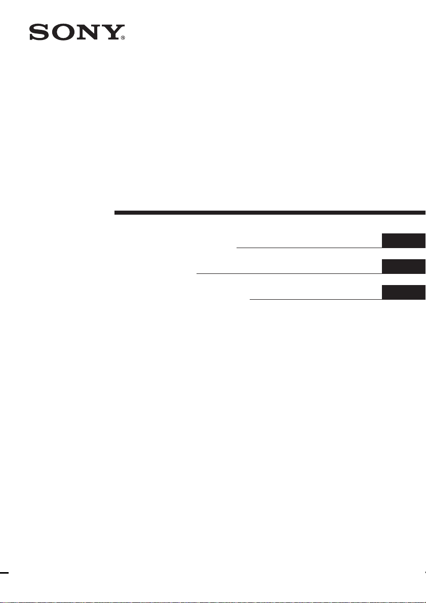
2: Connecting the control center and subwoofer
Required cords
System cord (supplied)
Control center
INPUT
COAXIALOPTICAL
DVD
Subwoofer
SAT AUX
L
R
TVVIDEO
CONTROL
Getting Started
CONTROL
FRONT R
SURR R
SPEAKERS
FRONT LCENTER
SURR L
Note
Be sure to disconnect the AC power cord before connecting or disconnecting the system cord. If you disconnect
the system cord while the power is on, the settings you made may change.
GB
5
Page 6
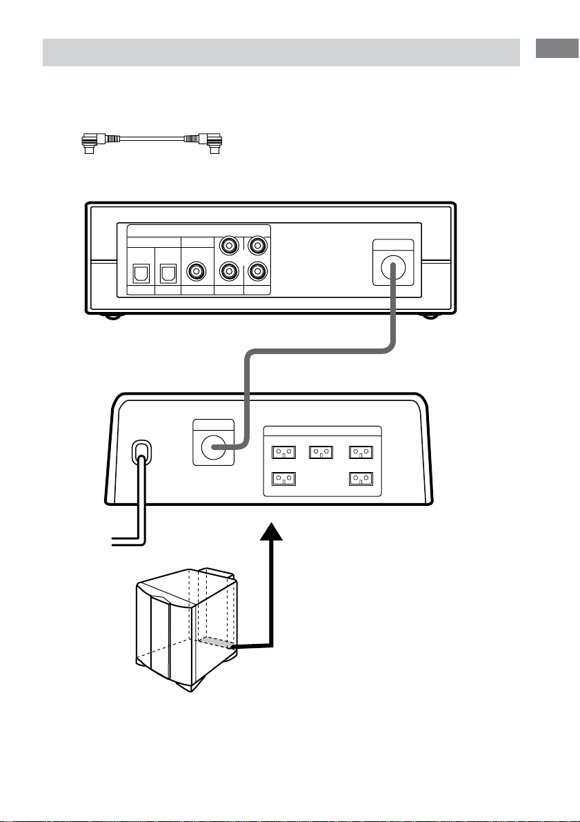
3: Connecting components with digital audio output jacks
Connect the digital audio output jacks of your DVD player or other component (“Play Station 2”, CD
player, MD deck, satellite tuner, etc.) to the control center’s digital audio input jacks to bring the
multi channel surround sound of a movie theater into your home.
Connect the video output jacks of your DVD player or “Play Station 2” to the video input jacks of
your TV.
Note
You cannot input the video signal to this system. When you connect video components (VCR, TV, etc.), connect
the video output jack of the video component to the video input jack of your TV.
Required cords
Optical digital cord (supplied)
Coaxial digital cord (not supplied)
Control center
INPUT
COAXIALOPTICAL
DVD
SAT AUX
L
R
TVVIDEO
CONTROL
OUTPUT
OPTICAL
OUT
DVD player or
“Play Station 2”
OUTPUT
OPTICAL
OUT
Satellite tuner
OUTPUT
COAXIAL
OUT
Other digital audio/video
components
(CD player, MD deck, etc.)
Tip
The digital input jacks are compatible with 32 kHz, 44.1 kHz, 48 kHz and 96 kHz sampling frequencies.
GB
6
Page 7

Setting for when you use Sony DVD player or “Play Station 2”
When you connect DVD player or “Play Station 2” as shown on the previous page, perform the
following settings on each component. For details, refer to the operating instructions supplied with
each component.
Getting Started
<DVD player>
1 Select “AUDIO SETUP” in the setup
display.
2 Set “AUDIO DRC” to “WIDE RANGE”.
3 Set “DIGITAL OUT” to “ON”.
<“Play Station 2”>
1 Select “AUDIO SETTING” in the setup
2 Select “AUDIO DIGITAL OUTPUT”.
3 Set “OPTICAL DIGITAL OUTPUT” to
4 Set “DOLBY DIGITAL” to “DOLBY
DIGITAL”.
5 Set “DTS” to “ON”.
“Play Station 2” is a trademark of Sony Computer Entertainment.
4 Set “DOLBY DIGITAL” to “ON”.
5 Set “DTS” to “ON”.
display.
“ON”.
GB
7
Page 8
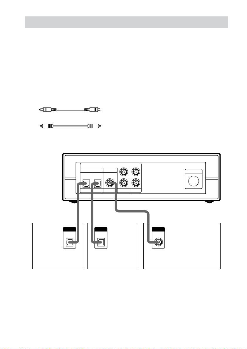
4: Connecting video components
Required cords
Audio cord (not supplied)
When connecting a cord, be sure to match the color-coded pins to the appropriate jacks on the
components; white (left) to white; and red (right) to red.
Note
You cannot input the video signal to this system. When you connect video components (VCR, TV, etc.), connect
the video output jack of the video component to the video input jack of your TV.
White (L)
Red (R)
VCR
OUTPUT
AUDIO
OUT
L
R
Control center
INPUT
COAXIALOPTICAL
DVD
SAT AUX
L
R
TVVIDEO
L
R
AUDIO
OUT
OUTPUT
CONTROL
TV monitor
GB
8
Page 9
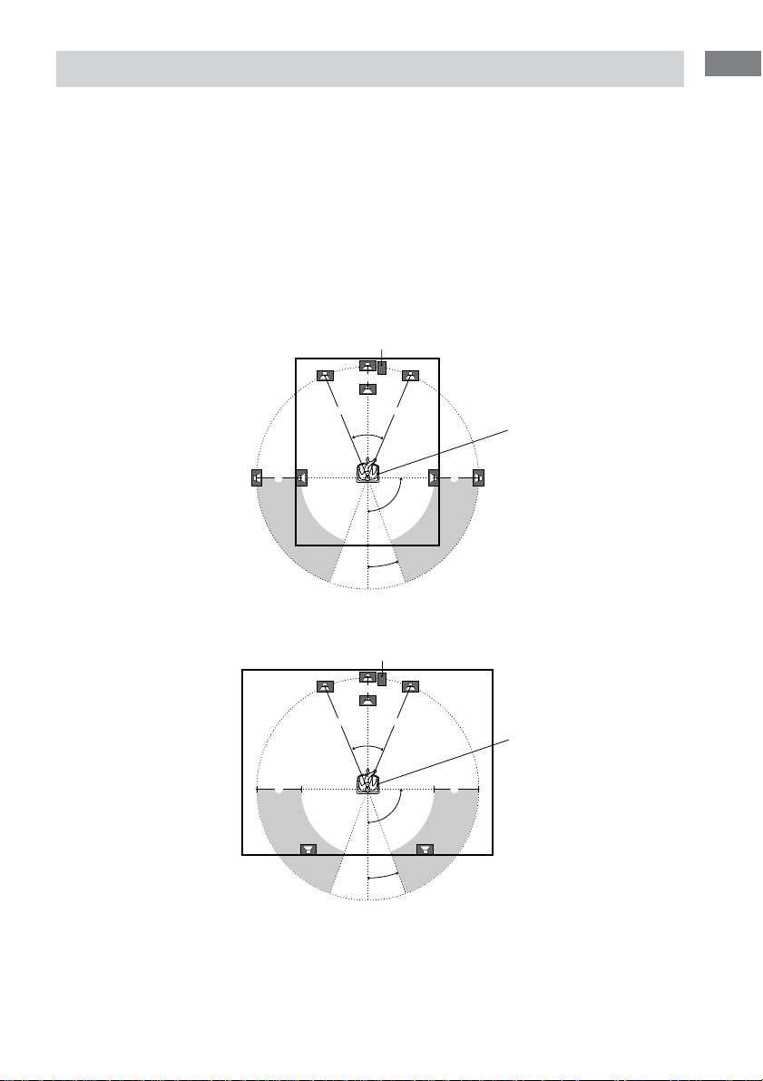
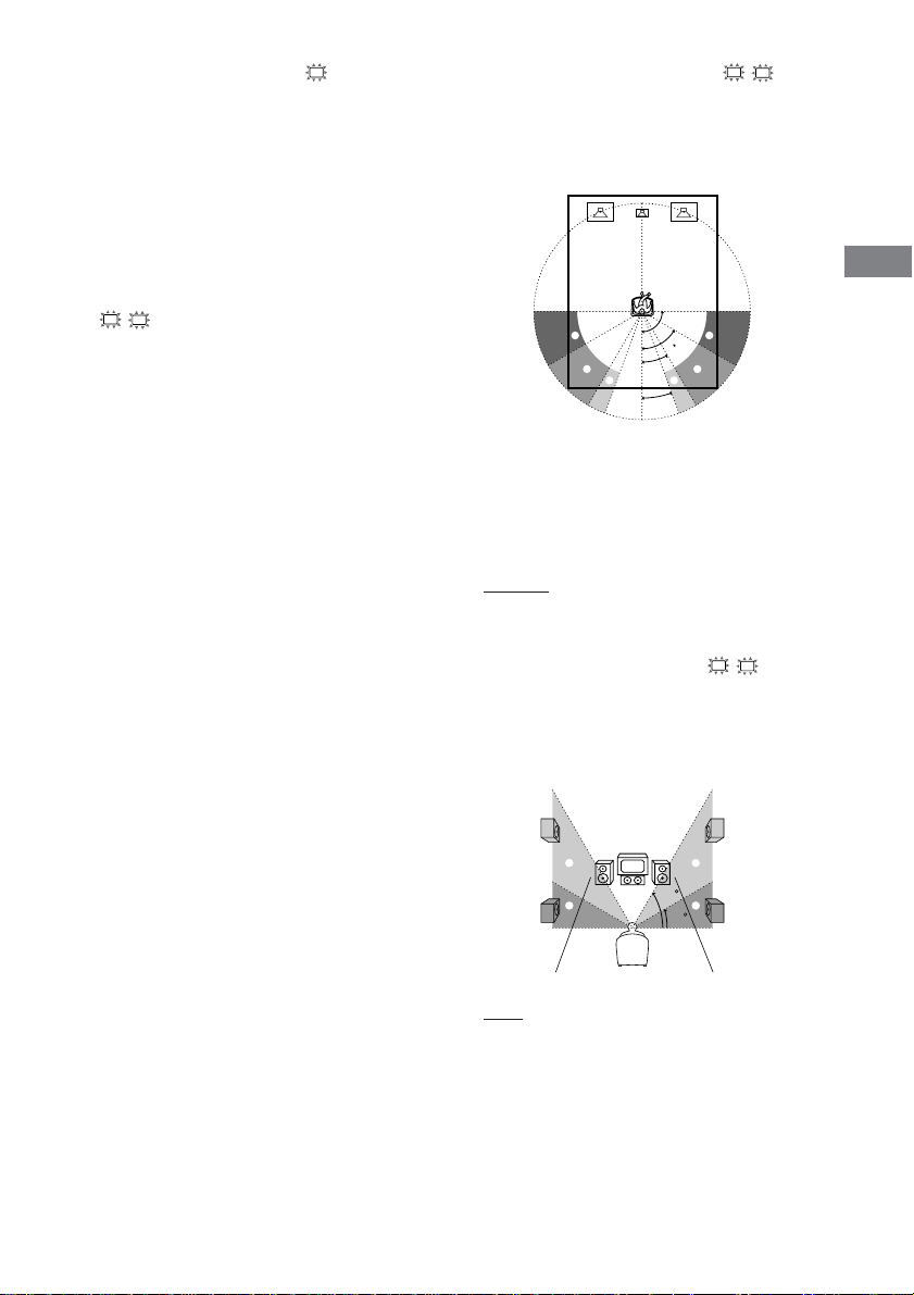
5: Placing speakers
To fully enjoy surround sound, configure your speakers as below.
• Place the front speaker in a location 1 to 10 meters from the listening position (A).
• You can enjoy a higher quality sound effect if you place the center speaker from a distance equal to the
front speaker distance (A) to a distance 1.5 meters closer to your listening position (B).
• You can enjoy a higher quality sound effect if you place the surround speakers from a distance equal to
the front speaker distance (A) to a distance 4.5 meters closer to your listening position (C).
• You can place the surround speakers either behind you or to the side, depending on the shape of your
room (etc.).
• Place the subwoofer at the same distance from the listening position as the front speaker (left or right).
When placing surround speakers to your side
Subwoofer
B
AA
45°
CC
90°
20°
Listening position
Getting Started
When placing surround speakers behind you
Subwoofer
B
AA
45°
CC
90°
20°
Note
Listening position
Do not place the center speaker and surround speakers farther away from the listening position than the front
speakers.
GB
9
Page 10
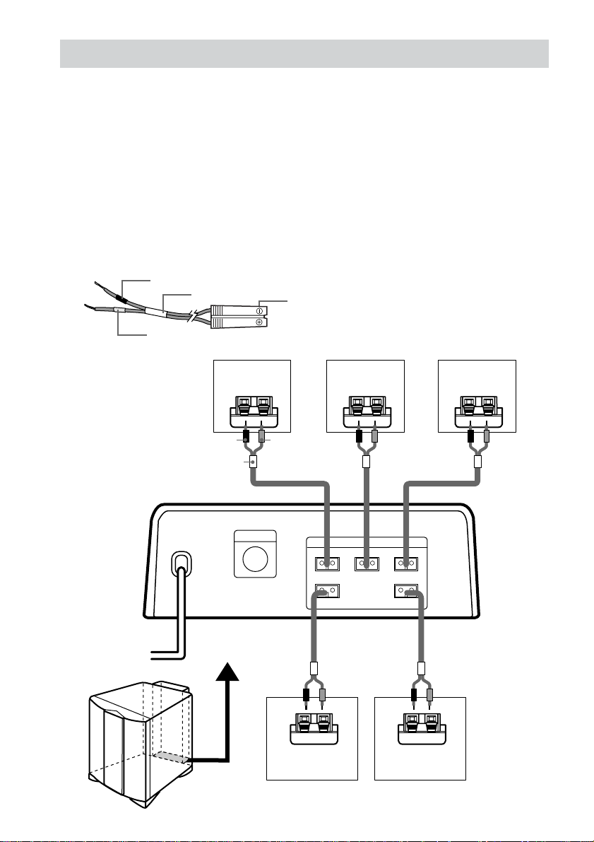
6: Connecting speakers
Connect the speakers to the SPEAKERS jacks underneath the rear of the subwoofer.
1 Stick the supplied speaker stickers (“FRONT L” etc.) on the satellite speakers.
2 Place the speakers (page 9).
3 Connect the speaker cords by matching the color of labels on the satellite speakers and
the color tubes on the speaker cords.
The connector and the color tube of the speaker cords are the same color as the label of the jacks
to be connected.
Required cords
Speaker cords (supplied)
Connect the cord with a black tube to the (–) jack.
(–)
(+)
Black tube
Red tube
Color tube
Speaker plug
Front speaker
(R)
–
Black tube (–)
Color tube Red Green White
+
Red tube (+)
Center speaker
–
+
Subwoofer
CONTROL
Gray Blue
–
Surround speaker
FRONT R
SURR R
(R)
SPEAKERS
+
FRONT LCENTER
SURR L
–
Surround speaker
(L)
Front speaker
(L)
–
+
+
10
GB
Page 11
To avoid short-circuiting the
speakers
Short-circuiting may damage the speakers and
cause a malfunction.
Make sure the stripped ends of each
speaker cord does not touch the
stripped end of another speaker cord.
Examples of poor conditions of the
speaker cord
Stabilizing speakers
To prevent speaker vibration or movement
while listening, attach the supplied foot pads at
the bottom of the speakers. If you are using the
speaker stand (not supplied), you do not need
to attach them.
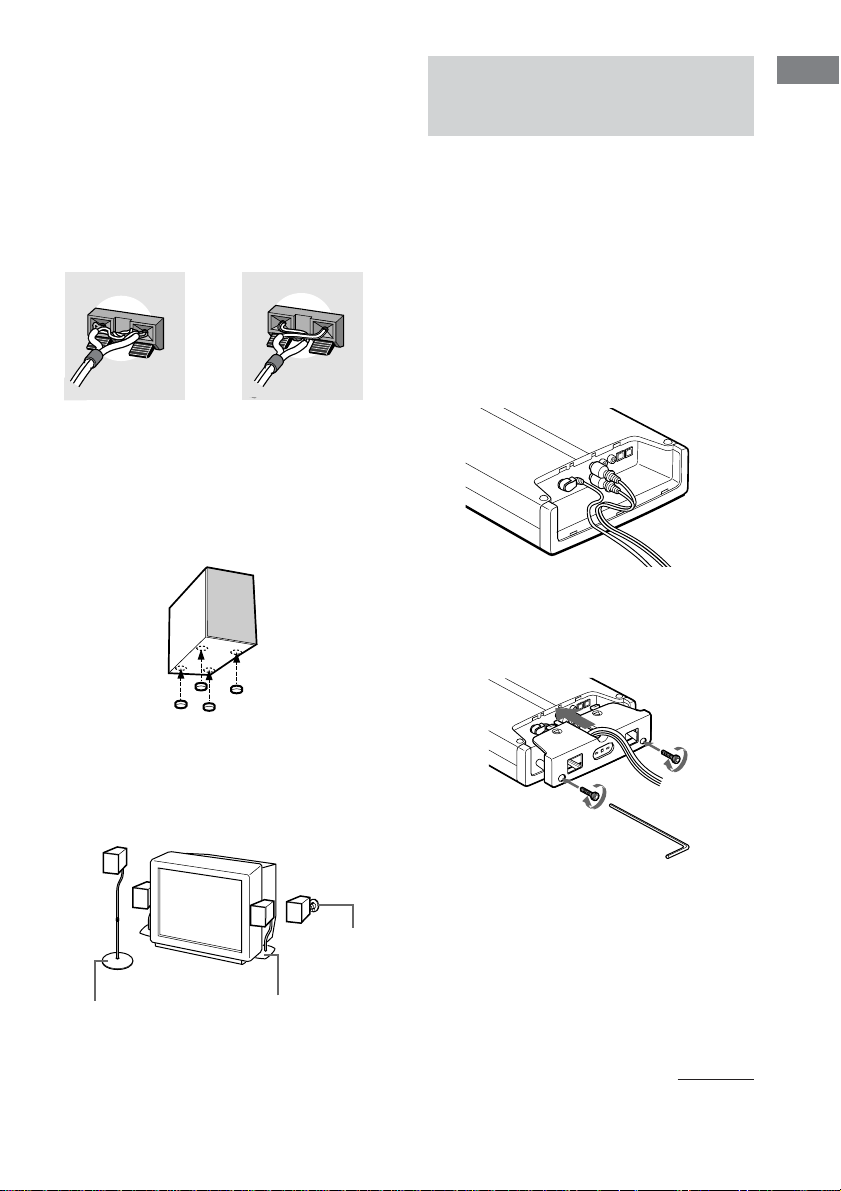
7: Attaching the jack
cover and stand
You can use the control center laid flat, or in an
upright position by attaching the supplied stand
to the rear or side of the control center. You
can also install the control center on the wall.
Besides, you can change the item layout in the
display according to the layout of the control
center (page 16).
Attaching the jack cover
1 Gather all the connecting cords
together.
2 Attach the jack cover carefully so as
not to pinch the cords. Then fix the jack
cover with the supplied screws using
the hexagonal wrench.
Getting Started
Using speaker stand (not supplied)
When using separately sold speaker stand
(WS-FV10C, WS-TV10C, WS-WV10C), you
can easily configure your speaker layout.
WS-WV10C
(Wall use)
WS-FV10C
WS-TV10C
Notes
• Make sure that the connecting cords are not trapped
by the jack cover.
• If you use commercially available cords, it is
recommended that you use cords similar in size to
the cords provided with this system. If the cords are
too thick or stiff, or the plug is too large, you may
not be able to attach the jack cover securely. If you
cannot attach the jack cover, you do not have to
attach the jack cover.
continued
11
GB
Page 12
7: Attaching the jack cover and stand
(continued)
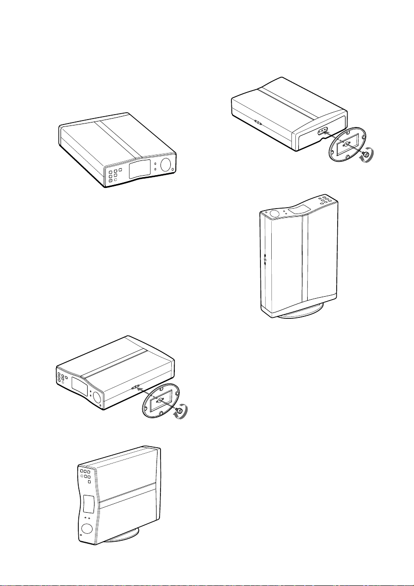
Using the control center laid
flat
Place the control center flat on a level
surface.
Note
Do not apply downward force to the control center
with the display window facing down. Doing so may
cause scratched or damage to the control center.
Using the control center in
the upright position
Make sure you attach the supplied stand.
To stand the control center on its
side
1 Attach the stand to the screw hole on
the side of the control center using the
supplied screw.
To stand the control center on its
rear
1 Attach the stand to the jack cover using
the supplied screw.
2 Place the control center upright on the
stand.
Notes
• Use the supplied stand only when you use the
control center in an upright position. Do not attach
the stand when you use the control center laid flat.
• To move the control center, hold the control center
itself. If you hold the stand, it may break.
• Do not use the control center in an upright position
without attaching the stand. If you do not attach the
stand, the control center will be unstable and may
fall over.
2 Place the control center on the stand.
GB
12
Page 13
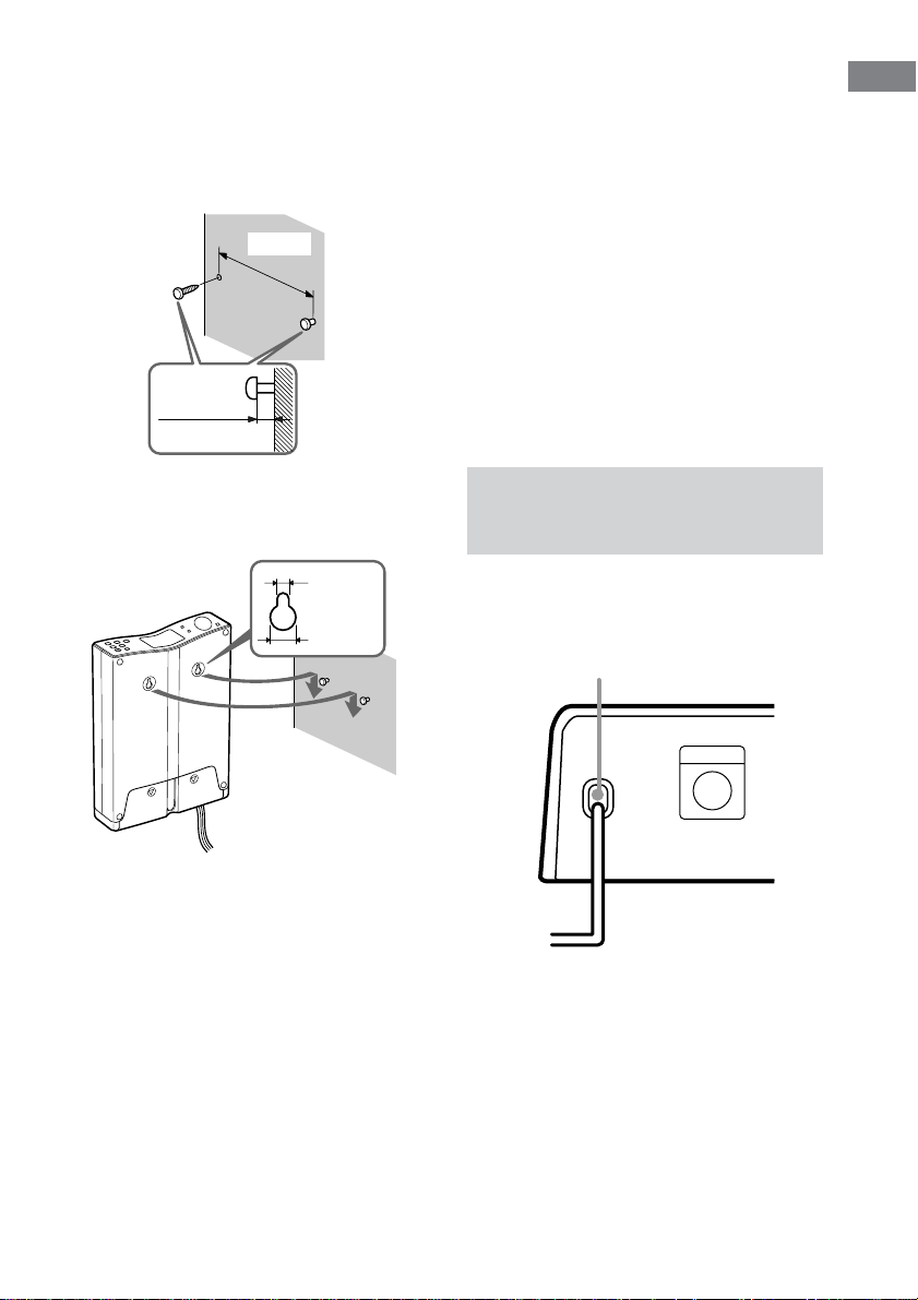
Installing the control center
on the wall
Attach the jack cover. Fasten the screws (not
supplied) to the wall at the same height 80 mm
apart. The screws should protrude by 5 to
6 mm.
80 mm
5 to 6 mm
Notes
• Use the screws that matches the wall material and
strength.
• Install the control center on a vertical and flat wall
where reinforcement is applied. Do not instal the
control center if the wall is not vertical, flat or
strong enough.
• Contact a screw shop or installer regarding the wall
material or screws to be used.
• After the control center has been used for long time
on the wall, the wall behind or above the control
center may discolor or peel off by radiation of heat
from the control center depending on the wall
material.
• Sony will refrain from any responsibility on the
accident or damage caused by improper installation,
lack of durability of the wall or screws improper
operation, natural calamity, etc.
• When you disconnect or connect the cords, take the
control center down from the wall.
Getting Started
Remove the seals covering the hanging holed.
Hang the control center on the screws. Push the
control center tightly against the wall.
4.2 mm
9.2 mm
8: Connecting the AC
power cord
After connecting the components, connect the
AC power cord of the subwoofer to a wall
outlet.
AC power cord
Subwoofer
CONTROL
b
To a wall outlet
13
GB
Page 14
Checking the connections
and settings
Performing initial setup
operations
Before using the system for the first time,
initialize the system by performing the
following procedure.
This procedure can also be used to return
settings you have made to their factory
defaults.
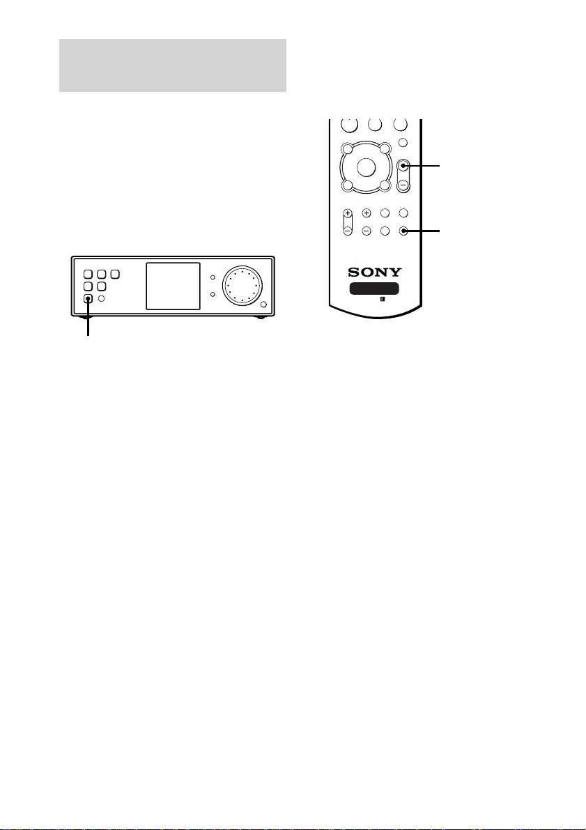
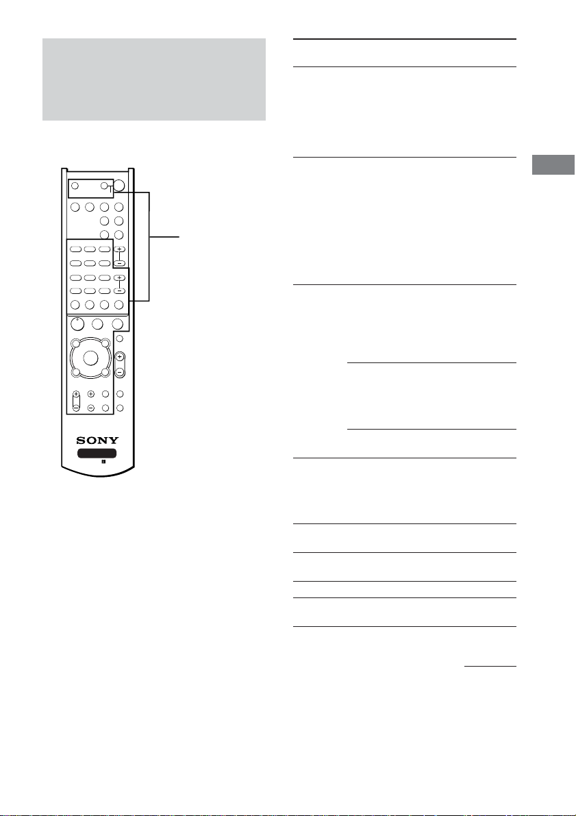
Checking if the sound comes
from all speakers
Confirm that you can hear the test tone from
each speaker.
X
F
f
RETURN/EXIT
RM-U25
AV MENU
g
O
TV/
VIDEO
WIDE TEST TONE
x
MUTING
MASTER
VOL
MAIN
MENU
MASTER VOL +
TEST TONE
N
TOP MENU/
GUIDE
G
DISPLAY
TV VOL TV CH
AV SYSTEM3
?/1
1 Press ?/1 to turn off the system.
2 Hold down ?/1 until “INITIAL” appears
in the display.
The current function name appears.
The following are reset to their factory
settings.
• All settings in the SET UP and LEVEL
menus.
• The sound field memorized for each
function.
1 Press MASTER VOL +.
(Optimal volume level: Between 20–30.)
2 Press TEST TONE.
You will hear the test tone from each
speaker in sequence.
Front (left) t Center t Front (right) t
Surround (right) t Surround (left) t
Subwoofer
While outputting the test tone, if no sound
comes from the speakers or the test tone is
output from the speaker whose name is not
displayed in the display, there is a shortcircuiting or the connection is wrong. In this
case, check the speaker connection again.
3 Press TEST TONE again to turn off the
test tone.
14
GB
Page 15
Playing a DVD on the
connected DVD player
(not supplied)
When you connect a DVD player or “Play
Station 2” and a TV, you can enjoy DVDs.
SYSTEM STANDBY
;
FM MODE
D.TUNING
?/1
SLEEP
SAT TV
AUX TUNER
PL/PLII AUTO DEC
SOUND
FIELD
PRESET/
CH/D.SKIP
TV ?/1 AV ?/1
VIDEO DVD
DVD
AAC
BI-LING
123
AUDIO ANGLE SUBTITLE
456
TIME SWAP JUMP
789
1 Press DVD.
2 Select the video input for your TV.
For details, refer to the instructions supplied
with your TV.
3 Place a DVD in your DVD player or
“Play Station 2”.
4 Start playing the DVD.
Listening to the Sound of Connected
Components
Selecting the component
You can select Sony components only.
1 Press one of the function buttons.
To select Press
DVD player or DVD
“Play Station 2”
Satellite tuner SAT
An audio/video AUX
component
(CD player, MD deck, etc.)
VCR VIDEO
TV TV
2 Turn on the component and start
playback.
When you select a component which is also
connected to the TV (such as VCR or DVD
player), turn on the TV and set the TV’s
video input to match the component you
selected.
3 Press MASTER VOL +/– to adjust the
volume.
To mute the sound
Press MUTING.
Listening to the Sound of Connected Components
15
GB
Page 16
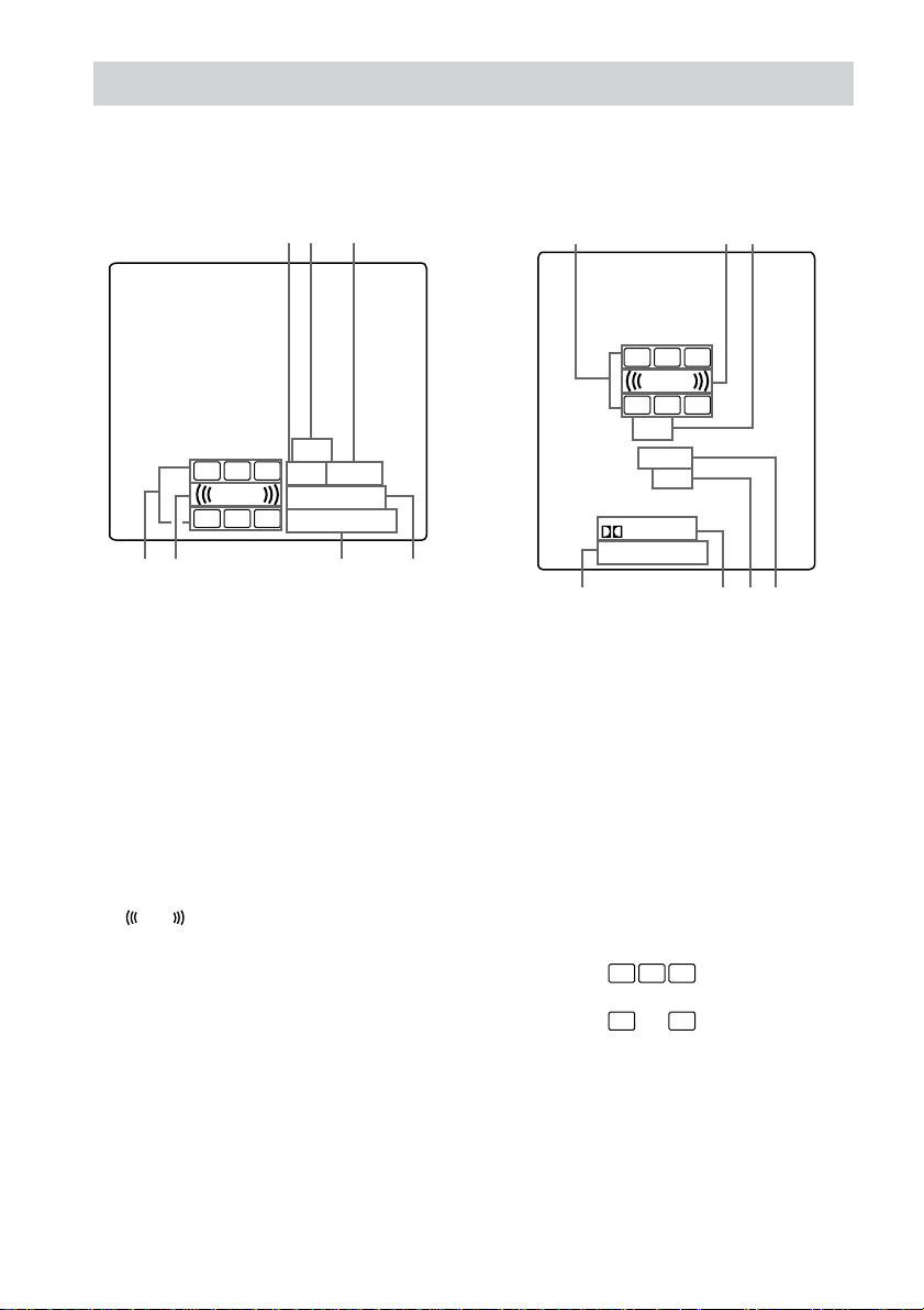
About the indications in the display
You can change the item layout in the display according to the layout of the control center (page 11).
A Horizontal display
12 3
DTS
L C R
L.F.E.
LS S RS
76
1 OPT: Lights up when DVD or SAT function
is selected.
2 DTS: Lights up when DTS signals are input.
3 COAX: Lights up when AUX function is
selected.
4 ; DIGITAL: Lights up when the control
center is decoding signals recorded in the
Dolby Digital format.
5 PRO LOGIC (II): Lights up when the system
applies Pro Logic or Pro Logic (II)
processing.
L.F.E.
6
: Lights up when the disc being
played back contains the LFE (Low
Frequency Effect) channel and when the
sound of the LFE channel signal is actually
being reproduced.
COAX
OPT
DIGITAL
a
PRO LOGIC II
45
B Vertical display
762
L C R
L.F.E.
LS
S RS
DTS
COAX
OPT
DIGITAL
PRO LOGIC II
5413
7 Playback channel indicators: The letters
light up to indicate the channels being played
back.
L (Front Left), R (Front Right), C (Center
(monaural)), LS (Surround Left), RS
(Surround Right), S (Surround (monaural or
the surround components obtained by Pro
Logic processing))
The boxes around the letters light up to
indicate the speakers used to playback the
channels.
Example:
Recording format (Front/Surround): 3/2
Sound Field: AUTO DECODING.
L C R
LS RS
16
GB
Page 17

Switching the display
(vertical/horizontal/off)
You can switch the display as follows
depending on how you place the control center
(page 11).
Control center Display
layout
Laid flat Horizontal (A on page 16,
POSN.H)
Upright (on the side) Vertical (B on page 16,
POSN.V)
Upright (on the rear) Off (POSN.U)
On the wall
To set the horizontal or vertical
display
1 Press MAIN MENU repeatedly to select
SET UP menu.
2 Move the V/v/B/b button up or down
until one of the display setting appears
in the display.
3 Move the V/v/B/b button to left or
right to select the setting type.
Select “POSN.H” to set to horizontal, select
“POSN.V” to set to vertical, and select
“POSN.U” to turn off the display.
Listening to the Sound of Connected Components
17
GB
Page 18

Enjoying Surround Sound
Selecting a sound field
You can take advantage of surround sound
simply by selecting one of the system’s
pre-programmed sound fields. They bring the
exciting and powerful sound of movie theaters
and concert halls into your home.
Press SOUND FIELD +/– repeatedly to
select the sound field you want.
The selected sound field appears in the display.
Sound field list Display
AUTO DECODING AUTO DEC
NORMAL SURROUND NORM.SUR
CINEMA STUDIO EX A DCS C.S.EX A
CINEMA STUDIO EX B DCS C.S.EX B
CINEMA STUDIO EX C DCS C.S.EX C
LARGE HALL L.HALL
SMALL HALL S.HALL
JAZZ CLUB JAZZ
LIVE CONCERT CONCERT
GAME GAME
About DCS (Digital Cinema Sound)
Sound fields with DCS marks use DCS
technology.
DCS is the concept name of the surround
technology for home theater developed by
Sony. DCS uses the DSP (Digital Signal
Processor) technology to reproduce the sound
characteristics of an actual cinema cutting
studio in Hollywood.
When played at home, DCS will create a
powerful theater effect that mimics the artistic
combination of sound and action as envisioned
by the movie director.
Enjoying movies using the
CINEMA STUDIO EX modes
CINEMA STUDIO EX modes are suitable for
watching motion picture DVDs (etc.), with
multi channel surround effects. You can
reproduce the sound characteristics of Sony
Pictures Entertainment’s dubbing studio in
your home.
There are three CINEMA STUDIO EX modes.
x CINEMA STUDIO EX A DCS
Reproduces the sound characteristics of the
Sony Pictures Entertainment “Cary Grant
Theater” cinema production studio. This is a
standard mode, great for watching most any
type of movies.
x CINEMA STUDIO EX B DCS
Reproduces the sound characteristics of the
Sony Pictures Entertainment “Kim Novak
Theater” cinema production studio. This mode
is ideal for watching science-fiction or action
movies with lots of sound effects.
x CINEMA STUDIO EX C DCS
Reproduces the sound characteristics of the
Sony Pictures Entertainment scoring stage.
This mode is ideal for watching musicals or
films where orchestra music is featured in the
soundtrack.
18
GB
Page 19
About CINEMA STUDIO EX modes
The CINEMA STUDIO EX modes consist of
the following three elements.
• Virtual Multi Dimension
Creates 5 sets of virtual speakers from a single
pair of actual surround speakers.
• Screen Depth Matching
Creates the sensation that the sound is coming
from inside the screen like in theaters.
• Cinema Studio Reverberation
Reproduces the type of reverberation found in
theaters.
The CINEMA STUDIO EX modes integrate
these three elements simultaneously.
Tip
You can identify the encoding format of DVD
software, etc. by looking at the logo on the package.
– : Dolby Digital discs
– : Dolby Surround encoded programs
– : DTS Digital Surround encoded programs
Notes
• The effects provided by the virtual speakers may
cause increased noise in the playback signal.
• When listening with sound fields that employ the
virtual speakers, you will not be able to hear any
sound coming directly from the surround speakers.
Selecting other sound fields
Press SOUND FIELD +/– repeatedly to
select the sound field you want.
The selected sound field appears in the display.
x AUTO DECODING
Automatically detects the type of audio signal
being input (Dolby Digital, DTS, or standard 2
channel stereo) and performs the proper
decoding if necessary. This mode presents the
sound as it was recorded/encoded, without
adding any effects (ex. reverberation).
x NORMAL SURROUND
Software with multi channel surround audio
signals is played back according to the way it
was recorded. This sound field reproduces the
acoustics of a small rectangular concert hall.
For software with 2 channel audio signals, you
can select from a variety of decoding modes
according to the 2 channel decoding mode
setting.
x LARGE HALL
Reproduces the acoustics of a large rectangular
concert hall.
x SMALL HALL
Reproduces the acoustics of a small rectangular
concert hall.
x JAZZ CLUB
Reproduces the acoustics of a jazz club.
x LIVE CONCERT
Reproduces the acoustics of a 300-seat live
house.
x GAME
Obtains maximum audio impact from TV game
software.
Enjoying Surround Sound
19
GB
Page 20

Other Operations/Settings
Enjoying Dolby Pro Logic (II)
This function lets you specify the type of
decoding for 2 channel audio sources.
This system can reproduce 2 channel sound in
4 channels through Dolby Pro Logic; or 5.1
channels through Dolby Pro Logic II.
Press ;PL/PLII repeatedly to select the 2
channel decoding mode.
The selected mode appears in the display. The
sound field automatically switches to
“NORM.SUR” (page 19).
Dolby Pro Logic/ Display
Dolby Pro Logic II mode
DOLBY PRO LOGIC DOLBY PL
Sources recorded in 2 channels
are decoded and played back in
4 channels. This is ideal for
playback of video tapes encoded
in Dolby Pro Logic.
DOLBY PRO LOGIC II MOVIE MOVIE
Sources recorded in 2 channels,
as well as all stereo sound sources
are played back in 5.1 channels.
This is ideal when watching movies.
DOLBY PRO LOGIC II MUSIC MUSIC
Normal stereo sources such as CDs
are played back in 5.1 channels.
This is ideal for music playback.
Using the Sleep Timer
You can set the system to turn off
automatically at a specified time.
Press SLEEP while holding down ALT.
Each time you press the button, the display
changes cyclically as follows:
2-00-00 t 1-30-00 t 1-00-00 t 0-30-00
t OFF
While using Sleep Timer, the display dims.
Tip
To check the remaining time before the system turns
off, press SLEEP while holding down ALT. The
remaining time appears in the display.
20
GB
Page 21
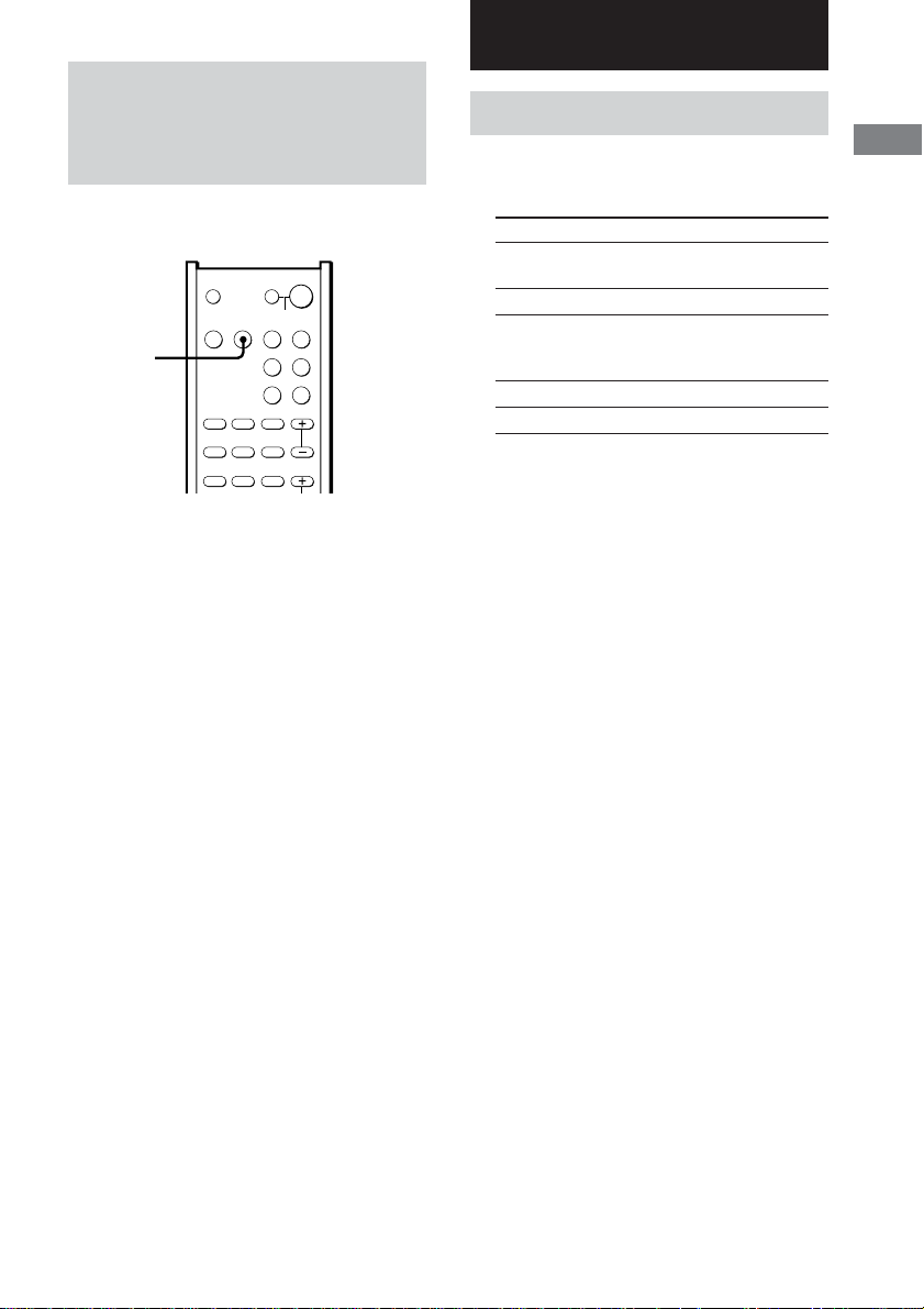
Using the supplied remote
to controlling the other
component
You can use the supplied remote to control
other Sony components.
SYSTEM STANDBY
SAT TV
AUX TUNER
;
PL/PLII AUTO DEC
FM MODE
D.TUNING
123
456
789
MEMORY SHIFT
>
0/10 >10/11 ENTER/12
–
+
TUNING DISC ALT
-
M
CLEAR
SEARCH MODE
X
N
AV MENU
F
G
g
f
O
RETURN/EXIT
TV/
VIDEO
WIDE TEST TONE
AV SYSTEM3
RM-U25
?/1
SLEEP
SOUND
FIELD
PRESET/
CH/D.SKIP
x
MUTING
MASTER
VOL
MAIN
MENU
Remote buttons for
operating other
components
TV ?/1 AV ?/1
VIDEO DVD
AAC
BI-LING
AUTO ANGLE SUBTITLE
TIME SWAP JUMP
.
m
ANT
TOP MENU/
GUIDE
DISPLAY
TV VOL TV CH
Remote Operations Function
Button
AV ?/1 TV/VCR/ Turns the audio and
CD player/ video components on or
VCD player/ off.
LD player/
DVD player/
MD deck/
DAT deck
SYSTEM
Control center/
Turns off the system and
STANDBY TV/VCR/ other Sony audio/video
(Press
Satellite tuner/
components.
AV ?/1 CD player/
while VCD player/
holding LD player/
down ?/1) DVD player/
MD deck/
DAT deck/
Tape deck
1–9 and Tuner Use with “SHIFT” button
0/10 to select tuner preset
(After station numeric input
pressing during DIRECT
ALT) TUNING or MEMORY
mode.
CD player/ Selects track numbers.
VCD player/ 0 selects track 10.
LD player/
MD deck/
DAT deck
TV/VCR/ Selects channel numbers.
Satellite tuner
SHIFT Tuner Press repeatedly to select
a memory page for
presetting radio stations
or tuning to preset
stations.
D.TUNING Tuner Tuner station direct key-
in-mode.
TUNING Tuner Scans radio stations.
+/–
MEMORY Tuner Stores the radio stations.
FM MODE Tuner Selects FM monaural or
stereo reception.
Other Operations/Settings
continued
21
GB
Page 22

Using the supplied remote to controlling
the other component (continued)
Remote Operations Function
Button
>10/11 CD player/ Selects track numbers
(After VCD player/ over 10.
pressing LD player/MD
ALT) deck/Tape deck
TV Selects channel 11.
AUDIO TV/VCR/ Changes the sound to
TIME CD player/ Shows the time or
PRESET/ Tuner Scans and selects preset
CH/ stations.
D.SKIP +/– TV/VCR/ Selects preset channels.
ENTER/12 TV/VCR/ After selecting a channel,
(After
pressing
ALT)
DISC CD player/ Selects a disc directly
DISPLAY TV/VCR/ Selects information
ANT VCR Selects output signal
DVD player Multiplex, Bilingual or
VCD player/ displays the playing time
DVD player of disc, etc.
satellite tuner
CD player/ Skips discs (multi-disc
VCD player/ changer only).
DVD player/
MD deck
satellite tuner/
LD player/
MD
deck/ enter the value.
DAT deck/
Tape deck
TV Selects channel 12.
VCD player (multi-disc changer
VCD player/ displayed on the TV
LD player/ screen.
DVD player
Multi channel TV Sound.
disc or track using the
numeric buttons, press to
only).
from aerial terminal: TV
signal or VCR program.
Remote Operations Function
Button
./> VCR/ Skips tracks.
CD player/
VCD player/
LD player/
DVD player/
MD deck/
DAT deck/
Tape deck
m/M CD player/ Searches tracks
VCD player/ (forward or backward).
DVD player/
LD player/
MD deck
VCR/ Fast forwards or
DAT deck/ rewinds.
Tape deck
H VCR/ Starts play.
CD player/
VCD player/
LD player/
DVD player/
MD deck/
DAT deck/
Tape deck
X VCR/ Pauses play or record.
CD player/ (Also starts recording
VCD player/ with components in
LD player/ record standby.)
DVD player/
MD deck/
DAT deck/
Tape deck
x VCR/ Stops play.
CD player/
VCD player/
LD player/
DVD player/
MD deck/
DAT deck/
Tape deck
AV MENU VCR/Satellite Displays menu.
tuner/
DVD player
V/v/B/b VCR/Satellite Selects a menu item.
tuner/ Press to enter the
DVD player selection.
22
GB
Page 23

Remote Operations Function
Button
RETURN O
EXIT
SUBTITLE
ANGLE DVD player To select viewing angle
CLEAR DVD player Press if you made a
SEARCH DVD player Select searching mode.
MODE Press to select the unit for
TOP MENU/
GUIDE Satellite tuner Displays guide menu.
TV ?/1 TV Turns the TV on or off.
-/-- TV Selects the channel entry
TV VOL TV Adjust the volume of the
+/– TV.
TV CH +/– TV Select preset TV
TV/ TV Selects input signal: TV
VIDEO input or video input.
SWAP* TV Swaps the small and
JUMP TV Toggles between the
ALT Remote Change remote key
/VCD player/ Returns to the previous
LD player/ menu.
DVD player
Satellite Exits the menu.
tuner
DVD player Changes the subtitles.
or changes the angles.
mistake when you press
the number button or
press to return to the
continuous play etc.
search (track, index, etc.)
DVD player Displays DVD title.
mode, either one or two
digit.
channels.
large picture.
previous and the current
channels.
function to activate those
buttons with orange
printing.
Notes
• The above explanation is intended to serve as an
example only.
Therefore, depending on the component the above
operation may not be possible or may operate
differently than described.
• To activate the buttons with orange printing, press
ALT first before pressing the buttons.
• Before you use the V/v/B/b button for control
center operation, press MAIN MENU. To operate
other components, press TOP MENU/GUIDE or
AV MENU after pressing the function button.
Other Operations/Settings
* Only for Sony TVs with the picture-in-picture
function.
23
GB
Page 24

Changing the factory
Setting up the speakers
setting of a function button
on the remote
If the factory settings of the function buttons
the remote
components, you can change them. For
example, if you have an MD player and you do
not have a DVD player, you can assign the
DVD button to your MD deck.
1 Hold down one of the function buttons
2 Press the corresponding button of the
do not match your system
on the remote (VIDEO/DVD/SAT/TV/
AUX/TUNER) whose function you want
to change.
Example: Hold down DVD.
component you want to assign to the
Function button.
Example: Press m (for MD deck).
The following buttons are assigned to select
the functions:
To operate Press
VCR (command mode VTR 1*) 1
VCR (command mode VTR 2*) 2
VCR (command mode VTR 3*) 3
DVD player 4
TV 5
DSS (Digital Satellite Receiver) 6
Tuner 0/10
CD player 12
MD deck m
LD player M
Use the SET UP menu to set the types of the
speakers connected to the subwoofer.
1 Press MAIN MENU repeatedly to select
on
SET UP menu.
2 Move the V/v/B/b button up or down
to select the parameter.
3 Move the V/v/B/b button to left or
right to select the setting.
4 Repeat steps 2 and 3 to adjust the other
parameters.
Speaker setup parameters
The initial setting is underlined.
x Front speaker distance (L R DIS.)
Initial setting: 3.5 m
Lets you set the distance from your listening
position to the front speakers (A on page 9).
You can adjust from 1.0 meter to 10.0 meters
in 0.1 meter steps.
If both front speakers are not placed an equal
distance from your listening position, set the
distance to the closest speaker.
* Sony VCRs are operated with a VTR 1, 2 or 3
setting. These correspond to Beta, 8mm and
VHS respectively.
To reset all the function buttons to
their factory setting
Press ?/1, AV ?/1 and MASTER VOL – at
the same time.
GB
24
Page 25
x Center speaker distance (C DIS.)
60
30
A
B
A
B
Initial setting: 3.5 m
Lets you set the distance from your listening
position to the center speaker. You can enjoy a
higher quality sound effect if you place the
center speaker from a distance equal to the
front speaker distance (A on page 9) to a
distance 1.5 meters closer to your listening
position (B on page 9).
x Surround speaker distance
(LS RS DIS.)
Initial setting: 2.0 m
Lets you set the distance from your listening
position to the surround speakers. You can
enjoy a higher quality sound effect if you place
the surround speakers from a distance equal to
the front speaker distance (A on page 9) to a
distance 4.5 meters closer to your listening
position (C on page 9).
If both surround speakers are not placed an
equal distance from your listening position, set
the distance to the closest speaker.
x Surround speaker position (LS RS PL.)*
Lets you specify the location of your surround
speakers for proper implementation of the
surround effects in the Cinema Studio EX
modes (page 18).
90°
A
B
C C
A
60°
30°
B
20°
• SIDE
Select if the location of your surround speakers
corresponds to section A.
• MIDDLE (MID.)
Select if the location of your surround speakers
corresponds to section B.
• BEHIND (BEHD.)
Select if the location of your surround speakers
corresponds to section C.
x Surround speaker height (LS RS HGT.)*
Lets you specify the height of your surround
speakers for proper implementation of the
surround effects of the Cinema Studio EX
modes (page 18).
Other Operations/Settings
• LOW
Select if the height of your surround speakers
corresponds to section A.
• HIGH
Select if the height of your surround speakers
corresponds to section B.
25
GB
Page 26

Customizing sound fields
By adjusting the surround and level parameters,
you can customize the sound fields to suit your
particular listening situation.
Position your speakers and do the procedures
described in “Placing speakers” (page 9) and
“Checking if the sound comes from all
speakers” (page 14) before you customize a
sound field.
Adjusting the surround
parameter (EFFECT)
This parameter lets you adjust the “presence”
of the current surround effect. This effect is
available for the sound fields except for AUTO
DECODING and NORMAL SURROUND.
Initial setting: (depends on sound field)
1 Start playing a source encoded with
multi channel surround effects (DVD,
etc.)
2 Press MAIN MENU repeatedly to select
EFFECT.
3 Move the V/v/B/b button to left or
right to select the setting.
Adjusting the speaker level
and balance
You can adjust the balance and level of each
speaker. Sit in the listening position, then
adjust the test tone to sound the same level.
These settings are applied to all sound fields.
1 Press MASTER VOL +.
(Optimal volume level: Between 20–30.)
2 Press TEST TONE.
You will hear the test tone from each
speaker in sequence.
Front (left) t Center t Front (right) t
Surround (right) t Surround (left) t
Subwoofer
3 Press MAIN MENU repeatedly to select
LEVEL menu.
4 Move the V/v/B/b button up or down
to select the parameter.
5 Move the V/v/B/b button to left or
right to select the setting.
6 Repeat steps 4 and 5 to adjust the other
parameters.
Tips
• To make more precise adjustment, start playing a
source encoded with multi channel surround effects
(DVD, etc.), then adjust the level and balance while
listening to the source.
• The system employs a test tone with a frequency
centered at 800 Hz.
• You can adjust the level of all speakers at the same
time. Turn MASTER VOLUME on the control
center or press MASTER VOL +/– on the remote.
Notes
• The front balance, surround balance, center level,
surround level, and subwoofer level are shown in
the display during adjustment.
• To enjoy the better sound quality, do not turn the
volume of the subwoofer too high.
26
GB
Page 27

LEVEL menu parameters
x Front speaker balance (L R BAL.)
Initial setting: midpoint (BALANCE)
Lets you adjust the balance between front left
and right speakers. You can adjust from L (+1
– +8) to R (+1 – +8) in 1 increment steps.
x Surround speaker balance (LS RS BAL.)
Initial setting: midpoint (BALANCE)
Lets you adjust the balance between surround
left and right speakers. You can adjust from L
(+1 – +8) to R (+1 – +8) in 1 increment steps.
x Center speaker level (CTR)
Initial setting: 0 dB
You can adjust from –10 dB to +10 dB in 1 dB
steps.
x Surround speaker level (SURR)
Initial setting: 0 dB
You can adjust from –10 dB to +10 dB in 1 dB
steps.
x Subwoofer level (S.W.)
Initial setting: 0 dB
You can adjust from –10 dB to +10 dB in 1 dB
steps.
x LFE (Low Frequency Effect) mix level
LFE
(
LFE)
Initial setting: 0 dB
Lets you attenuate the level of the LFE (Low
Frequency Effect) channel output from the
subwoofer without effecting the level of the
bass frequencies sent to the subwoofer from the
front, center or surround channels via the
Dolby Digital or DTS bass redirection
circuitry. You can adjust from –20 dB to 0 dB
(line level) in 1 dB steps. “0 dB” outputs the
full LFE signal at the mix level determined by
the recording engineer. When set to “OFF”, the
sound of the LFE channel from the subwoofer
is muted. In this case, the low frequency sounds
of the front, center, or surround speakers are
output from the subwoofer.
x Dynamic range compressor (DRC.)
Lets you compress the dynamic range of the
sound track. This may be useful when you want
to watch movies at low volumes late at night.
• OFF
The dynamic range is not compressed.
• STD
The dynamic range is compressed as intended
by the recording engineer.
• MAX
The dynamic range is compressed dramatically.
Tip
Dynamic range compressor lets you to compress the
dynamic range of the soundtrack based on the
dynamic range information included in the Dolby
Digital signal. “STD” is standard compression, but
because many sources have only light compression,
we recommend using the “MAX” setting. This greatly
compresses the dynamic range and lets you view
movies late at night at low volumes. Unlike analog
limiters, the levels are predetermined and provide a
very natural compression.
Note
Dynamic range compression is possible with Dolby
Digital sources only.
Other Operations/Settings
27
GB
Page 28

Additional Information
Precautions
On safety
Should any solid object or liquid fall into the cabinet,
unplug the control center and have it checked by
qualified personnel before operating it any further.
On power sources
• Before operating the unit, check that the operating
voltage is identical with your local power supply.
The operating voltage is indicated on the nameplate
at the rear of the subwoofer.
• The unit is not disconnected from the AC power
source (mains) as long as it is connected to the wall
outlet, even if the control center itself has been
turned off.
• If you are not going to use the system for a long
time, be sure to disconnect the subwoofer from the
wall outlet. To disconnect the AC power cord,
grasp the plug itself; never pull the cord.
• AC power cord must be changed only at the
qualified service shop.
On heat buildup
Although the unit heats up during operation, this is
not a malfunction. If you continuously use this unit at
a large volume, the cabinet temperature of the top,
side and bottom rises considerably. To avoid burning
yourself, do not touch the cabinet.
On placement
• Place the subwoofer in a location with adequate
ventilation to prevent heat buildup and prolong the
life of the subwoofer.
• Do not place the control center and subwoofer near
heat sources, or in a place subject to direct sunlight,
excessive dust or mechanical shock.
• Do not place anything on top of the cabinet that
might block the ventilation holes and cause
malfunctions.
• Use caution when placing the subwoofer or a
speaker stand (not supplied) that is attached with
the front/rear speakers on a specially treated
(waxed, oiled, polished, etc.) floor, as staining or
discoloration may result.
On operation
Before connecting other components, be sure to turn
off and unplug the AC power cord of the subwoofer.
On cleaning
Clean the cabinet, panel and controls with a soft cloth
slightly moistened with a mild detergent solution. Do
not use any type of abrasive pad, scouring powder or
solvent such as alcohol or benzine.
Troubleshooting
If you experience any of the following
difficulties while using the control center, use
this troubleshooting guide to help you remedy
the problem. Should any problem persist,
consult your nearest Sony dealer.
When bringing the system in for repairs, be
sure to bring in the entire system (control
center and subwoofer). This product is system
product, and the entire system is needed to
determine the location requiring repair.
The multi channel surround effect of the Dolby
Digital or DTS is not obtained.
• Check that the DVD software, etc. is recorded in
Dolby Digital or DTS.
• If you connect the DVD player, etc. to the digital
input jack on this system, check the audio setting
(for digital audio output) of the component (page
7).
• Check that the audio track is correctly selected
on the DVD player. (Check the audio setting of
the DVD menu.)
There is no sound or only a very low-level sound
is heard.
• Check that the speakers and components are
connected securely.
• Check that you have selected the correct
component on the control center.
• Press MUTING if muting function is activated.
The left and right sounds are unbalanced or
reversed.
• Check that the speakers and components are
connected correctly and securely.
• Adjust balance parameters in the LEVEL menu.
There is severe hum or noise.
• Check that the speakers and components are
connected securely.
• Check that the connecting cords are away from a
transformer or motor, and at least 3 meters away
from a TV set or fluorescent light.
• Move your TV away from the audio components.
• The plugs and jacks are dirty. Wipe them with a
cloth slightly moistened with alcohol.
If you have any question or problem concerning your
system, please consult your nearest Sony dealer.
GB
28
Page 29

There is no sound from the center speaker.
• If you connect the DVD player, etc. to the digital
input jack on this system, check the audio setting
(for digital audio output) of the component (page
7).
• Make sure the sound field function is on (press
SOUND FIELD +/–).
• Select the CINEMA STUDIO EX mode (page
18).
• Adjust the speaker level (page 26).
There is no sound or only a very low-level sound
is heard from the surround speakers.
• If you connect the DVD player, etc. to the digital
input jack on this system, check the audio setting
(for digital audio output) of the component (page
7).
• Make sure the sound field function is on (press
SOUND FIELD +/–).
• Select the CINEMA STUDIO EX mode (page
18).
• Adjust the speaker level (page 26).
The surround effect cannot be obtained.
• Make sure the sound field function is on (press
SOUND FIELD +/–).
The remote does not function.
• Point the remote at the remote sensor on the
control center.
• Remove any obstacles in the path between the
remote and the control center.
• Replace both batteries in the remote with new
ones, if they are weak.
• Make sure you select the correct function on the
remote.
When the following message
appears in the display
“UNLOCK”
• You select DVD, AUX or SAT as the function
and no component is connected to the digital
input jacks.
• The component is correctly connected, but the
component is turned off or the playback has not
started.
“PROTECT”
• The speaker cords are short-circuited (page 11).
p Turn off the power, then reconnect the
speaker cords correctly.
• The system heats up because the system was
used for a long time with loud volume.
p Turn off the power and leave the system for a
while.
p Turn down the volume.
Reference sections for clearing the
system’s memory
To clear See
All memorized settings page 14
Additional Information
29
GB
Page 30
Specifications
Amplifier/subwoofer section
POWER OUTPUT
Rated Power Output at Stereo mode
(6 ohms 1 kHz, THD 0.7 %)
Reference Power Output
(THD 0.7 %) Front*: 40 W/ch
* Depending on the sound field settings and the
source, there may be no sound output.
Frequency response
Inputs (Digital)
AUX (Coaxial) Impedance: 75 ohms
DVD, SAT (Optical) S/N: 90 dB
Inputs (Analog)
TV, VIDEO Sensitivity: 700 mV
Enclosure type Advanced S.A.W.
Speaker unit 16 cm cone type
Rated frequency range
High frequency cut-off frequency
40 W + 40 W
Center*: 40 W
Surround*: 40 W/ch
(6 ohms)
Subwoofer: 70 W
(3 ohms)
20 Hz – 20 kHz
S/N: 90 dB
(A, 20 kHz LPF)
(A, 20 kHz LPF)
Impedance: 50 kohms
S/N: 84 dB
(A, 20 kHz LPF)
magnetically shielded
30 Hz – 200 Hz
150 Hz
General
Power requirements
Area code Power requirements
CEL, CEK, SP 220–230 V AC, 50/60 Hz
MX 120 V AC, 60 Hz
Power consumption 68 W
Power consumption (during standby mode)
Dimensions (w/h/d)
Control center 196 × 60 × 269 mm
Subwoofer 224 × 318.5 × 344 mm
Mass (Approx.)
Control center 1.1 kg
Subwoofer 7.1 kg
0.8 W
including projecting parts
and controls
including front panel
Satellite speaker section
Front, center and surround speakers
SS-K25
Speaker system Full range, magnetically
Speaker units 5.7 cm cone type
Enclosure type Bass reflex
Rated impedance 6 ohms
Sensitivity level 85 dB (1 W, 1m)
Frequency range 130 Hz – 20,000 Hz
Dimensions (w/h/d)
Mass Approx. 0.5 kg
Design and specifications are subject to change
without notice.
shielded
Approx. 77 × 115 × 89 mm
including front grille
30
GB
Page 31

Glossary
Digital Cinema Sound
This is the generic name of the surround sound
produced by digital signal processing
technology developed by Sony. Unlike
previous surround sound fields mainly directed
at the reproduction of music, Digital Cinema
Sound is designed specifically for the
enjoyment of movies.
Dolby Digital
This sound format for movie theaters is more
advanced than Dolby Pro Logic Surround. In
this format, the rear speakers output stereo
sound with an expanded frequency range and a
sub woofer channel for deep bass is
independently provided. This format is also
called “5.1” because the sub woofer channel is
counted as 0.1 channel (since it functions only
when a deep bass effect is needed). All six
channels in this format are recorded separately
to realize superior channel separation.
Furthermore, since all the signals are processed
digitally, less signal degradation occurs.
Dolby Pro Logic II
Dolby Pro Logic II creates five full-bandwidth
output channels from two-channel sources.
This is done using an advanced, high-purity
matrix surround decoder that extracts the
spatial properties of the original recording
without adding any new sounds or tonal
colorations.
Dolby Pro Logic Surround
As one method of decoding Dolby Surround,
Dolby Pro Logic Surround produces four
channels from two-channel sound. Compared
with the former Dolby Surround system, Dolby
Pro Logic Surround reproduces left-to-right
panning more naturally and localizes sounds
more precisely. To take full advantage of
Dolby Pro Logic Surround, you should have
one pair of rear speakers and a center speaker.
The rear speakers output monaural sound.
Surround sound
Sound that consists of three elements: direct
sound, early reflected sound (early reflections)
and reverberative sound (reverberation). The
acoustics of the surrounding space affect the
way these three sound elements are heard.
Surround sound combines these sound
elements in such a way that you actually can
sense the size of the venue, as well as its type.
• Types of sound
Early reflections
Direct sound
• Transition of sound from rear speakers
Direct sound
Level
Early reflection time
Early
reflections
Reverberation
Reverberation
Time
Additional Information
31
GB
Page 32

List of button locations and reference pages
How to use this page
Use this page to find the location of buttons and other
parts of the system that are mentioned in the text.
Control center
ALPHABETICAL ORDER
AUX 5 (15)
123456 8
AUX indicator qg
Display 6 (16)
DVD 1 (15)
DVD indicator qd
MASTER VOLUME 8 (14, 15)
MUTING 9 (15)
MUTING indicator qk
;PLII 7
Remote sensor qaql
SAT 3 (15)
qs
SAT indicator qf
qa 9
SOUND FIELD q; (18, 19)
TV 4 (15)
TV indicator qj
VIDEO 2 (15)
VIDEO indicator qh
NUMBERS AND SYMBOLS
?/1 (power) qs
Illustration number
r
PLAY MODE qg (9, 13, 14)
Name of button/part Reference page
RR
7
0
INPUT
–DVD–
–SAT–
–AUX–
–VIDEO–
–TV–
MUTING
qd
qf
qg
qh
qj
qk
32
ql
GB
Page 33

Remote control
ALPHABETICAL ORDER
NUMBERS AND SYMBOLS
A – N
AAC BI-LING rf
ALT e; (20)
ANGLE rs
ANT qk
AUDIO rd
AUTO DEC wg
AUX wa (15)
AV ?/1 (power) 2
AV MENU es
CLEAR 8
D.TUNING wh
DISC ea
DISPLAY eh
DVD wd (15)
ENTER/12 7
FM MODE rg
JUMP wl
MAIN MENU ef (24, 26)
MASTER VOL +/– qa (14, 15)
MEMORY ql
MUTING q; (15)
Numeric buttons w;
wf
TV ?/1 AV ?/1
wd
ws
VIDEO DVD
wa
AAC
BI-LING
w;
ql
qk
qj
qh
AUDIO ANGLE SUBTITLE
TIME SWAP JUMP
.
0/10 >10/11 ENTER/12
–
TUNING DISC ALT
m
ANT
N
TOP MENU/
GUIDE
G
DISPLAY
TV VOL TV CH
qg
qf
;PL/PLII rh (20)
PRESET/CH/D.SKIP +/– 6
RETURN O/EXIT ed
SAT 4 (15)
SEARCH MODE ea
SHIFT 7
SLEEP 1 (20)
SOUND FIELD +/– wj (18, 19)
SUBTITLE wk
SWAP r;
TEST TONE eg (14)
TIME ra
TOP MENU/GUIDE ek
TUNER 5
TUNING + 8
TUNING – qk
TV 3 (15)
TV CH +/– qf
TV VOL +/– qg
TV/VIDEO qs
TV ?/1 (power) wf
VIDEO ws (15)
WIDE qd
?/1
SLEEP
SYSTEM STANDBY
SAT TV
AUX TUNER
;
PL/PLII AUTO DEC
SOUND
FIELD
FM MODE
D.TUNING
123
456
PRESET/
CH/D.SKIP
789
MEMORY SHIFT
>
+
-
M
CLEAR
SEARCH MODE
X
x
MUTING
AV MENU
MASTER
F
VOL
g
f
O
RETURN/EXIT
TV/
MAIN
VIDEO
MENU
WIDE TEST TONE
P – W
1
2
3
4
5
6
7
8
9
0
qa
qs
qd
rh
rg
rf
rd
rs
ra
r;
el
ek
ej
eh
?/1 (power) 1
V/v/B/b ej
M 8
m qk
> ql
. el
N qj
X qh
x 9
-/-- ea
0/10 el
>10/11 ql
TV ?/1 AV ?/1
SYSTEM STANDBY
VIDEO DVD
AAC
BI-LING
FM MODE
123
AUDIO ANGLE SUBTITLE
456
TIME SWAP JUMP
789
MEMORY SHIFT
>
.
0/10 >10/11 ENTER/12
–
+
TUNING DISC ALT
M
m
ANT
CLEAR
SEARCH MODE
X
N
TOP MENU/
GUIDE
F
G
f
RETURN/EXIT
DISPLAY
TV VOL TV CH
SAT TV
AUX TUNER
;
PL/PLII AUTO DEC
D.TUNING
CH/D.SKIP
-
AV MENU
g
O
TV/
VIDEO
WIDE TEST TONE
?/1
SLEEP
SOUND
FIELD
PRESET/
x
MUTING
MASTER
VOL
MAIN
MENU
Additional Information
wg
wh
wj
wk
wl
e;
ea
es
ed
ef
eg
AV SYSTEM3
RM-U25
AV SYSTEM3
RM-U25
33
GB
Page 34

Index
A, B, C
Adjusting
LEVEL parameters 26
speaker volume 14, 26
SET UP parameters 24
D, E, F, G, H, I, J, K
Digital Cinema Sound 18
L, M, N, O, P, Q, R
LEVEL menu 26
S
Selecting
component 15
sound field 18, 19
SET UP menu 24
Sleep timer 20
Sound field
customizing 26
pre-programmed 18, 19
resetting 14
selecting 18, 19
Speakers
adjusting speaker volume
14, 26
connection 10
placement 9
Supplied accessories 4
T, U, V, W, X, Y, Z
Test tone 14
GB
34
Page 35

Additional Information
35
GB
Page 36

AVERTISSEMENT
Afin d’éviter tout risque d’incendie ou
d’électrocution, ne pas exposer cet
appareil à la pluie ou à l’humidité.
Afin d’éviter tout risque d’incendie, ne pas couvrir les
ailettes de ventilation de cet appareil avec des papiers
journaux, des nappes, des rideaux, etc. Ne pas poser
de bougies allumées sur l’appareil.
Afin d’éviter tout risque d’incendie et d’électrocution,
ne pas poser d’objets remplis de liquide, vases ou
autre, sur l’appareil.
Ne pas jeter les piles avec les
ordures ménagères. Elles doivent
être remises au dépôt d’ordures
chimiques.
Ne pas installer l’appareil dans un endroit confiné,
par exemple dans une étagère ou un placard encastré.
L’ampli-tuner intègre les systèmes Dolby* Digital,
Pro Logic Surround et DTS** Digital Surround.
* Fabriqué sous licence de Dolby Laboratories.
“Dolby”, “Pro Logic” et le symbole du double D
sont des marques commerciales de Dolby
Laboratories.
**“DTS” et “DTS Digital Surround” sont des
marques déposées de Digital Theater Systems, Inc.
À propos de ce manuel
Les instructions de ce manuel concernent les
commandes de la télécommande.
FR
2
Page 37

Table des matières
Avant la mise en marche
1: Déballage........................................... 4
2: Raccordement du centre de commande
et du caisson de grave ..................... 5
3: Raccordement d’appareils à des prises
de sortie audio numérique ............... 6
4: Raccordements d’appareils vidéo...... 8
5: Disposition des enceintes ..................9
6: Raccordement des enceintes............ 10
7: Fixation du cache des prises et du
support........................................... 11
8: Branchement du cordon
d’alimentation secteur ................... 13
Vérification des raccordements et des
réglages ......................................... 14
Lecture d’un DVD sur le lecteur
DVD raccordé (non fourni) ........... 15
Écoute du son des appareils
raccordés
Sélection d’un appareil ........................ 15
Signification des indications de
l’affichage ..................................... 16
Autres opérations / réglages
Utilisation de la minuterie sommeil .... 20
Utilisation de la télécommande fournie
pour contrôler d’autres
composants .................................... 21
Changement des réglages usine d’une
touche de fonction de la
télécommande ............................... 24
Configuration du système
acoustique...................................... 24
Personnalisation des champs
sonores .......................................... 26
Informations
complémentaires
Précautions .......................................... 28
En cas de problème.............................. 28
Fiche technique.................................... 30
Glossaire .............................................. 31
Liste des touches et pages de
référence ........................................ 32
Index .................................................... 34
FR
Écoute du son surround
Sélection d’un champ sonore .............. 18
Écoute avec Dolby Pro Logic (II) ....... 20
FR
3
Page 38

Avant la mise en marche
1: Déballage
Assurez-vous que les éléments suivants sont
présents.
• Centre de commande (1)
• Caisson de grave (1)
• Enceintes satellites micro (5)
• Cache des prises (1)
• Vis (pour le cache des prises) (2)
• Support de centre de commande (1)
• Vis (pour support de centre de commande) (1)
• Télécommande RM-U25 (1)
• Piles R6 (format AA) (2)
• Cordons d’enceintes (longs) (2)
• Cordons d’enceintes (courts) (3)
• Cordon de système (1)
• Cordon numérique optique (1)
• Pieds d’enceinte (20)
• Etiquettes d’enceintes (1)
• Coussinets de traction (4)
• Clé hexagonale (1)
• Ce mode d’emploi (1)
• Guide d’installation des enceintes (1)
Mise en place des piles dans
la télécommande
Insérez deux piles R6 (format AA) dans le
logement de la télécommande en respectant
leurs polarités positives (+) et négatives (–).
Conseil
À raison d’une utilisation normale, les piles doivent
durer environ six mois. Lorsque la télécommande ne
permet plus de contrôler le centre de commande,
remplacez les deux piles par des neuves.
Remarques
• Ne laissez pas la télécommande dans un endroit très
chaud ou très humide.
• N’utilisez pas une pile neuve avec une pile usée.
• Veillez à ce que le capteur de signaux infrarouges
du centre de commande ne soit pas exposé
directement aux rayons du soleil ou à une lampe,
car la transmission des signaux ne se ferait pas
correctement.
• Si vous prévoyez de ne pas utiliser la télécommande
pendant une durée prolongée, retirez-en les piles
pour éviter des dégâts que causerait un suintement
de leur électrolyte ou une corrosion.
• Mettez tous les composants hors tension avant
d’effectuer des raccordements.
• Effectuez des raccordements solides pour éviter des
bourdonnements et des parasites.
FR
4
Page 39

2: Raccordement du centre de commande et du caisson
de grave
Cordons nécessaires
Cordon de système (fourni)
Centre de commande
INPUT
COAXIALOPTICAL
DVD
SAT AUX
Caisson de grave
L
R
TVVIDEO
CONTROL
Avant la mise en marche
CONTROL
Remarque
FRONT R
SURR R
SPEAKERS
FRONT LCENTER
SURR L
Prenez soin de débrancher le cordon d’alimentation secteur avant de brancher ou de débrancher le cordon de
système. Si vous débranchez le cordon de système alors que l’appareil est sous tension, il se peut que les réglages
effectués soient changés.
FR
5
Page 40

3: Raccordement d’appareils à des prises de sortie audio
numérique
Raccordez les prises de sortie audio numériques de votre lecteur DVD ou d’un autre composant
(“Play Station 2”, lecteur CD, platine MD, tuner satellite, etc.) sur les prises d’entrée audio
numériques du centre de commande de manière à restituer chez vous les sons surround multicanaux
d’une salle de cinéma.
Raccordez les prises de sortie vidéo de votre lecteur DVD ou de votre “Play Station 2” sur les prises
d’entrée vidéo de votre téléviseur.
Remarque
Vous ne pouvez pas fournir le signal vidéo à ce système. Lorsque vous raccordez des composants vidéo
(magnétoscope, téléviseur, etc.), raccordez la prise de sortie vidéo du composant vidéo sur la prise d’entrée vidéo
de votre téléviseur.
Cordons nécessaires
Cordon numérique optique (fourni)
Cordon numérique coaxial (non fourni)
Centre de commande
INPUT
COAXIALOPTICAL
L
CONTROL
R
DVD
Conseil
OUTPUT
OPTICAL
OUT
Lecteur DVD ou
“Play Station 2”
SAT AUX
OUTPUT
OPTICAL
OUT
Tuner satellite
TVVIDEO
OUTPUT
COAXIAL
OUT
Autres composants audio/
video numérique (Lecteur
CD, platine MD, etc.)
Les prises d’entrée numériques sont compatibles avec les fréquences d’échantillonnage de 32 kHz, 44,1 kHz,
48 kHz et 96 kHz.
FR
6
Page 41

Réglage à l’emploi d’un lecteur DVD Sony ou “Play Station 2”
Lorsque vous raccordez un lecteur DVD ou une console “Play Station 2” comme illustré à la page
précédente, effectuez les réglages suivants sur chaque composant. Pour plus de détails, reportez-vous
aux instructions de fonctionnement, fournies avec chaque composant.
Avant la mise en marche
<Lecteur DVD>
1 Sélectionnez “AUDIO SETUP” sur le
menu de configuration.
2 Réglez “AUDIO DRC” sur “WIDE
RANGE”.
3 Réglez “DIGITAL OUT” sur “ON”.
4 Réglez “DOLBY DIGITAL” sur “DOLBY
DIGITAL”.
<“Play Station 2”>
1 Sélectionnez “AUDIO SETTING” sur le
menu de configuration.
2 Réglez “AUDIO DIGITAL OUTPUT”.
3 Réglez “OPTICAL DIGITAL OUTPUT”
sur “ON”.
4 Réglez “DOLBY DIGITAL” sur “ON”.
5 Réglez “DTS” sur “ON”.
5 Réglez “DTS” sur “ON”.
“Play Station 2” est une marque de fabrique de Sony Computer Entertainment.
FR
7
Page 42

4: Raccordements d’appareils vidéo
Cordons nécessaires
Cordon audio (non fourni)
Lors du branchement d’un cordon, veillez à faire correspondre les broches identifiées par couleur
avec les bornes des composants: blanc (gauche) à blanc et rouge (droit) à rouge.
Remarque
Vous ne pouvez pas fournir le signal vidéo à ce système. Lorsque vous raccordez des composants vidéo
(magnétoscope, téléviseur, etc.), raccordez la prise de sortie vidéo du composant vidéo sur la prise d’entrée vidéo
de votre téléviseur.
Blanc (Gauche)
Rouge (Droit)
Magnétoscope
OUTPUT
AUDIO
OUT
L
R
Centre de commande
INPUT
COAXIALOPTICAL
DVD
SAT AUX
L
R
TVVIDEO
L
R
AUDIO
OUT
OUTPUT
CONTROL
Moniteur de
télévision
FR
8
Page 43

5: Disposition des enceintes
Pour profiter pleinement du son surround, configurez vos enceintes comme ci-dessus.
• Placez les enceintes avant à un endroit situé entre 1 et 10 mètres de la position d’écoute (A).
• Vous pouvez bénéficier d’un effet sonore de qualité supérieure si vous placez l’enceinte centrale à une
distance égale à celle des enceintes avant (A) jusqu’à une distance à 1,5 mètre plus proche de votre
position d’écoute (B).
• Vous pouvez bénéficier d’un effet sonore de qualité supérieure si vous placez les enceintes surround à
une distance égale à celle des enceintes avant (A) jusqu’à une distance à 4,5 mètres plus proche de votre
position d’écoute (C).
• En fonction de la forme de la pièce, etc., vous pouvez placer les enceintes surround soit derrière vous,
soit sur vos côtés.
• Placez le caisson de grave à la même distance de votre position d’écoute que l’enceinte avant (gauche ou
droite) .
Lors d’une disposition des enceintes surround sur vos côtés
Caisson de grave
B
AA
45°
CC
90°
Position d’écoute
Avant la mise en marche
20°
Lors d’une disposition des enceintes surround derrière vous
Caisson de grave
B
AA
45°
CC
90°
20°
Remarque
Position d’écoute
Ne placez pas l’enceinte centrale et les enceintes surround plus loin de votre position d’écoute que les enceintes
avant.
FR
9
Page 44

6: Raccordement des enceintes
Raccordez les enceintes aux prises SPEAKERS au bas de l’arrière du caisson de grave.
1 Collez les étiquettes d’enceintes fournies (“FRONT L” etc.) sur les enceintes satellites.
2 Disposez les enceintes (voir page 9).
3 Branchez les cordons des enceintes en faisant correspondre la couleur des étiquettes
des enceintes satellites et les tubes de couleur des cordons d’enceinte.
Le connecteur et les gaines des fils de haut-parleurs sont de la même couleur que l’étiquette des
prises à raccorder.
Cordons nécessaires
Cordons d’enceinte (fournis)
Branchez le cordon muni d’un tube noir sur la prise (–).
(–)
(+)
Tube noir
Tube rouge
Tube de couleur
Fiche d’enceinte
Enceinte avant
(Droite)
–
Tube noir (–) Tube rouge (+)
Tube de couleur
Rouge Vert Blanc
Caisson de grave
CONTROL
Enceinte
centrale
+
Gris Bleu
–
Enceinte surround
(Droite)
FRONT R
SURR R
–
SPEAKERS
+
+
FRONT LCENTER
SURR L
–
Enceinte surround
(Gauche)
Enceinte avant
(Gauche)
–
+
+
10
FR
Page 45

Pour éviter de court-circuiter
les enceintes
Un court-circuit des enceintes peut
endommager les appareils.
Assurez-vous que les extrémités
dénudées de chaque cordon d’enceinte
ne touchent pas l’extrémité dénudée
d’un autre cordon d’enceinte.
Exemple de mauvais branchement d’un
cordon d’enceinte
Stabilisation des enceintes
Pour éviter les vibrations et un mouvement des
enceintes pendant l’écoute, fixez les pieds sur
le fond des enceintes. Si vous utilisez un
support d’enceinte (non fourni), il n’est pas
nécessaire de fixer les pieds d’enceinte.
7: Fixation du cache des
prises et du support
Vous pouvez utiliser le centre de commande
posé à plat ou en position dressée en y fixant le
support fourni sur l’arrière ou sur le flanc.
Vous pouvez également installer le lecteur
contre une paroi. En outre, vous pouvez
modifier l’agencement des élements sur
l’affichage selon celui du centre de commande
(voir page 16).
Fixation du cache des prises
1 Rassemblez tous les cordons de
connexion.
2
Rattachez le cache de prises avec
précaution de mani
les cordons. Fixez-le ensuite avec les vis
fournies en utilisant une cl
ère à
ne pas coincer
é hexagonale
Avant la mise en marche
.
Utilisation d’un support d’enceinte
(non fourni)
En utilisant le support d’enceinte (WS-FV10C,
WS-TV10C ou WS-WV10C), vous pouvez
facilement disposer vos enceintes.
WS-WV10C
(Utilisation
sur paroi)
WS-FV10C
WS-TV10C
Remarques
• Veillez à ce que les cordons de connexion ne soient
pas coincés par le cache des prises.
• Si vous voulez utiliser des cordons de connexion
vendus dans le commerce, achetez-en dont la taille
est comparable à ceux qui sont fournis avec le
système. Si les cordons sont trop gros ou rigides ou
si leur prise est trop grande, il ne sera pas possible
d’installer correctement le cache des prises. Si vous
ne pouvez pas fixer ce cache correctement, il n’est
pas indispensable de l’installer.
voir page suivante
11
FR
Page 46

7: Fixation du cache des prises et du
support (suite)
Utilisation du centre de
commande à plat
Posez le lecteur à plat sur une surface
horizontale.
Remarques
N’appuyez pas fortement sur le centre de commande
alors que sa fenêtre d’affichage est dirigée vers le bas,
car le centre de commande pourrait en être griffé ou
endommagé.
Utilisation du centre de
commande en position
dressée
Veillez à fixer le support fourni.
Pour poser le lecteur sur son flanc
1 Fixez le support sur l’orifice de vis,
prévu sur le flanc du centre de
commande, en utilisant la vis fournie.
2 Dressez le lecteur sur le support.
Pour dresser le lecteur sur la face
arrière
1 Fixez le support sur le cache des prises
au moyen de la vis fournie.
2 Placez le lecteur en position dressée
sur son support.
Remarques
• Utilisez le support fourni uniquement si vous placez
le centre de commande en position dressée. Ne
fixez pas le support si vous prévoyez de poser le
centre de commande à plat.
• Pour déplacer le centre de commande, saisissez
celui-ci et non pas son support qui pourrait se
briser.
• N’utilisez pas le centre de commande en position
dressée sans y fixer son support. Privé de celui-ci, le
centre de contrôle serait instable et il pourrait
tomber.
12
FR
Page 47

Installation du centre de
commande sur une paroi
Fixez le cache des prises. Insérez deux vis (non
fournies) dans la paroi, en les plaçant à la
même hauteur et à 80 mm l’une de l’autre.
Elles doivent ressortir de 5 à 6 mm.
80 mm
5 à 6 mm
Enlevez les collants qui recouvrent les orifices
de suspension. Accrochez le lecteur sur les vis.
Poussez le centre de commande
convenablement contre la paroi.
4.2 mm
9.2 mm
Remarques
• Utilisez des vis, adaptées au matériau et à la
résistance de la paroi.
•
Installez le centre de commande sur une paroi verticale,
plate et suffisamment solide. Évitez toute installation
sur une paroi inclinée, irrégulière ou fragile.
• En ce qui concerne le matériau de la paroi ou les vis
à utiliser, renseignez-vous auprès d’un quincaillier
ou d’un installateur d’appareils électriques.
• Si le centre de commande est laissé pendant
longtemps contre une paroi, la surface du papier à
tapisser ou du matériau derrière et au-dessus du
centre peut se décolorer ou se décoller en raison de
la légère chaleur qu’il produit.
• Sony n’assume aucune responsabilité en cas
d’accident ou de dégâts, résultant d’une installation
inappropriée, d’une résistance insuffisante de la
paroi ou des vis, de désastres naturels, etc.
• Avant de brancher ou de débrancher les cordons,
déposez le centre de commande de la paroi.
8: Branchement du cordon
d’alimentation secteur
Après avoir raccordé les composants, branchez
le cordon d’alimentation secteur du caisson de
grave sur une prise murale.
Cordon d’alimentation secteur
Caisson de grave
Avant la mise en marche
b
À une prise murale
CONTROL
13
FR
Page 48

Vérification des
raccordements et des
réglages
Démarches de la
configuration initiale
Avant la mise en service du système, celui-ci
doit être initialisé en effectuant les démarches
suivantes.
Vous pouvez également utiliser ces démarches
pour rétablir aux paramètres initiaux, définis en
usine, les réglages que vous avez modifiés.
Pour vérifier si le son
provient de toutes les
enceintes
Vérifiez que la tonalité d’essai est audible à
partir de chaque enceinte.
X
F
f
RETURN/EXIT
RM-U25
AV MENU
g
O
TV/
VIDEO
WIDE TEST TONE
x
MUTING
MASTER
VOL
MAIN
MENU
MASTER VOL +
TEST TONE
N
TOP MENU/
GUIDE
G
DISPLAY
TV VOL TV CH
AV SYSTEM3
?/1
1 Appuyez sur le bouton ?/1 pour mettre
le système hors tension.
2 Maintenez le bouton (?/1) enfoncé
jusqu’à ce que le message “INITIAL”
apparaisse sur l’affichage.
Le nom de la fonction actuelle apparaît.
Les paramètres suivants sont rétablis aux
valeurs définies en usine.
• Tous les réglages des menus SET UP et
LEVEL.
• Le champ sonore, mémorisé pour
chaque fonction et chaque station
préréglée.
1 Appuyez sur MASTER VOL +.
(Niveau de volume optimal: Entre 20 et
30.)
2 Appuyez sur TEST TONE.
Vous entendrez la tonalité d’essai dans
l’ordre suivant à partir de chaque enceinte.
Avant (gauche) t Centre t Avant
(droite) t Surround (droite) t Surround
(gauche) t Caisson de grave
Si la tonalité d’essai ne sort pas des
enceintes lorsqu’elle est activée, ou si elle
sort d’une enceinte dont le nom n’est pas
indiqué sur l’afficheur, c’est qu’il y a un
court-circuit ou que le raccordement n’est
pas correct. Dans ce cas, vérifiez le
raccordement des enceintes.
3 Appuyez à nouveau sur TEST TONE
pour couper la tonalité d’essai.
14
FR
Page 49

Écoute du son des appareils raccordés
Lecture d’un DVD sur le
lecteur DVD raccordé
(non fourni)
En raccordant un lecteur DVD ou une console
“Play Station 2” et un téléviseur, vous pouvez
profiter des disques DVD.
SYSTEM STANDBY
;
FM MODE
D.TUNING
?/1
SLEEP
SAT TV
AUX TUNER
PL/PLII AUTO DEC
SOUND
FIELD
PRESET/
CH/D.SKIP
TV ?/1 AV ?/1
VIDEO DVD
DVD
AAC
BI-LING
123
AUDIO ANGLE SUBTITLE
456
TIME SWAP JUMP
789
1 Appuyez sur DVD.
2 Sélectionnez l’entrée vidéo pour votre
téléviseur.
Pour plus de détails, reportez-vous au mode
d’emploi fourni avec votre téléviseur.
3 Placez un DVD dans votre lecteur DVD
ou dans la console “Play Station 2”.
4 Lancez la lecture du DVD.
Sélection d’un appareil
Vous pouvez utiliser seulement des composants
Sony.
1 Appuyez sur un des boutons de
fonction.
Pour sélectionner Appuyez sur
Le lecteur DVD ou DVD
“Play Station 2”
Le tuner satellite SAT
Un composant audio/ AUX
vidéo
(Lecteur CD, platine
MD, etc.)
Le magnétoscope VIDEO
Le téléviseur TV
2 Mettez l’appareil sous tension et lancez
la lecture.
Si vous sélectionnez un composant (comme
un magnétoscope ou un lecteur DVD) qui
est également raccordé au téléviseur, mettez
le téléviseur sous tension et réglez l’entrée
vidéo du téléviseur de manière à
correspondre au composant sélectionné.
3 Appuyez sur MASTER VOL +/– pour
ajuster le volume.
Pour mettre le son en sourdine
Appuyez sur MUTING.
Écoute du son des appareils raccordés
15
FR
Page 50

Signification des indications de l’affichage
Vous pouvez modifier l’agencement des élements sur l’affichage selon celui du centre de commande
(voir page 11).
A Affichage horizontal
12 3
DTS
L C R
L.F.E.
LS S RS
76
1 OPT: S’allume lorsque la fonction DVD ou
SAT est sélectionnée.
2 DTS: S’allume lorsque des signaux DTS sont
fournis.
3 COAX: S’allume lorsque la fonction AUX est
sélectionnée.
4 ; DIGITAL: S’allume lorsque le centre de
commande décode des signaux, enregistrés au
format Dolby Digital.
5 PRO LOGIC (II): S’allume lorsque le
système exécute un traitement Pro Logic ou
Pro Logic (II).
L.F.E.
6
: S’allume lorsque le disque en cours
de lecture comporte le canal LFE (Effet Basse
Fréquence) et que le son des signaux du canal
LFE est reproduit.
COAX
OPT
DIGITAL
a
PRO LOGIC II
45
B Affichage vertical
762
L C R
L.F.E.
LS
S RS
DTS
COAX
OPT
DIGITAL
PRO LOGIC II
5413
7 Voyants des canaux actifs: Les lettres
s’allument pour indiquer quels canaux sont
actifs.
L (Avant gauche), R (Avant droit), C (Centre
(monaural)), LS (Surround gauche), RS
(Surround droit), S (Surround (monaural ou
les composantes surround obtenues par
traitement Pro Logic))
Les cadres entourant les lettres s’allument afin
de signaler les enceintes utilisées pour
restituer les canaux.
Exemple:
Format d’enregistrement (Avant/Surround): 3/2
Champ sonore: AUTO DECODING.
L C R
LS RS
16
FR
Page 51

Disposition de l’affichage
(vertical / horizontal / off)
En procédant comme suit, vous pouvez
modifier l’affichage selon l’emplacement du
centre de commande (page 11).
Position du centre Affichage
de commande
A plat Horizontal (A page 16,
POSN.H)
A la verticale Vertical (B page 16,
(sur le côté) POSN.V)
A la verticale Off (POSN.U)
(sur l’arrière)
Sur un mur
Pour régler l’affichage vertical ou
horizontal
1 Appuyez de façon répétée sur MAIN
MENU pour sélectionner le menu SET
UP.
2 Agissez sur les touches V/v/B/b vers
le haut ou le bas jusqu’à ce qu’un des
réglages apparaisse sur l’affichage.
3 Agissez sur les touches V/v/B/b vers
la gauche ou la droite pour sélectionner
le type de réglage.
Sélectionnez “POSN.H” pour un réglage
horizontal, sélectionnez “POSN.V” pour un
réglage vertical ou sélectionnez “POSN.U”
pour éteindre l’affichage.
Écoute du son des appareils raccordés
17
FR
Page 52

Écoute du son surround
Sélection d’un champ
sonore
Vous pouvez écouter le son surround en
sélectionnant simplement un des champs
sonores préprogrammés de l’ampli-tuner. Vous
pourrez ainsi restituer à domicile le son vivant
et intense d’un cinéma ou d’une salle de
concert.
Appuyez à plusieurs reprises sur SOUND
FIELD +/– pour sélectionner le champ
sonore souhaité.
Le champ sonore sélectionné apparaît sur
l’afficheur.
Champ sonore Affichage
AUTO DECODING AUTO DEC
NORMAL SURROUND NORM.SUR
CINEMA STUDIO EX A DCS C.S.EX A
CINEMA STUDIO EX B DCS C.S.EX B
CINEMA STUDIO EX C DCS C.S.EX C
LARGE HALL L.HALL
SMALL HALL S.HALL
JAZZ CLUB JAZZ
LIVE CONCERT CONCERT
GAME GAME
A propos du DCS (Digital Cinema
Sound)
Les champs sonores suivis du logo DCS
utilisent la technologie DCS.
DCS est le nom donné à la technologie
surround mise au point par Sony pour le
cinéma à domicile. Le DCS emploie le
traitement numérique du son (DSP) pour
restituer les caractéristiques sonores d’un
studio de montage hollywoodien.
Dans un environnement domestique, le DCS
crée un effet cinématographique
impressionnant qui simule la combinaison son
et action voulue par le réalisateur.
Pour regarder des films dans
les modes CINEMA STUDIO
EX
Les modes CINEMA STUDIO EX sont adaptés
au visionnage des films sur DVD (etc.), avec
effets surround multicanaux. Vous pouvez
reproduire à domicile les caractéristiques
sonores des ateliers de synchronisation Sony
Pictures Entertainment.
Il y a trois modes CINEMA STUDIO EX.
x CINEMA STUDIO EX A DCS
Reproduit les caractéristiques sonores du studio
de production cinématographique “Cary Grant
Theater” de Sony Pictures Entertainment. C’est
un mode standard, idéal pour la plus grande
partie des films.
x CINEMA STUDIO EX B DCS
Reproduit les caractéristiques sonores du studio
de production cinématographique “Kim Novak
Theater” de Sony Pictures Entertainment. Ce
mode est idéal pour regarder des films de
science-fiction ou des films d’action avec
beaucoup d’effets sonores.
x CINEMA STUDIO EX C DCS
Reproduit les caractéristiques sonores du studio
d’arrangement musical de Sony Pictures
Entertainment. Ce mode est idéal pour regarder
des comédies musicales ou des films dont la
bande sonore comprend de la musique
orchestrale.
18
FR
Page 53

A propos des modes CINEMA
STUDIO EX
Les modes CINEMA STUDIO EX sont
constitués des trois éléments suivants.
• Virtuel Multidimension
Crée 5 paires d’enceintes virtuelles à partir
d’une simple paire d’enceintes surround.
• Profondeur d’écran
Crée la sensation que le son vient de l’intérieur
de l’écran, comme au cinéma.
• Réverbération studio de cinéma
Reproduit le type de réverbération présent dans
les salles de cinéma.
Les modes CINEMA STUDIO EX intègrent
ces trois éléments simultanément.
Conseil
Vous pouvez identifier le format de codage du
logiciel DVD, etc. en regardant le logo qui se trouve
sur l’emballage.
– : Disques Dolby Digital
– : Programmes codés Dolby Surround
– : Programmes codés Surround numérique DTS
Remarques
• Les effets fournis par les enceintes virtuelles
peuvent entraîner une augmentation du bruit dans le
signal de lecture.
• Lorsque vous écoutez avec des champs sonores qui
utilisent les enceintes virtuelles, vous ne pouvez
écouter aucun son venant directement des enceintes
surround.
Sélection d’autres champs
sonores
Appuyez à plusieurs reprises sur SOUND
FIELD +/– pour sélectionner le champ
sonore souhaité.
Le champ sonore sélectionné apparaît sur
l’afficheur.
x AUTO DECODING
Dans ce mode, l’appareil détecte
automatiquement le type de signal audio reçu
(Dolby Digital, DTS, stéréo 2 canaux, etc.) et
effectue le décodage approprié si nécessaire.
Ce mode restitue le son tel qu’il a été
enregistré/encodé, sans ajouter d’effet
surround.
x NORMAL SURROUND
Un enregistrement contenant des signaux audio
surround multicanaux est reproduit comme il a
été enregistré. Ce champ sonore reproduit
l’acoustique d’une petite salle de concert
rectangulaire.
Pour les enregistrements audio stéréo à
2 canaux, vous pouvez choisir parmi plusieurs
modes de décodage en fonction du réglage du
mode de décodage sur 2 canaux.
x LARGE HALL
Reproduit l’acoustique d’une grande salle de
concert rectangulaire.
x SMALL HALL
Reproduit l’acoustique d’une petite salle de
concert rectangulaire.
x JAZZ CLUB
Reproduit l’acoustique d’un club de jazz.
x LIVE CONCERT
Reproduit l’acoustique d’un club de 300 places.
x GAME
Permet d’obtenir un impact audio maximal
pour les jeux vidéo.
Écoute du son surround
19
FR
Page 54

Autres opérations / réglages
Écoute avec Dolby Pro
Logic (II)
Cette fonction permet de spécifier le type de
décodage à appliquer à une source audio 2
canaux.
Ce système peut reproduire le son 2 canaux sur
4 canaux via Dolby Pro Logic, ou sur 5,1
canaux via Dolby Pro Logic II.
Appuyez à plusieurs reprises sur ;PL/
PLII pour sélectionner le mode de
décodage 2 canaux.
Le mode sélectionné apparaît sur l’afficheur.
Le champ sonore “NORM.SUR” est
sélectionné automatiquement (page 19).
Mode Dolby Pro Logic/ Affichage
Dolby Pro Logic II
DOLBY PRO LOGIC DOLBY PL
Les sources enregistrées sur
2 canaux sont décodées et lues
sur 4 canaux. Ce réglage est idéal
pour la lecture des bandes vidéo
codées en Dolby Pro Logic.
DOLBY PRO LOGIC II MOVIE MOVIE
Les sources enregistrées sur
2 canaux, ainsi que toutes les
sources stéréo sont lues sur
5,1 canaux. Ce réglage est idéal
pour regarder des films.
DOLBY PRO LOGIC II MUSIC MUSIC
Les sources stéréo normales,
telles que les CD, sont lues sur
5,1 canaux. Ce réglage est idéal
pour la lecture de la musique.
Utilisation de la minuterie
sommeil
Vous pouvez mettre le système
automatiquement en service ou hors service à
un moment programmé au préalable.
Appuyez sur SLEEP en maintenant ALT
enfoncé.
À chaque pression sur le bouton, l’affichage
change comme suit de façon cyclique :
2-00-00 t 1-30-00 t 1-00-00 t 0-30-00
t OFF
Lorsque vous utilisez la minuterie sommeil,
l’affichage devient sombre.
Conseil
Pour vérifier la durée restant jusqu’à la mise hors
tension du système, appuyez sur SLEEP tout en
tenant ALT enfoncé. La durée restante est affichée.
20
FR
Page 55

Utilisation de la
télécommande fournie
pour contrôler d’autres
composants
La télécommande fournie peut servir pour
contrôler d’autres composants Sony.
SYSTEM STANDBY
SAT TV
AUX TUNER
;
PL/PLII AUTO DEC
FM MODE
D.TUNING
123
456
789
MEMORY SHIFT
>
0/10 >10/11 ENTER/12
+
TUNING DISC ALT
-
M
CLEAR
SEARCH MODE
X
N
AV MENU
F
G
g
f
O
RETURN/EXIT
TV/
VIDEO
WIDE TEST TONE
AV SYSTEM3
RM-U25
?/1
SLEEP
SOUND
FIELD
PRESET/
CH/D.SKIP
x
MUTING
MASTER
VOL
MAIN
MENU
Touches de la
télécommande pour
contrôler d’autres
composants.
TV ?/1 AV ?/1
VIDEO DVD
AAC
BI-LING
AUTO ANGLE SUBTITLE
TIME SWAP JUMP
.
–
m
ANT
TOP MENU/
GUIDE
DISPLAY
TV VOL TV CH
Touche de la
Appareil Fonction
télécommande
AV ?/1
Téléviseur/
Magnétoscope/
Marche ou arrêt des
appareils audio et vidéo.
Lecteur CD/
Lecteur VCD/
Lecteur LD/
Lecteur DVD/
Platine MD/
Platine DAT
SYSTEM Centre de Met hors tension
STANDBY commande/le système et les autres
(Appuyez Téléviseur/ composants audio/vidéo
sur AV ?/1
Magnétoscope/
Sony.
en maintenant Tuner satellite/
?/1
enfoncé)
Lecteur CD/
Lecteur VCD/
Lecteur LD/
Lecteur DVD/
Platine MD/
Platine DAT/
Magnétophone
1-9 et Tuner Emploi avec la touche
0/10 “SHIFT” pour introduire
(Après une le numéro de la station
pression préréglée dans le mode
de ALT) DIRECT TUNING ou
MEMORY.
Lecteur CD/
Lecteur VCD/
Lecteur LD/
Sélection du numéro de
plage. 0 sélectionne la
plage 10.
Platine MD/
Platine DAT
Téléviseur/
Magnétoscope/
Sélection du numéro de
chaîne.
Tuner satellite
SHIFT Tuner Sélection d’une page
mémoire pour le
préréglage de stations
radio ou l’accord d’une
station préréglée par
pression répétée de cette
touche.
D.TUNING Tuner Accord direct d’une
station.
TUNING Tuner Exploration des stations
+/– radio.
MEMORY Tuner Mémorisation des
stations radio.
FM MODE Tuner Sélection de la réception
FM stéréo ou monaurale.
Autres opérations / réglages
voir page suivante
21
FR
Page 56

Utilisation de la télécommande fournie
pour contrôler d’autres composants (suite)
Touche de la
télécommande
>10/11
(Après une
pression
de ALT)
AUDIO
TIME
PRESET/ Tuner Balayage et sélection des
CH/ stations préréglées.
D.SKIP +/–
ENTER/12
(Après une
pression
de ALT)
DISC
DISPLAY
ANT
Appareil Fonction
Lecteur CD/
Lecteur VCD/
Lecteur LD/
Platine MD/
Magnétophone
Téléviseur Sélection du canal 11.
Téléviseur/
Magnétoscope/
Lecteur DVD
Lecteur CD/
Lecteur VCD/
Lecteur DVD
Téléviseur/
Magnétoscope/
Tuner satellite
Lecteur CD/
Lecteur VCD/
Lecteur DVD/
Platine MD
Téléviseur/
Magnétoscope/
Tuner satellite/
Lecteur LD/
Platine MD/
Platine DAT/
Magnétophone
Téléviseur Sélection du canal 12.
Lecteur CD/
Lecteur VCD
Téléviseur/
Magnétoscope/
Lecteur VCD/
Lecteur LD/
Lecteur DVD
Magnétoscope
Sélection des numéros de
plage supérieurs à 10.
Changement de son en
Multiplex, Bilingue ou
TV Multicanaux.
Indication de l’heure ou
affichage de la durée de
lecture du disque, etc.
Sélection des chaînes
préréglées.
Omission de disques
(changeur multidisques
seulement).
Après sélection d’un
canal, disque ou plage
par les touches
numériques, appuyez
pour saisir la valeur.
Sélection directe d’un
disque (changeur multidisques seulement).
Sélection des
informations affichées à
l’écran de télévision.
Sélection du signal de
sortie de la borne
d’antenne: téléviseur ou
magnétoscope.
Touche de la
télécommande
./>
m/M
H
X
x
AV MENU Magnétoscope/
V/v/B/b
Appareil Fonction
Magnétoscope/
Lecteur CD/
Lecteur VCD/
Lecteur LD/
Lecteur DVD/
Platine MD/
Platine DAT/
Magnétophone
Lecteur CD/
Lecteur VCD/
Lecteur DVD/
Lecteur LD/
Platine MD
Magnétoscope/
Platine DAT/
Magnétophone
Magnétoscope/
Lecteur CD/
Lecteur VCD/
Lecteur LD/
Lecteur DVD/
Platine MD/
Platine DAT/
Magnétophone
Magnétoscope/
Lecteur CD/
Lecteur VCD/
Lecteur LD/
Lecteur DVD/
Platine MD/
Platine DAT/
Magnétophone
Magnétoscope/
Lecteur CD/
Lecteur VCD/
Lecteur LD/
Lecteur DVD/
Platine MD/
Platine DAT/
Magnétophone
Tuner satellite/
Lecteur DVD
Magnétoscope/
Tuner satellite/
Lecteur DVD
Omission de plages.
Recherche de plage
(avant ou arrière)
Recherche de plages
pendant la lecture.
Recherche avant ou
arrière rapide.
Activation de la lecture.
Pause de la lecture ou de
l’enregistrement. (Active
l’enregistrement sur les
appareils en attente
d’enregistrement.)
Arrêt de la lecture.
Affiche le menu.
Sélection d’un poste du
menu.
Appuyez pour valider la
sélection.
22
FR
Page 57

Touche de la
télécommande
RETURN O
EXIT
SUBTITLE
ANGLE Lecteur DVD Sélection de l’angle de
CLEAR Lecteur DVD Appuyez en cas de
SEARCH Lecteur DVD Sélection du mode de
MODE recherche. Appuyez pour
TOP MENU/
GUIDE Tuner satellite
TV ?/1 Téléviseur Mise sous/hors tension
-/-- Téléviseur Sélection du mode
TV VOL Téléviseur Réglage du volume du
+/– téléviseur.
TV CH +/– Téléviseur Sélection des canaux de
TV/ Téléviseur Sélection du signal
VIDEO d’entrée: entrée télévision
SWAP* Téléviseur Permutation entre une
JUMP Téléviseur Commutation entre la
ALT
Appareil Fonction
/Lecteur VCD/ Retour au menu
Lecteur LD/ précédent.
Lecteur DVD
Tuner satellite Fermeture du menu.
Lecteur DVD Changement des sous-
Lecteur DVD
Télécommande
titres.
vision ou modification
des angles.
pression erronée sur les
touches numériques ou
pour revenir à la lecture
continue, etc.
sélectionner l’unité de
recherche (piste, index,
etc.).
Affichage le titre du DVD.
Affichage du menu-guide.
du téléviseur.
d’entrée du canal, soit un
ou deux chiffres.
télévision préréglés.
ou entrée vidéo
petite et une grande
image.
chaîne précédente et la
chaîne actuelle.
Changement de fonction
des touches de
télécommande pour
activer celles à
impression orange.
Remarques
• Les explications précédentes sont données à titre
d’exemple uniquement.
Par conséquent, selon le composant utilisé, il se
peut que l’opération ci-dessus ne soit pas possible
ou qu’elle donne un résultat différent.
• Pour activer les touches à impression orange,
appuyez auparavant sur la touche ALT.
• Avant d’utiliser les touches V/v/B/b pour contrôler
l’ampli-tuner, appuyez sur MAIN MENU. Pour
contrôler les autres composants, appuyez sur TOP
MENU/GUIDE ou AV MENU après avoir appuyé
sur la touche de fonction.
Autres opérations / réglages
* Seulement sur les téléviseurs Sony avec fonction
image dans l’image (image incrustée).
23
FR
Page 58

Changement des réglages
Configuration du système
usine d’une touche de
fonction de la
télécommande
Si les réglages usine des touches de fonction de
la télécommande ne correspondent pas aux
appareils que vous possédez, vous pouvez les
changer. Par exemple, si vous avez une platine
MD mais pas de lecteur DVD, vous pouvez
affecter votre platine MD à la touche DVD.
1 Maintenez enfoncée la touche de
fonction (VIDEO/DVD/SAT/TV/AUX/
TUNER) de la télécommande dont vous
souhaitez changer la fonction.
Exenple: Maintenez DVD enfoncée.
2 Appuyez sur la touche correspondante
de l’appareil qui doit être affecté à la
touche de fonction.
Exenple: Appuyez sur m (pour la platine
MD).
Les appareils suivants sont affectés aux
touches:
Pour contrôler
Magnétoscope (mode de commande VTR 1*)
Magnétoscope (mode de commande VTR 2*)
Magnétoscope (mode de commande VTR 3*)
Lecteur DVD 4
Téléviseur 5
DSS (récepteur numérique satellite) 6
Tuner (cet ampli-tuner) 0/10
Lecteur CD 12
Platine MD m
Lecteur LD M
Appuyez sur
1
2
3
acoustique
Utilisez le menu SET UP pour sélectionner le
type et la taille des enceintes raccordées au
caisson de grave.
1 Appuyez de façon répétée sur MAIN
MENU pour sélectionner le menu SET
UP.
2 Agissez sur les touches V/v/B/b vers
le haut ou le bas pour sélectionner le
paramètre que vous souhaitez ajuster.
3 Agissez sur la touche V/v/B/b vers le
haut ou le bas pour sélectionner le
paramètre.
4 Répétez les étapes 2 et 3 pour ajuster
les autres paramètres.
Paramètres de configuration
des enceintes
Le réglage initial est souligné.
x Distance des enceintes avant
(L R DIS.)
Réglage initial: 3.5 m
Réglez la distance de votre position d’écoute
aux enceintes avant (A à la page 9). La
distance peut être réglée par paliers de
0,1 mètre de 1,0 à 10,0 mètres.
Si les deux enceintes avant ne sont pas placées
à égale distance de la position d’écoute, réglez
la distance pour l’enceinte la plus proche.
* Les magnétoscopes Sony sont contrôlés par les
réglages VTR1, 2 ou 3 qui correspondent aux
systèmes Beta, 8mm et VHS.
Pour rétablir tous les réglages usine
des touches de fonction
Appuyez simultanément sur ?/1, AV ?/1 et
MASTER VOL –.
FR
24
Page 59

x Distance de l’enceinte centrale
60
30
A
B
A
B
(C DIS.)
Réglage initial: 3.5 m
Réglez la distance de votre position d’écoute à
l’enceinte centrale. Vous pouvez bénéficier
d’un effet sonore de qualité supérieure si vous
placez l’enceinte centrale à une distance égale à
celle des enceintes avant (A à la page 9)
jusqu’à une distance à 1,5 mètre plus proche de
votre position d’écoute (B à la page 9).
x Distance des enceintes surround
(LS RS DIS.)
Réglage initial: 2.0 m
Réglez la distance de votre position d’écoute
aux enceintes surround. Vous pouvez
bénéficier d’un effet sonore de qualité
supérieure si vous placez les enceintes surround
à une distance égale à celle des enceintes avant
(A à la page 9) jusqu’à une distance à
4,5 mètres plus proche de votre position
d’écoute (C à la page 9).
Si les enceintes surround ne sont pas placées à
égale distance de la position d’écoute, réglez la
distance pour l’enceinte la plus proche.
x Position des enceintes surround
(LS RS PL.)*
Permet de spécifier la position de vos enceintes
surround pour une utilisation correcte des effets
surround dans les modes Cinema Studio EX
(page 18).
90°
A
B
C C
A
60°
30°
B
20°
• SIDE
Sélectionnez ce réglage si la position de vos
enceintes surround correspond à la zone A.
• MIDDLE (MID.)
Sélectionnez ce réglage si la position de vos
enceintes surround correspond à la zone B.
• BEHIND (BEHD.)
Sélectionnez ce réglage si la position de vos
enceintes surround correspond à la zone C.
x Hauteur des enceintes surround
(LS RS HGT.)*
Permet de spécifier la hauteur des enceintes
surround pour l’application des effets sonores
des modes de studio de cinéma EX (page 18).
Autres opérations / réglages
• LOW
Sélectionnez ce réglage si la hauteur de vos
enceintes surround correspond à la zone A.
• HIGH
Sélectionnez ce réglage si la hauteur de vos
enceintes surround correspond à la zone B.
25
FR
Page 60

Personnalisation des
champs sonores
Vous pouvez personnaliser les champs sonores
en fonction des conditions d’écoute en
spécifiant les paramètres de surround et de
niveau.
Positionnez vos enceintes et effectuez les
démarches décrites sous “Disposition des
enceintes” (page 9) et sous “Pour vérifier si le
son provient de toutes les enceintes” (page 14)
avant de personnaliser un champ sonore.
Réglage du paramètre
surround (EFFECT)
Ce paramètre permet de régler la “présence” de
l’effet surround actuel. L’effet peut être réglé
pour tous les champs sonores sauf pour AUTO
DECODING et NORMAL SURROUND.
Réglage initial : (selon le champ sonore)
1 Commencez la lecture d’une source de
programme codée avec des effets
surround multicanaux (DVD, etc.).
2 Appuyez plusieurs fois de suite sur
MAIN MENU pour sélectionner
EFFECT.
3 Appuyez sur la gauche ou la droite de
la touche V/v/B/b pour sélectionner le
réglage.
Réglage du niveau et de la
balance des enceintes
Vous pouvez ajuster la balance et le niveau de
chaque enceinte. Asseyez-vous à votre position
d’écoute, puis réglez la tonalité d’essai au
même niveau sur toutes les enceintes.
Ces réglages s’appliquent à tous les champs
sonores.
1 Appuyez sur MASTER VOL +.
(Niveau de volume optimal: Entre 20 et
30.)
2 Appuyez sur TEST TONE.
La tonalité d’essai sort successivement de
chaque enceinte.
Avant (gauche) t Centre t Avant
(droite) t Surround (droite) t Surround
(gauche) t Caisson de grave
3 Appuyez plusieurs fois de suite sur
MAIN MENU pour sélectionner le menu
LEVEL.
4 Appuyez sur le haut ou le bas de la
touche V/v/B/b pour sélectionner le
paramètre.
5 Appuyez sur la gauche ou la droite de
la touche V/v/B/b pour sélectionner le
réglage.
6 Répétez les étapes 4 et 5 pour régler
les autres paramètres.
Conseils
• Pour un réglage plus fin, reproduisez une source
contenant des effets surround multicanaux (DVD,
etc.), puis ajustez le niveau et la balance tout en
écoutant la source.
• Le système emploie une tonalité d’essai avec une
fréquence centrée autour de 800 Hz.
• Vous pouvez ajuster le niveau de toutes les
enceintes en même temps. Tournez MASTER
VOLUME sur le centre de commande ou appuyez
sur MASTER VOL +/– de la télécommande.
Remarques
• La balance avant, la balance surround, le niveau
central, le niveau surround et le niveau de caisson
de grave sont indiqués sur l’afficheur pendant le
réglage.
• Pour obtenir un son de meilleure qualité, ne réglez
pas trop haut le volume du caisson de grave.
26
FR
Page 61

Paramètres du menu LEVEL
x Balance enceintes avant (L R BAL.)
Réglage initial: point central (BALANCE)
Permet de régler la balance des enceintes avant
gauche et droite. Vous pouvez régler ce paramètre
de L (
+1 – +8
) à R (
+1 – +8
) par paliers d’un
incrément.
x Balance enceintes Surround
(LS RS BAL.)
Réglage initial: point central (BALANCE)
Permet de régler la balance entre les enceintes
surround gauche et droite. Vous pouvez régler
ce paramètre de L (+1 – +8) à R (+1 – +8) par
paliers d’un incrément.
x Niveau de l’enceinte centrale (CTR)
Réglage initial: 0 dB
Vous pouvez régler ce paramètre de –10 dB à
+10 dB par paliers de 1 dB.
x Surround speaker level (SURR)
Réglage initial: 0 dB
Vous pouvez régler ce paramètre de –10 dB à
+10 dB par paliers de 1 dB.
x Subwoofer level (S.W.)
Réglage initial: 0 dB
Vous pouvez régler ce paramètre de –10 dB à
+10 dB par paliers de 1 dB.
x Niveau de mixage LFE (Effet basse
fréquence) (
Réglage initial: 0 dB
Sert à atténuer le niveau du signal LFE (Effet
basse fréquence) fourni par le caisson de grave
sans affecter le niveau des basses fréquences
transmises au caisson par les voies centrale ou
surround via le circuit de réaiguillage du grave
Dolby Digital ou DTS. Le niveau peut être
réglé par paliers de 1 dB de –20 dB à 0 dB
(niveau linéaire). “0 dB” restitue le signal LFE
complet au niveau de mixage voulu par
l’ingénieur du son. La sélection de “OFF”
coupe le signal LFE fourni le caisson de grave.
Dans ce cas, les sons basse fréquence des
enceintes avant, centrale ou surround sont
transmis par le caisson de grave.
LFE
LFE)
x Compression de la plage dynamique
(DRC.)
Permet de comprimer la plage dynamique de la
piste sonore, ce qui peut être utile pour regarder
des films à bas volume la nuit.
• OFF
La plage dynamique n’est pas compressée.
• STD
La plage dynamique est compressée au niveau
voulu par l’ingénieur du son.
• MAX
La plage dynamique est compressée au
maximum.
Conseil
La compression de la plage dynamique permet de
comprimer la plage dynamique des pistes sonores en
fonction des information incluses dans le signal
Dolby Digital. “STD” est la compression ordinaire,
mais comme de nombreuses sources n’ont qu’une
légère compression, vous ne noterez peut-être pas
beaucoup la différence avec les réglages 0,1–0,9.
Nous conseillons donc l’utilisation du réglage
“MAX”. Il comprime considérablement la plage
dynamique et vous permet de voir des films la nuit à
bas volume. Contrairement aux limiteurs analogiques,
les niveaux sont fixés et garantissent une compression
très naturelle.
Remarque
La compression de la plage dynamique n’est possible
qu’avec les sources Dolby Digital.
Autres opérations / réglages
27
FR
Page 62

Informations complémentaires
Précautions
Sécurité
Si un solide ou un liquide pénètre dans le coffret,
débranchez le centre de commande et faites-le vérifier
par un professionnel avant de le remettre en service.
Sources d’alimentation
• Avant de mettre l’appareil en marche, vérifiez si sa
tension de fonctionnement est identique à celle de
l’alimentation secteur locale. La tension de
fonctionnement est indiquée sur la plaque
signalétique à l’arrière du caisson de grave.
• Le’centre de commande n’est pas déconnecté de la
source d’alimentation (secteur) tant qu’il est
raccordé à une prise secteur, même s’il a été éteint.
• Si vous prévoyez de ne pas utiliser le système
pendant longtemps, débranchez le caisson de grave
de la prise secteur. Pour le débrancher, tenez la
fiche et non pas le cordon.
• Le cordon d’alimentation secteur doit être changé
par un professionnel.
Surchauffe interne
Le’centre de commande devient chaud lorsqu’il est allumé,
mais c’est normal. Si toutefois vous utilisez
le’centre de commande à un volume très élevé pendant
longtemps, la température du coffret (faces supérieure et
inférieure, côtés) risque d’augmenter considérablement.
Afin d’éviter toute brûlure, ne touchez pas le coffret.
Installation
• Installez le caisson de grave à un endroit
suffisamment ventilé pour éviter toute surchauffe
interne et prolonger sa durée de vie.
• Ne posez pas le centre de commande ni le caisson
de grave près de sources de chaleur, à un endroit
exposé à la lumière directe du soleil, à une
poussière excessive ou à un choc mécanique.
• Ne posez rien sur le coffret qui puisse bloquer les
orifices de ventilation et provoquer un mauvais
fonctionnement.
•
Attention lorsque vous installez le caisson de grave sur un
support d’enceinte (non fourni) rattaché aux enceintes
avant/arrière et posé sur un sol ciré, vernis ou traité parce
que sol risque d’être sali ou de se décolorer.
Fonctionnement
Avant de raccorder d’autres appareils, éteignez bien le
caisson de grave et débranchez-en le cordon d’alimentation.
Nettoyage
Nettoyez le coffret, le panneau et les commandes avec un
chiffon doux légèrement imprégné d’une solution
détergente douce. N’utilisez pas de tampon abrasif, poudre
à récurer ou solvant, comme l’alcool ou la benzine.
En cas de problème
Si un des problèmes suivants se présente quand
vous utilisez l’ampli-tuner, utilisez ce guide
pour essayer de le résoudre. Si le problème
persiste, consultez votre revendeur Sony.
Apportez l’ensemble de la chaîne (centre de
commande et caisson de grave) s’il doit être
réparé. Ce produit fait partie d’un système et
tout celui-ci est nécessaire pour déterminer
l’endrait à réparer.
L’effet surround multicanaux de Dolby Digital ou
DTS n’est pas obtenu.
• Vérifiez que le logiciel DVD, etc. est enregistré
en Dolby Digital ou DTS.
• Si vous branchez le lecteur DVD, etc. sur la prise
d’entrée numérique de cette chaîne, vérifiez le
réglage audio (pour sortie audio numérique) du
composant utilisé (page 7).
• Vérifiez que la piste audio est correctement
sélectionnée sur le lecteur DVD. (Vérifiez le
réglage audio du menu DVD.)
Pas de son ou son extrêmement faible.
• Vérifiez si les enceintes et les appareils sont
raccordés correctement.
• Vérifiez si vous avez sélectionné le bon appareil
sur le’centre de commande.
• Appuyez sur MUTING si cette fonction est
activée.
Les sons des canaux gauche et droite sont
déséquilibrés ou inversés.
• Vérifiez si les enceintes et les appareils sont
raccordés correctement.
• Réglez les paramètres de la balance dans le menu
LEVEL.
Bourdonnement ou parasites importants.
• Vérifiez si les enceintes et les appareils sont
raccordés correctement.
• Assurez-vous que les cordons de liaison ne sont
pas à proximité d’un transformateur ou d’un
moteur et qu’ils se trouvent à au moins 3 mètres
d’un téléviseur ou d’une lampe fluorescente.
• Éloignez le téléviseur par rapport aux
composants audio.
• Les fiches et les prises sont sales. Essuyez-les
avec un chiffon légèrement imprégné d’alcool.
Pour toute question ou difficulté concernant le
système, consultez votre revendeur Sony.
FR
28
Page 63

Aucun son fourni par l’enceinte centrale.
• Si vous raccordez le lecteur DVD, etc. sur la
prise d’entrée numérique de ce système, vérifiez
le réglage audio (pour la sortie audio numérique)
du composant (page 7).
• Assurez-vous que le champ sonore a été activé
(appuyez sur SOUND FIELD +/–).
• Sélectionnez le mode CINEMA STUDIO EX
(page 18).
• Réglez le volume des enceintes correctement
(page 26).
Pas de son ou son très faible en provenance des
enceintes surround.
• Si vous raccordez le lecteur DVD, etc. sur la
prise d’entrée numérique de ce système, vérifiez
le réglage audio (pour la sortie audio numérique)
du composant (page 7).
• Assurez-vous que le champ sonore a été activé
(appuyez sur SOUND FIELD +/–).
• Sélectionnez le mode CINEMA STUDIO EX
(page 18).
• Réglez le volume des enceintes correctement
(page 26).
Aucun effet surround.
• Assurez-vous que le champ sonore a été activé
(appuyez sur SOUND FIELD +/–).
La télécommande ne fonctionne pas.
• Dirigez la télécommande vers le détecteur
infrarouge du centre de commande.
• Enlevez tout obstacle éventuel entre la
télécommande et le’centre de commande.
• Si les piles de la télécommande sont faibles,
remplacez-les par des neuves.
• Veillez à sélectionner la fonction appropriée sur
la télécommande.
Si le message suivant apparaît sur
l’afficheur
“UNLOCK”
• Vous avez sélectionné DVD, AUX ou SAT
comme fonction, mais aucun composant
correspondant n’est raccordé aux prises
d’entrée numérique.
• Le composant estcorrectement raccordé, mais il
est hors tension ou bien la lecture n’a pas été
lancée.
“PROTECT”
• Les cordons d’enceinte sont en court-circuit
(page 11).
p Mettez l’appareil hors tension, puis branchez
à nouveau correctement les cordons
d’enceinte.
• Le système présente des battements parce qu’il
a été utilisé pendant longtemps à un niveau de
volume élevé.
p Mettez le système hors tension et laissez-le à
l’arrêt pendant quelques instants.
p Réduisez le niveau du volume.
Pages de référence pour l’effacement de
la mémoire du système
Pour effacer Voir
Tous les réglages mémorisés page 14
Informations complémentaires
29
FR
Page 64

Fiche technique
Section Amplificateur/Caisson de
grave
PUISSANCE DE SORTIE
Puissance de sortie nominale en mode stéréo
(6 ohms 1 kHz, DHT 0,7 %)
Puissance de sortie de référence
(DHT 0,7 %) Avant*: 40 W/canal
* Selon les réglages du champ sonore et la source, il
est possible qu’aucun son ne soit fourni.
Réponse en fréquence
Entrées (numériques)
AUX (Coaxial) Impédance: 75 ohms
DVD, SAT (Optique) Signal/bruit: 90 dB
Entrées (analogiques)
TV, VIDEO Sensibilité: 700 mV
Type d’enceinte S.A.W. avancé,
Unité de haut-parleur Type à cône de 16 cm
Plage de fréquence nominale
Fréquence de coupure des hautes
fréquences 150 Hz
40 W + 40 W
Centre*: 40 W
Surround*: 40 W/canal
(6 ohms)
Caisson de grave: 70 W
(3 ohms)
20 Hz – 20 kHz
Signal/bruit: 90 dB
(A, 20 kHz LPF)
(A, 20 kHz LPF)
Impédance: 50 kohms
Signal/Bruit: 84 dB
(A, 20 kHz LPF)
blindage magnétique
30 Hz – 200 Hz
Données générales
Alimentation
Code de zone Alimentation électrique
CEL, CEK, SP Secteur 220–230 V, 50/60 Hz
MX Secteur 120 V, 60 Hz
Power consumption 68 W
Consommation (en mode d’attente)
Dimensions (l/h/p)
Centre de commande 196 × 60 × 269 mm
Caisson de grave 224 × 318,5 × 344 mm
Poids (approx.)
Centre de commande 1,1 kg
Caisson de grave 7,1 kg
0,8 W
parties saillantes et
commandes comprises
panneau avant compris
Section Enceintes satellites
Enceintes avant, centrale et surround
SS-K25
Système d’enceinte Toute gamme, blindage
Unité de haut-parleur Type à cône de 5,7 cm
Type d’enceinte Bass réflex
Impédance nominale 6 ohms
Niveau de sensibilité 85 dB (1 W, 1m)
Plage des fréquences 130 Hz – 20.000 Hz
Dimensions (l/h/p) Env.
Poids Env. 0,5 kg
Design et spécifications sous réserve de modifications
sans préavis.
magnétique
77 × 115 × 89
grille avant comprise
mm
30
FR
Page 65

Glossaire
Digital Cinema Sound
C’est le nom générique du son surround produit
par une technologie du traitement numérique
du signal mise au point par Sony. A la
différence des autres champs sonores surround
qui servent surtout pour la reproduction de la
musique, le Digital Cinema Sound est avant
tout conçu pour les films.
Dolby Digital
Il s’agit d’un format sonore pour le cinéma plus
évolué que le Dolby Pro Logic Surround. Dans
ce format, les enceintes arrière restituent un son
en stéréophonie avec une plus grande plage de
fréquences, et un canal indépendant est fourni
pour la restitution de l’extrême grave par un
caisson de grave. Ce format est aussi appelé
“5,1” parce que le canal restitué par le caisson
de grave est compté comme 0,1 canal (puisqu’il
ne fournit le grave que lorsqu’il est nécessaire
d’ajouter un effet d’extrême grave). Pour
obtenir une meilleure séparation des canaux,
les six canaux sont enregistrées séparément.
Par ailleurs, la dégradation du signal est moins
importante parce que tous les signaux sont
traités numériquement.
Dolby Pro Logic II
Le Dolby Pro Logic II crée cinq canaux sur
toute la largeur de bande à partir d’une source
stéréo à deux canaux. Pour ce faire, un
décodeur surround sophistiqué à matrice
extrêmement pure est utilisé. Ce décodeur
extraie les propriétés spatiales de
l’enregistrement original sans ajouter de
nouveaux sons ni de colorations tonales.
Dolby Pro Logic Surround
C’est une méthode de décodage du son Dolby
Surround. Le Dolby Pro Logic Surround
produit un son à quatre canaux à partir d’un son
à deux canaux. Comparé à l’ancien système
Dolby Surround, le Dolby Pro Logic Surround
restitue de façon plus naturelle le panoramique
gauche-droite et localise plus précisément les
sons. Pour pouvoir profiter pleinement du
Dolby Pro Logic Surround, vous devez avoir au
moins deux enceintes arrière et une enceinte
centrale. Les enceintes arrière fournissent un
son monophonique.
Son surround
Le son surround comprend trois éléments: le
son direct, le son immédiatement réfléchi
(premières réflexions) et le son réverbéré
(réverbération). Ces trois éléments sont affectés
par l’acoustique de la pièce. Le son surround
combine ces trois éléments de sorte que l’on
peut réellement sentir la dimension et le type de
la pièce.
• Types de son
Premières réflexions
Son direct
• Transition du son des enceintes arrière
Son direct
Niveau
Premières
réflexions
Réverbération
Réverbération
Informations complémentaires
Temps des premières réflexions
Temps
31
FR
Page 66

Liste des touches et pages de référence
Comment utiliser cette page
Cette page vous aidera à retrouver l’emplacement des
touches et des autres éléments de la chaîne
mentionnés dans le texte.
Centre de commande
ORDRE ALPHABÉTIQUE
AUX 5 (15)
Capteur de télécommande qaql
Display 6 (16)
123456 8
DVD 1 (15)
Indicateur AUX qg
Indicateur DVD qd
Indicateur MUTING qk
Indicateur SAT qf
Indicateur TV qj
Indicateur VIDEO qh
MASTER VOLUME 8 (14, 15)
MUTING 9 (15)
;PLII 7
SAT 3 (15)
qs
qa 9
SOUND FIELD q; (18, 19)
TV 4 (15)
VIDEO 2 (15)
NUMÉROS ET SYMBOLES
?/1 (alimentation) qs
Numéro sur l’illustration
r
PLAY MODE qg (9, 13, 14)
Nom de la touche/élément Page de référence
RR
7
0
INPUT
–DVD–
–SAT–
–AUX–
–VIDEO–
–TV–
MUTING
qd
qf
qg
qh
qj
qk
32
ql
FR
Page 67

Télécommande
ORDRE ALPHABÉTIQUE
NUMÉROS ET SYMBOLES
A – P
AAC BI-LING rf
ALT e; (20)
ANGLE rs
ANT qk
AUDIO rd
AUTO DEC wg
AUX wa (15)
AV ?/1 (alimentation) 2
AV MENU es
CLEAR 8
D.TUNING wh
DISC ea
DISPLAY eh
DVD wd (15)
ENTER/12 7
FM MODE rg
JUMP wl
MAIN MENU ef (24, 26)
MASTER VOL +/– qa (14, 15)
MEMORY ql
MUTING q; (15)
;PL/PLII rh (20)
PRESET/CH/D.SKIP +/– 6
wf
TV ?/1 AV ?/1
wd
ws
VIDEO DVD
wa
AAC
BI-LING
w;
ql
qk
qj
qh
AUDIO ANGLE SUBTITLE
TIME SWAP JUMP
.
0/10 >10/11 ENTER/12
–
TUNING DISC ALT
m
ANT
N
TOP MENU/
GUIDE
G
DISPLAY
TV VOL TV CH
qg
qf
RETURN O/EXIT ed
SAT 4 (15)
SEARCH MODE ea
SHIFT 7
SLEEP 1 (20)
SOUND FIELD +/– wj (18, 19)
SUBTITLE wk
SWAP r;
TEST TONE eg (14)
TIME ra
TOP MENU/GUIDE ek
Touches numériques w;
TUNER 5
TUNING + 8
TUNING – qk
TV 3 (15)
TV CH +/– qf
TV VOL +/– qg
TV/VIDEO qs
TV ?/1 (alimentation) wf
VIDEO ws (15)
WIDE qd
?/1
SLEEP
SYSTEM STANDBY
SAT TV
AUX TUNER
;
PL/PLII AUTO DEC
SOUND
FIELD
FM MODE
D.TUNING
123
456
PRESET/
CH/D.SKIP
789
MEMORY SHIFT
>
+
-
M
CLEAR
SEARCH MODE
X
x
MUTING
AV MENU
MASTER
F
VOL
g
f
O
RETURN/EXIT
TV/
MAIN
VIDEO
MENU
WIDE TEST TONE
R – W
1
2
3
4
5
6
7
8
9
0
qa
qs
qd
rh
rg
rf
rd
rs
ra
r;
el
ek
ej
eh
?/1 (alimentation) 1
V/v/B/b ej
M 8
m qk
> ql
. el
N qj
X qh
x 9
-/-- ea
0/10 el
>10/11 ql
SYSTEM STANDBY
;
FM MODE
D.TUNING
MEMORY SHIFT
>
+
M
CLEAR
SEARCH MODE
X
AV MENU
F
g
f
RETURN/EXIT
?/1
SLEEP
SAT TV
AUX TUNER
PL/PLII AUTO DEC
SOUND
FIELD
PRESET/
CH/D.SKIP
-
x
MUTING
MASTER
VOL
O
TV/
MAIN
VIDEO
MENU
WIDE TEST TONE
TV ?/1 AV ?/1
VIDEO DVD
AAC
BI-LING
123
AUDIO ANGLE SUBTITLE
456
TIME SWAP JUMP
789
.
0/10 >10/11 ENTER/12
–
TUNING DISC ALT
m
ANT
N
TOP MENU/
GUIDE
G
DISPLAY
TV VOL TV CH
Informations complémentaires
wg
wh
wj
wk
wl
e;
ea
es
ed
ef
eg
AV SYSTEM3
RM-U25
AV SYSTEM3
RM-U25
33
FR
Page 68

Index
A, B
Accessoires fournis 4
C
Champ sonore
Personnalisation 26
Pré-programmation 18, 19
Initialisation 14
Sélection 18, 19
D
Digital Cinema Sound 18
E, F, G, H, I, J, K, L
Enceintes
Réglage du volume des
enceintes 14, 26
Raccordement 10
Disposition 9
M, N, O, P, Q
Menu LEVEL 26
Menu SET UP 24
Minuterie sommeil 20
R
Réglage
Paramètres LEVEL 26
Volume des enceintes 14,
26
Paramètres SET UP 24
S
Sélection
Sélection d’un composant
15
Sélection d’un champ
sonore 18, 19
T, U, V, W, X, Y, Z
Tonalité d’essai 14
FR
34
Page 69

Informations complémentaires
35
FR
Page 70

Nombre del producto: Sistema de cine para el hogar
Modelo: HT-K25
POR FAVOR LEA DETALLADAMENTE ESTE
MANUAL DE INSTRUCCIONES ANTES DE
CONECTAR Y OPERAR ESTE EQUIPO.
RECUERDE QUE UN MAL USO DE SU
APARATO PODRÍA ANULAR LA GARANTÍA.
ADVERTENCIA
Para evitar incendios o el riesgo de
electrocución, no exponga la unidad a
la lluvia ni a la humedad.
Para evitar incendios, no cubra la ventilación del
aparato con periódicos, manteles, cortinas, etc. No
coloque velas encendidas sobre el aparato.
Para evitar el riesgo de incendios o descargas
eléctricas, no coloque jarrones, recipientes llenos de
líquidos, jarrones sobre el aparato.
No tire las pilas con la basura
normal de la casa, sino deshágase
de ellas correctamente como
basura química.
No instale la unidad en un espacio cerrado, como una
estantería o un armario empotrado.
Este receptor incorpora el sistema Dolby* Digital y
Pro Logic Surround, y DTS** Digital Surround.
* Fabricado con licencia de Dolby Laboratories.
“Dolby”, “Pro Logic”, y el símbolo de la doble D
son marcas comerciales de Dolby Laboratories.
**“DTS” y “DTS Digital Surround” son marcas
registradas de Digital Theater Systems, Inc.
Acerca de este manual
En este manual de instrucciones se describen los
controles del mando a distancia.
ES
2
Page 71

Índice
Preparativos
1: Desembalaje ......................................4
2: Conexión del centro de control y del
altavoz de subgraves ....................... 5
3: Conexión de componentes con tomas
de salida de audio digital................. 6
4: Conexión de componentes de
vídeo ................................................ 8
5: Ubicación de los altavoces ................ 9
6: Conexión de los altavoces ............... 10
7: Fijación de la cubierta de tomas y
del estante...................................... 11
8: Conexión del cable de alimentación
de CA ............................................ 13
Comprobación de las conexiones y los
ajustes ............................................ 14
Reproducción de discos DVD en el
reproductor de discos DVD
conectado (no suministrado) .........15
Escucha del sonido de los
componentes conectados
Selección de componentes................... 15
Acerca de las indicaciones del
visualizador ...................................16
Otras operaciones/ajustes
Utilización del cronodesconectador .... 20
Utilización del mando a distancia para
controlar otros componentes .........21
Cambio del ajuste de fábrica de las
teclas de función del mando a
distancia ........................................ 24
Configuración de los altavoces............ 24
Personalización de los campos
acústicos ........................................ 26
Información adicional
Precauciones ........................................ 28
Solución de problemas ........................ 28
Especificaciones .................................. 30
Glosario ...............................................31
Lista de la ubicación de los botones y
páginas de referencia..................... 32
Índice alfabético ..................................34
ES
Disfrute de sonido
perimétrico
Selección de un campo acústico .......... 18
Disfrute de Dolby Pro Logic (II) ......... 20
ES
3
Page 72

Preparativos
1: Desembalaje
Compruebe si ha recibido los accesorios
siguientes:
• Centro de control (1)
• Altavoz de subgraves (1)
• Microaltavoces satélite (5)
• Cubierta de tomas (1)
• Tornillos (para la cubierta de tomas) (2)
• Soporte para el centro de control (1)
• Tornillo (para el soporte para el altavoz central)
(1)
• Mando a distancia RM-U25 (1)
• Pilas R6 (tamaño AA) (2)
• Cables para altavoces (largos) (2)
• Cables de altavoces (cortos) (3)
• Cable del sistema (1)
• Cable digital óptico (1)
• Amortiguadores para las patas de los altavoces
(20)
• Etiquetas para altavoces (1)
• Amortiguadores de tracción (4)
• Llave hexagonal (1)
• Este manual de instrucciones (1)
• Guía para instalación de los altavoces (1)
Inserción de las pilas en el
mando a distancia
Inserte dos pilas R6 (tamaño AA) con los polos
+ y – adecuadamente orientados en el
compartimiento para las mismas.
Sugerencia
En condiciones normales, las pilas deberán durar unos
6 meses por lo menos. Cuando el mando a distancia
no pueda controlar el centro de control, reemplace
ambas pilas por otras nuevas.
Notas
• No deje el mando a distancia en un lugar cálido o
húmedo.
• No utilice una pila nueva con otra vieja.
• No exponga el sensor de control remoto del centro
de control a la luz solar directa ni a aparatos de
iluminación. Si lo hiciese, podría causar un mal
funcionamiento.
• Cuando no vaya a utilizar el mando a distancia
durante mucho tiempo, extráigale las pilas para
evitar el posible daño que podría causar la fuga del
electrólito de las mismas.
• Antes de realizar cualquier conexión, desconecte la
alimentación de todos los componentes.
• Cerciórese de realizar conexiones firmes para evitar
el zumbido y el ruido.
ES
4
Page 73

2: Conexión del centro de control y del altavoz de subgraves
Cables requeridos
Cable del sistema (suministrado)
Centro de control
INPUT
COAXIALOPTICAL
R
DVD
SAT AUX
Altavoz de subgraves
L
TVVIDEO
CONTROL
Preparativos
CONTROL
FRONT R
SURR R
SPEAKERS
FRONT LCENTER
SURR L
Nota
Cerciórese de desconectar el cable de alimentación de CA antes de conectar o desconectar el cable del sistema. Si
desconectase el cable del sistema con la alimentación conectada, los ajustes realizados podrían cambiar.
ES
5
Page 74

3: Conexión de componentes con tomas de salida de audio digital
Conecte las tomas de salida de audio digital de su reproductor de discos DVD u otro componente
(“Play Station 2”, reproductor de discos CD, platina de discos MD, sintonizador de recepción vía
satélite, etc.) a las tomas de entrada de audio digital del centro de control para obtener en su hogar el
sonido perimétrico multicanal de una sala de cine.
Conecte las tomas de salida de vídeo de su reproductor de discos DVD o de “Play Station 2” a las
tomas de entrada de vídeo de su televisor.
Nota
Usted no podrá aplicar señales de vídeo a este sistema. Cuando conecte componentes de vídeo (videograbadora,
televisor, etc.), conecte la toma de salida de vídeo del componente de vídeo a la toma de entrada de vídeo de su
televisor.
Cables requeridos
Cable digital óptico (suministrado)
Cable digital coaxial (no suministrado)
Centro de control
INPUT
COAXIALOPTICAL
DVD
SAT AUX
L
R
TVVIDEO
CONTROL
OUTPUT
OPTICAL
OUT
OUTPUT
OPTICAL
OUT
OUTPUT
COAXIAL
OUT
Otros componentes de audio/vídeo
Reproductor de discos
DVD o “Play Station 2”
Sugerencia
Sintonizador de
recepción vía satélite
digital (reproductor de discos CD,
platina de discos MD, etc.)
Las tomas de entrada digital son compatibles con las frecuencias de muestreo de 32 kHz, 44,1 kHz, 48 kHz, y
96 kHz.
ES
6
Page 75

Ajuste para el caso de utilización de un reproductor de discos
DVD o “Play Station 2” Sony
Cuando haya conectado un reproductor de discos DVD o un “Play Station 2”, como se mostró en la
página anterior, realice los ajustes siguientes en cada componente. Con respecto a los detalles,
consulte el manual de instrucciones suministrado con cada componente
Preparativos
<Reproductor de discos
DVD>
<“Play Station 2”>
1 Seleccione “AUDIO SETTING” en la
1 Seleccione “AUDIO SETUP” en la
visualización de configuración.
2 Ajuste “AUDIO DRC” a “WIDE RANGE”.
3 Ajuste “DIGITAL OUT” a “ON”.
4 Ajuste “DOLBY DIGITAL” a “DOLBY
DIGITAL”.
visualización de configuración.
2 Seleccione “AUDIO DIGITAL OUTPUT”.
3 Ajuste “OPTICAL DIGITAL OUTPUT” a
“ON”.
4 Ajuste “DOLBY DIGITAL” a “ON”.
5 Ajuste “DTS” a “ON”.
5 Ajuste “DTS” a “ON”.
“Play Station 2” es marca comercial de Sony Computer Entertainment.
ES
7
Page 76

4: Conexión de componentes de vídeo
Cables requeridos
Cable de audio (no suministrado)
Cuando conecte un cable, cerciórese de hacer coincidir las clavijas codificadas en color con las tomas
apropiadas del componente; blanca (canal izquierdo) a blanca, y roja (canal derecho) a roja.
Nota
Usted no podrá aplicar señales de vídeo a este sistema. Cuando conecte componentes de vídeo (videograbadora,
televisor, etc.), conecte la toma de salida de vídeo del componente de vídeo a la toma de entrada de vídeo de su
televisor.
Blanda (Canal izquierdo)
Roja (Canal derecho)
Videograbadora
OUTPUT
AUDIO
OUT
L
R
Centro de control
INPUT
COAXIALOPTICAL
DVD
SAT AUX
L
R
TVVIDEO
L
R
AUDIO
OUT
OUTPUT
CONTROL
Monitor de televisión
ES
8
Page 77

5: Ubicación de los altavoces
Para disfrutar plenamente de sonido perimétrico, configure sus altavoces de la forma siguiente.
• Coloque los altavoces delanteros situados de 1 a 10 metros de la posición de escucha (A).
• Usted podrá disfrutar de efectos acústicos de mayor calidad si coloca el altavoz central de una distancia
igual a la de los altavoces delanteros (A) a 1,5 metros más cerca de su posición de escucha (B).
• Usted podrá disfrutar de efectos acústicos de mayor calidad si coloca los altavoces perimétricos de una
distancia igual a la de los altavoces delanteros (A) a 4,5 metros más cerca de su posición de escucha
(C).
• Usted podrá colocar los altavoces perimétricos detrás o a ambos lados de usted, dependiendo de la forma
de la sala (etc.).
• Coloque el altavoz de subgraves a la misma distancia de la posición de escucha que los altavoces
delanteros (izquierdo o derecho).
Cuando coloque los altavoces perimétricos a ambos lados de usted
Altavoz de subgraves
B
AA
45°
CC
90°
Posición de escucha
Preparativos
20°
Cuando coloque los altavoces perimétricos detrás de usted
Altavoz de subgraves
B
AA
45°
CC
90°
20°
Nota
Posición de escucha
No coloque el altavoz central ni los altavoces perimétricos más alejados de la posición de escucha que los
altavoces delanteros.
ES
9
Page 78

6: Conexión de los altavoces
Conecte los altavoces a las tomas SPEAKERS situadas debajo de la parte posterior del altavoz de
subgraves.
1
Pegue las etiquetas para altavoces (“FRONT L”, etc.) suministradas en los altavoces satélite.
2 Ubique los altavoces (página 9).
3 Conecte los cables de los altavoces haciendo coincidir el color de las etiquetas de los
altavoces satélite y el de los tubos de los cables de los altavoces.
El conector y el tubo de color de los cables de altavoz tienen el mismo color que la etiqueta de las
tomas que deben conectarse.
Cables requeridos
Cables de altavoces (suministrados)
Conecte el conductor con tubo negro a la toma (–).
(–)
(+)
Tubo negro
Tubo rojo
Tubo de color
Clavija de altavoz
Altavoz delantero
Tubo negro (–) Tubo rojo (+)
Tubo de color
Altavoz de subgraves
Altavoz delantero
+
FRONT R
SURR R
–
(derecho)
Altavoz central
–
SPEAKERS
+
Altavoz perimétrico
+
FRONT LCENTER
SURR L
–
(izquierdo)
(derecho)
–
CONTROL
+
Rojo Verde Blanco
Gris Azul
Altavoz perimétrico
(izquierdo)
(L)
–
+
10
ES
Page 79

Para evitar cortocircuitar los
altavoces
Si cortocircuitase los altavoces, podrían
dañarse o funcionar mal.
Cerciórese de que los extremos pelados
de los conductores de los cables no se
toquen entre sí.
Ejemplos de malas condiciones de los
cables de los altavoces
Estabilización de los altavoces
Para evitar la vibración o el movimiento de los
altavoces durante la escucha, fije los
amortiguadores suministrados en las patas de
dichos altavoces. Si utiliza soportes para
altavoces (no suministrados), no necesitará fijar
los amortiguadores.
7: Fijación de la cubierta
de tomas y del estante
Usted podrá utilizar el centro de control plano,
o en posición vertical fijándole el soporte
suministrado a su parte posterior o lateral.
Usted también podrá instalar el centro de
control en una pared. Además, usted podrá
cambiar la disposición de los elementos del
visualizador de acuerdo con la disposición del
centro de control (página 16).
Fijación de la cubierta de
tomas
1 Reúna todos los cables conectores.
2 Fije la cubierta de tomas
cuidadosamente para no pillar los
cables. Después asegure la cubierta
con los tornillos suministrados
utilizando la llave hexagonal.
Preparativos
Utilización de soportes para
altavoces (no suministrados)
Si utiliza soportes para altavoces, vendidos
aparte, (WS-FV10C, WS-TV10C,
WS-WV10C), podrá configurar fácilmente la
distribución de sus altavoces.
WS-WV10C
(Instalación en
una pared)
WS-FV10C
WS-TV10C
Notas
• Cerciórese de que los cables conectores no queden
pillados por la cubierta de tomas.
• Si utiliza cables adquiridos en un establecimiento
del ramo, se recomienda que elija cables de tamaño
similar a los suministrados con este sistema. Si los
cables son demasiado gruesos o rígidos, o las
clavijas son demasiado grandes, es posible que no
pueda fijar con seguridad la cubierta de tomas. Si
no puede fijar la cubierta de tomas, no tendrá
necesidad de hacerlo.
continúa
11
ES
Page 80

7: Fijación de la cubierta de tomas y
del estante (continuación)
Utilización del centro de
control en posición horizontal
Coloque el centro de control plano sobre
una superficie nivelada.
Notas
No aplique fuerza hacia abajo al centro de control con
el visualizador encarado hacia abajo. Si lo hiciese
podría rayar o dañar el centro de control.
Utilización del centro de
control en posición vertical
Cerciórese de fijar el soporte suministrado.
Para colocar el centro de control en
posición vertical sobre su parte lateral
1 Fije el soporte al orificio roscado de la
parte lateral del centro de control
utilizando el tornillo suministrado.
Para colocar el centro de control en
posición vertical sobre su parte
posterior
1 Fije el soporte a la cubierta de tomas
utilizando el tornillo suministrado.
2 Coloque el centro de control vertical
sobre el estante.
Notas
• Para colocar el centro de control en posición
vertical, utilice solamente el soporte suministrado.
No fije el soporte cuando utilice el centro de control
plano.
• Para mover el centro de control, sujételo por su
cuerpo. Si lo sujetase por el estante, éste podría
romperse.
• No utilice el centro de control en posición vertical
sin haberle fijado el estante. Si no fijase el estante,
el centro de control sería inestable y podría caerse.
2 Coloque el centro de control vertical
sobre el estante.
ES
12
Page 81

Instalación del centro de
control en una pared
Fije la cubierta de tomas. Coloque tornillos (no
suministrados) en la pared la misma altura
separados 80 mm. Los tornillos deberán
sobresalir de 5 a 6 mm.
80 mm
5 a 6 mm
Notas
• Utilice tornillos adecuados al material y la
resistencia de la pared.
• Instale el centro de control en una pared plana
reforzada. No instale el centro de control si la pared
no es vertical, plana, y suficientemente robusta.
• Póngase en contacto con una ferretería o un
instalador en relación con el material de la pared o
los tornillos que debe utilizar.
• Después de haber utilizado durante cierto tiempo el
centro de control en una pared, dependiendo del
material de la misma, la parte situada detrás o
encima del centro de control puede descolorarse o
despegarse debido a la radiación de calor del centro
de control.
• Sony no se hará responsable en absoluto por los
accidentes o daños causados por una instalación
inadecuada, la falta resistencia de la pared o los
tornillos, la operación inadecuada, desastres
naturales, etc.
• Para conectar o desconectar los cables, desinstale el
centro de control de la pared.
Preparativos
Despegue los sellos que tapan los orificios para
colgado. Cuelgue el centro de control en los
tornillos. Empuje el centro de control
firmemente contra la pared.
4.2 mm
9.2 mm
8: Conexión del cable de
alimentación de CA
Después de haber conectado los componentes,
conecte el cable de alimentación de CA del
altavoz de subgraves a un tomacorriente de la
red.
Cable de alimentación de CA
Altavoz de subgraves
CONTROL
b
A un tomacorriente de la red
13
ES
Page 82

Comprobación de las
conexiones y los ajustes
Realización de las
operaciones de configuración
inicial
Antes de utilizar el sistema por primera vez,
inicialícelo realizando el procedimiento
siguiente.
Este procedimiento también podrá utilizarse
para devolver los ajustes que haya realizado a
los predeterminados en la fábrica.
Comprobación de si el sonido
sale a través de todos los
altavoces
Compruebe si puede escuchar el tono de prueba
a través de cada altavoz.
X
F
f
RETURN/EXIT
RM-U25
MUTING
AV MENU
MASTER
g
O
TV/
VIDEO
WIDE TEST TONE
x
VOL
MAIN
MENU
MASTER VOL +
TEST TONE
N
TOP MENU/
GUIDE
G
DISPLAY
TV VOL TV CH
AV SYSTEM3
?/1
1 Presione ?/1 para desconectar la
alimentación del sistema.
2 Mantenga presionado ?/1 hasta que en
el visualizador aparezca “INITIAL”.
Aparecerá el nombre de la función actual.
Los ajustes siguientes se repondrán a los
predeterminados en la fábrica.
• Todos los ajustes de los menús SET UP
y LEVEL.
• El campo acústico memorizado para
cada función y las emisoras
memorizadas.
1 Presione MASTER VOL +.
(Nivel óptimo de volumen: Entre 20-
30.)
2 Presione TEST TONE.
Usted oirá secuencialmente el tono de
prueba procedente de cada altavoz.
Delantero (izquierdo) t Central t
Delantero (derecho) t Perimétrico
(derecho) t Perimétrico (izquierdo) t
Altavoz de subgraves
Cuando dé salida al tono de prueba, si no
sale sonido a través de los altavoces, o el
tono de prueba sale a través del altavoz
cuyo nombre no esté indicado en el
visualizador, existirá un cortocircuito o la
conexión será errónea. En este caso, vuelva
a comprobar la conexión de los altavoces.
3 Vuelva a presionar TEST TONE para
desactivar el tono de prueba.
14
ES
Page 83

Escucha del sonido de los
componentes conectados
Reproducción de discos
DVD en el reproductor de
discos DVD conectado (no
suministrado)
Si conecta un reproductor de discos DVD o
“Play Station 2” y un televisor, podrá disfrutar
de discos DVD.
SYSTEM STANDBY
;
FM MODE
D.TUNING
?/1
SLEEP
SAT TV
AUX TUNER
PL/PLII AUTO DEC
SOUND
FIELD
PRESET/
CH/D.SKIP
TV ?/1 AV ?/1
VIDEO DVD
DVD
AAC
BI-LING
123
AUDIO ANGLE SUBTITLE
456
TIME SWAP JUMP
789
1 Presione DVD.
2 Seleccione la entrada de vídeo para su
televisor.
Con respecto a los detalles, consulte el
manual de instrucciones suministrado con
su televisor.
3 Inserte un disco DVD en su
reproductor de discos DVD o en “Play
Station 2”.
4 Inicie la reproducción del disco DVD.
Selección de
componentes
Escucha del sonido de los componentes conectados
Usted solamente podrá seleccionar
componentes Sony.
1 Presione una de las teclas de función.
Para seleccionar Presione
Reproductor de discos DVD
DVD o “Play Station 2”
Sintonizador de SAT
recepción vía satélite
Componente de audio/ AUX
vídeo
(reproductor de discos CD,
platina de discos MD, etc.)
Videograbadora VIDEO
Televisor TV
2 Conecte la alimentación del
componente e inicie la reproducción.
Cuando seleccione un componente que esté
conectado a un televisor (como una
videograbadora o un reproductor de discos
DVD), conecte la alimentación del televisor
y ajuste su entrada de vídeo de acuerdo con
el componente que haya seleccionado.
3 Presione MASTER VOL +/– para ajustar
el volumen.
Para silenciar el sonido
Presione MUTING.
15
ES
Page 84

Acerca de las indicaciones del visualizador
Usted podrá cambiar la disposición de los elementos del visualizador de acuerdo con la disposición
del centro de control (página 11).
A Visualización horizontal
12 3
DTS
L C R
L.F.E.
LS S RS
76
1 OPT: Se encenderá cuando seleccione la
función DVD o SAT.
2 DTS: Se encenderá cuando se aplique una
señal DTS.
3 COAX: Se encenderá cuando seleccione la
función AUX.
4 ; DIGITAL: Se encenderá cuando el centro
de control esté decodificando señales
grabadas en el formato Dolby Digital.
5 PRO LOGIC (II): Se encenderá cuando el
sistema aplique el proceso Pro Logic o Pro
Logic (II).
L.F.E.
6
: Se encenderá cuando el disco que
esté reproduciéndose contenga el canal de
efecto de baja frecuencia (LFE) y cuando el
sonido de la señal del canal LFE esté
reproduciéndose.
COAX
OPT
DIGITAL
a
PRO LOGIC II
45
B Visualización vertical
762
L C R
L.F.E.
LS
S RS
DTS
COAX
OPT
DIGITAL
PRO LOGIC II
5413
7 Indicadores de los canales de
reproducción: Las letras se encenderán
para indicar los canales que estén
reproduciéndose.
L (delantero izquierdo), R (delantero
derecho), C (central (monoaural)), LS
(perimétrico izquierdo), RS (perimétrico
derecho), S (perimétrico (monoaural o
componentes perimétricas obtenidas mediante
el proceso Pro Logic))
Los marcos alrededor de las letras se
encenderán para indicar los altavoces
utilizados para reproducir los canales.
Ejemplo:
Formato de grabación (altavoces delanteros/
perimétricos): 3/2
Campo acústico: AUTO DECODING.
L C R
16
LS RS
ES
Page 85

Cambio de la visualización
(vertical/horizontal/
desactivada)
Usted podrá cambiar la visualización de la
forma siguiente dependiendo de dónde coloque
el centro de control (página 11).
Disposición del Display
centro de control
Horizontal Horizontal (A de la página
16, POSN.H)
Vertical Vertical (B de la página 16,
(sobre un lado) POSN.V)
Vertical (sobre la Desactivación (POSN.U)
parte posterior)
En una pared
Para establecer la visualización
horizontal o vertical
1 Presione repetidamente MAIN MENU
para seleccionar el menú SET UP.
2 Mueva el botón V/v/B/b hacia arriba o
hacia abajo hasta que en el
visualizador aparezca un ajuste de
visualización.
3 Mueva el botón V/v/B/b hacia la
izquierda o la derecha para seleccionar
el tipo de ajuste.
Seleccione “POSN.H” para ajustar a
horizontal, o “POSN.V” para ajustar a
vertical, o seleccione “POSN.U” para
desactivar la visualización.
Escucha del sonido de los componentes conectados
17
ES
Page 86

Disfrute de sonido perimétrico
Selección de un campo
acústico
Usted podrá sacar el máximo partido del sonido
perimétrico seleccionando simplemente uno de
los campos acústicos programados en el
receptor. Estos campos acústicos traerán a su
hogar el sonido excitante y potente de salas de
cine y conciertos.
Presione repetidamente SOUND FIELD +/–
para seleccionar el campo acústico que
desee.
El campo acústico seleccionado aparecerá en el
visualizador.
Campo acústico Visualización
AUTO DECODING AUTO DEC
NORMAL SURROUND NORM.SUR
CINEMA STUDIO EX A DCS C.S.EX A
CINEMA STUDIO EX B DCS C.S.EX B
CINEMA STUDIO EX C DCS C.S.EX C
LARGE HALL L.HALL
SMALL HALL S.HALL
JAZZ CLUB JAZZ
LIVE CONCERT CONCERT
GAME GAME
Acerca de DCS (Sonido de cine
digital)
Los campos acústicos con las marcas DCS
utilizan la tecnología DCS.
DCS es el nombre del concepto de tecnología
de sonido perimétrico para cine en el hogar
desarrollada por Sony. DCS utiliza la
tecnología DSP (Procesador de señal digital)
para reproducir las características de sonido de
un estudio de producción de cine de
Hollywood.
Cuando reproduzca en su hogar, DCS creará un
efecto potente de sala de cine que imitará la
artística combinación de sonido y acción como
la concibió el director de cine.
Disfrute de películas
utilizando los modos CINEMA
STUDIO EX
Los modos CINEMA STUDIO EX son
adecuados para contemplar discos DVD con
imágenes móviles (etc.), con efectos
perimétricos multicanales. Usted podrá
reproducir en su hogar las características de
sonido de duplicación de Sony Pictures
Entertainment.
Existen tres modos CINEMA STUDIO EX.
x CINEMA STUDIO EX A DCS
Reproduce las características de sonido del
estudio de producción de cine “Cary Grant
Theater” de Sony Pictures Entertainment. Éste
es un modo estándar, excelente para
contemplar la mayoría de películas.
x CINEMA STUDIO EX B DCS
Reproduce las características de sonido del
estudio de producción de cine “Kim Novak
Theater” de Sony Pictures Entertainment. Éste
es un modo es ideal para contemplar película
de ciencia ficción o de acción con gran
cantidad de efectos acústicos.
x CINEMA STUDIO EX C DCS
Reproduce las características de sonido de un
escenario de orquestación de Sony Pictures
Entertainment. Este modo es ideal para
contemplar musicales o películas en las que la
música de orquesta se encuentra en la pista de
sonido.
18
ES
Page 87

Acerca de los modos CINEMA
STUDIO EX
Los modos CINEMA STUDIO EX se
componen de los tres elementos siguientes.
• Dimensión múltiple virtual
Crea 5 juegos de altavoces virtuales a partir de
un solo par de altavoces perimétricos reales.
• Adaptación a la profundidad de pantalla
Crea la sensación de que el sonido sale del
interior de la pantalla como en las salas de cine.
• Reverberación de estudio de cine
Reproduce el tipo de reverberación que se
encuentra en salas de cine.
Los modos CINEMA STUDIO EX integran
simultáneamente estos tres elementos.
Sugerencia
Usted podrá identificar el formato de codificación del
software de discos DVD, etc. observando el logotipo
del paquete.
– : Discos Dolby Digital
– : Programas codificados con Dolby
Surround
– : Programas codificados con DTS Digital
Surround
Notas
• Los efectos proporcionados por los altavoces
virtuales pueden causar el aumento del ruido en la
señal de reproducción.
• Cuando escuche con campos acústicos que empleen
altavoces virtuales, podrá escuchar cualquier sonido
saliendo directamente de los altavoces perimétricos.
Selección de otros campos
acústicos
Presione repetidamente SOUND FIELD +/–
para seleccionar el campo acústico que
desee.
El campo acústico seleccionado aparecerá en el
visualizador.
x AUTO DECODING
En este modo, el receptor detectará
automáticamente el tipo de señal que esté
entrando (Dolby Digital, DTS, estéreo de 2
canales estándar, etc.) y, si es necesario,
realizará la decodificación apropiada. Este
modo presentará el sonido tal cual fue grabado/
codificado sin añadir ningún efecto
perimétrico.
x NORMAL SURROUND
El software con señales de sonido perimétrico
multicanal se reproducirá de acuerdo con la
forma en la que fue grabado. Este campo
acústico reproduce la acústica de una sala de
conciertos rectangular pequeña.
Para el software con señales de audio de
2 canales, usted podrá seleccionar entre gran
variedad de modos de decodificación de
acuerdo con el ajuste del modo de
decodificación de 2 canales.
x LARGE HALL
Reproduce la acústica de una sala de conciertos
rectangular grande.
x SMALL HALL
Reproduce la acústica de una sala de conciertos
rectangular pequeña.
x JAZZ CLUB
Reproduce la acústica de un club de jazz.
x LIVE CONCERT
Reproduce la acústica de una sala de actuación
en directo de 300 asientos.
x GAME
Obtiene el máximo impacto de audio de
software de videojuegos.
Disfrute de sonido perimétrico
19
ES
Page 88

Otras operaciones/ajustes
Disfrute de Dolby Pro
Logic (II)
Esta función le permitirá especificar el tipo de
decodificación para fuentes de audio de
2 canales.
Este sistema puede reproducir sonido de 2
canales en 4 canales a través de Dolby Pro
Logic; o 5,1 canales a través de Dolby Pro
Logic II.
Presione repetidamente ;PL/PLII para
seleccionar el modo de decodificación de
2 canales.
El modo seleccionado aparecerá en el
visualizador. El campo acústico cambiará
automáticamente a “NORM.SUR” (página 19).
Modo Dolby Pro Logic/ Visualización
Dolby Pro Logic II
DOLBY PRO LOGIC DOLBY PL
Las fuentes grabadas en 2 canales
se decodifican y reproducen en
4 canales. Esto es ideal para la
reproducción de cintas de vídeo
codificadas con Dolby Pro Logic.
DOLBY PRO LOGIC II MOVIE MOVIE
Las fuentes grabadas en 2 canales,
así como todas las fuentes de sonido
estéreo se reproducen en 5,1 canales.
Esto es ideal para contemplar
películas.
DOLBY PRO LOGIC II MUSIC MUSIC
Las fuentes estéreo normales, como
discos CD, se reproducen en
5,1 canales. Esto es ideal para
reproducir música.
Utilización del
cronodesconectador
Usted podrá programar el sistema para que su
alimentación se desconecte automáticamente
después del tiempo especificado.
Presione SLEEP manteniendo presionada
ALT.
Cada vez que presione la tecla, la visualización
cambiará cíclicamente de la forma siguiente:
2-00-00 t 1-30-00 t 1-00-00 t 0-30-00
t OFF
Cuando utilice el cronodesconectador, el brillo
del visualizador se reducirá.
Sugerencia
Para comprobar el tiempo restante hasta la
desconexión de la alimentación del sistema, presione
SLEEP manteniendo presionada ALT. El tiempo
restante aparecerá en el visualizador.
20
ES
Page 89

Utilización del mando a
distancia para controlar
otros componentes
Usted podrá utilizar el mando a distancia
suministrado para controlar otros componentes
Sony.
TV ?/1 AV ?/1
VIDEO DVD
AAC
BI-LING
AUTO ANGLE SUBTITLE
TIME SWAP JUMP
.
–
m
ANT
TOP MENU/
GUIDE
DISPLAY
TV VOL TV CH
Tecla del Operaciones Función
mando a
distancia
AV ?/1 Conecta y
?/1
SLEEP
SYSTEM STANDBY
SAT TV
AUX TUNER
;
PL/PLII AUTO DEC
SOUND
FIELD
FM MODE
D.TUNING
123
456
PRESET/
CH/D.SKIP
789
MEMORY SHIFT
>
0/10 >10/11 ENTER/12
+
TUNING DISC ALT
-
M
CLEAR
SEARCH MODE
X
x
N
MUTING
AV MENU
MASTER
F
VOL
G
g
f
O
RETURN/EXIT
TV/
MAIN
VIDEO
MENU
WIDE TEST TONE
AV SYSTEM3
RM-U25
Televisor/
videograbadora/
reproductor de discos
CD/reproductor de
discos VCD/
reproductor de discos
LD/reproductor de
discos DVD/platina de
discos MD/platina de
casetes DAT
Teclas del mando a
distancia para
controlar otros
componentes
desconecta la
alimentación de los
componentes de
audio y vídeo.
Tecla del Operaciones Función
mando a
distancia
SYSTEM Desconecta la
STANDBY alimentación del
(Presione sistema y de otros
AV ?/1 componentes de
manteniendo
presionada
?/1)
Centro de control/
televisor/
videograbadora/
sintonizador de
recepción vía satélite/
reproductor de discos
CD/ reproductor de
audio/vídeo Sony.
discos VCD/reproductor
de discos LD/
reproductor de discos
DVD/platina de discos
MD/platina de casetes
DAT/platina de casetes
1–9 y
0/10
(Después
de haber
presionado
ALT)
Sintonizador
Utilícelas con la tecla
“SHIFT” para seleccionar
la introducción
numérica de emisoras
memorizadas durante
el modo DIRECT
TUNING o MEMORY.
Reproductor de discos
CD/reproductor de
discos VCD/reproductor
de discos LD/platina de
Selecciona números
de canciones/pistas.
0 selecciona la
canción/pista 10.
discos MD/platina de
casetes DAT
Televisor/
videograbadora/
Selecciona números
de canales.
sintonizador de
recepción vía satélite
SHIFT
Sintonizador
Presiónela repetidamente
para seleccionar una
página de memoria para
memorizar emisoras o
para sintonizar emisoras
memorizadas.
D.TUNING
Sintonizador
Modo de introducción
directa de emisoras
del sintonizador.
TUNING Explora emisoras de
Sintonizador
+/– radiodifusión.
MEMORY Almacena emisoras
Sintonizador
de radiodifusión.
FM MODE
Sintonizador
Selecciona recepción
monoaural o estéreo de FM.
Otras operaciones/ajustes
continúa
21
ES
Page 90

Utilización del mando a distancia para
controlar otros componentes (continuación)
Tecla del Operaciones Función
mando a
distancia
>10/11 Selecciona números
(Después de canciones
de haber superiores a 10.
presionado
ALT)
AUDIO
TIME Muestra la hora o el
PRESET/
CH/
D.SKIP +/– Selecciona canales
ENTER/12 Después de haber
(Después seleccionado un
de haber canal, disco, o
presionado canción/pista
ALT) utilizando las teclas
DISC
DISPLAY Selecciona
ANT
ES
22
Reproductor de discos
CD/reproductor de
discos VCD/
reproductor de discos
LD/platima de discos
MD/Platina de casetes
Televisor
Televisor/videograbadora/
reproductor de discos
DVD
Reproductor de discos
CD/reproductor de
discos VCD/reproducor
de discos DVD
Sintonizador
Televisor/
videograbadora/
sintonizador de
recepción vía satélite
Reproductor de discos
CD/reproductor de
discos VCD/reproducor
de discos DVD/platina
de discos MD
Televisor/
videograbadora/
sintonizador de
recepción vía satélite/
reproductor de discos
LD/platina de discos
MD/platina de casetes
DAT/platina de casetes
Televisor
Reproductor de discos
CD/reproductor de
discos VCD
Televisor/
videograbadora/
reproductor de discos
VCD/reproductor de
discos LD/reproductor
de discos DVD
Videograbadora
Selecciiona el canal 11.
Cambia el sonido a
múltiplex, bilingüe, o sonido
de televisión multicanal.
tiempo de
reproducción del
disco, etc.
Explora y selecciona
emisoras memorizadas.
memorizados.
Salta discos
(cambiador de discos
múltiples
solamente).
numéricas,
presiónela para
introducir el valor.
Selecciona el canal 12.
Selecciona un disco
directamente (cambiador de
discos múltiples solamente).
información
visualizada en la
pantalla del
televisor.
Selecciona la señal de
salida del terminal de
antena: programa de
televisión o señal de
la videograbadora.
Tecla del Operaciones Función
mando a
distancia
./> Salta canciones/
m/M Busca canciones/
H Inicia la
X Inicia la
x Para la
AV MENU Visualiza el
V/v/B/b Selecciona un
Videograbadora/
reproductor de discos CD/
reproductor de discos
VCD/reproductor de
discos LD/reproductor de
discos DVD/platina de
discos MD/platina de
casetes DAT/platina de
casetes
Reproductor de discos
CD/reproductor de discos
VCD/reproductor de
discos DVD/reproductor
de discos LD/platina de
discos MD
Videograbadora/platina de
casetes DAT/platina de
casetes
Videograbadora/
reproductor de discos CD/
reproductor de discos
VCD/reproductor de
discos LD/reproductor de
discos DVD/platina de
discos MD/platina de
casetes DAT/platina de
casetes
Videograbadora/
reproductor de discos CD/
reproductor de discos
VCD/reproductor de
discos LD/reproductor de
discos DVD/platina de
discos MD/platina de
casetes DAT/platina de
casetes
Videograbadora/
reproductor de discos CD/
reproductor de discos
VCD/reproductor de
discos LD/reproductor de
discos DVD/platina de
discos MD/platina de
casetes DAT/platina de
casetes
Videograbadora/
sintonizador de recepción
vía satélite/reproductor de
discos DVD
Videograbadora/
sintonizador de recepción
vía satélite/reproductor de
discos DVD
pistas.
pistas
(progresiva o
regresivamente).
Avance o
retroceso
rápido.
reproducción.
reproducción.
reproducción o la
reproducción.
(Inicia también la
grabación con
componentes en
espera de la
grabación.)
reproducción.
menú.
elemento del
menú. Presiónela
para introducir la
selección.
Page 91

Tecla del Operaciones Función
mando a
distancia
RETURN O
EXIT
SUBTITLE
ANGLE Para seleccionar el
CLEAR
SEARCH Selecciona el modo de
MODE búsqueda. Presiónela
TOP MENU/
GUIDE disco DVD.
TV ?/1
-/-- Selecciona el modo de
TV VOL Ajusta el volumen del
+/– televisor.
TV CH +/– Selecciona canales de
TV/ Selecciona la señal de
VIDEO entrada: entrada de
SWAP* Cambia entre imagen
JUMP Cambia entre los canales
ALT
Reproductor de
/ Vuelve al menú anterior.
discos VCD/
reproductor de
discos LD/
reproductor de
discos DVD
Sintonizador de
recepción vía
satélite
Reproductor
de discos DVD
Reproductor
de discos
DVD
Reproductor
de discos
DVD
Reproductor
de discos
DVD
Reproductor
de discos DVD
Sintonizador de
recepción vía
satélite
Televisor
Televisor
Televisor
Televisor
Televisor
Televisor
Televisor
Mando a
distancia
Sale del menú.
Cambia los subtítulos.
ángulo de visión o
cambiar los ángulos.
Presiónela cuando haya
cometido un error al
presionar una tecla numérica,
o presiónela para volver a la
reproducción continua, etc.
para seleccionar la
unidad para búsqueda
(canción, índice, etc.)
Visualiza el título del
Visualiza el menú guía.
Conecta y desconecta la
alimentación del televisor.
introducción de canales,
con uno o dos dígitos.
televisión memorizados.
televisor o de vídeo.
pequeña y grande.
anteriores y actuales.
Cambia la función de las
teclas del mando a distancia
para activar las que tienen
una indicación anaranjada.
Notas
• La explicación indicada arriba es solamente a modo
de ejemplo.
Por lo tanto, dependiendo del componente, la
operación indicada arriba puede no ser posible
o resultar de forma diferente a la indicada arriba.
• Para activar las teclas con indicación anaranjada,
presione el primer lugar ALT.
• Antes de utilizar la tecla V/v/B/b para la operación
del centro de control, presione MAIN MENU. Para
controlar otros componentes, presione TOP MENU/
GUIDE o AV MENU después de haber presionado
la tecla de función.
Otras operaciones/ajustes
* Solamente para televisores Sony con la función de
imagen en imagen.
23
ES
Page 92

Cambio del ajuste de fábrica
Configuración de los
de las teclas de función del
mando a distancia
Si los ajustes de fábrica de las teclas de función del
mando a distancia no coinciden con los
componentes de su sistema, podrá cambiarlos. Por
ejemplo, si usted posee una platina de discos MD y
no tiene un reproductor de discos DVD, podrá
asignar la tecla DVD a su platina de discos MD.
1 Mantenga presionada una de las teclas
de función del mando a distancia
(VIDEO/DVD/SAT/TV/AUX/TUNER) cuya
función desee cambiar.
Ejemplo: Mantenga presionada DVD.
2 Presione la tecla correspondiente al
componente que desee asignar a la
tecla de función.
Ejemplo: Presione m (para la platina de
discos MD).
Las teclas siguientes tienen asignadas las
funciones siguientes:
Para controlar Presione
Videograbadora (modo de control 1
remoto ajustado a VTR 1*)
Videograbadora (modo de control 2
remoto ajustado a VTR 2*)
Videograbadora (modo de control 3
remoto ajustado a VTR 3*)
Reproductor de discos DVD 4
Televisor 5
DSS (Sintonizador de recepción vía 6
satélite digital)
Sintonizador 0/10
Reproductor de discos CD 12
Platina de discos MD m
Reproductor de discos LD M
altavoces
Utilice el menú SET UP para establecer los
tipos y tamaños de los altavoces conectados al
altavoz de subgraves.
1 Presione repetidamente MAIN MENU
para seleccionar el menú SET UP.
2 Mueva el botón V/v/B/b hacia arriba o
hacia abajo para seleccionar el
parámetro que desee ajustar.
3 Mueva el botón V/v/B/b hacia la
izquierda o hacia la derecha para
seleccionar el ajuste.
4 Repita los pasos 2 y 3 par ajustar los
demás parámetros.
Parámetros de configuración
de los altavoces
El ajuste inicial está subrayado.
x Distancia de los altavoces delanteros
(L R DIS.)
Ajuste inicial: 3.5 m
Le permitirá ajustar la distancia desde su
posición de escucha hasta los altavoces
delanteros (A de la página 9). Usted podrá
ajustar de 1,0 a 10,0 metros en pasos de
0,1 metros.
Si ambos altavoces delanteros no están
colocados a igual distancia de la posición de
escucha, ajuste la distancia al altavoz más
cercano.
* Las videograbadoras Sony se controlan con el
ajuste VTR 1, 2, o 3. Estos modos corresponden
respectivamente a videograbadoras Beta, de
8mm, y VHS.
Para reponer todas las teclas de
función a sus ajustes de fábrica
Presione simultáneamente ?/1, AV ?/1, y
ES
24
MASTER VOL –.
Page 93

x Distancia del altavoz central (C DIS.)
Ajuste inicial: 3.5 m
Le permitirá ajustar la distancia desde su
posición de escucha hasta el altavoz central.
Usted podrá disfrutar de efectos acústicos de
mayor calidad si coloca el altavoz central de
una distancia igual a la de los altavoces
delanteros (A de la página 9) a 1,5 metros más
cerca de su posición de escucha (B de la
página 9).
x
Distancia de los altavoces perimétricos
(LS RS DIS.)
Ajuste inicial: 2.0 m
Le permitirá ajustar la distancia desde su
posición de escucha hasta los altavoces
perimétricos. Usted podrá disfrutar de efectos
acústicos de mayor calidad si coloca los
altavoces perimétricos de una distancia igual a
la de los altavoces delanteros (A de la página
9) a 4,5 metros más cerca de su posición de
escucha (C de la página 9).
Si ambos altavoces perimétricos no están
colocados a igual distancia de su posición de
escucha, ajuste la distancia al altavoz más
cercano.
x Posición de los altavoces perimétricos
(LS RS PL.)*
Le permitirá especificar la ubicación de sus
altavoces perimétricos para obtener los efectos
perimétricos apropiados en los modos Cinema
Studio EX (página 18).
90°
A
B
C C
A
60°
30°
B
20°
• SIDE
Selecciona la ubicación de sus altavoces
perimétricos correspondiente a la sección A.
• MIDDLE (MID.)
Selecciona la ubicación de sus altavoces
perimétricos correspondiente a la sección B.
• BEHIND (BEHD.)
Selecciona la ubicación de sus altavoces
perimétricos correspondiente a la sección C.
x Altura de los altavoces perimétricos
(LS RS HGT.)*
Le permitirá especificar la altura de sus
altavoces perimétricos para obtener los efectos
perimétricos apropiados de los modos Cinema
Studio EX (página 18).
Otras operaciones/ajustes
B
A
B
60
A
30
• LOW
Seleccione esto si la altura de los altavoces
perimétricos corresponde a la sección A.
• HIGH
Seleccione esto si la altura de los altavoces
perimétricos corresponde a la sección B.
25
ES
Page 94

Personalización de los
campos acústicos
Ajustando los parámetros de sonido
perimétrico y de nivel, podrá personalizar los
campos acústicos para amoldarlos a su
situación de escucha particular.
Ubique sus altavoces y realice los
procedimientos descritos en “Ubicación de los
altavoces” (página 9) y “Comprobación de si el
sonido sale a través de todos los altavoces”
(página 14) antes de personalizar un campo
acústico.
Ajuste del parámetro de
sonido perimétrico (EFFECT)
Este parámetro le permitirá ajustar la
“presencia” del efecto de sonido perimétrico
actual. Este efecto estará disponible para
campos acústicos que no sean AUTO
DECODING ni NORMAL SURROUND.
Ajuste inicial: (depende del campo acústico)
1 Inicie la reproducción de una fuente
codificada con efectos perimétricos
multicanales (disco DVD, etc.).
2 Presione repetidamente MAIN MENU
para seleccionar EFFECT.
3 Mueva el botón V/v/B/b hacia la
izquierda o la derecha para seleccionar
el ajuste.
Ajuste del nivel y del
equilibrio entre los altavoces
Usted podrá ajustar el nivel y el equilibrio entre
los altavoces. Siéntese en la posición de
escucha, y después ajuste el sonido del tono de
prueba al mismo nivel. Estos ajustes se
aplicarán a todos los campos acústicos.
1 Presione MASTER VOL +.
(Nivel óptimo de volumen: Entre 20-
30.)
2 Presione TEST TONE.
Usted oirá el tono de prueba
secuencialmente a través de cada altavoz.
Delantero (izquierdo) t Central t
Delantero (derecho) t Perimétrico
(derecho) t Perimétrico (izquierdo) t
Altavoz de subgraves
3 Presione repetidamente MAIN MENU
para seleccionar el menú LEVEL.
4 Mueva el botón V/v/B/b hacia arriba o
hacia abajo para seleccionar el
parámetro.
5 Mueva el botón V/v/B/b hacia la
izquierda o la derecha para seleccionar
el ajuste.
6 Repita los pasos 4 y 5 para ajustar
otros parámetros.
Sugerencias
• Para realizar un ajuste con mayor precisión, inicie la
reproducción de una fuente codificada con efectos
perimétricos multicanales (DVD, etc.), y después
ajuste el nivel y el equilibrio escuchando tal fuente.
• El sistema utiliza un tono de prueba con una
frecuencia centrada en 800 Hz.
• Usted podrá ajustar el nivel de todos los altavoces al
mismo tiempo. Gire el control MASTER
VOLUME o presione MASTER VOL +/– del
mando a distancia.
Notas
• El equilibrio ente los altavoces delanteros, los
perimétricos, el nivel del altavoz central, el nivel de
los altavoces perimétricos, y el nivel del altavoz de
subgraves se indicará en el visualizador durante el
ajuste.
• Para disfrutar de sonido de mejor calidad, no ajuste
el volumen del altavoz de subgraves a un nivel
demasiado alto.
26
ES
Page 95

Parámetros del menú LEVEL
x Equilibrio entre los altavoces
delanteros (L R BAL.)
Ajuste inicial: punto medio (BALANCE)
Le permitirá ajustar el equilibrio entre los
altavoces delanteros, izquierdo y derecho.
Usted podrá ajustar de L (+1 – +8) a R (+1 –
+8) en pasos de 1 incremento.
x Equilibrio entre los altavoces
perimétricos (LS RS BAL.)
Ajuste inicial: punto medio (BALANCE)
Le permitirá ajustar el equilibrio entre los
altavoces perimétricos izquierdo y derecho.
Usted podrá ajustar de L (+1 – +8) a R (+1 –
+8) en pasos de 1 incremento.
x Nivel del altavoz central (CTR)
Ajuste inicial: 0 dB
Usted podrá ajustar de –10 dB a +10 dB en
pasos de 1 dB.
x Nivel de los altavoces perimétricos
(SURR)
Ajuste inicial: 0 dB
Usted podrá ajustar de –10 dB a +10 dB en
pasos de 1 dB.
x Nivel del altavoz de subgraves (S.W.)
Ajuste inicial: 0 dB
Usted podrá ajustar de –10 dB a +10 dB en
pasos de 1 dB.
x Nivel de mezcla del LFE (efecto de baja
frecuencia) (
Ajuste inicial: 0 dB
Le permitirá atenuar el nivel de la salida del canal
de efecto de baja frecuencia (LFE) del altavoz de
subgraves sin que se vea afectado el nivel de las
frecuencias de los graves enviadas al altavoz de
subgraves desde los canales frontales, central, o
perimétricos a través de Dolby Digital o los
circuitos de redirección de graves DTS. Usted
podrá ajustar desde –20 dB hasta 0 dB (nivel de
línea) en pasos de 1 dB. “0 dB” da salida a la señal
LFE completa con el nivel de mezcla determinado
por el ingeniero de grabación. Cuando ajuste a
“OFF”, el sonido del canal LFE procedente del
altavoz de subgraves se silenciará. En este caso,
los sonidos de baja frecuencia procedentes de los
altavoces delanteros, central, o perimétricos
saldrán a través del altavoz de subgraves.
LFE
LFE)
x Compresor de gama dinámica (DRC.)
Le permitirá comprimir la gama dinámica de la
pista de sonido. Esto será muy útil para
contemplar películas a bajo nivel bien entrada
la noche.
• OFF
La gama dinámica no se comprimirá.
• STD
La gama dinámica se comprimirá en la forma
concebida por el ingeniero de grabación.
• MAX
La gama dinámica se comprimirá
dramáticamente.
Sugerencia
El compresor de gama dinámica le permitirá
comprimir la gama dinámica de la pista de sonido
basándose en la información sobre gama dinámica
incluida en la señal Dolby Digital. “STD” es la
compresión estándar, pero como muchas fuentes
poseen solamente una ligera compresión, le
recomendamos que utilice el ajuste “MAX”. Este
ajuste comprimirá notablemente la gama dinámica y
le permitirá contemplar películas bien entrada la
noche a volúmenes bajos. A diferencia de los
limitadores analógicos, los niveles están
predeterminados y proporcionan una compresión muy
natural.
Nota
La compresión de la gama dinámica solamente será
posible con fuentes Dolby Digital.
Otras operaciones/ajustes
ES
27
Page 96

Información adicional
Precauciones
Acerca de la seguridad
Si dentro de la caja cae algún objeto sólido o líquido,
desenchufe el centro de control y haga que sea comprobado
por personal cualificado antes de seguir utilizándolo.
Acerca de la fuente de alimentación
•
Antes de utilizar la unidad, compruebe si la tensión de
alimentación de la misma es idéntica a la de la red local. La
tensión de alimentación está indicada en la placa de
características de la parte posterior del altavoz de subgraves.
•
El centro de control no se desconectará de la fuente de
alimentación de CA (red) mientras esté enchufado en un
tomacorriente de la red, incluso aunque desconecte la
alimentación en el propio centro de control.
• Cuando no vaya a utilizar el sistema durante mucho
tiempo, cerciórese de desconectar el altavoz de
subgraves del tomacorriente de la red. Para
desconectar el cable de alimentación de CA, tire del
enchufe, no tire nunca del propio cable.
•
El cable de alimentación de CA solamente deberá ser
cambiado en un taller de reparaciones cualificado.
Acerca del calentamiento
Aunque el centro de control se calentará durante la
operación, esto no significa mal funcionamiento.
Si utiliza continuamente el centro de control a gran
volumen, la temperatura de la parte superior de la caja,
los lados, y la base aumentará considerablemente. Para
evitar sufrir quemaduras, no toque la caja.
Acerca de la ubicación
• Coloque el altavoz de subgraves en un lugar
adecuadamente ventilado para evitar que se
recaliente y prolongar su duración útil.
•
No coloque el centro de control y el altavoz de subgraves
cerca de fuentes térmicas, ni en un lugar sometido a la luz
solar directa, polvo excesivo, o golpes.
• No coloque nada sobre la parte superior de la caja,
ya que podría bloquear los orificios de ventilación y
causar un mal funcionamiento.
•
Tenga cuidado cuando coloque el altavoz potenciador de
graves o el soporte para altavoz (no suministrado), que se
encuentra unido a los altavoces frontales o posteriores, en
suelos tratados de manera especial (encerados, barnizados
con aceites, pulidos, etc.), ya que es posible que
aparezcan manchas o se descoloren.
Acerca de la operación
Antes de conectar otros componentes, cerciórese de desenchufar el
cable de alimentación de CA del altavoz de subgraves.
Acerca de la limpieza
Limpie la caja, el panel, y los controles con un paño suave
ligeramente humedecido en una solución poco concentrada
de detergente. No utilice ningún tipo de estropajo, polvos
abrasivos, ni disolventes, como alcohol o bencina.
Si tiene alguna pregunta o problema en relación su
sistema, consulte a su proveedor Sony.
ES
28
Solución de problemas
Si encuentra algún problema al utilizar este
centro de control, utilice esta guía para tratar de
solucionar el problema. Si el problema persiste,
consulte a su proveedor Sony.
Cuando lleve el sistema a reparar, cerciórese de
llevarlo entero (centro de control y altavoz de
subgraves). Éste es un componente del
sistema, y para determinar dónde hay que
reparar se necesitará tener todo el sistema.
El efecto perimétrico multicanal de Dolby Digital
o DTS no se obtiene.
• Compruebe si el software de discos DVD, etc.
está grabado en Dolby Digital o DTS.
• Si ha conectado un reproductor de discos DVD,
etc., a la toma de entrada digital de este sistema,
compruebe el ajuste de audio (para salida de
audio digital) del componente (página 7).
•
Compruebe si la pista de audio está correctamente
seleccionada en el reproductor de discos DVD.
(Compruebe el ajuste de audio del menú DVD.)
No hay sonido, o solamente se oye sonido de
nivel muy bajo.
• Compruebe si los altavoces y componentes están
conectados con seguridad.
• Compruebe si ha seleccionado el componente
correcto en el centro de control.
• Presione MUTING si la función de
silenciamiento está activada.
El sonido de los canales izquierdo y derecho
está desequilibrado o invertido.
• Compruebe si los altavoces y componentes están
conectados correcta y firmemente.
• Ajuste los parámetros de equilibrio en el menú
LEVEL.
Hay zumbido o ruido considerables.
• Compruebe si los altavoces y componentes están
conectados correcta y firmemente.
• Compruebe si los cables conectores están
alejados de un transformador o un motor,
y alejados 3 metros por lo menos de un televisor
o una lámpara fluorescente.
• Aleje el televisor de los componentes de audio.
• Las clavijas y tomas están sucias. Límpielas con
un paño ligeramente humedecido en alcohol.
Page 97

No hay sonido a través del altavoz central.
• Si ha conectado un reproductor de discos DVD,
etc. a la toma de entrada digital de este sistema,
compruebe el ajuste de audio (para salida de
audio digital) del componente (página 7).
• Cerciórese de que la función de campo acústico
esté activada (presione SOUND FIELD +/–).
• Seleccione el modo CINEMA STUDIO EX
(página 18).
• Ajuste el nivel del altavoz (página 26).
No hay sonido a través de los altavoces
perimétricos, o solamente se oye sonido de
nivel muy bajo.
• Si ha conectado un reproductor de discos DVD,
etc. a la toma de entrada digital de este sistema,
compruebe el ajuste de audio (para salida de
audio digital) del componente (página 7).
• Cerciórese de que la función de campo acústico
esté activada (presione SOUND FIELD +/–).
• Seleccione el modo CINEMA STUDIO EX
(página 18).
• Ajuste el nivel del altavoz (página 26).
No es posible obtener efecto perimétrico.
• Cerciórese de que la función de campo acústico
esté activada (presione SOUND FIELD +/–).
El mando a distancia no funciona.
• Apunte con el mando a distancia hacia el sensor
de control remoto del centro de control.
• Elimine los obstáculos que puedan existir entre
el mando a distancia y el centro de control.
• Reemplace ambas pilas del mando a distancia
por otras nuevas, si están débiles.
• Compruebe si ha seleccionado la función
correcta en el mando a distancia.
Cuando en el visualizador aparezca
el mensaje siguiente
“UNLOCK”
• Usted ha seleccionado DVD, AUX, o SAT
como la función y no hay componente
conectado a las tomas de entrada digital.
• El componente está correctamente conectado,
pero su alimentación está descopnectada o no
ha iniciado la reproducción.
“PROTECT”
• Los cables de los altavoces están
cortocircuitados (página 11).
p Desconecte la alimentación, y después
reconecte correctamente los cables de los
altavoces.
• El sistema se ha calentado debido a que lo
utilizó durante mucho tiempo a gran volumen.
p Desconecte la alimentación y deje así el
sistema durante cierto tiempo.
p Reduzca el volumen.
Secciones de referencia para borrar la
memoria del centro de control
Para borrar Consulte la
Todos los ajustes memorizados página 14
Información adicional
29
ES
Page 98

Especificaciones
Sección del amplificador/altavoz de
subgraves
SALIDA DE POTENCIA
Salida de potencia nominal en el modo estéreo
(6 ohm, 1 kHz, distorsión armónica total del 0,7 %)
Salida de potencia de referencia
(Distorsión armónica total del 0,7 %)
* Dependiendo de los ajustes del campo acústico y de
la fuente, es posible que no haya salida de sonido.
Respuesta en frecuencia
Entradas (Digitales)
AUX (Coaxial) Impedancia: 75 ohm
DVD, SAT (Óptica) Relación señal/ruido:
Entradas (Analógicas)
TV, VIDEO Sensibilidad: 700 mV
Tipo de caja acústica S.A.W. de diseño
Unidad altavoz 16 cm, tipo cono
Gama nominal de frecuencias
Frecuencia de corte alto
40 W + 40 W
Altavoces delanteros*:
40 W/canal
Altavoz central*: 40 W
Surround*: 40 W/canal
(6 ohm)
Altavoz de subgraves: 70 W
(3 ohm)
20 Hz – 20 kHz
Relación señal/ruido:
90 dB
(A, filtro de paso bajo de
20 kHz)
90 dB
(A, filtro de paso bajo de
20 kHz)
Impedancia: 50 kohms
Relación señal/ruido:
84 dB
(A, filtro de paso bajo de
20 kHz)
avanzado y
magnéticamente
apantallada
30 Hz – 200 Hz
150 Hz
Generales
Alimentación
Código de área Alimentación
CEL, CEK, SP ca 220–230 V, 50/60 Hz
MX ca 120 V, 60 Hz
Consumo 68 W
Consumo (durante el modo de espera)
Dimensiones (an/al/prf)
Centro de control 196 × 60 × 269 mm
Altavoz de subgraves 224 × 318,5 × 344 mm
Masa (Approx.)
Centro de control 1,1 kg
Altavoz de subgraves 7,1 kg
0,8 W
incluyendo partes y
controles salientes
incluyendo el panel frontal
Sección de los altavoces satélite
Altavoces delanteros, central, y perimétricos
SS-K25
Sistema de altavoces Gama completa,
Unidades altavoces 5,7 cm, tipo cono
Tipo de caja acústica Reflectora de graves
Impedancia nominal 6 ohm
Nivel de sensibilidad 85 dB (1 W, 1 m)
Gama de frecuencias 130 Hz – 20 000 Hz
Dimensiones (an/al/prf)
Masa Aprox. 0,5 kg
El diseño y las especificaciones están sujetos a
cambio sin previo aviso.
magnéticamente
apantallados
Aprox.
77 × 115 × 89
incluyendo la rejilla
frontal
mm,
30
ES
Page 99

Glosario
Digital Cinema Sound
Éste es el nombre genérico del sonido
perimétrico producido por la tecnología de
proceso de señales digitales desarrollada por
Sony. A diferencia de otros campos acústicos
perimétricos dedicados principalmente a la
reproducción de música, Digital Cinema Sound
ha sido específicamente diseñado para el
disfrute de películas.
Dolby Digital
Este formato de sonido para salas de cine es
más avanzado que Dolby Pro Logic Surround.
En este formato, los altavoces traseros dan
salida a sonido estéreo con una gama de
frecuencias ampliada y un existe un canal de
subgraves independiente para ofrecer graves
profundos. Este formato se denomina también
“5,1” porque el canal de subgraves se cuenta
como canal 0,1 (porque solamente funciona
cuando se necesita un efecto de graves
profundos). Todos los seis canales de este
formato están grabados por separado para
ofrecer una excelente separación entre canales.
Además, como todas las señales se procesan
digitalmente, se produce menos degradación de
la señal.
Dolby Pro Logic II
Dolby Pro Logic II crea cinco canales de salida
de anchura de banda completa a partir de
fuentes de dos canales. Esto se realiza
utilizando un decodificador perimétrico de
matriz de gran pureza y muy avanzado que
extrae las propiedades espaciales de la
grabación original sin añadir ningún nuevo
sonido ni coloraciones de tonalidad.
Dolby Pro Logic Surround
Como un método de decodificación Dolby
Surround, Dolby Pro Logic Surround produce
cuatro canales a partir de sonido de dos
canales. En comparación con el anterior
sistema Dolby Surround, Dolby Pro Logic
Surround reproduce la panoramización de
izquierda a derecha de forma más natural y
ubica los sonidos con mayor precisión. Para
sacar el mayor partido posible de Dolby Pro
Logic Surround, usted tendrá que utilizar un
par de altavoces traseros y un altavoz central.
Los altavoces traseros darán salida a sonido
monoaural.
Sonido perimétrico
El sonido se compone de tres elementos:
sonido directo, sonido reflejado cercanamente
(reflexiones cercanas), y sonido reverberativo
(reverberación). La acústica del efecto de
espacio perimétrico afecta la forma en la que se
oyen estos tres elementos de sonido. El sonido
perimétrico combina estos elementos de sonido
de la forma en la que usted puede sentir el
tamaño del lugar de escucha, así como su tipo.
• Tipos de sonido
Reflexiones cercanas
Sonido directo
• Transición del sonido desde los
altavoces traseros
Sonido directo
Reverberación
Información adicional
Nivel
Tiempo de reflexión cercana
Reflexiones
cercanas
Reverberación
Tiempo
31
ES
Page 100

Lista de la ubicación de los botones y páginas de referencia
Cómo utilizar esta página
Utilice esta página para encontrar la ubicación de los
botones y demás partes del sistema mencionados en
el texto.
Centro de control
ORDEN ALFABÉTICO
AUX 5 (15)
DVD 1 (15)
123456 8
Indicador de disco DVD (DVD)
qd
Indicador de emisión vía satélite
(SAT) qf
Indicador de entrada auxiliar
(AUX) qg
Indicador de silenciamiento
(MUTING) qk
Indicador de televisión (TV) qj
Indicador de vídeo (VIDEO) qh
MASTER VOLUME 8 (14, 15)
MUTING 9 (15)
qs
qa 9
;PLII 7
SAT 3 (15)
Sensor de control remoto qaql
SOUND FIELD q; (18, 19)
TV 4 (15)
VIDEO 2 (15)
Visualizador 6 (16)
NÚMEROS Y SÍMBOLOS
?/1 (alimentación) qs
Número de ilustración
r
PLAY MODE qg (9, 13, 14)
RR
Número de parte Página de referencia
7
0
INPUT
–DVD–
–SAT–
–AUX–
–VIDEO–
–TV–
MUTING
qd
qf
qg
qh
qj
qk
32
ql
ES
 Loading...