

Sony HT-K215 User Manual

Home Theater
System
4-230-773-41(1)
Operating Instructions
HT-K215
2000 Sony Corporation

WARNING
To prevent fire or shock
hazard, do not expose
the unit to rain or
moisture.
To avoid electrical shock, do not open
the cabinet. Refer servicing to qualified
personnel only.
Precautions
On safety
• Should any solid object or liquid fall into
the cabinet, unplug the amplifier and
have it checked by qualified personnel
before operating it any further.
On power sources
• Before operating the amplifier, check that
the operating voltage is identical with
your local power supply. The operating
voltage is indicated on the nameplate at
the bottom of the amplifier.
• The amplifier is not disconnected from
the AC power source (mains) as long as
it is connected to the wall outlet, even if
the amplifier itself has been turned off.
• If you are not going to use the amplifier
for a long time, be sure to disconnect the
amplifier from the wall outlet. To
disconnect the mains lead, grasp the
plug itself; never pull the cord.
• The AC power cord (mains lead) must be
changed, at a qualified service shop only.
• The mains switch is located on the front
exterior.
On placement
• Do not install the appliance in a confined
space, such as a bookcase or built in
cabinet.
• Place the amplifier in a location with
adequate ventilation to prevent heat
buildup and prolong the life of the
amplifier.
• Do not place the amplifier near heat
sources, or in a place subject to direct
sunlight, excessive dust or mechanical
shock.
• Do not place anything on top of the
cabinet that might block the ventilation
holes and cause malfunctions.
• Do not set the speakers in an inclined
position.
• Do not place the speakers in locations
that are:
– Extremely hot or cold
– Dusty or dirty
– Very humid
– Subject to vibrations
– Subject to direct sunlight
On operation
• Before connecting other components, be
sure to turn off and unplug the amplifier.
• Do not drive the speaker system with a
continuous wattage exceeding the
maximum input power of the system.
• If the polarity of the speaker connections
are not correct, the bass tones will be
weak and the position of the various
instruments obscure.
• Contact between bare speaker wires at
the speaker terminals may result in a
short-circuit.
• The speaker grille cannot be removed.
Do not attempt to remove the grille on
the speaker system. If you try to remove
it, you may damage the speaker.
If you encounter color irregularity on a
nearby TV screen
This speaker system is magnetically
shielded to allow it to be installed near a
TV set. However, color irregularities may
still be observed on certain types of TV
sets.
If color irregularity is observed…
p Turn off the TV set once, then turn it
on again after 15 to 30 minutes.
If color irregularity is observed again…
p Place the speakers further away from
the TV set.
If howling occurs
Reposition the speakers or turn down the
volume on the amplifier.
On cleaning
• Clean the cabinet, panel and controls
with a soft cloth slightly moistened with
a mild detergent solution. Do not use
any type of abrasive pad, scouring
powder or solvent such as alcohol or
benzine.
If you have any question or problem
concerning your amplifier, please
consult your nearest Sony dealer.
2

About This Manual
Conventions
• The instructions in this manual describe the controls on
the amplifier and speakers. You can also use the
controls on the supplied remote if they have the same or
similar names as those on the amplifier.
• The following icon is used in this manual:
z Indicates hints and tips for making the task easier.
This amplifier incorporates Dolby* Digital and Pro Logic
Surround and the DTS** Digital Surround System.
Manufactured under license from Dolby Laboratories.
*
“Dolby”, “AC-3”, “Pro Logic” and the double-D symbol a are
trademarks of Dolby Laboratories.
Confidential unpublished Works. © 1992-1997 Dolby Laboratories.
All rights reserved.
Manufactured under license from Digital Theater Systems, Inc. US
**
Pat. No. 5,451,942 and other worldwide patents issued and pending.
“DTS” and “DTS Digital Surround” are trademarks of Digital
Theater Systems, Inc. © 1996 Digital Theater Systems, Inc. All
rights reserved.
Demonstration Mode
The demonstration will activate the first time you turn on the
power. When the demonstration starts, the following message
appears in the display :
“NOW DEMONSTRATION MODE IF YOU FINISH
DEMONSTRATION PLEASE PRESS POWER KEY
WHILE THIS MESSAGE APPEARS IN THE DISPLAY
THANK YOU”
To cancel the demonstration
Press ?/1 to turn the amplifier off while the above message is
being displayed. The next time you turn the amplifier on, the
demonstration will not appear.
To view the demonstration
Hold down SET UP and press ?/1 to turn on the power.
Notes
• Running the demonstration will clear the amplifier’s
memory. For details on what will be cleared, see “Clearing
the amplifier's memory” on page 14.
• There will be no sound when the demonstration mode is
activated.
TABLE OF CONTENTS
Hooking Up the Components 4
Unpacking 4
Setting Up the Amplifier 5
Video Component Hookups 6
Digital Component Hookups 7
5.1CH/SAT Hookups 8
Other Hookups 9
Hooking Up and Setting Up the
Speaker System 10
Speaker System Hookup 11
Performing Initial Setup Operations 14
Multi Channel Surround Setup 15
Before You Use Your Amplifier 20
Location of Parts and Basic
Operations 21
Front Panel Parts Descriptions 21
Enjoying Surround Sound 23
Selecting a Sound Field 24
Understanding the Multi-Channel Surround
Displays 27
Customizing Sound Fields 29
Other Operations 32
Using the Sleep Timer 33
Additional Information 34
Troubleshooting 34
Specifications 36
Glossary 38
Settings Using SURR, LEVEL, and SET UP
buttons 39
Remote Button Description 40
Index 42
3
Hooking Up
Unpacking
the
Components
This chapter describes how to connect
various audio and video components
to the amplifier. Be sure to read the
sections for the components you have
before you actually connect them to
the amplifier.
Check that you received the following items with the
amplifier:
• Remote commander (remote) (1)
• Size AA (R6) batteries (2)
• Speakers
• Front speakers (2)
• Rear speakers (2)
• Center speaker (1)
• Subwoofer (1)
• Speaker connecting cord, long (2)
• Speaker connecting cord, short (3)
• Monaural connecting cord (1 phono to 1 phono) (1)
• Foot pads (20)
• Screw (1)
• Amplifier stand (1)
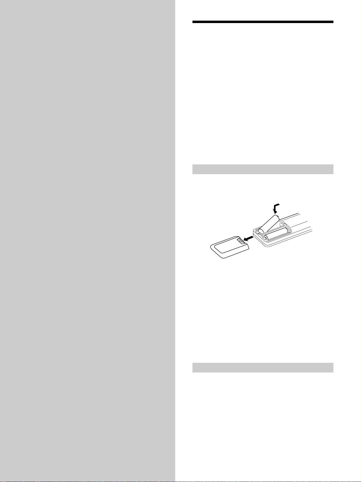
Inserting batteries into the remote
Insert R6 (size-AA) batteries with the + and – properly
oriented in the battery compartment. When using the
remote, point it at the remote sensor g on the amplifier.
]
}
}
]
z
When to replace batteries
Under normal conditions, the batteries should last for about 6
months. When the remote no longer operates the amplifier,
replace all batteries with new ones.
Notes
• Do not leave the remote in an extremely hot or humid place.
• Do not use a new battery with an old one.
• Do not expose the remote sensor to direct sunlight or lighting
apparatuses. Doing so may cause a malfunction.
• If you don’t use the remote for an extended period of time,
remove the batteries to avoid possible damage from battery
leakage and corrosion.
Before you get started
• Turn off the power to all components before making
any connections.
• Do not connect the AC power cords until all of the
connections are completed.
• Be sure to make connections firmly to avoid hum and
noise.
• When connecting an audio cord, be sure to match the
color-coded pins to the appropriate jacks on the
components: white (left, audio) to white; and red (right,
audio) to red.
4
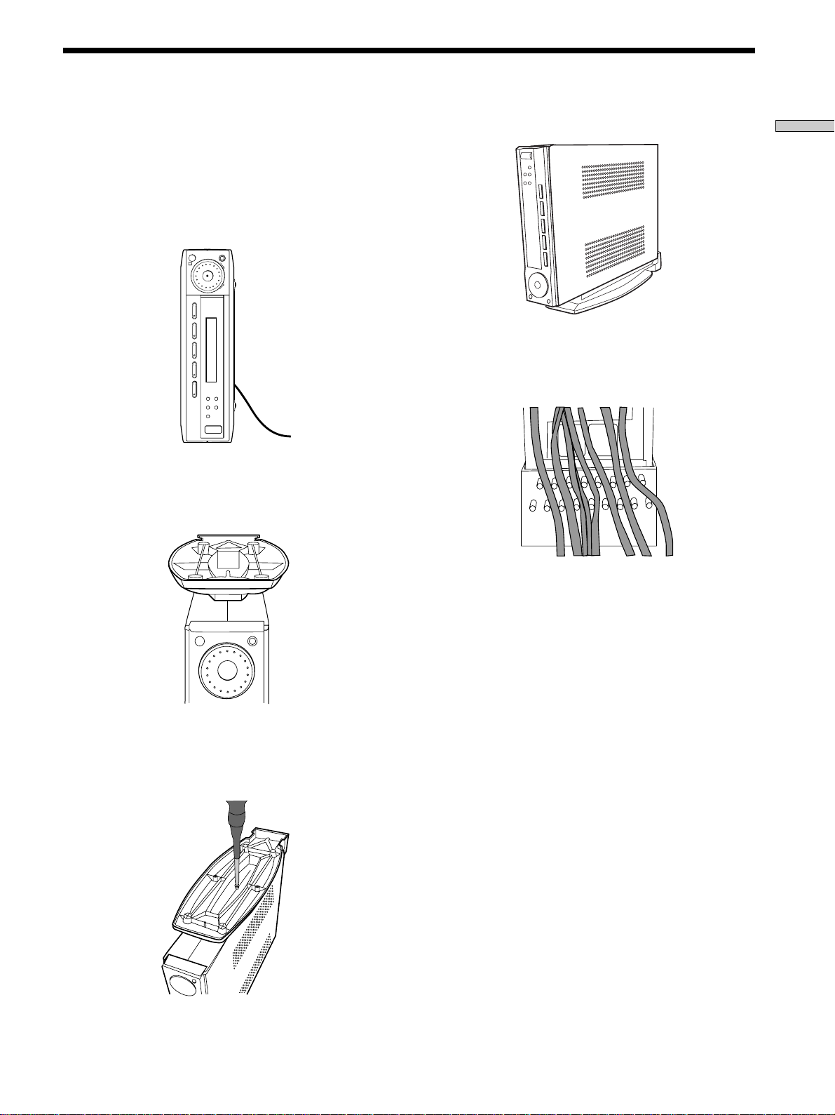
Setting Up the Amplifier
You can place the amplifier flat on a surface or on the
amplifier stand. Make sure that you do not place anything
on top of the amplifier.
1 Turn the amplifier to its side.
Be sure to place the amplifier with the ?/1 (power)
button at the bottom.
R
SOUND FIELD MODE
MASTER VOLUME
–+
VIDEO TV DVD AUX 5.1CH/SAT
+–
SURR LEVEL SET UP
?/1
2 Place the amplifier stand on top of the amplifier.
Be sure to align the hole on the stand to the hole on the
amplifier.
5 Place the amplifier stand on a flat surface.
Hooking Up the Components
Note
You can dress the power cord and other wires at the amplifier
stand as shown below.
3 Press to insert the stand to the amplifier.
4 Insert the screw and tighten it.
5
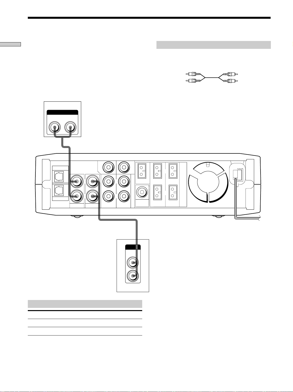
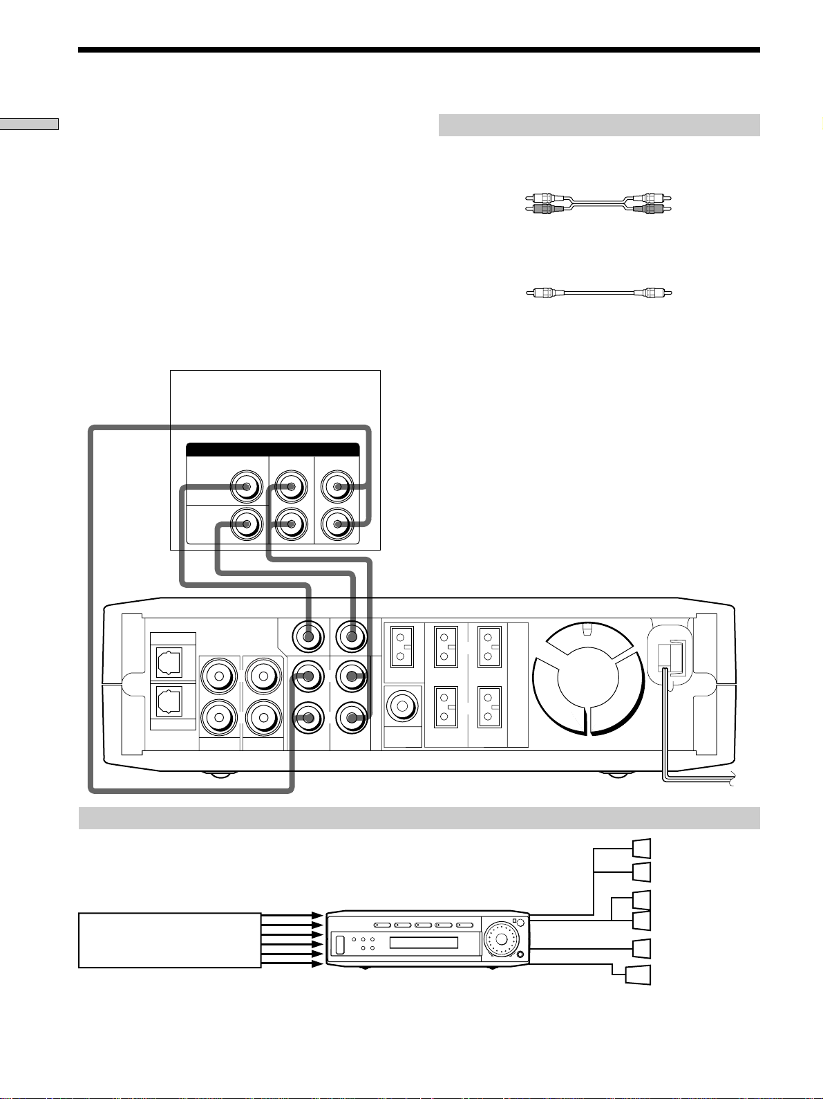
Video Component Hookups
Hooking Up the Components
TV
OUTPUT
AUDIO OUT
RL
DVD
Required cords
Audio cord (not supplied)
When connecting a cord, be sure to match the color -coded pins
to the appropriate jacks on the components.
White (L)
Red (R)
OUTPUT
AUDIO OUT
CENTER
L
L
WOOFER
CENTER
5.1CH/SAT
IMPEDANCE USE 8-16 Ω
L
SPEAKERS
White (L)
Red (R)
AUX
TV VIDEO FRONT
R
R
REAR
Jacks for connecting video components
Connect a To the
TV TV jacks
VCR VIDEO jacks
ç
OUTPUT
AUDIO
OUT
VCR
WOOFER
OUT
L
R
R
FRONT REAR
ç
IN OUT
INPUT OUTPUT
AUDIO
IN
L
R
AUDIO
OUT
6
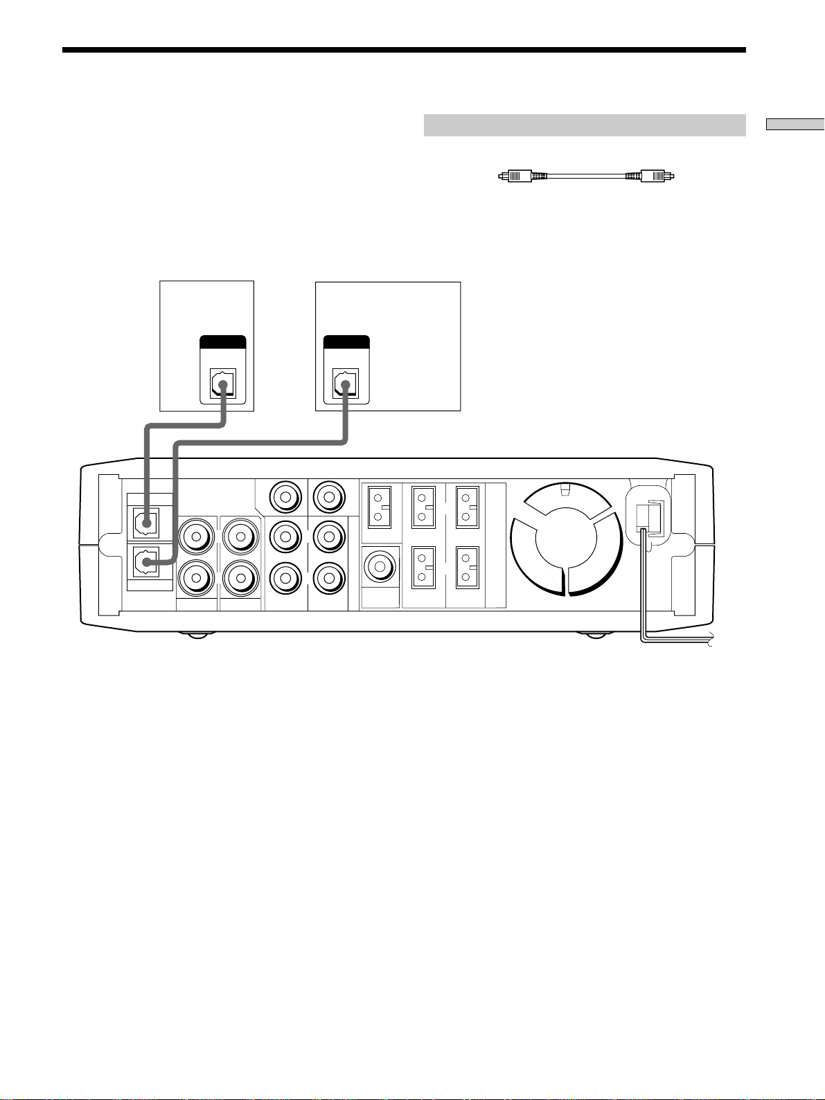
Digital Component Hookups
Connect the digital output jacks of your DVD player and
audio components (CD player, MD deck, etc.) to the
amplifier’s digital input jacks to bring the multi channel
surround sound of a movie theater into your home. To
enjoy full effect of multi channel surround sound, five
speakers (two front speakers, two rear speakers, and a
center speaker) and a sub woofer are required.
DVD player
DVD
(etc.)
OUTPUT
DIGITAL
OPTICAL
CENTER
L
CD player,
MD deck, etc.
OUTPUT
DIGITAL
OPTICAL
L
WOOFER
5.1CH/SAT
CENTER
Required cords
Optical digital cords (not supplied)
Black Black
Note
The optical digital input jacks on the amplifier are compatible
with sampling frequencies of 32 kHz, 44.1 kHz, 48 kHz and
96 kHz.
IMPEDANCE USE 8-16 Ω
L
SPEAKERS
Hooking Up the Components
AUX
TV VIDEO FRONT
R
R
WOOFER
REAR
Note
Connect the video jack of your DVD player to the VIDEO IN jack
of your TV.
OUT
R
FRONT REAR
7
5.1CH/SAT Hookups
Hooking Up the Components
Although this amplifier incorporates a multi channel
decoder, it is also equipped with 5.1CH/SAT jacks. These
connections allow you to enjoy multichannel software
encoded in formats other than Dolby Digital (AC-3) and
DTS. If your DVD player is equipped with 5.1CH
OUTPUT jacks, you can connect them directly to the
amplifier to enjoy the sound of the DVD player’s multi
channel decoder. Alternatively, the 5.1CH/SAT jacks can
be used to connect an external multi channel decoder.
To fully enjoy multi channel surround sound, you will
need five speakers (two front speakers, two rear speakers,
and a center speaker) and a subwoofer. Refer to the
instruction manual supplied with your DVD player, multi
channel decoder, etc., for details on the 5.1 channel input
hookups.
CENTER
DVD player,
Multichannel decoder, etc.
5.1CH OUTPUT
REAR
FRONT
Required cords
Audio cords (not supplied)
Two for the 5.1CH/SAT FRONT and REAR jacks
White (L) White (L)
Red (R) Red (R)
Monaural audio cords (not supplied)
Two for the 5.1CH/SAT CENTER and WOOFER jacks
Black Black
Note
When using the connections described below, adjust the level of
your surround speakers, center speaker and subwoofer from the
DVD player or multichannel decoder.
WOOFER
REAR
WOOFER
CENTER
5.1CH/SAT
WOOFER
OUT
L
R
FRONT REAR
DVD
AUX
TV VIDEO FRONT
CENTER
L
R
L
R
Example of a DVD player hookup using the 5.1 CH/SAT jacks
5.1 CH/SAT
VIDEO TV DVD AUX 5.1CH/SAT
?/1
DVD player
Note
See page 11 for details on speaker system hookup.
SURR LEVEL SET UP
+–
IMPEDANCE USE 8-16 Ω
SPEAKERS
SPEAKERS
FRONT
MASTER VOLUME
R
SPEAKERS
REAR/CENTER
–+
SUB WOOFER
SOUND FIELD MODE
Front Speaker (L)
Front Speaker (R)
Rear Speaker (L)
Rear Speaker (R)
Center Speaker
Active Woofer
8
Other Hookups
REAR
WOOFER
CENTER
5.1CH/SAT
WOOFER
DVD
AUX
TV VIDEO FRONT
CENTER
L
R
L
R
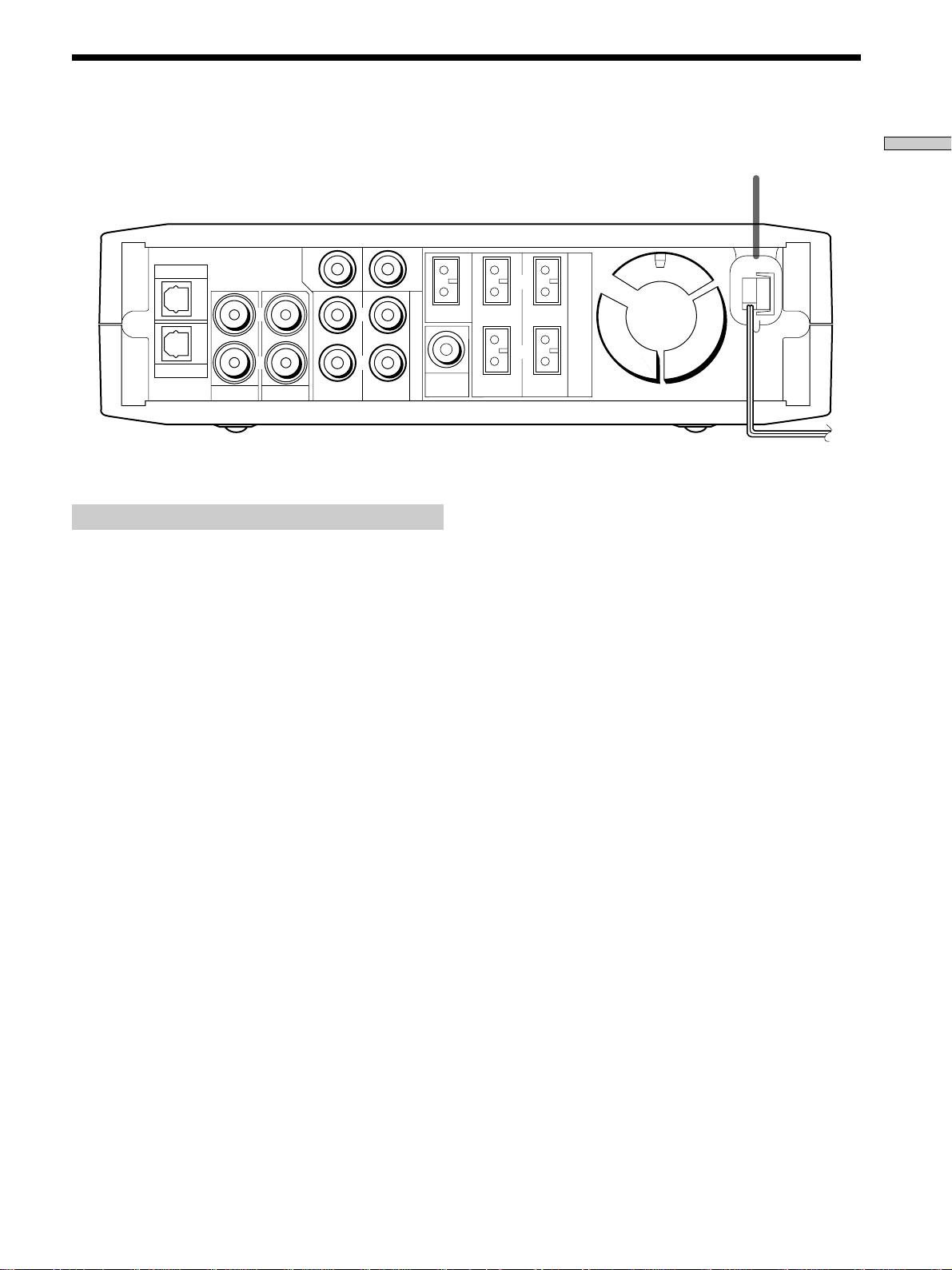
Connecting the AC power cord
Before connecting the AC power cord of this amplifier to a
wall outlet:
• Connect the speaker system to the amplifier (see page
11).
OUT
L
R
FRONT REAR
IMPEDANCE USE 8-16 Ω
SPEAKERS
AC power cord
To a wall outlet
Hooking Up the Components
b
Connect the AC power cord(s) of your video components
to a wall outlet.
Note
If the AC power cord is disconnected for about two weeks, the
amplifier’s entire memory will be cleared and the demonstration
will start.
9

Hooking Up
SET UP
R
?/1
VIDEO TV DVD AUX 5.1CH/SAT
SURR LEVEL SET UP
+–
SOUND FIELD MODE
MASTER VOLUME
–+
and Setting Up
the Speaker
System
This chapter describes how to hook
up your speaker system to the
amplifier, how to position each
speaker, and how to set up your
speakers to enjoy multi channel
surround sound.
+/– buttons
Brief descriptions of buttons and control
used to set up the speaker system
SET UP button: Press to enter the setup mode when
specifying speaker types and distances.
+/– buttons: Use to select parameters after pressing the
SET UP button.
10
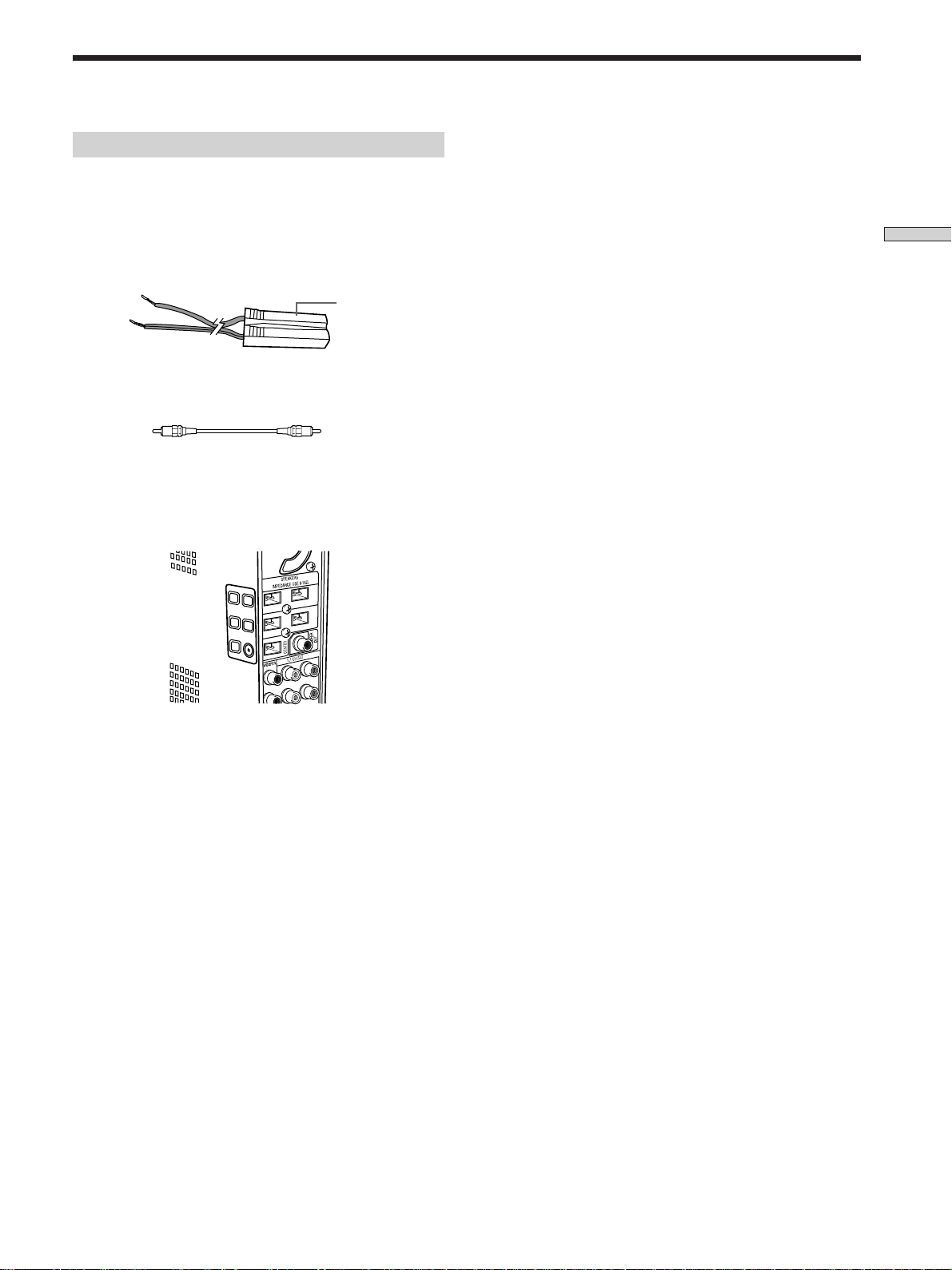
Speaker System Hookup
Required cords
Speaker connecting cords (supplied)
One white for SPEAKERS FRONT LEFT
One red for SPEAKERS FRONT RIGHT
One green for SPEAKERS CENTER
One blue for SPEAKERS REAR LEFT
One yellow for SPEAKERS REAR RIGHT
Hooking Up and Setting Up the Speaker System
(–)
(+)
Monaural connecting cord (supplied)
One for an active sub woofer
Black Black
Speaker plug
Notes
• Make sure that you insert the speaker connecting cords
according to the colour as labelled on the top of the amplifier of
the speaker plug ends.
• The polarity of the speaker plugs is fixed on the amplifier.
11
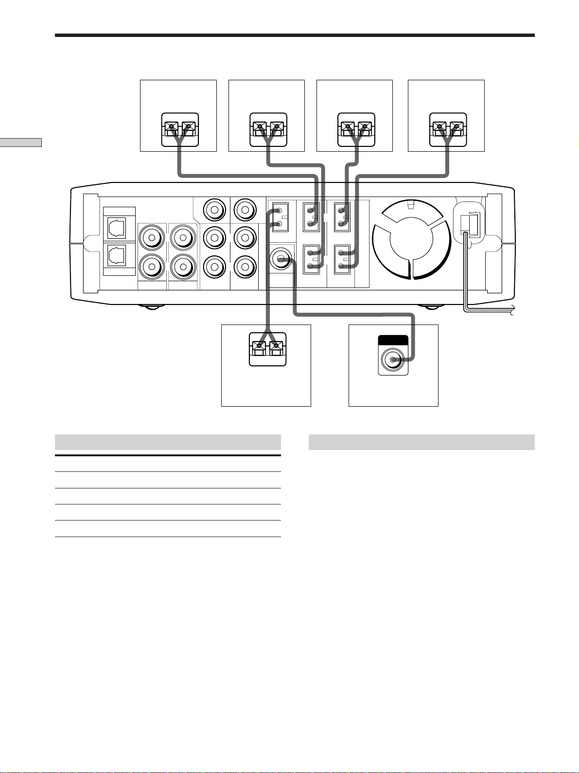
Speaker System Hookup
Front speaker (L)
}
]
Hooking Up and Setting Up the Speaker System
CENTER
DVD
L
R
AUX
TV VIDEO FRONT
L
R
Front speaker (R)
}
WOOFER
CENTER
5.1CH/SAT
WOOFER
REAR
OUT
}
Rear speaker (L)
]
FRONT REAR
}
L
R
]
IMPEDANCE USE 8-16 Ω
SPEAKERS
]
INPUT
Rear speaker (R)
}
]
Center speaker
Terminals for connecting the speakers
Connect the To the
Front speakers (8 ohm) SPEAKERS FRONT terminals
Rear speakers (8 ohm) SPEAKERS REAR terminals
Center speaker (8 ohm) SPEAKERS CENTER terminals
Active sub woofer WOOFER OUT jack
Active sub woofer
Notes on speaker system hookup
• Make sure the plus (+) and the minus (–) terminals on
the speakers are matched to the corresponding plus (+)
and minus (–) terminals on the speaker plugs.
• Make sure all connections are firm. Contact between
bare speaker wires at the speaker terminals may cause a
short-circuit.
Tip
All striped wires are plus (+) in polarity, and should be connected
to the plus (+) speaker terminals.
12
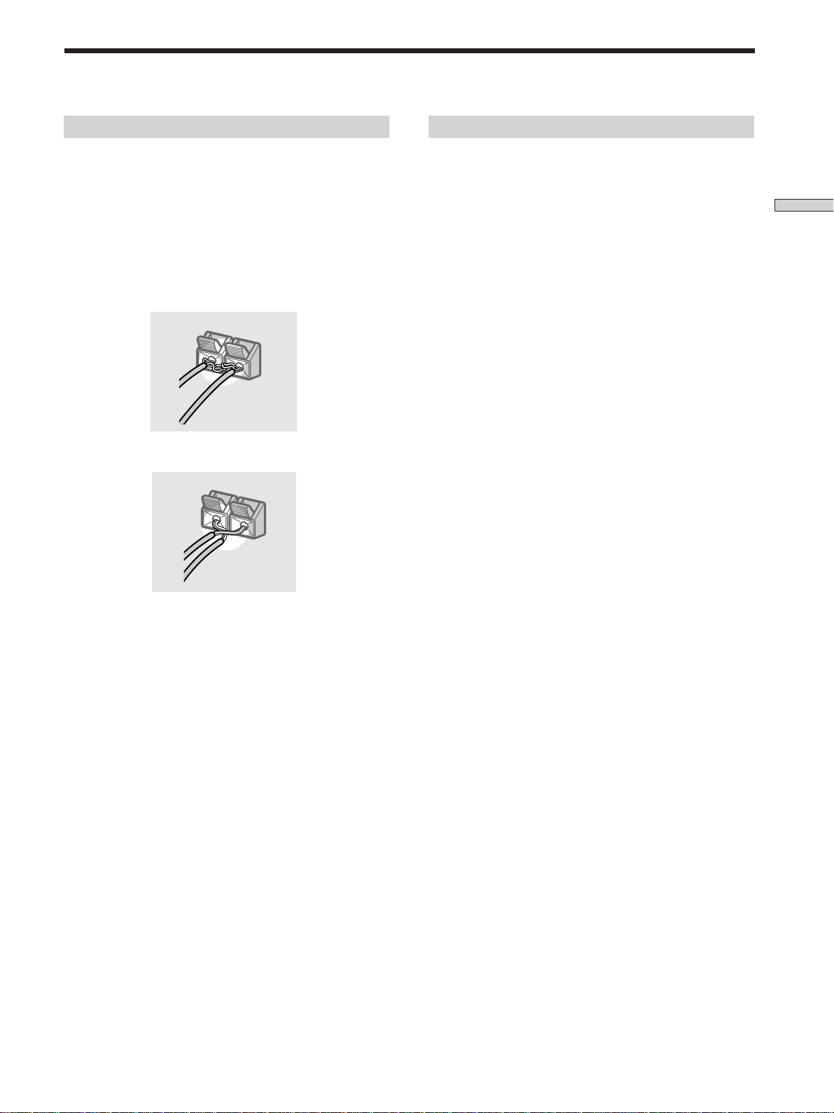
To avoid short-circuiting the speakers
Short-circuiting of the speakers may damage the
amplifier. To prevent this, make sure to take the following
precautions when connecting the speakers.
To avoid damaging your speakers
Make sure that you turn down the volume before you
turn off the amplifier. When you turn on the amplifier, the
volume remains at the level you turn off the amplifier.
Make sure the stripped ends of each speaker cord
does not touch another speaker terminal or the
stripped end of another speaker cord.
Examples of poor conditions of the speaker cord
Stripped speaker cord is touching another speaker terminal.
Stripped cords are touching each other due to excessive
removal of insulation.
Hooking Up and Setting Up the Speaker System
After connecting all the components, speakers,
and AC power cord, output a test tone to check
that all the speakers are connected correctly. For
details on outputting a test tone, see page 18.
If no sound is heard from a speaker while outputting a
test tone or a test tone is output from a speaker other than
the one whose name is currently displayed on the
amplifier, the speaker may be short-circuited. If this
happens, check the speaker connection again.
13
 Loading...