

Page 1
Home Theater
System
4-230-316-12(1)
Operating instructions
Mode d’emploi
Gebruiksaanwijzing
Bruksanvisning
GB
FR
NL
SE
HT-K170
© 2000 Sony Corporation
GB
1
Page 2

Getting Started
WARNING
To prevent fire or shock
hazard, do not expose
the unit to rain or
moisture.
To avoid electrical shock, do not open
the cabinet. Refer servicing to qualified
personnel only.
Precautions
On safety
• Should any solid object or liquid fall
into the cabinet, unplug the amplifier
and have it checked by qualified
personnel before operating it any
further.
On power sources
• Before operating the amplifier, check
that the operating voltage is identical
with your local power supply. The
operating voltage is indicated on the
nameplate at the rear of the amplifier.
• The amplifier is not disconnected
from the AC power source (mains) as
long as it is connected to the wall
outlet, even if the amplifier itself has
been turned off.
• If you are not going to use the
amplifier for a long time, be sure to
disconnect the amplifier from the
wall outlet. To disconnect the mains
lead, grasp the plug itself; never pull
the cord.
• The AC power cord (mains lead)
must be changed, at a qualified
service shop only.
• The mains switch is located on the
front exterior.
On placement
• Do not install the appliance in a
confined space, such as a bookcase or
built in cabinet.
• Place the amplifier in a location with
adequate ventilation to prevent heat
buildup and prolong the life of the
amplifier.
• Do not place the amplifier near heat
sources, or in a place subject to direct
sunlight, excessive dust or
mechanical shock.
• Do not place anything on top of the
cabinet that might block the
ventilation holes and cause
malfunctions.
• Do not set the speakers in an inclined
position.
• Do not place the speakers in locations
that are:
– Extremely hot or cold
– Dusty or dirty
– Very humid
– Subject to vibrations
– Subject to direct sunlight
On operation
• Before connecting other components,
be sure to turn off and unplug the
amplifier.
• Do not drive the speaker system with
a continuous wattage exceeding the
maximum input power of the system.
• If the polarity of the speaker
connections are not correct, the bass
tones will be weak and the position of
the various instruments obscure.
• Contact between bare speaker wires
at the speaker terminals may result in
a short-circuit.
• The speaker grille cannot be removed.
Do not attempt to remove the grille
on the speaker system. If you try to
remove it, you may damage the
speaker.
If you encounter color irregularity on
a nearby TV screen
This speaker system is magnetically
shielded to allow it to be installed near a
TV set. However, color irregularities
may still be observed on certain types of
TV sets.
If color irregularity is observed…
p Turn off the TV set once, then turn
it on again after 15 to 30 minutes.
If color irregularity is observed
again…
p Place the speakers further away
from the TV set.
If howling occurs
Reposition the speakers or turn down
the volume on the amplifier.
On cleaning
• Clean the cabinet, panel and controls
with a soft cloth slightly moistened
with a mild detergent solution. Do
not use any type of abrasive pad,
scouring powder or solvent such as
alcohol or benzine.
If you have any question or problem
concerning your amplifier, please
consult your nearest Sony dealer.
GB
2
Page 3
Getting Started
About This Manual
Conventions
• The instructions in this manual
describe the controls on the amplifier
and speakers. You can also use the
controls on the remote if they have
the same or similar names as those on
the amplifier.
• The following icons are used in this
manual:
Indicates that you can use only
the remote to do the task.
Indicates hints and tips for
making the task easier.
This amplifier contains a Dolby Pro
Logic Surround decoder.
Manufactured under license from Dolby
Laboratories.
“Dolby”, “AC-3”, “Pro Logic” and the
double-D symbol ; are trademarks of
Dolby Laboratories.
Hold down ?/1 and press CENTER
MODE to change the fan control
setup. Each time you do the
procedure above, the following setup
appears.
Select To
FAN ON Turn on the fan at all
times.
FAN AUTO Turn on the fan
automatically when
there is sufficient
speaker output.
TABLE OF CONTENTS
Getting Started
Unpacking 4
Hookup Overview 4
Video Component Hookups 5
Speaker System Hookups and Setups 6
AC Hookups 9
Before You Use Your Amplifier 10
Amplifier Operations
Selecting a Component 11
Changing the Factory Setting of a FUNCTION Button 13
Using the Sleep Timer 14
Using Surround Sound
Choosing a Sound Field 15
Getting the Most Out of Dolby Pro Logic Surround Sound 16
Additional Information
Troubleshooting 18
Specifications 19
Glossary 20
Remote Button Description 21
Index 22
Rear Panel Descriptions 22
GB
3
Page 4
Getting Started
Getting Started
Unpacking
Check that you received the following items with your
amplifier:
• Remote commander (remote) (1)
• Size AA (R6) batteries (2)
• Scart adaptor (1)
• Speakers (5)
• Front speakers (2)
• Rear speakers (2)
• Center speaker (1)
• Subwoofer (1)
• Speaker connecting cord, 10 m (2)
• Speaker connecting cord, 2.5 m (3)
• Monaural connecting cord (1 phono to 1 phono) (1)
• Foot pads (20)
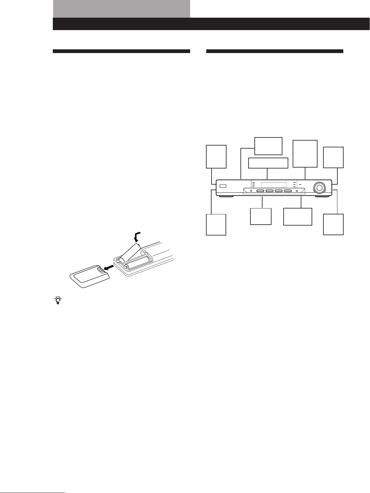
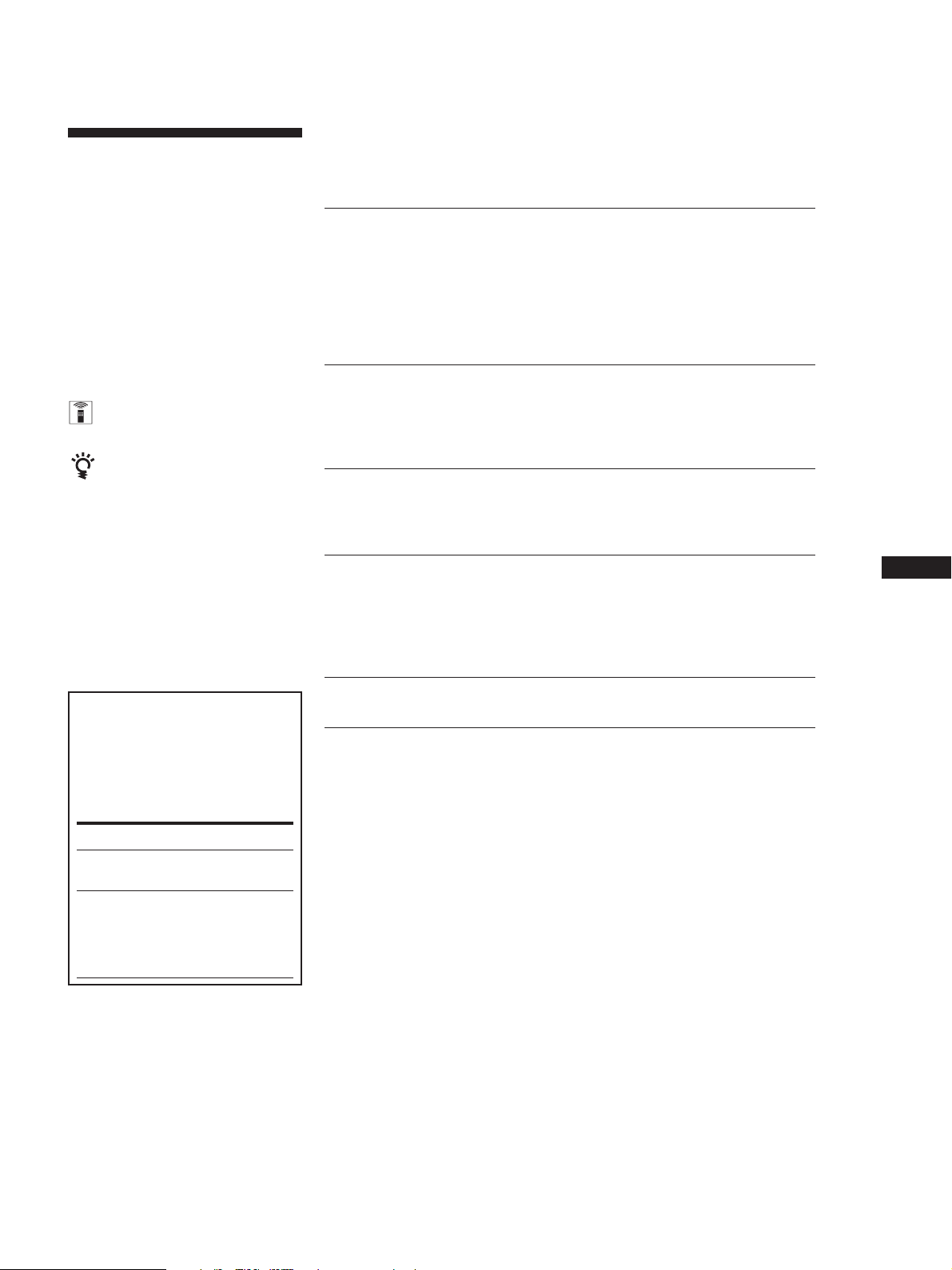
Inserting batteries into the remote
Insert two size AA (R6) batteries with the + and – on
the battery compartment. When using the remote,
point it at the remote sensor g on the amplifier.
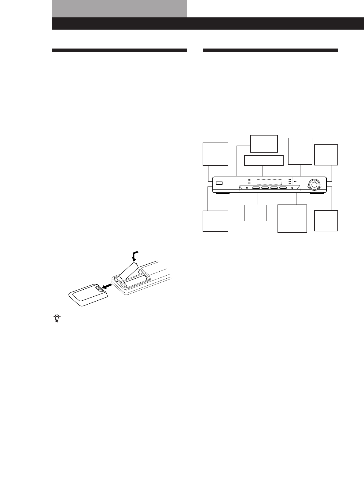
Hookup Overview
The amplifier allows you to connect and control the
following video components. Follow the hookup
procedures for the components that you want to
connect to the amplifier on the pages specified. To
learn the locations and names of each jack, see “Rear
Panel Descriptions” on page 22.
Video Component
Speaker System
Hookups (6)
Front
speaker
(L)
Rear
speaker
(L)
Hookups (5)
TV
VCR
Center
speaker
DVD
player/
AC-3
decoder
Active
subwoofer
Front
speaker
(R)
Rear
speaker
(R)
]
}
}
]
When to replace batteries
Under normal use, the batteries should last for about 6
months. When the remote no longer operates the
amplifier, replace both batteries with new ones.
Notes
• Do not leave the remote in an extremely hot or humid
place.
• Do not use a new battery with an old one.
• Do not expose the remote sensor to direct sunlight or
lighting apparatuses. Doing so may cause a malfunction.
• If you don’t use the remote for an extended period of time,
remove the batteries to avoid possible damage from
battery leakage and corrosion.
Before you get started
• Turn off the power to all components before making
any connections.
• Do not connect the mains lead until all of the
connections are completed.
• Be sure to make connections firmly to avoid hum
and noise.
• When connecting an audio cable, be sure to match
the colour-coded pins to the appropriate jacks on the
components: White (left, audio) to White; and Red
(right, audio) to Red.
GB
4
Page 5

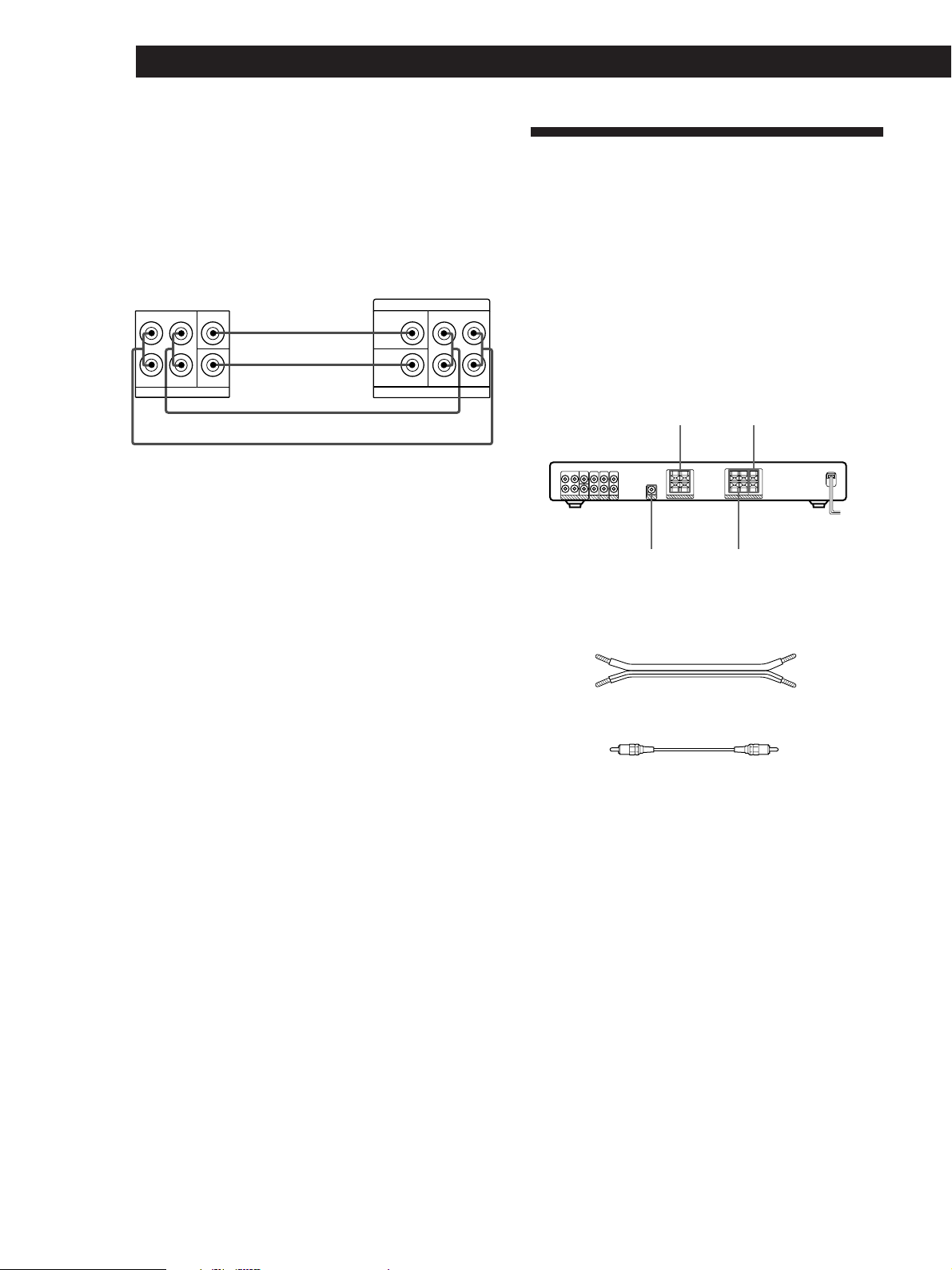
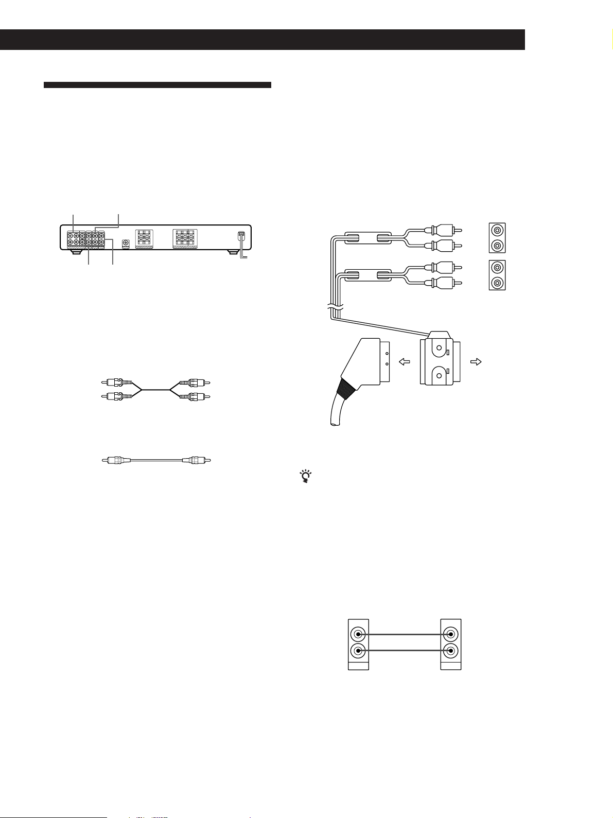
Video Component Hookups
Getting Started
Hookups
The arrow l indicates signal flow.
Overview
This section describes how to connect video
components to the amplifier. For specific locations of
the jacks, see the illustration below.
5.1CH/DVD TV
DVD 2CH
What cords will I need?
• Scart adaptor (supplied)
• Euro AV cable (not supplied) (1 for each TV or VCR)
• Audio cords (not supplied) (1 for DVD player, 2 for AC-3
decoder’s FRONT and REAR jacks)
Red (R)
• Monaural audio cords (not supplied)
(2 for AC-3 decoder’s CENTER and WOOFER jacks)
VIDEO
White (L)White (L)
Red (R)
BlackBlack
TV/VCR
You can listen to the sound from VCR or TV by
connecting the audio signal from VCR or TV to the
amplifier.
Amplifier
VIDEO AUDIO IN
To VTR audio input
To TV audio input
Euro AV cable (not
supplied)
n
To TV
ç
ç
Scart adaptor
(supplied)
White
(L)
Red
(R)
White
(L)
Red
(R)
TV
VTRTV
L
R
L
R
If you have another component, such as a second VCR
or LD player, connect it to the DVD 2CH jacks.
DVD Player
If your DVD player does not have 5.1 CH output,
connect the audio output jacks of the DVD player to the
DVD 2CH jacks of the amplifier.
Amplifier
DVD 2CH
AUDIO IN
LL
DVD 2CH
L
DVD player
AUDIO OUT
AUDIO OUT
RR
(continued)
GB
5
Page 6
Getting Started
DVD player with AC-3 decoder
If you have a Dolby Digital (AC-3) decoder or a DVD
player with a built-in AC-3 decoder, you can play
decoded Dolby Digital (AC-3) soundtracks through the
speakers connected to the amplifier. Connect the
decoder as follows:
Amplifier
5.1 CH/DVD
FRONT
L L
L
CENTER
REAR
L
WOOFER
5.1CH / DVD
L
L
Dolby Digital AC-3
decoder (etc.)
PRE OUT
REAR
CENTER
WOOFER
5.1CH OUTPUT
FRONT
Speaker System Hookups and
Setups
Overview
This section describes how to connect the supplied
speakers (SS-MS215) to the amplifier. Connecting the
active woofer (SA-WMS215) will increase bass
response.
For specific locations of the terminals, see the
RR
illustration below.
FRONT
SPEAKERS
CENTER
SPEAKER
WOOFER
(AUDIO OUT)
REAR
SPEAKERS
What cords will I need?
• Speaker connecting cord (supplied) (1 for each speaker)
(+)(+)
(–)
• Monaural connecting cord (supplied)
Black
(–)
Black
GB
6
Page 7
Getting Started
R
EAR
+
–
RL
RL
REAR
+
–
R
L
RL
Hookups
Front speakers (SS-MS215)
Front speaker
(R)
Amplifier
R-FRONT-L
SPEAKERS
Rear and center speakers (SS-MS215)
Rear speaker
(R)
Amplifier
R-REAR-L CENTER
SPEAKERS
Center speaker
Notes
• Be sure to match the speaker cord to the appropriate
terminal on the components: + to + and – to –. If the cords
are reversed, the sound will be distorted and will lack
bass.
• Make sure all connections are firm. Contact between bare
speaker wires at the speaker terminals may cause a shortcircuit.
Front speaker
(L)
Rear speaker
(L)
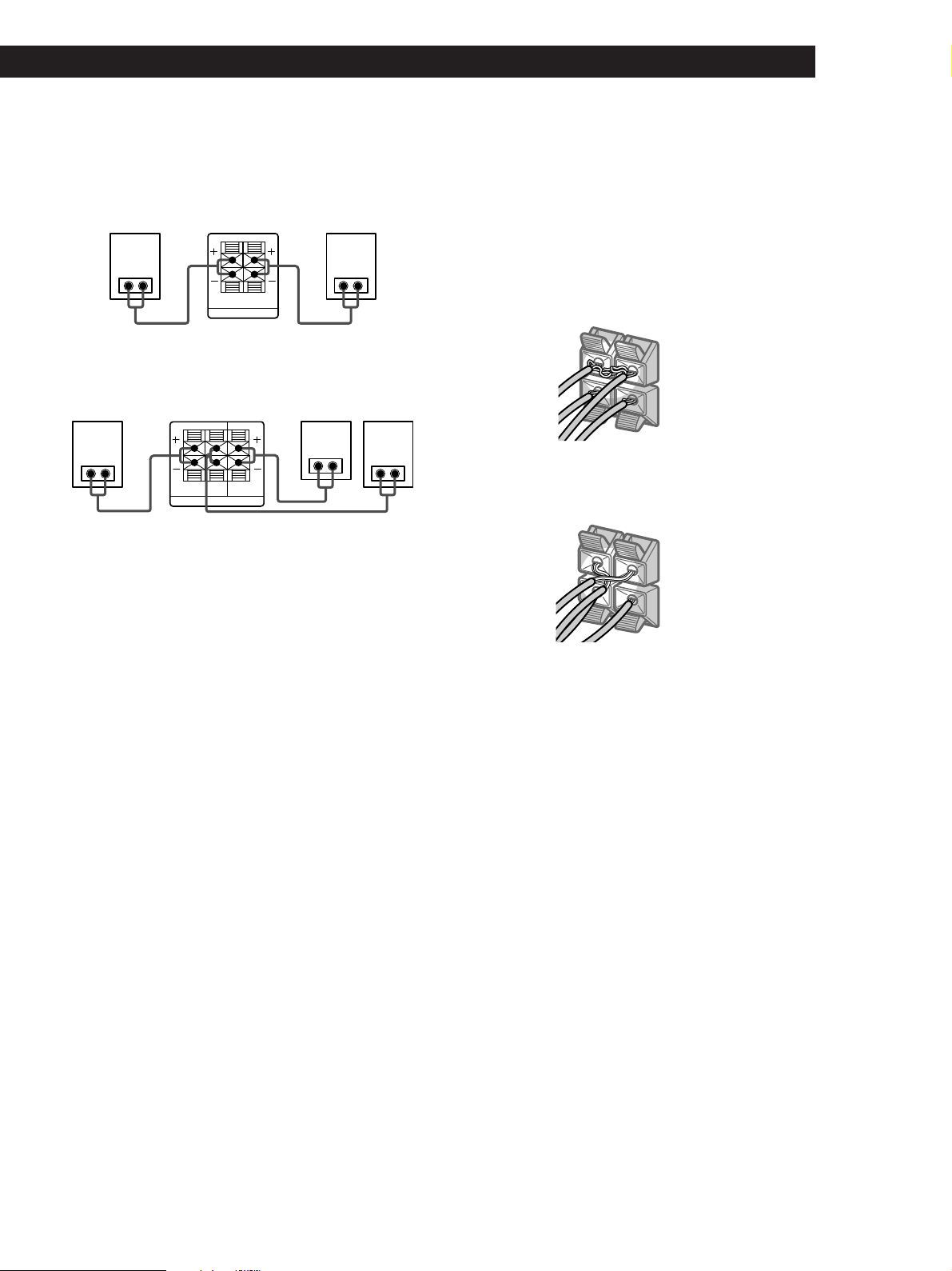
To avoid short-circuiting the speakers
Short-circuiting of the speakers may damage the
amplifier. To prevent this, make sure to take the
following precautions when connecting the speakers.
Make sure the stripped ends of each speaker cord does
not touch another speaker terminal or the stripped end
of another speaker cord.
Examples of poor conditions of the speaker cord:
Stripped speaker cord is touching another speaker
terminal.
Stripped cords are touching each other due to excessive
removal of insulation.
After connecting all the components, speakers, and AC
power cord, output a test tone to check that all the
speakers are connected correctly. For details on
outputting a test tone, refer to “Adjusting the speaker
volume” on page 17.
If you have connected rear speakers, be sure to press
the 5.1 CH/DVD button on the amplifier before
outputting a test tone so that the tone is output
individually from the left and right rear speakers.
If no sound is heard from a speaker while outputting a
test tone or a test tone is output from a speaker other
than the one whose name is currently displayed on the
amplifier, the speaker may be short-circuited. If this
happens, check the speaker connection again.
GB
7
Page 8
Getting Started
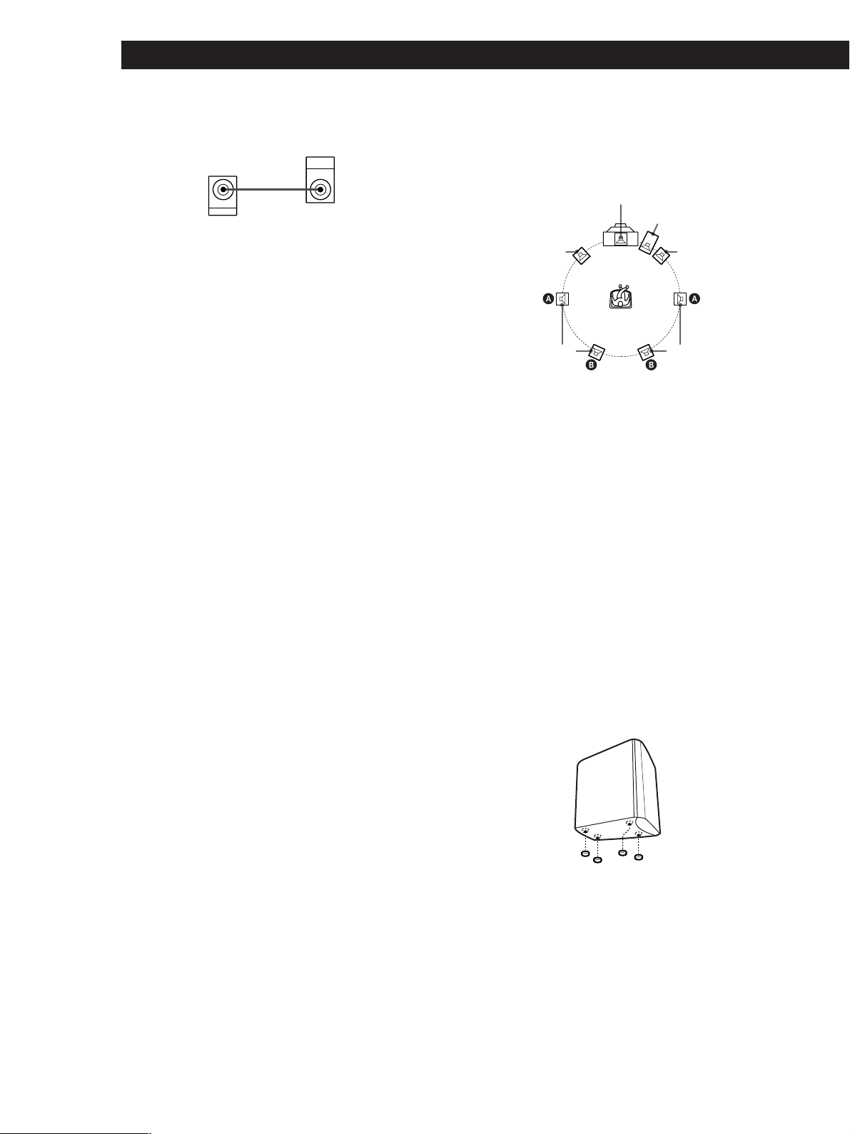
Active subwoofer (SA-WMS215)
Active subwoofer
Amplifier
AUDIO OUT
WOOFER
INPUT
Caution
• The speaker unit of the active subwoofer is located at the
bottom of the active subwoofer.
• Avoid contact with the speaker unit as it is without a
cover.
• Place the active subwoofer on a flat surface to ensure there
is no obstruction to the speaker unit.
Positioning the speakers
Location of each speaker
Center
Subwoofer
Front
(Left)
Rear
(Left)
Each speaker should face the listening position. Better
surround effect will result if all speakers are set at the
same distance from the listening position.
Place the front speakers at a suitable distance to the left
and right of the television.
Place the subwoofer on either side of the television.
Place the center speaker on the top-center of the TV set.
The placement of rear speakers greatly depends on the
configuration of the room. The rear speakers may be
placed on both sides of the listening position A or
behind the listening position B.
Front
(Right)
Rear
(Right)
Setting the speakers
To prevent speaker vibration or movement while
listening, attach the supplied foot pads to the bottom
four corners of the center speaker, front speakers, and
rear speakers.
Front/Center/Rear
speakers
Foot pads
GB
8
Page 9
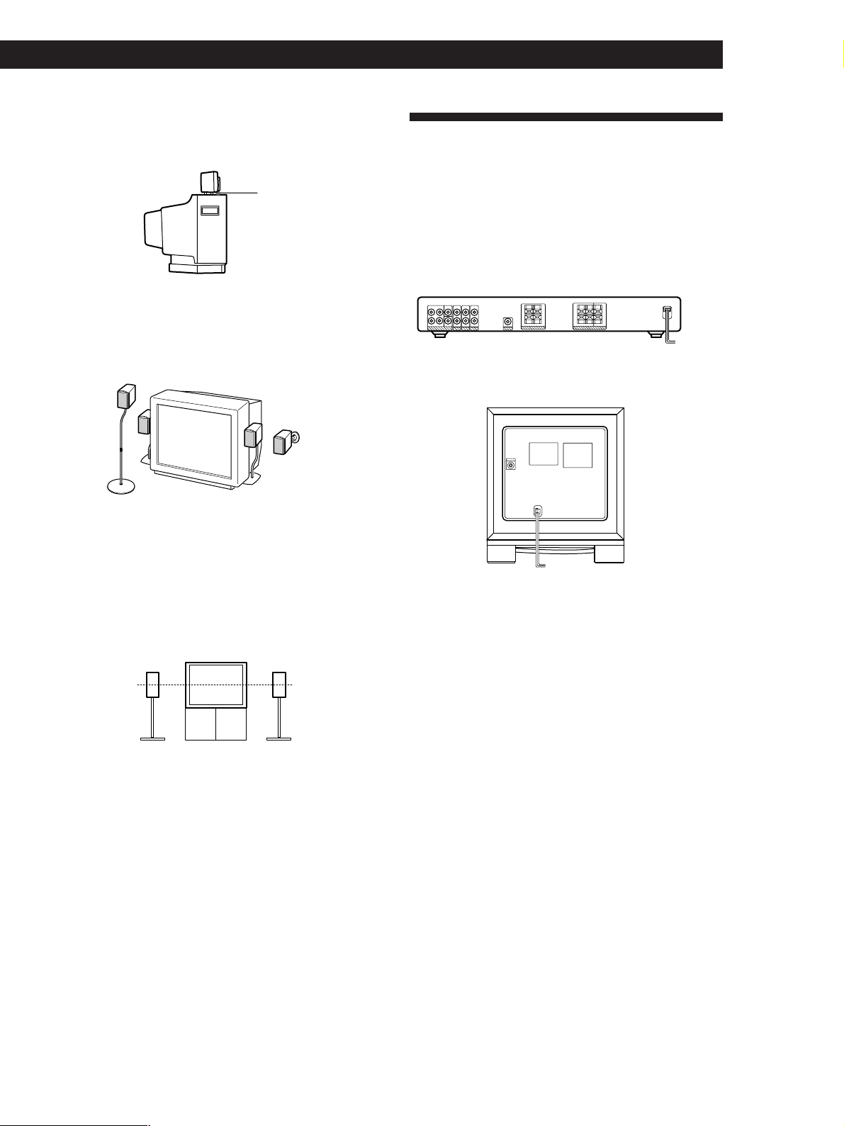
Setting the center speaker
Set the center speaker firmly on top of the TV set,
making sure it is completely level.
Getting Started
AC Hookups
Foot pads
Setting other speakers
For greater flexibility in the positioning of the speakers,
use the optional WS-FV10, WS-TV10, or WS-WV10
speaker stand (available only in certain countries).
WS-FV10 WS-TV10
Note
You do not need to attach the foot pads if you are using the
speaker stand.
WS-WV10
(for rear speakers)
Connecting the mains lead
Connect the mains lead from this amplifier, active
subwoofer and from your video components to a wall
outlet.
Amplifier
/
to a wall outlet
Active subwoofer
/
to a wall outlet
Tip
The height of the front speakers should be adjusted to about
the center of the TV screen.
GB
9
Page 10
Getting Started
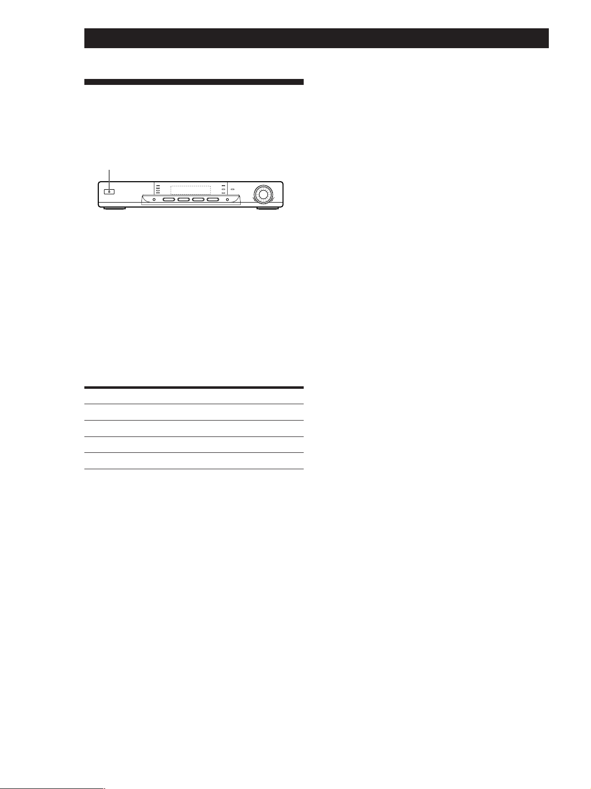
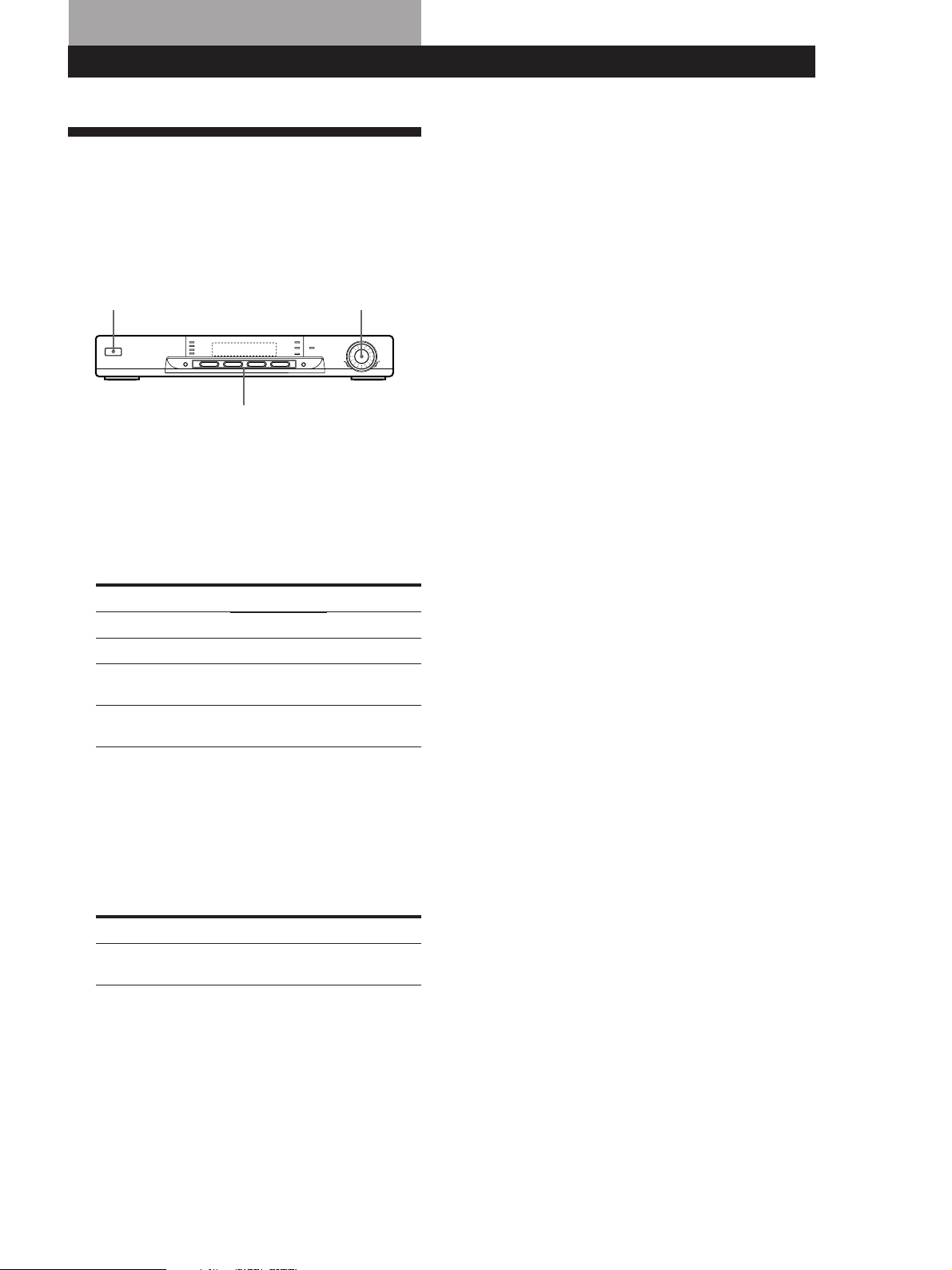
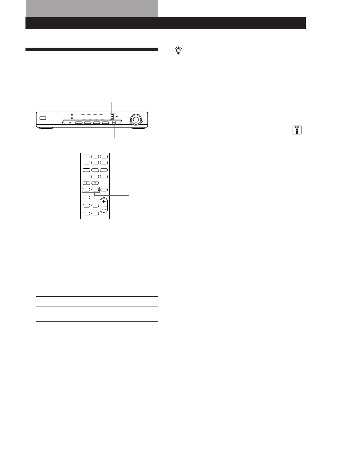
Before You Use Your Amplifier
Before you use your amplifier for the first time or when
you want to clear the amplifier’s memory, do the
procedure below:
?/1 (power)
1 Turn off the amplifier.
2 Press ?/1 (power) for more than 4 seconds.
“INITIAL” appears in the display and the items
including the following are reset or cleared:
• All sound field parameters are reset to their
factory settings.
• The fan control setup is reset to FAN ON.
Note
If you are using a Sony DVD player together with this home
theater system, set your DVD player to the following
configuration:
Speakers
Front
Center
Rear
Subwoofer
If you are using a non Sony DVD player, refer to the
operating instructions supplied with the DVD player for
speaker setup.
Settings
SMALL
SMALL
SMALL
YES
10
GB
Page 11
Amplifier Operations
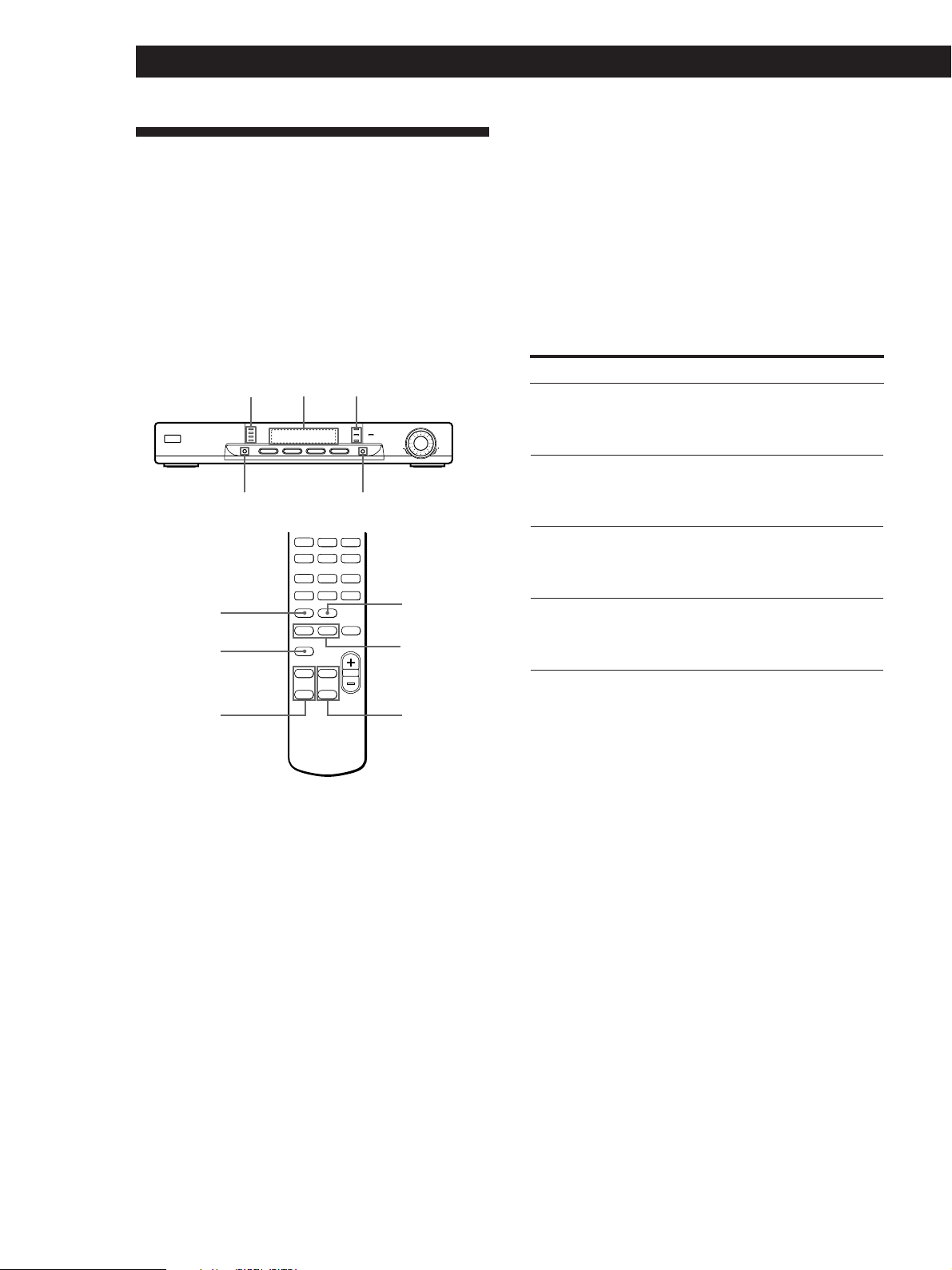
Selecting a Component
To listen to a connected component, first select the
function on the amplifier or with the remote.
Before you begin, make sure you have:
• Connected all components securely and correctly as
indicated on pages 5 to 9.
1/u (power)
MASTER VOLUME
Amplifier Operations
Watching video programmes
To take full advantage of the amplifier’s surround
sound effects, like Dolby Surround, turn off the
speakers on your TV before you start. This also lets you
use the amplifier’s remote to control the sound.
To watch TV programmes, do the following:
1 Turn on your TV.
2 Turn on the amplifier and press TV.
To watch videos or DVDs, do as follows:
Function buttons
1 Press 1/u (power) to turn on the amplifier.
2 Turn MASTER VOLUME to VOL MIN (indicated
on the display) to avoid damaging your speakers.
3 Press a function button to select the component
you want to use:
To watch
Video tapes
TV programmes
Digital versatile disc
(DVD)
DVD through
AC-3 decoder
To operate with the remote
Refer to “Using the remote” on page 12 for details.
Press
VIDEO
TV
DVD 2CH
5.1 CH/DVD
TV input mode
VIDEO
VIDEO
VIDEO
VIDEO
4 Turn on the component, the VCR for example,
and start playback.
1 Turn on your TV and set the TV’s input to match
the video component you watch.
2 Turn on the amplifier and press the function
button (VIDEO, DVD 2CH or 5.1 CH/DVD) to
select the component you want to use.
3 Turn on the video component and start
playback.
5 Turn MASTER VOLUME to adjust the volume.
To
Mute the sound
Do this
Press MUTING on the remote.
Press again to restore the sound.
(continued)
11
GB
Page 12
Amplifier Operations
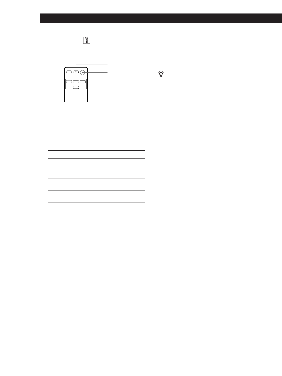
Using the remote
The remote lets you operate the amplifier and the Sony
components that are connected to it.
AV ?/1
?/1
SYSTEM
CONTROL/
FUNCTION
1 Press one of the SYSTEM CONTROL/
FUNCTION buttons to select the component you
want to use.
The amplifier and the selected component turn
on.
The SYSTEM CONTROL/FUNCTION buttons on
the remote are factory-set as follows:
To play
TV programmes
VHS Tapes
(VTR-3 mode)
DVD player
(for 2-ch playback)
DVD player/
AC-3 decoder
Press
TV
VIDEO
DVD
5.1 CH
To turn off the components
Press AV ?/1 and ?/1 simultaneously. This will also turn
off the Sony video/audio components at the same time. If
the components do not turn off, press the power switch on
the components.
If you use a Sony TV
• The TV turns on automatically and switches to the
appropriate video input when you press VIDEO. If
the TV does not switch to the appropriate input
automatically, press TV/VIDEO on the remote.
• When you use the TV only, turn on the TV using the
TV’s remote.
If you want to change the factory setting of a button
See “Changing the Factory Setting of a FUNCTION
Button” on page 13.
If the component does not turn on
Press the power switch on the component.
2 Start playing.
Refer to “Remote Button Descriptions” on page 21
for details.
12
GB
Page 13
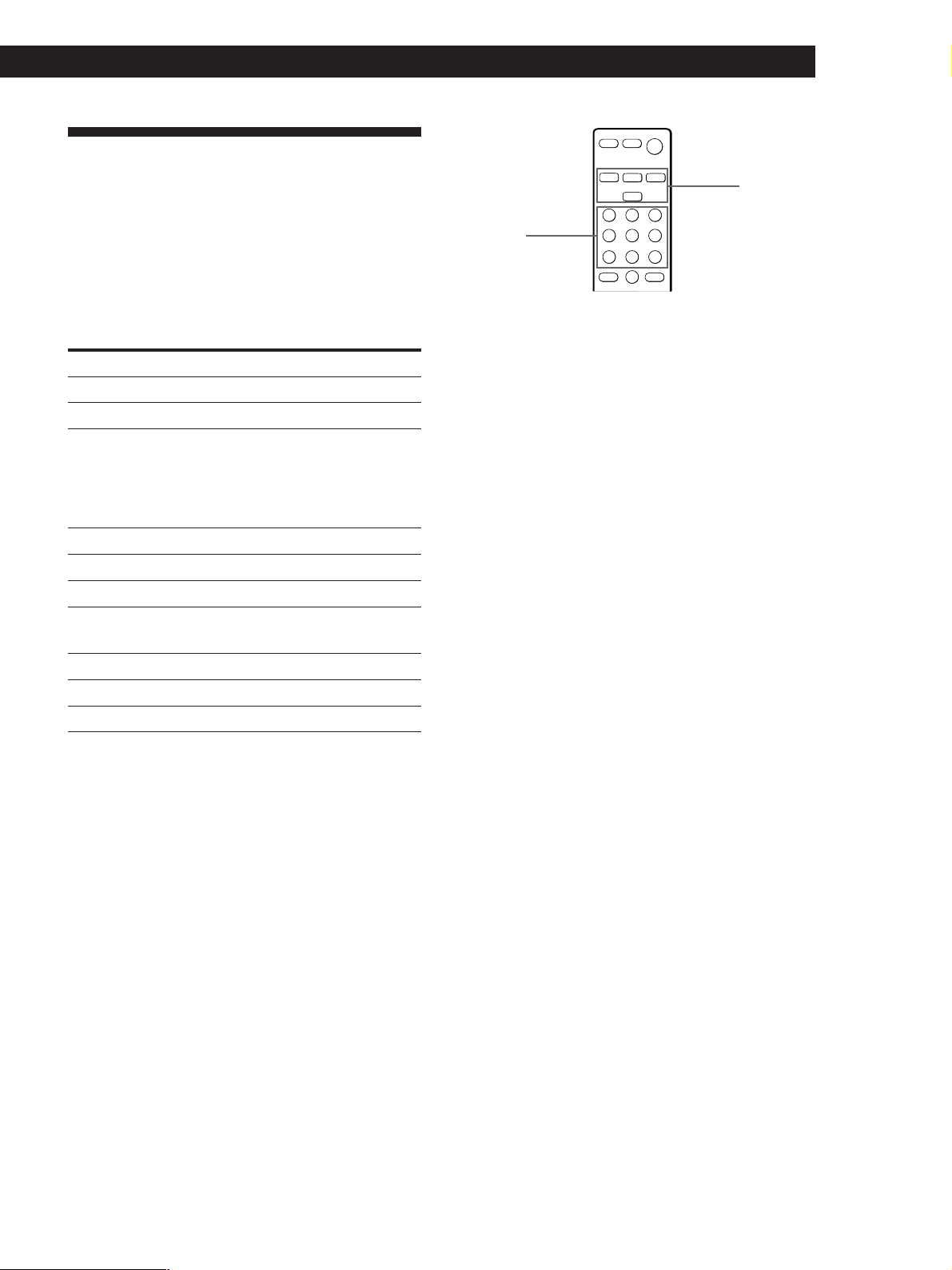
Changing the Factory Setting
Amplifier Operations
of a FUNCTION Button
If the factory settings of the SYSTEM CONTROL/
FUNCTION buttons (“Using the remote” on page 12)
don’t match your system components, you can change
them. The following table shows the possibility of
alternate function assignment for each button.
Button Possible assignment
VIDEO VTR 1, VTR 2, VTR 3
DVD DVD, LDP, CD
* Initial setting of VIDEO is VTR 3.
* Sony VCRs are operated with a VTR 1, 2, or 3 setting that
corresponds to Beta, 8mm, and VHS, respectively.
Resetting key table for function key VIDEO
VTR 1 CURSOR UP
VTR 2 ENTER/EXECUTE
VTR 3 CURSOR DOWN
Resetting key table for function key DVD
DVD EXIT/RETURN
LD DISPLAY
CD CURSOR RIGHT
SYSTEM
CONTROL/
FUNCTION
MENU
control keys
For example, if you connect a Sony LD player to the
DVD jacks, you can assign the DVD button to set the
remote to control the LD player.
1 Hold down the SYSTEM CONTROL/FUNCTION
button whose function you want to change (DVD,
for example).
2 Press the corresponding button of the component
you want to assign to the SYSTEM CONTROL/
FUNCTION button (DISPLAY, LD player, for
example).
Now you can use the DVD button to control your
Sony LD player.
To reset a button to its factory setting
Repeat the above procedure.
To reset all the function buttons to their factory setting
Press ?/1, AV ?/1 and MASTER VOL – at the same time.
13
GB
Page 14
Amplifier Operations
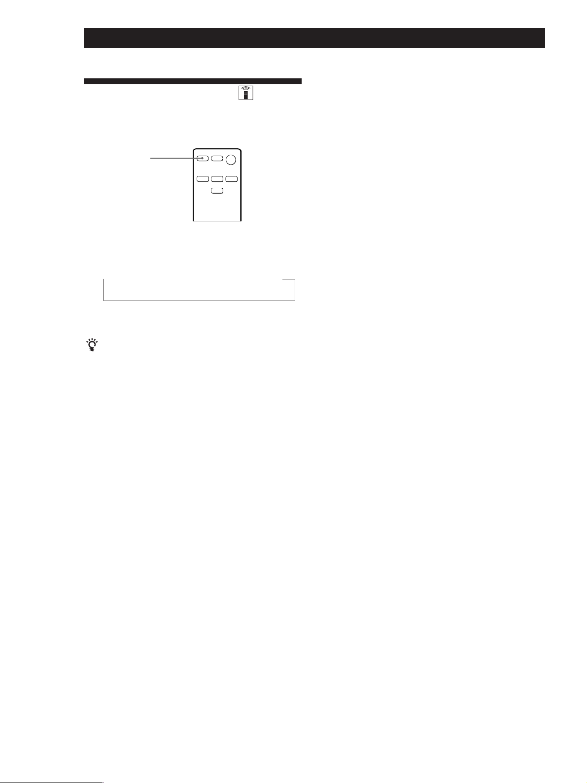
Using the Sleep Timer
You can set the amplifier to turn off automatically at a
time you specify.
SLEEP
Press SLEEP on the remote while the power is on.
Each time you press SLEEP, the time changes as shown
below.
t 2:00:00 t 1:30:00 t 1:00:00 t 0:30:00 t OFF
The display dims after you specify the time.
You can check the time remaining before the
amplifier turns off
Press SLEEP on the remote. The remaining time appears
in the display.
14
GB
Page 15
Using Surround Sound
Choosing a Sound Field
You can take advantage of surround sound simply by
selecting one of the three pre-programmed sound field
according to the type of programme you wish to play.
Sound field indicators
SOUND FIELD
Using Surround Sound
You can find Dolby Surround-encoded software by
looking at the packaging
However, some videos and laser discs may use Dolby
Surround sound even if it’s not indicated on the
package.
Note
Surround sound is turned off when you select the
5.1 CH/DVD.
Adjusting the effect level
(for C. STUDIO and SIMULATED only)
You can make the surround sound more prominent by
increasing the EFFECT level. This control lets you
adjust the “presence” of the surround effect in six steps
(1-6).
SOUND FIELD
ON/OFF
SOUND FIELD
MODE
EFFECT/
DELAY –/+
1 Press SOUND FIELD or SOUND FIELD ON/OFF
on the remote to turn on the sound field.
One of the SOUND FIELD indicators lights up in
the display.
2 Press SOUND FIELD or SOUND FIELD MODE
on the remote repeatedly until the indicator for
the sound field you want lights up.
Select the appropriate sound field as follows:
Select
PRO LOGIC*
C. STUDIO
(Cinema Studio)
SIMULATED
To
Decodes programmes processed
with Dolby Pro Logic Surround.
Reproduces the sound characteristics
of a movie theater. Good for
watching standard movies.
Create a simulated surround sound
from monaural sources such as old
movies or TV programmes.
1 Start playing a programme source.
2 Use EFFECT/DELAY (–/+) on the remote to
select the level you prefer. The effect level is
indicated on the display.
Note
Changing the effect level may not produce major variations
in the surround effect when used with certain playback
sources.
* “DOLBY PL” appears on the display.
To turn off sound field
Press SOUND FIELD ON/OFF on the remote or press
SOUND FIELD repeatedly until “SF OFF” appears on the
display.
15
GB
Page 16
Using Surround Sound
Getting the Most Out of Dolby
Pro Logic Surround Sound
To obtain the best possible Dolby Pro Logic Surround
sound, first select the center mode according to the
speaker system you have. Then, adjust the volume of
each speaker.
Note that you must connect the rear speakers and/or
one center speaker to do the following adjustments.
Selecting the center mode
The amplifier offers you four center modes: Phantom,
Wide, Normal and 3 Stereo. Each mode is designed for
a different speaker configuration.
1 Press SOUND FIELD repeatedly to select the PRO
LOGIC sound field.
2 Press CENTER MODE repeatedly until the
indicator for the center mode you want lights in
the display.
Select the center mode as follows:
Center mode
indicators
SOUND FIELD
ON/OFF
TEST TONE
REAR
LEVEL +/–
Display
Sound field
indicators
SOUND FIELDCENTER MODE
SOUND FIELD
MODE
EFFECT/
DELAY –/+
CENTER
LEVEL +/–
If you have
Front and rear
speakers, no
center speaker
Front and rear
speakers, and
a large center
speaker
Front and rear
speakers, and
a small center
speaker
Front and center
speakers, no rear
speaker
Select
PHANTOM
WIDE
NORMAL
3 STEREO
(3 Channel Logic)
So that
The sound of the
center channel is
output from the front
speakers.
The center channel
fully reproduces the
entire audio spectrum
The bass sound of the
center channel is
output from the front
speakers.
The sound of the rear
channel is output
from the front
speakers.
Notes
• To match the speaker system that is packed together with
this amplifier, we recommend that you set the center
mode to NORMAL or WIDE and turn on the subwoofer.
• If you are using a different speaker system, select the
mode that best suits your speaker system’s configuration.
16
GB
Page 17
Using Surround Sound
Adjusting the speaker volume
The test tone feature lets you set the volume of your
speakers to the same level.
Using the controls on the remote lets you test the
speaker connection and adjust the volume level from
your listening position.
1 Press SOUND FIELD repeatedly to select
“DOLBY PL” and set the center mode to
NORMAL.
2 Press TEST TONE on the remote.
You will hear the test tone from each speaker
sequentially.
3 Adjust the volume level so that the test tone from
each speaker is at the same level from your
listening position.
• To adjust the level of center speaker, press
CENTER LEVEL + or – on the remote.
• To adjust the level of rear speakers, press
REAR LEVEL + or – on the remote.
The center and rear levels are indicated on the
display.
Adjusting the delay time
You can make the surround sound more effective by
delaying the output from the rear speakers (delay
time). You can select from three delay times, S (15 mS),
M (20 mS), and L (30 mS). For example, if you’ve
placed the rear speakers in a large room or apart from
your listening position, set the delay time shorter.
1 Start playing a programme source encoded with
Dolby Surround sound.
2 Press SOUND FIELD repeatedly to select
“DOLBY PL” and set the center mode to
NORMAL.
3 Press EFFECT/DELAY (–/+) on the remote
repeatedly to choose the delay time parameter.
The current delay time appears in the display,
such as “DELAY S,” “DELAY M” or “DELAY L.”
Note
If the AC power cord is disconnected for about one week,
amplifier’s surround parameter will be reset to the factory
settings.
4 Press TEST TONE on the remote to turn off the
test tone.
You can adjust all speakers at one time
Adjust MASTER VOL on the remote or MASTER
VOLUME on the amplifier.
You can increase the output level of the rear
speakers
The adjustment range of the rear speakers is preset from
–10 to +6, but you can shift the range up 3 levels (–7 to
+9). Hold down SOUND FIELD on the amplifier while
turning on the power until “NORMAL” appears on the
display.
The values for the rear level remain fixed at –10 to +6 in
the display, but you will be able to hear the difference in
the actual output level.
To reset the rear level adjustment range, repeat this
procedure to display “GAIN LOW”.
Note
During 5.1 CH/DVD mode, CENTER LEVEL and REAR
LEVEL cannot be adjusted.
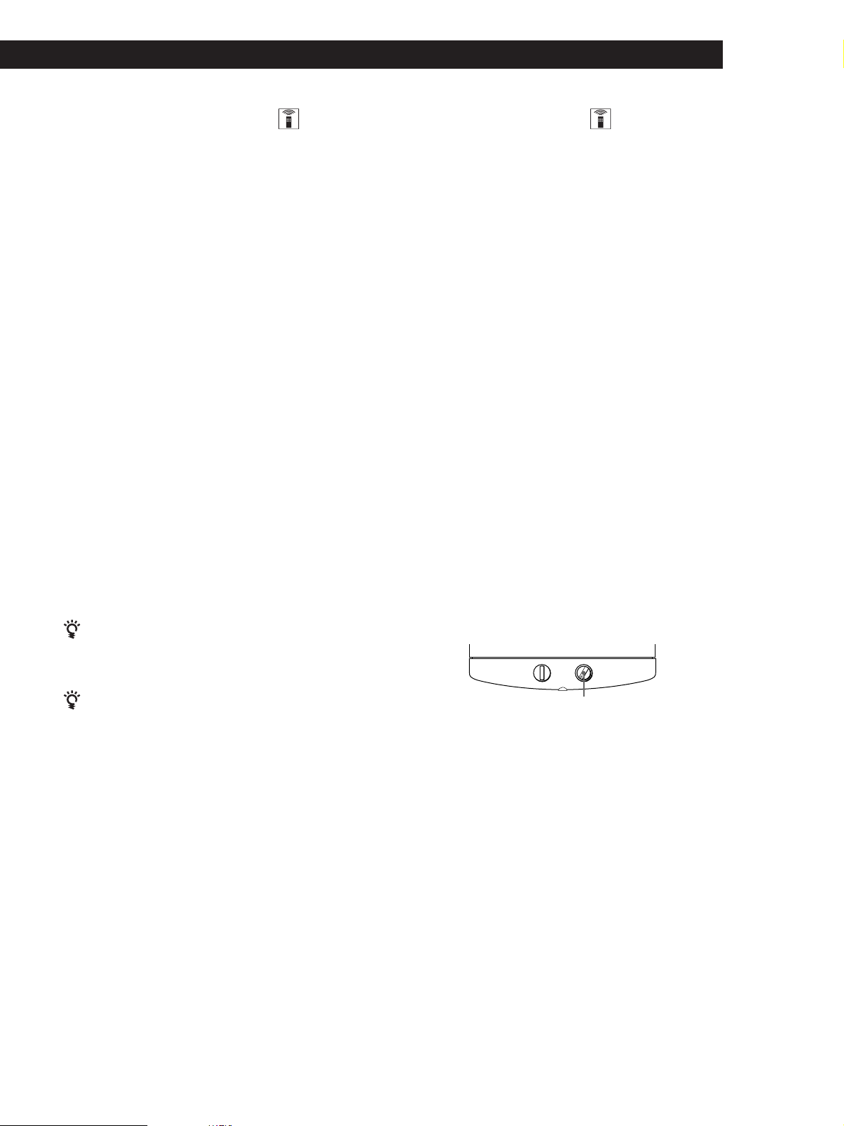
Adjusting the subwoofer
Slight adjustments to the system can enhance your
sound enjoyment.
LEVEL
POWER
MIN MAX
LEVEL
1 Rotate LEVEL to adjust the volume.
Set the volume level to best suit your preference
according to the programme source.
Note
To enjoy high-quality sound, do not turn the subwoofer
volume too high.
17
GB
Page 18

Additional Information
Additional Information
Troubleshooting
If you experience any of the following difficulties while
using the home theater system, use this
troubleshooting guide to help you remedy the
problem. Should any problem persist, consult your
nearest Sony dealer.
There’s no sound or only a very low-level sound is heard.
, Check that the speakers and components are
connected securely.
, Press MUTING on the remote if the MUTING
indicator turns on.
, Make sure you select the correct component
on the amplifier.
, Check whether or not you used the
appropriate AV cables.
, The protective device on the amplifier has
been activated because of a short circuit.
(“PROTECT” flashes.) Turn off the amplifier,
eliminate the short-circuit problem and turn
on the power again.
The left and right sounds are unbalanced or reversed.
, Check that the speakers and components are
connected correctly and securely.
Severe hum or noise is heard.
, Check that the speakers and components are
connected securely.
, Check that the connecting cords are away
from a transformer or motor, and at least 3
meters (10 feet) away from a TV set or
fluorescent light.
, Place your TV away from the audio
components.
, The plugs and jacks are dirty. Wipe them
with a cloth slightly moistened with alcohol.
No sound is heard from the center speaker.
, Select the appropriate center mode (see page
16).
, Adjust the speaker volume appropriately (see
page 17).
No sound or only a very low-level sound is heard from
the subwoofer.
, Make sure you turn on the subwoofer.
, Make sure the connection is made correctly.
The sound has suddenly stopped.
, Make sure all the connections have been
correctly made. Contact between bare speaker
wires at the speaker terminals may cause a
short-circuit.
Surround effect cannot be obtained.
, Make sure you turn on the sound field
function.
No picture or an unclear picture is seen on the TV screen.
, Select the appropriate input on your TV.
, Select the appropriate component on the
amplifier.
The remote does not function.
, Point the remote at the remote sensor g on
the amplifier.
, Remove the obstacles in the path of the
remote and the amplifier.
, Replace both batteries in the remote with new
ones if they are weak.
, Make sure you select the correct function on
the remote.
18
No sound or only a very low-level sound is heard from
the rear speakers.
, Select the appropriate center mode (see page
16).
, Adjust the speaker volume appropriately (see
page 17).
, Make sure you turn on the sound field
surround mode function.
Note
The Dolby Surround effect is dependent on the software
and center mode being used.
GB
Page 19

Additional Information
Specifications
Amplifier section
Power output
Rated Power
Output at Stereo
mode
Reference
Power Output
Frequency
response
Inputs
TV,
VIDEO,
DVD 2CH,
5.1 CH/
DVD
Outputs
Muting
General
Power
requirements
(DIN 1 kHz, 8 ohms)
25 W + 25 W
(DIN 1 kHz, 8 ohms)
Front: 25 W / ch
Center: 25 W
Rear: 25 W / ch
TV, VIDEO, DVD 2CH,
5.1 CH/DVD :
10 Hz - 50 kHz +0.5/–2 dB
Sensitivity
250 mV
Impedance
50
kilohms
WOOFER:
Voltage: 1 V
Impedance: 1 kilohms
Full mute
220 - 230 V AC, 50/60 Hz
S/N
(weighting
network,
input level)
85 dB*
(A, 250 mV)
*78 IHF
Speaker section
SS-MS215 Front, center and rear
speakers
Speaker system
Speaker units
Enclosure type
Rated
impedance
Power handling
capacity
(Maximum input
power)
Sensitivity level
Frequency range
Dimensions
(w/h/d)
Mass
Full range, magnetically
shielded
5 cm cone type
Bass reflex
8 ohms
60 watts
84 dB (1 W, 1m)
150 Hz - 20, 000 Hz
Approx. 76 x 100 x 86 mm
including front grille
Approx. 425 g
SA-WMS215 Subwoofer
System
Speaker system
Speaker unit
Enclosure type
Continuous RMS
power output
(8 ohms, 20 250 Hz)
Reproduction
frequency range
High frequency
cut-off
frequency
Active subwoofer,
magnetically shielded
Woofer: 16 cm cone type
Acoustically Loaded Bass
Reflex
50 W
32 Hz - 250 Hz
250 Hz
Input
LINE IN (input pin jack)
General
Power
requirements
Power
consumptions
Dimensions
(w/h/d)
Mass
Supplied
accessories
Design and specifications are subject to
change without notice.
220 - 230 V AC, 50/60 Hz
45 W
Approx. 240 x 285 x 355
mm including front
panel
Approx. 8 kg
See page 4.
Power
consumption
Dimensions
Mass (Approx.)
115 W
430 x 274 x 64.5 mm
4.6 kg
Specifications indicated are measured at
230 VAC, 50Hz.
19
GB
Page 20
Additional Information
Glossary
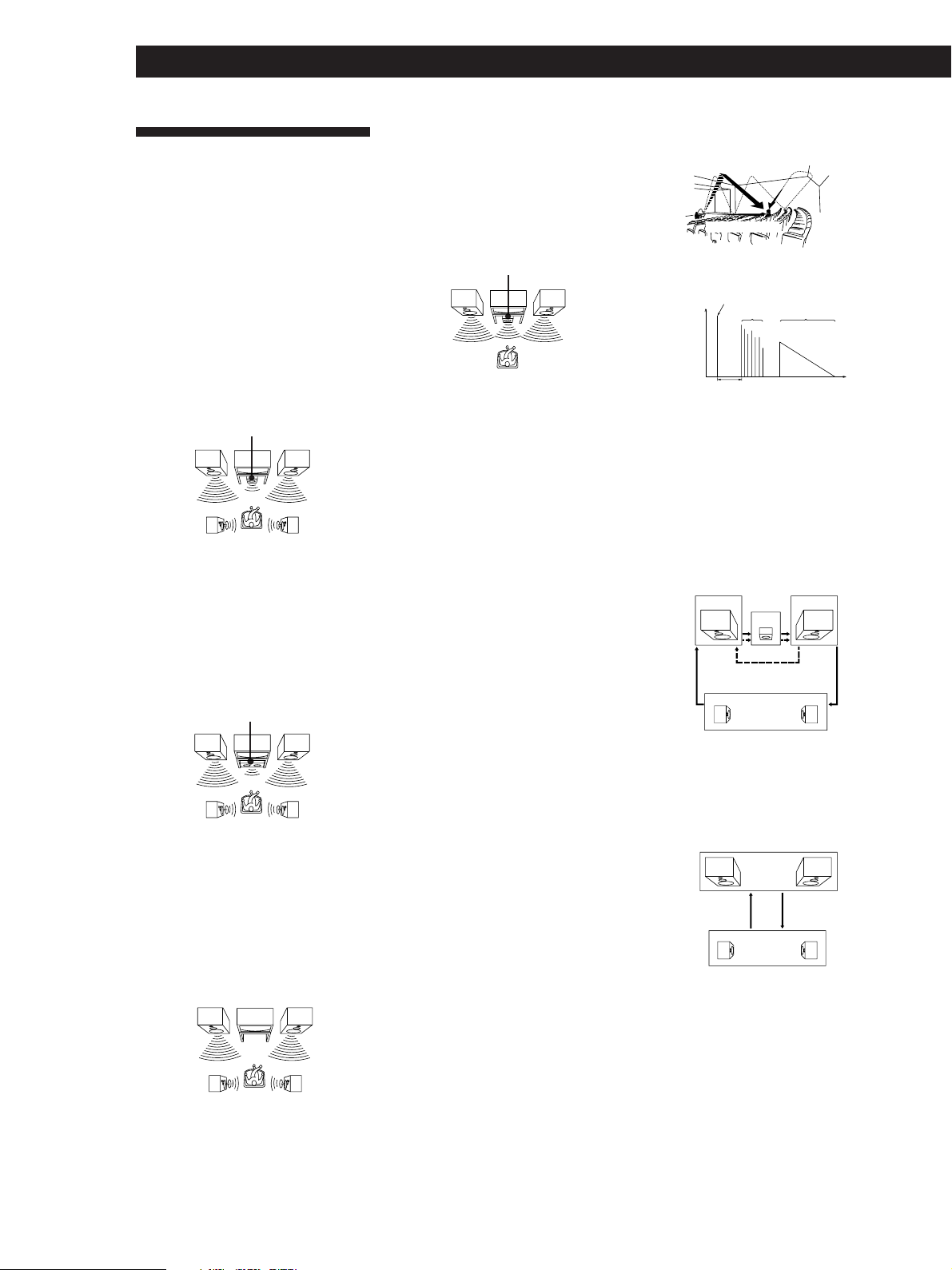
Center mode
Setting of speakers to enhance Dolby Pro
Logic Surround mode. To obtain the best
possible surround sound, select one of the
following four center modes according to
your speaker system.
• NORMAL mode
Select NORMAL mode if you have front
and rear speakers and a small center
speaker. Since a small speaker cannot
produce enough bass, the bass sound of
the center channel is output from the front
speakers.
Front
speaker (L)
speaker (L)
Center
speaker
Rear
• WIDE mode
Select WIDE mode if you have front and
rear speakers and a large center speaker.
With the WIDE mode, you can take full
advantage of Dolby Surround sound.
Front
speaker (L)
Center
speaker
Rear
speaker (L)
• PHANTOM mode
Select PHANTOM mode if you have front
and rear speakers but no center speaker.
The sound of the center channel is output
from the front speakers.
Front
speaker (L)
Front
speaker (R)
Rear
speaker (R)
Front
speaker (R)
Rear
speaker (R)
Front
speaker (R)
• 3 STEREO (3 CH LOGIC)
Select 3 STEREO mode if you have front
and center speakers but no rear speaker.
The sound of the rear channel is output
from the front speakers to let you
experience some of the surround sound
without using rear speakers.
Center
Front
speaker (L)
speaker
Front
speaker (R)
Dolby Pro Logic Surround
Decoding system of Dolby Surround sound
standardized in TV programmes and movies.
Compared with the former Dolby Surround
system, Dolby Pro Logic Surround improves
sound image by using four separate channels:
off-screen audio effects, on-screen dialog, leftto-right panning, and music. These channels
manipulate the sound to be heard and
enhance the action as it happens on the
screen. To take advantage of Dolby Pro Logic,
you should have at least one pair of rear
speakers and/or one center speaker. You also
need to select the appropriate center mode to
enjoy a full effect.
Dolby Digital (AC-3)
This surround format is more advanced than
Dolby Pro Logic Surround. In this format, the
rear speakers output stereo sound with an
expanded frequency range and a subwoofer
channel for deep bass is independantly
provided. This format is also called “5.1”
because the subwoofer channel is counted as
0.1 channel (since it functions only when a
deep bass effect is needed.)
All six channels in this format are recorded
separately to realize superior channel
separation. Furthermore, since all the signals
are processed digitally, less signal
degradation occurs. The name “AC-3” comes
from the fact that it is the third audio coding
method to be developed by the Dolby
Laboratories Licensing Corporation.
5.1 CH/DVD jacks
These jacks are used to input decoded Dolby
Digital (AC-3) audio signals, allowing you to
enjoy 5.1 channel surround sound. Use these
jacks to connect a Dolby Digital (AC-3)
decoder or a DVD player with a built-in AC-3
decoder.
• Types of sound
Early reflections
Direct sound
Reverberation
• Transition of sound from rear speakers
Direct sound
Level
Early reflection time
Early
reflections
Reverberation
Time
Test tone
Signal given out by the amplifier for
adjusting the speaker volume. The test tone
will come out as follows:
• In a system with a center speaker
(NORMAL/WIDE/3 STEREO modes)
The test tone is output from the front L
(left), center, front R (right), and rear
speakers in succession.
Front (L)
3 STEREO
Rear (L, R)
NORMAL/WIDE
Front (R)
Center
• In a system without a center speaker
(PHANTOM mode)
The test tone is output from the front and
the rear speakers alternately.
Front (L, R)
PHANTOM
Rear (L, R)
20
GB
Rear
speaker (L)
Rear
speaker (R)
Surround sound
Sound that consists of three elements: direct
sound, early reflected sound (early
reflections) and reverberative sound
(reverberation). The acoustics where you hear
the sound affect the way these three sound
elements are heard. These sound elements are
combined in such a way that you can actually
feel the size and the type of a concert hall.
Page 21

Additional Information
Remote Button Description
For buttons not described on previous pages and
buttons with names different from the buttons on the
main unit.
Remote
Button
m/M
./>
X
N
x
AV/
?/1
ENTER/
EXECUTE
ANT TV/
VTR
MENU
TITLE
EXIT/
RETURN
DISPLAY
>
>
>
<
Operates
VCR/DVD/
CD/LDP
DVD/CD/
LDP
VCR/DVD/
CD/LDP
VCR/DVD/
CD/LDP
VCR/DVD/
CD/LDP
TV/VCR/
DVD/LDP
TV/VCR/
DVD
VCR
TV/VCR/
DVD
DVD
TV/DVD
TV/DVD/
LDP
TV/VCR/
DVD
TV/VCR/
DVD
TV/VCR/
DVD
TV/VCR/
DVD
Function
Fast forwards or rewinds.
Skips tracks.
Pauses play.
Starts play.
Stops play.
Turns on or off the power.
Confirm setting.
Selects output signal from
the antenna terminal: TV
signal or VCR programme.
Display menu.
Display current DVD title.
Exit from menu mode or
return to previous screen.
Selects information
displayed on the TV
screen.
To increase a value or
move the cursor upwards
on the menu screen such
as VIDEO CONTROL/
AUDIO CONTROL/SET
UP/LANGUAGE/DEMO
To decrease a value or
move the cursor
downwards on the menu
screen such as VIDEO
CONTROL/AUDIO
CONTROL/SET UP/
LANGUAGE/DEMO
To move the cursor to the
right side of the menu
screen.
To move the cursor to the
left side of the menu
screen.
Remote
Operates
Function
Button
VTR CH
+/–
TV CH
+/–
TV VOL
+/–
* The MENU control keys may not operate on certain Sony
TVs.
VCR
TV
TV
VCR channel selection.
TV channel selection.
To adjust the TV volume.
21
GB
Page 22
Additional Information
Index
Index
A, B
Adjusting
speaker volume 17
volume 11
C
Center mode 16, 20
NORMAL mode 16, 20
PHANTOM mode 16, 20
3 STEREO mode 16, 20
WIDE mode 16, 20
Connecting. See Hookups
D, E, F, G
Dolby Digital (AC-3) 20
Dolby Pro Logic
Surround 20
getting the most out of 16
Dolby Surround sound 15, 20
center mode 16, 20
H, I, J, K, L, M
Hookups
mains lead 9
overview 4
speakers 7
video component 5
N, O
NORMAL mode 16, 20
P, Q
PHANTOM mode 16, 20
Programme source
selecting 11
R
Rear panel 5, 6, 9, 22
Remote buttons 12, 13, 21
S
Selecting a programme source
11
using the remote 12
Sleep timer 14
Sound field 13, 14
Speakers
connection 7
impedance 19
placement 8
T
Test tone 16, 20
3 STEREO mode 16, 20
Troubleshooting 18
U
Unpacking 4
V
Video Component Hookups 5
W, X, Y, Z
Watching video programmes
11
WIDE mode 16, 20
22
GB
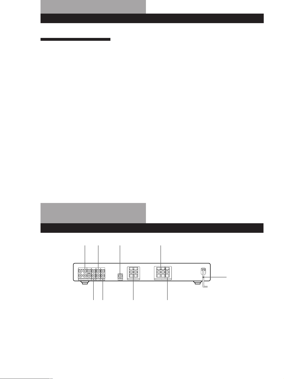
Rear Panel Descriptions
15 7
3
1 5.1 CH/DVD
2 DVD 2CH
3 TV
4 VIDEO
5 WOOFER
6 FRONT SPEAKERS
9
8642
7 REAR SPEAKERS
8 CENTER SPEAKER
9 Mains lead
Page 23

Préparatifs
Fonctionnement
AVERTISSEMENT
Afin d’éviter tout risque
d’incendie ou
d’électrocution, éviter
d’exposer l’appareil à la
pluie ou à l’humidité.
Afin d’écarter tout risque
d’électrocution, garder le coffret fermé.
Ne confier l’entretien de l’appareil qu’à
un personnel qualifié.
Précautions
Sécurité
• Si un solide ou un liquide tombait
dans le coffret, débranchez
l’amplificateur et faites-le vérifier par
un technicien qualifié avant de le
remettre en service.
Sources d’alimentation
• Avant de mettre l’amplificateur en
service, vérifiez que sa tension de
fonctionnement correspond à celle du
courant secteur local. La tension de
fonctionnement est indiquée sur la
plaque signalétique à l’arrière de
l’amplificateur.
• L’amplificateur n’est pas déconnecté
de la source d’alimentation tant qu’il
est branché sur une prise murale
(secteur), même si vous le mettez hors
tension.
• Si vous ne comptez pas utiliser
l’amplificateur pendant un certain
temps, débranchez-le de la prise
murale. Pour débrancher le cordon,
tirez sur la fiche et jamais sur le
cordon proprement dit.
• Si le cordon d’alimentation secteur
doit être remplacé, faites appel à un
professionnel uniquement.
• L’interrupteur d’alimentation se
trouve sur le panneau avant.
Installation
• N’installez pas l’amplificateur dans
un espace confiné, comme dans une
bibliothèque ou un meuble encastré.
• Installez l’amplificateur dans un
endroit bien ventilé pour éviter tout
risque de surchauffe interne et
prolonger la durée de vie des
composants.
• N’installez pas l’amplificateur près
d’une source de chaleur, dans un
endroit en plein soleil, poussiéreux
ou exposé à des chocs mécaniques.
• Ne posez rien sur le coffret qui puisse
bloquer les orifices de ventilation et
provoquer un mauvais
fonctionnement.
• N’installez pas les enceintes dans une
position inclinée.
• Ne laissez pas les enceintes dans un
endroit :
– Extrêmement chaud ou froid
– Poussiéreux ou sale
– Très humide
– Sujet à des vibrations
FR
2
– Exposé à la lumière directe du soleil
• Avant de raccorder d’autres
appareils, mettez l’amplificateur hors
tension et débranchez-le.
• Ne poussez pas le système
d’enceintes à une puissance excédant
la capacité d’entrée maximum du
système.
• Si la polarité des connexions de
l’enceinte n’est pas correcte, les
tonalités graves seront faibles et la
position des différents instruments
pourra paraître instable.
• Le contact de deux fils d’enceintes
dénudés au niveau des bornes de
l’enceinte peut provoquer un courtcircuit.
• La grille de l’enceinte ne peut pas être
retirée. Ne tentez pas de retirer la
grille de l’enceinte. Si vous essayez de
la retirer, vous risquez
d’endommager l’enceinte.
Si les couleurs des images d’un
téléviseur proches sont instables
Cette enceinte possède un blindage
magnétique afin de pouvoir être
installée près d’un téléviseur.
Cependant, il est possible que des
irrégularités de couleurs puissent
toutefois être observées sur certains
téléviseurs.
Si des irrégularités de couleurs sont
observées...
p Eteignez le téléviseur, puis
rallumez-le après 15 ou 30 minutes.
Si des irrégularités de couleurs sont
toujours observées...
p Eloignez les enceintes du
téléviseur.
Si un sifflement se produit
Repositionnez les enceintes ou baissez
le volume de l’amplificateur.
Nettoyage
• Nettoyez le coffret, le panneau et les
commandes avec un chiffon doux
légèrement imprégné d’une solution
détergente neutre. N’utilisez pas de
tampon abrasif, poudre à récurer ou
solvant, comme de l’alcool ou de la
benzine.
En cas de question ou de problème
concernant l’amplificateur,
consultez le revendeur Sony le plus
proche.
Page 24
Préparatifs
Au sujet de ce
manuel
Conventions
• Les instructions fournies dans ce
manuel décrivent les commandes de
l’amplificateur et des enceintes. Vous
pouvez également utiliser les
commandes de la télécommande qui
ont un nom identique ou similaire à
celles de l’amplificateur.
• Les icônes suivants sont utilisés dans
ce manuel:
Indique que vous ne pouvez
utiliser que la télécommande
pour effectuer cette opération.
Donne des conseils
supplémentaires pour faciliter
l’utilisation.
Cet amplificateur intègre un décodeur
Dolby Pro Logic Surround.
Fabriqué sous licence de Dolby
Laboratories.
DOLBY, AC-3, PRO LOGIC et le
symbole double-D ; sont des marques
de Dolby Laboratories.
TABLE DES MATIÈRES
Préparatifs
Déballage 4
Description des raccordements 4
Raccordement de composants video 5
Raccordements et configurations des enceintes 6
Raccordement au courant secteur 9
Avant la mise en service de l’amplificateur 10
Fonctionnement de l’amplificateur
Sélection d’un composant 11
Changement des réglages usine des touches de fonction 13
Utilisation du programmateur d’extinction 14
Ecoute du son surround
Sélection d’un champ sonore 15
Utilisation optimale du son surround Dolby Pro Logic 16
Informations supplémentaires
Guide de dépannage 18
Spécifications 19
Glossaire 20
Nomenclature de la télécommande 21
GB
FR
NL
SE
Maintenez ?/1 enfoncée et appuyez
sur CENTER MODE pour changer la
configuration de contrôle du
ventilateur. Chaque fois que vous
suivez la procédure présentée cidessus, la configuration suivante
apparaît.
Sélectionnez Pour
FAN ON Activer le ventilateur
en permanence.
FAN AUTO Active
automatiquement le
ventilateur lorsque la
sortie des haut-parleurs
est suffisante.
Index 22
Description du panneau arrière 22
FR
3
Page 25
PréparatifsPréparatifs
Déballage
Vérifiez si les accessoires suivants sont fournis avec
l’amplificateur:
• Télécommande (1)
• Piles de format AA (R6) (2)
• Adaptateur de raccord (1)
• Enceintes (5)
• Enceinte avant (2)
• Enceinte arrière (2)
• Enceinte centrale (1)
• Caisson de grave amplifié (1)
• Cordon de raccordement de l’enceinte, 10 m (2)
• Cordon de raccordement de l’enceinte, 2,5 m (3)
• Cordon de connexion monophonique (1 phono vers
1 phono) (1)
• Blocs (20)
Mise en place des piles dans la
télécommande
Insérez deux piles de format AA (R6) en faisant
correspondre les bornes + et – avec le schéma dans le
logement. Pour utiliser la télécommande, dirigez-la
vers le détecteur infrarouge g sur l’amplificateur.
Description des raccordements
Vous pouvez raccorder les composants video suivants
à l’amplificateur. Selon les composants que vous
voulez raccorder, reportez-vous aux pages indiquées
pour les connexions. Pour plus de détails sur les
différentes prises du processeur, reportez-vous à
“Description du panneau arrière” page 22.
Raccordement de
Raccordement
d’enceintes (6)
Enceinte
avant
(gauche)
Enceinte
arrière
(gauche)
Avant de commencer
composants video (5)
Téléviseur
Magnétoscope
Enceinte
centrale
Caisson de
amplifié
Lecteur
DVD/
décodeur
AC-3
grave
actif
Enceinte
avant
(droite)
Enceinte
arrière
(droite)
]
}
}
]
Quand remplacer les piles
Dans des conditions d’utilisation normales, les piles
durent environ six mois. Quand vous ne pouvez plus
contrôler l’amplificateur avec la télécommande,
remplacez les piles par des neuves.
Remarques
• Ne laissez pas la télécommande dans un endroit
extrêmement chaud ou humide.
• N’utilisez pas une pile neuve avec une vieille pile.
• Ne pas exposer le détecteur infrarouge aux rayons directs
du soleil ou à un éclairage pour éviter tout mauvais
fonctionnement.
• Si vous prévoyez de ne pas utiliser la télécommande
pendant longtemps, enlevez les piles pour éviter tout
dommage dû à une fuite d’électrolyte et à la corrosion.
• Mettez tous les composants hors tension avant
d’effectuer les connexions.
• Effectuez toutes les connexions avant de brancher le
cordon d’alimentation secteur.
• Enfoncez les fiches correctement pour éviter un
bourdonnement et du bruit.
• Lors du raccordement d’un cordon audio, faites
correspondre les fiches codées par couleur aux prises
des composants: blanc (audio, gauche) à blanc et
rouge (audio, droit) à rouge.
FR
4
Page 26
Raccordement de composants
video
Aperçu
Ce paragraphe explique comment raccorder des
composants vidéo à l’amplificateur. L’illustration cidessous indique l’emplacement des prises.
5.1CH/DVD TV
DVD 2CH
De quelles cordons avez-vous besoin?
• Adaptateur de raccord (fourni)
• Euro AV cable (non fourni) (1 pour chaque, téléviseur ou
magnétoscope)
• Vouz avez besoin de cordons audio (non fourni) (1 pour
lecteur de DVD, 2 pour les prises FRONT et REAR du
décodeur AC-3)
VIDEO
Préparatifs
Raccordements
La flèche l indique le sens du signal.
Téléviseur/magnétoscope
Vous pouvez écouter le son du magnétoscope ou du
téléviseur en raccordant le signal audio du
magnétoscope ou du téléviseur à l'amplificateur.
Vers l'entrée
de l'audio du
magnétoscope
Vers l'entrée
de l'audio du
téléviseur
Euro AV cable (non
fourni)
ç
ç
Amplificateur
VIDEO AUDIO IN
Blanc
(gauche)
Rouge
(droit)
Blanc
(gauche)
Rouge
(droit)
TV
VTRTV
L
R
L
R
Blanc (gauche)
Rouge (droit)
Blanc (gauche)
Rouge (droit)
• Cordons audio monauraux (non fournis)
(2 pour les prises CENTER et WOOFER du décodeur
AC-3)
Noir
Noir
Adaptateur
de raccord
(fourni)
n
du TV
Si vous possédez un autre appareil, comme par exemple
un deuxième magnétoscope ou un lecteur LD, branchezle aux prises DVD 2CH.
Lecteur de DVD
Si votre lecteur de DVD ne possède pas de sortie 5,1
canaux (5.1 CH), connectez les prises de sortie audio du
lecteur de DVD aux prises DVD 2CH de
l’amplificateur.
Amplificateur
DVD 2CH
AUDIO IN
LL
DVD 2CH
Lecteur de DVD
AUDIO OUT
AUDIO OUT
L
RR
(continuer page suivante)
FR
5
Page 27

Préparatifs
Lecteur de DVD avec décodeur AC-3
Si vous avez un décodeur Dolby Digital (AC-3) ou un
lecteur de DVD avec décodeur AC-3 intégré, vous
pouvez reproduire les pistes sonores Dolby Digital
(AC-3) décodées avec les enceintes raccordées à
l’amplificateur. Raccorder le décodeur de la façon
suivante.
Amplificateur
5.1 CH/DVD
FRONT
L L
L
CENTER
REAR
L
WOOFER
5.1CH / DVD
L
L
Décodeur Dolby
Digital AC-3 (etc.)
PRE OUT
REAR
CENTER
WOOFER
5.1CH OUTPUT
FRONT
Raccordements et
configurations des enceintes
Aperçu
Cette section décrit comment brancher les enceintes
fournies (SS-MS215) à l’amplificateur. Le raccordement
du caisson de grave amplifié actif (SA-WMS215)
améliorera la reproduction des graves.
L’illustration ci-dessous indique l’emplacement des
bornes de l’amplificateur.
RR
FRONT
SPEAKERS
CENTER
SPEAKER
WOOFER
(AUDIO OUT)
REAR
SPEAKERS
De quels cordons avez-vous besoin?
• Cordon de raccordement de l’enceinte (fourni) (1 pour
chaque enceinte)
(+)(+)
(–)
• Cordon de connexion monophonique (fourni)
(–)
NoirNoir
FR
6
Page 28

Préparatifs
R
EA
R
+
–
RL
RL
REAR
+
–
R
L
RL
Raccordements
Enceintes avant (SS-MS215)
Enceinte avant
(droite)
Amplificateur
R-FRONT-L
SPEAKERS
Enceintes centrale et arrière (SS-MS215)
Enceinte
arrière (droite)
Amplificateur
R-REAR-L CENTER
SPEAKERS
Remarques
• Veillez à faire correspondre les bornes des cordons
d’enceintes aux bornes des composants: + à + et – à –. Si
les cordons sont inversés, le son sera déformé et les graves
feront défaut.
• Assurez-vous que toutes les connexions sont fermes. Le
contact de deux fils d’enceintes dénudés au niveau des
terminaux de l’enceinte peut provoquer un court-circuit.
Enceinte avant
(gauche)
Enceinte
centrale
Enceinte
arrière
(gauche)
Pour éviter de court-circuiter les enceintes
Court-circuiter les enceintes peut endommager
l’amplificateur. Pour éviter que cela ne se produise,
prenez les précautions suivantes lors de la connexion
des enceintes. Vérifiez que l’extrémité dénudée de
chaque cordon d’enceinte ne touche aucune autre prise
d’enceinte ou une autre extrémité dénudée d’un autre
cordon d’enceinte.
Exemples de cordons d’enceinte mal installés:
L’extrémité dénudée du cordon d’enceinte touche une
autre prise d’enceinte.
Les extrémités dénudées de plusieurs cordons d’enceinte
se touchent parce qu’une partie trop importante d’isolant
a été retirée.
Après avoir connecté tous les appareils, les enceintes et
le cordon d’alimentation secteur, sortez une tonalité de
test pour vérifier que toutes les enceintes sont
connectées correctement. Pour savoir comment sortir
une tonalité de test, référez-vous à “Ajustement du
volume des enceintes” à la page 17.
Si vous avez connecté des enceintes arrière, assurezvous d’appuyez sur le bouton 5.1 CH/DVD sur
l’amplificateur avant de sortir la tonalité de test de
façon que la tonalité soit sortie indépendamment de
l’enceinte arrière gauche et de l’enceinte arrière droite.
Si aucun son n’est entendu d’une enceinte lors de la
sortie de la tonalité de test, ou si la tonalité de test est
sortie d’une enceinte qui ne correspond pas au nom
affiché sur l’amplificateur, les enceintes sont peut-être
court-circuitées. Si cela se produit, vérifiez de nouveau
la connexion des enceintes.
(continuer page suivante)
FR
7
Page 29

Préparatifs
Caisson de grave amplifié actif (SA-WMS215)
Caisson de grave
amplifié actif
Amplificateur
AUDIO OUT
WOOFER
INPUT
Attention
• L’unité d’enceinte du caisson de grave amplifié actif est
située dans la partie inférieure du caisson.
• Evitez tout contact avec cette unité, démunie de toute
protection.
• Placez le caisson de grave amplifié actif sur une surface
plate afin d’éviter tout endommagement de l’unité
d’enceinte.
Placement des enceintes
Emplacement de chaque enceinte
Centrale
Caisson de
grave amplifié
Avant
(gauche)
Arrière
(gauche)
Chaque enceinte devra être orientée face à la position
d’écoute. Vous bénéficierez d’une meilleure restitution
sonore si toutes les enceintes sont toutes à distance
égale de la position d’écoute.
Placez les enceintes avant à une distance appropriée de
part et d’autre du téléviseur.
Placez le caisson de grave amplifié d’un côté ou de
l’autre du téléviseur.
Placez l’enceinte centrale sur le téléviseur.
L’emplacement des enceintes arrière dépend de la
configuration de votre pièce. Elles pourront
indifféremment être placées de part et d’autre de la
position d’écoute A ou derrière la position d’écoute
B.
Avant
(droite)
Arrière
(droite)
Installation des enceintes
Afin d’empêcher tout phénomène de vibrations ou de
déplacement pendant l’écoute, fixez les blocs au quatre
coins de l’enceinte centrale et des enceintes avant et
arrière.
Enceintes Avant/
Centrale/Arrière
Blocs
FR
8
Page 30

Installation de l’enceinte centrale
Installez fermement l’enceinte centrale sur votre
téléviseur, en vous assurant qu’elle est bien à niveau.
Blocs
Installation des autres enceintes
Afin de bénéficier d’une plus grande flexibilité dans le
placement des enceintes, utilisez les pieds d’enceintes
WS-FV10, WS-TV10 ou WS-WV10 en option
(disponibles dans certains pays).
Préparatifs
Raccordement au courant
secteur
Branchement du cordon d’alimentation
secteur
Branchez le cordon d’alimentation secteur de
l’amplificateur, caisson de grave amplifié actif et des
composants vidéo sur une prise murale.
Amplificateur
/
à une prise
murale
Caisson de grave amplifié actif
WS-FV10 WS-TV10
Remarque
Il n’est pas nécessaire de fixer les pieds si vous utilisez déjà
des supports d’enceintes.
Suggestion
La hauteur des enceintes centrales devra être ajustée en
fonction du centre du téléviseur.
WS-WV10
(pour les
enceintes arrière)
/
à une prise
murale
FR
9
Page 31

Préparatifs
Avant la mise en service de
l’amplificateur
La première fois que vous utilisez l’amplificateur, ou si
vous voulez supprimer tous les préréglages effectués,
annulez la mémoire de l’amplificateur en procédant de
la façon suivante.
?/1 (alimentation)
1 Eteignez l’amplificateur.
2 Appuyez sur ?/1 (alimentation) pendant plus de
4 secondes.
“INITIAL” apparaît sur l’afficheur et les paramètres
suivants sont réinitialisés ou supprimés:
• Tous les préréglages par défaut des champs
sonores sont rétablis.
• La configuration de contrôle de l’enceinte est
rétablie sur FAN ON.
Remarque
Si vous utilisez un lecteur DVD Sony avec ce système de
sonorisation surround, utilisez la configuration suivante
pour votre lecteur DVD :
Haut-parleurs
Avant
Centre
arrière
Caisson de basses
Si vous utilisez un lecteur DVD d’une autre marque,
reportez-vous au mode d’emploi du lecteur pour obtenir
plus d’informations sur l’installation et la configuration des
enceintes.
Réglages
SMALL
SMALL
SMALL
YES
10
FR
Page 32

Sélection d’un composant
Pour écouter un composant raccordé, vous devez
d’abord sélectionner la fonction sur l’amplificateur ou
avec la télécommande.
Avant tout, vérifiez que:
• Vous avez raccordé tous les composants
correctement comme indiqué aux pages 5 to 9.
1/u (alimentation)
Touches de fonction
1 Appuyez sur 1/u (alimentation) pour mettre
l’amplificateur sous tension.
MASTER VOLUME
Fonctionnement de l’amplificateurFonctionnement de l’amplificateur
Pour regarder des programmes vidéo
Pour tirer le meilleur parti des effets surround de
l’amplificateur, tel le Dolby Surround, désactivez les
haut-parleurs du téléviseur. Vous pourrez ainsi utiliser
la télécommande de l’amplificateur pour contrôler le
son.
Pour regarder des émissions de télévision, procédez
comme suit:
1 Allumez le téléviseur.
2 Allumez l’amplificateur et appuyez sur TV.
Pour regarder un signal vidéo ou des DVD, procédez
comme suit:
1 Allumez le téléviseur et réglez l’entrée du
téléviseur sur le composant vidéo que vous
souhaitez regarder.
2 Tournez la commande MASTER VOLUME sur
VOL MIN (indiqué sur l’affichage) pour éviter
d’endommager vos enceintes.
3 Appuyez sur une touche de fonction pour
sélectionner un composant:
Pour regarder
Cassettes vidéo
Programmes de
télévision
DVD (Digital
Versatile Disc)
DVD par le
décodeur AC-3
Pour utiliser la télécommande
Pour les détails, référez-vous à “Utilisation de la
télécommande” à la page 12.
Appuyer sur
VIDEO
TV
DVD 2CH
5.1 CH/DVD
Mode d’entrée
du téléviseur
VIDEO
VIDEO
VIDEO
VIDEO
4 Mettez le composant, par exemple le
magnétoscope, sous tension et commencez la
lecture.
2 Allumez l’amplificateur et appuyez sur une
touche de fonction (VIDEO, DVD 2CH ou 5.1
CH/DVD) pour sélectionner le composant que
vous souhaitez utiliser.
3 Allumez le composant vidéo et démarrez la
lecture.
5 Tournez la commande MASTER VOLUME pour
régler le volume.
Pour
Couper le son
Vous devez
Appuyer sur la touche MUTING
de la télécommande. Appuyez
de nouveau pour rétablir le son.
(continuer page suivante)
11
FR
Page 33

Fonctionnement de l’amplificateur
Utilisation de la télécommande
La télécommande vous permet de contrôler
l’amplificateur et les composants Sony raccordés.
AV ?/1
?/1
SYSTEM
CONTROL/
FUNCTION
1 Appuyez sur une des touches SYSTEM
CONTROL/FUNCTION pour sélectionner le
composant que vous voulez utiliser.
L’amplificateur et le composant sélectionné se
mettent sous tension.
Le tableau suivant indique le réglage usine des
touches SYSTEM CONTROL/FUNCTION de la
télécommande.
Pour reproduire
Des émissions de télévision
Des cassettes vidéo VHS
(mode VTR-3)
Un lecteur de DVD
(pour la lecture 2 canaux)
Lecture DVD/
décodeur AC-3
Appuyez sur
TV
VIDEO
DVD
5.1 CH
Pour mettre les composants hors tension
Appuyez simultanément sur AV ?/1 et ?/1. Cela vous
permet de mettre simultanément hors tension le composant
audio/vidéo Sony. Si le composant ne se met pas hors
tension, appuyez sur l’interrupteur d’alimentation du
composant.
Si vous utilisez un téléviseur Sony
• Le téléviseur se met sous tension et se règle sur
l’entrée vidéo appropriée quand vous appuyez sur la
touche VIDEO. Si le téléviseur ne se règle pas
automatiquement sur l’entrée appropriée, appuyez
sur la touche TV/VIDEO.
• Lors que vous utilisez uniquement le téléviseur,
mettez-le sous tension en utilisant la télécommande
du téléviseur.
Si vous voulez changer le réglage usine d’une touche
Voir “Changement des réglages usine des touches de
fonction” page 13.
Si le composant ne se met pas sous tension
Appuyez sur l’interrupteur d’alimentation sur le
composant.
2 Démarrez la lecture.
Pour plus de détails, voir “Nomenclature de la
telecommande” page 21.
12
FR
Page 34

Changement des réglages
Fonctionnement de l’amplificateur
usine des touches de fonction
Si les réglages usine des touches SYSTEM CONTROL/
FUNCTION (“Utilisation de la télécommande” page
12) ne correspondent pas aux composants de votre
chaîne, vous pouvez les changer. Le tableau suivant
montre les possibilités d’alterner l’affectation des
fonctions de chaque touche.
Touche Affectation possible
VIDEO VTR 1, VTR 2, VTR 3
DVD DVD, LDP, CD
* Le réglage par défaut de VIDEO est VTR 3.
* Les magnétoscopes Sony fonctionnent avec les réglages
VTR 1, 2 ou 3 qui correspondent respectivement aux
formats Beta, 8 mm et VHS.
Réinitialisation du clavier numérique pour la touche de
fonction VIDEO
VTR 1 CURSOR UP
VTR 2 ENTER/EXECUTE
VTR 3 CURSOR DOWN
SYSTEM
CONTROL/
FUNCTION
Touches de
commande
MENU
Par exemple, si vous raccordez un lecteur LD à la prise
DVD, vous pouvez affecter la touche DVD au contrôle
du lecteur LD.
1 Tenez enfoncée la touche SYSTEM CONTROL/
FUNCTION dont vous voulez changer la fonction
(par exemple, DVD).
2 Appuyez sur la touche correspondant au
composant auquel vous voulez affecter la touche
SYSTEM CONTROL/FUNCTION (par exemple,
DISPLAY pour le lecteur LD).
Maintenant, vous pouvez utiliser la touche DVD
pour contrôler votre lecteur LD Sony.
Pour remettre une touche à sa valeur par défaut
Répétez les opérations ci-dessus.
Réinitialisation du clavier numérique pour la touche de
fonction DVD
DVD EXIT/RETURN
LD DISPLAY
CD CURSOR RIGHT
Pour remettre toutes les touches de fonction à leur
valeur par défaut
Appuyez sur ?/1, AV ?/1 et MASTER VOL – en même
temps.
13
FR
Page 35

Fonctionnement de l’amplificateur
Utilisation du
programmateur d’extinction
Vous pouvez régler l’amplificateur pour qu’il se mette
automatiquement hors tension à l’heure que vous
programmez.
SLEEP
Appuyez sur SLEEP sur la télécommande quand l’appareil
sous tension. Chaque fois que vous appuyez sur SLEEP,
l’heure change selon la séquence suivante.
t 2:00:00 t 1:30:00 t 1:00:00 t 0:30:00 t OFF
L’affichage s’assombrit après que vous avez spécifié l’heure.
Vous pouvez vérifier la durée restant avant la mise
hors tension de l’amplificateur
Appuyez sur SLEEP de la télécommande. La durée
restante apparaît dans l’affichage.
14
FR
Page 36

Sélection d’un champ sonore
Vous pouvez profiter pleinement d’un son surround en
sélectionnant simplement un des trois champs sonores
en fonction du type de programme que vous souhaitez
lire.
SOUND FIELD
ON/OFF
Indicateurs de champ sonore
SOUND FIELD
SOUND FIELD
MODE
EFFECT/
DELAY –/+
Ecoute du son surroundEcoute du son surround
Vous pouvez reconnaître un programme enregistré
en Dolby surround grâce à l’indication sur
l’emballage
Cependant, certains disques vidéo et laser sont
enregistrés en Dolby surround même si ce n’est pas
indiqué sur l’emballage.
Remarque
Le son surround est désactivé quand vous sélectionnez 5.1
CH/DVD.
Réglage du niveau de l’effet (pour C.
STUDIO et SIMULATED seulement)
Vous pouvez rendre le surround plus évident en
augmentant le niveau de l’effet (EFFECT). Cette
commande vous permet d’ajuster l’effet sur six niveaux
différents (1-6).
1 Reproduisez une source de programme.
2 Utilisez EFFECT/DELAY (–/+) sur la
télécommande pour sélectionner votre niveau
préféré. Le niveau d’effet est indiqué sur
l’affichage.
1 Appuyez sur SOUND FIELD ou SOUND FIELD
ON/OFF sur la télécommande pour activer le son
surround.
Un des voyants SOUND FIELD s’allume dans
l’affichage.
2 Appuyez plusieurs fois sur SOUND FIELD ou
SOUND FIELD MODE sur la télécommande
jusqu’à ce que le voyant du mode surround que
vous souhaitez utiliser s’allume.
Sélectionnez le mode surround approprié comme
suit :
Sélectionnez
PRO LOGIC*
C. STUDIO
(Studio de
Cinéma)
SIMULATED
* “DOLBY PL” apparaît sur l’affichage.
Pour désactiver le son surround
Appuyez sur SOUND FIELD ON/OFF sur la télécommande
puis appuyez plusieurs fois sur SOUND FIELD jusqu’à ce
que “SF OFF” apparaisse dans l’affichage.
Pour
Décode les programmes codés en
Dolby Pro Logic Surround.
Reproduit les caractéristiques
sonores d’un cinéma. Excellent pour
regarder des films ordinaires.
Simuler un son surround à partir de
sources monophoniques, comme les
films anciens ou certaines émissions
de télévision.
Remarque
Avec certaines sources de lecture, le changement du niveau
d’effet n’est pas toujours accompagné d’un changement
important de l’effet surround.
15
FR
Page 37

Ecoute du son surround
Utilisation optimale du son
surround Dolby Pro Logic
Afin d’obtenir le meilleur effet surround Dolby Pro
Logic possible, sélectionnez d’abord le mode de canal
central en fonction des enceintes utilisées. Ajustez
ensuite le volume de chaque enceinte.
Sélection du mode de canal central
L’amplificateur offre quatre modes avec canal central:
PHANTOM, WIDE, NORMAL et 3 STEREO. Chaque
mode correspond à une configuration d’enceintes
différente.
1 Appuyez plusieurs fois sur SOUND FIELD pour
sélectionner le champ sonore PRO LOGIC.
Vous devez raccorder les enceintes arrière et/ou une
enceinte centrale pour pouvoir effectuer les réglages
suivants.
Indicateurs de
mode central
SOUND FIELD
ON/OFF
TEST TONE
REAR
LEVEL +/–
Affichage
Indicateurs de
champ sonore
SOUND FIELDCENTER MODE
SOUND FIELD
MODE
EFFECT/
DELAY –/+
CENTER
LEVEL +/–
2 Appuyez plusieurs fois sur CENTER MODE
jusqu’à ce que l’indicateur du mode souhaité
apparaisse sur l’affichage. Choisissez un mode en
vous référant au tableau suivant.
Si vous avez
Des enceintes
avant et arrière
mais pas
d’enceinte centrale
Des enceintes
avant et arrière et
une grande
enceinte centrale
Des enceintes
avant et arrière et
une petite enceinte
centrale
Des enceintes
avant et centrale
mais pas
d’enceintes arrière
Remarques
• Pour correspondre au système d’enceintes livré avec cet
amplificateur, nous vous recommandons de régler le
mode central sur NORMAL ou WIDE et mettez le caisson
de grave amplifié sous tension.
• Si vous utilisez un système d’enceintes différent,
sélectionnez le mode correspondant au mieux à la
configuration de votre système d’enceintes.
Sélectionnez
PHANTOM
WIDE
NORMAL
3 STEREO
(Logic 3 canaux)
Pour que
Le son du canal
central soit fourni par
les enceintes avant.
Le canal central
reproduit
intégralement la
totalité du spectre
audio.
Le son des graves du
canal central soit
fourni par les
enceintes avant.
Le son du canal
arrière soit fourni par
les enceintes avant.
16
FR
Page 38

Ecoute du son surround
Réglage du volume des enceintes
La tonalité d’essai permet de régler le volume de toutes
les enceintes au même niveau.
L’utilisation des touches de la télécommande vous
permet de tester la connexion du haut-parleur et de
régler le niveau du volume depuis votre position
d’écoute.
1 Appuyez plusieurs fois sur SOUND FIELD pour
sélectionner “DOLBY PL” puis réglez le mode
central sur NORMAL.
2 Appuyez sur la touche TEST TONE de la
télécommande.
La tonalité d’essai est fournie successivement par
chaque enceinte.
3 Réglez le volume de sorte que la tonalité d’essai
de chaque enceinte soit perçue au même niveau
depuis la position d’écoute.
• Pour régler le niveau de l’enceinte centrale,
appuyez sur la touche CENTER LEVEL + ou –
sur la télécommande.
• Pour régler le niveau des enceintes arrière,
appuyez sur la touche REAR LEVEL + ou – sur
la télécommande.
Le niveau de l’enceinte centrale et des enceintes
arrière est indiqué sur l’affichage.
4 Appuyez sur la touche TEST TONE de la
télécommande pour arrêter la tonalité d’essai.
Remarque
En mode de test 5.1 CH/DVD, CENTER LEVEL et REAR
LEVEL ne peuvent être réglés.
Réglage du temps de retard
Vous pouvez rendre l’effet surround plus efficace en
retardant la sortie des enceintes arrière (temps de
retard). Vous avez le choix entre trois temps de retard,
S (15 mS), M (20 mS) et L (30 mS). Par exemple, si les
enceintes arrière se trouvent dans une grande pièce ou
loin de la position d’écoute, réglez un temps de retard
plus court.
1 Démarrez la lecture d’une source de programme
enregistrée en Dolby Surround.
2 Appuyez plusieurs fois sur SOUND FIELD pour
sélectionner “DOLBY PL” puis réglez le mode
central sur NORMAL.
3 Appuyez plusieurs fois sur EFFECT/DELAY (–/
+) sur la télécommande pour choisir le paramètre
de temps de retard. Le temps de retard
actuellement sélectionné apparaît sur l’affichage
sous la forme de “DELAY S”, “DELAY M” ou
“DELAY L”.
Remarque
Si les cordon d’alimentation secteur est laissé déconnecté
pendant environ une semaine, les paramètres surround de
l’amplificateur seront réinitialisés aux réglages de l’usine.
Vous pouvez régler toutes les enceintes
simultanément
Réglez la commande MASTER VOL sur la
télécommande ou MASTER VOLUME sur
l’amplificateur.
Vous pouvez augmenter le niveau de sortie des
enceintes arrière
La plage de réglage des enceintes arrière est comprise
entre –10 et +6, mais vous pouvez la décaler de 3
niveaux (–7 à +9). Mettez l’amplificateur sous tension
tout en tenant SOUND FIELD enfoncée sur
l’amplificateur jusqu’à ce que “NORMAL” apparaisse
sur l’affichage.
Sur l’affichage, le niveau des enceintes arrière ne sort
pas de la plage –10 à +6, cependant vous pouvez
entendre la différence de niveau de sortie.
Pour réinitialiser la plage de véglage du niveau arrière,
répétez cette opération pour que “GAIN LOW” soit
affiché.
Réglage du caisson de grave amplifié
Vous pouvez apporter de légers réglages au système
afin d’améliorer votre confort d’écoute.
LEVEL
POWER
MIN MAX
LEVEL
1 Tournez la molette LEVEL pour régler le volume.
Réglez le niveau du volume afin de l’adapter au
mieux à votre source sonore.
Remarque
Afin de profiter d’une haute qualité sonore, n’augmentez
pas trop le volume du caisson de grave amplifié.
17
FR
Page 39

Informations supplémentaires
Informations supplémentaires
Guide de dépannage
Si vous rencontrez des difficultés lors de l’utilisation de
système de sonorisation spatiale, consultez ce guide de
dépannage pour essayer de résoudre le problème.
Toutefois, si le problème persiste, consultez un
revendeur Sony.
Pas de son ou son extrêmement faible.
, Vérifiez si les enceintes et les composants sont
correctement raccordés.
, Appuyez sur MUTING sur la télécommande
si l’indicateur MUTING est allumé.
, Veillez à sélectionner le composant approprié
sur l’amplificateur.
, Vérifiez si vous avez utilisé les cordons
appropriés.
, Le dispositif de protection de l’amplificateur
s’est déclenché à cause d’un court-circuit
(“PROTECT” clignote). Mettez l’amplificateur
hors tension, éliminez la cause du courtcircuit, puis remettez l’amplificateur sous
tension.
Les sons des canaux gauche et droit sont déséquilibrés
ou inversés.
, Vérifiez si les enceintes et les composants sont
correctement raccordés.
Aucun son ne sort de l’enceinte centrale.
, Sélectionnez le mode de canal central
approprié (voir page 16).
, Réglez le volume des enceintes correctement
(voir page 17).
Aucun son ou un son très faible est émis par le caisson
de grave amplifié.
, Assurez-vous de mettre le caisson de grave
amplifié sous tension.
, Assurez-vous que la connexion est réalisée
correctement.
Le son est coupé brutalement.
, Assurez-vous que les connexions ont
correctement été réalisées. Le contact de deux
fils d’enceintes dénudés au niveau des
terminaux de l’enceinte peut provoquer un
court-circuit.
Impossible d’obtenir l’effet surround.
, Vérifiez que l’effet spatial est activé.
Pas d’image ou image de mauvaise qualité sur l’écran du
téléviseur.
, Choisissez l’entrée appropriée sur votre
téléviseur.
, Choisissez l’appareil approprié sur
l’amplificateur.
Bourdonnement ou parasites importants.
, Vérifiez si les enceintes et les composants sont
correctement raccordés.
, Assurez-vous que les cordons de
raccordement ne sont pas à proximité d’un
transformateur ou d’un moteur et qu’ils se
trouvent à au moins 3 mètres d’un téléviseur
ou d’une lampe fluorescente.
, Eloignez le téléviseur des composants audio.
, Les fiches et les prises sont sales. Essuyez-les
avec un chiffon légèrement imprégné
d’alcool.
Pas de son ou son très faible en provenance des
enceintes arrière.
, Sélectionnez le mode de canal central
approprié (voir page 16).
, Réglez le volume des enceintes correctement
(voir page 17).
, Vérifiez que le mode spatial du champ sonore
est activé.
Remarque
L’effet Dolby Surround dépend du logiciel et du mode
central utilisé.
La télécommande ne fonctionne pas.
, Dirigez la télécommande vers le détecteur
infrarouge g de l’amplificateur.
, Enlevez tout obstacle éventuel entre la
télécommande et l’amplificateur.
, Si les piles de la télécommande sont faibles,
remplacez-les par des neuves.
, Vérifiez que vous avez sélectionné la fonction
appropriée sur la télécommande.
18
FR
Page 40

Informations supplémentaires
Spécifications
Section amplificateur
Puissance de
sortie nominale
en mode stéréo
Puissance de
sortie de
référence
Réponse en
fréquence
Entrées
TV,
VIDEO,
DVD 2CH,
5.1 CH/
DVD
Sorties
(DIN 1 kHz, 8 ohms)
25 W + 25 W
(DIN 1 kHz, 8 ohms)
Avant: 25 W/canal
Centre: 25 W
Arrière: 25 W/canal
TV, VIDEO, DVD 2CH,
5.1 CH/DVD :
10 Hz - 50 kHz +0.5/–2
dB
Sensibilité
Impédance
250 mV
WOOFER:
Tension: 1 V
Impédance: 1 kilohms
50
kilohms
S/B (reseau
pondere,
niveau
d‘entree
85 dB*
(A, 250 mV)
*78 IHF
Section enceinte
SS-MS215 Enceintes avant, centrale et
arrière
Système
d’enceinte
Unités
d’enceinte
Type d’enceinte
Impédance
nominale
Capacité
électrique
(Puissance
d’entrée
maximale)
Niveau de
sensibilité
Gamme de
fréquences
Dimensions
(l/h/p)
Poids
Plage complète, à blindage
magnétique
5 cm, type conique
Bass reflex
8 ohms
60 watts
84 dB (1 W, 1m)
150 Hz - 20. 000 Hz
Environ 76 x 100 x 86 mm
avec la grille avant
Environ 425 g
Caisson de grave amplifié SA-WMS215
Système
Système
d’enceinte
Unité d’enceinte
Type d’enceinte
Puissance de
sortie RMS
continue
(8 ohms, 20 250 Hz)
Gamme de
fréquences de
reproduction
Fréquence de
rupture de
haute fréquence
Caisson de grave amplifié
actif, à blindage
magnétique
Haut-parleur de graves :
16 cm, type conique
Bass Reflex à charge
acoustique
50 W
32 Hz - 250 Hz
250 Hz
Entrée
LINE IN (prise d’entrée)
Généralités
Alimentation
Consommation
électrique
220 - 230 CA V, 50/60 Hz
45 W
Sourdine
Généralités
Alimentation
Consommation
électrique
Dimensions
Poids (approx.)
Coupure complète du son
220 - 230 CA V, 50/60 Hz
115 W
430 x 274 x 64.5 mm
4.6 kg
Dimensions
Poids (approx.)
Accessoires
fournis
La conception et les spécifications sont
modifiables sans préavis.
Les spécifications indiquées sont mesurées
à 230 V CA, 50 Hz.
Environ 240 x 285 x
355 mm, y compris le
panneau avant
Environ 8 kg
Voir page 4.
19
FR
Page 41

Informations supplémentaires
Glossaire
Mode de canal central
Ce réglage des enceintes accentue l’effet
surround Dolby Pro Logic. Pour obtenir le
meilleur effet surround possible, choisissez
un des quatres modes suivants selon la
configuration des enceintes.
• Mode NORMAL
Choisissez le mode NORMAL si vous
utilisez des enceintes avant et arrière avec
une petite enceinte centrale. Etant donné
qu’une petite enceinte ne peut pas
reproduire suffisamment de graves, le son
grave du canal central est fourni par les
enceintes avant.
Enceinte
avant
(gauche)
Enceinte
(gauche)
Enceinte
centrale
arrière
• Mode WIDE
Choisissez le mode WIDE si vous utilisez
des enceintes avant et arrière avec une
grande enceinte centrale. Le mode WIDE
permet de profiter pleinement du son
surround Dolby.
Enceinte
avant
(gauche)
Enceinte
centrale
Enceinte
arrière
(gauche)
• Mode PHANTOM
Choisissez le mode PHANTOM si vous
avez des enceintes avant et arrière mais
pas d’enceinte centrale. Le son du canal
central est fourni par les enceintes avant.
Enceinte
avant
(gauche)
Enceinte
avant
(droite)
Enceinte
arrière
(droite)
Enceinte
avant
(droite)
Enceinte
arrière
(droite)
Enceinte
avant
(droite)
• Mode 3 STEREO
Choisissez le mode 3 STEREO si vous avez
des enceintes avant et centrale mais pas
d’enceintes arrière. Le son du canal arrière
est fourni par les enceintes avant, ce qui
permet de profiter un peu du son surround
même sans enceintes arrière.
Enceinte
avant
(gauche)
Enceinte
centrale
Enceinte
avant
(droite)
Surround Dolby Pro Logic
C’est un système de décodage du son
surround Dolby utilisé pour les programmes
TV et les films. Comparé au système
surround Dolby précédent, le nouveau
système surround Dolby Pro Logic améliore
l’image sonore grâce à l’utilisation de quatre
canaux séparés: les effets sonores hors-écran
(off-screen), les dialogues sur écran (onscreen), le panorama gauche-droite et la
musique. Ces canaux manipulent le son afin
d’accentuer l’action en temps réel. Pour
pouvoir profiter pleinement de l’effet Dolby
Pro Logic, vous devez avoir au moins deux
enceintes arrière et/ou une enceinte centrale.
Vous devez également régler le mode de
canal central approprié.
Dolby Digital (AC-3)
Il s’agit d’un format sonore pour le cinéma
plus évolué que le Dolby Pro Logic Surround.
Dans ce format, les enceintes arrière
restituent un son en stéréophonie avec une
plus grande plage de fréquences, et une voie
indépendante est fournie pour la restitution
de l’extrême grave par un caisson de grave.
Ce format est appelé “5.1” parce que la voie
restituée par le caisson de grave est comptée
comme 0,1 voie (puisqu’elle ne fournit le
grave que lorsqu’il est nécessaire d’ajouter un
effet d’extrême grave).
Pour obtenir une meilleure séparation des
voies, les six voies sont enregistrées
séparément. Par ailleurs, la dégradation du
signal est moins importante parce que tous
les signaux sont traités numériquement. Le
nom “AC-3” vient du fait qu’il s’agit de la
troisième méthode de codage développée par
Dolby Laboratories Licensing Corporation.
Prises 5.1 CH/DVD
Ces prises sont utilisées pour entrer des
signaux audio Dolby Digital (AC-3) décodés,
vous permettant de profiter du son surround
à 5,1 canaux. Utilisez ces prises pour
raccorder un décodeur Dolby Digital (AC-3)
ou un lecteur de DVD avec décodeur AC-3
intégré.
• Types de son
Premières réflexions
Son direct
Réverbération
• Evolution du son des enceintes arrière
Son direct
Niveau
Temps des premières
réflexions
Premières
réflexions
Réverbération
Temps
Tonalité d’essai
Ce signal émis par le l’amplificateur permet
de régler le volume des enceintes. La tonalité
d’essai fonctionne comme suit:
• Dans un système avec une enceinte
centrale (modes NORMAL/WIDE/
3 STEREO)
La tonalité sort par l’enceinte avant
gauche, l’enceinte centrale, l’enceinte avant
droite, puis les enceintes arrière.
Enceinte
avant gauche
NORMAL/WIDE
Enceinte
centrale
3 STEREO
Enceintes arrière
(gauche et
droite)
Enceinte
avant droite
• Dans un système sans enceinte centrale
(mode PHANTOM)
La tonalité d’essai sort par les enceintes
avant et arrière alternativement.
Enceintes avant (gauche et droite)
PHANTOM
Enceintes arrière
(gauche et
droite)
20
Enceinte
arrière
(gauche)
FR
Enceinte
arrière
(droite)
Son surround
Le son surround comprend trois éléments: le
son direct, le son immédiatement réfléchi
(premières réflexions) et le son réverbéré
(réverbération). Ces trois éléments sont
affectés par l’acoustique de la pièce. La
combinaison de ces trois éléments permet de
recréer l’environnement sonore d’une salle de
concert.
Page 42

Informations supplémentaires
Nomenclature de la
télécommande
Commandes qui ne sont pas expliquées auparavant et
dont les noms ne correspondent pas à ceux des
commandes de l’ampli-tuner.
Commande
m/M
./>
X
N
x
AV/
?/1
ENTER/
EXECUTE
ANT TV/
VTR
MENU
TITLE
EXIT/
RETURN
DISPLAY
Contrôle
magnétoscope/
Le lecteur
DVD/
Le lecteur CD/
Le lecteur LD
Le lecteur
DVD/
Le lecteur CD/
Le lecteur LD
magnétoscope/
Le lecteur
DVD/
Le lecteur CD/
Le lecteur LD
magnétoscope/
Le lecteur
DVD/
Le lecteur CD/
Le lecteur LD
magnétoscope/
Le lecteur
DVD/
Le lecteur CD/
Le lecteur LD
Le téléviseur/
magnétoscope/
Le lecteur
DVD/
Le lecteur LD
Le téléviseur/
magnétoscope/
Le lecteur DVD
magnétoscope
Le téléviseur/
magnétoscope/
Le lecteur DVD
Le lecteur DVD
Le téléviseur/
Le lecteur DVD
Le téléviseur/
Le lecteur
DVD/
Le lecteur LD
Fonction
Avance rapide ou
rebobinage.
Saut de plages.
Pause de lecture.
Commencement de la
lecture.
Arrêt de la lecture.
Mise sous ou hors tension.
Confirmation des réglages.
Sélection du signal de
sortie de la borne
d’antenne: signal du
téléviseur ou du
magnétoscope.
Affichage du menu.
Affiche du titre du DVD
actuel.
Sortie du mode de menu
ou retour sur le menu
précédent.
Sélectionne les
informations affichées sur
l’écran du téléviseur.
Commande
>
>
>
<
VTR CH
+/–
TV CH
+/–
TV VOL
+/–
* Les touches de commande MENU peuvent ne pas
fonctionner sur certains téléviseurs Sony.
Contrôle
Le téléviseur/
magnétoscope/
Le lecteur DVD
Le téléviseur/
magnétoscope/
Le lecteur DVD
Le téléviseur/
magnétoscope/
Le lecteur DVD
Le téléviseur/
magnétoscope/
Le lecteur DVD
magnétoscope
Le téléviseur
Le téléviseur
Fonction
Pour augmenter une
valeur ou déplacer le
curseur vers le haut sur un
écran de menu tel que
VIDEO CONTROL/
AUDIO CONTROL/SET
UP/LANGUAGE/DEMO.
Pour diminuer une valeur
ou déplacer le curseur vers
le bas sur un écran de
menu tel que VIDEO
CONTROL/AUDIO
CONTROL/SET UP/
LANGUAGE/DEMO.
Pour déplacer le curseur
vers le côté droit de l’écran
de menu.
Pour déplacer le curseur
sur le côté gauche de
l’écran de menu.
Sélection des canaux du
magnétoscope.
Sélection des canaux du
téléviseur.
Ajustement du volume du
téléviseur.
21
FR
Page 43

Additional Information
Index
Index
A, B, C
Connexions Voir
Raccordements
Champ sonore 15, 16, 20
D
Déballage 4
Dolby Digital (AC-3) 20
Dolby Pro Logic
surround 20
utilisation optimale 16
E, F
Enceintes
impédance 19
positionnement 8
raccordement 7
G, H, I, J, K, L
Guide de dépannage 18
M, N, O
Mode de canal central 16, 20
mode NORMAL 16, 20
mode PHANTOM 16, 20
mode 3 STEREO 16, 20
mode WIDE 16, 20
P, Q
Panneau arrière 5, 6, 9, 22
Pour regarder des programmes
vidéo 11
Programmateur d’extinction
14
R
Raccordement de composants
video 5
Raccordements
description 4
cordon d’alimentation
secteur 9
enceintes 6
composants video 5
Réglage
du volume 11
du volume des enceintes
17
S
Sélection d’une source de
programme 11
avec la télécommande 12
Son surround Dolby
mode de canal central 16,
20
T, U, V, W, X, Y, Z
Tonalité d’essai 16, 20
Touches de la
télécommande 12, 13, 21
22
Description du panneau arrière
15 7
3
9
8642
1 5.1 CH/DVD (Entrée 5,1
canaux/DVD)
2 DVD 2CH (Entrée DVD 2
canaux)
3 TV (Téléviseur)
FR
4 VIDEO (entrée/sortie audio)
5 WOOFER (sortie audio du
caisson de grave)
6 Enceintes avant (FRONT
SPEAKERS)
7 Enceintes arrière (REAR
SPEAKERS)
8 Enceinte centrale (CENTER
SPEAKER)
9 Cordon d’alimentation secteur
Page 44

Voorbereidingen
– Waar het extreem warm of koud is
WAARSCHUWING
Voorzorgsmaatregelen
Veiligheid
Stel het apparaat niet
bloot aan regen of vocht,
om gevaar voor brand of
een elektrische schok te
voorkomen.
Open nooit de behuizing, om gevaar
voor elektrische schokken te vermijden.
Laat reparaties aan de erkende
vakhandel over.
Bij dit product zijn batterijen
geleverd. Wanneer deze leeg
zijn, moet u ze niet weggooien
maar inleveren als KCA.
• Mocht er vloeistof of een voorwerp in
het apparaat terechtkomen, trek dan
de stekker uit het stopcontact en laat
het apparaat eerst nakijken door een
deskundige, alvorens het weer in
gebruik te nemen.
Stroomvoorziening
• Controleer voor het aansluiten van
het apparaat eerst of de
bedrijfspanning ervan wel
overeenkomt met de plaatselijke
netspanning. De bedrijfsspanning
staat aangegeven op het naamplaatje
aan de achterzijde van de versterker.
• Zolang het netsnoer op het
stopcontact is aangesloten, blijft er
spanning op de versterker staan, zelfs
nadat het apparaat is uitgeschakeld.
• Trek de stekker van het netsnoer uit
het stopcontact wanneer u denkt de
versterker geruime tijd niet te zullen
gebruiken. Om de aansluiting op het
stopcontact te verbreken, mag u
uitsluitend aan de stekker trekken;
trek nooit aan het snoer.
• Indien het netsnoer vervangen moet
worden, mag dit alleen uitgevoerd
worden door een erkend
onderhoudscentrum.
• De aan/uit-schakelaar bevindt zich
aan de voorkant van het apparaat.
Opstelling
• Plaats het apparaat niet in een
afgesloten ruimte, zoals een
boekenrek of ingebouwde kast.
• Zet de versterker op een goed
geventileerde plaats, met rondom
vrije luchtdoorstroming, om
oververhitting van de inwendige
onderdelen te voorkomen, in het
belang van een langdurige
betrouwbare werking.
• Plaats de versterker niet in de buurt
van een warmtebron of in direct
zonlicht. Vermijd tevens plaatsen met
veel stof, vocht en mechanische
trillingen of schokken.
• Zet niets bovenop het apparaat. De
ventilatie-openingen aan de
bovenzijde mogen niet geblokkeerd
worden, in het belang van een juist
functioneren van het apparaat en een
langere levensduur van de
componenten.
• Zet de luidsprekers niet in een
hellende stand.
• Zet de luidsprekers niet op plaatsen:
NL
2
– Met veel stof of vuil
– Waar het zeer vochtig is
– Waar ze onderhevig zijn aan
trillingen
– Waar ze blootstaan aan felle zon
Bediening
• Alvorens u andere apparatuur gaat
aansluiten, dient u de versterker uit te
schakelen en de stekker uit het
stopcontact te trekken.
• Laat het luidsprekersysteem niet
continu werken met een vermogen
dat hoger ligt dan de maximale
belastbaarheid.
• Als de polariteit van de
luidsprekeraansluitingen niet correct
is, zullen de lage tonen te zwak
klinken en is de positie van de
diverse instrumenten vaag.
• Contact tussen ontblote
luidsprekerdraden aan de
luidsprekeraansluitingen kan leiden
tot kortsluiting.
• De luidsprekergrille kan niet worden
verwijderd. Probeer de grille niet te
verwijderen, anders kunt u de
luidspreker beschadigen.
Als de kleurweergave van een TVtoestel in de buurt is verstoord
Dit luidsprekersysteem is magnetisch
afgeschermd zodat het in de nabijheid
van een TV-toestel kan worden gezet.
Toch is het mogelijk dat bij bepaalde
types TV-toestellen de kleurweergave is
verstoord.
Als de kleurweergave is verstoord…
p Zet het TV-toestel af en zet het na
15 tot 30 minuten weer aan.
Als de kleurweergave nog steeds is
verstoord…
p Zet de luidsprekers verder van het
TV-toestel af.
Bij rondzingen
Stel de luidsprekers anders op of zet het
volume van de versterker lager.
Reiniging
• Gebruik voor het reinigen van de
ombouw, het voorpaneel en de
bedieningsorganen een zachte doek,
licht bevochtigd met wat milde
vloeibare zeep. Gebruik geen
schuurspons, schuurmiddelen of
vluchtige stoffen zoals spiritus of
benzine.
Mocht u na het doorlezen van de
gebruiksaanwijzing nog vragen over
of problemen met het apparaat
hebben, aarzel dan niet contact op te
nemen met de dichtstbijzijnde Sony
handelaar.
Page 45

Voorbereidingen
Omtrent deze
handleiding
Ter verduidelijking
• De instructies in deze handleiding
beschrijven de bedieningstoetsen op
de versterker en de luidsprekers. U
kunt voor de bediening echter ook de
toetsen van de afstandsbediening
gebruiken die dezelfde of soortgelijke
namen dragen als de
bedieningsorganen op het apparaat.
• Op een aantal plaatsen in deze
gebruiksaanwijzing zult u de
onderstaande symbolen aantreffen:
Dit symbool verschijnt bij
funkties die alleen via de
afstandsbediening beschikbaar
zijn.
Dit symbool vestigt uw aandacht
op handige tips, die de bediening
vergemakkelijken.
Deze versterker is uitgerust met een
Dolby Pro Logic Surround decoder.
Geproduceerd onder licentle van: Dolby
Laboratories.
“DOLBY”, “AC-3”, “PRO LOGIC” en
het dubbele-D symbool ; zijn
handelsmerken van Dolby Laboratories.
INHOUDSOPGAVE
Voorbereidingen
Uitpakken 4
Aansluit-overzicht 4
Aansluiten van video-apparatuur 5
Aansluiten en instellingen van de luidsprekers 6
Aansluiten van de stroomvoorziening 9
Alvorens u de versterker in gebruik neemt 10
Bediening van de versterker
Kiezen van video-apparatuur 11
Veranderen van de fabrieksinstelling van een FUNCTION toets 13
Gebruik van de Sleep Timer 14
Gebruik van de akoestiekfunkties
Kiezen van een akoestiek-instelling 15
Optimaal benutten van Dolby Pro Logic Surround geluid 16
Aanvullende informatie
Verhelpen van storingen 18
Technische gegevens 19
Verklarende woordenlijst 20
Beschrijving van de afstandsbediening 21
Index 22
Hou ?/1 ingedrukt en druk op
CENTER MODE om de instelling
van de ventilator te veranderen.
Telkens als u bovenstaande
procedure uitvoert, verschijnt de
volgende instelling.
Kies Om
FAN ON De ventilator altijd te
laten werken.
FAN AUTO De ventilator
automatisch in werking
te stellen als de
luidspreker voldoende
geluid produceert.
Beschrijving van het achterpaneel 22
NL
3
Page 46

Voorbereidingen
Voorbereidingen
Uitpakken
Controleer of het onderstaande bijgeleverd toebehoren
inderdaad in de verpakking van de versterker
aanwezig is:
• Afstandsbediening (1)
• R6 (AA-formaat) batterijen (2)
• Scart adapter (1)
• Luidsprekers (5)
• Voorluidsprekers (2)
• Achterluidsprekers (2)
• Middenluidsprekers (1)
• Subwoofer (1)
• Luidsprekeraansluitsnoer, 10 m (2)
• Luidsprekeraansluitsnoer, 2.5 m (3)
• Mono-aansluitsnoer (1 phono op 1 phono) (1)
• Voetplaatjes (20)
Plaatsen van batterijen in de
afstandsbediening
Plaats de twee AA-formaat R6 batterijen in de
afstandsbediening, met de juiste polariteit van (+) en
(–) zoals is aangegeven in het batterijvak. Voor gebruik
van de afstandsbediening richt u deze op de g
afstandsbedieningssensor voorop de versterker.
]
}
Wanneer u de batterijen dient te vervangen
Bij normaal gebruik zal een stel batterijen ongeveer een
half jaar meegaan. Als de versterker niet meer naar
behoren op de afstandsbediening reageert, is het tijd
beide batterijen door nieuwe te vervangen.
Opmerkingen
• Leg de afstandsbediening niet op een al te warme of
vochtige plaats.
• Gebruik geen oude en nieuwe batterij naast elkaar.
• Let op dat de afstandsbedieningssensor van de versterker
niet wordt blootgesteld aan rechtstreekse zonnestraling of
fel lamplicht, anders zal de afstandsbediening niet naar
behoren functioneren.
• Wanneer u denkt de afstandsbediening geruime tijd niet te
gebruiken, is het beter de batterijen eruit te verwijderen,
om eventuele beschadiging door batterijlekkage en
corrosie te voorkomen.
}
]
Aansluit-overzicht
Op dit apparaat kunt u de volgende video-apparatuur
aansluiten. Volg voor het aansluiten de aanwijzingen
op de tussen haakjes aangegeven bladzijden. Zie voor
de plaats en de benaming van de aansluitingen de
“Beschrijving van het achterpaneel” op bladzijde 22.
Aansluiten van
Aansluiten van
luidsprekers (6)
Voor-
luidspreker
(L)
Achter-
luidspreker
(L)
Vóór het aansluiten
• Schakel eerst alle betrokken apparatuur uit, alvorens
u begint met het aansluiten ervan.
• Sluit de netsnoeren van de apparatuur pas op het
stopcontact aan nadat alle andere aansluitingen in
orde zijn.
• Steek alle stekkers stevig over de volle lengte in de
aansluitbussen, om brom en andere bijgeluiden te
voorkomen.
• Zorg bij het aansluiten van de audio dat u links en
rechts niet verwisselt: de witte stekkers op de witte
stekkerbussen (voor het linkerkanaal) en de rode
stekkers op de rode stekkerbussen (voor het rechterkanaal).
video-apparatuur (5)
TV
Videorecorder
Midden-
luidspreker
Actieve
subwoofer
DVD-
speler/
AC-3-
decoder
Voor-
luidspreker
(R)
Achter-
luidspreker
(R)
NL
4
Page 47

Aansluiten van videoapparatuur
Overzicht
Hieronder wordt beschreven hoe u video-apparatuur
op de versterker kunt aansluiten. Zie voor de plaats
van de stekkerbussen de onderstaande afbeelding.
5.1CH/DVD TV
DVD 2CH
Benodigdheden
• Scart adapter (bijgeleverd)
• Euro AV kabels (niet bijgeleverd) (1 voor iedere TV of
videorecorder)
• Audiosnoer (niet bijgeleverd) (1 voor DVD-speler, 2 voor
FRONT en REAR stekkerbussen van AC-3 decoder)
Rood (R)
• Mono-audiosnoeren (niet bijgeleverd)
(2 voor CENTER en WOOFER stekkerbussen van AC-3
decoder)
VIDEO
Wit (L)Wit (L)
Rood (R)
ZwartZwart
Voorbereidingen
Aansluitingen
De pijl l geeft de richting van de signaalstroom aan.
TV/videorecorder
U kunt het geluid van de VCR of de TV beluisteren
door het audiosignaal van de VCR of TV met de
versterker te verbinden.
Versterker
Naar VTR audio
invoer
Naar TV audio
invoer
Euro AV kabels
(niet
bijgeleverd)
n
Naar TV
ç
ç
Scart adapter
(bijgeleverd)
VIDEO AUDIO IN
Wit
(L)
Rood
(R)
Wit
(L)
Rood
(R)
VTRTV
L
R
L
R
TV
Als u beschikt over andere video-apparatuur, zoals een
tweede videorecorder of een laserdisc-speler, kunt u
deze aansluiten op de DVD 2CH stekkerbussen.
DVD-speler
Indien uw DVD-speler geen 5.1 CH uitgang heeft, moet
u de audio-uitgangen van de DVD-speler met de DVD
2CH stekkerbussen van de versterker verbinden.
Versterker
DVD 2CH
AUDIO IN
LL
DVD 2CH
L
DVD-speler
AUDIO OUT
AUDIO OUT
RR
(wordt vervolgd)
NL
5
Page 48

Voorbereidingen
DVD-speler met AC-3 decoder
Indien u een Dolby Digital (AC-3) decoder of een
DVD-speler met ingebouwde AC-3 decoder heeft, kunt
u met Dolby Digital (AC-3) gecodeerde opnamen
weergeven via de luidsprekers die met de versterker
zijn verbonden. Verbind de decoder als volgt:
Versterker
5.1 CH/DVD
FRONT
L L
L
CENTER
REAR
L
WOOFER
5.1CH / DVD
L
L
Dolby Digital AC-3
decoder (etc.)
PRE OUT
REAR
CENTER
WOOFER
5.1CH OUTPUT
FRONT
Aansluiten en instellingen van
de luidsprekers
Overzicht
Hieronder wordt beschreven hoe u de meegeleverde
luidsprekers (SS-MS215) op de versterker kunt
aansluiten. Aansluiting van de actieve woofer
(SA-WMS215) zal het lagetonenbereik verruimen.
Zie voor de exacte plaats van de aansluitingen de
RR
onderstaande afbeelding.
FRONT
SPEAKERS
CENTER
SPEAKER
WOOFER
(AUDIO OUT)
REAR
SPEAKERS
Benodigdheden
• Luidsprekeraansluitsnoer (bijgeleverd) (1 voor elke
luidspreker)
(+)(+)
(–)
• Mono-aansluitsnoer (bijgeleverd)
Zwart
(–)
Zwart
NL
6
Page 49

Voorbereidingen
R
EAR
+
–
RL
RL
REAR
+
–
R
L
RL
Aansluitingen
Voorluidsprekers (SS-MS215)
Voor-
luidspreker (R)
Versterker
R-FRONT-L
SPEAKERS
Achter- en middenluidsprekers (SS-MS215)
Achter-
luidspreker
(R)
Versterker
R-REAR-L CENTER
SPEAKERS
Middenluidspreker
Opmerkingen
• Let goed op dat het luidsprekersnoer met de juiste
polariteit (+ en –) wordt aangesloten. Als u bij de
luidsprekers de + en – polen verwisselt, zal het geluid
vervormd klinken en de lage tonen zullen niet goed
doorkomen.
• Zorg ervoor dat alle aansluitingen stevig vastzitten.
Contact tussen ontblote luidsprekerdraden aan de
luidsprekeraansluitingen kan leiden tot kortsluiting.
Voor-
luidspreker (L)
Achter-
luidspreker
Vermijd kortsluiting van de luidsprekers
De versterker wordt mogelijk beschadigd indien de
luidsprekers kortsluiting maken. Let op de volgende
voorzorgen bij het verbinden van de luidsprekers
zodat kortsluiting wordt voorkomen. Controleer bij het
aansluiten dat de ontblote uiteinden van ieder
luidsprekersnoer beslist geen contact maken met een
andere stekkerbus of een ander luidsprekersnoer.
Voorbeelden van een foute aansluiting van een
luidsprekersnoer:
(L)
Het ontblote uiteinde maakt contact met een andere
luidspreker-stekkerbus.
De ontblote uiteinden raken elkaar aan omdat er te veel
isolatie is verwijderd.
Controleer na het aansluiten van alle componenten, de
luidsprekers en het netsnoer dat de luidsprekers juist
werken. Geef hiervoor de testtoon via iedere
luidspreker weer. Zie “Instellen van het volume van de
luidsprekers” op blz. 17 voor details.
Indien u achterluidsprekers heeft aangesloten, moet u
op de 5.1 CH/DVD toets van de versterker drukken
voordat u de weergave van de testtoon start zodat de
testtoon afzonderlijk via de linker- en
rechterachterluidsprekers wordt weergegeven.
Indien u geen geluid via een luidspreker hoort bij
weergave van de testtoon, of een testtoon via een
andere luidspreker dan de luidspreker waarvan de
naam op het uitleesvenster van de versterker wordt
getoond, maken de luidsprekers kortsluiting. U moet
in dat geval de aansluitingen van de luidsprekers
nogmaals controleren.
(wordt vervolgd)
NL
7
Page 50

Voorbereidingen
Actieve subwoofer (SA-WMS215)
Actieve subwoofer
Versterker
AUDIO OUT
WOOFER
INPUT
Opgelet
• De luidspreker van de actieve subwoofer bevindt zich
onderaan de actieve subwoofer.
• Vermijd contact met de onbeschermde luidspreker.
• Zet de actieve subwoofer op een vlakke ondergrond zodat
de luidspreker niet wordt gehinderd.
Opstellen van de luidsprekers
Plaats van elke luidspreker
Midden
Subwoofer
Voor
(L)
Achter
(L)
Elke luidspreker moet gericht zijn naar de
luisterpositie. Er wordt een beter surround-effect
bekomen als alle luidsprekers zich op eenzelfde
afstand van de luisterpositie bevinden.
Zet de voorluidsprekers op een gepaste afstand links
en rechts van de televisie.
Zet de subwoofer links of rechts van de televisie.
Zet de middenluidspreker in het midden op het TVtoestel.
De plaats van de achterluidsprekers hangt in grote
mate af van de indeling van de ruimte. De
achterluidsprekers kunnen aan weerzijden van de
luisterpositie A of achter de luisterpositie B worden
geplaatst.
Voor
(R)
Achter
(R)
Plaatsen van de luidsprekers
Om te voorkomen dat de luidsprekers trillen of
bewegen tijdens het beluisteren, bevestigt u de
bijgeleverde voetplaatjes onderaan op de vier hoeken
van de middenluidspreker, de voorluidspreker en de
achterluidsprekers.
Voor-/Midden-/
Achterluidsprekers
Voetplaatjes
NL
8
Page 51

De middenluidspreker plaatsen
Zet de middenluidspreker bovenop het TV-toestel en
zorg ervoor dat hij volledig vlak en stabiel staat.
Voetplaatjes
Voorbereidingen
Aansluiten van de
stroomvoorziening
Aansluiten van het netsnoer
Sluit het netsnoer van deze versterker, actieve
subwoofer en van uw video-apparatuur aan op een
stopcontact.
De andere luidsprekers plaatsen
Voor meer flexibiliteit bij het plaatsen van de
luidsprekers kunt u de optionele luidsprekersteun WSFV10, WS-TV10, of WS-WV10 gebruiken (slechts in
bepaalde landen beschikbaar).
WS-FV10 WS-TV10
Opmerking
Als u de luidsprekerstander gebruikt, hoeft u de voetjes niet
aan te brengen.
Tip
WS-WV10
(voor
achterluidsprekers)
Versterker
Actieve subwoofer
/
naar een
stopcontact
/
naar een
stopcontact
Het midden van de voorluidsprekers moet worden
uitgelijnd met het midden van het TV-scherm.
NL
9
Page 52

Voorbereidingen
Alvorens u de versterker in
gebruik neemt
Voor het eerste gebruik van de versterker of als u
eerder gemaakte instellingen wilt wissen, volgt u de
onderstaande aanwijzingen.
?/1 (aan/uit)
1 Schakel de versterker uit.
2 Hou ?/1 (aan/uit) langer dan 4 seconden
ingedrukt.
De aanduiding “INITIAL” verschijnt in het
uitleesvenster en dan zijn de onderstaande
instellingen gewist of in de oorspronkelijke
uitgangsstand teruggesteld:
• Alle klankbeeld-parameters zijn teruggesteld op
de fabrieksinstelligen.
• De ventilatorinstelling wordt weer op FAN ON
gezet.
Opmerking
Als u een DVD-speler van Sony gebruikt voor deze
thuisbioscoop, moet u de DVD-speler
als volgt configureren:
Luidsprekers
Voorkant
Midden
Achterkant
Subwoofer
Wanneer u geen DVD-speler van Sony gebruikt,
raadpleegt u de bedieningsinstructies bij de DVD-speler
voor informatie over de instelling van de luidsprekers.
Instellingen
SMALL
SMALL
SMALL
YES
10
NL
Page 53

Kiezen van video-apparatuur
Voor het luisteren naar de weergave van aangesloten
apparatuur, dient u eerst met de afstandsbediening, of
met de toetsen op de versterker zelf, het gewenste
apparaat te kiezen.
Voordat u begint dient u te zorgen dat:
• de apparatuur zorgvuldig op de juiste wijze is
aangesloten, zoals beschreven op bladzijden 5 t/m 9.
Bediening van de versterkerBediening van de versterker
Bekijken van videoprogramma’s
Wanneer u naar TV-uitzendingen of
videoprogramma’s kijkt, wordt het aanbevolen de TVluidsprekers uit te schakelen en het geluid via de
versterker weer te geven. Dit stelt u in staat de
akoestiek-effecten van de versterker te benutten, zoals
Dolby Surround, en biedt de mogelijkheid de
afstandsbediening van de versterker te gebruiken voor
het regelen van het geluid.
1/u (aan/uit)
Funciekeuzetoetsen
MASTER VOLUME
1 Druk op de 1/u (aan/uit) schakelaar om de
versterker in te schakelen.
2 Draai MASTER VOLUME naar VOL MIN (zie
aanduiding op het uitleesvenster) zodat
beschadiging van de luidsprekers wordt
voorkomen.
3 Kies het gewenste apparaat door indrukken van
een van de functiekeuzetoetsen:
Voor weergave van
Videocassettes
TV-programma’s
DVD (Digital
versatile disc)
DVD via AC-3
decoder
Drukt u op
VIDEO
TV
DVD 2CH
5.1 CH/DVD
TV
ingangsfunctie
VIDEO
VIDEO
VIDEO
VIDEO
Voor het bekijken van TV-uitzendingen, gaat u als volgt te
werk:
1 Schakel de TV in.
2 Schakel de versterker in en druk op de TV toets
van de versterker.
Voor de volgende handelingen uit voor het bekijken
van video’s of DVD’s:
1 Schakel de TV in en kies de TV-ingang voor het
videocomponent dat u wilt bekijken.
2 Schakel de versterker in en druk op de
functiekeuzetoets (VIDEO, DVD 2CH of 5.1 CH/
DVD) om het te gebruiken component te kiezen.
3 Schakel het videocomponent in en start de
weergave.
Bediening met de afstandsbediening
ZIe “Gebruik van de afstandsbediening” op blz. 12 voor
details.
4 Schakel het gekozen apparaat, bijvoorbeeld de
videorecorder, in en start de weergave.
5 Stel de geluidssterkte naar wens in met de
MASTER VOLUME regelaar.
Voor
Dempen van het
geluid
Doet u het volgende
Druk op de MUTING toets van
de afstandsbediening. Druk
nogmaals op de toets om weer
het oorspronkelijke volume in te
stellen.
(wordt vervolgd)
11
NL
Page 54

Bediening van de versterker
Gebruik van de afstandsbediening
Met de afstandsbediening kunt u de versterker en de
hierop aangesloten Sony apparatuur op afstand
bedienen.
AV ?/1
?/1
SYSTEM
CONTROL/
FUNCTION
1 Druk op een van de SYSTEM CONTROL/
FUNCTION toetsen om het component te kiezen
dat u wilt gebruiken.
De versterker en het gekozen component worden
ingeschakeld.
De SYSTEM CONTROL/FUNCTION toetsen op
de afstandsbediening u staan bij aflevering als
volgt ingesteld:
Voor weergave van
TV-programma’s TV
VHC videocassettes VIDEO
(bedieningsstand VTR-3)
DVD-speler
(voor weergave van 2 kanalen)
DVD-speler/
AC-3-decoder
Druk op
DVD
5.1 CH
Uitschakelen van de apparatuur
Druk tegelijk op AV ?/1 en ?/1. Hierdoor worden tegelijk
tevens de andere Sony componenten uitgeschakeld. Indien
een component niet wordt uitgeschakeld, moet u op de
spanningsschakelaar van dat component drukken.
Bij gebruik van een Sony TV
• De TV wordt automatisch ingeschakeld wanneer u op
de VIDEO toets drukt en dan wordt tegelijk het
overeenkomstige video-ingangssignaal gekozen.
Indien op de TV niet het juiste ingangssignaal wordt
gekozen, drukt u op de TV/VIDEO toets.
• Schakel de TV in met de afstandsbediening van de TV
wanneer u uitsluitend de TV gebruikt.
Indien u de fabrieksinstelling met een druk op een
toets wilt veranderen
Zie “Veranderen van de fabrieksinstelling van een
FUNCTION toets” op bladzijde 13.
Als het gekozen component niet wordt ingeschakeld
Druk op de aan/uit-schakelaar van het betreffende
component.
2 Start de weergave.
Voor nadere bijzonderheden wordt verwezen
naar “Beschrijving van de afstaudsbediening” op
bladzijde 21.
12
NL
Page 55

Veranderen van de
Bediening van de versterker
fabrieksinstelling van een
FUNCTION toets
Indien de fabrieksinstellingen van de SYSTEM
CONTROL/FUNCTION toetsen (“Gebruik van de
afstandsbediening” op bladzijde 12) niet
overeenkomen met de componenten die u heeft
aangesloten, kunt u deze instellingen veranderen. De
volgende tabel toont u de mogelijkheden voor iedere
toets.
Toets Mogelijkheid
VIDEO VTR 1, VTR 2, VTR 3
DVD DVD, LDP, CD
* De basisinstelling van “VIDEO” is VTR 3.
* Bepaalde videorecorders worden met de VTR 1, 2 of 3
instelling bediend die overeenkomt met respectievelijk
Beta, 8 mm en VHS.
Tabel voor terugstellen van toetsen voor de VIDEO
functiekeuzetoets
VTR 1 CURSOR UP
VTR 2 ENTER/EXECUTE
VTR 3 CURSOR DOWN
Tabel voor terugstellen van toetsen voor de DVD
functiekeuzetoets
DVD EXIT/RETURN
LD DISPLAY
CD CURSOR RIGHT
SYSTEM
CONTROL/
FUNCTION
MENU
bedieningstoetsen
Indien u bijvoorbeeld een Sony LD-speler met de DVD
stekkerbussen heeft verbonden, kunt u een instelling
maken zodat de LD-speler met de DVD toetsen van de
afstandsbediening kan worden bediend.
1 Houd de SYSTEM CONTROL/FUNCTION toets
waarvan u de toewijzing wilt veranderen,
ingedrukt (bijvoorbeeld DVD).
2 Druk op de overeenkomende toets van het
component dat u voor de SYSTEM CONTROL/
FUNCTION toets wilt vastleggen (bijvoorbeeld
DISPLAY, LD-speler).
U kunt nu de DVD toets gebruiken voor het
bedienen van uw Sony LD-speler.
Een toets in de fabrieksinstelling zetten
Voer de bovenstaande procedure opnieuw uit.
Alle functietoetsen in de fabrieksinstelling zetten
Druk tegelijk op ?/1, AV ?/1 en MASTER VOL –.
13
NL
Page 56

Bediening van de versterker
Gebruik van de Sleep Timer
U kunt de versterker instellen om automatisch uit te
schakelen op een opgegeven tijdstip.
SLEEP
Druk op de SLEEP toets van de afstandsbediening terwijl de
spanning is ingeschakeld. Telkens wanneer u op SLEEP
drukt, verandert de tijd zoals hieronder aangegeven.
t 2:00:00 t 1:30:00 t 1:00:00 t 0:30:00 t OFF
Het uitleesvenster dimt nadat u het tijdstip heeft opgegeven.
U kunt nagaan hoeveel tijd er nog rest voordat de
versterker zal uitschakelen
Druk op de SLEEP toets van de afstandsbediening.
De resterende tijd verschijnt dan in het uitleesvenster.
14
NL
Page 57

Kiezen van een akoestiekinstelling
Door eenvoudigweg een van de drie
voorgeprogrammeerde akoestiek-instellingen te kiezen
afhankelijk van het soort programma dat u wilt
beluisteren, kunt u genieten van geluidsweergave met
akoestiek-effect.
Gebruik van de akoestiekfunktiesGebruik van de akoestiekfunkties
Op de verpakking kunt u zien of het geluid is
opgenomen met Dolby Surround codering
Sommige videocassettes of laserdiscs kunnen eveneens
zijn opgenomen met Dolby Surround geluid, ook al
staat dit niet op de verpakking aangegeven.
Opmerking
De akoestiekinstelling wordt uitgeschakeld wanneer u
5.1 CH/DVD kiest.
Akoestiek- instellingsindicators
SOUND FIELD
SOUND FIELD
ON/OFF
SOUND FIELD
MODE
EFFECT/
DELAY –/+
1 Druk op SOUND FIELD of SOUND FIELD ON/
OFF op de afstandsbediening om de
akoestiekfunctie in te schakelen.
Een van de SOUND FIELD indicators licht op in
het uitleesvenster.
Instellen van het niveau van het
akoestiek-effect (alleen voor het
C. STUDIO en SIMULATED akoestiek-effect)
U kunt het akoestiek-effect benadrukken door het
EFFECT niveau te verhogen. Er zijn zes instellingen
(1 - 6) voor de sterkte van het akoestiek-effect.
1 Begin met de weergave van de geluidsbron.
2 Gebruik de EFFECT/DELAY (–/+) toetsen van de
afstandsbediening om het niveau als gewenst in te
stellen. Het effectniveau wordt op het
uitleesvenster getoond.
Opmerking
Bij weergave van bepaalde muziekbronnen zal het geluid
niet ingrijpend veranderen wanneer het niveau van het
akoestiek-effect wordt gewijzigd.
2 Druk herhaaldelijk op SOUND FIELD of SOUND
FIELD MODE op de afstandsbediening tot de
indicator van de gewenste akoestiekinstelling
oplicht.
Kies het meest geschikte akoestiek-effect aan de
hand van onderstaande tabel:
Kies
PRO LOGIC*
C. STUDIO
(Bioscoopgeluid)
SIMULATED
* De aanduiding “DOLBY PL” verschijnt in het
uitleesvenster.
Uitschakelen van het akoestiek-effect
Druk op SOUND FIELD ON/OFF op de afstandsbediening
of herhaaldelijk op SOUND FIELD tot “SF OFF” verschijnt in
het uitleesvenster.
Om
Weergave van bleedmateriaal met
Dolby Pro Logic Surround geluid.
Geeft de akoestiek van een
bioscoopzaal. Goed voor alle soorten
speelfilms.
Bij weergave van mono-bronnen
zoals oude films of TV-programma’s
een meer ruimtelijk geluid te creëren.
15
NL
Page 58

Gebruik van de akoestiekfunkties
Optimaal benutten van Dolby
Pro Logic Surround geluid
Om het Dolby Pro Logic Surround geluid zo goed
mogelijk tot zijn recht te laten komen, dient u eerst de
CENTER MODE instelling te kiezen die het beste past
bij uw luidspreker-opstelling. Vervolgens stelt u de
geluidssterkte van elke luidspreker af.
Merk op dat u over achterluidsprekers en/of een
middenluidspreker dient te beschikken voor het maken
van de onderstaande instellingen.
Middenluidsprekerfunctie-
indicators
Uitleesvenster
SOUND FIELD
ON/OFF
TEST TONE
Akoestiekinstellingsindicators
SOUND FIELDCENTER MODE
SOUND FIELD
MODE
EFFECT/
DELAY –/+
Kiezen van de CENTER MODE instelling
Deze processor biedt u de keuze uit vier verschillende
CENTER MODE instellingen: “Phantom”, “Wide”,
“Normal” en “3 STEREO”.
1 Druk herhaaldelijk op de SOUND FIELD toets om
de PRO LOGIC akoestiek-instelling te kiezen.
2 Druk herhaaldelijk op de CENTER MODE toets
tot de aanduiding voor de gewenste instelling in
het uitleesvenster oplicht. Kies de CENTER
MODE instelling als volgt:
Als u beschikt
over
Voor- en
achterluidsprekers,
maar geen
middenluidspreker
Voor- en
achterluidsprekers,
en een grote
middenluidspreker
Voor- en
achterluidsprekers,
en een kleine
middenluidspreker
Voor- en
middenluidsprekers,
maar geen
achterluidspreker
Kiest u
PHANTOM
WIDE
NORMAL
3 STEREO
(3 Channel Logic)
Zodat
Het geluid van het
middenkanaal wordt
weergegeven via de
voorluidsprekers.
Het middenkanaal
het hele
geluidsspectrum
weergeeft.
Het basgeluid van het
middenkanaal wordt
weergegeven via de
voorluidsprekers.
Het geluid van het
achterkanaal wordt
weergegeven via de
voorluidsprekers.
REAR
LEVEL +/–
CENTER
LEVEL +/–
Opmerkingen
• Om deze versterker af te stemmen op het
luidsprekersysteem dat erbij wordt geleverd, zet u de
CENTER MODE op NORMAL of WIDE en zet u de
subwoofer aan.
• Gebruikt u een ander luidsprekersysteem, kies dan de
stand die het best bij de luidsprekerconfiguratie past.
16
NL
Page 59

Gebruik van de akoestiekfunkties
Afstellen van de geluidssterkte van de
luidsprekers
Met behulp van de testtoon-functie kunt u de
geluidssterkte van uw luidsprekers op hetzelfde
niveau afstellen.
Met de toetsen op de afstandsbediening kunt u de
luidsprekeraansluiting testen en het volumeniveau
bijstellen vanuit uw luisterpositie.
1 Druk herhaaldelijk op SOUND FIELD om
“DOLBY PL” te kiezen en ze de CENTER MODE
op NORMAL.
2 Druk op de TEST TONE toets van de
afstandsbediening.
De testtoon is achtereenvolgens via elk van de
luidsprekers hoorbaar.
3 Zorg dat het geluid van alle luidsprekers vanaf
uw luisterpositie overal even luid doorkomt.
• Om het geluidsniveau van de
middenluidspreker af te stellen, drukt u op de
CENTER LEVEL + of – toets van de
afstandsbediening.
• Om het geluidsniveau van de
achterluidsprekers af te stellen, drukt u op de
REAR LEVEL + of – toets van de
afstandsbediening.
De niveaus van de midden- en achterluidsprekers
worden op het uitleesvenster getoond.
4 Druk op de TEST TONE toets van de
afstandsbediening om de testtoon uit te
schakelen.
Opmerking
In de 5.1 CH/DVD kunnen CENTER LEVEL en REAR
LEVEL niet worden afgesteld.
Instellen van de vertragingstijd van de
achterluidsprekers
Het akoestiek-geluid kan effectiever gemaakt worden
door het geluid dat via de achterluidsprekers klinkt te
vertragen (vertragingstijd). U heeft de keuze uit drie
verschillende vertragingstijden, S (15 mS), M (20 mS)
en L (30 mS). Bijvoorbeeld voor een ruime kamer of
wanneer de achterluidsprekers ver van de
luisterpositie vandaan staan opgesteld, maakt u de
vertragingstijd korter.
1 Start de weergave van een videobron die met
Dolby Surround akoestiek is opgenomen.
2 Druk herhaaldelijk op SOUND FIELD om
“DOLBY PL” te kiezen en ze de CENTER MODE
op NORMAL.
3 Druk herhaaldelijk op EFFECT/DELAY (–/+) van
de afstandsbediening om de vertragingstijd in te
stellen. De vertragingstijd waarop het laatst was
ingesteld verschijnt in het uitleesvenster, zoals
“DELAY S”, “DELAY M” of “DELAY L”.
Opmerking
Wanneer het netsnoer ongeveer een week lang niet
aangesloten is, zullen de surround instellingen van de
versterker worden teruggezet op de fabriekswaarden.
De subwoofer regelen
Alle luidsprekers kunnen tegelijkertijd afgesteld
worden
Stel MASTER VOL van de afstandsbediening of
MASTER VOLUME van de versterker in.
Het uitgangsniveau van de achterluidsprekers kan
verhoogd worden
Het instelbereik van de achterluidsprekers loopt van
–10 tot +6, maar het is mogelijk om dit bereik met 3
niveaus (–7 tot +9) te verschuiven. Houd SOUND
FIELD van de versterker ingedrukt terwijl u de
spanning inschakelt zodat “NORMAL” op het
uitleesvenster verschijnt. De waarden voor het
geluidsniveau van de achterluidsprekers die in het
uitleesvenster worden aangegeven, blijven tussen –10
en +6 staan, maar in het daadwerkelijke uitgangsniveau
zult u verschil horen.
Om het instelbereik van de achterluidsprekers weer
terug te stellen, herhaalt u deze procedure tot de
aanduiding “GAIN LOW” in het uitleesvenster
verschijnt.
Door het systeem lichtjes bij te regelen kunt u genieten
van optimaal geluid.
LEVEL
POWER
MIN MAX
LEVEL
1 Draai aan de LEVEL knop om het volume bij te
regelen.
Stel het volume in op het gewenste niveau in
functie van de geluidsbron.
Opmerking
Om een optimale geluidskwaliteit te bekomen zet u het
volume van de subwoofer best niet te hoog.
17
NL
Page 60

Aanvullende informatie
Aanvullende informatie
Verhelpen van storingen
Als u een van de volgende problemen ondervindt bij
de bediening van de huisbioscoopsysteem, kunt u deze
lijst van controlepunten doorlopen om aan de hand
hiervan het probleem te verhelpen. Mocht het
probleem onopgelost blijven, neemt u dan a.u.b.
contact op met uw dichtstbijzijnde Sony handelaar.
Er klinkt geen geluid of de geluidssterkte blijft te gering.
, Controleer of de luidsprekers en
componenten goed zijn aangesloten.
, Druk op MUTING van de afstandsbediening
indien de MUTING indicator is opgelicht.
, Controleer of op de versterker de juiste
geluidsbron is gekozen.
, Controleer of de juiste aansluitsnoeren zijn
gebruikt.
, Er is kortsluiting waardoor het
beveiligingscircuit van de versterker werd
geactiveerd (“PROTECT” knippert). Schakel
de versterker uit, los het probleem dat
kortsluiting veroorzaakt op en schakel de
versterker vervolgens weer in.
Geluid van links en rechts is verwisseld.
, Kontroleer of de luidsprekers en
componenten goed zijn aangesloten.
Er komt geen geluid uit de middenluidspreker.
, Kies de CENTER MODE instelling die past bij
uw luidspreker-opstelling (zie blz. 16).
, Stel de geluidssterkte van de luidsprekers op
het juiste niveau af (blz. 17).
De subwoofer produceert geen of een zwak geluid.
, Controleer of de subwoofer is aangeschakeld.
, Controleer of de aansluiting correct is
uitgevoerd.
Het geluid is plots uitgevallen.
, Controleer of alle aansluitingen correct zijn
gemaakt. Contact tussen ontblote
luidsprekerdraden aan de
luidsprekeraansluitingen kan leiden tot
kortsluiting.
Het geluid wordt niet met akoestiek-effect
weergegeven.
, Controleer of de akoestiekfunctie wel is
ingeschakeld.
Op het TV-scherm is geen beeld of slechts een
onduidelijk beeld zichtbaar.
, Kies de juiste ingang met de TV.
, Kies de juiste ingang voor het component met
de versterker.
Er klinkt een hinderlijke bromtoon of andere storende
achtergrondgeluiden.
, Kontroleer of de luidsprekers en
componenten goed zijn aangesloten.
, Houd de aansluitsnoeren uit de buurt van een
transformator of motor en tenminste 3 meter
van een TV-toestel of TL-verlichting.
, Plaats de geluidsinstallatie niet te dicht in de
buurt van een ingeschakelde TV.
, De stekkers en aansluitbussen zijn vuil.
Reinig de stekkers en aansluitbussen met een
doekje, licht bevochtigd met wat alcohol.
Uit de achterluidsprekers klinkt geen geluid of de
geluidssterkte blijft te gering.
, Kies de CENTER MODE instelling die past bij
uw luidspreker-opstelling (zie blz. 16).
, Stel de geluidssterkte van de luidsprekers op
het juiste niveau af (blz. 17).
, Let op dat de akoestiekfunctie is
ingeschakeld.
Opmerking
Het Dolby Surround effect is afhankelijk van de
gebruikte software en CENTER MODE.
De afstandsbediening werkt niet.
, Richt de afstandsbediening recht op de
afstandsbedieningssensor g van de
versterker.
, Er bevindt zich een obstakel tussen de
versterker en de kop van de
afstandsbediening.
, Vervang beide batterijen in de
afstandsbediening door nieuwe.
, Controleer of u de juiste functie voor
bediening van het gewenste apparaat op de
afstandsbediening heeft gekozen.
18
NL
Page 61

Aanvullende informatie
Technische
gegevens
Versterker-gedeelte
Nominaal
uitgangsvermogen in Stereo
Mode
Referentieuitgangsvermogen
Frequentiekarakteristiek
Ingangen
Gevoeligheid
TV,
VIDEO,
DVD 2CH,
5.1 CH/
DVD
Uitgangen
Demping
(DIN, bij 1 kHz, 8 ohm)
25 W + 25 W
(DIN, bij 1 kHz, 8 ohm)
Voorluidsprekers:
25 W/ch
Middenluidspreker:
25 W
Achterluidsprekers:
25 W/ch
TV, VIDEO, DVD 2CH,
5.1 CH/DVD :
10 Hz - 50 kHz +0.5/–2
dB
Impedantie
250 mV
kOhms
WOOFER:
Uitgangsspanning: 1 V
Uitgangsimpedantie: 1
kOhm
Volledige geluiddemping
ruisverhouding
ingangsniveau)
50
(A, 250 mV)
Signaal/
(gewogen
netwerk,
85 dB*
*‘78 IHF
Luidspreker-gedeelte
SS-MS215 Voor-, midden- en
achterluidsprekers
Luidsprekersysteem
Breedband, magnetisch
afgeschermd
Luidspreker
Kasttype
Nominale
impedantie
Max. belasting
(Maximum
ingangsvermogen)
Gevoeligheid
Frequentiebereik
Afmetingen
(b/h/d)
Gewicht
5 cm conustype
Bass reflex
8 ohm
60 W
84 dB (1 W, 1m)
150 Hz – 20.000 Hz
Ca. 76 x 100 x 86 mm
inclusief grille
Ca. 425 g
SA-WMS215 Subwoofer
Systeem
Luidsprekersysteem
Actieve subwoofer,
magnetisch
afgeschermd
Luidspreker
Kasttype
Continu RMS
uitgangsvermogen
(8 ohm, 20 - 250
Hz)
Weergavefrequentiebereik
Hoge
kantelfrequentie
Woofer: 16 cm conustype
Acoustically Loaded Bass
Reflex
50 W
32 Hz - 250 Hz
250 Hz
Ingang
LINE IN (ingangsaansluiting)
Algemeen
Voeding
Stroomverbruik
Afmetingen
Gewicht
Bijgeleverd
toebehoren
Wijzigingen zonder kennisgeving in
ontwerp en technische gegevens
voorbehouden.
220 - 230 V wisselstroom,
50/60 Hz
45 W
Ca. 240 x 285 x 355 mm
(9 1/2 x 11 1/4 x 14 in.),
inclusief voorpaneel
Ca. 8 kg
(23 lb 2 oz)
Zie blz. 4
Algemeen
Voeding
Stroomverbruik
Afmetingen
Gewicht
220 - 230 V wisselstroom,
50/60 Hz
115 W
Ca. 430 x 274 x 64,5 mm
4.6 kg
De vermelde technische gegevens zijn
gemeten bij 230 V AC, 50 Hz.
19
NL
Page 62

Aanvullende informatie
20
Verklarende
woordenlijst
CENTER MODE
Instelling voor luidspreker-opstelling om het
Dolby Pro Logic Surround geluid optimaal
tot zijn recht te laten komen. Voor een zo
fraai mogelijke akoestiek, kiest u één van de
volgende vier CENTER MODE instellingen,
afhankelijk van de opstelling van uw
luidsprekers.
• NORMAL instellinge
Kies de NORMAL instelling als u beschikt
over voor- en achterluidsprekers en een
kleine middenluidspreker. Aangezien een
kleine middenluidspreker onvoldoende
basgeluid kan produceren, wordt het
basgeluid van het middenkanaal via de
voorluidsprekers weergegeven.
Voorluidspreker
Achterluidspreker
• WIDE instelling
Kies de WIDE instelling als u beschikt over
voor- en achterluidsprekers en een grote
middenluidspreker. Met de WIDE
instelling kunt u het Dolby Surround
geluid optimaal benutten.
Voorluidspreker
Achterluidspreker
• PHANTOM instelling
Kies de PHANTOM instelling als u
beschikt over voor- en achterluidsprekers,
maar niet over een middenluidspreker.
Het geluid van het middenkanaal wordt
via de voorluidsprekers weergegeven.
Voorluidspreker
Middenluidspreker
(L)
(L)
Middenluidspreker
(L)
(L)
(L)
Voorluidspreker
(R)
Achterluidspreker
(R)
Voorluidspreker
(R)
Achterluidspreker
(R)
Voorluidspreker
(R)
• 3 STEREO (3 CH LOGIC) instelling
Kies de 3 STEREO instelling als u beschikt
over voor- en middenluidsprekers, maar
niet over achterluidsprekers. Het geluid
van het achterkanaal wordt via de
voorluidsprekers weergegeven, zodat u
enige mate van akoestiek kunt verkrijgen
zonder achterluidsprekers te gebruiken.
Voorluidspreker
Middenluidspreker
(L)
Voorluidspreker
(R)
Dolby Pro Logic Surround
Decodeersysteem van Dolby Surround geluid
waarmee TV-programma’s en videocassettes
zijn opgenomen.
Vergeleken met het vorige Dolby Surround
systeem, zorgt de Dolby Pro Logic Surround
voor verbetering van het geluidsbeelddoor
gebruik van vier afzonderlijke kanalen: voor
het doorsturen van de geluidseffecten buiten
beeld, het dialoog in beeld, de beweging van
het filmgeluid en de muziek. Dit stelt u in
staat een sfeer te verkrijgen vergelijkbaar met
die in een bioscoop. Om de Dolby Pro Logic
te kunnen benutten, heeft u een paar
achterluidsprekers en/of een
middenluidspreker nodig. Om de akoestiek
zo goed mogelijk tot zijn recht te laten
komen, dient u eerst de CENTER MODE
instelling te kiezen die het beste past bij uw
luidspreker-opstelling.
Dolby Digital (AC-3)
Dit surroundformaat is geavanceerder dan
Dolby Pro Logic Surround. Hierbij geven de
achterluidsprekers stereo geluid weer met
een breder frequentiebereik, en is tevens
voorzien in een afzonderlijk “subwoofer”
lagetonenkanaal voor de diepste bassen. Dit
systeem wordt ook aangeduid als “5.1”, met
vijf gewone voor-, midden- en
achterluidsprekers plus het subwooferkanaal
dat voor 0.1 telt (aangezien het alleen dient
voor de ultralage tonen).
Alle zes kanalen worden bij dit systeem
afzonderlijk opgenomen, voor een optimale
kanaalscheiding. En omdat alle signalen
digitaal verwerkt worden, is er minder
verlies aan kwaliteit. De naam “AC-3” geeft
aan dat dit de derde audio-codeermethode is
die ontwikkeld werd door de Dolby
Laboratories Licensing Corporation.
5.1 CH/DVD stekkerbussen
Deze stekkerbussen worden gebruikt voor
ontvangst van audiosignalen die met Dolby
Digital (AC-3) zijn gecodeerd, zodat
surroundweergave van 5.1 kanalen mogelijk
is. Gebruik deze stekkerbussen voor het
verbinden van een Dolby Digital (AC-3)
decoder of een DVD-speler met ingebouwde
AC-3 decoder.
• Zaal-geluidscomponenten
Vroege weerkaatsingen
Rechtstreeks
geluid
Nagalm
• Overgang van het geluid van de
achterluidsprekers
Rechtstreeks
geluid
Niveau
Vroege weerkaatsingstijd
Vroege
weerkaatsingen
Nagalm
Tijd
Testtoon
Het geluidssignaal dat de versterker te horen
geeft aan de hand waarvan u de
geluidssterkte van de luidsprekers kunt
afstellen. De testtoon is als volgt via elk van
de luidsprekers te horen:
• Bij een geluidsinstallatie met een
middenluidspreker (NORMAL/WIDE/
3 STEREO instellingen)
De testtoon wordt achtereenvolgens
weergegeven via de linker voorluidspreker, de middenluidspreker, de
rechter-voorluidspreker en de
achterluidsprekers.
Voor (L)
Midden
3 STEREO
Achter (L, R)
NORMAL/WIDE
Voor (R)
• Bij een geluidsinstallatie zonder
middenluidspreker (PHANTOM
instelling)
De testtoon wordt afwisselend via de vooren achterluidsprekers weergegeven.
Voor (L, R)
PHANTOM
Achter (L, R)
Akoestisch rondom-geluid
Achterluidspreker
(L)
NL
Achterluidspreker
(R)
Het geluid dat u hoort bestaat uit drie
geluidscomponenten: rechtstreeks geluid,
vroeg weerkaatst geluid en een nagalm. De
akoestiek van de ruimte waarin u zich
bevindt beïnvloedt de wijze waarop deze drie
geluidscomponenten te horen zijn. De
versterker combineert deze
geluidscomponenten op een dusdanige
manier dat diverse luisteromgevingen, zoals
bijvoorbeeld een concertzaal, kunnen worden
nagebootst.
Page 63

Aanvullende informatie
Beschrijving van de
afstandsbediening
Hieronder volgt een overzicht van de toetsen op de
afstandsbediening die niet zijn genoemd op de
voorgaande bladzijden en de toetsen die verschillen
van die op de versterker zelf.
Toets
m/M
./>
X
N
x
AV/
?/1
ENTER/
EXECUTE
ANT TV/
VTR
MENU
TITLE
EXIT/
RETURN
DISPLAY
Voor
bediening van
videorecorder/
DVD-speler/
CD-speler/
LD-speler
DVD-speler/
CD-speler/
LD-speler
videorecorder/
DVD-speler/
CD-speler/
LD-speler
videorecorder/
DVD-speler/
CD-speler/
LD-speler
videorecorder/
DVD-speler/
CD-speler/
LD-speler
TV/
videorecorder/
DVD-speler/
LD-speler
TV/
videorecorder/
DVD-speler
videorecorder
TV/
videorecorder/
DVD-speler
DVD-speler
TV/
DVD-speler
TV/
DVD-speler/
LD-speler
Functie
Vooruitspoelen of
terugspoelen.
Overslaan van
muziekstukken.
Pauzeren van de
weergave.
Starten van de weergave.
Stoppen van de weergave.
In/uitschakelen van de
stroom.
Controleren van
instellingen.
Kiezen van het
uitgangssignaal via de
antennestekkerbus: TVsignaal of programma van
videorecorder.
Tonen van menu.
Tonen van de huidige
DVD-titel.
Verlaten van menufunctie
of terug naar voorgaande
scherm.
Om informatie op het TVscherm te selecteren.
Toets
Voor
Functie
bediening van
>
>
>
<
VTR CH
+/–
TV CH
+/–
TV VOL
+/–
* De MENU bedieningstoetsen werken mogelijk niet voor
bepaalde Sony TV’s.
TV/
videorecorder/
DVD-speler
TV/
videorecorder/
DVD-speler
TV/
videorecorder/
DVD-speler
TV/
videorecorder/
DVD-speler
videorecorder
TV
TV
Voor het verhogen van een
waarde of het omhoog
verplaatsen van de cursor
in het menuscherm
bijvoorbeeld voor VIDEO
CONTROL/AUDIO
CONTROL/SET UP/
LANGUAGE/DEMO.
Voor het verlagen van een
waarde of het omlaag
verplaatsen van de cursor
in het menuscherm
bijvoorbeeld voor VIDEO
CONTROL/AUDIO
CONTROL/SET UP/
LANGUAGE/DEMO.
Naar rechts verplaatsen
van de cursor op het
menuscherm.
Naar links verplaatsen van
de cursor op het
menuscherm.
Kiezen van
videorecorderkanaal.
Kiezen van TV-kanaal.
Instellen van volume van
TV.
21
NL
Page 64

Additional Information
Index
Index
A
Aansluiten: Zie Aansluitingen
Aansluitingen
luidsprekers 6
netsnoer 9
overzicht 4
video-apparatuur 5
Achterpaneel 5, 6, 9, 22
Afstandsbedieningstoetsen
12, 13, 21
Akoestiek 15, 16, 20
B
Bekijken van
videoprogramma’s 11
C
CENTER MODE instelling
16, 20
3 STEREO 16, 20
NORMAL instelling 16, 20
PHANTOM 16, 20
WIDE 16, 20
D, E, F, G, H
Dolby Digital (AC-3) 20
Dolby Pro Logic
optimaal benutten 16
Surround 16, 20
Dolby Surround geluid 16, 20
CENTER MODE instelling
16, 20
3 STEREO instelling 16, 20
I, J
Instellen
akoestiek-effect 15, 16
geluidsniveau 13
luidspreker-geluidsterkte
17
K
Kiezen van een weergavebron
12
met de afstandsbediening
13
L, M
Luidsprekers
aansluiting 7
impedantie 19
opstelling 8
N, O
NORMAL instelling 16, 20
P, Q, R
PHANTOM instelling 16, 20
S
Sleep Timer 14
T
Testtoon 16, 20
U
Uitpakken 4
V
Verhelpen van storingen 18
Video-apparatuur
aansluitingen 5
W, X, Y, Z
Weergavebron
kiezen 12, 13, 21
WIDE instelling 16, 20
22
Beschrijving van het achterpaneel
15 7
3
9
8642
1 5.1 CH/DVD aansluiting
2 DVD 2CH aansluiting
3 TV aansluiting
NL
4 VIDEO (audio in/uit)
aansluiting
5 WOOFER (aansluiting)
6 Aansluitingen voor
voorluidsprekers (FRONT
SPEAKERS)
7 Aansluitingen voor
achterluidsprekers (REAR
SPEAKERS)
8 Aansluitingen voor
middenluidspreker (CENTER
SPEAKER)
9 Netsnoer
Page 65

Förberedelser
VARNING!
Utsätt inte förstärkaren
för regn och fukt för att
undvika riskerna för
brand och/eller elektriska
stötar.
Öppna inte höljet. Det kan resultera i
risk för elektriska stötar. Överlåt allt
reparations- och underhållsarbete till
fackkunniga tekniker.
Att observera
Angående säkerhet
• Dra ut stickkontakten ur nätuttaget,
om du skulle råka tappa ett föremål
eller spilla vätska i förstärkaren. Låt
en fackkunnig reparatör besiktiga
förstärkaren innan den tas i bruk
igen.
Angående strömförsörjning
• Kontrollera innan förstärkaren tas i
bruk att märkspänningen stämmer
överens med lokal nätspänning.
Märkspänningen anges på
namnplåten på baksidan.
• Nätströmtillförseln kopplas inte ur så
länge stickkontakten sitter i ett
nätuttag, inte ens när strömmen till
förstärkaren slås av.
• Dra ut stickkontakten ur nätuttaget,
när förstärkaren inte ska användas
under en längre tidsperiod. Dra i
stickkontakten, aldrig i själva kabeln,
för att koppla ur nätkabeln.
• Nätkabeln får endast bytas ut av en
verkstad som Sonys representant
godkänt.
• Nätströmbrytaren finns på framsidan.
Angående placering
• Placera inte förstärkaren i ett trångt
utrymme, som t. ex. i en bokhylla
eller i ett inbyggt skåp.
• Placera förstärkaren på en plats med
tillräcklig ventilation för att undvika
överhettning och förlänga
förstärkarens livslängd.
• Placera inte förstärkaren på en plats,
där den utsätts för värme, solsken,
damm och/eller mekaniska stötar.
• Placera ingenting ovanpå
förstärkaren. Det kan blockera
ventilationsöppningarna, vilket
resulterar i fel.
• Placera inte högtalarna så att de lutar.
• Placera inte högtalarna på platser där
de kan utsättas för:
– Extrem värme eller kyla
– Damm eller smuts
– Extrem fuktighet
– Vibrationer
– Direkt solljus
Angående anslutningarna
• Allra första steget före anslutningar:
slå av strömmen och koppla ur
nätkabeln från nätuttaget.
• Driv inte högtalarsystemet under
någon längre tid med effekter som
överstiger den maximala ineffekten
för systemet.
• Om inte polariteten för
högtalaranslutningarna är korrekt
försvagas bastonerna och de olika
instrumentens placering blir svår att
uppfatta.
• Kontakt mellan oisolerade partier av
högtalarkablarna vid
högtalarterminalerna kan resultera i
kortslutning.
• Högtalarnas frontskydd kan inte tas
bort. Försök därför inte att avlägsna
det, eftersom det kan skada
högtalarna.
Om det uppstår färgstörningar på en
TV-skärm i närheten
Det här högtalarsystemet är magnetiskt
avskärmat för att det ska kunna
placeras nära en TV-apparat. Emellertid
kan färgstörningar uppstå hos vissa
typer av TV-apparater.
Om färgstörningar uppstår…
p Stäng av TV:n och slå sedan på den
igen efter 15 till 30 minuter.
Om färgstörningarna fortfarande
uppkommer…
p Flytta högtalarna bort från TV-
apparaten.
Om ett tjutande ljud uppstår
Flytta om högtalarna eller vrid ned
volymen på förstärkaren.
Angående rengöring
• Torka förstärkaren och reglagen med
en mjuk trasa, som fuktats i mild
diskmedelslösning. Använd varken
slipande rengöringsmedel eller
starka rengöringsvätskor, som t. ex.
spritlösningar och bensin.
Rådfråga affären där förstärkaren
köptes, eller Sonys representant, när
du råkar ut för svårigheter, eller vill
ställa frågor som inte besvaras i
denna bruksanvisning.
SE
2
Page 66

Förberedelser
Angående denna
bruksanvisning
Praktisk vägledning
• Anvisningarna i den här
bruksanvisningen beskriver hur du
använder reglagen på förstärkaren
och högtalarna. Knapparna, som har
liknande namn och de som märkts på
samma sätt som reglagen på
förstärkaren, på medföljande
fjärrkontroll kan också användas för
att fjärrstyra förstärkaren.
• Följande vägledning används i denna
bruksanvisning:
Anger att fjärrkontrollen måste
användas för att utföra denna
manövrering.
Anger råd och fingervisningar
som underlättar
tillvägagångssättet.
Den här förstärkaren är utrustad med
avkodarkretsar för Dolby Pro Logic
Surround.
Tillverkas under licens av Dolby
Laboratories.
DOLBY, AC-3, PRO LOGIC och dubbel
D-kännetecknet ; är Dolby
Laboratories varumärken.
INNEHÅLL
Förberedelser
Uppacking 4
Översikt över anslutningarna 4
Anslutningarna till videokällor 5
Högtalaranslutningar och inställningar 6
Nätanslutning 9
Innan förstärkaren tas i bruk 10
Tillvägagångssättet
Val av önskad källa 11
Ändring av fabriksinställning för en funktionsknapp 13
Använda insomningstimern 14
Ljudåtergivning med simulerad akustik
Val av önskat ljudfält 15
Optimal ljudkvalitet vid ljudåtergivning med Dolbys akustik 16
Övrigt
Felsökning 18
Tekniska data 19
Ordlista 20
Beskrivning på knapparna på fjärrkontrollen 21
Alfabetiskt register 22
Håll ?/1 nedtryckt och tryck sedan
på CENTER MODE för att ändra
fläktens kontrollinställningar. Varje
gång du utför ovanstående procedur
visas följande meny.
Välj För att
FAN ON Låta fläkten stå på hela
tiden.
FAN AUTO Starta fläkten
automatisk när
utsignalen till
högtalarna är
tillräckligt stark.
Beskrivning på baksida 22
SE
3
Page 67

FörberedelserFörberedelser
Uppacking
Kontrollera att de följande tillbehören levererats med
denna förstärkare:
• Fjärrkontroll (1)
• Batterier R6 (storlek AA) (2)
• Scart adaptor (1)
• Högtalare (5)
• Främre högralare (2)
• Bakre högtalare (2)
• Mellersta högtalare (1)
• Subwoofer (1)
• Anslutningskabel för högtalare, 10 m (2)
• Anslutningskabel för högtalare, 2,5 m (3)
• Anslutningskabel för monosignal (1 phono till 1
phono) (1)
• Fotkuddar (20)
Batteriernas isättning i fjärrkontrollen
Sätt i två st. batterier R6 (storlek AA) i batterifacket
med polerna + och – vända åt korrekt håll. Rikta
fjärrkontrollen mot fjärrstyrningsgivaren g på
förstärkaren för förstärkarens fjärrstyrning.
Översikt över anslutningarna
De följande videokällorna kan anslutas till denna
förstärkare för deras styrning via förstärkaren. Följ
anvisningarna på de angivna sidorna för att ansluta de
önskade källorna till förstärkaren. Vi hänvisar till
rubriken Beskrivning på baksida på bakomslag
angående de olika in/utgångarna på förstärkaren.
Anslutningarna till
Högtalaran-
slutningarna (6)
Främre
högtalare
(V)
Bakre
högtalare
(V)
videokällor (5)
Tv
Video
Mellersta
högtalare
DVD-
spelare/
AC-3-
dekoder
Aktiv
subwoofer
Främre
högtalare
(H)
Bakre
högtalare
(H)
]
}
}
]
När ska batterierna bytas ut?
Vid normalt bruk beräknas batteriernas livslängd till
ca. sex månader. Byt ut batterierna mot nya batterier
när fjärrkontrollen inte längre kan användas för
förstärkarens fjärrstyrning.
OBS!
• Lämna inte fjärrkontrollen liggande på en plats, där den
utsätts för värme eller fukt.
• Byt aldrig ut endast ett batteri. De båda batterierna måste
bytas ut på en och samma gång.
• Utsätt inte fjärrstyrningsgivaren för solsken eller
lampljus. Det kan resultera i fel vid fjärrstyrning.
• Ta ur batterierna, när fjärrkontrollen inte ska användas
under en längre tidsperiod, för att undvika skador på
grund av batteriläckage och korrosion.
Innan anslutningarna utförs
• Kontrollera innan anslutningarna utförs att
strömbrytarna på samtliga källor står i frånslagna
lägen.
• Anslut nätkabeln först efter att samtliga andra
anslutningar gjorts.
• Skjut in kontakterna så långt det går för att undvika
brum och störningar.
• Var noga med att ansluta ljud så att de färgade
kontakterna ansluts till de färgade in/utgångarna på
korrekt sätt:, vita (på ljudkablar, vänster kanal) till
vita och röda (på ljudkablar, höger kanal) till röda.
SE
4
Page 68

Anslutningarna till videokällor
Förberedelser
Anslutningarna
Pilen l anger signalflödet.
Översikt
Detta kapitel beskriver anslutning av videokällor till
förstärkaren. Vi hänvisar till nedanstående illustration
angående placering av videoin/utgångar.
5.1CH/DVD TV
DVD 2CH
Vilka kablar krävs det?
• Scart adaptor (tillbehör)
• Euro AV kablar (tillval) (1 för varje TV eller
videobandspelare)
• Ljudkablar (tillval) (1 för varje DVD-spelare, 2 för AC-3avkodarens uttag FRONT och REAR)
Vit (V)
Röd (H)
• Enkanaliga ljudkablar (medföljer ej)
(2 för AC-3-avkodarens uttag CENTER och WOOFER)
VIDEO
Vit (V)
Röd (H)
TV/Videobandspelare
Du kan lussna pål ljudet från VCR eller TV genom att
koppla audio signalen från VCR eller TV till
sörstärkare.
Förstärkare
Till VTR audio
input
Till TV audio input
Euro AV kablar
(tillval)
ç
ç
Scart adaptor
(tillbehör)
VIDEO AUDIO IN
Vit
(V)
Röd
(H)
Vit
(V)
Röd
(H)
VTRTV
L
R
L
R
TV
SvartSvart
n
Till TV
Om du har en annan enhet, t ex en VIDEO eller LDspelare, ansluter du den till uttagen DVD 2 CH.
DVD-spelare
Om din DVD-spelare ej är försedd med utgången 5.1
CH ska DVD-spelarens ljudutgångar anslutas till
uttagen DVD 2CH på förstärkaren.
Förstärkare
DVD 2CH
AUDIO IN
LL
DVD 2CH
L
DVD-spelare
AUDIO OUT
AUDIO OUT
RR
(forts.)
SE
5
Page 69

Förberedelser
DVD-spelare med AC-3-avkodare
Om du har en separat Dolby Digital (AC-3) avkodare
eller en DVD-spelare med inbyggd AC-3-avkodare går
det att spela avkodade Dolby Digital (AC-3) ljudspår
med högtalarna anslutna till förstärkaren. Anslut
avkodaren på följande sätt:
Förstärkare
5.1 CH/DVD
FRONT
L L
L
CENTER
REAR
L
WOOFER
5.1CH / DVD
L
L
Dolby Digital AC-3
decoder (etc.)
PRE OUT
REAR
CENTER
WOOFER
5.1CH OUTPUT
FRONT
Högtalaranslutningar och
inställningar
Översikt
I det här avsnittet beskrivs hur du ansluter de
medföljande högtalarna (SS-MS215) till förstärkaren.
Basåtergivningen förbättras efter det att du anslutit den
aktiva subwoofern (SA-WMS215).
Vi hänvisar till nedanstående illustration angående
RR
högtalaruttagens placering:
FRONT
SPEAKERS
CENTER
SPEAKER
WOOFER
(AUDIO OUT)
REAR
SPEAKERS
Vilka kablar krävs det?
• Anslutningskabel för högtalare (tillbehör) (en för varje
högtalare)
(+)(+)
(–)
• Anslutningskabel för monosignal (tillbehör)
(–)
SvartSvart
SE
6
Page 70

Förberedelser
R
E
AR
+
–
RL
RL
REAR
+
–
R
L
RL
Anslutningarna
Främre högtalare (SS-MS215)
Främre
högtalare (H)
Förstärkare
R-FRONT-L
SPEAKERS
Bakre och mellersta högtalare (SS-MS215)
Bakre
högtalare (H)
Förstärkare
R-REAR-L CENTER
SPEAKERS
högtalare
OBS!
• Anslut högtalarkablarna på korrekt sätt: + till + och – till –.
Om anslutningarna kastas om, resulterar det i
ljudförvrängning och basförlust.
• Kontrollera alla anslutningar och se till att de sitter
stadigt. Kontakt mellan oisolerade partier av
högtalarkablarna vid högtalarterminalerna kan orsaka
kortslutning.
högtalare (V)
Mellersta
Främre
Bakre
högtalare (V)
Att undvika kortslutning av högtalarna
Kortslutning av högtalarna kan orsaka skador på
förstärkaren. Följ noga anvisningarna nedan vid
anslutning av högtalarna för att förhindra detta.
Kontrollera att de blottade ändarna på
högtalarkablarna inte vidrör ett annat högtalaruttag
eller den blottade ändan på en annan högtalarkabel.
Exempel på problem med högtalarkabeln:
Blottad högtalarkabel vidrör ett annat högtalaruttag.
Blottade högtalarkablar vidrör varandra p.g.a. att alltför
mycket av isoleringen rivits av.
Efter anslutning av samtliga komponenter, högtalare
och nätkabel ska du utmata en testton för att
kontrollera att alla högtalarna är anslutna på rätt sätt.
Se “Justering av högtalarvolym” på sidan 17 för detaljer
om utmatning av en testton.
När bakre högtalare har anslutits ska du trycka på
tangenten 5.1 CH/DVD på förstärkaren före utmatning
så att testtonen utmatas separat från bakre vänster och
höger högtalare.
Om ingen testton kan höras från en högtalare, eller om
en testton hörs från en annan högtalare än den som
visas i högtalarens teckenfönster, kan det hända att
högtalaren blivit kortsluten. Kontrollera
högtalaranslutningarna på nytt om detta inträffar.
(forts.)
SE
7
Page 71

Förberedelser
Aktiv subwoofer (SA-WMS215)
Aktiv subwoofer
Förstärkare
AUDIO OUT
WOOFER
INPUT
Varning
• Högtalarenheten på den aktiva subwoofern sitter placerad
på undersidan av subwoofern.
• Undvik att beröra högtalarenheten; den saknar skyddande
hölje.
• Placera den aktiva subwoofern på en plan yta så att
ingenting kommer i vägen för högtalarenheten.
Placering av högtalarna
Placering av de olika högtalarna
Mitt
Subwoofer
Främre
(V)
Bakre
(V)
Varje högtalare bör vara riktad mot den plats du lyssnar
från. Surroundeffekten blir tydligare om alla högtalare
står på samma avstånd från din lyssningsposition.
Placera de främre högtalarna på ett lämpligt avstånd på
vänster och höger sida av TV:n.
Placera subwoofern på endera sidan av TV:n.
Placera mitthögtalaren i mitten, på TV:n.
Placeringen av de bakre högtalarna beror på hur
rummet ser ut. De bakre högtalarna kan placeras på
båda sidor om lyssningsposition A eller bakom
lyssningsposition B.
Främre
(H)
Bakre
(H)
Placera högtalarna
För att undvika vibrationer, som kan leda till att
högtalarna flyttar sig medan du lyssnar, kan du fästa de
medföljande fotkuddarna i de fyra hörnen på
undersidan av mitthögtalaren samt de främre och de
bakre högtalarna.
Främre/mitt/bakre
högtalare
Fotkuddar
SE
8
Page 72

Placering av mitthögtalaren
Ställ mitthögtalaren ovanpå TV-apparaten och se till att
den står rakt.
Förberedelser
Nätanslutning
Fotkuddar
Placering av de andra högtalarna
För större flexibilitet vid placeringen av högtalarna kan
du använda högtalarstativen WS-FV10, WS-TV10 eller
WS-WV10, som finns att köpa (endast tillgängliga i
vissa länder).
WS-FV10 WS-TV10
WS-WV10
(för bakre
högtalare)
Obs!
Om du använder högtalarstativ behöver du inte montera
fotkuddarna.
Anslutning av nätkabel
Anslut nätkablarna från denna förstärkare, aktiv
subwoofer och de anslutna videokällorna till lämpliga
nätuttag.
Förstärkare
/
till ett
nätuttag
Aktiv subwoofer
/
till ett
nätuttag
Tips!
Lämplig höjd för de främre högtalarna är i nivå med mitten
av TV-skärmen.
SE
9
Page 73

Förberedelser
Innan förstärkaren tas i bruk
Gör på följande sätt innan du börjar använda
förstärkaren för första gången eller om du vill radera
förstärkaren minne.
?/1 (power)
1 Stäng av förstärkaren.
2 Tryck på ?/1 (power) i mer än 4 sekunder.
“INITIAL” tänds på displayen och samtliga
detaljer inklusive följande återställs eller raderas:
• Samtliga ljudfältsparametrar återställs till sina
fabriksinställningar.
• Inställningen för fläkten återställs till FAN ON.
Obs!
Om du använder en DVD-spelare från Sony
tillsammans med detta ljudsystem, ställer
du in DVD-spelaren enligt följande:
Högtalare
Främre
Mitten
Bakre
Subwoofer
Om du använder en DVD-spelare från en annan
tillverkare än Sony, finns mer information om
högtalarinställningen i spelarens handledning.
Inställningar
SMALL
SMALL
SMALL
YES
10
SE
Page 74

Val av önskad källa
Lämplig väljare för val av ljud/videokällor på
förstärkaren eller fjärrkontrollen måste tryckas in för
ljud återgivning från önskad, ansluten källa.
Kontrollera först det följande:
• Att samtliga anslutningar gjorts ordentligt på korrekt
sätt enligt anvisningarna på sid. 5 - 9.
1/u (power)
MASTER VOLUME
TillvägagångssättetTillvägagångssättet
Ljud/bildåtergivning från ansluten video
Koppla ur ljudåtergivning via tv:ns högtalare för att
kunna njuta av ljudåtergivning med simulerad akustik,
som t. ex. Dolbys akustik, via förstärkaren. Detta
möjliggör också ljudets fjärrstyrning med hjälp av
förstärkarens medföljande fjärrkontroll.
Följ nedanstående anvisningar, för att titta på tv-program:
1 Slå på tv:n.
2 Slå på förstärkaren och tryck på TV.
Gör på följande sätt, för att titta på videoband eller DVDskiva:
Väljare för ljud/videokällor
1 Tryck på strömbrytaren 1/u (power) för att slå
på förstärkaren.
2 Vrid reglaget MASTER VOLUME till läget VOL
MIN (anges i teckenfönstret) för att undvika
skador på högtalarna.
3 Tryck på lämplig väljare för ljud/videokällor för
att välja önskad källa:
Att titta på
Videoprogram
Tv-program
DVD (Digital
Versatile Disc)
DVD via
AC-3-avkodare
Att styra med fjärrkontrollen
Se “Fjärrstyrning med fjärrkontroll” på sidan 12 för
detaljer.
Tryck på
VIDEO
TV
DVD 2CH
5.1 CH/DVD
TV-ingångsläge
VIDEO
VIDEO
VIDEO
VIDEO
1 Slå på din TV och ställ in dess ingång på den
videokomponent du ska titta på.
2 Slå på förstärkaren och tryck på lämplig
funktionsknapp (VIDEO, DVD 2CH eller 5.1 CH/
DVD) för att välja önskad komponent.
3 Slå på videokomponenten och starta avspelning.
4 Slå på vald källa, t. ex. ansluten video. Sätt igång
ljud/bildåtergivningen.
5 Vrid på MASTER VOLUME för att höja volymen
till önskad nivå.
Att
Undertrycka ljudet
Följ nedanstående anvisningar
Tryck på MUTING på
fjärrkontrollen. Tryck en gång till
på MUTING för att återgå till
ljudåtergivning.
(forts.)
11
SE
Page 75

Tillvägagångssättet
Fjärrstyrning med fjärrkontroll
Fjärrkontrollen kan användas för fjärrstyrning av
denna förstärkaren och de anslutna källor som
tillverkats av Sony.
AV ?/1
?/1
SYSTEM
CONTROL/
FUNCTION
1 Tryck på lämplig väljare, märkt SYSTEM
CONTROL/FUNCTION, på fjärrkontrollen för att
välja önskad källa.
Förstärkaren och den valda komponenten slås på.
Väljarna SYSTEM CONTROL/FUNCTION på
fjärrkontrollen förvaldes före mottagarens
leverans från fabriken till val av olika källor enligt
tabellen på nästa sida.
Att spela
TV-program
VHS-band
(läget VTR-3)
DVD-spelare
(2-kanalig avspelning)
DVD-spelare/
AC-3-dekoder
Tryck på
TV
VIDEO
DVD
5.1 CH
Hur mottagaren och vald källa slås av
Tryck på AV ?/1 och ?/1 samtidigt. Detta slår av Sonys
video/ljudkomponent samtidigt. Om komponenten inte slås
av ska du trycka på strömbrytaren på denna.
Efter anslutning av en Sony-tv till mottagaren
• Tv:n slås på och kopplas om till korrekt videoingång
efter intryckning av VIDEO.
Tryck på TV/VIDEO när tv:n inte automatiskt
kopplas om till tv-mottagning eller korrekt
videoingång.
• Slå på TV:n med dess fjärrkontroll när du enbart vill
använda TV:n.
Att ändra fabriksinställningen för en knapp
Se “Ändring av fabriksinställning för en
funktionsknapp” på sid 13.
När strömmen inte slås på till vald källa
Tryck i så fall på strömbrytaren på vald källa.
2 Sätt igång ljud/bildåtergivningen.
Vi hänvisar fill rubriken Beskrivning på
knapparna på fjärrkontrollen på sid. 21 angående
detaljer.
12
SE
Page 76

Ändring av fabriksinställning
Tillvägagångssättet
för en funktionsknapp
Fabriksinställningarna för knapparna SYSTEM
CONTROL/FUNCTION (“Fjärrstyrning med
fjärrkontroll” på sid 12) kan ändras om de inte matchar
komponenterna som ingår i anläggningen. Följande
tabell visar alternativa funktionstilldelningar för varje
knapp.
Knapp Möjlig tilldelning
VIDEO VTR 1, VTR 2, VTR 3
DVD DVD, LDP, CD
* Grundinställning för VIDEO är VTR 3.
* Inställningen VTR 1, 2 och 3 för videobandspelare från
Sony motsvarar Beta, 8 mm respektive VHS.
Omställningstabell för funktionsknappen VIDEO
VTR 1 CURSOR UP
VTR 2 ENTER/EXECUTE
VTR 3 CURSOR DOWN
SYSTEM
CONTROL/
Styrtangenter
MENU
Om du t.ex. ansluter en Sony laserskivspelare till
uttagen DVD kan knappen DVD tilldelas att ställa in
fjärrkontrollen på styrning av laserskivspelaren.
FUNCTION
1 Håll den väljare SYSTEM CONTROL/
FUNCTION, vars källa ska ändras (som t. ex.
DVD), intryckt.
2 Tryck på knappen för den komponent du vill
tilldela knappen SYSTEM/CONTROL (t.ex.
DISPLAY, LD).
Nu kan knappen DVD användas för att styra din
Sony laserskivspelare.
Återställa en knapp till fabriksinställningen
Följ de ovanstående anvisningarna.
Omställningstabell för funktionsknappen DVD
DVD EXIT/RETURN
LD DISPLAY
CD CURSOR RIGHT
Återställa alla knapparna till fabriksinställningarna
Tryck samtidigt på ?/1, AV ?/1 och MASTER VOL –.
13
SE
Page 77

Tillvägagångssättet
Använda insomningstimern
Du kan ställa in förstärkaren så att den stängs av
automatiskt vid önskad tid.
SLEEP
Tryck på SLEEP på fjärrkontrollen när strömmen är
påslagen. Varje gång du trycker på SLEEP ändras tiden
enligt nedan.
t 2:00:00 t 1:30:00 t 1:00:00 t 0:30:00 t OFF
Teckenfönstret lyser svagt efter det att du har angett tiden.
Du kan kontrollera återstående tid innan
förstärkaren stängs av.
Tryck på SLEEP på fjärrkontrollen. Den återstående
tiden visas.
14
SE
Page 78

Val av önskat ljudfält
Du kan uppleva surroundljudet genom att helt enkelt
välja något av de förinställda ljudfälten. Vilket fält som
är lämpligast beror på vad det är du spelar upp.
Ljudfältsindikatorer
SOUND FIELD
SOUND FIELD
ON/OFF
SOUND FIELD
MODE
EFFECT/
DELAY –/+
Ljudåtergivning med simulerad akustikLjudåtergivning med simulerad akustik
Ljudkällorna, som kodats med Dolbys simulerade
akustik, har märkts med DOLBY SURROUND
Ljudet på vissa videoband och laserskivor kan ha
kodats med Dolbys akustik, trots att det inte anges på
videokassetten eller skivfodralet.
OBS!
Ljudåtergivning med simulerad akustik slås av om du väljer
5.1 CH/DVD.
Inställning av effektnivå
(gäller avkodarlägena C. STUDIO och
SIMULATED)
Genom att höja effektnivån är det möjligt att göra den
simulerade akustiken mer framträdande. Närvaron av
effekten vid akustikbehandling kan väljas enligt någon
av sex olika nivåer (från 1 till 6).
1 Sätt igång ljudåtergivningen på önskad källa.
2 Använd EFFECT/DELAY (–/+) på fjärrkontrollen
för att välja önskad nivå. Effektnivån visas i
teckenfönstret.
1 Tryck på SOUND FIELD, eller SOUND FIELD
ON/OFF på fjärrkontrollen, för att slå på
surroundljudet.
En av SOUND FIELD-indikatorerna tänds i
teckenfönstret.
2 Tryck lämpligt antal gånger på SOUND FIELD,
eller SOUND FIELD MODE på fjärrkontrollen,
tills indikatorn för önskat ljudfält visas.
Välj önskat ljudfält enligt följande:
Välj
PRO LOGIC*
C. STUDIO
(Cinema Studio)
SIMULATED
* DOLBY PL visas i teckenfönstret.
Urkoppling av surroundljud
Tryck på SOUND FIELD ON/OFF på fjärrkontrollen eller
tryck flera gånger på SOUND FIELD tills “SF OFF” visas i
teckenfönstret.
för att
Avkoda program som har inkodats
med Dolby Pro Logic Surround.
Återge ljudmiljön i en biosalog.
Utmärkt när du tittar på vanliga
filmer.
Skapa ett simulerat, akustiskt ljud
vid återgivning av enkanaligt ljud,
som t. ex. ljudet i gamla filmer eller
tv-program.
OBS!
Det kan hända att ljudet vid ljudåtergivning med simulerad
akustik inte påverkas nämnvärt av att effektnivån ändras,
beroende på källjudets karaktär.
15
SE
Page 79

Ljudåtergivning med simulerad akustik
Optimal ljudkvalitet vid
ljudåtergivning med Dolbys
akustik
För att sörja för bästa möjliga ljudkvalitet vid
ljudåtergivning med Dolbys akustik, måste
avkodarläget för Dolbys avkodare Pro Logic väljas
enligt de till förstärkaren anslutna högtalarna. Styr
därefter ut volymnivåerna via varje högtalare.
Observera att ett par bakre högtalare och/eller en
mellersta högtalare först måste anslutas till
förstärkaren för att kunna göra de följande
inställningarna.
Indikatorer för
mittläge
Teckenfönster
SOUND FIELD
ON/OFF
TEST TONE
Ljusfältsindikatorer
SOUND FIELDCENTER MODE
SOUND FIELD
MODE
EFFECT/
DELAY –/+
Val av avkodarläge
Fyra olika avkodarlägen kan väljas på denna
förstärkare: PHANTOM, WIDE, NORMAL och 3
STEREO. Lägena väljs enligt antalet anslutna
högtalare.
1 Tryck lämpligt antal gånger på SOUND FIELD för
att välja ljudfältet PRO LOGIC.
2 Tryck lämpligt antal gånger på CENTER MODE
tills indikeringen för önskat avkodarläge visas i
teckenfönstret. Välj lämpligt avkodarläge enligt
nedanstående tabell:
Antalet anslutna
högtalare
Främre och bakre
högtalare, ingen
mellersta
högtalare
Främre och bakre
högtalare samt en
mellersta
högtalare
med hög kapacitet
Främre och bakre
högtalare samt en
mellersta
högtalare med låg
kapacitet
Främre och
mellersta
högtalare, inga
bakre högtalarer
Välj
PHANTOM
WIDE
NORMAL
3 STEREO
(3 Channel Logic)
så att
Ljudet via den
mellersta kanalen
sänds ut via de
främre högtalarna.
Mittkanalen återger
fullständigt hela
ljudspektrat.
Basen via den
mellersta kanalen
sänds ut via de
främre högtalarna.
Ljudet via de bakre
kanalerna sänds ut
via de främre
högtalarna.
16
REAR
LEVEL +/–
SE
CENTER
LEVEL +/–
• För att anpassa högtalarsystemet som levereras med den
här förstärkaren rekommenderas du att ställa mittläget på
NORMAL eller WIDE och slå på subwoofern.
• Om du använder ett annat högtalarsystem väljer du det
läge som passar högtalarkonfigurationen bäst.
OBS!
Page 80

Ljudåtergivning med simulerad akustik
Styrning av volymbalans i ljudet via de
anslutna högtalarna
Med hjälp av testtonen är det möjligt att styra volymen
i ljudet via varje högtalare till samma volymnivå.
När knapparna på fjärrkontrollen används är det
möjligt att testa högtalaranslutningen och styra
volymbalansen från lyssningsläget.
1 Tryck på SOUND FIELD flera gånger för att välja
“DOLBY PL” och ställ in mittläget på NORMAL.
2 Tryck på TEST TONE på fjärrkontrollen.
Testtonen återges i följd via de anslutna
högtalarna.
3 Styr från lyssningsläget volymen i testtonen via
varje högtalare till samma nivå.
• Styrning av volymnivå i ljudet via mellersta
högtalare: tryck på CENTER LEVEL + eller –
på fjärrkontrollen.
• Styrning av volymnivå i ljudet via bakre
högtalare: tryck på REAR LEVEL + eller – på
fjärrkontrollen.
Nivåer för den mellersta och de bakre högtalarna
visas i teckenfönstret.
Val av fördröjningstid
Ljudkvaliteten vid ljudåtergivning med Dolbys akustik
förbättras genom att ljudet till bakre högtalare fördröjs
(fördröjningstid DELAY). Fördröjningstiden kan väljas
mellan tre olika tider, S (15 ms), M (20 ms) och
L (30 ms). När de bakre högtalarna till exempel har
placerats i ett stort rum eller på långt avstånd från
lyssningsläget, rekommenderar vi val av en kortare
fördröjningstid.
1 Sätt igång önskad ljudåtergivning som kodats
med Dolbys akustik.
2 Tryck på SOUND FIELD flera gånger för att välja
“DOLBY PL” och ställ in mittläget på NORMAL.
3 Tryck lämpligt antal gånger på EFFECT/DELAY
(–/+) på fjärrkontrollen för att välja parameter för
fördröjningstid.
Vald fördröjningstid, som t. ex. DELAY S, DELAY
M eller DELAY L, visas i teckenfönstret.
OBS!
Om nätkabeln är urkopplad i runt en vecka kommer
förstärkarens parameter för simulerad akustik att återställas
till fabrikasinställningen.
4 Tryck på TEST TONE på fjärrkontrollen för att
koppla ur testtonen.
Styrning av volymnivå i ljudet via de alla anslutna
högtalarna på en och samma gång
Justera med MASTER VOL på fjärrkontrollen eller
MASTER VOLUME på förstärkaren.
Utnivån i ljudet via bakre högtalare kan höjas
Räckvidden vid styrning av nivå i ljudet via bakre
högtalare har förvalts till nivåområdet från –10 till +6,
men räckvidden kan förskjutas uppåt med fem nivåer
(från –7 till +9). Håll SOUND FIELD på förtstärkaren
intryckt och slå samtidigt på strömmen tills
“NORMAL” visas i teckenfönstret.
Räckvidden, som visas i teckenfönstret, är fortfarande
från –10 till +6, men det är möjligt att höra en skillnad i
utnivå för ljudet som återges via bakre högtalare.
Återgång till förvald räckvidd: följ igen de ovanstående
anvisningarna och vänta tills “GAIN LOW” visas i
teckenfönstret.
OBS!
Det går inte justera CENTER LEVEL och REAR LEVEL
under 5.1 CH/DVD-äget.
Justera subwoofern
Små förändringar i systemet kan förbättra ljudbilden.
LEVEL
POWER
MIN MAX
LEVEL
1 Vrid på LEVEL för att justera volymen.
Ställ volymen på en nivå som bäst passar
programkällan.
Obs!
För att få bästa ljudkvalitet bör du inte vrida upp
subwooferns volym för högt.
17
SE
Page 81

Övrigt
Övrigt
Felsökning
Följ de råd som ges i nedanstående felsökning, om det
skulle uppstå något fel enligt följande på
hemteatersystem, för att åtgärda felet. Kontakta affären
där förstärkaren köptes, eller Sonys representant, när
felet inte går att reparera.
Ljudet återges inte alls, eller så är volymnivån mycket
låg.
, Kontrollera att högtalaranslutningarna och
anslutningarna till källorna gjorts ordentligt
på korrekt sätt.
, Tryck på MUTING på fjärrkontrollen om
indikatorn MUTING är påslagen.
, Kontrollera att korrekt källa valts på
förstärkaren.
, Kontrollera att rätt slags ljud/videokablar
använts för anslutningarna.
, Säkerhetskretsen på förstärkaren har kopplats
in (PROTECT blinkar i teckenfönstret) på
grund av kortslutning. Slå av förstärkaren och
reparera felet som orsakat kortslutningen. Slå
igen på förstärkaren.
Ljudet återges inte via mellersta högtalare.
, Välj korrekt avkodarläge (sid. 16).
, Styr volymbalansen i ljudet via högtalarna på
korrekt sätt (sid. 17).
Det hörs inget ljud från subwoofern, eller det ljud som
hörs är mycket svagt.
, Kontrollera att subwoofern är påslagen.
, Kontrollera att alla anslutningar är korrekt
gjorda.
Ljudet har plötsligt avbrutits.
, Kontrollera att alla anslutningar är rätt
gjorda. Kontakt mellan oisolerade partier av
högtalarkablarna kan orsaka kortslutning.
Ljudet återges inte med simulerad akustik.
, Kontrollera att ljudåtergivning med
simulerad akustik kopplats in.
Bilden visas inte på tv:ns bildskärm, eller så är bilden
otydlig.
, Välj lämplig ingång på din TV.
, Välj lämplig komponent på förstärkaren.
Ljudet via vänster och höger kanal kastas om.
, Kontrollera att anslutning av högtalarna och
de olika källorna gjorts ordentligt på korrekt
sätt.
Märkbart brum eller märkbara störningar.
, Kontrollera att anslutning av högtalarna och
de olika källorna gjorts ordentligt på korrekt
sätt.
, Kontrollera att anslutningskablarna dragits
på längre avstånd från en transformator eller
en motor och på minst 3 m:s avstånd från en
tv och/eller en lysrörslampa.
, Placera ljudkällorna på längre avstånd från
tv:n.
, Såväl kontakterna som in/utgångarna är
smutsiga. Torka dem med en trasa som
fuktats i rengöringsalkohol.
Ljudet återges inte via bakre högtalare, eller så är
volymnivån i ljudet via bakre högtalare mycket låg.
, Välj korrekt avkodarläge enligt antalet
anslutna högtalare (sid. 16).
, Styr volymbalansen i ljudet via högtalarna på
korrekt sätt (sid. 17).
, Kontrollera att ljudåtergivning med
simulerad akustik kopplats in och att val av
korrekt ljudfält gjorts.
OBS!
Dolby Surround-effekten beror på programvaran och
vilket mittläge du har valt.
Fjärrstyrning misslyckas.
, Rikta fjärrkontrollen mot
fjärrstyrningsgivaren g på förstärkaren.
, Ta bort eventuella hinder som finns mellan
fjärrkontrollen och förstärkaren.
, Byt ut de båda batterierna i fjärrkontrollen om
orsaken misstänks vara att batterierna håller
på att laddas ur.
, Kontrollera att korrekt knapp för önskat
fjärrstyrningssätt tryckts in på fjärrkontrollen.
18
SE
Page 82

Övrigt
Tekniska data
Inbyggt förstärkarsteg
Märkuteffekt i
stereoläge
Referensuteffekt
Frekvensomfång
Ingångar
TV,
VIDEO,
DVD 2CH,
5.1 CH/
DVD
(enligt DIN vid 1 kHz, in i
8 ohm)
25 watt + 25 watt
(enligt DIN vid 1 kHz, in i
8 ohm)
Via uttagen FRONT
25 watt/kanal
Via uttaget CENTER:
25 watt
Via uttagen REAR:
25 watt/kanal
TV, VIDEO, DVD 2CH,
5.1 CH/DVD :
10 Hz - 50 kHz +0.5/–2
dB
Känslighet
250 mV
Impedans
kohm
50
S/B
(vägningsfilter,
innivå)
85 dB*
(A, 250 mV)
*78 enligt IHF
Högtlardel
SS-MS215 Främre, mitt och bakre
högtalare
Högtalarsystem
Högtalarenheter
Typ av hölje
Märkimpedans
Effekthantering
(Maximal
ineffekt)
Känslighet
Frekvensomfång
Dimensioner
(w/h/d)
Vikt
Bredbands, magnetiskt
avskärmade
5 cm, kontyp
Basreflex
8 ohm
60 watt
84 dB (1 W, 1m)
150 Hz - 20 000 Hz
Ca. 76 x 100 x 86 mm
inklusive frontskyddet
Ca. 425 g
SA-WMS215 Subwoofer
System
Högtlarsystem
Högtalarenhet
Typ av hölje
Kontinuerlig
RMS-uteffekt
(8 ohm, 20 - 250
Hz)
Återgivet
frekvensomfång
Övre
gränsfrekvens
Aktiv subwoofer,
magnetiskt avskärmad
Woofer: 16 cm, kontyp
Akustiskt optimerad
basreflex
50 W
32 Hz - 250 Hz
250 Hz
Ingång
LINE IN (ingång för stiftkontakt)
Övrigt
Strömförsörjning
Strömförbrukning
Dimensioner
Vikt (ca.)
220 - 230 V AC, 50/60 Hz
nätspänning
45 watt
Ca. 240 x 285 x 355 mm
inklusive frontpanel
Ca. 8 kg
Utgångar
Ljudundertryckning
Övrigt
Strömförsörjning
Strömförbrukning
Dimensioner
Vikt (ca.)
WOOFER:
spänning: 1 V
impedans: 1 kohm
Fullständig
undertryckning
220 - 230 V AC, 50/60 Hz
nätspänning
115 watt
430 x 274 x 64.5 mm
4.6 kg
Medföljande
tillbehör
Rätt till ändringar förbehålles.
Angivna tekniska data är uppmätta vid
230 V AC växelström, 50 Hz.
Sid. 4
19
SE
Page 83

Övrigt
Ordlista
Avkodarlägena för Dolbys avkodare
Anpassning av högtalare till existerande
högtalaranläggning för ljudåtergivning med
Dolbys akustik. Välj lämpligt läge bland
nedanstående fyra avkodarlägen enligt
antalet anslutna högtalare för att sörja för
bästa möjliga ljudkvalitet vid ljudåtergivning
med Dolbys akustik:
• Avkodarläget NORMAL
Välj avkodarläget NORMAL efter
anslutning av främre och bakre samt en
mellersta högtalare med låg kapacitet.
Basen via mellersta kanalen återges via de
främre högtalarna, beroende av att den
mellersta högtalarens kapacitet är för låg
för basåtergivning.
Främre
högtalare (V)
högtalare (V)
Mellersta
högtalare
Bakre
• Avkodarläget WIDE
Välj avkodarläget WIDE efter anslutning
av främre och bakre högtalare och en
mellersta högtalare med hög kapacitet.
Detta möjliggör överlägsen ljudkvalitet vid
ljudåtergivning med Dolbys akustik.
Främre
högtalare
(V)
högtalare (V)
Mellersta
högtalare
Bakre
högtalare (H)
• Avkodarläget PHANTOM
Välj avkodarläget PHANTOM efter
anslutning av främre och bakre högtalare,
men ingen mellersta högtalare. Ljudet via
mellersta kanalen återges via de främre
högtalarna.
Främre
högtalare (V)
Främre
högtalare
(H)
Bakre
högtalare (H)
Främre
högtalare
(H)
Bakre
Främre
högtalare (H)
• Avkodarläget 3 STEREO (3 CH LOGIC)
Välj avkodarläget 3 STEREO efter
anslutning av främre och mellersta
högtalare, men inga bakre högtalare.
Ljudet via de bakre kanalerna återges via
de främre högtalarna, vilket möjliggör
ljudåtergivning med Dolbys akustik utan
att använda bakre högtalare.
Främre
högtalare (V)
Mellersta
högtalare
Främre
högtalare (H)
Dolby Pro Logic Surround
Ett avkodningssystem som standardiserats
för tv-program och filmer som kodats med
DOLBY SURROUND. Jämfört med det
tidigare systemet förbättrar Dolbys nya
avkodare PRO LOGIC ljudbilden genom att
använda fyra olika kanaler: en för ljudeffekter
utanför bildskärmen, en för dialogerna i
filmen, en för vänster-höger-panorering och
den sista för musiken. Dessa kanaler styr
ljudet för att understryka det som händer på
bildskärmen. För att verkligen utnyttja den
fördel, den inbyggda avkodarkretsen PRO
LOGIC i denna förstärkare erbjuder, borde
minst ett par bakre högtalare och/eller en
mellersta högtalare anslutas. Dessutom måste
det korrekta avkodarläget enligt antalet
högtalare väljas.
Dolby Digital (AC-3)
Detta surroundformat är mer avancerat än
Dolby Pro Logic Surround. Ljudet via
bakhögtalarna återges i stereo med bredare
frekvensomfång. Dessutom använder detta
format en separat lågbaskanal för djup bas.
Detta format kallas också för 5.1, beroende på
att lågbaskanalen räknas som en 0.1-kanal
(eftersom den fungerar endast när djup bas
behövs). Alla sex kanalerna inom detta
format spelas in separat för suverän
kanalseparation. Dessutom behandlas alla
ljudsignalerna digitalt. Det förhindrar
försämring av ljudkvaliteten. Namnet AC-3
beror på att detta system är det tredje
kodnings/avkodningssystem som Dolby
Laboratories Licensing Inc. har utvecklat.
Uttagen 5.1 CH/DVD
Dessa uttag används för att inmata kodade
Dolby Digital (AC-3) ljudsignaler och gör det
möjligt att avnjuta 5.1-kanaligt akustikljud.
Använd dessa uttag för att ansluta en Dolby
Digital (AC-3) avkodare eller en DVD-spelare
med inbyggd AC-3-avkodare.
• Olika typer av ljud
Efterklang
Reflekterat ljud
Direct sound
Direkt ljud
Reverberation
• Hur ljudet överförs till högtalarna
Direkt ljud
Nivå
Tidsfördröjning för
Reflekterat
ljud
reflekterat ljud
Efterklang
Tid
Testton
En signal som förstärkaren sänder till
högtalarna. Detta möjliggör styrning av
volymnivå i ljudet som återges via
högtalarna. Testtonen återges enligt följande:
• I en högtalaranläggning med en
mellersta högtalare (avkodarlägena
NORMAL/WIDE/3 STEREO)
Testonen återges i följande följd: främre
vänster, mellersta, främre höger och bakre
högtalare.
Främre (V)
3 STEREO
Bakre (V, H)
NORMAL/WIDE
Främre (H)
Mellersta
• I en högtalaranläggning utan mellersta
högtalare (avkodarlägena PHANTOM)
Testtonen återges växelvis via främre och
bakre högtalare.
Främre (V, H)
PHANTOM
Bakre (V, H)
20
Ljudåtergivning med simulerad akustik
Ljudet består av tre element: nämligen direkt
ljud, reflekterat ljud och efterklang.
Akustiken i lyssningsmiljön påverkar det sätt
dessa tre ljudelement återges. Dessa
Bakre
högtalare (V)
SE
Bakre
högtalare (H)
ljudelement har kombinerats på ett sådant
sätt att det faktiskt är möjligt att uppskatta
storleken på och typen av till exempel en
konserthall.
Page 84

Övrigt
Beskrivning på knapparna på
fjärrkontrollen
Detta kapitel beskriver de knappar på fjärrkontrollen
som inte beskrivits tidigare i denna bruksanvisning och
de knappar vilkas benämningar skiljer sig från de
motsvarande reglagen på mottagaren.
Knapp
m/M
./>
X
N
x
AV/
?/1
ENTER/
EXECUTE
ANT TV/
VTR
MENU
TITLE
EXIT/
RETURN
DISPLAY
Fjärrstyr
Video/DVDspelare/CD/
LD
DVD-spelare/
CD/LD
Video/DVDspelare/
CD/LD
Video/DVDspelare/
CD/LD
Video/DVDspelare/
CD/LD
Tv/DVDspelare/
CD/LD
Tv/video/
DVD-spelare
Video
Tv/video/
DVD-spelare
DVD-spelare
Tv/DVDspelare
Tv/
DVD-spelare/
LD
Fjärrstyrningssättet
Snabbspolning/
snabbsökning framåt/
bakåt.
Snabbval av spår.
Gör en paus i avspelning.
Ljudåtergivningsstart.
Ljudåtergivningsstopp.
Strömpå/avslag.
Bekräfta inställning.
Väljer signal från
antennuttaget: TV-signal
eller videoprogram.
Uppvisar meny.
Uppvisar nuvarande
DVD-titel.
Lämnar menyläget eller
återgår till föregående
skärm.
För att välja information
som visas på TV-skärmen.
Knapp
>
>
>
<
VTR CH
+/–
TV CH
+/–
TV VOL
+/–
* Styrtangenterna MENU fungerar kanske inte med vissa
TV-apparater från Sony.
Fjärrstyr
Tv/video/
DVD-spelare
Tv/video/
DVD-spelare
Tv/video/
DVD-spelare
Tv/video/
DVD-spelare
Video
Tv
Tv
Fjärrstyrningssättet
Höjer ett värde eller flyttar
markören uppåt i en meny
såsom VIDEO
CONTROL/AUDIO
CONTROL/SET UP/
LANGUAGE/DEMO.
Sänker ett värde eller
flyttar markören nedåt i en
meny såsom VIDEO
CONTROL/AUDIO
CONTROL/SET UP/
LANGUAGE/DEMO.
Flyttar markören åt
vänster på menyskärmen.
Flyttar markören åt höger
på menyskärmen.
Val av videokanal
Val av TV-kanal.
Justering av TV-volym.
21
SE
Page 85

Additional Information
Alfabetiskt register
Alfabetiskt register
A
Anslutningarna
högtalare 6
nätkabel 9
översikt 4
videokällor 5
Anslutning av, vi hänvisar till
anslutningarna.
Anslutningarna till
videokällor 5
Använda insomningstimern 14
Avkodarlägena 16, 20
avkodarläget NORMAL
16, 20
avkodarläget PHANTOM
16, 20
avkodarläget 3 STEREO
16, 20
avkodarläget WIDE 16, 20
B, C
Baksida 5, 6, 7, bakomslag
D, E
Dolby Digital (AC-3) 20
Dolby Pro Logic
(avkodningskrets)
ljudåtergivning med
Dolbys
akustik 20
optimal ljudkvalitet 16
Dolbys akustik 16, 20
avkodarlägen 16, 20
F, G
Felsökning 18
Fjärrkontroll (knapparna på
fjärrkontrollen) 12, 13, 21
H
Högtalare
anslutningarna 7
impedans 19
placering 8
I, J
Inställning av
högtalarnas volymbalans
17
volym 11
K
Källor för ljud/bildåtergivning
val av källa 8
L, M
Ljud/bildåtergivning från
ansluten videokälla 8
Ljudfält 15, 16, 20
N, O
NORMAL, avkodarläge 16, 20
P, Q, R, S
PHANTOM, avkodarläge 16,
20
T
Testton 16, 20
3 STEREO, avkodarläge 16, 20
U
Uppackning 4
V
Val av ljud/bildkälla 12
vid fjärrstyrning med
fjärrkontroll 12
W, X, Y, Z, Å, Ä, Ö
WIDE, avkodarläge 16, 20
22
Beskrivning på baksida
15 7
3
9
8642
1 Uttag för avkodare/DVD-
spelare (5.1 CH/DVD)
2 Uttag för DVD-spelare utan 5.1
CH (DVD 2CH)
3 TV-uttag (TV)
SE
Sony Corporation Printed in Malaysia
4 Videouttag (VIDEO) (Ljudin/
utgång)
5 Bashögtalaruttag (WOOFER)
(Ljudutgång)
6 Uttag för främre högtalare
(SPEAKERS – FRONT)
7 Uttag för bakre högtalare
(SPEAKERS – REAR)
8 Uttag för mellersta högtalare
(SPEAKER – CENTER)
9 Nätkabel
 Loading...