

Page 1

Home Theater
System
4-230-316-42(1)
Operating instructions
HT-K170
© 2000 Sony Corporation
1
Page 2

Getting Started
WARNING
To prevent fire or shock
hazard, do not expose
the unit to rain or
moisture.
To avoid electrical shock, do not open
the cabinet. Refer servicing to qualified
personnel only.
Precautions
On safety
• Should any solid object or liquid fall
into the cabinet, unplug the amplifier
and have it checked by qualified
personnel before operating it any
further.
On power sources
• Before operating the amplifier, check
that the operating voltage is identical
with your local power supply. The
operating voltage is indicated on the
nameplate at the rear of the amplifier.
• The amplifier is not disconnected
from the AC power source (mains) as
long as it is connected to the wall
outlet, even if the amplifier itself has
been turned off.
• If you are not going to use the
amplifier for a long time, be sure to
disconnect the amplifier from the
wall outlet. To disconnect the mains
lead, grasp the plug itself; never pull
the cord.
• The AC power cord (mains lead)
must be changed, at a qualified
service shop only.
• The mains switch is located on the
front exterior.
On placement
• Do not install the appliance in a
confined space, such as a bookcase or
built in cabinet.
• Place the amplifier in a location with
adequate ventilation to prevent heat
buildup and prolong the life of the
amplifier.
• Do not place the amplifier near heat
sources, or in a place subject to direct
sunlight, excessive dust or
mechanical shock.
• Do not place anything on top of the
cabinet that might block the
ventilation holes and cause
malfunctions.
• Do not set the speakers in an inclined
position.
• Do not place the speakers in locations
that are:
– Extremely hot or cold
– Dusty or dirty
– Very humid
– Subject to vibrations
– Subject to direct sunlight
On operation
• Before connecting other components,
be sure to turn off and unplug the
amplifier.
• Do not drive the speaker system with
a continuous wattage exceeding the
maximum input power of the system.
• If the polarity of the speaker
connections are not correct, the bass
tones will be weak and the position of
the various instruments obscure.
• Contact between bare speaker wires
at the speaker terminals may result in
a short-circuit.
• The speaker grille cannot be removed.
Do not attempt to remove the grille
on the speaker system. If you try to
remove it, you may damage the
speaker.
If you encounter color irregularity on
a nearby TV screen
This speaker system is magnetically
shielded to allow it to be installed near a
TV set. However, color irregularities
may still be observed on certain types of
TV sets.
If color irregularity is observed…
p Turn off the TV set once, then turn
it on again after 15 to 30 minutes.
If color irregularity is observed
again…
p Place the speakers further away
from the TV set.
If howling occurs
Reposition the speakers or turn down
the volume on the amplifier.
On cleaning
• Clean the cabinet, panel and controls
with a soft cloth slightly moistened
with a mild detergent solution. Do
not use any type of abrasive pad,
scouring powder or solvent such as
alcohol or benzine.
If you have any question or problem
concerning your amplifier, please
consult your nearest Sony dealer.
2
Page 3
Getting Started
About This Manual
Conventions
• The instructions in this manual
describe the controls on the amplifier
and speakers. You can also use the
controls on the remote if they have
the same or similar names as those on
the amplifier.
• The following icons are used in this
manual:
Indicates that you can use only
the remote to do the task.
Indicates hints and tips for
making the task easier.
This amplifier contains a Dolby Pro
Logic Surround decoder.
Manufactured under license from Dolby
Laboratories.
“Dolby”, “AC-3”, “Pro Logic” and the
double-D symbol ; are trademarks of
Dolby Laboratories.
Hold down ?/1 and press CENTER
MODE to change the fan control
setup. Each time you do the
procedure above, the following setup
appears.
Select To
FAN ON Turn on the fan at all
times.
FAN AUTO Turn on the fan
automatically when
there is sufficient
speaker output.
TABLE OF CONTENTS
Getting Started
Unpacking 4
Hookup Overview 4
Video Component Hookups 5
Speaker System Hookups and Setups 6
AC Hookups 9
Before You Use Your Amplifier 10
Amplifier Operations
Selecting a Component 11
Changing the Factory Setting of a FUNCTION Button 13
Using the Sleep Timer 14
Using Surround Sound
Choosing a Sound Field 15
Getting the Most Out of Dolby Pro Logic Surround Sound 16
Additional Information
Troubleshooting 18
Specifications 19
Glossary 20
Remote Button Description 21
Index 22
Rear Panel Descriptions 22
3
Page 4
Getting StartedGetting Started
Unpacking
Check that you received the following items with your
amplifier:
• Remote commander (remote) (1)
• Size AA (R6) batteries (2)
• Scart adaptor (1)
• Speakers (5)
• Front speakers (2)
• Rear speakers (2)
• Center speaker (1)
• Subwoofer (1)
• Speaker connecting cord, 10 m (2)
• Speaker connecting cord, 2.5 m (3)
• Monaural connecting cord (1 phono to 1 phono) (1)
• Foot pads (20)
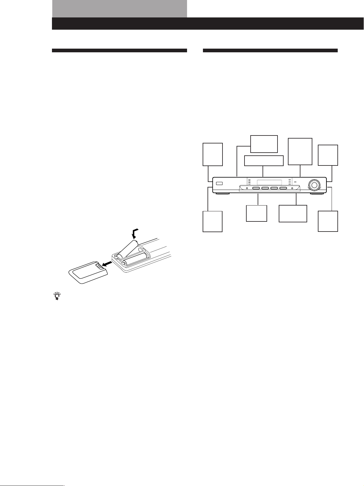
Inserting batteries into the remote
Insert two size AA (R6) batteries with the + and – on
the battery compartment. When using the remote,
point it at the remote sensor g on the amplifier.
Hookup Overview
The amplifier allows you to connect and control the
following video components. Follow the hookup
procedures for the components that you want to
connect to the amplifier on the pages specified. To
learn the locations and names of each jack, see “Rear
Panel Descriptions” on page 22.
Video Component
Speaker System
Hookups (6)
Front
speaker
(L)
Rear
speaker
(L)
Hookups (5)
TV
VCR
Center
speaker
DVD
player/
AC-3
decoder
Active
subwoofer
Front
speaker
(R)
Rear
speaker
(R)
]
}
}
]
When to replace batteries
Under normal use, the batteries should last for about 6
months. When the remote no longer operates the
amplifier, replace both batteries with new ones.
Notes
• Do not leave the remote in an extremely hot or humid
place.
• Do not use a new battery with an old one.
• Do not expose the remote sensor to direct sunlight or
lighting apparatuses. Doing so may cause a malfunction.
• If you don’t use the remote for an extended period of time,
remove the batteries to avoid possible damage from
battery leakage and corrosion.
Before you get started
• Turn off the power to all components before making
any connections.
• Do not connect the mains lead until all of the
connections are completed.
• Be sure to make connections firmly to avoid hum
and noise.
• When connecting an audio cable, be sure to match
the colour-coded pins to the appropriate jacks on the
components: White (left, audio) to White; and Red
(right, audio) to Red.
4
Page 5
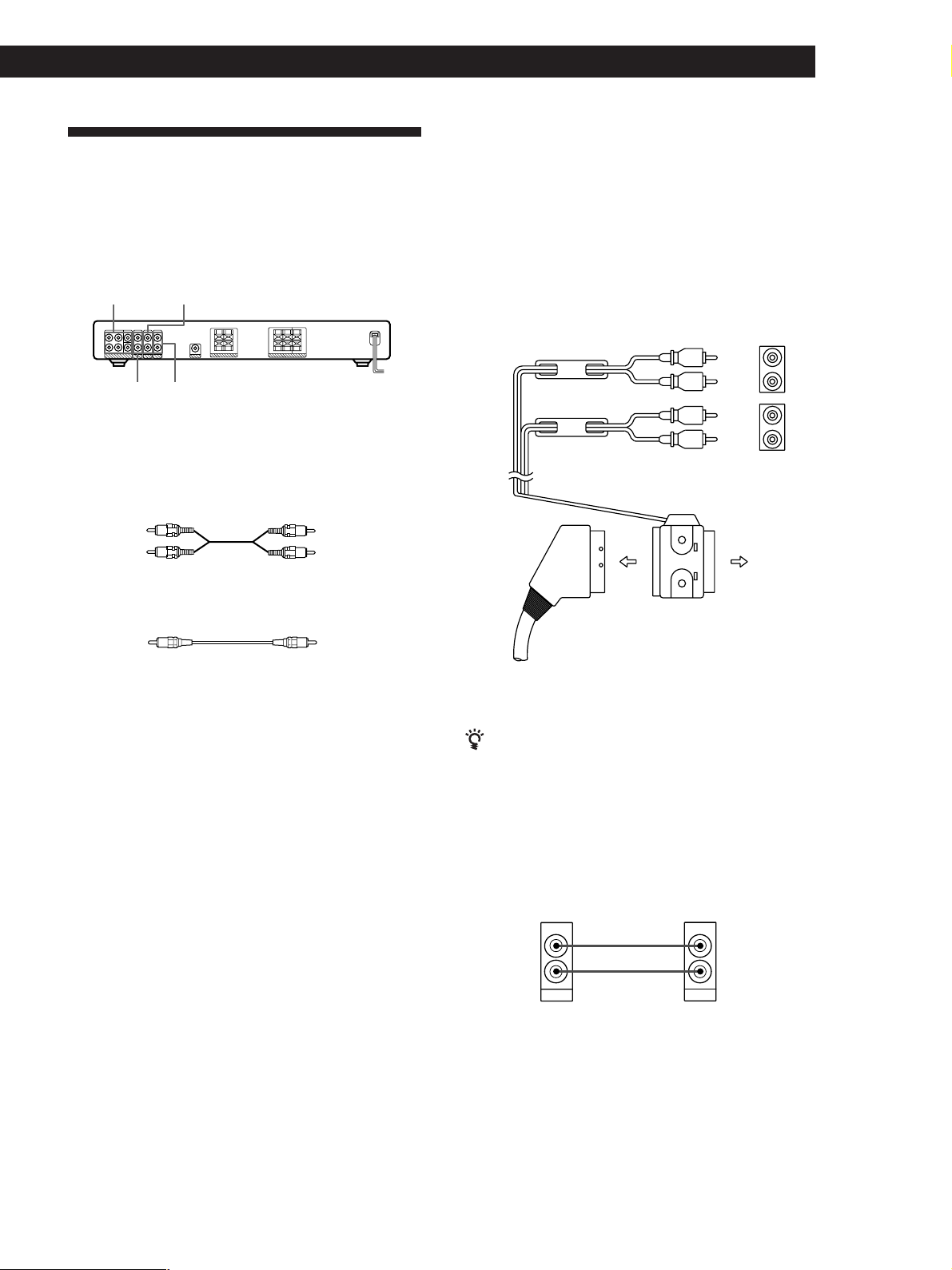
Video Component Hookups
Getting Started
Hookups
The arrow l indicates signal flow.
Overview
This section describes how to connect video
components to the amplifier. For specific locations of
the jacks, see the illustration below.
5.1CH/DVD TV
DVD 2CH
What cords will I need?
• Scart adaptor (supplied)
• Euro AV cable (not supplied) (1 for each TV or VCR)
• Audio cords (not supplied) (1 for DVD player, 2 for AC-3
decoder’s FRONT and REAR jacks)
Red (R)
• Monaural audio cords (not supplied)
(2 for AC-3 decoder’s CENTER and WOOFER jacks)
VIDEO
White (L)White (L)
Red (R)
BlackBlack
TV/VCR
You can listen to the sound from VCR or TV by
connecting the audio signal from VCR or TV to the
amplifier.
Amplifier
VIDEO AUDIO IN
To VTR audio input
To TV audio input
Euro AV cable (not
supplied)
n
To TV
ç
ç
Scart adaptor
(supplied)
White
(L)
Red
(R)
White
(L)
Red
(R)
TV
VTRTV
L
R
L
R
If you have another component, such as a second VCR
or LD player, connect it to the DVD 2CH jacks.
DVD Player
If your DVD player does not have 5.1 CH output,
connect the audio output jacks of the DVD player to the
DVD 2CH jacks of the amplifier.
Amplifier
DVD 2CH
AUDIO IN
LL
DVD 2CH
L
DVD player
AUDIO OUT
AUDIO OUT
RR
(continued)
5
Page 6
Getting Started
DVD player with AC-3 decoder
If you have a Dolby Digital (AC-3) decoder or a DVD
player with a built-in AC-3 decoder, you can play
decoded Dolby Digital (AC-3) soundtracks through the
speakers connected to the amplifier. Connect the
decoder as follows:
Amplifier
5.1 CH/DVD
FRONT
L L
L
CENTER
REAR
L
WOOFER
5.1CH / DVD
L
L
Dolby Digital AC-3
decoder (etc.)
PRE OUT
REAR
CENTER
WOOFER
5.1CH OUTPUT
FRONT
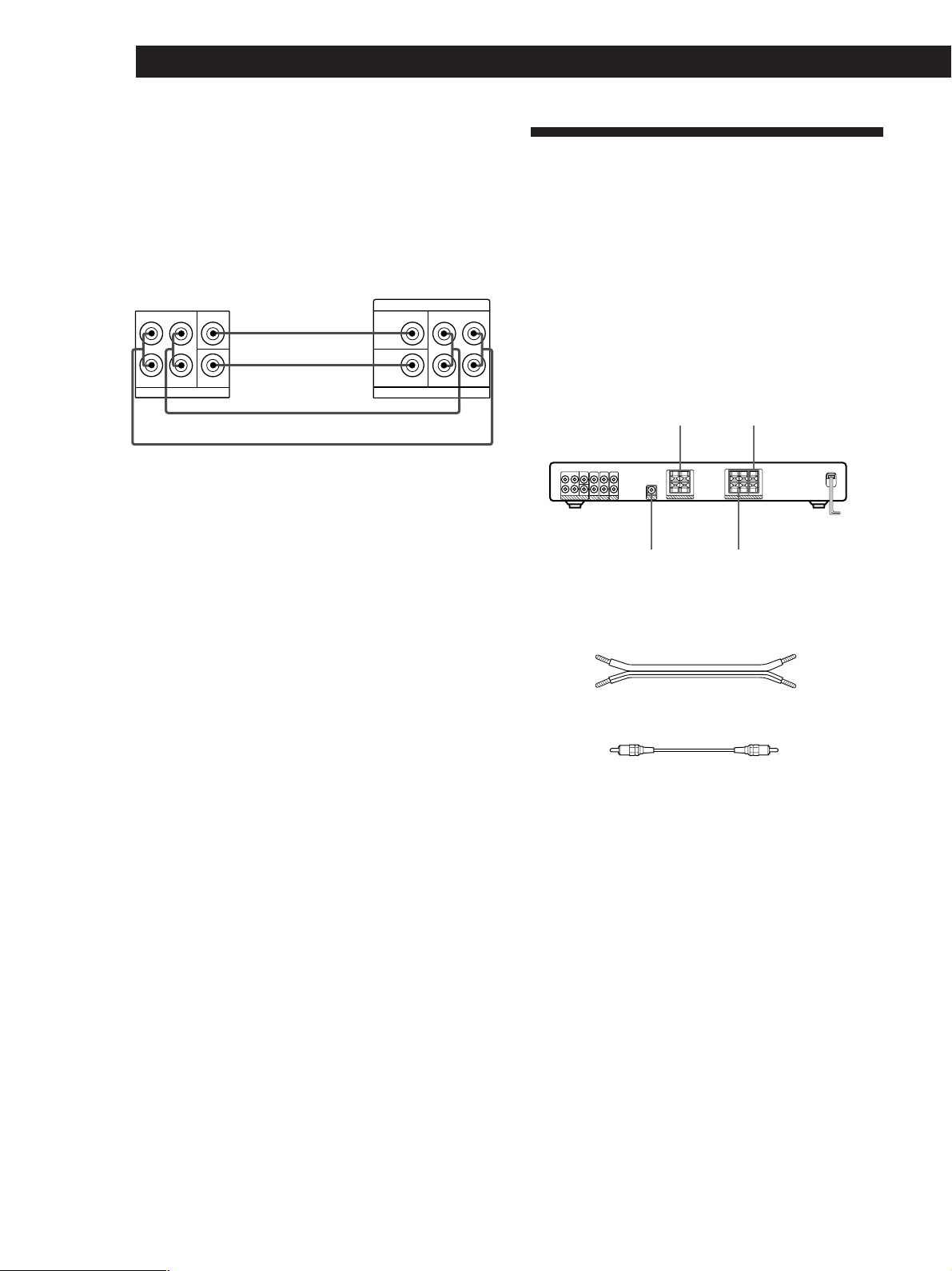
Speaker System Hookups and
Setups
Overview
This section describes how to connect the supplied
speakers (SS-MS215) to the amplifier. Connecting the
active woofer (SA-WMS215) will increase bass
response.
For specific locations of the terminals, see the
RR
illustration below.
FRONT
SPEAKERS
CENTER
SPEAKER
WOOFER
(AUDIO OUT)
REAR
SPEAKERS
What cords will I need?
• Speaker connecting cord (supplied) (1 for each speaker)
(+)(+)
(–)
• Monaural connecting cord (supplied)
Black
(–)
Black
6
Page 7
Getting Started
R
EAR
+
–
RL
RL
REAR
+
–
R
L
RL
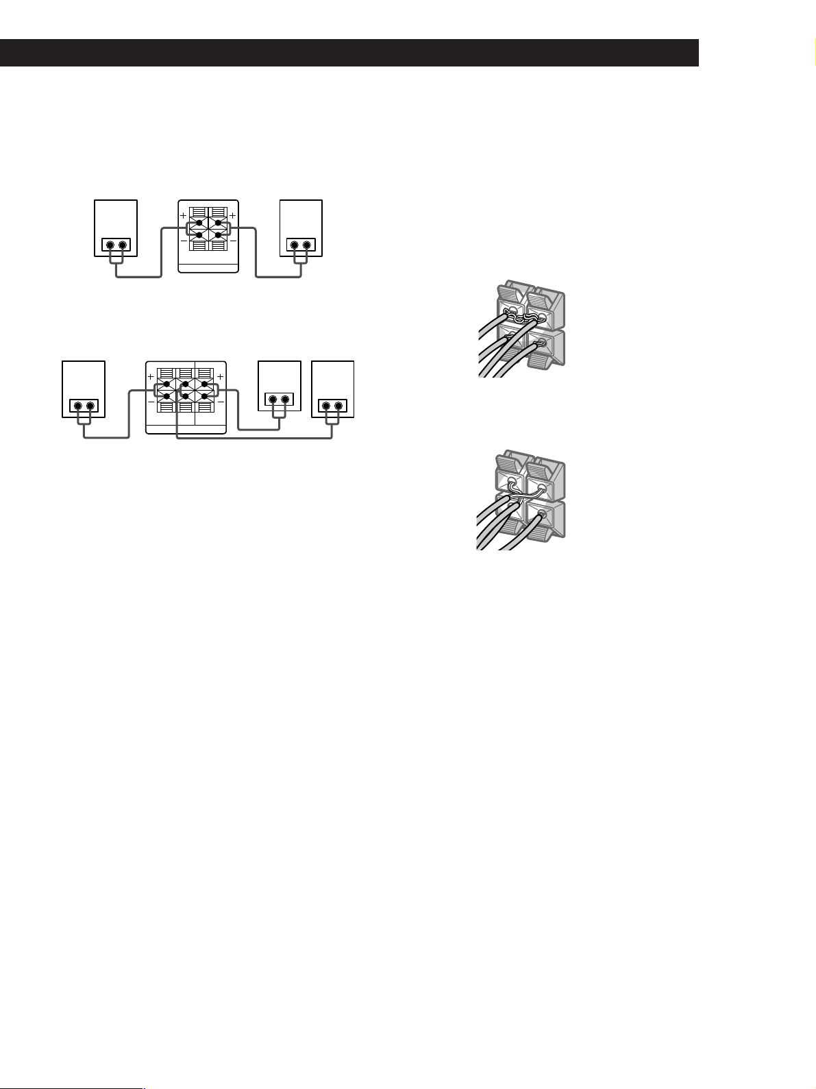
Hookups
Front speakers (SS-MS215)
Front speaker
(R)
Amplifier
R-FRONT-L
SPEAKERS
Rear and center speakers (SS-MS215)
Rear speaker
(R)
Amplifier
R-REAR-L CENTER
SPEAKERS
Center speaker
Notes
• Be sure to match the speaker cord to the appropriate
terminal on the components: + to + and – to –. If the cords
are reversed, the sound will be distorted and will lack
bass.
• Make sure all connections are firm. Contact between bare
speaker wires at the speaker terminals may cause a shortcircuit.
Front speaker
(L)
Rear speaker
(L)
To avoid short-circuiting the speakers
Short-circuiting of the speakers may damage the
amplifier. To prevent this, make sure to take the
following precautions when connecting the speakers.
Make sure the stripped ends of each speaker cord does
not touch another speaker terminal or the stripped end
of another speaker cord.
Examples of poor conditions of the speaker cord:
Stripped speaker cord is touching another speaker
terminal.
Stripped cords are touching each other due to excessive
removal of insulation.
After connecting all the components, speakers, and AC
power cord, output a test tone to check that all the
speakers are connected correctly. For details on
outputting a test tone, refer to “Adjusting the speaker
volume” on page 17.
If you have connected rear speakers, be sure to press
the 5.1 CH/DVD button on the amplifier before
outputting a test tone so that the tone is output
individually from the left and right rear speakers.
If no sound is heard from a speaker while outputting a
test tone or a test tone is output from a speaker other
than the one whose name is currently displayed on the
amplifier, the speaker may be short-circuited. If this
happens, check the speaker connection again.
7
Page 8

Getting Started
Active subwoofer (SA-WMS215)
Active subwoofer
Amplifier
AUDIO OUT
WOOFER
INPUT
Caution
• The speaker unit of the active subwoofer is located at the
bottom of the active subwoofer.
• Avoid contact with the speaker unit as it is without a
cover.
• Place the active subwoofer on a flat surface to ensure there
is no obstruction to the speaker unit.
Positioning the speakers
Location of each speaker
Center
Subwoofer
Front
(Left)
Rear
(Left)
Each speaker should face the listening position. Better
surround effect will result if all speakers are set at the
same distance from the listening position.
Place the front speakers at a suitable distance to the left
and right of the television.
Place the subwoofer on either side of the television.
Place the center speaker on the top-center of the TV set.
The placement of rear speakers greatly depends on the
configuration of the room. The rear speakers may be
placed on both sides of the listening position A or
behind the listening position B.
Front
(Right)
Rear
(Right)
Setting the speakers
To prevent speaker vibration or movement while
listening, attach the supplied foot pads to the bottom
four corners of the center speaker, front speakers, and
rear speakers.
Front/Center/Rear
speakers
Foot pads
8
Page 9

Setting the center speaker
Set the center speaker firmly on top of the TV set,
making sure it is completely level.
Getting Started
AC Hookups
Foot pads
Setting other speakers
For greater flexibility in the positioning of the speakers,
use the optional WS-FV10, WS-TV10, or WS-WV10
speaker stand (available only in certain countries).
WS-FV10 WS-TV10
Note
You do not need to attach the foot pads if you are using the
speaker stand.
WS-WV10
(for rear speakers)
Connecting the mains lead
Connect the mains lead from this amplifier, active
subwoofer and from your video components to a wall
outlet.
Amplifier
/
to a wall outlet
Active subwoofer
/
to a wall outlet
Tip
The height of the front speakers should be adjusted to about
the center of the TV screen.
9
Page 10

Getting Started
Before You Use Y our Amplifier
Before you use your amplifier for the first time or when
you want to clear the amplifier’s memory, do the
procedure below:
?/1 (power)
1 Turn off the amplifier.
2 Press ?/1 (power) for more than 4 seconds.
“INITIAL” appears in the display and the items
including the following are reset or cleared:
• All sound field parameters are reset to their
factory settings.
• The fan control setup is reset to FAN ON.
Note
If you are using a Sony DVD player together with this home
theater system, set your DVD player to the following
configuration:
Speakers
Front
Center
Rear
Subwoofer
If you are using a non Sony DVD player, refer to the
operating instructions supplied with the DVD player for
speaker setup.
Settings
SMALL
SMALL
SMALL
YES
10
Page 11

Selecting a Component
To listen to a connected component, first select the
function on the amplifier or with the remote.
Before you begin, make sure you have:
• Connected all components securely and correctly as
indicated on pages 5 to 9.
1/u (power)
MASTER VOLUME
Amplifier OperationsAmplifier Operations
Watching video programmes
To take full advantage of the amplifier’s surround
sound effects, like Dolby Surround, turn off the
speakers on your TV before you start. This also lets you
use the amplifier’s remote to control the sound.
To watch TV programmes, do the following:
1 Turn on your TV.
2 Turn on the amplifier and press TV.
To watch videos or DVDs, do as follows:
Function buttons
1 Press 1/u (power) to turn on the amplifier.
2 Turn MASTER VOLUME to VOL MIN (indicated
on the display) to avoid damaging your speakers.
3 Press a function button to select the component
you want to use:
To watch
Video tapes
TV programmes
Digital versatile disc
(DVD)
DVD through
AC-3 decoder
To operate with the remote
Refer to “Using the remote” on page 12 for details.
Press
VIDEO
TV
DVD 2CH
5.1 CH/DVD
TV input mode
VIDEO
VIDEO
VIDEO
VIDEO
4 Turn on the component, the VCR for example,
and start playback.
1 Turn on your TV and set the TV’s input to match
the video component you watch.
2 Turn on the amplifier and press the function
button (VIDEO, DVD 2CH or 5.1 CH/DVD) to
select the component you want to use.
3 Turn on the video component and start
playback.
5 Turn MASTER VOLUME to adjust the volume.
To
Mute the sound
Do this
Press MUTING on the remote.
Press again to restore the sound.
(continued)
11
Page 12

Amplifier Operations
Using the remote
The remote lets you operate the amplifier and the Sony
components that are connected to it.
AV ?/1
?/1
SYSTEM
CONTROL/
FUNCTION
1 Press one of the SYSTEM CONTROL/
FUNCTION buttons to select the component you
want to use.
The amplifier and the selected component turn
on.
The SYSTEM CONTROL/FUNCTION buttons on
the remote are factory-set as follows:
To play
TV programmes
VHS Tapes
(VTR-3 mode)
DVD player
(for 2-ch playback)
DVD player/
AC-3 decoder
Press
TV
VIDEO
DVD
5.1 CH
To turn off the components
Press AV ?/1 and ?/1 simultaneously. This will also turn
off the Sony video/audio components at the same time. If
the components do not turn off, press the power switch on
the components.
If you use a Sony TV
• The TV turns on automatically and switches to the
appropriate video input when you press VIDEO. If
the TV does not switch to the appropriate input
automatically, press TV/VIDEO on the remote.
• When you use the TV only, turn on the TV using the
TV’s remote.
If you want to change the factory setting of a button
See “Changing the Factory Setting of a FUNCTION
Button” on page 13.
If the component does not turn on
Press the power switch on the component.
2 Start playing.
Refer to “Remote Button Descriptions” on page 21
for details.
12
Page 13

Changing the Factory Setting
Amplifier Operations
of a FUNCTION Button
If the factory settings of the SYSTEM CONTROL/
FUNCTION buttons (“Using the remote” on page 12)
don’t match your system components, you can change
them. The following table shows the possibility of
alternate function assignment for each button.
Button Possible assignment
VIDEO VTR 1, VTR 2, VTR 3
DVD DVD, LDP, CD
* Initial setting of VIDEO is VTR 3.
* Sony VCRs are operated with a VTR 1, 2, or 3 setting that
corresponds to Beta, 8mm, and VHS, respectively.
Resetting key table for function key VIDEO
VTR 1 CURSOR UP
VTR 2 ENTER/EXECUTE
VTR 3 CURSOR DOWN
Resetting key table for function key DVD
DVD EXIT/RETURN
LD DISPLAY
CD CURSOR RIGHT
SYSTEM
CONTROL/
FUNCTION
MENU
control keys
For example, if you connect a Sony LD player to the
DVD jacks, you can assign the DVD button to set the
remote to control the LD player.
1 Hold down the SYSTEM CONTROL/FUNCTION
button whose function you want to change (DVD,
for example).
2 Press the corresponding button of the component
you want to assign to the SYSTEM CONTROL/
FUNCTION button (DISPLAY, LD player, for
example).
Now you can use the DVD button to control your
Sony LD player.
To reset a button to its factory setting
Repeat the above procedure.
To reset all the function buttons to their factory setting
Press ?/1, AV ?/1 and MASTER VOL – at the same time.
13
Page 14

Amplifier Operations
Using the Sleep Timer
You can set the amplifier to turn off automatically at a
time you specify.
SLEEP
Press SLEEP on the remote while the power is on.
Each time you press SLEEP, the time changes as shown
below.
t 2:00:00 t 1:30:00 t 1:00:00 t 0:30:00 t OFF
The display dims after you specify the time.
You can check the time remaining before the
amplifier turns off
Press SLEEP on the remote. The remaining time appears
in the display.
14
Page 15

Choosing a Sound Field
You can take advantage of surround sound simply by
selecting one of the three pre-programmed sound field
according to the type of programme you wish to play.
Sound field indicators
SOUND FIELD
Using Surround SoundUsing Surround Sound
You can find Dolby Surround-encoded software by
looking at the packaging
However, some videos and laser discs may use Dolby
Surround sound even if it’s not indicated on the
package.
Note
Surround sound is turned off when you select the
5.1 CH/DVD.
Adjusting the effect level
(for C. STUDIO and SIMULATED only)
You can make the surround sound more prominent by
increasing the EFFECT level. This control lets you
adjust the “presence” of the surround effect in six steps
(1-6).
SOUND FIELD
ON/OFF
SOUND FIELD
MODE
EFFECT/
DELAY –/+
1 Press SOUND FIELD or SOUND FIELD ON/OFF
on the remote to turn on the sound field.
One of the SOUND FIELD indicators lights up in
the display.
2 Press SOUND FIELD or SOUND FIELD MODE
on the remote repeatedly until the indicator for
the sound field you want lights up.
Select the appropriate sound field as follows:
Select
PRO LOGIC*
C. STUDIO
(Cinema Studio)
SIMULATED
To
Decodes programmes processed
with Dolby Pro Logic Surround.
Reproduces the sound characteristics
of a movie theater. Good for
watching standard movies.
Create a simulated surround sound
from monaural sources such as old
movies or TV programmes.
1 Start playing a programme source.
2 Use EFFECT/DELAY (–/+) on the remote to
select the level you prefer. The effect level is
indicated on the display.
Note
Changing the effect level may not produce major variations
in the surround effect when used with certain playback
sources.
* “DOLBY PL” appears on the display.
To turn off sound field
Press SOUND FIELD ON/OFF on the remote or press
SOUND FIELD repeatedly until “SF OFF” appears on the
display.
15
Page 16

Using Surround Sound
Getting the Most Out of Dolby
Pro Logic Surround Sound
To obtain the best possible Dolby Pro Logic Surround
sound, first select the center mode according to the
speaker system you have. Then, adjust the volume of
each speaker.
Note that you must connect the rear speakers and/or
one center speaker to do the following adjustments.
Selecting the center mode
The amplifier offers you four center modes: Phantom,
Wide, Normal and 3 Stereo. Each mode is designed for
a different speaker configuration.
1 Press SOUND FIELD repeatedly to select the PRO
LOGIC sound field.
2 Press CENTER MODE repeatedly until the
indicator for the center mode you want lights in
the display.
Select the center mode as follows:
Center mode
indicators
SOUND FIELD
ON/OFF
TEST TONE
REAR
LEVEL +/–
Display
Sound field
indicators
SOUND FIELDCENTER MODE
SOUND FIELD
MODE
EFFECT/
DELAY –/+
CENTER
LEVEL +/–
If you have
Front and rear
speakers, no
center speaker
Front and rear
speakers, and
a large center
speaker
Front and rear
speakers, and
a small center
speaker
Front and center
speakers, no rear
speaker
Select
PHANTOM
WIDE
NORMAL
3 STEREO
(3 Channel Logic)
So that
The sound of the
center channel is
output from the front
speakers.
The center channel
fully reproduces the
entire audio spectrum
The bass sound of the
center channel is
output from the front
speakers.
The sound of the rear
channel is output
from the front
speakers.
Notes
• To match the speaker system that is packed together with
this amplifier, we recommend that you set the center
mode to NORMAL or WIDE and turn on the subwoofer.
• If you are using a different speaker system, select the
mode that best suits your speaker system’s configuration.
16
Page 17

Using Surround Sound
Adjusting the speaker volume
The test tone feature lets you set the volume of your
speakers to the same level.
Using the controls on the remote lets you test the
speaker connection and adjust the volume level from
your listening position.
1 Press SOUND FIELD repeatedly to select
“DOLBY PL” and set the center mode to
NORMAL.
2 Press TEST TONE on the remote.
You will hear the test tone from each speaker
sequentially.
3 Adjust the volume level so that the test tone from
each speaker is at the same level from your
listening position.
• To adjust the level of center speaker, press
CENTER LEVEL + or – on the remote.
• To adjust the level of rear speakers, press
REAR LEVEL + or – on the remote.
The center and rear levels are indicated on the
display.
Adjusting the delay time
You can make the surround sound more effective by
delaying the output from the rear speakers (delay
time). You can select from three delay times, S (15 mS),
M (20 mS), and L (30 mS). For example, if you’ve
placed the rear speakers in a large room or apart from
your listening position, set the delay time shorter.
1 Start playing a programme source encoded with
Dolby Surround sound.
2 Press SOUND FIELD repeatedly to select
“DOLBY PL” and set the center mode to
NORMAL.
3 Press EFFECT/DELAY (–/+) on the remote
repeatedly to choose the delay time parameter.
The current delay time appears in the display,
such as “DELAY S,” “DELAY M” or “DELAY L.”
Note
If the AC power cord is disconnected for about one week,
amplifier’s surround parameter will be reset to the factory
settings.
4 Press TEST TONE on the remote to turn off the
test tone.
You can adjust all speakers at one time
Adjust MASTER VOL on the remote or MASTER
VOLUME on the amplifier.
You can increase the output level of the rear
speakers
The adjustment range of the rear speakers is preset from
–10 to +6, but you can shift the range up 3 levels (–7 to
+9). Hold down SOUND FIELD on the amplifier while
turning on the power until “NORMAL” appears on the
display.
The values for the rear level remain fixed at –10 to +6 in
the display, but you will be able to hear the difference in
the actual output level.
To reset the rear level adjustment range, repeat this
procedure to display “GAIN LOW”.
Note
During 5.1 CH/DVD mode, CENTER LEVEL and REAR
LEVEL cannot be adjusted.
Adjusting the subwoofer
Slight adjustments to the system can enhance your
sound enjoyment.
LEVEL
POWER
MIN MAX
LEVEL
1 Rotate LEVEL to adjust the volume.
Set the volume level to best suit your preference
according to the programme source.
Note
To enjoy high-quality sound, do not turn the subwoofer
volume too high.
17
Page 18

Additional InformationAdditional Information
Troubleshooting
If you experience any of the following difficulties while
using the home theater system, use this
troubleshooting guide to help you remedy the
problem. Should any problem persist, consult your
nearest Sony dealer.
There’s no sound or only a very low-level sound is heard.
, Check that the speakers and components are
connected securely.
, Press MUTING on the remote if the MUTING
indicator turns on.
, Make sure you select the correct component
on the amplifier.
, Check whether or not you used the
appropriate AV cables.
, The protective device on the amplifier has
been activated because of a short circuit.
(“PROTECT” flashes.) Turn off the amplifier,
eliminate the short-circuit problem and turn
on the power again.
The left and right sounds are unbalanced or reversed.
, Check that the speakers and components are
connected correctly and securely.
Severe hum or noise is heard.
, Check that the speakers and components are
connected securely.
, Check that the connecting cords are away
from a transformer or motor, and at least 3
meters (10 feet) away from a TV set or
fluorescent light.
, Place your TV away from the audio
components.
, The plugs and jacks are dirty. Wipe them
with a cloth slightly moistened with alcohol.
No sound is heard from the center speaker.
, Select the appropriate center mode (see page
16).
, Adjust the speaker volume appropriately (see
page 17).
No sound or only a very low-level sound is heard from
the subwoofer.
, Make sure you turn on the subwoofer.
, Make sure the connection is made correctly.
The sound has suddenly stopped.
, Make sure all the connections have been
correctly made. Contact between bare speaker
wires at the speaker terminals may cause a
short-circuit.
Surround effect cannot be obtained.
, Make sure you turn on the sound field
function.
No picture or an unclear picture is seen on the TV screen.
, Select the appropriate input on your TV.
, Select the appropriate component on the
amplifier.
The remote does not function.
, Point the remote at the remote sensor g on
the amplifier.
, Remove the obstacles in the path of the
remote and the amplifier.
, Replace both batteries in the remote with new
ones if they are weak.
, Make sure you select the correct function on
the remote.
18
No sound or only a very low-level sound is heard from
the rear speakers.
, Select the appropriate center mode (see page
16).
, Adjust the speaker volume appropriately (see
page 17).
, Make sure you turn on the sound field
surround mode function.
Note
The Dolby Surround effect is dependent on the software
and center mode being used.
Page 19

Additional Information
Specifications
Amplifier section
Power output
Rated Power
Output at Stereo
mode
Reference
Power Output
Frequency
response
Inputs
TV,
VIDEO,
DVD 2CH,
5.1 CH/
DVD
Outputs
Muting
General
Power
requirements
(DIN 1 kHz, 8 ohms)
25 W + 25 W
(DIN 1 kHz, 8 ohms)
Front: 25 W / ch
Center: 25 W
Rear: 25 W / ch
TV, VIDEO, DVD 2CH,
5.1 CH/DVD :
10 Hz - 50 kHz +0.5/–2 dB
Sensitivity
250 mV
Impedance
50
kilohms
WOOFER:
Voltage: 1 V
Impedance: 1 kilohms
Full mute
220 - 230 V AC, 50/60 Hz
S/N
(weighting
network,
input level)
85 dB*
(A, 250 mV)
*78 IHF
Speaker section
SS-MS215 Front, center and rear
speakers
Speaker system
Speaker units
Enclosure type
Rated
impedance
Power handling
capacity
(Maximum input
power)
Sensitivity level
Frequency range
Dimensions
(w/h/d)
Mass
Full range, magnetically
shielded
5 cm cone type
Bass reflex
8 ohms
60 watts
84 dB (1 W, 1m)
150 Hz - 20, 000 Hz
Approx. 76 x 100 x 86 mm
including front grille
Approx. 425 g
SA-WMS215 Subwoofer
System
Speaker system
Speaker unit
Enclosure type
Continuous RMS
power output
(8 ohms, 20 250 Hz)
Reproduction
frequency range
High frequency
cut-off
frequency
Active subwoofer,
magnetically shielded
Woofer: 16 cm cone type
Acoustically Loaded Bass
Reflex
50 W
32 Hz - 250 Hz
250 Hz
Input
LINE IN (input pin jack)
General
Power
requirements
Power
consumptions
Dimensions
(w/h/d)
Mass
Supplied
accessories
Design and specifications are subject to
change without notice.
220 - 230 V AC, 50/60 Hz
45 W
Approx. 240 x 285 x 355
mm including front
panel
Approx. 8 kg
See page 4.
Power
consumption
Dimensions
Mass (Approx.)
115 W
430 x 274 x 64.5 mm
4.6 kg
Specifications indicated are measured at
230 VAC, 50Hz.
19
Page 20

Additional Information
Glossary
Center mode
Setting of speakers to enhance Dolby Pro
Logic Surround mode. To obtain the best
possible surround sound, select one of the
following four center modes according to
your speaker system.
• NORMAL mode
Select NORMAL mode if you have front
and rear speakers and a small center
speaker. Since a small speaker cannot
produce enough bass, the bass sound of
the center channel is output from the front
speakers.
Front
speaker (L)
speaker (L)
Center
speaker
Rear
• WIDE mode
Select WIDE mode if you have front and
rear speakers and a large center speaker.
With the WIDE mode, you can take full
advantage of Dolby Surround sound.
Front
speaker (L)
Center
speaker
Rear
speaker (L)
• PHANTOM mode
Select PHANTOM mode if you have front
and rear speakers but no center speaker.
The sound of the center channel is output
from the front speakers.
Front
speaker (L)
Front
speaker (R)
Rear
speaker (R)
Front
speaker (R)
Rear
speaker (R)
Front
speaker (R)
• 3 STEREO (3 CH LOGIC)
Select 3 STEREO mode if you have front
and center speakers but no rear speaker.
The sound of the rear channel is output
from the front speakers to let you
experience some of the surround sound
without using rear speakers.
Center
Front
speaker (L)
speaker
Front
speaker (R)
Dolby Pro Logic Surround
Decoding system of Dolby Surround sound
standardized in TV programmes and movies.
Compared with the former Dolby Surround
system, Dolby Pro Logic Surround improves
sound image by using four separate channels:
off-screen audio effects, on-screen dialog, leftto-right panning, and music. These channels
manipulate the sound to be heard and
enhance the action as it happens on the
screen. To take advantage of Dolby Pro Logic,
you should have at least one pair of rear
speakers and/or one center speaker. You also
need to select the appropriate center mode to
enjoy a full effect.
Dolby Digital (AC-3)
This surround format is more advanced than
Dolby Pro Logic Surround. In this format, the
rear speakers output stereo sound with an
expanded frequency range and a subwoofer
channel for deep bass is independantly
provided. This format is also called “5.1”
because the subwoofer channel is counted as
0.1 channel (since it functions only when a
deep bass effect is needed.)
All six channels in this format are recorded
separately to realize superior channel
separation. Furthermore, since all the signals
are processed digitally, less signal
degradation occurs. The name “AC-3” comes
from the fact that it is the third audio coding
method to be developed by the Dolby
Laboratories Licensing Corporation.
5.1 CH/DVD jacks
These jacks are used to input decoded Dolby
Digital (AC-3) audio signals, allowing you to
enjoy 5.1 channel surround sound. Use these
jacks to connect a Dolby Digital (AC-3)
decoder or a DVD player with a built-in AC-3
decoder.
• Types of sound
Early reflections
Direct sound
Reverberation
• Transition of sound from rear speakers
Direct sound
Level
Early reflection time
Early
reflections
Reverberation
Time
Test tone
Signal given out by the amplifier for
adjusting the speaker volume. The test tone
will come out as follows:
• In a system with a center speaker
(NORMAL/WIDE/3 STEREO modes)
The test tone is output from the front L
(left), center, front R (right), and rear
speakers in succession.
Front (L)
3 STEREO
Rear (L, R)
NORMAL/WIDE
Front (R)
Center
• In a system without a center speaker
(PHANTOM mode)
The test tone is output from the front and
the rear speakers alternately.
Front (L, R)
PHANTOM
Rear (L, R)
20
Rear
speaker (L)
Rear
speaker (R)
Surround sound
Sound that consists of three elements: direct
sound, early reflected sound (early
reflections) and reverberative sound
(reverberation). The acoustics where you hear
the sound affect the way these three sound
elements are heard. These sound elements are
combined in such a way that you can actually
feel the size and the type of a concert hall.
Page 21

Additional Information
Remote Button Description
For buttons not described on previous pages and
buttons with names different from the buttons on the
main unit.
Remote
Button
m/M
./>
X
N
x
AV/
?/1
ENTER/
EXECUTE
ANT TV/
VTR
MENU
TITLE
EXIT/
RETURN
DISPLAY
>
>
>
<
Operates
VCR/DVD/
CD/LDP
DVD/CD/
LDP
VCR/DVD/
CD/LDP
VCR/DVD/
CD/LDP
VCR/DVD/
CD/LDP
TV/VCR/
DVD/LDP
TV/VCR/
DVD
VCR
TV/VCR/
DVD
DVD
TV/DVD
TV/DVD/
LDP
TV/VCR/
DVD
TV/VCR/
DVD
TV/VCR/
DVD
TV/VCR/
DVD
Function
Fast forwards or rewinds.
Skips tracks.
Pauses play.
Starts play.
Stops play.
Turns on or off the power.
Confirm setting.
Selects output signal from
the antenna terminal: TV
signal or VCR programme.
Display menu.
Display current DVD title.
Exit from menu mode or
return to previous screen.
Selects information
displayed on the TV
screen.
To increase a value or
move the cursor upwards
on the menu screen such
as VIDEO CONTROL/
AUDIO CONTROL/SET
UP/LANGUAGE/DEMO
To decrease a value or
move the cursor
downwards on the menu
screen such as VIDEO
CONTROL/AUDIO
CONTROL/SET UP/
LANGUAGE/DEMO
To move the cursor to the
right side of the menu
screen.
To move the cursor to the
left side of the menu
screen.
Remote
Operates
Function
Button
VTR CH
+/–
TV CH
+/–
TV VOL
+/–
* The MENU control keys may not operate on certain Sony
TVs.
VCR
TV
TV
VCR channel selection.
TV channel selection.
To adjust the TV volume.
21
Page 22

Additional InformationIndex
Index
A, B
Adjusting
speaker volume 17
volume 11
C
Center mode 16, 20
NORMAL mode 16, 20
PHANTOM mode 16, 20
3 STEREO mode 16, 20
WIDE mode 16, 20
Connecting. See Hookups
D, E, F, G
Dolby Digital (AC-3) 20
Dolby Pro Logic
Surround 20
getting the most out of 16
Dolby Surround sound 15, 20
center mode 16, 20
H, I, J, K, L, M
Hookups
mains lead 9
overview 4
speakers 7
video component 5
N, O
NORMAL mode 16, 20
P, Q
PHANTOM mode 16, 20
Programme source
selecting 11
R
Rear panel 5, 6, 9, 22
Remote buttons 12, 13, 21
S
Selecting a programme source
11
using the remote 12
Sleep timer 14
Sound field 13, 14
Speakers
connection 7
impedance 19
placement 8
T
Test tone 16, 20
3 STEREO mode 16, 20
Troubleshooting 18
U
Unpacking 4
V
Video Component Hookups 5
W, X, Y, Z
Watching video programmes
11
WIDE mode 16, 20
Rear Panel Descriptions
15 7
3
1 5.1 CH/DVD
2 DVD 2CH
3 TV
4 VIDEO
5 WOOFER
6 FRONT SPEAKERS
9
8642
7 REAR SPEAKERS
8 CENTER SPEAKER
9 Mains lead
22
Page 23

Sony Corporation Printed in Malaysia
 Loading...