

Sony HT-DDW970, HT-DDW1000 Operating Instructions Manual
2-549-734-91(1)
Home Theatre
System
Operating Instructions
HT-DDW970
©2005 Sony Corporation
WARNING
To prevent fire or shock hazard, do not
expose the unit to rain or moisture.
To prevent fire, do not cover the ventilation of the
apparatus with newspapers, table-cloths, curtains, etc.
And don’t place lighted candles on the apparatus.
To prevent fire or shock hazard, do not place objects
filled with liquids, such as vases, on the apparatus.
Do not install the appliance in a confined space,
such as a bookcase or built-in cabinet.
Don’t throw away batteries with
general house waste; dispose of
them correctly as chemical waste.
For customers in Australia
ENERGY STAR® is a U.S. registered
mark. As an E
Sony Corporation has determined that
this product meets the E
guidelines for energy efficiency.
NERGY STAR
®
partner,
NERGY STAR
About This Manual
• The instructions in this manual is for model
HT-DDW970. Check your receiver’s model number
by looking at the lower right corner of the front
panel.
• The instructions in this manual describe the controls
on the receiver. You can also use the controls on the
supplied remote if they have the same or similar
names as those on the receiver. For details on the use
of your remote, see pages 41–48.
The HT-DDW970 consists of:
• Receiver STR-K970P
• Speaker system
– Front speaker (left) SS-MSP87L
– Front speaker (right) SS-MSP87R
– Center speaker SS-CNP87
– Surround speaker (left) SS-MSP87SL
– Surround speaker (right) SS-MSP87SR
– Surround back speaker SS-MSP87SB
– Sub woofer SA-WMSP87
®
This receiver incorporates Dolby* Digital and Pro
Logic Surround and the DTS** Digital Surround
System.
* Manufactured under license from Dolby
Laboratories.
“Dolby”, “Pro Logic” and the double-D symbol are
trademarks of Dolby Laboratories.
** “DTS”, “DTS-ES”, “Neo:6” and “DTS 96/24” are
trademarks of Digital Theater Systems, Inc.
Note for the supplied remote
For RM-AAP001
The AUX and 12 buttons on the remote are not
available for receiver operation.
GB
2

Table of Contents
Getting Started
1: Check how to hookup your
components.......................................4
1a: Connecting components with
digital audio output jacks ...........6
1b: Connecting components with
multi channel output jacks.......... 9
1c: Connecting components with
only analog audio jacks ............11
2: Connecting the antennas ...................13
3: Connecting speakers .........................14
4: Connecting the AC power cord ........17
5: Setting up the speakers ..................... 18
6: Setting up the sub woofer .................20
7: Adjusting the speaker levels and
balance............................................20
— TEST TONE
Amplifier Operation
Selecting the component .......................21
Listening to multi channel sound..........22
— MULTI CH IN
Listening to FM/AM radio....................22
Presetting radio stations........................23
Changing the display.............................24
About the indications in the display......25
Enjoying Surround Sound
Using only the front speakers and sub
woofer.............................................27
— 2CH STEREO
Enjoying higher fidelity sound..............27
— AUTO FORMAT DIRECT
Selecting a sound field ..........................29
Selecting the surround back decoding
mode ...............................................31
— SURR BACK DECODING
Advanced Adjustments and
Settings
Reassigning the component video
input................................................ 33
— COMPONENT VIDEO
INPUT ASSIGN
Switching the audio input mode for
digital components ......................... 33
— INPUT MODE
Customizing sound fields ..................... 34
Adjusting the tone................................. 35
Advanced settings................................. 36
Other Operations
Naming preset stations and inputs........ 38
Using the Sleep Timer .......................... 38
Selecting the speaker system ................ 39
Recording.............................................. 39
Operations Using the Remote
RM-AAP001
Before you use your remote.................. 41
Remote button description.................... 41
Selecting the command mode of the
remote............................................. 45
Programming the remote ...................... 46
Additional Information
Precautions............................................ 49
Troubleshooting.................................... 50
Specifications........................................ 52
List of button locations and reference
pages............................................... 54
Index ..................................................... 55
GB
3

Getting Started
1: Check how to hookup your components
Steps 1a through 1c beginning on page 6 describe how to hook up your components to this receiver.
Before you begin, refer to “Connectable components” below for the pages which describe how to
connect each component.
After hooking up all your components, proceed to “2: Connecting the antennas” (page 13).
Connectable components
Component to be connected Page
DVD player
With digital audio output
With multi channel audio output
With analog audio output only
TV monitor
With component video input
With composite video input only 12
Satellite tuner
With digital audio output
With analog audio output only
Super Audio CD/CD player
With digital audio output
With multi channel audio output
With analog audio output only
MD/Tape deck
With analog audio output only
Multi channel decoder 9
VCR, camcorder, video game, etc. 12
a)
b)
c)
d)
a)
c)
a)
b)
c)
c)
6–7
9–10
6–7
7 or 10
6–7
6–7
8
9
11
11
a)
Model with a DIGITAL OPTICAL OUTPUT or DIGITAL COAXIAL OUTPUT jack, etc.
b)
Model with a MULTI CH OUTPUT jacks, etc. This connection is used to output the audio decoded by the
component’s internal multi channel decoder through this receiver.
c)
Model equipped only with AUDIO OUT L/R jacks, etc.
d)
Model with component video (Y, PB/CB/B-Y, PR/CR/R-Y) input jacks.
GB
4
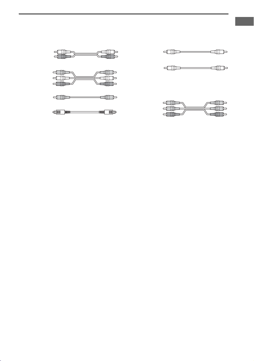
Required cords
The hookup diagrams on the subsequent pages assume the use of the following optional connection
cords (A to G) (not supplied unless indicated).
A Audio cord
White (L)
Red (R)
B Audio/video cord
Yellow (video)
White (L/audio)
Red (R/audio)
C Video cord
Yellow
D Optical digital cord
Notes
• Turn off the power to all components before making any connections.
• Be sure to make connections firmly to avoid hum and noise.
• When connecting an audio/video cord, be sure to match the color-coded pins to the appropriate jacks on the
components: yellow (video) to yellow; white (left, audio) to white; and red (right, audio) to red.
• When connecting optical digital cords, insert the cord plugs straight in until they click into place.
• Do not bend or tie optical digital cords.
E Coaxial digital cord (supplied)
Orange
F Monaural audio cord
Black
Tip
Audio cord A can be torn into two monaural audio
cords F.
G Component video cord
Green
Blue
Red
Getting Started
GB
5
.
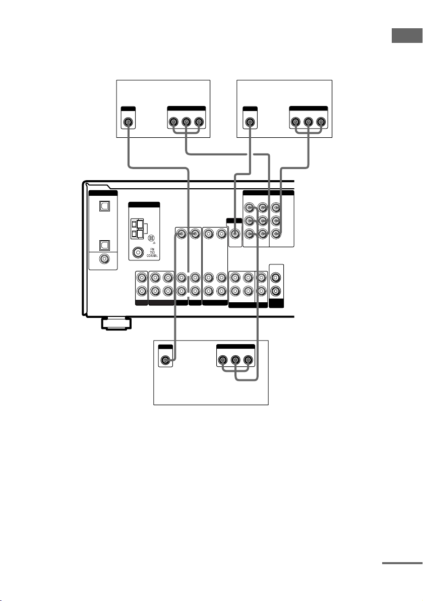
1a: Connecting components with digital audio output jacks
Hooking up a DVD player, TV monitor or satellite tuner
For details on the required cords (A–G), see page 5.
1 Connect the audio jacks.
DVD player
OUTPUT
AUDIO
OUT
OUTPUT
DIGITAL
COAXIAL
L
R
AE
MONITOR
FRONT
MULTI CH IN
COMPONENT VIDEO
ASSIGNABLE
VIDEO 2INMONITOR
DVD
IN
L
CENTER
R
SUB
SURROUND
WOOFER
OUT
AUDIO
OUT
SUB
WOOFER
Y
PB/C
B
/B–Y
P
R/CR
/R–Y
DIGITAL
OPTICAL
VIDEO 2
IN
SA-CD/
CD
IN
DVD
IN
COAXIAL
D
OUTPUT
DIGITAL
OPTICAL
ANTENNA
L
R
SA-CD/CD
AM
OUT ININ
MD/TAPE
VIDEO IN
L
R
AUDIO IN
DVD
L
R
VIDEO IN
VIDEO IN VIDEO OUT
VIDEO OUT
L
L
R
R
AUDIO IN
AUDIO IN
AUDIO OUT
VIDEO 1
VIDEO 2
A
OUTPUT
AUDIO
OUT
Satellite tuner
Note
You can also listen to the sound of your TV by connecting your TV’s audio output jacks to the VIDEO 2 AUDIO IN
jacks on the receiver. In this case, do not connect the TV’s video output jack to the VIDEO 2 VIDEO IN jack on the
receiver.
GB
6
2 Connect the video jacks.
The following illustration shows how to connect a TV or satellite tuner and a DVD player with
COMPONENT VIDEO (Y, P
/B-Y, PR/CR/R-Y) output jacks. Connecting a TV with component
B/CB
video input jacks allows you to enjoy higher quality video.
Getting Started
DIGITAL
OPTICAL
VIDEO 2
IN
SA-CD/
CD
IN
DVD
IN
COAXIAL
OUTPUT
VIDEO
ANTENNA
L
R
SA-CD/CD
INPUT
VIDEO
TV monitor
Satellite tuner
PR/CR/R–Y PB/CB/B–Y
OUTPUT
COMPONENT
Y
GC
COMPONENT VIDEO
ASSIGNABLE
VIDEO OUT
AUDIO OUT
VIDEO 1
VIDEO IN
L
R
AUDIO IN
MONITOR
FRONT
DVD
IN
L
R
SURROUND
MULTI CH IN
VIDEO 2INMONITOR
AUDIO
CENTER
SUB
WOOFER
WOOFER
AM
OUT ININ
MD/TAPE
VIDEO IN
L
R
AUDIO IN
DVD
VIDEO IN VIDEO OUT
L
R
AUDIO IN
VIDEO 2
CG
OUTPUT
VIDEO
P
R/CR
OUTPUT
COMPONENT
/R–Y PB/CB/B–Y
Y
OUT
SUB
INPUT
COMPONENT
PR/CR/R–Y PB/CB/B–Y
Y
GC
Y
PB/C
B
/B–Y
P
R/CR
/R–Y
OUT
DVD player
Note
On this receiver, the standard video signals cannot be converted to component video signals (or vice versa).
continued
GB
7
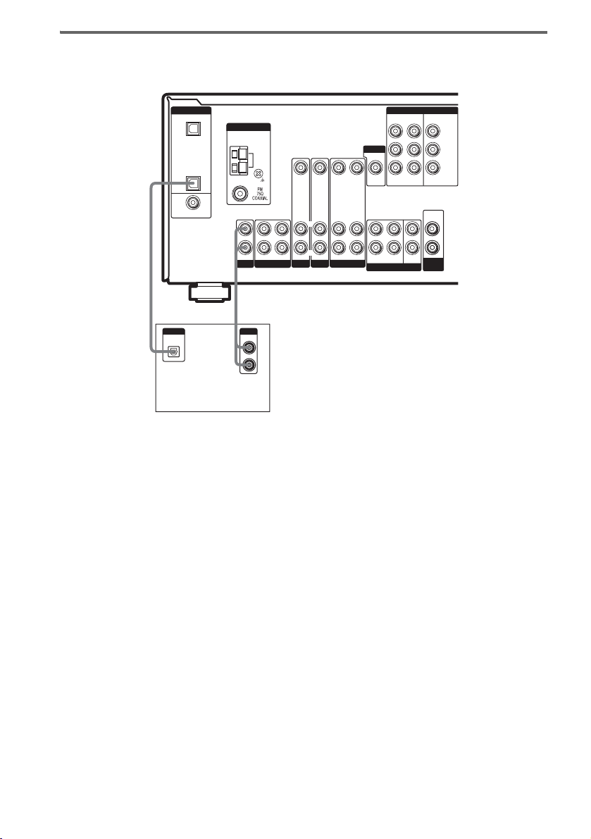
Hooking up a Super Audio CD/CD player
For details on the required cords (A–G), see page 5.
MONITOR
FRONT
MULTI CH IN
COMPONENT VIDEO
ASSIGNABLE
VIDEO 2INMONITOR
DVD
IN
L
CENTER
R
SUB
SURROUND
WOOFER
OUT
AUDIO
OUT
SUB
WOOFER
Y
PB/C
B
/B–Y
P
R/CR
/R–Y
DIGITAL
OPTICAL
VIDEO 2
IN
SA-CD/
CD
IN
DVD
IN
COAXIAL
ANTENNA
L
R
SA-CD/CD
AM
OUT ININ
MD/TAPE
VIDEO IN
L
R
AUDIO IN
DVD
VIDEO IN
VIDEO IN VIDEO OUT
VIDEO OUT
L
L
R
R
AUDIO IN
AUDIO IN
AUDIO OUT
VIDEO 1
VIDEO 2
DA
DIGITAL
OPTICAL
OUT
OUTPUT
LINE
L
R
Super Audio CD/
CD player
Tip
All the digital audio jacks are compatible with 32 kHz, 44.1 kHz, 48 kHz and 96 kHz sampling frequencies.
Note
No sound is output when you play a Super Audio CD on the Super Audio CD player connected to the
SA-CD/CD OPTICAL IN jack on this receiver. Connect the player to the analog input jacks (SA-CD/CD IN jacks).
Refer to the operating instructions supplied with the Super Audio CD player.
GB
8
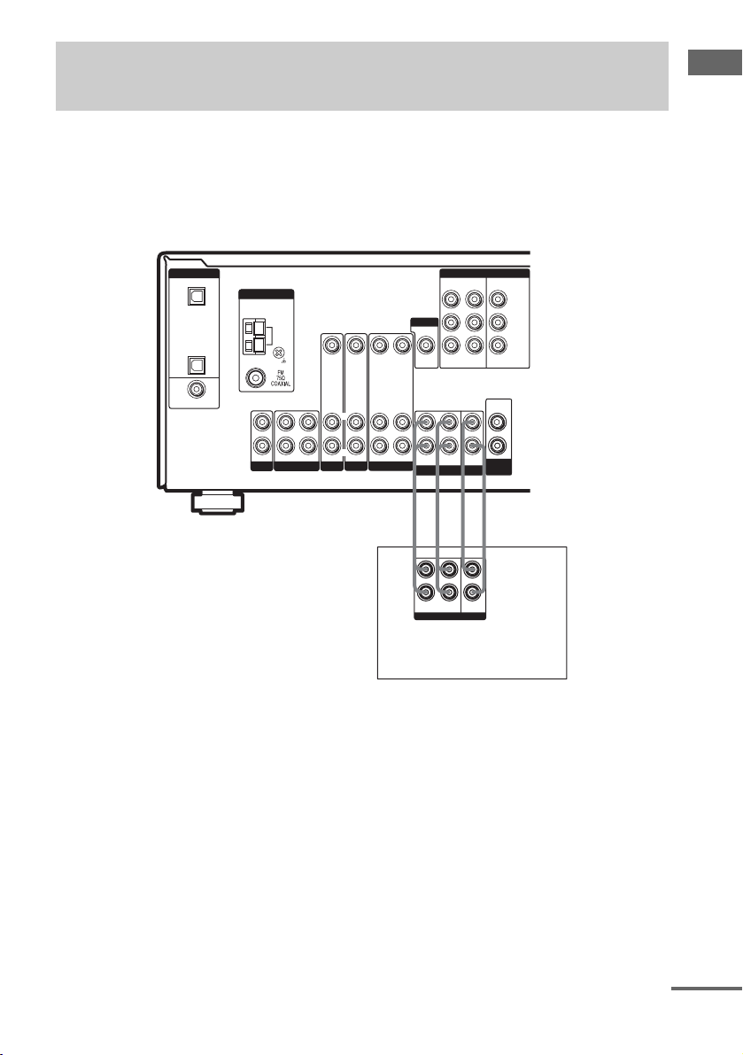
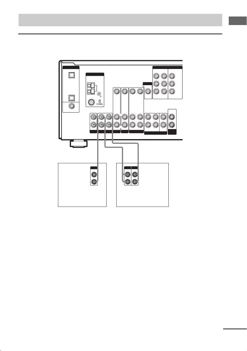
1b: Connecting components with multi channel output jacks
1 Connect the audio jacks.
If your DVD or Super Audio CD player is equipped with multi channel output jacks, you can connect
it to this receiver’s MULTI CH IN jacks to enjoy the multi channel sound. Alternatively, the multi
channel input jacks can be used to connect an external multi channel decoder.
For details on the required cords (A
–G), see page 5.
Getting Started
MONITOR
FRONT
MULTI CH IN
COMPONENT VIDEO
ASSIGNABLE
VIDEO 2INMONITOR
DVD
IN
L
CENTER
R
SUB
SURROUND
WOOFER
OUT
AUDIO
OUT
SUB
WOOFER
Y
PB/C
B
/B–Y
P
R/CR
/R–Y
DIGITAL
OPTICAL
VIDEO 2
IN
SA-CD/
CD
IN
DVD
IN
COAXIAL
ANTENNA
L
R
SA-CD/CD
AM
OUT ININ
MD/TAPE
VIDEO IN
L
R
AUDIO IN
DVD
VIDEO IN
VIDEO IN VIDEO OUT
VIDEO OUT
L
L
R
R
AUDIO IN
AUDIO IN
AUDIO OUT
VIDEO 1
VIDEO 2
AA FF
L
R
Super Audio CD player,
FRONT
SURROUND
MULTI CH OUT
DVD player,
CENTER
SUB
WOOFER
Multi channel decoder, etc.
Tip
This connection also allows you to enjoy software with multi channel audio recorded in formats other than the Dolby
Digital and DTS.
Note
When you make connections to the MULTI CH IN jacks, you will need to adjust the level of the speakers and sub
woofer using the controls on the connected component.
continued
GB
9
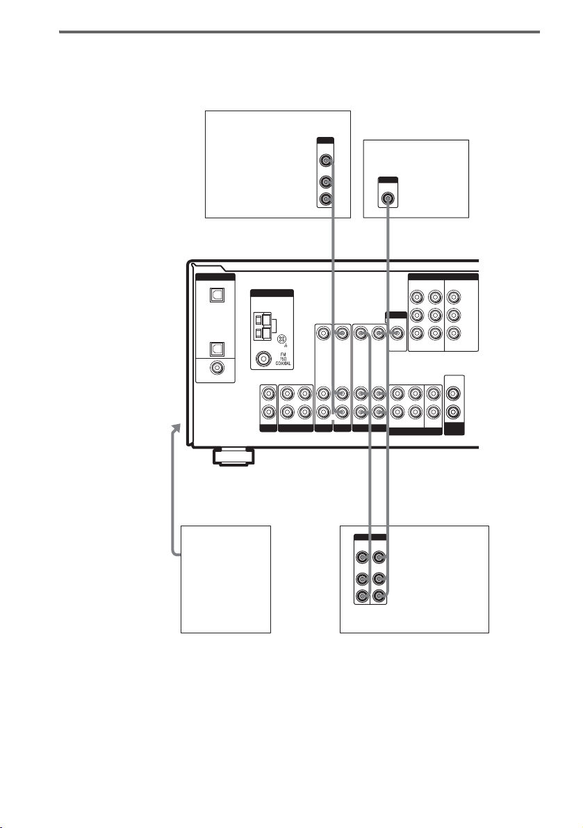
2 Connect the video jacks.
The following illustration shows how to connect a DVD player with COMPONENT VIDEO (Y, PB/
C
/B-Y, PR/CR/R-Y) output jacks. Connecting a TV with component video input jacks allows you to
B
enjoy higher quality video.
TV monitorDVD player
OUTPUT
VIDEO
OUTPUT
COMPONENT
PR/CR/R–Y PB/CB/B–Y
INPUT
Y
VIDEO
INPUT
COMPONENT
PR/CR/R–Y PB/CB/B–Y
Y
GC
Y
P
B/CB
/B–Y
P
R/CR
/R–Y
DIGITAL
OPTICAL
VIDEO 2
IN
SA-CD/
CD
IN
DVD
IN
COAXIAL
ANTENNA
L
R
SA-CD/CD
AM
OUT ININ
MD/TAPE
VIDEO IN
L
R
AUDIO IN
DVD
GC
MONITOR
VIDEO IN
VIDEO IN VIDEO OUT
VIDEO OUT
L
L
R
R
AUDIO IN
AUDIO IN
AUDIO OUT
FRONT
VIDEO 1
VIDEO 2
COMPONENT VIDEO
ASSIGNABLE
DVD
IN
L
R
SURROUND
MULTI CH IN
VIDEO 2INMONITOR
OUT
AUDIO
OUT
CENTER
SUB
WOOFER
SUB
WOOFER
Note
On this receiver, the standard video signals cannot be converted to component video signals (or vice versa).
10
GB
1c: Connecting components with only analog audio jacks
Hooking up audio components
For details on the required cords (A–G), see page 5.
Getting Started
DIGITAL
OPTICAL
VIDEO 2
IN
SA-CD/
CD
IN
DVD
IN
COAXIAL
Super Audio CD/
CD player
ANTENNA
L
R
SA-CD/CD
A
OUTPUT
LINE
AM
OUT ININ
MD/TAPE
L
R
VIDEO IN
L
R
AUDIO IN
DVD
OUT
A
MONITOR
VIDEO IN
VIDEO IN VIDEO OUT
VIDEO OUT
L
L
R
R
AUDIO IN
AUDIO IN
AUDIO OUT
VIDEO 1
VIDEO 2
l
IN
l
A
INPUT OUTPUT
LINE
LINE
L
R
MD/Tape deck
L
R
FRONT
SURROUND
MULTI CH IN
COMPONENT VIDEO
ASSIGNABLE
VIDEO 2INMONITOR
DVD
OUT
IN
AUDIO
OUT
CENTER
SUB
WOOFER
SUB
WOOFER
Y
PB/C
B
/B–Y
P
R/CR
/R–Y
continued
11
GB
Hooking up video components
If you connect your TV to the MONITOR VIDEO OUT jack, you can watch the video from the selected
input (page 21). For details on the required cords (A
Satellite tuner
–G), see page 5.
OUTPUT
VIDEO
OUT
AUDIO
OUT
L
R
B C
INPUT
VIDEO
TV monitor
To the VIDEO 3
IN/PORTABLE
AV IN jacks
(Front panel)
DIGITAL
OPTICAL
VIDEO 2
IN
SA-CD/
CD
IN
DVD
IN
COAXIAL
Camcorder or
video game
ANTENNA
L
R
SA-CD/CD
AM
OUT ININ
MD/TAPE
VIDEO IN
L
R
AUDIO IN
DVD
MONITOR
VIDEO IN
VIDEO IN VIDEO OUT
VIDEO OUT
L
L
R
R
AUDIO IN
AUDIO IN
AUDIO OUT
VIDEO 1
FRONT
VIDEO 2
L
OUT
L
B
BB
OUTPUTINPUT
VIDEO
VIDEO
OUT
IN
AUDIO
AUDIO
OUT
IN
L
R
COMPONENT VIDEO
ASSIGNABLE
DVD
IN
L
R
SURROUND
MULTI CH IN
IN
VCR
VIDEO 2INMONITOR
AUDIO
OUT
CENTER
SUB
WOOFER
SUB
WOOFER
Y
PB/C
B
/B–Y
P
R/CR
/R–Y
OUT
12
GB
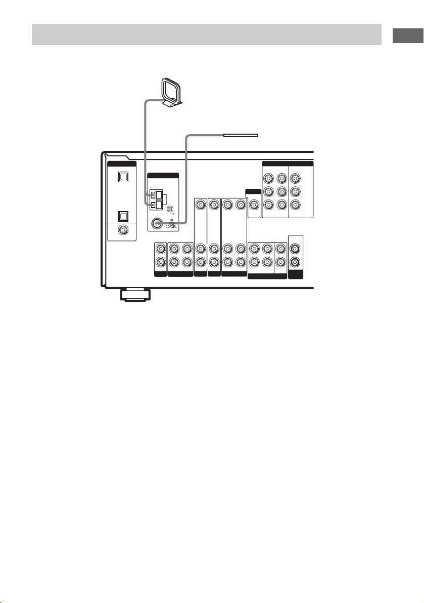
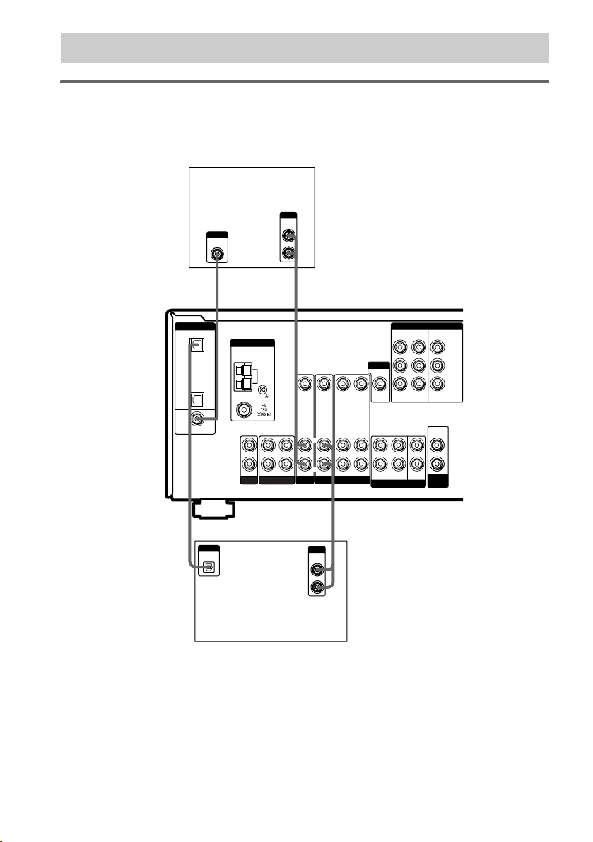
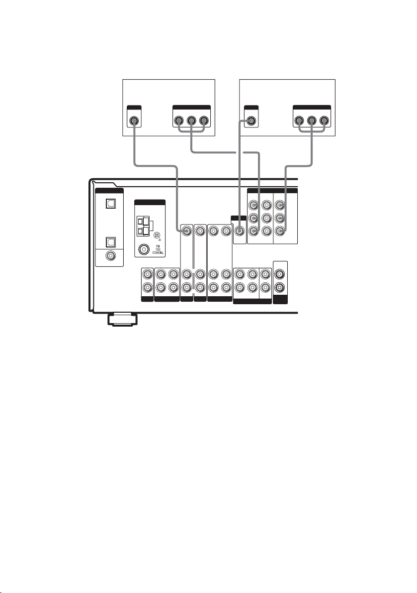
2: Connecting the antennas
Connect the supplied AM loop antenna and FM wire antenna.
AM loop antenna
(supplied)
Getting Started
FM wire antenna
(supplied)
MONITOR
FRONT
MULTI CH IN
COMPONENT VIDEO
ASSIGNABLE
VIDEO 2INMONITOR
DVD
IN
L
CENTER
R
SUB
SURROUND
WOOFER
OUT
AUDIO
OUT
SUB
WOOFER
Y
PB/C
B
/B–Y
P
R/CR
/R–Y
DIGITAL
OPTICAL
VIDEO 2
IN
SA-CD/
CD
IN
DVD
IN
COAXIAL
ANTENNA
L
R
SA-CD/CD
AM
OUT ININ
MD/TAPE
VIDEO IN
L
R
AUDIO IN
DVD
VIDEO IN
VIDEO IN VIDEO OUT
VIDEO OUT
L
L
R
R
AUDIO IN
AUDIO IN
AUDIO OUT
VIDEO 1
VIDEO 2
Notes
• To prevent noise pickup, keep the AM loop antenna away from the receiver and other components.
• Be sure to fully extend the FM wire antenna.
• After connecting the FM wire antenna, keep it as horizontal as possible.
13
GB
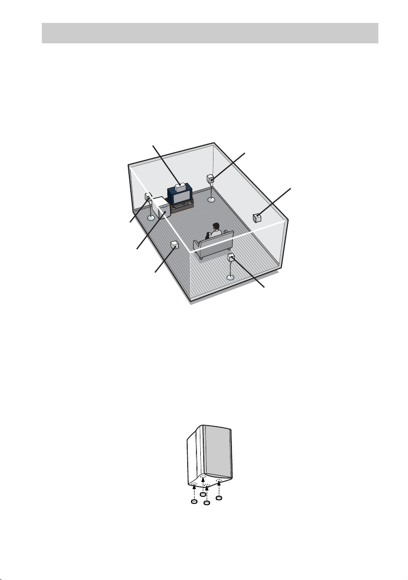
3: Connecting speakers
Connect your speakers to the receiver. This receiver allows you to use a 6.1 channel speaker system.
To fully enjoy theater-like multi channel surround sound requires five speakers (two front speakers, a
center speaker, and two surround speakers) and a sub woofer (5.1 channel).
You can enjoy high fidelity reproduction of DVD software recorded in the Surround EX format if you
connect one additional surround back speaker (6.1 channel) (see “Selecting the surround back decoding
mode” on page 31).
Example of 6.1 channel speaker system configuration
Center speaker
Front speaker (Left)
Sub woofer
Surround speaker (Left)
Front speaker (Right)
Surround speaker (Right)
Surround back speaker
Tips
• When you connect 6.1 channel speaker system, place the surround back speaker behind the listening position.
• Since the sub woofer does not emit highly directional signals, you can place it wherever you want.
Note
Connect the long spea ker connecting cords to the surround an d surround back speaker terminals and th e short speaker
connecting cords to the front and center speaker terminals.
Attaching foot pads
To prevent speaker vibration or movement, attach the supplied foot pads to the speaker (except front
speaker) as shown in the illustration below.
Note
Be sure to attach the supplied foot pads to the sub woofer as well.
GB
14
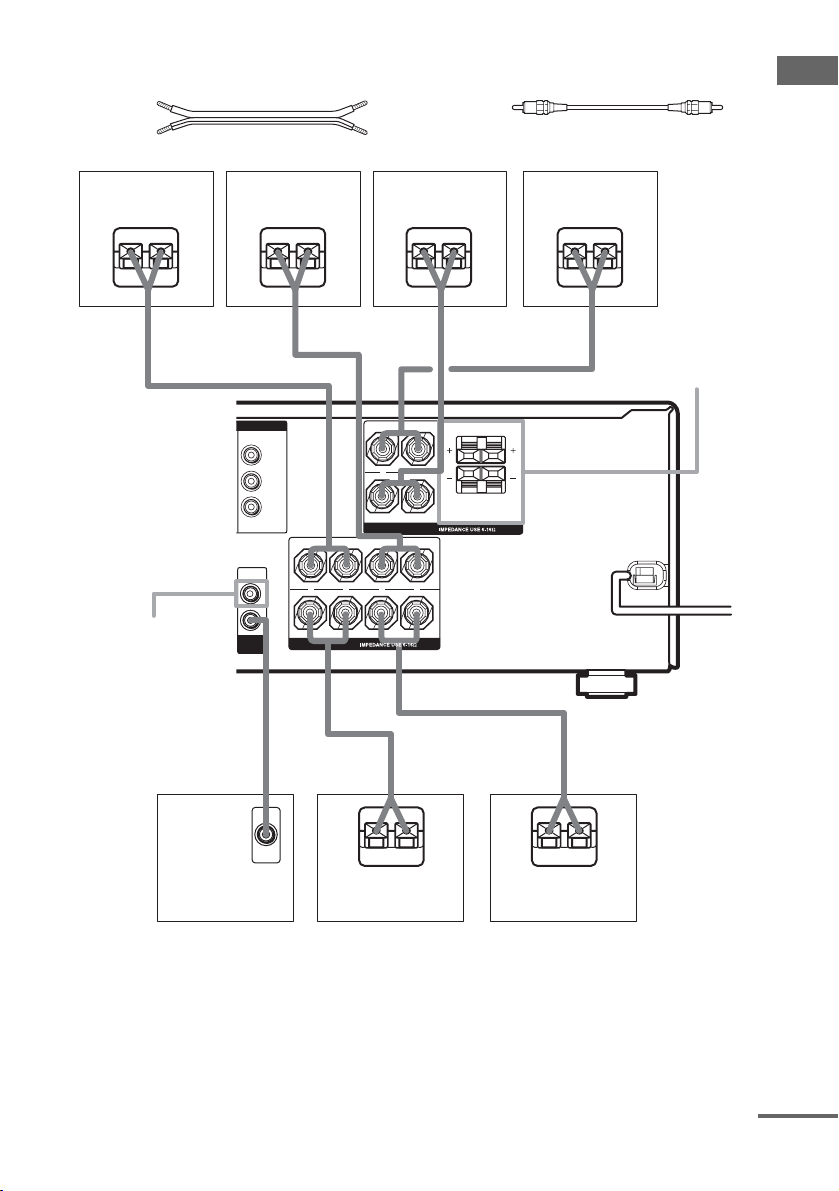
Required cords
S
A Speaker cords (supplied)
(+)
(–)
B Monaural audio cord (supplied)
Black
Getting Started
Front speaker
(Right)
Front speaker
(Left)
Center speaker Surround back
speaker
EeEeEeEe
AA A
+
SPEAKERS
L
LR
SPEAKER
FRONT B*
LR
LR
SUB
WOOFER**
T VIDEO
MONITOR
OUT
AUDIO
OUT
SUB
WOOFER
A
Y
P
B/CB
/B–Y
P
R/CR
/R–Y
+ +
SPEAKERS
R
SURROUND BACK
–
CENTER FRONT B
FRONT A
––
SURROUND
B
Sub woofer
INPUT
A
E
Surround speaker
(Right)
e
E
A
e
Surround speaker
(Left)
* If you have an additional front speaker system, connect them to the SPEAKERS FRONT B terminals. You can
select the front speakers you want to use with the SPEAKERS (OFF/A/B/A+B) button. For details, see “Selecting
the speaker system” (page 39).
** If you have an additional sub woofer, you can connect it to the other SUB WOOFER terminal.
continued
15
GB

Installing the speakers on the
wall
You can install your front, surround and
surround back speakers on the wall.
1 Prepare screws (not supplied) that are
suitable for the hole on the back of
each speaker. See the illustrations
below.
more than 4 mm
more than 25 mm
4.6 mm
3 Hang the speakers on the screws.
Hole on the back of the speaker
4.6 mm
10 mm
10 mm
Hole on the back of the speaker
2 Fasten the screws to the wall. The
screws should protrude 5 to 7 mm.
5 to 7 mm
Notes
• Use screws that are suitable for the wall material and
strength. As a plaster board wall is especially fragile,
attach the screws securely to a beam and fasten them
to the wall. Install the speakers on a vertical and flat
wall where reinforcement is applied.
• Contact a screw shop or installer regarding the wall
material or screws to be used.
• Sony is not responsible for accident or damage
caused by improper installation, insufficient wall
strength or improper screw installation, natural
calamity, etc.
16
GB
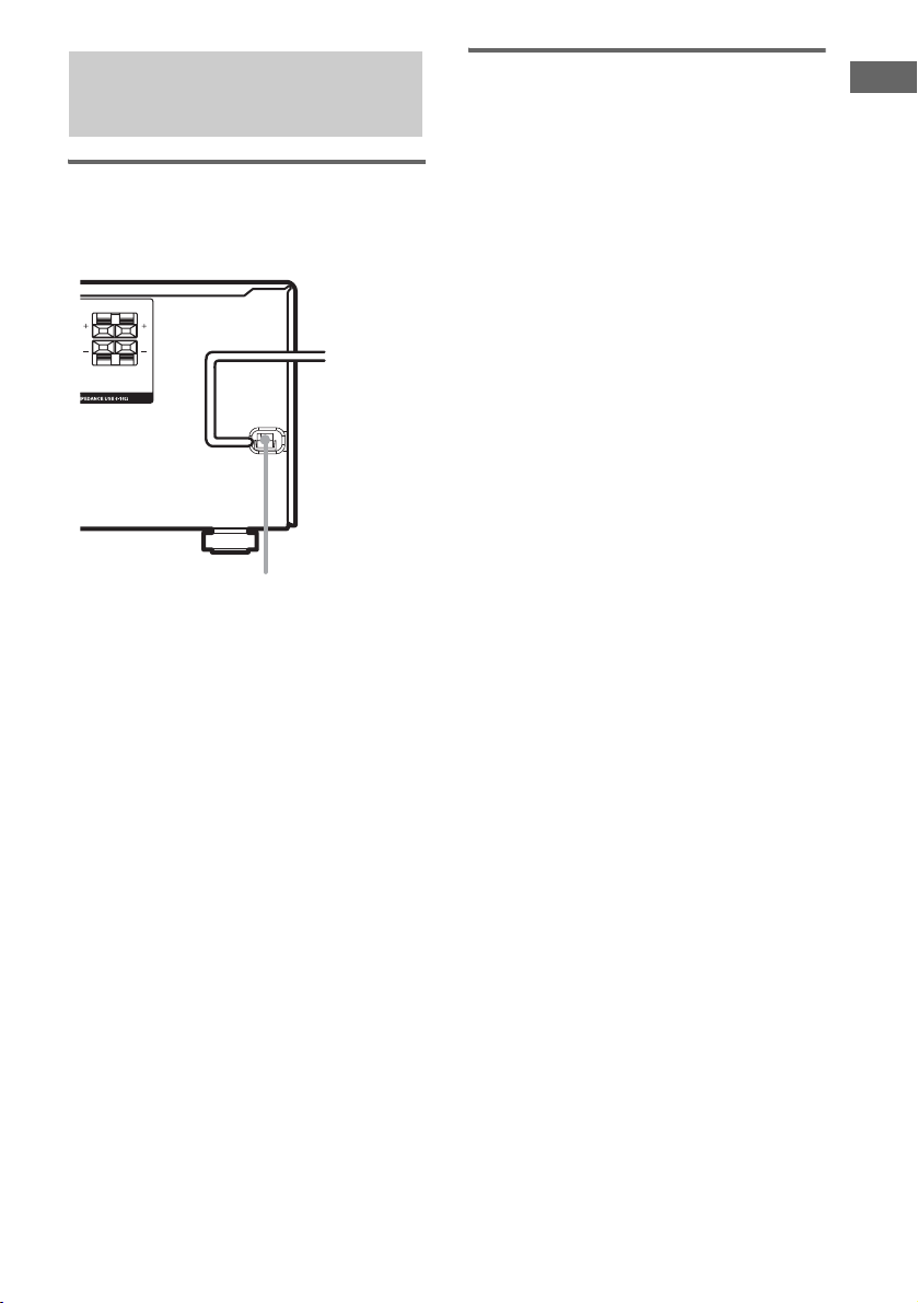
4: Connecting the AC power cord
Connecting the AC power
cord
Connect the AC power cord to a wall outlet.
LR
b
To a wall outlet
FRONT B
LR
AC power cord
Performing initial setup
operations
Before using the receiver for the first time,
initialize the receiver by performing the
following procedure.
This procedure can also be used to return
settings you have made to their factory defaults.
Use the buttons on the receiver for the operation.
1 Press ?/1 to turn off the receiver.
2 Hold down ?/1 for 5 seconds.
“PUSH” and “ENTER” appears in the
display alternatingly.
3 Press ENTER.
“CLEARING” appears in the display for a
while, then “CLEARED” appears.
The following are reset to their factory
settings.
• All settings in the SPEAKER SET UP,
LEVEL, TONE and CUSTOMIZE
menus.
• The sound field memorized for each
input and preset station.
• All sound field parameters.
• All preset stations.
• All index names for inputs and preset
stations.
• MASTER VOLUME –/+ is set to “VOL
MIN”.
Getting Started
17
GB
 Loading...