

Sony HT-6500DP, HT-5500D, HT-17000 Operating Instructions Manual
SONY
FM Stereo
4-238-377-71(l)
;
t
FlUmAIM
Operating Instructions
Owner’s Record
The model and serial numbers are located on the rear panel. Record the serial number
in the space pl-ovided below. Refer to them whenever you call upon your Sony dealer
regarding this product.
Model No. HT-6500DP/SSOOD/I 700D
Receiver
Serial No.
HT-6500DP
HT-5500D
HT- 17000
0 2002 Sony Corporation
To prevent fire or shock hazard, do not
expose the unit to rain or moisture.
To prevent fire, do not cover the ventilation of the
apparatus with newspapers, table-cloths, curtains. etc.
And don’t place lighted candles on the apparatus.
To prevem fire or shock hazard. do not place objects
filled with liquids, such as vases. on the apparatus.
Don’t throw away the battery with
wxwal house waste dispose of it
&ectly as chemical waste.
Do not install the appliance in a confined space. such
as a bookcase or built-in cabinet.
For customers in the United States
- Reorient or relocate the receiving antenna.
-
Increase the separation between the equipment and
receiver.
- Connect the equipment into an outlet on a circuit
different from that to which the receiver is
connected.
- Consult the dealer or an experienced radio/TV
technician for help.
CAUTION
You are cautioned that any changes or modification
not expressly approved in this manual could void
your authority to operate this equipment.
Note to CATV system installer:
This reminder is provided to call CATV system
installer’s attention to Article 820-40 of the NEC that
provides guidelines for proper grounditlg and. in
particular, specifies that the cable ground shall be
connected to the grounding bystem of the building, a\
close to the point of cable entry as pl-actical.
For customers in Canada
CAUTION
TO PREVENT ELECTRIC SHOCK, DO NOT USE
THIS POLARIZED AC PLUG WITH AN
EXTENSION CORD. RECEPTACLE OR OTHER
OUTLET UNLESS THE BLADES CAN BE FULLY
INSERTED TO PREVENT BLADE EXPOSURE.
/‘- \
ENERGY STAR’ i\ ~1 U.S. xgistel-cd
Main unit . . . . . . . . . . . . . . . . . . . . . . . . . . . . . . . . . . . . . . . . . . . . . . .
5
Other Operations
Naming preset stations and program
sources
Recording . . . . . . . . . . . . . . .
. . . . . . . . . . . . . . . . . . . . . . . . . . . . . . . . . . . . . . . . . .
34
34
Hooking Up the Components
Required cords
Antenna hookups
Audio component hookups
Video component hookups
Digital component hookups..
Multi channel input hookups”
Other hookups
.......................................
...................................
....................
....................
............... 10
............. 1 1
.....................................
Hooking Up and Setting Up
the Speaker System
Speaker system hookups ____.__._.__......... 13
Performing initial setup operations . . . 15
Multi channel surround setup _.____.__..... 15
Checking the connections ,._,._.._,_.__.__.__ 2 1
Basic Operations
Selecting the component ___.__.._._.._.._..,, 22
Changing the display
. . . . . . . . . . . . . . . . . 23
6
7
8
9
12
Using the Sleep Timer . . . . . . . . . .._............. 35
Adjustments using the SET UP
button . . . . . . . . . . . . . . . . . . . . . . . . . . . . . . . . . . . . . . . .
Operations Using the Remote
RM-PP411 I’
Before you use your remote
Remote button description..
Selecting the mode of the remote
Programming the remote
................ 37
.................
....... .40
.....................
Operations Using the Remote
RM-U3062’
Before you use your remote __._.__._.....__ 44
Remote button description . . . . . . . . . . . . . . 44
Changing the factory setting of a
function button
. . . . . . . . . . . . . . . . . . . . . 47
35
37
4 1
Enjoying Surround Sound
Automatically decoding the input
audio signal
Selecting a sound field
...................................
........................
Using only the front speakers
(2 Channel
Stereo). ........................
Enjoying stereo sound in multi channel
(Dolby Pro Logic II)” _____._.__.__._.,., 26
Understanding the multi channel
surround displays
Customizing sound fields
..........................
....................
Receiving Broadcasts
Direct tuning
Automatic tuning
Preset tuning
........................................
.................................
........................................
24
24
26
27
28
3 1
32
32
Additional Information
Precautions
Troubleshooting
Specifications
Tables of settings using SURR,
LEVEL, SET UP. BASS and
TREBLE buttons
Adjustable parameters for each
sound field
” Hi-h.iO0DP rlllil 117-~.i00l1 WI!.
HI- I7OOD
..........................................
...................................
......................................
...........................
.....................................
Wll)
48
48
5 I
54
S5
About This Manual
Note for the supplied remote
The instructions in this manual are for models
HT.6500DP. HT-5500D and HT- 17OOD. Check your
model number by looking at the lower right corner of
the front panel. In this manual, the STR-K840P is
used for illustration purpose unless stated otherwise.
Any difference in operation is clearly indicated in the
text, for example, “HT-6500DP only”.
The HT-6500DP consists of:
Receiver
STR-K840P
-Speaker system
l
Front/surround speakers
l
Center speaker
l
Sub woofer
- DVD player
The HT.5500D consists of:
- Receiver
SS-MSP2
SS-CNP2
SA-WMSP4
DVP-NC655P
STR-K840P
- Speaker system
* Front/surround speakers
* Center speaker
. Sub woofer
- DVD player
SS-MSP2
SS-CNP2
SA-WMSP4
DVP-NC6 15
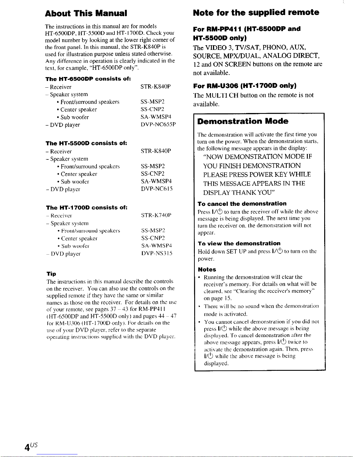
For RM-PP411 (HT-6500DP and
HT.5500D only)
The VIDEO 3, TV/SAT, PHONO, AUX,
SOURCE, MPX/DUAL, ANALOG DIRECT,
12 and ON SCREEN buttons on the remote are
not available.
For RM-U306 (HT.1 7000 only)
The MULTI CH button on the remote is not
available.
Demonstration Mode
The demonstration will activate the first time you
turn on the power. When the demonstration starts,
the following message appears in the display:
“NOW DEMONSTRATION MODE IF
YOU FINISH DEMONSTRATION
PLEASE PRESS POWER KEY WHILE
THIS MESSAGE APPEARS IN THE
DISPLAY THANK YOU”
The HT-1700D consists of:
-Receiver
STR-K740P
- Speaker system
l
Front/surround \peakcrs
- Center speakci. Sub woofei
DVD playei-
Tip
SS-MSP2
SS-CNP?
SA-WMSP4
DVP-NS3I.S
The instructions in this manual describe the controls
on the receiver. You can also use the controls on the
supplied remote if they have the same or similar
names as those on the receiver. For details on the tisc
of your remote, see pages 37 43 for RM-PP411
t HT-6500DP and HT-5500D only 1 and pnges 54 47
for RM-U306 (HT. 170OD only 1. For details on the
n\e of your- DVD player, refer to the separate
open-sting instruction\ supplied with the DVD player.
To cancel the demonstration
Press I/& to turn the receiver off while the above
message is being displayed. The next time you
turn the receiver on. the demonstration will not
appear.
To view the demonstration
Hold down SET UP and press l/b to tnrn on the
power.
Notes
* Running the demonstration will clear the
receiver’s memory. For details on what will be
cleared, see “Clearing the receiver’s memory”
on page 15.
3 There will be no sound when the demonstration
inode is activated.
. You cannot cancel demonstration if you did not
press l/b while the above message is being
displayed. To cancel demonstration after the
ubox me\5age appear,. pres\ I/& twjice to
activate the demonstration again. Then. pi-es\
I/b while the abo\s message is being
displayed.
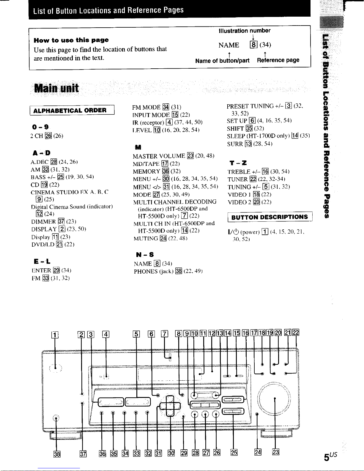
How to use this page
Use this page to find the location of buttons that
are mentioned in the text.
Illustration number
NAME
Name of butTon/part
1
q
(34)
Reierence page
E
8
0,
1
ALPHABETICAL ORDER )
o-3
2 CH •j (26)
A-D
A.DEC q (24,261
AM q (31, 32)
BASS +/- q (19, 30, 54)
CD •j (22)
CINEMA STUDIO EX A. B. C
q
(25)
Di&J Cinema Sound (indicator)
@ (241
DIMMER q (23)
DlSPLAY q (23,501
Display q (23)
DVDlLD q (221
E-L
ENTER •j (34)
FM q (3 I, 32)
FM MODE q (31)
INPUT MODE q (221
IR (receptor) q (37.449501
LEVEL q (I 6,20,28,54)
M
MASTER VOLUME q (20.48)
MD/TAPE q (22)
MEMORY q (32)
MENU +/- q (16.28, 34, 35, 54)
MENU </> q (16, 28.34, 35,541
MODE q (2530,491
MULTI CHANNEL DECODING
(indicator) (HT.6500DP and
HT-5500D only) q (22)
MULTI CH IN (HT-6500DP and
HT.5500D only) q (221
MUTING q (22,481
N-S
NAME q (341
PHONES (jack) q (22,491
PRESET TUNING +I- q (32.
33, 52)
SET UP q (4, 16.35354)
SHIFT q (321 8
SLEEP (HT-1700D only) q (351
SURR q (28,541
1
E
J
P
T-Z
TREBLE +/- q (30,541
TUNER q (22,32-34)
TUNING +/- q (3 I. 32)
VIDEO 1 q (22)
VIDEO 2 •j (221
BUTTON DESCRIPTIONS
I/O (power) q (4. 15. 20, 2 I,
30, 521
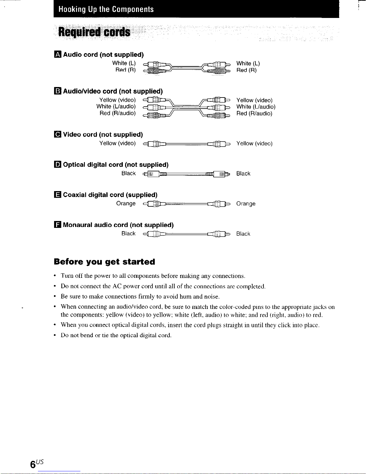
q Audio cord (not supplied)
White (L)
Red (R)
q Audio/video cord (not supplied)
Yellow (video)
White (L/audio)
Red (R/audio)
q Video cord (not supplied)
Yellow (video) ~=$@-JD Yellow (video)
q Optical digital cord (not supplied)
Black
Ol
q Coaxial digital cord (supplied)
Orange a b w Orange
q Monaural audio cord (not supplied)
Black a
White (L)
Red (R)
Yellow (video)
White (L/audio)
Red (R/audio)
Black
<
0 Black
Before you get started
l
Turn off the power to all components before making any connections.
l
Do not connect the AC power cord until all of the connections are completed.
l
Be sure to make. connections firmly to avoid hum and noise.
l
When connecting an audio/video cord, be sure to match the color-coded pins to the appropriate jacks on
the components: yellow (video) to yellow; white (left, audio) to white; and red (right, audio) to red.
l
When you connect optical digital cords, insert the cord plugs straight in until they click into place.
- Do not bend or tie the optical digital cord.
6”*
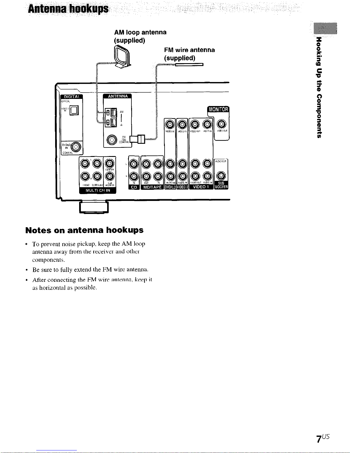
AM loop antenna
(supplied)
FM wire antenna
Notes on antenna hookups
0 To prevent noise pickup, keep the AM loop
antenna away from the receiver and other
components.
* Be sure to fully extend the FM wire antenna.
l
After connecting the FM wire antemw keep it
as horizontal as possible.

MD or Tape deck
I------
8”’
CD player
&
Hooking Up the Components
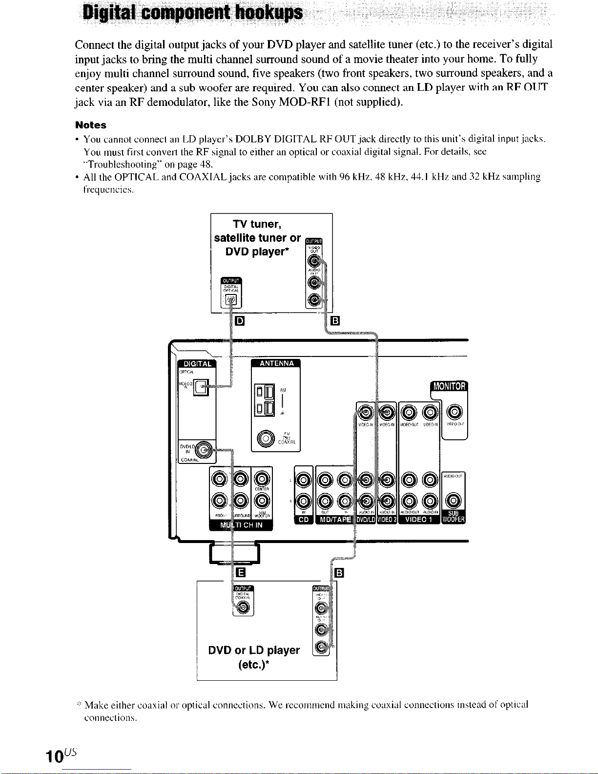
Connect the digital output jacks of your DVD player and satellite tuner (etc.) to the receiver’s digital
input jacks to bring the multi channel surround sound of a movie theater into your home. To fully
enjoy multi channel surround sound, five speakers (two front speakers, two surround speakers, and a
center speaker) and a sub woofer are required. You can also connect an LD player with an RF OUT
jack via an RF demodulator, like the Sony MOD-RF1 (not supplied).
Notes
* You cannot connect an LD player’s DOLBY DIGITAL RF OUT jack directly to this unit’s digital input jack\.
You must first convert the RF signal to either an optical or coaxial digital signal. For details, see
“Troubleshooting” on page 48.
* All the OPTICAL and COAXIAL jacks are compatible with 96 kHz. 48 kHz. 44. I kHr and 32 kHz sampling
frequcncie\.
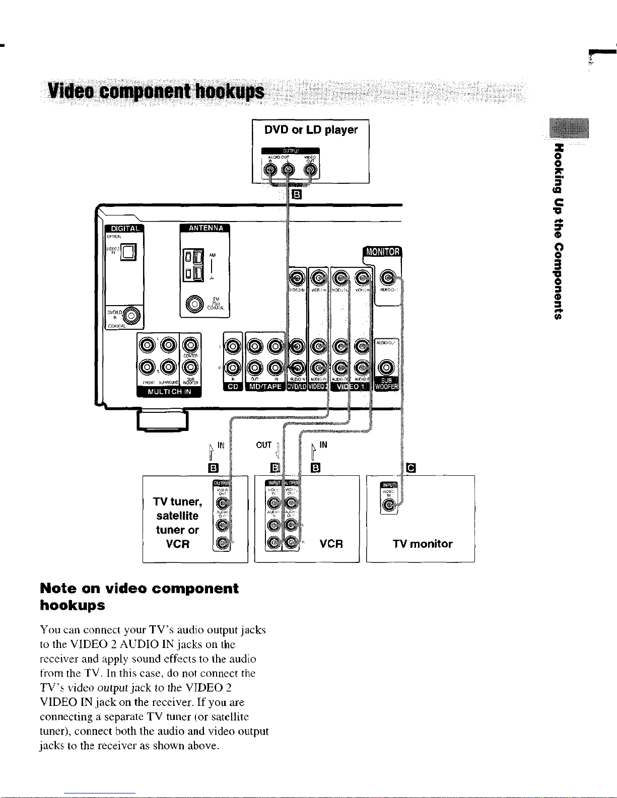
DVD or LD player
(etc.)

HT-6500DP and HT-5500D only
Although this receiver incorporates a multi channel decoder, it is also equipped with multi channel
input jacks. These connections allow you to enjoy multi channel software encoded in formats other
than Dolby Digital and DTS. If your DVD player is equipped with multi channel output jacks, you
can connect them directly to the receiver to enjoy the sound of the DVD player’s multi channel
decoder. Alternatively, the multi channel input jacks can be used to connect an
external
multi channel
decoder.
To fully enjoy multi channel surround sound, five speakers (two front speakers, two surround
speakers, and a center speaker) and a sub woofer are required. Refer to the operating instructions
supplied with your DVD player, multi channel decoder, etc., for details on the multi channel
hookups.
Notes
- When using the connections described below. adjust the level or the surround apcaket-s and sub woofer- firom the
DVD player or multi channel decoder.
* See page I3 for details on speaker system hookup.
E
2
5
9
ti
s
B
ii
8
Multichannel decoder, etc.
DVD player,
11"s
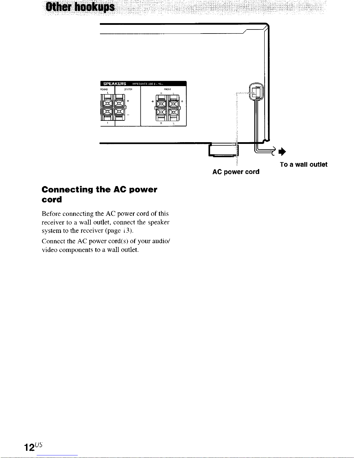
Connecting the AC power
cord
Before connecting the AC power cord of this
receiver to a wall outlet, connect the speaker
system to the receiver (page ~3).
Connect the AC power cord(s) of your audio/
video components to a wall outlet.
To a wall outlet
AC power cord
12"s
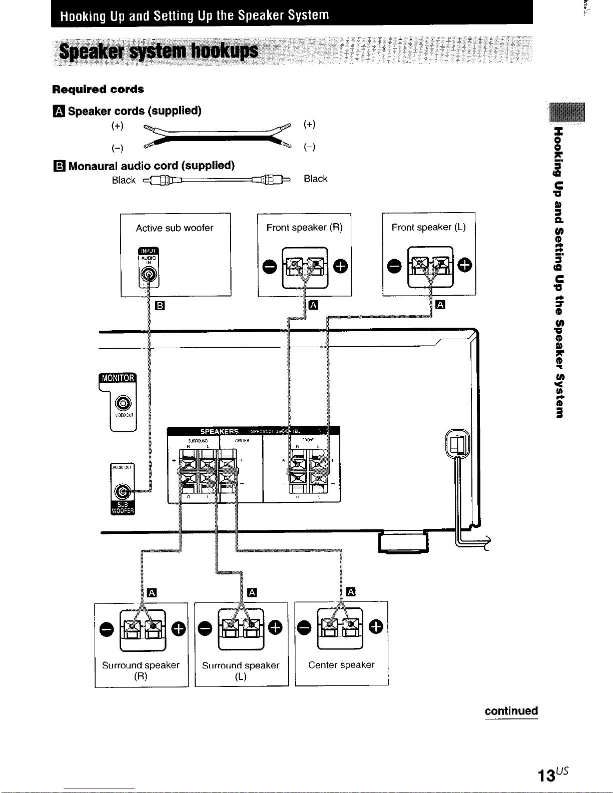
Required cords
q
Speaker cords (supplied)
:I: - :I:
q
Monaural audio cord (supplied)
Black y Black
r
Front speaker (L)
Center speaker Surroun;speaker / 1
continued
13"s
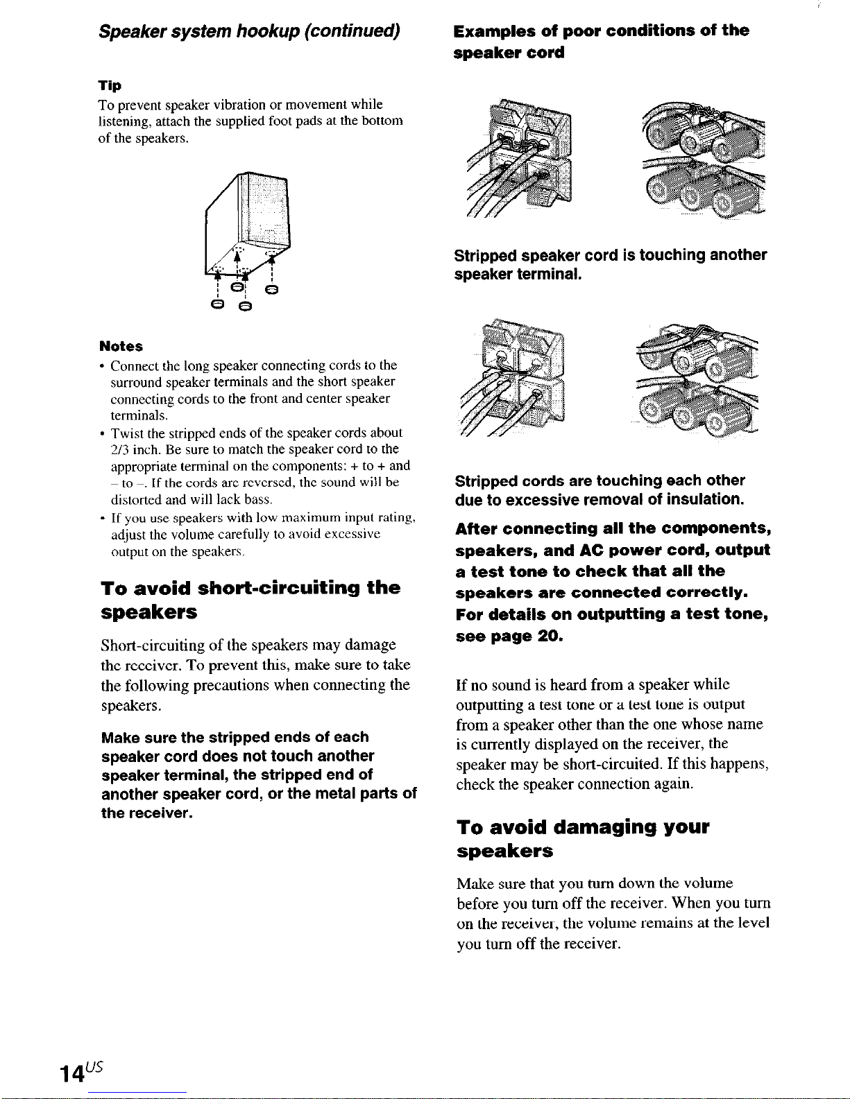
Speaker system hookup (continued)
Tip
To prevent speaker vibration or movement while
listening, attach the supplied foot pads at the bottom
of the speakers.
Notes
l
Connect the long speaker connecting cords to the
surround speaker terminals and the short speaker
connecting cords to the front and center speaker
terminals.
l
Twist the stripped ends of the speaker cords about
2/3 inch. Be sure to match the speaker cord to the
appropriate terminal on the components: + to + and
to -_ If the cords are reversed, the sound will be
distorted and will lack bass.
- If you use speakers with low maximum input rating,
adjust the volume carefully to avoid excessive
output on the speakers.
To avoid short-circuiting the
speakers
Short-circuiting of
the receiver. To prevent this, make sure to take
the following precautions when connecting the
speakers.
Make sure the stripped ends of each
speaker cord does not touch another
speaker terminal, the stripped end of
another speaker cord, or the metal parts of
the receiver.
the speakers may damage
Examples of poor conditions of the
speaker cord
Stripped speaker cord is touching another
speaker terminal.
Stripped cords are touching each other
due to excessive removal of insulation.
After connecting all the components,
speakers, and AC power cord, output
a test tone to check that all the
speakers are connected correctly.
For details on outputting a test tone,
see page 20.
If no sound is heard from a speaker while
outputting a test tone or a test tone is output
from a speaker other than the one whose name
is currently displayed on the receiver, the
speaker may be short-circuited. If this happens,
check the speaker connection again.
To avoid damaging your
speakers
Make sure that you turn down the volume
before you turn off the receiver. When you turn
on the receiver, the volume remains at the level
you turn off the receiver.
Once you have hooked up the speakers and
turned on the power, clear the receiver’s
memory. Then specify the speaker parameters
(size, position, etc.) and perform any other
initial setup operations necessary for your
system.
Tip
To check the audio
while outputting
(page 21).
output during settings (to set up
the sound), check the connection
Clearing the receiver’s
memory
Performing initial setup
operations
Before using your receiver for the first time,
adjust SET UP parameters so that the receiver
correspond to your system. For the adjustable
parameters, see the table on page 54. See pages
15-20 for speaker settings and pages 35-36 for
other settings.
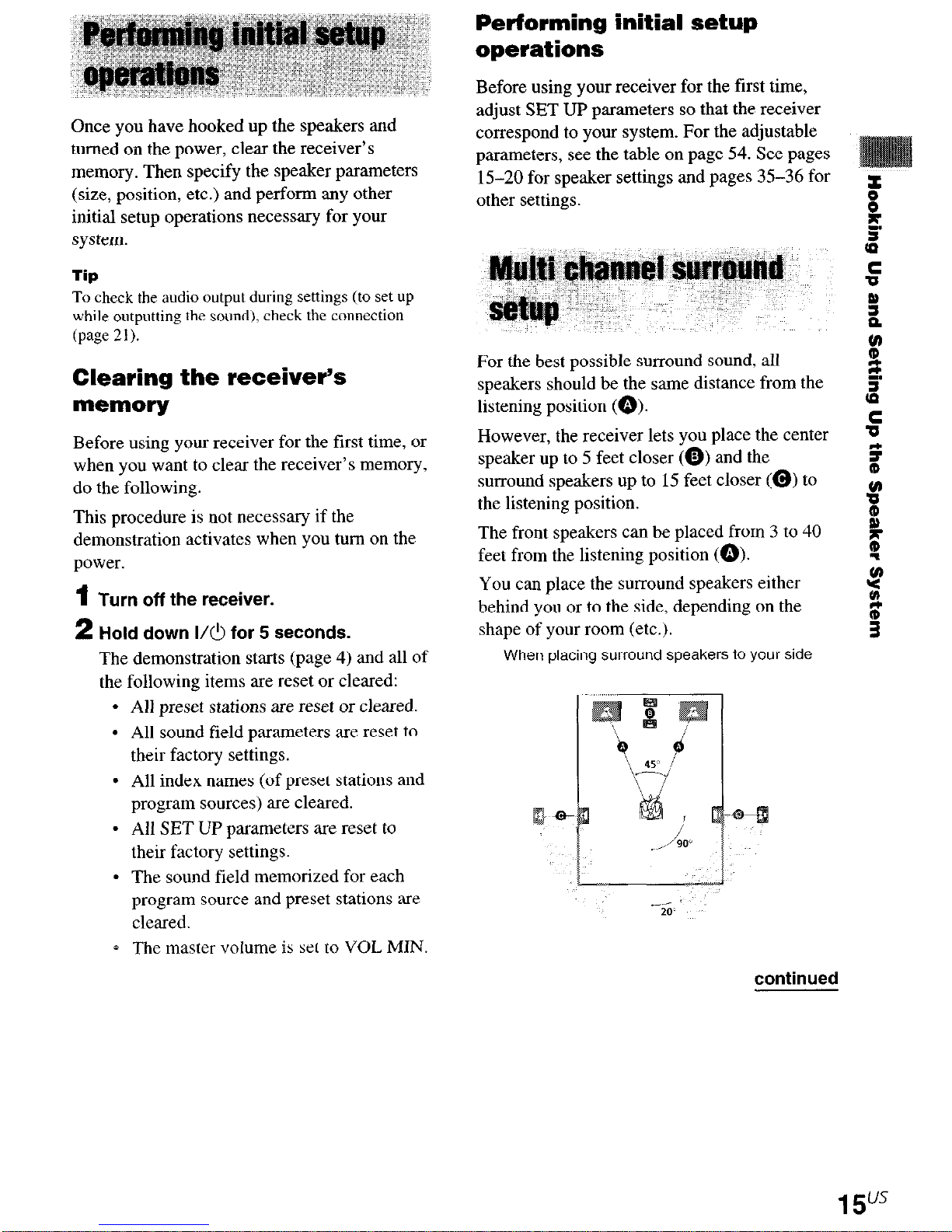
For the best possible surround sound, all
speakers should be the same distance from the
listening position (Q).
Before using your receiver for the first time, or
when you want to clear the receiver’s memory,
do the following.
This procedure is not necessary if the
demonstration activates when you turn on the
power.
1
Turn off the receiver.
2
Hold down I/C! for 5 seconds.
The demonstration starts (page 4) and all of
the following items are reset or cleared:
All preset stations are reset or cleared.
All sound field parameters are reset to
their factory settings.
All index names (of preset stations and
program sources) are cleared.
All SET UP parameters are reset to
their factory settings.
The sound field memorized for each
program source and preset stations are
cleared.
The master volume is set to VOL MIN.
However, the receiver lets you place the center
speaker up to 5 feet closer (0) and the
surround speakers up to 15 feet closer (@) to
the listening position.
The front speakers can be placed from 3 to 40
feet from the listening position (0).
You can place the surround speakers either
behind you or to the side, depending on the
shape of your room (etc.).
When placing surround speakers to your side
continued
15us
Multi channel surround setup
(continued)
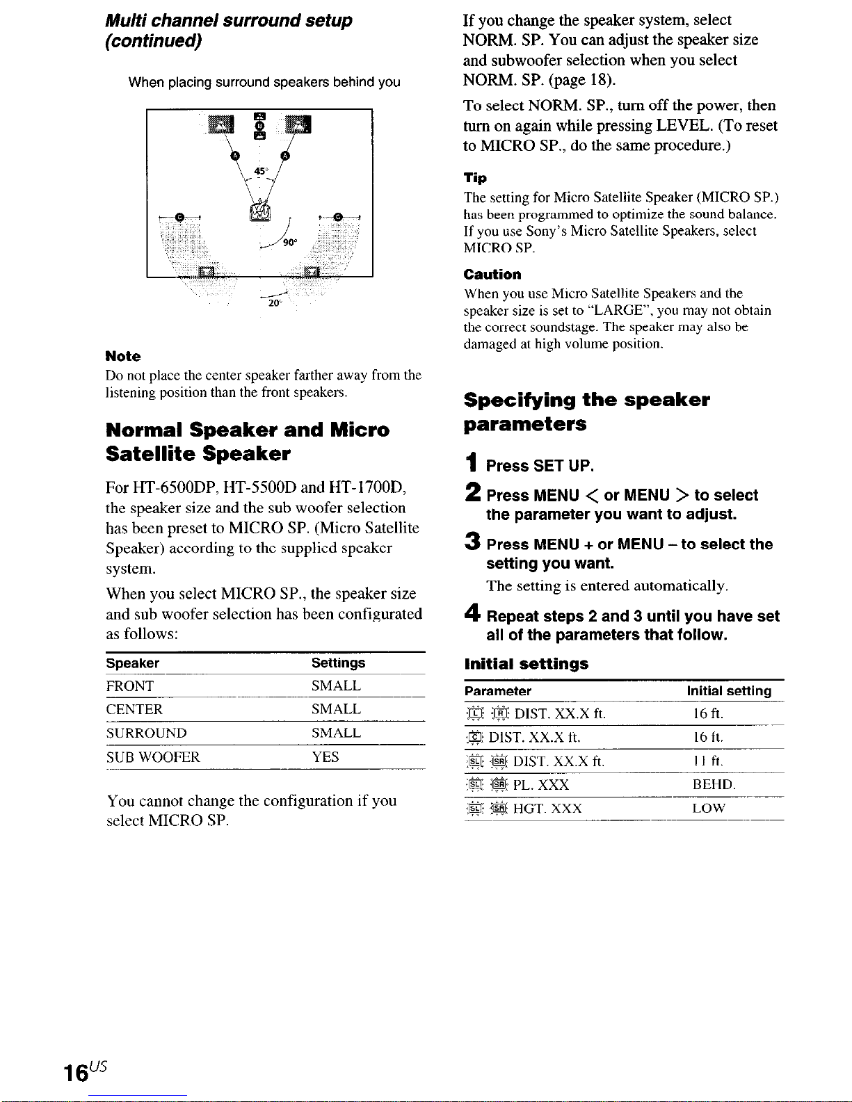
When placing surround speakers behind you
-6
Note
Do not place the center speaker farther away from the
listening position than the front speakers.
Normal Speaker and Micro
Satellite Speaker
For HT-6500DP, HT-5500D and HT-1700D,
the speaker size and the sub woofer selection
has been preset to MICRO SP. (Micro Satellite
Speaker) according to the supplied speaker
system.
When you select MICRO SP., the speaker size
and sub woofer selection has been configurated
as follows:
If you change the speaker system, select
NORM. SP. You can adjust the speaker size
and subwoofer selection when you select
NORM. SP. (page 18).
To select NORM. SP., turn off the power, then
turn on again while pressing LEVEL. (To reset
to MICRO SP., do the same procedure.)
Tip
The setting for Micro Satellite Speaker (MICRO SP.)
has been programmed to optimize the sound balance.
If you use Sony’s Micro Satellite Speakers, select
MICRO SP.
Caution
When you use Micro Satellite Speakers and the
speaker size is set to “LARGE”, you may not obtain
the correct soundstage. The speaker may also be
damaged at high volume position.
Specifying the speaker
parameters
1 Press SET UP.
2 Press MENU < or MENU > to select
the parameter you want to adjust.
3 Press MENU + or MENU -to select the
setting you want.
The
setting
4 Repeat steps 2 and 3 until you have set
all of the parameters that follow.
is entered automatically.
Speaker
FRONT
CENTER
Settings
SMALL
SMALL
SMALL
YES
You cannot change the configuration if you
select MICRO SP.
Initial settings
Parameter
:a :& DIST. Xx.X ft.
@ DIST. Xx.X ft.
:@ :@ DIST. Xx.X ft.
.& :&$I: HGT. XXX
Initial settina
16 ft
16 ft
I I ft.
BEHD
LOW
16"'
n
Front speaker distance (<a: :@I DIST.
xx.x ft.)
Set the distance from your listening position to
the front speakers (0 on page 15).
n
Center speaker distance (@ DIST.
xx.x ft.)
Set the distance from your listening position to
the center speaker. Center speaker distance
should be set from a distance equal to the front
speaker distance (0 on page 15) to a distance
5 feet closer to your listening position (Q on
page 15).
n
Surround speaker distance ($$!$ j$$
DIST. Xx.X ft.)
Set the distance from your listening position to
the surround speakers. Surround speaker
distance should be set from a distance equal to
the front speaker distance (a on page 15) to a
distance 15 feet closer to your listening
position (Q on page 15).
For example, setting the center speaker distance
3-6 feet closer than the actual speaker position will
create a fairly realistic sensation of being “inside” the
screen. If you cannot obtain a satisfactory surround
effect because the surround speakers are too close,
setting the surround speaker distance closer (shorter)
than the actual distance will create a larger sound
stage.
Adjusting these parameter while listening to the
sound often results in much better surround sound.
Give it a try!
n
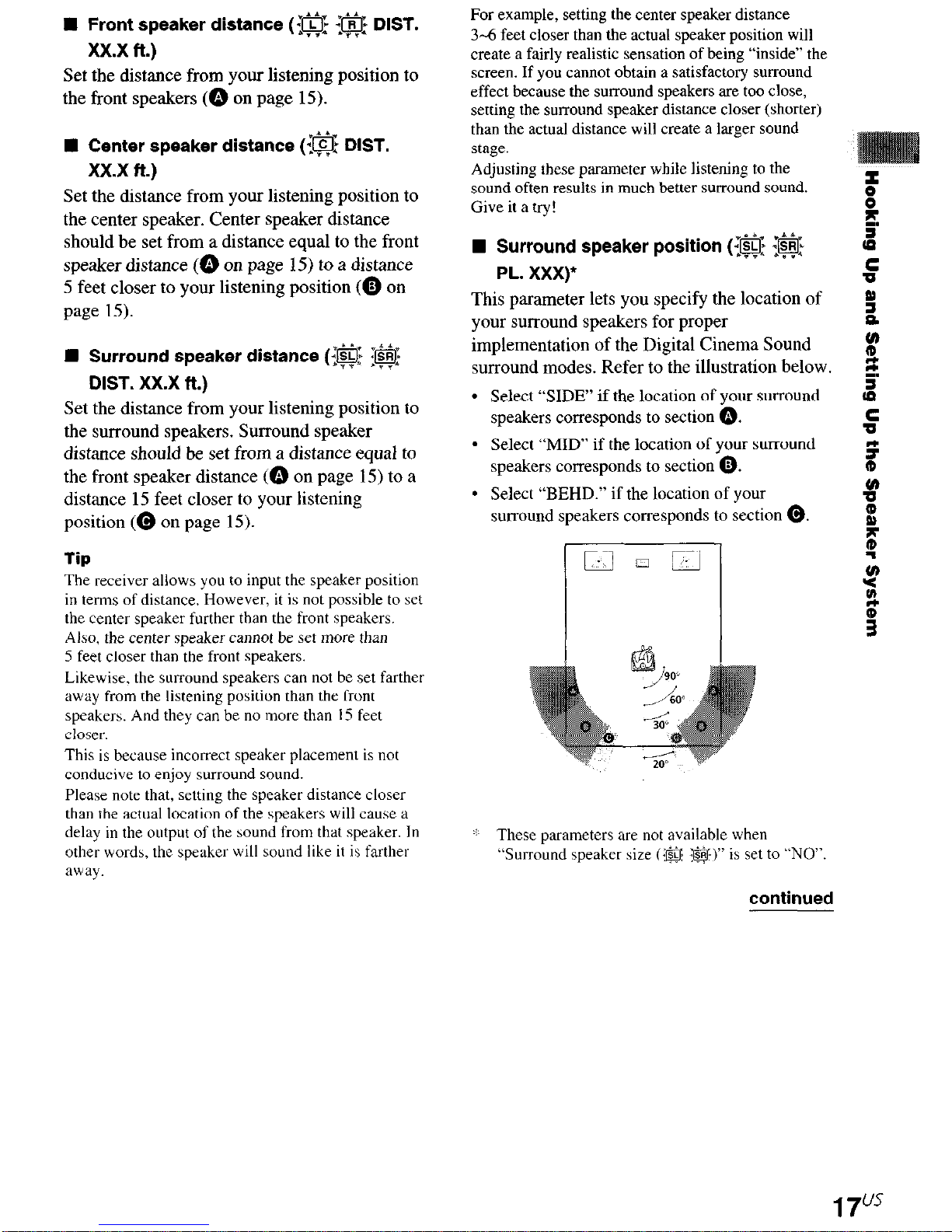
Surround speaker position (@ <@
PL. XXX)
5
e
z
5
This parameter lets you specify the location of 5
your surround speakers for proper
implementation of the Digital Cinema Sound
a
v
surround modes. Refer to the illustration below. g.
l
Select “SIDE” if the location of your surround s
speakers
l
Select “MID” if the location of your surround
speakers corresponds to section 0.
l
Select “BEHD.” if the location of your
surround speakers corresponds to section @.
corresponds to section 0.
s
s
!
z
Tip
The receiver allows you to input the speaker position
in terms of distance, However, it is not possible to set
the center speaker further than the front speakers.
Also, the center speaker cannot be set more than
5 feet closer than the front speakers.
Likewise, the surround speakers can not be set farthet
away from the listening position than the front
speakers. And they can be no more than 15 feet
CIOSW.
This is because incorrect speaker placement is not
conducive to enjoy surround sound.
Please note that, setting the speaker distance closer
than the actual location of the speakers will cause a
delay in the output of the sound from that speaker. In
other words, the speaker will sound like it is farther
away.
: These parameters are not available when
“Surround speaker size (:a @$)” is set to “NO”.
continued
17"s
Multi channel surround setup
(continued)
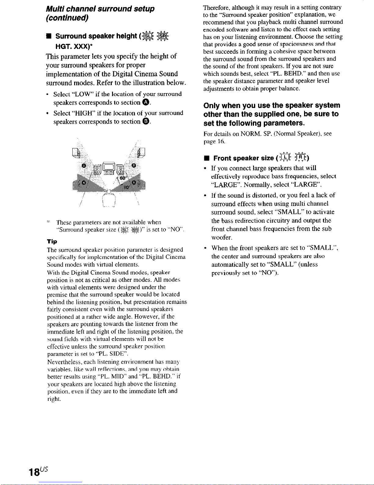
W Surround speaker height (@ @$
HGT. XXX)
This parameter lets you specify the height of
your surround speakers for proper
implementation of the Digital Cinema Sound
surround modes. Refer to the illustration below.
l
Select “LOW” if the location of your surround
speakers corresponds to section 0.
l
Select “HIGH” if the location of your surround
speakers corresponds to section 0.
Therefore, although it may result in a setting contrary
to the “Surround speaker position” explanation, we
recommend that you playback multi channel surround
encoded software and listen to the effect each setting
has on your listening environment. Choose the setting
that provides a good sense of spaciousness and that
best succeeds in forming a cohesive space between
the surround sound from the surround speakers and
the sound of the front speakers. If you are not sure
which sounds best, select “PL. BEHD.” and then use
the speaker distance parameter and speaker level
adjustments to obtain proper balance.
Only when you use the speaker system
other than the supplied one, be sure to
set the following parameters.
For details on NORM. SP. (Normal Speaker), see
page 16.
W Front speaker size (:@I @)
l
If you connect large speakers that will
effectively reproduce bass frequencies, select
“LARGE”. Normally, select “LARGE”.
‘6 These parameters are not available when
“Surround speaker size (@ {a)” is set to “NO“.
lip
The surround speaker position parameter is designed
specifically for implementation of the Digital Cmema
Sound modes with virtual elements.
With the Digital Cinema Sound modes, speaker
position is not as critical as other modes. All modes
with virtual elements were designed under the
premise that the surround speaker would be located
behind the listening position, but presentation remains
fairly consistent even with the surround speakers
positioned at a rather wide angle. However, if the
speakers are pointing towards the listener from the
immediate left and right of the listening position, the
sound fields with virtual elements will not be
effective unless the surround speaker positlon
parameter is set to “PL. SIDE”.
Nevertheless, each listening environment has man)
variables, like wall reflections, and you may obtain
better results using “PL. MID” and “PL. BEHD.” if
your speakers are located high above the listening
position, even if they are to the immediate left and
right.
l
If the sound is distorted, or you feel a lack of
surround effects when using multi channel
surround sound, select “SMALL” to activate
the bass redirection circuitry and output the
front channel bass frequencies from the sub
- When the front speakers are set to “SMALL”,
the center and surround speakers are also
automatically set to “SMALL” (unless
previously set to “NO”).
18"'
n
Center speaker size (:@:)
If you connect a large speaker that will
effectively reproduce bass frequencies, select
“LARGE”. Normally, select “LARGE”.
However, if the front speakers are set to
“SMALL”, you cannot set the center speaker to
“LARGE”.
If the sound is distorted, or you feel a lack of
surround effects when using multi channel
surround sound, select “SMALL” to activate
the bass redirection circuitry and output the
center channel bass frequencies from the front
speakers (if set to “LARGE”) or sub woofer.*’
If you do not connect a center speaker, select
“NO”. The sound of the center channel will be
output from the front speakers.*’
n
Surround speaker size (@ @$:)
If you connect large speakers that will
effectively reproduce bass frequencies, select
“LARGE”. Normally, select “LARGE”.
However, if the front speakers are set to
“SMALL”, you cannot set the surround
speakers to “LARGE”.
Tip
Internally, the LARGE and SMALL settings for each
speaker determine whether or not the internal sound
processor will cut the bass signal from that channel.
When the bass is cut from a channel, the bass
redirection circuitry sends the corresponding bass
frequencies to the sub woofer or other “LARGE”
speakers.
However, since bass sounds have a certain amount of
directionality, it is best not to cut them, if possible.
Therefore, even when using smal1 speakers, you can
set them to “LARGE” if you want to output the bass
frequencies from that speaker. On the other hand, if
you are using a large speaker, but prefer not to have
bass frequencies output from that speaker, set it to
“SMALL”.
If the overall sound level is lower than you prefer, set
all speakers to “LARGE”. If there is not enough bass,
you can use the BASS +/- to boost the bass levels. To
adjust the bass, see page 30.
n
Sub woofer selection (@$ S.W. XXX)
.
If you connect a sub woofer, select “YES”.
.
If you do not connect a sub woofer, select
“NO”. This activates the bass redirection
circuitry and outputs the LFE signals from other
speakers.
If the sound is distorted, or you feel a lack of
surround effects when using multi channel
surround sound, select “SMALL” to activate
the bass redirection circuitry and output the
surround channel bass frequencies from the sub
woofer or other “LARGE” speakers.
If you do not connect surround speakers, select
“NO”,*2
Tip
*l-*3 correspond to the following Dolby Pro Logic
modes
“1
NORMAL
*‘2 PHANTOM
“:3 3 STEREO
continued
19"*
Multi channel surround setup
(continued)
Adjusting the speaker level
Use the remote while seated in your listening
position to adjust the level of each speaker.
Note
The receiver incorporates a new test tone with a
frequency centered at 800 Hz for easier speaker level
adjustment.
1
Press I/& to turn on the receiver.
2 Press TEST TONE on the remote.
“T. TONE” appears in the display and you
will hear the test tone from each speaker in
sequence.
3 Adjust the LEVEL parameters so that
the level of the test tone from each
speaker sounds the same when you are
in your main listening position.
Press LEVEL to adjust the balance and
level of speakers. For details on the LEVEL
menu, see page 28.
While adjusting, the test tone is output from
the speaker whose adjustment is performed.
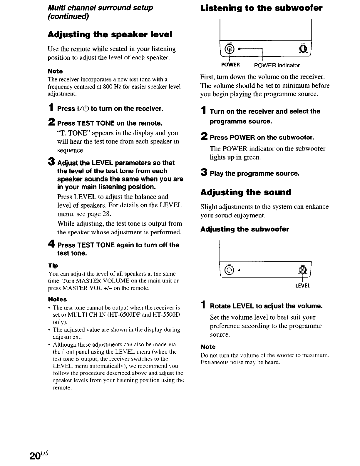
Listening to the subwoofer
POtVER
First, turn down the volume on the receiver.
The volume should be set to minimum before
you begin playing the programme source.
1
Turn on the receiver and select the
programme source.
2 Press POWER on the subwoofer.
The POWER indicator on the subwoofer
lights up in green.
3 Play the programme source.
POWER indicator
Adjusting the sound
Slight adjustments to the system can enhance
your sound enjoyment.
Adjusting the subwoofer
4 Press TEST TONE again to turn off the
test tone.
Tip
You can adjust the level of all speakers at the same
time. Turn MASTER VOLUME on the main unit or
press MASTER VOL +/- on the remote.
Notes
* The test tone cannot be output when the receiver is
set to MULTI CH IN (HT-6500DP and HT-5500D
only).
l
The adjusted value are shown in the display during
adjustment.
l
Although these adjustments can also be made via
the front panel using the LEVEL menu (when the
test tone is output, the receiver switches to the
LEVEL menu automatically), we recommend you
follow the procedure described above and adjust the
speaker levels from your listening position using the
remote.
LEilEL
1
Rotate LEVEL to adjust the volume.
Set the volume level to best suit your
preference according to the programme
source.
Note
Do not turn the volume of the woofer to ma~xm~um.
Extraneous noise may be heard.
2ous
After connecting all of your components to the
receiver, do the following to verify that the
connections were made correctly.
Press I/& to turn on the receiver.
1
2 Turn on the component that you
connected (e.g., CD player or tape
deck).
3 Press the function button to select the
component (program source).
4 Start playing.
If you do not obtain normal sound output after
performing this procedure, see
“Troubleshooting” on page 48 and take the
appropriate measures to correct the problem.
21U5

Function buttons
Press the function button to select the
component you want to use.
Select
OFT IN
ANALOG Specify the analog audio
To
Specify the digital
signals input to the
DIGITAL OPTICAL input
jacks.
signals input to the AUDIO
IN (L/R) iacks.
audio
To select
VCR VIDEO I or VIDEO 2
TV or satellite VIDEO 2
tuner
DVD or LD player DVD/LD
MD or Tape deck MD/TAPE
CD player CD
Built in tuner TUNER
After turning on the component you selected,
select the component and play the program
source.
l
After selecting VCR, DVD player, or LD
player, turn on the TV and set the TV’s video
input to match the component you selected.
Press
INPUT MODE
Press INPUT MODE to select the input mode
for your digital components.
Each time you press the button, the input mode
of the currently selected component switches.
Select To
AUTO IN Give priority to digital
signals when there are both
digital and analog
connections. If there are no
digital signals, analog is
selected.
COAX IN ~~ Specify the digital audio
signals input to the
DIGITAL COAXIAL input
jacks.
Note
If 96 kHz digital signal is input, the tone, sound field
and
surround
MULTI CH IN
HT4500D only)
Press MULTI CH IN to enjoy the audio source
connected to the MULTI CH IN jacks. You can
adjust balance and level of all the speakers. When
this function is on, the tone and surround effects
are turned off.
parameters do not function.
(HT-6500DP and
MULTI CHANNEL DECODING
indicator
HT-5500D only)
This indicator lights up when the unit is
decoding signals recorded in a multi channel
format.
(HT-6500DP and
MUTING
Press MUTING to mute the sound. The muting
function is canceled when you turn the power
on or turn the MASTER VOLUME clockwise
to turn the volume up.
PHONES
Use to connect headphones.
0 When the headphones are connected, speaker
output is automatically canceled and “SP. OFF”
lights up in the display.
DISPLAY
Each time you press DISPLAY, the display
changes cyclically as follows:
Index name of the component* -+ Selected
component + Sound field applied to the
program source
When the tuner is selected
Index name of the preset station* ---,
Frequency + Sound field applied to the band
or the preset station
* Index name appears only when you have assigned
one to the component or preset station (page 34).
Index name does not appear when only blank
spaces have been entered, or it is the same as the
function.
DIMMER
Press DIMMER repeatedly to adjust the
brightness of the display (3 steps).
However, when you press any button, the
display becomes the brightest setting
temporary.
23”’
You can take advantage of surround sound
simply by selecting one of the receiver’s preprogrammed sound fields. They bring the
exciting and powerful sound of movie theaters
and concert halls into your home. You can also
customize the sound fields to obtain the sound
you want by changing the surround parameter.
To fully enjoy surround sound, you must
register the number and location of your
speakers. See “Multi channel surround setup”
starting from page 15 to set the speaker
parameters before enjoying surround sound.
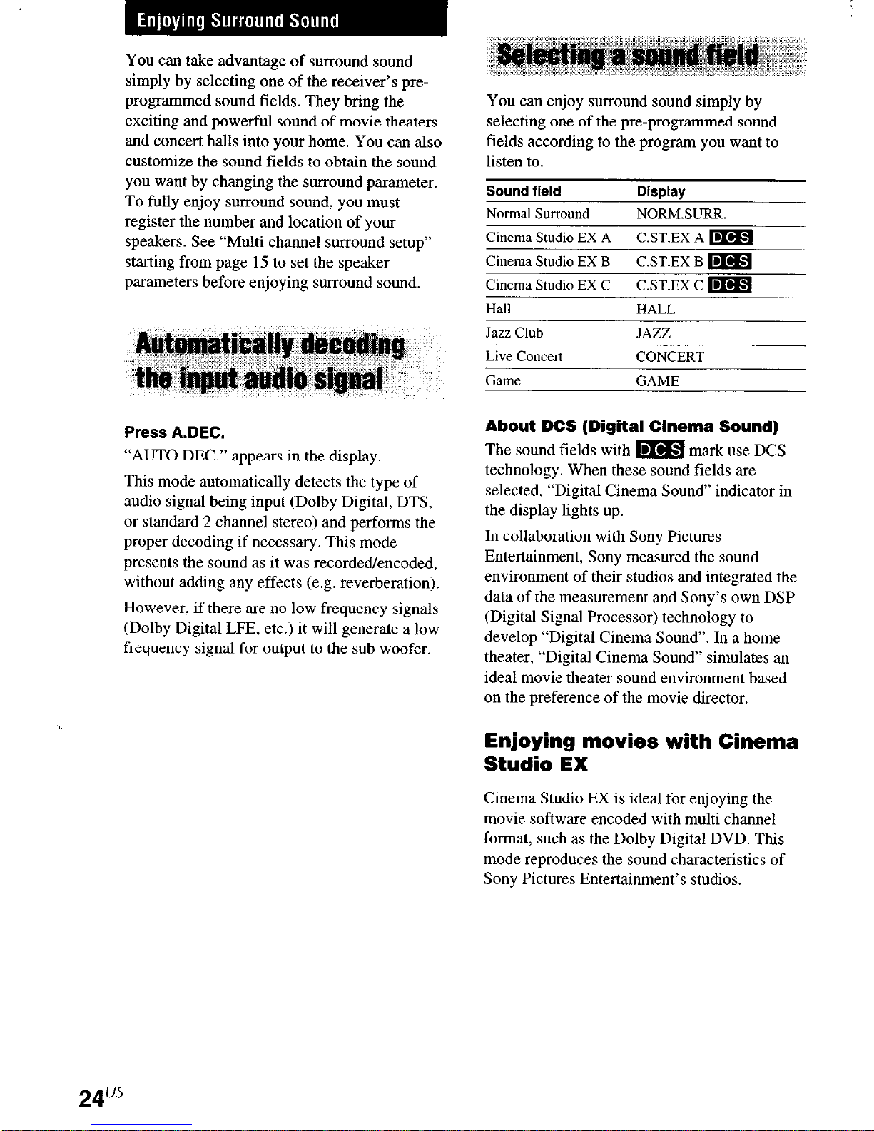
You can enjoy surround sound simply by
selecting one of the pre-programmed sound
fields according to the program you want to
listen to.
Sound field Display
Normal Surround
Cinema Studio EX A
Cinema Studio EX B
Cinema Studio EX C C.ST.EX C m
Hall HALL
Jazz Club JAZZ
Live Concert CONCERT
Game GAME
NORMSURR.
C.ST.EX A m
C.ST.EX B m
Press A.DEC.
“AUTO DEC.” appears in the display.
This mode automatically detects the type of
audio signal being input (Dolby Digital, DTS,
or standard 2 channel stereo) and performs the
proper decoding if necessary. This mode
presents the sound as it was recorded/encoded,
without adding any effects (e.g. reverberation).
However, if there are no low frequency signals
(Dolby Digital LIZ, etc.) it will generate a low
frequency signal for output to the sub woofer.
About DCS (Digital Cinema Sound)
The sound fields with m mark use DCS
technology. When these sound fields are
selected, “Digital Cinema Sound’ indicator in
the display lights up.
In collaboration with Sony Pictures
Entertainment, Sony measured the sound
environment of their studios and integrated the
data of the measurement and Sony’s own DSP
(Digital Signal Processor) technology to
develop “Digital Cinema Sound’. In a home
theater, “Digital Cinema Sound’ simulates an
ideal movie theater sound environment based
on the preference of the movie director.
Enjoying movies with Cinema
Studio EX
Cinema Studio EX is ideal for enjoying the
movie software encoded with multi channel
format, such as the Dolby Digital DVD. This
mode reproduces the sound characteristics of
Sony Pictures Entertainment’s studios.
24”’
Press CINEMA STUDIO EX A, B or C.
The selected sound field is indicated in the
display.
W C.ST.EX A (Cinema Studio EX A)
Reproduces the sound characteristics of the
Sony Pictures Entertainment “Cary Grant
Theater” cinema production studio. This is a
standard mode, great for watching most any
type of movie.
n
C.ST.EX B (Cinema Studio EX B)
Reproduces the sound characteristics of the
Sony Pictures Entertainment “Kim Novak
Theater” cinema production studio. This mode
is ideal for watching science-fiction or action
movies with lots of sound effects.
W C.ST.EX C (Cinema Studio EX C)
Reproduces the sound characteristics of the
Sony Pictures Entertainment scoring stage.
This mode is ideal for watching musicals or
classic films where music is featured in the
soundtrack.
About Cinema Studio EX
Cinema Studio EX consists of the following
three elements.
l
Virtual Multi Dimension
Creates 5 sets of virtual speakers
surrounding the listener from a single pair of
actual surround speakers.
l
Screen Depth Matching
Tip
You can select Cinema Studio EX by pressing MODE
repeatedly.
Notes
l
The effects provided by the virtual speakers may
canse increased noise in the playback signal.
l
When
listening with sound fields that employ the
virtual speakers, you will not be able to hear any
sound coming directly from the surround speakers.
Selecting other sound fields
Press MODE repeatedly to select the
sound field you want.
The current sound field is indicated in the
display.
n
NOFlM.SURR. (Normal Surround)
Software with multi channel surround audio
signals is played back according to the way it
was recorded. Software with 2 channel audio
signals is decoded with Dolby Pro Logic to
create surround effects.
n
HALL
Reproduces the acoustics of a rectangular
concert hall.
H JAZZ (Jazz Club)
Reproduces the acoustics of a jazz club.
n
CONCERT (Live Concert)
Reproduces the acoustics of a 300.seat live
concert.
In a movie theater, sound seems to come
from inside the image reflected on the movie
screen. This element creates the same
sensation in your listening room by shifting
the sound of the front speakers “into” the
screen.
l
Cinema Studio Reverberation
Reproduces the reverberations peculiar to a
movie theater.
Cinema Studio EX is the integrated mode
which operates these elements simultaneously.
n
GAME
Obtains maximum audio impact from video
game software.
continued
2sus
Selecting a sound field (continued)
To turn the surround effect off
Press A.DEC or 2CH.
Tips
l
The receiver lets you apply the last selected sound
field to a program source whenever it is selected
(Sound Field Link). For example, if you listen to
CD with “JAZZ” as the sound field, change to a
different program source, then return to CD,
“JAZZ” willhe applied again.
* You can identify the encoding format of program
sofware by looking at its packaging.
Dolby Digital discs are labeled with the Ulm
logo, and Dolby Surround encoded programs are
labeled with the LXJI~~*W~~N~~ logo.
* When sound signals with a sampling frequency of
96 kHz are input, the sound signals are output in
stereo automatically, and the sound field is turned
off.
PRO. LO(IIC
oca1111
(HT.6500DP and HT-5500D only)
The receiver cart reproduce the stereo sound in
multi channel through
Dolby Pro Logic II. You
can activate the decoder using the SET UP
menu. For details, see page 35
Press 2CH.
“2CH ST.” appears in the display.
This mode outputs the sound from the front left
and
right speakers only. Standard 2 channel
(stereo) sources completely bypass the sound
field processing. Multi channel surround
formats are downmixed to 2 channel.
Notes
* No sound is output from the sub woofer when
“2CH ST.” is selected. To listen to 2 channel
(stereo) sources using the front left and right
speakers and a sub woofer, press A.DEC to select
“AUTO DEC.”
* When you select “Micro Satellite Speaker” (page
16), internal sound processor will automatically
redirect bass sound to subwoofer. If you want to
listen to two channel (stereo) sources under this
setting, we recommend that you choose
“AUTO DEC.” mode so that you can take
advantage of your subwoofer to obtain the correct
bass signal.
26”’
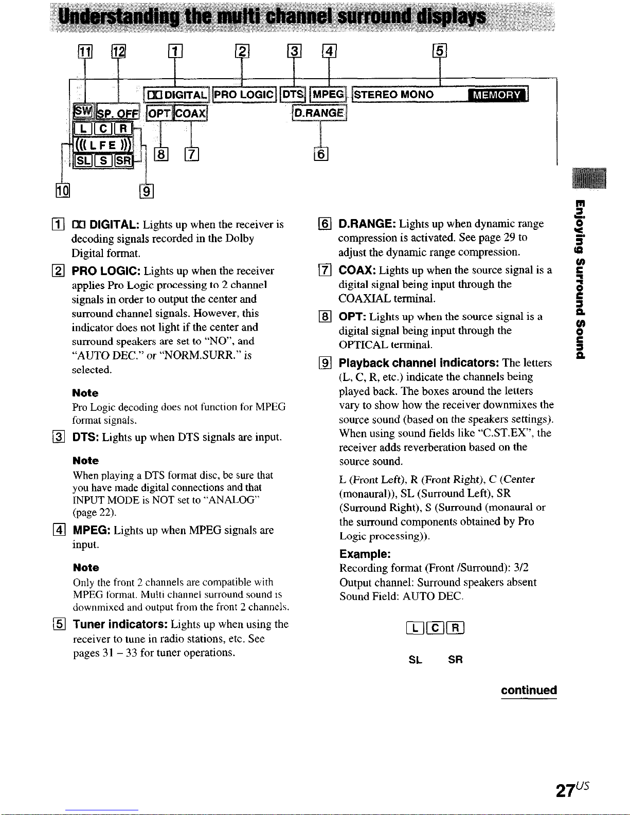
00 DIGITAL: Lights up when the receiver is
decoding signals recorded in the Dolby
Digital format.
DRANGE: Lights up when dynamic range
compression is activated. See page 29 to
adjust the dynamic range compression.
PRO LOGIC: Lights up when the receiver
applies Pro Logic processing to 2 channel
signals in order to output the center and
surround channel signals. However, this
indicator does not light if the center and
surround speakers are set to “NO”, and
“AUTO DEC.” or “NORM.SURR.” is
selected.
Note
Pro Logic decoding does not function for MPEG
format signals.
DTS: Lights up when DTS signals are input.
Note
When playing a DTS format disc, be sure that
you have made digital connections and that
INPUT MODE is NOT set to “ANALOG”
(page
22).
MPEG: Lights up when MPEG signals are
input.
Note
Only the front 2 channels are compatible with
MPEG format. Multi channel surround sound is
downmixed and output from the front 2 channels.
COAX: Lights up when the source signal is a
digital signal being input through the
COAXIAL terminal.
OPT: Lights up when the source signal is a
digital signal being input through the
OPTICAL terminal.
Playback channel indicators: The letters
(L, C, R, etc.) indicate the channels being
played back. The boxes around the letters
vary to show how the receiver downmixes the
source sound (based on rhe speakers settings).
When using sound fields like “C.ST.EX”. the
receiver adds reverberation based on the
source sound.
L (Front Left), R (Front Right), C (Center
(monaural)), SL (Surround Left), SR
(Surround Right), S (Surround (monaural or
the surround components obtained by Pro
Logic processing)).
Example:
Recording format (Front /Surround): 312
Output channel: Surround speakers absent
Sound Field: AUTO DEC.
Tuner indicators: Lights up when using the
receiver to tune in radio stations, etc. See
pages 31 - 33 for tuner operations.
ILIICIIRI
SL SR
continued
27”
Understanding the multi channel
surround displays (continued)
q
((( L F E 1)): Lights up when the disc being
played back contains the LFE (Low
Frequency Effect) channel and when the
sound of the LFE channel signal is actually
being reproduced.
q SW:
Lights up when sub woofer selection is
set to “YES” (page 19) and the audio signal is
output from the SUB WOOFER jacks.
2 Press SURR.
The button lights up and the fist parameter
is displayed.
3
Press MENU + or MENU -to select the
setting you want.
The setting is entered automatically.
Initial settings
Parameter
EFFECT
initial setting
(depends on the sound field)
q SP. OFF:
inserted.
By adjusting the surround parameters and the
tone characteristics of the front speakers, you
can customize the sound fields to suit your
particular listening situation.
Once you customize a sound field, the changes
are stored in the memory indefinitely. You can
change a customized sound field any time by
making new adjustments to the parameters.
See the tables on 55 for the parameters
available in each sound field.
Lights up when headphones are
To get the most from multi
channel surround sound
Position your speakers and do the procedures
described in “Multi channel surround setup”
starting from page 15 before you customize a
sound field.
Effect level (EFFECT)
Lets you adjust the “presence” of the current
surround effect.
Adjusting the level
parameters
The LEVEL menu contains parameters that let
you adjust the balance and volumes of each
speaker. The settings are applied to all sound
fields.
1 Start playing a program source
encoded with multi channel surround
sound.
2 Press LEVEL.
The button lights up and the first parameter
is displayed.
3 Press MENU < or MENU > to select
the parameter you want to adjust.
4 Press MENU + or MENU -to select the
setting you want.
The setting is entered automatically.
Adjusting the surround
parameter
The SURR menu contains parameter that let
you customize various aspects of the current
sound field. The settings are stored individually
for each sound field.
1
Start playing a program source
encoded with multi channel surround
sound.
28”
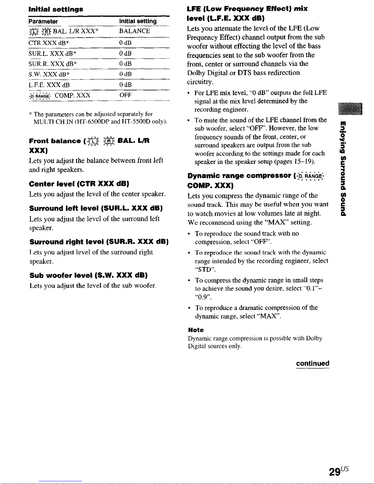
Initial settings
Parameter
{@ -$$f BAL. L/R XXX*
CTR XXX dB*
SUR.L. XXX dB* OdB
SUR.R. XXX dB* OdB
SW. XXX dB*
L.F.E. XXX dB
lo: ,&i&2> COMP. XXX
S”“....
initial setting
BALANCE
OdB
OdB
OdB
OFF
-
* The parameters can be adjusted separately for
MULTI CH IN (HT.6500DP and HT.5500D only).
Front balance ({a :@ BAL. L/R
XXX)
Lets you adjust the balance between front left
and right speakers.
Center level (CTR XXX dB)
Lets you adjust the level of the center speaker.
Surround left level (SURL. XXX dB)
Lets you adjust the level of the surround left
speaker.
Surround right level (SURR. XXX dB)
Lets you adjust level of the surround right
speaker.
Sub woofer level (S.W. XXX dB)
Lets you adjust the level of the sub woofer.
LFE (Low Frequency Effect) mix
level (L.F.E. XXX dB)
Lets you attenuate the level of the LFE (Low
Frequency Effect) channel output from the sub
woofer without effecting the level of the bass
frequencies sent to the sub woofer from the
front, center or surround channels via the
Dolby Digital or DTS bass redirection
circuitry.
For LEE mix level, “0 dB” outputs the full LFE
signal at the mix level determined by the
recording engineer.
To mute the sound of the LFE channel from the
sub woofer, select “OFF’. However, the low
frequency sounds of the front, center, or
surround speakers are output from the
sub
woofer according to the settings made for each
speaker in the speaker setup (pages 15-19).
Dynamic range compressor (-G
&GE’+
*sv*v.*
COMP. XXX)
Lets you compress the dynamic range of the
sound track.
This
may be useful when you want
to watch movies at low volumes late at night.
We recommend using the “MAX” setting.
To reproduce the sound track with no
compression, select “OFF”.
To reproduce the sound track with the dynamic
range intended by the recording engineer, select
“STD.
To compress the dynamic range in small steps
to achieve the sound you desire, select “O.l”“0.9”.
To reproduce a dramatic compression of the
dynamic range, select “MAX”.
Note
Dynamic
Digital sources only.
range compression is possible with Dolby
continued
2gus
Customizing sound fields (continued)
Adjusting the bass and treble
The BASS +/- and TREBLE +/-button lets
you adjust the tone (bass or treble) of the front
speakers for optimum sound. You can adjust
the tone for each separate sound field.
1 Start playing a program source
encoded with multi channel surround
sound.
2 Press BASS +I- or TREBLE +I- to
adjust the tone.
The setting is stored automatically.
Initial settings
Parameter
BASS
TREB.
Bass (BASS)
Initial setting
OdB
0 dB
Lets you adjust the bass tone
Treble (TREB.)
Lets you adjust the treble tone.
Note
When you use the Micro Satellite Speakers or other
small speakers, adjust LEVEL on the subwoofer
(page 20) to reinforce the bass.
Resetting customized sound
fields to the factory settings
1 lf the power is on, press l/b to turn off
the power.
2 Hold down MODE and press I/b.
“SF. CLR.” appears in the display and all
sound fields are reset at once.
3ou5
 Loading...