

Sony HSRX-216-P Service manual

DIGITAL SURVEILLANCE RECORDER
HSR-X209P
HSR-X216/X216P
SERVICE MANUAL
1st Edition

! WARNING
This manual is intended for qualified service personnel only.
To reduce the risk of electric shock, fire or injury, do not perform any servicing other than that
contained in the operating instructions unless you are qualified to do so. Refer all servicing to
qualified service personnel.
! WARNUNG
Die Anleitung ist nur für qualifiziertes Fachpersonal bestimmt.
Alle Wartungsarbeiten dürfen nur von qualifiziertem Fachpersonal ausgeführt werden. Um die
Gefahr eines elektrischen Schlages, Feuergefahr und Verletzungen zu vermeiden, sind bei
Wartungsarbeiten strikt die Angaben in der Anleitung zu befolgen. Andere als die angegeben
Wartungsarbeiten dürfen nur von Personen ausgeführt werden, die eine spezielle Befähigung
dazu besitzen.
! AVERTISSEMENT
Ce manual est destiné uniquement aux personnes compétentes en charge de l’entretien. Afin
de réduire les risques de décharge électrique, d’incendie ou de blessure n’effectuer que les
réparations indiquées dans le mode d’emploi à moins d’être qualifié pour en effectuer d’autres.
Pour toute réparation faire appel à une personne compétente uniquement.
HSR-X209P/X216/X216P

CAUTION
ADVARSEL
Danger of explosion if battery is incorrectly replaced.
Replace only with the same or equivalent type
recommended by the manufacturer.
Dispose of used batteries according to the
manufacturer’s instructions.
Vorsicht!
Explosionsgefahr bei unsachgemäßem Austausch
der Batterie.
Ersatz nur durch denselben oder einen vom
Hersteller empfohlenen ähnlichen Typ. Entsorgung
gebrauchter Batterien nach Angaben des
Herstellers.
ATTENTION
Il y a danger d’explosion s’il y a remplacement
incorrect de la batterie.
Remplacer uniquement avec une batterie du même
type ou d’un type équivalent recommandé par le
constructeur.
Mettre au rebut les batteries usagées conformément
aux instructions du fabricant.
Lithiumbatteri - Eksplosjonsfare.
Ved utskifting benyttes kun batteri som
anbefalt av apparatfabrikanten.
Brukt batteri returneres
apparatleverandøren.
VARNING
Explosionsfara vid felaktigt batteribyte.
Använd samma batterityp eller en likvärdig typ
som rekommenderas av apparattillverkaren.
Kassera använt batteri enligt gällande
föreskrifter.
VAROITUS
Paristo voi räjähtää jos se on virheellisesti
asennettu.
Vaihda paristo ainoastaan laitevalmistajan
suosittelemaan tyyppiin.
Hävitä käytetty paristo valmistajan ohjeiden
mukaisesti.
ADVARSEL!
Lithiumbatteri-Eksplosionsfare ved fejlagtig
håndtering.
Udskiftning må kun ske med batteri
af samme fabrikat og type.
Levér det brugte batteri tilbage til leverandøren.
HSR-X209P/X216/X216P
1 (P)

Attention-when the product is installed in Rack:
1. Prevention against overloading of branch circuit
When this product is installed in a rack and is
supplied power from an outlet on the rack, please
make sure that the rack does not overload the supply
circuit.
2. Providing protective earth
When this product is installed in a rack and is
supplied power from an outlet on the rack, please
confirm that the outlet is provided with a suitable
protective earth connection.
3. Internal air ambient temperature of the rack
When this product is installed in a rack, please make
sure that the internal air ambient temperature of the
rack is within the specified limit of this product.
4. Prevention against achieving hazardous
condition due to uneven mechanical loading
When this product is installed in a rack, please make
sure that the rack does not achieve hazardous
condition due to uneven mechanical loading.
5. Install the equipment while taking the operating
temperature of the equipment into consideration
For the operating temperature of the equipment, refer
to the specifications of the Operation Manual.
For the customers in the Netherlands
Voor de klanten in Nederland
Dit apparaat bevat een (CF)
n-Li batterij voor memory
back-up.
Raadpleeg uw leverancier over de verwijdering van de
batterij op het moment dat u het apparaat bij einde
levensduur afdankt.
Gooi de batterij niet weg. maar lever hem in als KCA.
Bij dit produkt zijn batterijen geleverd.
Wanneer deze leeg zijn, moet u ze niet
weggooien maar inleveren als KCA.
6. When performing the installation, keep the rear of
the unit 10 cm (4 inches) or more away from walls
in order to obtain proper exhaust and radiation of
heat.
2 (P)
HSR-X209P/X216/X216P

Table of Contents
Manual Structure
Purpose of this manual .............................................................................................. 3
Related manuals......................................................................................................... 3
Contents ..................................................................................................................... 3
Caution for Handling the Unit with Built-in HDDs .................................................. 4
1. Installation
1-1. Installation Work Procedure .......................................................................1-1
1-2. Supplied Accessories ..................................................................................1-1
1-3. Operational Environment ............................................................................ 1-1
1-4. Installation Space ........................................................................................ 1-2
1-5. Power Supply .............................................................................................. 1-2
1-5-1. Voltage and Power Requirements ..............................................1-2
1-5-2. Power Cord ................................................................................. 1-2
1-6. Optional Accessories ................................................................................... 1-3
1-7. Rack Mounting ............................................................................................ 1-3
1-8. Hard Disk Drive Unit ..................................................................................1-4
1-9. Matching Connectors and Cables................................................................ 1-4
2. Service Overview
2-1. Main Parts Location .................................................................................... 2-1
2-2. Removing and Installing the Cabinet ..........................................................2-2
2-3. Removing and Installing the Main Parts .....................................................2-3
2-3-1. Removing and Installing the Power Unit ................................... 2-3
2-3-2. Removing and Installing the Fan Motor ....................................2-3
2-3-3. Removing and Installing the HDD Units ................................... 2-4
2-4. Removing and Installing the Board............................................................. 2-5
2-4-1. Removing and Installing the PC-2 Board ..................................2-5
2-4-2. Removing and Installing the PC-1 Board ..................................2-5
2-4-3. Removing and Installing the TB-2 Board and
the Backup Battery .....................................................................2-6
2-4-4. Removing and Installing the CD-1 Board .................................. 2-6
2-4-5. Removing and Installing the TB-4 Board .................................. 2-8
2-4-6. Removing and Installing the VD-1 Board .................................2-8
2-4-7. Removing and Installing the CP-1 and TB-1 Boards ................. 2-9
2-4-8. Removing and Installing the OP-1 and OP-2 Boards ..............2-10
2-5. Adjustment after Replacing the Boards .................................................... 2-10
2-6. Safety Related Components List ...............................................................2-11
HSR-X209P/X216/X216P
1

3. Alignment
3-1. Preparations ................................................................................................. 3-1
3-1-1. Equipment Required ................................................................... 3-1
3-1-2. Preparations before Alignment ..................................................3-1
3-2. OSD Position Adjustment ...........................................................................3-2
3-3. Output Signal Level Adjustment ................................................................. 3-2
3-4. Input Signal Level Adjustment 1 ................................................................ 3-3
3-5. Input Signal Level Adjustment 2 ................................................................ 3-3
3-6. Input Signal Level Difference Confirmation .............................................. 3-4
3-7. Frequency Adjustment ................................................................................ 3-4
4. Spare Parts
4-1. Notes on Repair Parts .................................................................................. 4-1
4-2. Exploded Views .......................................................................................... 4-2
4-3. Electrical Parts List ..................................................................................... 4-6
4-4. Packing Materials & Supplied Accessories ................................................ 4-6
5. Block Diagram
5-1. Circuit Description ......................................................................................5-1
5-2. Overall ......................................................................................................... 5-5
2
HSR-X209P/X216/X216P

Purpose of this manual
Related manuals
Manual Structure
This manual is the Service Manual of the digital surveillance recorder HSR-X209P/
X216/X216P.
This manual contains the maintenance information of this equipment, and servicing
information necessary for parts replacement, adjustments, parts list and overall block
diagram.
n
The figures in this manual are HSR-X209P unless otherwise specified.
In addition to this Service Manual, the following manuals are provided.
..
. Operating Instructions
..
HSR-X216 (Supplied with equipment)
Parts number : 3-207-317-0X
..
. Operating Instructions
..
HSR-X209P/X216P (Supplied with equipment)
Parts number : 3-207-317-0X (For UC, CE)
3-207-318-0X (For CE)
Contents
The sections covered in the manual are summarized below to give you a general
understanding of the manual.
Section 1 Installation
Describes the installation procedure and environment required during installation
and the connection with external equipment.
Section 2 Service Overview
Describes the replacement procedure of parts during repairing of this unit, the
locations of the main parts and boards, and notes on servicing.
Section 3 Alignment
Describes the adjustment procedure after boards replacement.
Section 4 Spare Parts
Describes the exploded views, the mechanical parts list, and the electrical parts list.
Section 5 Block Diagram
Describes the circuit description and overall block diagram.
HSR-X209P/X216/X216P
3

Caution for Handling the Unit with Built-in HDDs
This unit has a built-in hard disk drive (HDDs). Pay careful attention to the followings and perform
operations with extra care when installing, servicing, and maintaining this unit.
Never give any mechanical shock and vibration
This may cause an HDD trouble or destroy the data in HDD.
. Pack this unit using the specified packing materials when carrying the unit. Use a cart with less-
vibration when carrying this unit by a cart. If an excessive mechanical shock and vibration are applied,
the HDD may be damaged.
. Never move this unit under power-on state. Take out or insert this unit from or into the rack in a state of
powering off. Also never install or remove the cabinet under power-on state.
. When putting the unit on the floor, put this unit gently with the four specified feet which is attached to
the bottom of the unit on the floor. If there are no feet on the bottom, attach them before putting this
unit, or put this unit gently so that no sound is generated.
Never operate the unit for 30 seconds after the power is turned off
The disks in HDD rotate by inertia for a while after the power is turned off. In this case, the heads are in
the unstable state. During this period, the HDD is more sensitive to a mechanical shock and vibration than
during power on state. Never give even a slight shock at least 30 seconds after the power is turned off.
Operations can be initiated (because the disks stop) after 30 seconds or more.
In the event of trouble in HDD
If there is something wrong with the HDD of this unit (a failure occurs in the HDD), handle this unit in
the same manner as described above. This protects the HDD from increase of the damage till confirming
the contents of the failure or analyzing the failure.
Pay careful attention to the following when handlings the HDD alone.
Notes when carrying or keeping the HDD
Pack the HDD using the specified packing materials when carrying or keeping the HDD. Moreover,
choose the method which the HDD is not subject to the vibration when carrying.
4
HSR-X209P/X216/X216P

Notes when replacing the HDD
Follow the procedure (described in Section 1) when replacing the HDD.
. If an excessive mechanical shock and vibration are applied, the unpacked HDD may be damaged.
Place the unpacked HDD in a horizonal position (with the printed board side up). Moreover, it is
recommended that the unpacked HDD is put on the specified HDD cushion.
. Use the specified shockless torque screwdriver when tightening and removing the screw during
replacing the HDD.
The HDD cushion and shockless torque screwdriver are available as a fixture.
HDD cushion : Part No. J-6530-060-A
Shockless torque screwdriver : Part No. J-6530-070-A
. HDD is easily affected by static electricity. Take measures against static electricity such as establish-
ing a ground, then install the HDD.
Handling of failed HDD
Handle the HDD that is removed because of a trouble or failure in the same manner as a normal HDD
following above precautions.
HSR-X209P/X216/X216P
5

Section 1
Installation
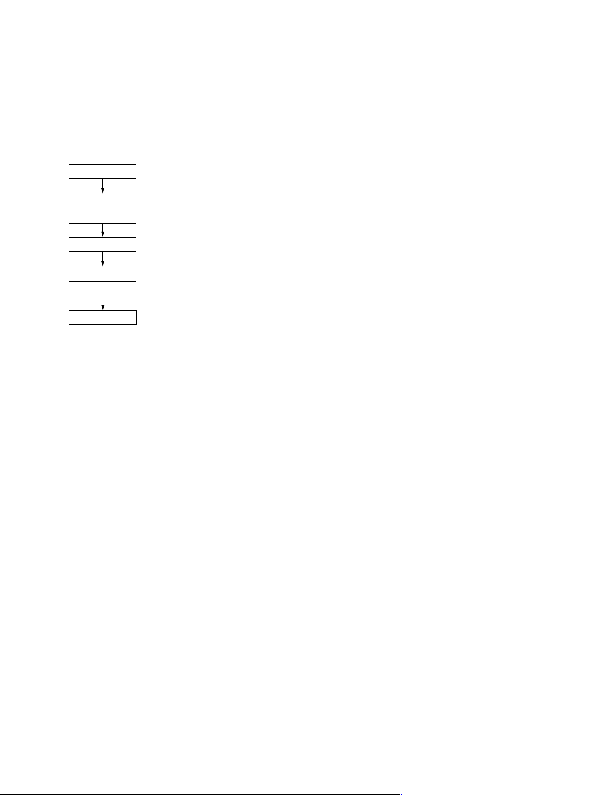
1-1. Installation Work Procedure
Install HSR-X209P/X216/X216P to satisfy the requirements of operating environment and those of
installation space as shown below.
Start
Determination of
installation place
Unpacking
Connectors
End
· · · 1-3.
· · · 1-4. Installation Space
· · · 1-5. Power Supply
· · · 1-2. Supplied Accessories
· · · 1-9. Matching Connectors and Cables
Operational Environment
1-2. Supplied Accessories
. AC power cord: 1
. Power cord tie: 1
. Ferrite core: 2 (HSR-X209P/X216P only)
. Rack mount brackets: 1 set
. Operating instructions: 1 (For HSR-X216)
2 (For HSR-X209P/X216P)
1-3. Operational Environment
. Warranted operating temperature: +5 dC to +40 dC
. Warranted high humidity operation: Less than 80 %
. Horizontal leveling: within ± 30 d
. Do not install in a location subject to: . Extreme cold or hot temperature exceeding the operating
temperature
. Direct sunlight for long hours or near heating apparatus
. High humidity or excessive dust
. Mechanical vibration
. Strong magnetism
. Strong radio wave near TV or radio transmitter
. Do not give strong mechanical shocks
. Do not block ventilator holes
HSR-X209P/X216/X216P
1-1
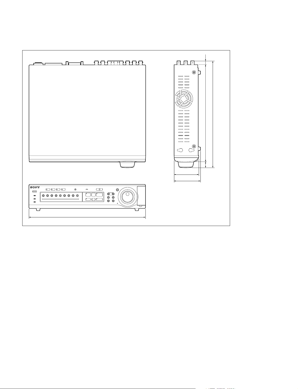
1-4. Installation Space
Weight: 7 kg
86
96
10
349
17
376
420
Unit: mm
1-5. Power Supply
1-5-1. Voltage and Power Requirements
HSR-X216 HSR-X209P/X216P
. Power voltage: AC 120 V . Power voltage: AC 220 V to 240 V
. Power frequency: 60 Hz . Power frequency: 50/60 Hz
. Current consumption: 0.56 A . Current consumption: 0.34 A (For HSR-X209P)
. Rush current: 25 A 0.35 A (For HSR-X216P)
. Rush current: 27 A
1-5-2. Power Cord
w
Use the supplied power cord.
Do not use cords other than the supplied power cord. This may cause a fire or electric shock.
Use the power cord supplied with equipment.
1-2
HSR-X209P/X216/X216P
1-6. Optional Accessories
. Memory stick (8 MB) MSA-8AN . Memory stick (with memory select function)
. Memory stick (16 MB) MSA-16AN (128 MB x 2) MSA-128S2
. Memory stick (32 MB) MSA-32AN . Memory stick PRO (256 MB) MSX-256
. Memory stick (64 MB) MSA-64AN . Memory stick PRO (512 MB) MSX-512
. Memory stick (128 MB) MSA-128AN . Memory stick PRO (1 GB) MSX-1G
. Memory stick/PC card adaptor MSAC-PC2
. Memory stick/PC card adaptor MSAC-PC3
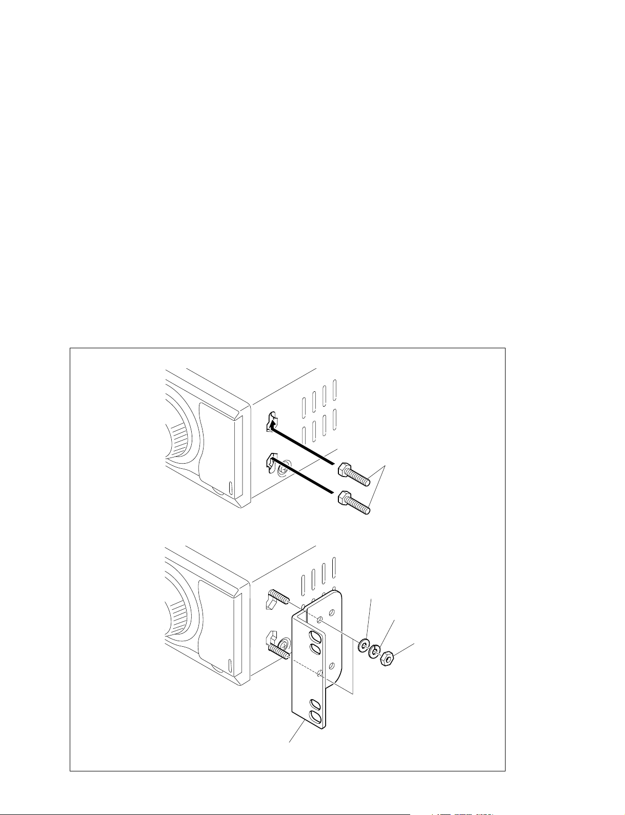
1-7. Rack Mounting
These rack mounting brackets are used to secure this unit to the rack by using the nut grooves on both
sides. This unit can be fixed using supplied hexagonal bolts, nuts, washers, and spring washers.
1. Insert the two supplied hexagonal bolts into the nut grooves on the side of this unit.
2. Fix the bracket using supplied washers, spring washers and nuts.
3. On the opposite side, fix the rack mount bracket in the order of steps 1 and 2.
Rack mount bracket
Bolts (Hex 4 x 3)
Washer
Washer
Nut (N4)
HSR-X209P/X216/X216P
1-3

1-8. Hard Disk Drive Unit
n
Be careful not to give any shocks to hard disk when removing and attaching the hard disk unit.
Caution for Handling the HDD
Refer to “Caution for Handling the Unit with Built-in HDDs” (described after Manual Structure) for
handling the hard disk drive unit and hard disk drive, and perform operations with extra care.
Moreover, pack the failed hard disk drive using specified packing materials when a failure occurs in the
hard disk drive, then contact your local Sony Sales Office/Service Center.
. HDD cushion
It is recommended to use the HDD cushion for protecting the hard disk drive on operating.
. Shockless torque screwdriver
Use the shockless torque screwdriver when tightening the screws during replacing the hard disk drive.
If the traditional torque screwdriver is used, it may be applied a fatal shock to the hard disk drive by the
click of torque screw driver. Be sure to use the shockless torque screwdriver.
When the set torque is reached using the shockless torque screwdriver, the shockless screwdriver turns
free approx. 90 d without shock.
Tools
Torque screwdriver’s bit: J-6323-430-A
(+3 mm, length = 50 mm)
HDD cushion: J-6530-060-A
Shockless torque screwdriver (12 kg.cm): J-6530-070-A
n
Be sure to use the specified shockless torque screwdriver when tightening screws described in this
section.
Never use a ratchet-type traditional torque screwdriver.
1-9. Matching Connectors and Cables
When external cables are connected to the connector of this unit, the hardware listed below (or equivalents) must be used.
Panel indicaton Matching connector/cable Sony part No.
AUDIO IN, OUT RCA PIN JACK ——
MIC MINI JACK ——
MONITOR 1/S VIDEO YC-15V (1.5 m) ——
MONITOR 1, 2 BNC 75 Z 1-569-370-12
IN 1-9 (For HSR-X209P) BNC 75 Z 1-569-370-12
IN 1-16 (For HSR-X216/X216P) 3C-2V COAXIAL CABLE ——
OUT 1-9 (For HSR-X209P) BNC 75 Z 1-569-370-12
OUT 1-16 (For HSR-X216/X216P) 3C-2V COAXIAL CABLE ——
RS-232C D-SUB 9P, FEMALE 1-563-815-21
RS485 A, B RJ-11 ——
3C-2V COAXIAL CABLE ——
1-4
HSR-X209P/X216/X216P
 Loading...