

Sony HSR-X206, HSR-X206P Operating Instructions Manual

3-992-425-11(1)
Digital Surveillance
Recorder
Operating Instructions
HSR-X206/X206P
2004 Sony Corporation
Owner’s Record
The model and serial numbers are located on the body of the
unit. Record the serial number in the space provided below.
Refer to these numbers whenever you call upon your Sony
dealer regarding this product.
Model No. Serial No.
You are cautioned that any changes or modifications not
expressly approved in this manual could void your authority
to operate this equipment.
All interface cables used to connect peripherals must be
shielded in order to comply with the limits for a digital device
pursuant to Subpart B of Part 15 of FCC Rules.
If you have any questions about this product, you may call:
Sony’s Business Information Center (BIC) at 1-800-686SONY(7669) or http://www.sony.com/
WARNING
To reduce the risk of fire or electric shock,
do not expose this apparatus to rain or
moisture.
To avoid electrical shock, do not open the
cabinet. Refer servicing to qualified
personnel only.
THIS APPARATUS MUST BE EARTHED.
WARNING
This unit has no power switch.
When installing the unit, incorporate a readily accessible
disconnect device in the fixed wiring, or connect the power
cord to socket-outlet which must be provided near the unit
and easily accessible.
If a fault should occur during operation of the unit, operate
the disconnect device to switch the power supply off, or
disconnect the power cord.
For the customers in the USA (HSR-X206 only)
Declaration of Conformity
Trade Name: SONY
Model No.: HSR-X206
Responsible Party: Sony Electronics Inc.
Address: 16530 Via Esprillo, San Diego,
CA 92127 U.S.A.
Telephone No.: 858-942-2230
This device complies with Part 15 of the FCC Rules.
Operation is subject to the following two conditions:
(1) This device may not cause harmful interference, and
(2) this device must accept any interference received,
including interference that may cause undesired
operation.
Voor de klanten in Nederland
Gooi de batterij niet weg maar lever deze
in als klein chemisch afval (KCA).
This equipment has been tested and found to comply with
the limits for a Class B digital device, pursuant to Part 15 of
the FCC Rules. These limits are designed to provide
reasonable protection against harmful interference in a
residential installation. This equipment generates, uses, and
can radiate radio frequency energy and, if not installed and
used in accordance with the instructions, may cause harmful
interference to radio communications. However, there is no
guarantee that interference will not occur in a particular
installation. If this equipment does cause harmful
interference to radio or television reception, which can be
determined by turning the equipment off and on, the user is
encouraged to try to correct the interference by one or more
of the following measures:
– Reorient or relocate the receiving antenna.
– Increase the separation between the equipment and
receiver.
– Connect the equipment into an outlet on a circuit different
from that to which the receiver is connected.
– Consult the dealer or experienced radio/TV technician for
help.
2
All product and company names mentioned herein are
trademarks or registered trademarks of their respective
owners.

Table of Contents
Precautions .................................................................4
Overview.....................................................................6
Features ................................................................6
System Configuration Example............................7
Locations and Functions of Parts.............................8
Front Panel ...........................................................8
Rear Panel...........................................................11
On-Screen Data ..................................................13
Basic OSD Operations.............................................14
Menu Operations ................................................14
Menu Layers....................................................... 16
Live Picture Monitoring..........................................18
Observing the Live Picture from a Particular
Camera (Full-Screen Mode)..........................18
Monitoring Multiple Cameras Simultaneously
(Divided Screen) ...........................................19
Setting the Display Conditions........................... 20
Alarm Display .................................................... 23
Overview of Recording............................................24
Types of Recording ............................................24
Areas for Recording ...........................................24
Cameras to be Used for Recording.....................24
Normal Recording ...................................................25
Settings for Normal Recording...........................25
Choosing Cameras for Recording (Program
Recording).....................................................26
Easy Setup Function...........................................28
Procedure of Normal Recording.........................30
Recording Time..................................................31
Alarm Recording .....................................................32
Settings for Alarm Recording.............................32
Setting the Operations and Displays for Alarm
Recording ......................................................35
Alarm Recording Procedure...............................35
Timer Recording......................................................37
Settings for Timer Recording ............................. 37
Timer Recording Procedure ...............................39
Data Storage.............................................................40
Copying Data to the Archive Area or a Compact
Flash Card .....................................................40
Copying Data From the Archive Area to a
Compact Flash Card ......................................42
Playback ...................................................................43
Normal Playback ................................................43
Pre-Reverse Playback – Playback During
Recording ......................................................44
Still-Picture Playback ......................................... 44
Variable-Speed Playback ...................................44
Picture Searching.....................................................46
Search Mode Selection.......................................46
Searching From the Alarm Recording List ........ 47
Searching by the Thumbnail Image....................47
Searching by the Time/Date of Recording ......... 48
Searching on the Archive Area ..........................48
Searching Using the Activity Detection Sensor . 49
Connections and Settings ........................................51
Basic Connection Example ................................51
Camera Connections and Settings......................52
Alarm Signal Connection ...................................52
Network Connections and Associated Settings.. 53
Saving/Loading of Menu Settings......................54
Hard Disk Expansion and Mirroring Setting......55
Connections for Remote Control........................56
Preparations .............................................................57
OSD Language Selection ................................... 57
Clock Adjustment............................................... 57
Setting the Time Period......................................59
Recording Area Settings.....................................60
On-Screen Data Selection ..................................62
Buzzer Settings................................................... 63
Security Lock Settings........................................63
Web Operations .......................................................65
Accessing the Recorder ...................................... 65
Web Operations Display ....................................66
Searching for a Picture .......................................69
Copying and Downloading.................................70
Menu Settings..................................................... 73
Audio Operations ...............................................74
HSR-X200 Viewer .............................................79
Maintenance .............................................................87
Troubleshooting..................................................87
Checking the Information on Power Failure and
Usage Times..................................................88
Checking the Initialization Logs ........................ 88
Specifications............................................................89
3

Precautions
On safety
•Operate the unit on 220-240V AC, 50/60 Hz.
•The nameplate indicating operating voltage, current
consumption, etc., is located on the rear of the unit.
•Should any solid object or liquid fall into the cabinet,
unplug the unit and have it checked by qualified
personnel before operating it any further.
•Do not drop or place heavy objects on the power
cord. If the power cord is damaged, unplug the unit
immediately. It is dangerous to use the unit with a
damaged power cord.
•Connect the power cord to the wall AC outlet.
For connecting the power source, see “Basic Connection
Example” on page 51.
•Unplug the unit from the wall outlet if it is not to be
used for several days or more.
•Disconnect the power cord from the wall AC outlet
by grasping the plug, not by pulling the cord.
On installation
•Do not place a heavy object on the unit.
•Allow adequate air circulation to prevent internal heat
build-up. Keep the top, sides, and rear of the unit
5 cm (2 inches) or more away from the walls or
ceiling. Do not detach the feet of the unit. The space
under the unit is necessary.
Do not place the unit on surfaces (rugs, blankets, etc.)
or near materials (curtains, draperies) that may block
the ventilation slots.
•Do not use the unit in a closed box.
•Do not install the unit in a location near heat sources
such as radiators or air ducts.
•Place the unit to avoid direct sunlight.
•Do not install the unit in a place subject to
mechanical vibration or shock.
•Do not put magnetic objects close to the unit and
cassette tape. Magnetic fields may affect the color
reproduction of the unit and cause distortion.
•The unit is designed for operation in a horizontal
position.
Do not install it in an inclined position.
On cleaning
As a safety precaution, unplug the unit before cleaning
it.
•To keep the unit looking brand-new, periodically
clean it with a mild detergent solution. Never use
strong solvents such as thinner or benzine, or abrasive
cleaners since they will damage the cabinet.
When cleaning, keep liquid away from electrical
contacts and connectors.
•When there is a buildup of dust on air vents, use a
vacuum cleaner to remove it.
On repacking
•Before repacking, disconnect all cables and
connecting cords.
•Do not throw away the carton and packing materials.
They make an ideal container with which to transport
the unit. When shipping the unit to another location,
repack it.
On transportation
When transporting the unit, protect it from vibration
and impact.
If you have any questions about this unit, contact your
authorized Sony dealer.
Backup function
•This unit is equipped with a backup battery (lithium
battery) on the bottom to maintain the clock
settings. When the unit is used under normal
conditions, the backup battery is recharged. The
battery is fully recharged after a minimum of
about 30 hours, and will maintain the clock
settings for up to about 30 days.
Note
The settings may not be maintained properly if the
backup battery has been recharged for less than 30 hours
when the power goes off.
On operation
When the unit is not in use, unplug the unit to conserve
energy and to extend its life.
4
•To replace the backup battery (lithium battery),
contact your Sony dealer.

Notes on Machines Equipped With a HardDisk Drive
This unit is equipped with a Hard-Disk Drive (HDD),
which is a precision device. Shock, vibration, static
electricity, or extraordinary temperature or humidity
may cause trouble with HDDs or loss of data stored on
a hard disk.
Be sure to pay careful attention when installing,
operating and setting up this unit.
Notes on temperature and humidity
The operating and storage temperature and humidity
must be maintained within the specified ranges.
Operating temperature: 5°C to 40°C (41°F to 104°F)
Operating humidity: 20% to 80% (maximum wet-
bulb temperature 29°C or 84°F) (no condensation)
Storage temperature: –20°C to +60°C (–4°F to
+140°F)
Storage humidity: 20% to 80% (maximum wet-bulb
temperature 29°C or 84°F) (no condensation)
Do NOT impart any mechanical shock or
vibration.
This may damage the HDD or cause loss of data.
•When transporting the unit, be sure to pack it with the
specified packing materials.
If carrying the unit on a cart, use a cart with low
vibration. If excessive mechanical shock or vibration
is imparted, the HDD may be damaged.
•NEVER move this unit in power-on state. Mount/
remove the unit onto/from a rack in power-off state.
• Do not impart shock to any other machine in the rack
that is equipped with an HDD.
• Be sure to turn off the power of every other machine
in the rack that is equipped with an HDD before
mounting/removing the unit onto/from a rack.
•Do not place the unit near equipment that causes
vibration.
•Do not remove the cabinet of the unit.
•When placing the unit on a floor or stand, be sure to
gently set the unit down with the four specified feet
attached to the bottom. If there are no feet on the
bottom, attach them before setting the unit down.
Never operate the unit within 30 seconds after
the power is turned off.
The disk in an HDD rotates by inertia for a while after
the power is turned off. In this condition, the heads are
in an unstable state. During this period, the HDD is
more sensitive to mechanical shock and vibration than
during power-on state. Refrain from imparting even
a slight shock for at least 30 seconds after the
power is turned off. Operations may be initiated after
30 seconds or more (as the disk stops).
In the event of trouble with the HDD
If there is something wrong with the HDD of this unit
(a failure occurs in the HDD), handle this unit
following the cautions given above. This protects the
HDD and your data from further damage until the
contents of the failure can be confirmed or analyzed.
Set the built-in clock before use.
Recording cannot be made if the date and time
have not set with the built-in clock.
If no setting has been made for the built-in clock, a
warning message will be displayed on the monitor
screen when the power is supplied to the unit.
First adjust the built-in clock.
Replacement
The HDD, cooling fans and built-in lithium battery are
expendable parts. Replace them with new ones once
in every two or three years of usage under normal
ambient temperature. Note that the timing of
replacement depends on various conditions. For
replacement, consult your authorized Sony dealer.
On recording
Note that the contents of the recording cannot be
compensated for under any and all conditions,
including conditions that may arise due to a
malfunction of this unit.
5

Overview
The Sony HSR-X206/X206P Digital Surveillance
Recorder is a digital video recorder that records
images of high picture quality from surveillance video
cameras for extended periods. Images are recorded on
the built-in hard disk, and you can achieve high-quality
recording/playback without worrying about the
recording time and durability of cassette tapes as you
would with a recorder using videocassettes.
Features
Long-time recording with large-capacity
hard disks
The recorder is equipped with a pair of 160-GB hard
disks (320 GB in total), permitting long-time
continuous recording.
Examples: Normal recording area 99% and archive
area 1%
1 input, 1 field/sec, HYPER picture-quality mode:
1619 hours (67.5 days)
1 input, 1 field/sec, HIGH picture-quality mode:
2630 hours (109.6 days)
1 input, 1 field/sec, LOW picture-quality mode:
4951 hours (206.3 days)
6 inputs, 1 field/sec at each input, HIGH picture-
quality mode: 438 hours (18.3 days)
A variety of recording and playback
The built-in hard disks can be partitioned into three
areas, i.e. normal recording, alarm recording and
archive areas to enable the various possibilities.
•Alarm recording even during timer recording
•Pre-reverse playback, which enables playback
without interrupting the recording in progress.
•Alarm recording using the 10 × 14 multipoint activity
detection sensor
•Recording/playback of one channel of audio
•Variable-speed playback with the Jog and Shuttle
dials
•×2 Zooming function for picture monitoring
•Program recording function
•Masking function for specified camera(s) in
monitoring
Six inputs
The HSR-X206/X206P has 6 camera inputs for
monitoring and recording.
Built-in multiplexer
The recorder has built-in multiplexing capability,
which allows independent recording and monitoring.
There is also a choice of various monitoring patterns
by freely assigning multiple cameras to single monitor.
High-quality and high-resolution
recording/playback with the motion-JPEG
compression system
Image modes of 5 levels
The HSR-X206/X206P enables you to select from
among five picture-quality modes, i.e. HYPER (52
KB/field), SUPER (44 KB/field), HIGH (32 KB/field),
MID (24 KB/field), LOW (17 KB/field) according to
your purpose or required recording time. The lower
the resolution you choose, the longer the recording
time that is obtained.
High resolution
A high resolution of 720 × 240 pixels (HSR-X206) or
720 × 288 pixels (HSR-X206P) can be obtained.
6
Versatile system configuration
Remote control via a network
Using the LAN connector, you can control the recorder
via TCP/IP from a PC (WEB browser) for recording/
playback and data transmission.
Data storage
The CF card slot on the front panel enables data
storage on memory flash media. With the use of a CF
card adaptor (Compact Flash Type II), data storage on
memory cards of various types is also possible.
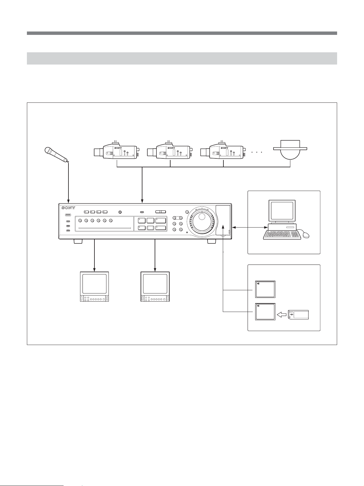
System Configuration Example
You can record images captured by the connected
cameras while observing the input on the video
monitor, and play back the recorded images.
Microphone
VIDEO
OUT
Video cameras (max. 6 units)
Network connection
MIC
POWER
ALARM
ALARM FULL
FULL
DIGITAL SURVEILLANCE RECORDER HSR-X206
Main monitor
MONITOR 2
OSDQUADMULTI
4321
65
ALARM RESET
INPUT SELECTOR
MONITOR/MON 1
VIDEO
IN
IN 1 - 6
-
l
LOCK
PRE REVERSE PLAY
S PAUSE s STOP G PLAY
REC
TIMER
STOP
MONITOR/MON 2
VIDEO
IN
Submonitor
HSR-X206/X206P
SHUTTLE
MENU
ZOOM
SEQUENCE COPY
SEARCH
HOLD
U
T
EXIT
E
R
J
j
N
R
E
N
T
E
R
LAN
PUSH
ALARM
L
a REC
Computer
Data storage
Compact Flash card
Memory Stick
CF card adaptor
7
Locations and Functions of Parts
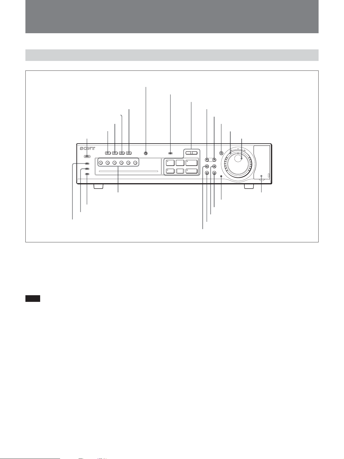
Front Panel
6 ALARM RESET button
7 LOCK indicator
8 Record/Playback buttons
5 MONITOR 2 button and indicator
4 OSD button and Indicator
3 QUAD button and indicator
2 MULTI button and indicator
1 POWER indicator
9 MENU button
q; EXIT button
qa SHUTTLE HOLD button and indicator
qs Shuttle dial
qd Jog dial
OSD
MONITOR 2
POWER
ALARM
ALARM FULL
FULL
QUADMULTI
DIGITAL SURVEILLANCE RECORDER HSR-X206
4321
ALARM RESET
65
INPUT SELECTOR
qj INPUT SELECTOR buttons
and indicators
qh FULL indicator
qg ALARM FULL indicator
qf ALARM indicator
1 POWER indicator
Lights in green when the power is applied to the unit
and goes dark when the power is disconnected.
It flashes in red if any problem occurs with the harddisk drive or fan.
Note
In order to keep the unit internal temperature low, a
fan is provided on the side of the unit. If the fan does
not operate properly, the POWER indicator will flash
to indicate a problem. Unplug the unit from the power
supply and check to make sure nothing is obstructing
the fan. If after the power is restored to the unit, the
POWER indicator still flashes, do not use the unit and
consult your dealer.
2 MULTI (Multi screen) button and indicator
When you press this button, the monitor changes to
6-division screen display.
3 QUAD (4-division screen) button and indicator
When you press this button, the monitor enters 4division mode. With each subsequent press of this
button, the next 4 pictures are displayed.
8
MENU
ZOOM
SEARCH
SEQUENCE COPY
SHUTTLE
HOLD
j
N
R
U
T
OSD
E
R
J
E
N
T
E
R
PUSH
-
l
REC
STOP
ALARM
PRE REVERSE PLAY
a REC
LOCK
S PAUSE s STOP G PLAY
TIMER
L
wd CF card slot
ws Menu reset button
wa COPY button and indicator
w; SEARCH button
ql SEQUENCE button and indicator
qk ZOOM button and indicator
4 OSD button and indicator
Each time you press the button, the position of the onscreen data will change in sequence of bottom, no
display, and top (default: top).
For details on the on-screen data, see “On-screen Data” on
page 13.
5 MONITOR 2 button and indicator
When you press this button, the indicator lights, and
the unit enters Setup mode for the submonitor
connected to the MONITOR/MON 2 connector.
When you press the button again, Submonitor Setup
mode is released.
6 ALARM RESET button
When you press this button in alarm status, the alarm
indications are all reset.
7 LOCK indicator
Lights in red when the security lock function is active.
When you press an operation button with this indicator
lit, the indicator flashes, and a message is displayed to
prompt you to enter a password.
For details on the security lock and password, see “Security
Lock Settings” on page 63.
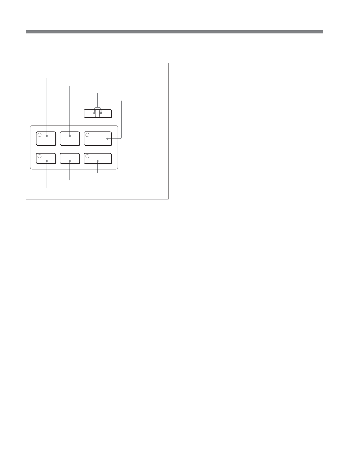
8 Record/Playback buttons
A X PAUSE button and indicator
B x STOP button
C . ALARM > skip buttons
ALARM
l
PRE REVERSE PLAY
S PAUSE s STOP G PLAY
L
D B PLAY/PRE
REVERSE PLAY
button and
indicator
E TIMER button and indicator (red)
When you press this button, the unit enters timerstandby status, and the indicator lights. Recording will
begin at the starting time you specified using the
menu, and the REC button indicator will light.
Pressing the button again cancels timer-standby status
or timer recording in progress.
For details on the operation, see “Timer Recording” on
page 37.
F REC STOP button
Press this button to end recording.
TIMER
E TIMER button and indicator
REC
STOP
F REC STOP button
a REC
G z REC button and indicator
A X PAUSE button and indicator (amber)
When you press this button during playback or while
monitoring a camera input, the unit enters Still-Picture
mode, and the indicator lights.
Press the button again to restore the previous mode.
B x STOP button
Press this button to end playback (including that of
Still-Picture or Variable-Speed Playback mode).
C . ALARM > skip buttons
During playback of an alarm recording event, pressing
. skips to the previous alarm recording event, and
pressing > skips to the next alarm recording event.
During playback of an event in the archive area,
pressing . skips to the previous event, and pressing
> skips to the next event.
D B PLAY/PRE REVERSE PLAY button and
indicator (green)
When you press this button in stop status, the indicator
lights, and playback begins.
For details, see “Normal Playback” on page 43.
By pressing the button during recording, you can view
the recorded images from the point before the
specified pre-reverse time (1 to 99 minutes) without
stopping the recording in progress (Pre-Reverse
Playback).
For details on the operation, see “Pre-Reverse Playback–
Playback During Recording” on page 44.
G z REC button and indicator (red)
When you press this button, the indicator lights, and
recording begins.
9 MENU button
When you press this button, the unit enters Menu
mode.
In Menu mode, you can switch the submenus
or the
menu items in sequence.
For details on the operation, see “Menu Operations” on
page 14.
0 EXIT button
Press to quit Menu mode.
When the recorder is connected to a network, the
connection can be terminated by holding this button
pressed.
qa SHUTTLE HOLD button and indicator (green)
By pressing this button to light the indicator, you can
lock the direction and speed of playback dictated by
the current orientation of the Shuttle dial.
When you press the button again, the mode before you
start the variable-speed playback will be restored.
For details on the operation, see “Variable-Speed
Playback” on page 44.
qs Shuttle dial (outer)
When you rotate the Shuttle dial in Playback mode
(PLAY button indicator lit) or in Still-Picture mode
(PAUSE button indicator lit), playback is performed
according to the direction and degree of the rotation.
For details on the operation, see “Variable-Speed
Playback” on page 44.
In OSD operations, your selection or setting will be
accepted when you turn the dial clockwise.
9

Locations and Functions of Parts
qd Jog dial (inner)
By rotating the Jog dial in Playback mode (PLAY
button indicator lit), you can gradually change the
playback speed. Clockwise rotation increases the
speed and counterclockwise rotation decreases it.
When you rotate the Jog dial in Still-Picture mode
(PAUSE button indicator lit), playback is performed
frame by frame. Clockwise rotation forwards the
frames and counterclockwise rotation reverses them.
For details on the operation, see “Variable-Speed
Playback” on page 44.
In OSD operations, you can move the cursor on the
screen and select setting values using this dial.
qf ALARM indicator
Lights in red during pre-alarm recording and flashes in
red during alarm recording. It goes dark when
recording ends.
For alarm recording and pre-alarm recording, see “Alarm
Recording” on page 32.
qg ALARM FULL indicator
Flashes in red if the remaining capacity of the alarm
recording area of the built-in hard disk drops below the
specified value (default: 1%), and steadily lights in red
if the remaining capacity becomes 0.
qh FULL indicator
Flashes in red if the remaining capacity of the normal
recording area of the built-in hard disk drops below the
specified value (default: 1%), and steadily lights in red
if the remaining capacity becomes 0.
qj INPUT SELECTOR buttons and indicators
When you press one of these buttons, the indicator on
that button lights, and the picture from the camera
connected to the corresponding camera input is
displayed on the monitor.
The indicator of the camera whose alarm is activated
flashes.
ql SEQUENCE (automatic switching) button and
indicator
When you press this button, the indicator begins to
flash, and the unit enters Automatic Switching mode.
In Full-Screen mode, pictures from cameras connected
to the camera connectors will be automatically
displayed one by one in sequence.
In 4-division mode, all 4 pictures on the screen will be
switched to the next 4 pictures at a time.
This button is invalid in Multi-Screen mode.
The switching interval can be set by menu operation.
w; SEARCH button
When you press this button in a recording mode or in
stop status, the search operation display appears.
wa COPY button and indicator (green)
Press this button to copy the data to the archive area of
the built-in hard disk or external memory devices. The
indicator lights, and the copy-operation display
appears.
For details on the operation, see “Data Storage” on page
40.
ws Menu reset button
Press this button to return the settings of the menu
items being displayed on the monitor to the factory-set
default settings.
wd CF card slot
If you insert a Compact Flash card, copying of the
recorded data to external memory will be enabled.
When you use a commercially available CF card
adaptor (Compact Flash Type II), copying of the data
to Memory Sticks, etc. will be enabled.
qk ZOOM button and indicator (green)
The button permits you to zoom in on a part of the
camera input or playback image on the monitor screen.
Specify the part to be zoomed in using the Jog and
Shuttle dials.
While the zoom function is active, the indicator of the
ZOOM button lights. When you press the button
again, the normal size is restored.
For details on the operation, see “Zooming in on a detail of
a picture” on page 18.
10
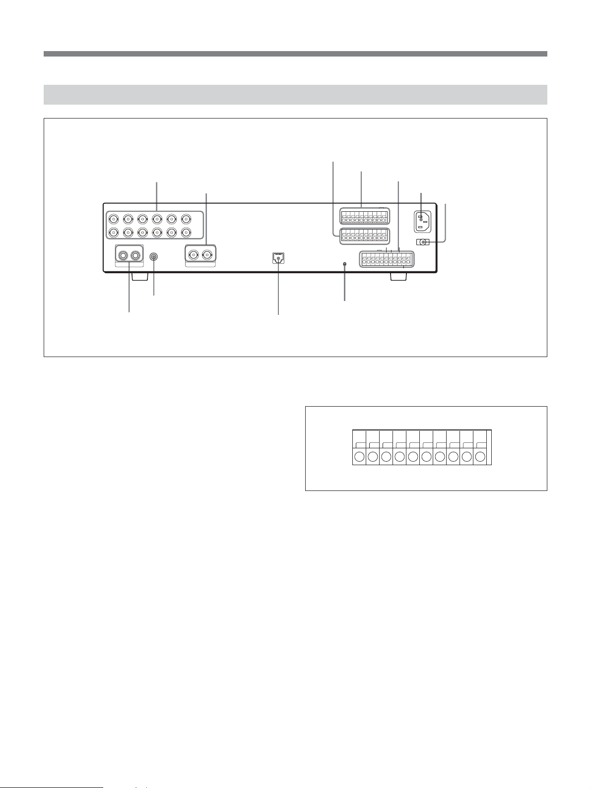
Rear Panel
IN
1 Camera connectors
OUT
MIC
AUDIO
2 MONITOR connectors
654321
IN
OUT
MON 1 MON 2
MONITOR
5 SENSOR ALARM OUT and control terminals
6 ALARM IN and control terminals
7 Control terminals
8 -AC IN connector
ALARM
ALARM IN
RESET FULL
-
ALARM
OUT
NON REC EXT TIMER
CLOCK
OUT
WARNING
AC IN
FULL
C
C 123456C
LAN
SENSOR ALARM OUT
ALL RESET
CR1R2IN
9 Power cord holder
4 MIC connector
3 AUDIO connectors
0 LAN connector
1 Camera connectors (BNC type)
IN: Connect video cameras.
OUT: The camera signals supplied to the
corresponding IN connectors are output as-is.
2 MONITOR connectors (BNC type)
MON 1 (main monitor): To output a video signal to
the main monitor. Connect to the video input of
the monitor.
MON 2 (submonitor) : To output a video signal to the
submonitor. Connect to the video input of the
monitor. Only the live picture is output. No
playback picture is output.
3 AUDIO connectors (phono jacks)
IN: Connect an audio signal. When a microphone is
connected to the MIC connector, the microphone
input takes priority.
OUT: Connect to the AUDIO IN connector of a
monitor.
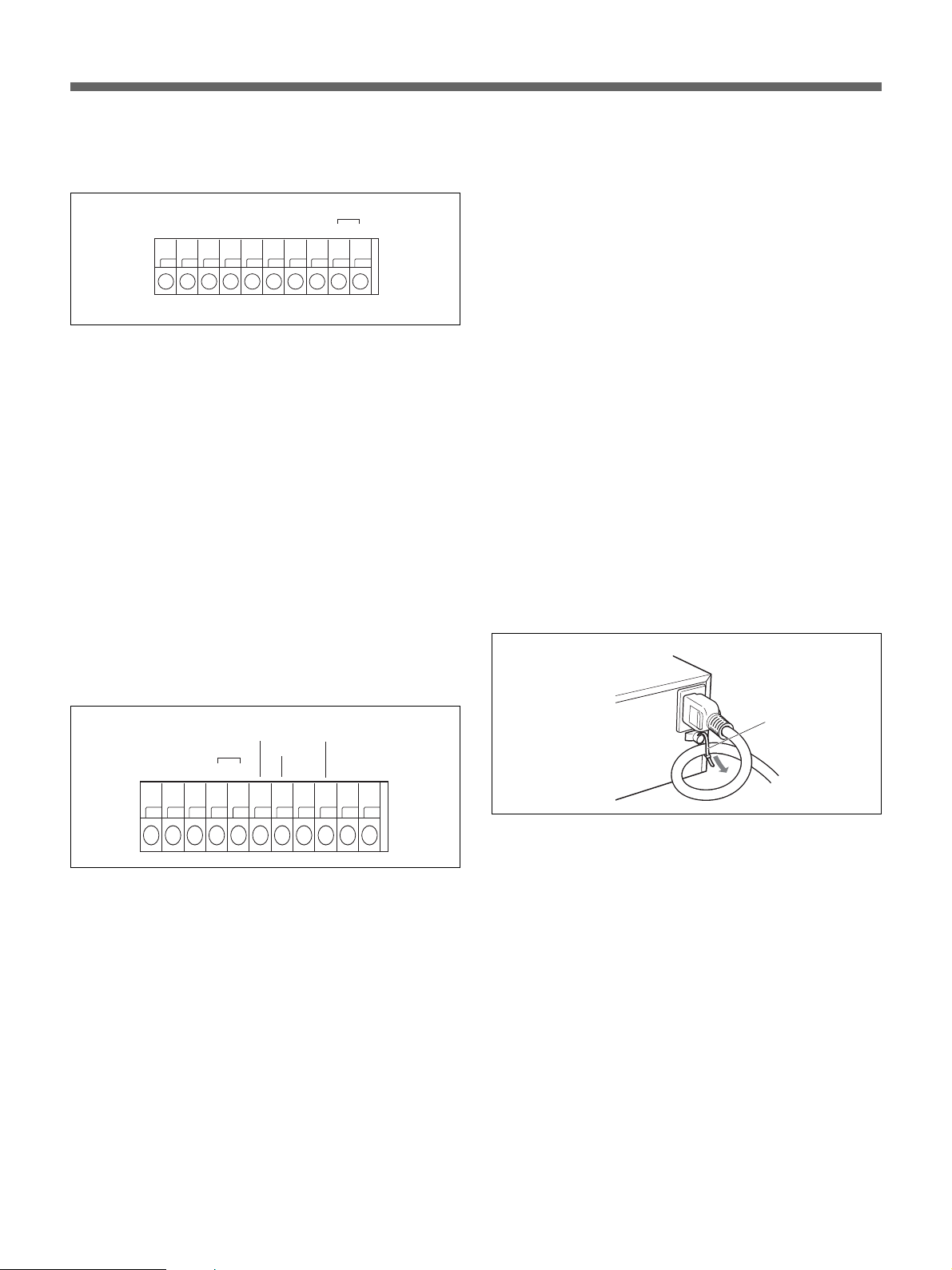
qa ALL RESET button
5 SENSOR ALARM OUT and control terminals
The C terminals are for ground.
C123
456
C
ALARM
C
OUT
1 to 6 terminals
When the sensor alarm of a channel activates, an alarm
signal is output from the corresponding terminal.
For details, see “Outputting alarm signals” on page 52.
ALARM OUT terminal (5V DC/5.7 kΩ)
The output level drops to 0 V when the built-in activity
detection sensor operates or an external alarm is
detected.
4 MIC (microphone) connector (monaural
minijack)
Connect a microphone for audio recording.
11
Locations and Functions of Parts
6 ALARM IN and control terminals
The C terminals are for ground.
ALARM
RESET FULL
C12 3
456
C
1 to 6 terminals
Connect alarm sensors to receive external alarm
signals.
For details, see “Connecting external alarm sensors” on
page 53.
ALARM RESET terminal
Alarm reset input (normally-open contact)
ALARM FULL terminal (5V DC/5.7 kΩ)
The output level drops to 0 V if the remaining capacity
of the alarm recording area of the built-in hard disk
drops below the specified value.
NON REC terminal (5V DC/5.7 kΩ)
The output level drops to 0 V if recording is
interrupted.
WARNING terminal (5V DC/5.7 kΩ)
The output level drops to 0 V if any problem occurs
with the HDD.
FULL terminal (5V DC/5.7 kΩ)
The output level drops to 0 V if the remaining capacity
of the normal recording area of the built-in hard disk
drops below the specified value (default: 1%).
EXT TIMER terminal
When External Timer Recording mode has been
specified, recording starts upon reception of a signal at
this terminal (normally-open contact).
8 -AC IN connector
Connect AC power using the supplied AC power cord.
9 Power cord holder
Secure the AC power cord using the supplied tie, as
shown below.
7 Control terminals
For input and output of various control signals.
The C terminals are for ground.
CLOCK
CR1R2IN
OUT
NON REC
EXT TIMER
WARNING
FULL
NC
C
R1/R2 terminals (resistor-alley system)
For remote control.
For the connections, see “Connections for Remote Control”
on page 56.
CLOCK terminals
You may adjust the built-in clock using an external
switch or synchronize the clocks of other connected
devices to the clock of this unit.
IN: Clock input (normally-open contact). Connect an
external switch or equivalent.
OUT: Clock output (5V DC/5.7 kΩ). The output level
drops to 0 V at the time you specified by menu
operation.
Tie
0 LAN connector (10Base-T/100Base-TX)
Used to control this unit via a network.
qa ALL RESET button
For reset or reboot of the HSR-X206/X206P.
For the connection, see “Clock Adjustment” on page 57.
12
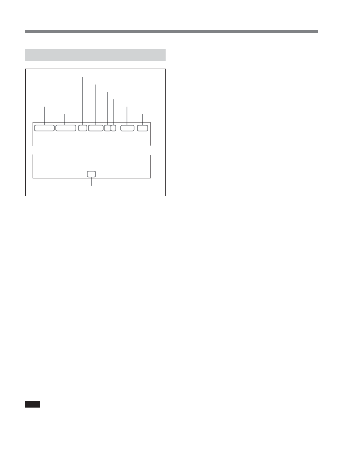
On-Screen Data
4 Remaining of recording area
When the recording area OVERWRITE function is set
to OFF with the RECORDING CONDITIONS SET
3 Operation status
4 Remaining of recording area
5 Picture quality
6 Audio recording
1 Date
2 Time
03-01-01 00:00:00 REC REPEAT HI A ALARM 0000
7 Alarm type
8 Alarm
count
menu
area is displayed (in %).
5 Picture quality
In a recording mode or stop status, the picture quality
and recording cycle specified for normal recording are
displayed.
In playback, the picture quality and recording cycle
when the recording has made are displayed.
6 Audio recording
During audio recording, “A” is displayed.
(page 61), the remaining capacity of the recording
02
9 Camera title
By pressing the OSD button on the front panel, you
can change the display position or even make them
disappear.
Items except the operation status can be independently
turned on/off with a menu operation
1 Date/2 Time
In a recording mode or stop status (monitoring the
camera input), the current date (month-day-year on the
HSR-X206 or day-month-year on the HSR-X206P)
and time (hour:min:sec) are displayed.
In playback, the date and time when the recording has
made are displayed.
3 Operation status
The current operation mode is displayed.
REC: Recording
EXT: External timer recording
B: Playback in the forward direction
b: Playback in the reverse direction
X: Still
M: High-speed playback in the forward direction
m: High-speed playback in the reverse direction
C: Slow-motion playback in the forward direction
c: Slow-motion playback in the reverse direction
Note
When recording and playback are both in progress,
only B is displayed.
7 Alarm type
The active alarm type is displayed.
ALARM: Alarm recording
PRE: Pre-alarm recording
The indication flashes while the corresponding
recording is in progress.
8 Alarm count
Each time alarm recording is made, the value is
increased by one.
The value will return to 1 if it exceeds 9999.
9 Camera title
The number (or title if defined) of the camera being
selected is displayed.
When an alarm is generated, “EA (external alarm)” or
“SA (sensor alarm)” flashes at the left of the number
(title).
Disk error indication
If an error has occurred on a hard disk, one of the
following error message will appear at the center of the
screen:
DISK ERROR: An error has occurred, but it cannot
be determined on which of the two disks it has
occurred.
DISK ERROR(1): An error has occurred on DISK1
(MASTER).
DISK ERROR(2): An error has occurred on DISK2
(SLAVE).
DISK ERROR(1->2): An error has occurred on
DISK1 then on DISK2.
DISK ERROR(2->1): An error has occurred on
DISK2 then on DISK1.
13
Basic OSD Operations
You can perform various settings on the monitor
screen.
For the on-screen displays, you can select from among
English, French, Spanish and German (HSR-X206P only)
with a menu operation. See page 57.
For the menu layers, see page 16.
The display examples in this manual are those for the
HSR-X206P.
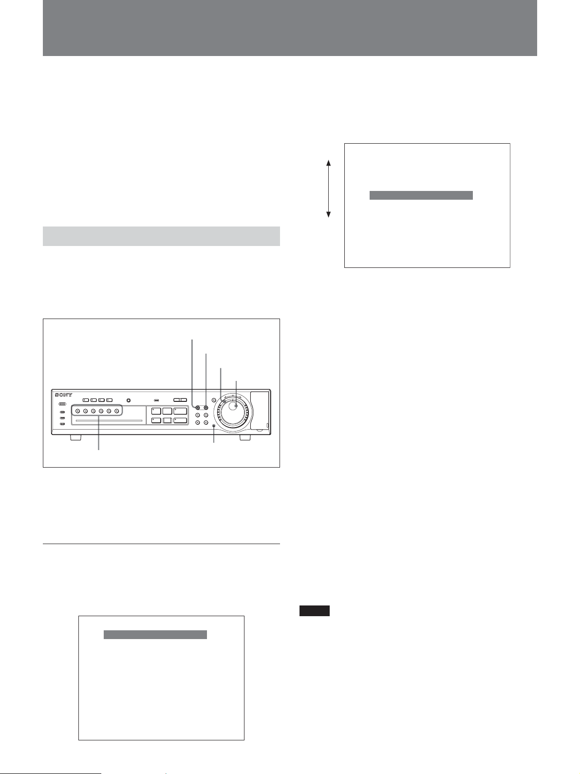
Menu Operations
This section describes how to set a menu item as an
example of OSD (On-Screen Display) operations.
Buttons and dials used in menu operations
MENU button
EXIT button
Shuttle dial
Jog dial
POWER
ALARM
ALARM FULL
FULL
QUADMULTI
DIGITAL SURVEILLANCE RECORDER HSR-X206
INPUT SELECTOR buttons
ALARM RESET
INPUT SELECTOR
-
l
LOCK
PRE REVERSE PLAY
S PAUSE s STOP G PLAY
REC
TIMER
STOP
ALARM
a REC
MONITOR 2
OSD
65
4321
SHUTTLE
HOLD
L
MENU
EXIT
ZOOM
SEARCH
SEQUENCE COPY
Menu reset button
J
j
E
N
N
T
R
E
U
T
E
R
R
PUSH
To move the highlighting
Turn the Jog dial. Clockwise rotation moves the menu
bar downward and counterclockwise rotation moves it
upward.
Counterclockwise
Clockwise
<MAIN MENU>
1. INITIAL SET c
2. RECORD SET c
3. GENERAL SET c
4. SCREEN SET c
5. POWER LOSS/USED TIME c
6. INITIALIZATION LOG c
7. COPY MENU SETTINGS c
MOVE LINES WITH JOG, SELECT WITH SHUTTLE
To select a menu item
Move the menu bar to highlight the desired item using
the Jog dial, then turn the Shuttle dial clockwise to
register your selection.
When you select 1. INITIAL SET, 2. RECORD SET,
3. GENERAL SET, or 4. SCREEN SET, the
corresponding submenu appears.
When you select 5. POWER LOSS/USED TIME,
6. INITIALIZATION LOG, or 7. COPY MENU
SETTINGS, the information/setting display appears.
To return to the main menu from a submenu
or a setting display
Turn the Shuttle dial counterclockwise.
The SEARCH and COPY buttons also associate their
own menus.
For these menus, see page 46 or see page 40.
Starting a menu operation
Press the MENU button. The main menu appears on
the monitor screen.
The menu bar highlights the top item.
<MAIN MENU>
1. INITIAL SET c
2. RECORD SET c
3. GENERAL SET c
4. SCREEN SET c
5. POWER LOSS/USED TIME c
6. INITIALIZATION LOG c
7. COPY MENU SETTINGS c
MOVE LINES WITH JOG, SELECT WITH SHUTTLE
14
To switch to a submenu or a setting display of
another menu item
Press the MENU button when a submenu or a setting
display of a menu item is displayed.
A submenu or a setting display of the next menu item
appears.
For example, when you press the MENU button while
the submenu of 1. INITIAL SET is displayed, the
submenu of 2. RECORD SET appears.
Notes
• Any menu display does not appear during playback,
even if you press the MENU button.
• When you press the MENU button during recording,
a menu display appears, and you can check the menu
settings. In this case, the z (record) mark is
displayed in the upper left part of the menu screen,
and you cannot change the settings. To set a menu
item, first stop recording.
Setting an item
1 When setting the highlighted item, simply turn the
Shuttle dial clockwise.
The current setting begins to flash.
<LANGUAGE/LANGUE/SPRACHE/IDIOMA>
ENGLISH
<CLOCK SET>
01-01-2004 THU 09:01:00
<SUMMER TIME SET>
MODE : NO USE
WEEK MONTH TIME
ON LST-SUN O3 02:00
0FF LST-SUN 10 02:00
<EXT. CLOCK SET>
ADJUST. TIME : 01:00
<LANGUAGE/LANGUE/SPRACHE/IDIOMA>
ENGLISH
<CLOCK SET>
01-01-2004 THU 09:01:00
<SUMMER TIME SET>
MODE : NO USE
WEEK MONTH TIME
ON LST-SUN O3 02:00
0FF LST-SUN 10 02:00
<EXT. CLOCK SET>
ADJUST. TIME : 01:00
<LANGUAGE/LANGUE/SPRACHE/IDIOMA>
ENGLISH
<CLOCK SET>
01-01-2004 THU 09:01:00
<SUMMER TIME SET>
MODE : NO USE
WEEK MONTH TIME
ON LST-SUN O3 02:00
0FF LST-SUN 10 02:00
<EXT. CLOCK SET>
ADJUST. TIME : 01:00
2 To change the setting at the flashing line or
column, turn the Jog dial.
The values (settings) you can select for the flashing
line or column are displayed in sequence.
3 When the desired value (setting) is displayed, turn
the Shuttle dial clockwise to register the new value
(setting).
The next column, if any on the same line, starts
flashing. Set it in the same manner.
By turning the Shuttle dial counterclockwise, you can
reverse the setting procedure.
When the setting(s) on one line ends, the next line you
can set will be highlighted when you turn the Shuttle
dial clockwise.
Or, select the item to be set by moving the
highlighting with the Jog dial, and turn the Shuttle
dial clockwise to finalize your selection.
On the line where multiple inputs are required, the
first column begins to flash.
<LANGUAGE/LANGUE/SPRACHE/IDIOMA>
ENGLISH
<CLOCK SET>
01-01-2004 THU 09:01:00
<SUMMER TIME SET>
MODE : NO USE
WEEK MONTH TIME
ON LST-SUN O3 02:00
0FF LST-SUN 10 02:00
<EXT. CLOCK SET>
ADJUST. TIME : 01:00
To return the settings to the defaults
Press the Menu Reset button on the front panel using a
thin pointed implement.
All the settings of the menu item being displayed on
the monitor screen will return to their factory-set
values.
To exit Menu mode
Press the EXIT button.
Storing the menu settings
The values set with the menus can be stored on a
Compact Flash as data and loaded to resume the
settings when required.
For the operation, see “Saving/Loading of Menu Settings”
on page 54.
15

Basic OSD Operations
Menu Layers
MAIN MENU Submenu Setting items Setting values or functions
1. INITIAL SET 1. LANGUAGE/CLOCK SET LANGUAGE ENGLISH/FRANÇAIS/DEUTSCH
CLOCK SET
SUMMER TIME SET
EXT. CLOCK SET
2. CAMERA DETECT – Detects the connected cameras.
3. TITLE SET CAMERA 1 - 6 10-digit camera titles
4. HOLIDAY SET 1 - 20
5. TIME PERIOD SET TIME PERIOD A T-1/T-2/T-3/T-4,
TIME PERIOD B T-1/T-2/T-3/T-4,
SELECT TIME PERIOD SEQUENCE A/B, MASK A/B, ACTIVITY SENSOR A/B
6. PRE-REVERSE PRE-REVERSE PLAY TIMEn MIN (n = 1 - 99)
2. RECORD SET 1. NORMAL REC EASY SET RECORDING DURATION BASE (RECORDING DURATION, TIMER RECORDING,
PICTURE QUALITY, AUDIO RECORDING)
REC RATE BASE (REC RATE, TIMER RECORDING, PICTURE QUALITY, AUDIO
RECORDING)
2. RECORDING AREA SET NORMAL RECORDING AREAn %, AREA FULL RESET
ALARM RECORDING AREAn %, AREA FULL RESET
ARCHIVE AREA
3. RECORDING CONDITIONS NORMAL RECORDING AREA OVERWRITE ON/OFF
SET ALARM RECORDING AREA OVERWRITE ON/OFF
REMAINING DISK WARNINGn % (n = 1 - 10)
AUTO DELETE 1 - 99 DAYS
4. NORMAL REC MODE SET PICTURE QUALITY HYPER/SUPER/HIGH/MID/LOW
AUDIO RECORDING ON/OFF
REC RATE
REC PROGRAM GROUP OFF/P-1/P-2/P-3/P-4
5. PROGRAM REC SET P-1/P-2/P-3/P-4
6. TIMER SET WEEK SUN/MON/TUE/WED/THU/FRI/SAT/DLY/EXT
START
STOP
PROGRAM OFF/P-1/P-2/P-3/P-4
FPS
7. ALARM REC MODE SET ALARM RECORDING ENABLED/AL-REC ON TIMER/AL-REC OFF TIMER/
PICTURE QUALITY HYPER/SUPER/HIGH/MID/LOW
AUDIO RECORDING ON/OFF
ALARM INTERLEAVE ONLY/SW
REC RATE
DURATION 5S/10S/20S/40S/1M/2M/3M/4M/5M/10M/15M/CC
PRE-ALARM RECORDING ON/OFF
REC RATE
DURATION 5S/10S/20S/40S/1M/2M/3M/4M/5M/10M/15M
ALARM TRIGGER ALARM/SENSOR/ALARM AND SENSOR/
ACTIVITY SENSOR to the Activity Detection Sensor Set display
8. ALARM OPERATION SET ALARM RETRIGGER ON/OFF
MAIN MON DISPLAY FULL/6/NC
ALARM PRIORITY LAST/FIRST/SWITCH
MON.2 DISPLAY ON/OFF
1) HSR-X206P only
2)
mm-dd
with HSR-X206
3)
3) DAYLIGHT SAVINGS with HSR-X206
2)
dd-mm
USE/NO USE
ON WEEK/MONTH/TIME
OFF WEEK/MONTH/TIME
-yyyy/hh:mm:ss
hh-mm
2)
dd-mm
hh-mm
hh-mm
n
%(n = 1 -10), AREA FULL RESET
n
FPS
n
FPS
hh:mm
hh:mm
n
FPS
OLY AL-RC ON TMR/OFF
n
FPS
n
FPS
ALARM OR SENSOR
1)
/ESPAÑOL
16

MAIN MENU Submenu Setting items Setting values or functions
3. GENERAL SET 1. DISPLAY SET DATE ON/OFF
TIME ON/OFF
QUALITY ON/OFF
AUDIO ON/OFF
ALARM COUNT ON/OFF
ALARM TYPE ON/OFF
TITLE ON/OFF
VIDEO LOSS ON/OFF
2. BUZZER SET ALARM ON/OFF
DISK FULL ON/OFF
DISK ERROR ON/OFF
LOCK WARNING ON/OFF
KEY IN ON/OFF
NON REC ON/OFF
3. SECURITY LOCK SET ADMIN PASSWORD, USE ON/OFF
USER PASSWORD, USE ON/OFF
REC CONTROL ADMIN/USER
4. HDD SET DISK INITIALIZE Initializes a hard disk.
MIRRORING ON/OFF
PLAYBACK DRIVE DISK1/DISK2
5. NETWORK SET NETWORK CONTROL ON (NETWORK)/ON (DVR)/OFF
NETWORK STATUS ON/OFF
IP ADDRESS To be specified according to your system.
SUBNET MASK
GATEWAY
PORT 1–65535
PASSWORD ID1/ ID2/ID3 4 to 8 characters
4. SCREEN SET 1. MULTI SCREEN NORMAL/CHANGE
QUAD POSITION SET to QUAD POSITION SET MENU
MULTI 6 POSITION SET to MULTI 6 POSITION SET MENU
2. SEQUENCE SET FULL: n SEC/ QUAD: n SEC
MAIN/MON.2 MONITOR SET
3. MASK ON/OFF
MASK SET to the MASK SET display
4. COLOR LEVEL SET 1 - 10/AUTO
5. POWER LOSS/USED TIME POWER LOSS Display only
USED TIME
FIRMWARE
6. INITIALIZATION LOG DATE, AREA Display only
7. COPY MENU SETTINGS SAVE MENUS TO CF Saves the menu settings.
LOAD MENUS FROM CF
COPY RECORDING AREA YES/NO
SETTINGS
ON/OFF
Loads the menu settings.
17

Live Picture Monitoring
You can watch live pictures from cameras by
displaying them on the main monitor (MONITOR 1)
and/or the sub monitor (MONITOR 2).
The main monitor and the sub monitor can be set
individually, so you can watch a live picture on the sub
monitor, while the main monitor is in playback mode.
Buttons used for live picture monitoring
MULTI button
QUAD button
MONITOR 2 button
MONITOR 2
OSD
POWER
ALARM
ALARM FULL
FULL
QUADMULTI
65
4321
DIGITAL SURVEILLANCE RECORDER HSR-X206
INPUT SELECTOR buttons
ALARM RESET
INPUT SELECTOR
-
l
LOCK
PRE REVERSE PLAY
S PAUSE s STOP G PLAY
REC
TIMER
STOP
ALARM
a REC
ZOOM button
SHUTTLE
HOLD
L
MENU
ZOOM
SEQUENCE COPY
j
N
R
U
T
EXIT
E
R
SEARCH
SEQUENCE button
J
E
N
T
E
R
PUSH
Switching the display automatically
Press the SEQUENCE button so that the indicator
lights.
The pictures are automatically displayed in sequence at
regular intervals (1 to 30 sec.). To cancel the
automatic switching operation, press the SEQUENCE
button again or press one of the INPUT SELECTOR
buttons so that the SEQUENCE indicator goes dark.
The switching interval can be specified in a menu
operation.
For the interval setting procedure, see “Specifying the
automatic switching interval” on page 21.
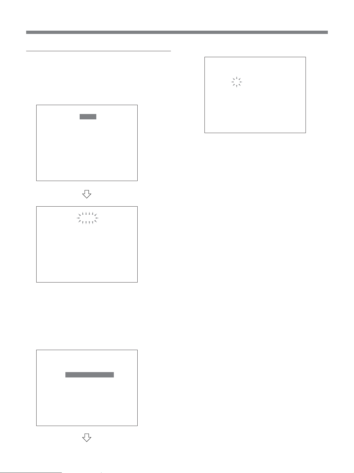
Zooming in on a detail of a picture
In full-screen mode, you can zoom in on a detail of a
picture by pressing the ZOOM button.
1 Press the INPUT SELECTOR button
corresponding to the camera to be monitored and
display the picture full-screen.
Observing the Live Picture from a Particular Camera (Full-Screen Mode)
Press the INPUT SELECTOR button of the camera
whose picture is to be displayed.
The indicator of that button lights, and the picture from
the camera you chose is displayed full-screen.
Pressing the same button again restores the previous
mode.
To change the display on the submonitor
(MONITOR 2)
After pressing the MONITOR 2 button to light the
indicator, press the INPUT SELECTOR button
corresponding to the camera you wish to check. You
can watch the desired camera picture independently of
the main monitor.
To change the main monitor display, press the
MONITOR 2 button again so that the indicator goes
dark.
2 Press the ZOOM button.
A frame to specify the zoom-in area appears
centered on the screen.
3 Move the frame horizontally to the desired zoom-
in area using the Jog dial, then turn the Shuttle dial
clockwise to register the horizontal position.
4 Move the frame vertically to the desired zoom-in
area using the Jog dial, then turn the Shuttle dial
clockwise to register the vertical position.
18
01
02
03
04
01
01
02
03
04
05
01
02
06
08
07
09
03
07
01 02
02
05
05 06
The image of the specified area is enlarged and
displayed full-screen.
To cancel Zoom mode
Press the ZOOM button again.
When one of the other INPUT SELECTOR buttons is
pressed, the picture of the corresponding camera is
displayed in Normal mode.
When another mode button, such as the QUAD button
or the MULTI button, is pressed, the unit is switched
to the corresponding mode.
03 04
03
01
04
01 02
02
The indicators of the INPUT SELECTOR buttons
corresponding to the camera inputs displayed light.
You can change the combination of the 4 camera
inputs to be displayed simultaneously and the position
of the pictures on the screen by menu operation.
For the setting procedure, see “Changing the position of
pictures on a divided screen”on page 20.
To switch the display automatically
Press the SEQUENCE button so that the indicator
lights.
The four pictures displayed are automatically switched
to the next 4 pictures in sequence at regular intervals
(1 to 30 seconds).
To cancel the automatic switching operation, press the
SEQUENCE button again so that the indicator goes
dark.
The switching interval can be specified by menu
operation.
For the interval setting procedure, see “Specifying the
automatic switching interval” on page 21.
Monitoring Multiple Cameras Simultaneously (Divided Screen)
You can monitor multiple cameras simultaneously by
displaying a divided screen.
Switching to 4-division mode
Press the QUAD button.
The pictures from 4 cameras are displayed
simultaneously on the screen.
01
01 02
03 04
03
With each subsequent press of the QUAD button, the
next 4 pictures are displayed.
02
04
Note
The display cannot be automatically switched in
Playback mode.
Switching to 6-division mode
Press the MULTI button.
The pictures from up to 6 cameras are displayed
simultaneously on the screen.
02
03
01
07
0504 06
07
08
You can change the position of the pictures by menu
operation.
For the setting procedure, see “Changing the position of
pictures on a divided screen” on page 20.
06
03
09
19

Live Picture Monitoring
Setting the Display Conditions
You can specify the various conditions of the screen
display of the monitor by selecting 4. SCREEN SET
from the main menu.
SCREEN SET display
<SCREEN SET>
1. MULTI SCREEN : NORMAL
QUAD POSITION SET c
MULTI 6 POSITION SET c
2. SEQUENCE SET
FULL : 1S QUAD : 1S
MAIN/MON. 2 MONITOR SET c
3. MASK : OFF
MASK SET c
4. COLOR LEVEL SET c
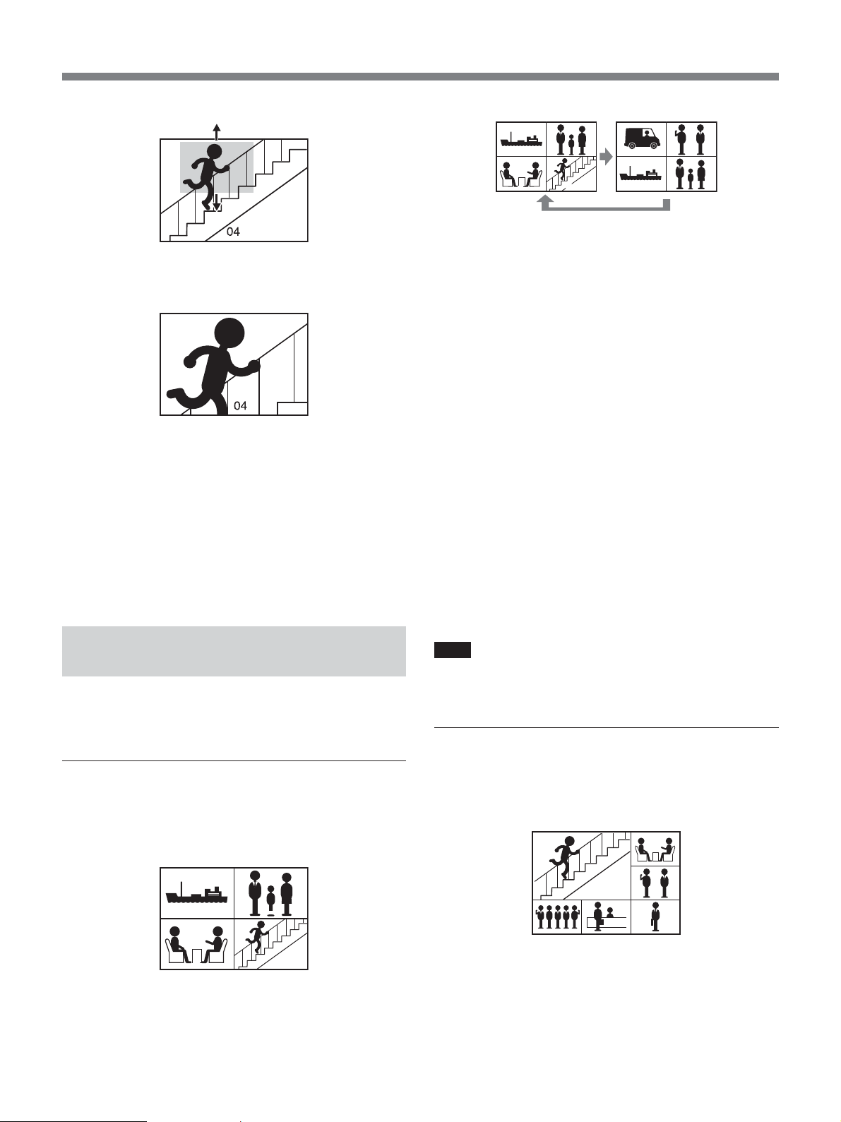
Changing the position of pictures on a
divided screen
Specify the display position and the combination of
camera inputs to be displayed simultaneously in 4divison mode or the position of pictures on 6-division
mode with 1. MULTI SCREEN.
NORMAL: From the upper-left position to the
lower-right position camera pictures are displayed
in the order of camera number. Any position with
no camera input is displayed in gray.
CHANGE: The position for each camera input can
be set in the desired order.
<QUAD POSITION SET MENU>
QUAD1 QUAD2
01 02 05 06
03 04 01 02
CHECK THE SCREEN 1 c
CHECK THE SCREEN 2 c
To set 6-screen display, move the cursor to
MULTI POSITION SET, then turn the Shuttle dial
clockwise.
The MULTI 6 POSITION SET MENU appears.
<MULTI 6 POSITION SET MENU>
MULTI 6
01 02
03
04 05 06
CHECK THE SCREEN c
3 On the QUAD POSITION SET MENU, specify
the 2 combinations of 4 camera inputs to be
switched by the QUAD button by entering the
desired camera numbers for the 4 tiled picture
positions.
Setting procedure:
1 Select CHANGE for 1. MULTI SCREEN, then
turn the Shuttle dial clockwise.
2 To set 4-screen display, move the cursor to
QUAD POSITION SET, then turn the Shuttle dial
clockwise.
The QUAD POSITION SET MENU appears.
20
On the MULTI 6 POSITION SET MENU,
specify the desired camera number for each of the
6 tiled picture positions.
1) Turn the Jog dial to move the cursor to one of
the picture positions, then turn the Shuttle dial
clockwise so that the camera number presently
set flashes.
2) Change the setting using the INPUT
SELECTOR buttons or the Jog dial, then
register the new setting using the Shuttle dial.
Repeat steps 1) and 2) for each picture positions.

To check your settings
Move the cursor to SCREEN CHECK, then turn the
Shuttle dial clockwise. The tiled screen with the
camera combination you set is displayed.
To return to the SCREEN SET display, turn the
Shuttle dial counterclockwise.
When the settings are completed
Press the EXIT button to exit the menu.
Specifying the automatic switching
interval
You can specify the interval of the automatic
switching operation with the SEQUENCE button by
setting 2. SEQUENCE SET of the the SCREEN SET
display.
The MAIN/MON.2 MONITOR SET menu
appears.
MAIN MONITOR SET display
<MAIN/MON. 2 MONITOR SET>
TIME PERIOD : T-1 (09:00 - 12:00)
CH 01 02 03 04 05 06
MAIN MON. ON ON ON ON ON ON
MON. 2 ON ON ON ON ON ON
2 Select the time period (T-1, T-2, T-3 or T-4) using
the Jog dial, then turn the Shuttle dial clockwise.
1 Move the cursor to FULL: 1S QUAD: 1S, then
turn the Shuttle dial clockwise.
The current setting for FULL flashes.
2 Display the desired value (1 to 30 sec.) by turning
the Jog dial clockwise, then turn the Shuttle dial
clockwise.
The current setting for QUAD flashes.
3 Display the desired value (1 to 30 sec.) by turning
the Jog dial clockwise, then turn the Shuttle dial
clockwise.
Choosing the cameras to be displayed in
Automatic Switching mode
You can register which cameras’ pictures are to be
displayed in Automatic Switching mode for each
quarter of a day.
Set only the camera input to be displayed to ON for
each quarter-day time period (T-1 to T-4). The camera
inputs set to OFF are skipped during the period.
3 Select the camera input using the Jog dial, then
turn the Shuttle dial clockwise.
4 Select ON or OFF with the Jog dial, then turn the
Shuttle dial clockwise.
The cursor moves to the next camera input.
5 Repeat steps 3 and 4 for each camera input for
each monitor.
6 If multiple time periods have been specified,
perform the settings for other periods.
If T-1 is (00:00 - 00:00) and T-2, T-3, and T-4 are
(--:-- - --:--), the recorder operates according to the
settings for T-1 all day long. You need not make
the ON/OFF setting for T-2, T-3 and T-4 as no
definition has been made for them.
When the settings are completed
Press the EXIT button to exit the menu.
To register which cameras’ pictures are to be displayed for
each time period, set the time periods in advance.
For setting the time period, see “Setting the Time Period”
on page 59.
1 Move the cursor to MAIN/MON.2 MONITOR
SET under 2. SEQUENCE SET on the SCREEN
SET display, then turn the Shuttle dial clockwise.
21

Live Picture Monitoring
Masking the screen
You can select the setting of the mask function (ON or
OFF) for each camera individually.
Any camera input with the mask function ON is
displayed in gray on the monitor screen.
The mask function can be set to be automatically
switched for each time period.
To set the mask function to be automatically switched for
each time period, set the time periods in advance.
For setting the time period, see “Setting the Time Period”
on page 59.
1 Set 3. MASK on the SCREEN SET display (page
20) to ON, then turn the Shuttle dial clockwise.
The cursor moves to the MASK SET line.
2 Turn the Shuttle dial clockwise.
The MASK SET menu appears.
<MASK SET>
TIME PERIOD : T-1 (09:00 - 12:00)
CH 01 02 03 04 05 06
MAIN MON. OFF OFF OFF OFF OFF OFF
MON. 2 OFF OFF OFF OFF OFF OFF
NETWORK OFF OFF OFF OFF OFF OFF
Notes
•When you set the MAIN or MON2 masking to
ON, the playback picture is also masked. (You
cannot monitor the playback picture.)
To monitor the playback picture, set the mask
setting to OFF.
•Masking via a network is effective only for ID1
users. The ID2 and ID3 users can monitor all the
channels in desired mode.
7 If multiple time periods have been specified,
perform the settings for other periods.
If T-1 is (00:00 - 00:00) and T-2, T-3, and T-4 are
(--:-- - --:--), the recorder operates according to the
settings for T-1 all day long. You need not make
the ON/OFF setting for T-2, T-3 and T-4 as no
definition has been made for them.
When the settings are completed
Press the EXIT button to exit the menu.
Setting the color level
You can set the color level (1 to 10) for each camera
input. Select AUTO for automatic adjustment.
1 Select 4. COLOR LEVEL SET on the SCREEN
SET display (
page 20).
3 Select the time period to be set (T-1, T-2, T-3 or
T-4) using the Jog dial, then turn the Shuttle dial
clockwise.
4 Select the camera input to be set using the Jog dial,
then turn the Shuttle dial clockwise.
5 Select ON or OFF with the Jog dial, then turn the
Shuttle dial clockwise.
The cursor moves to the next camera input.
6 Repeat steps 4 and 5 for each camera input for
each monitor.
To mask the live picture to be monitored via a
network, set the NETWORK masking to ON (ID1
users only).
The COLOR LEVEL SET display is superimposed
to the camera picture being selected.
2 Press the INPUT SELECTOR button to select the
camera input for which the color level to be set.
3 Turn the Jog dial to set the color level (1 to 10,
AUTO), then turn the Shuttle dial clockwise to
register your setting.
4 Repeat steps 2 and 3 for each camera input to be
set.
When the setting is completed
Press the EXIT button to exit the menu.
22

Alarm Display
The unit informs you the existence of an alarm with a
buzzer, a message display, or flashing indicators when
the unit detects an alarm triggered in Live-Picture
mode or Playback mode.
You may mute the buzzer by menu operation. See “Buzzer
Settings” on page 63.
When the activity detection sensor is
activated
The internal activity detection sensor can be used as an
alarm trigger. When the sensor detects an activity, a
buzzer sounds, and the indicator of the INPUT
SELECTOR button corresponding to the camera
begins to flash.
For details, see “Setting the Activity Detection Sensor” on
page 33.
When an external alarm input is received
When the unit receives a signal from an external alarm
sensor which is connected to one of the ALARM IN
terminals, the buzzer sounds, and the indicator of the
INPUT SELECTOR button of the corresponding
camera begins to flash.
The picture from the camera and its camera number
are displayed full-screen on the monitor, and the EA
(External Alarm) display appears and flashes to the left
of the camera title.
When alarm status is released, the screen restores the
previous condition.
Note
If no camera is connected to the camera connector
corresponding to the ALARM IN terminal that
received the alarm signal, only the camera number and
the EA display are displayed on a gray screen.
For connection of external alarm sensors, see “Alarm
Signal Connection” on page 52.
The picture from the camera and the camera number is
displayed full-screen on the monitor, and the SA
(Sensor Alarm) display flashes to the left of the camera
title.
When alarm status is released, the screen is restored to
the previous condition.
To reset the alarm display forcedly
Press the ALARM RESET button.
When an input signal is interrupted (nosignal alarm)
If there is an interruption of an input signal from a
camera in cases such as cable disconnection, a buzzer
sounds and the indicator of the INPUT SELECTOR
button corresponding to the camera begins to flash.
Depending on the setting of the DISPLAY SET menu,
the monitor displays one of three conditions: the gray
screen, the still picture just before the signal
interruption, or color bars. The VIDEO LOSS
message flashes on the screen.
When the input signal is restored, the monitor display
returns to the previous condition.
23

Overview of Recording
Types of Recording
The HSR-X206/X206P records video and audio (1
channel) in normal recording, alarm recording, or
timer recording.
Normal recording
Initiated by pressing the z REC button, video and
audio are recorded in the normal recording area of the
built-in hard disk.
Alarm recording
Initiated by a trigger, such as an external signal or the
internal sensor, video and audio are recorded in the
alarm recording area of the built-in hard disk.
It is also possible to record tracing the specified time
back from a trigger (Pre-alarm recording).
Timer recording
Recording is made during the specified period(s).
Video and audio are recorded in the normal recording
area of the built-in hard disk.
Data recorded by normal recording, alarm recording,
or timer recording can be stored in the archive area
assigned independently from the normal and alarm
recording areas with a copy operation.
For details on operations, see “Data Storage” on page 40.
Note
Though it is rare case, but it includes the possibility of
image loss.
Areas for Recording
The built-in hard disk is partitioned into the normal
recording area, alarm recording area, and archive area
for data storage.
The default is 80% assigned to the normal recording
area and 19% assigned to the alarm recording area
with the remaining 1% assigned to the archive area.
You may change these percentages using
2. RECORDING AREA SET of the main menu
2. RECORD SET.
For the normal recording area and alarm recording
area, the submenu 3. RECORDING CONDITIONS
SET of the main menu 2. RECORD SET permits you
to choose whether to stop recording or overwrite when
each area becomes full.
The data in each area can be erased with a reset
operation.
For details, see “Recording Area Settings” on page 60.
Cameras to be Used for Recording
The connected cameras can be assigned to four groups
(P-1 to P-4). Select the main menu 2. RECORD SET,
then the submenu 5. PROGRAM REC SET.
You can specify any desired group to be used for
normal recording or timer recording.
For details, see “Choosing Cameras for Recording
(Program Recording)” on page 26.
24

Normal Recording
Settings for Normal Recording
For normal recording, you may select an appropriate
picture quality, frame or field recording, audio
recording, and a recording cycle. Select the main
menu 2. RECORD SET, then the submenu
4. NORMAL REC MODE SET.
<NORMAL REC MODE SET>
PICTURE QUALITY : HIGH
AUDIO RECORDING : OFF
REC RATE: 25 FPS ( 85H)
REC PROGRAM GROUP : OFF
PICTURE QUALITY
Select an appropriate picture quality from among 5
levels. The default is HIGH.
HYPER: To record with 52 KB/field (including a
header of 2 KB)
SUPER: To record with 44 KB/field (including a
header of 2 KB)
HIGH: To record with 32 KB/field (including a
header of 2 KB)
MID: To record with 24 KB/field (including a header
of 2 KB)
LOW: To record with 17 KB/field (including a header
of 2 KB)
The lower the mode you select, the longer the possible
recording time becomes.
REC PROGRAM GROUP
Choose one from among P-1 to P-4 to use particular
cameras for recording. Use all the connected cameras,
select OFF.
For setting P-1 to P-4, see the next paragraph.
Setting procedure
1 Display the main menu, then select 2. RECORD
SET.
2 Select 4. NORMAL REC MODE SET from the
submenu.
The NORMAL REC MODE SET display appears.
3 Turn the Jog dial to highlight the item to be set and
turn the Shuttle dial clockwise to finalize your
selection.
The current setting of the selected line flashes.
4 Turn the Jog dial to change to the desired setting
and turn the Shuttle dial clockwise to register the
new setting.
According to the selected picture quality and
recording rate, the possible recording time is
automatically calculated and displayed (in units of
hours) in parentheses at the right end of the REC
RATE line.
When you set AUDIO RECORDING to ON, “A”
is displayed before the REC RATE value if audio
recording is valid with the specified recording
cycle.
AUDIO RECORDING
To record an audio channel along with images, set
AUDIO RECORDING to ON.
Note
Audio recording can be activated when you select a
REC RATE value more than 1 FPS (HSR-X206) or
8.333 FPS (HSR-X206P).
REC RATE
Set the recording rate in FPS (fields per second).
For the table of recording rates and recording times, see
page 31.
5 Press the EXIT button to exit the menu.
25

Normal Recording
Choosing Cameras for Recording (Program Recording)
You can choose particular cameras to be used for
recording from among the cameras connected to this
unit. Up to 4 patterns (P-1 to P-4) can be set.
Recording rates can also be specified for each camera.
Perform the setting with the submenu 5. PROGRAM
REC SET of the main menu 2. RECORD SET.
Setting procedure
1 Display the main menu, then select 2. RECORD
SET.
2 Select 5. PROGRAM REC SET.
The PROGRAM REC SET menu appears.
<PROGRAM REC SET>
PROGRAM : P-1
Perform settings for other program numbers in the
same manner as in steps 3 to 5.
When the settings are completed
Press the EXIT button to exit the menu.
Setting of the program recording is also possible for
timer recording.
Audio recording during program
recording
Audio recording can be activated when the smallest
recording rate set for a camera is 1 FPS or more (HSRX206) or 0.96 FPS or more (HSR-X206P).
Available Recording Rates for Program
Recording
HSR-X206
Without pre-alarm recording
30, 15, 7.5, 3.75, 1.875, 1, 0.5, 0.33, 0.25, 0.2, 0.1,
0.05, 0.03 (unit: FPS)
SELECT INDIVIDUAL CAMERA RATE (FPS)
01: 1.875 02: 1.875 03:1.875
04: 1.875 05: 1.875 06:1.875
NORMAL REC : 57H
3 Select a program number (P-1 to P-4) with the Jog
dial, then turn the Shuttle dial clockwise.
The cursor moves to the rate (FPS) setting area.
4 Specify the recording rate value for the camera
input to be used for recording with the Jog dial,
then turn the Shuttle dial clockwise.
Set to OFF for a camera input which is not to be
used for recording with the Jog dial, then turn the
Shuttle dial clockwise.
The cursor moves to the next camera input.
5 Repeat step 4 for each camera input.
Note
It is not possible to simultaneously set 30 FPS on all
cameras. The total recording rate is 60 FPS at
maximum, to be shared by the cameras set to ON. The
total recording rate depends on the number of the
cameras set to ON.
It can be 60 FPS only when all six cameras are ON and
is limited if five cameras or fewer are ON.
Examples:
When 6 cameras are ON (max. 60 FPS)
01: 30 02: 15 03: 7.5
04: 3.75 05: 1.875 06: 1.875
When 4 cameras are ON (max. 56.25 FPS)
01: 30 02: 15 03: 7.5
04: 3.75 05: OFF 06: OFF
When 2 cameras are ON (max. 45 FPS)
01: 30 02: 15 03: OFF
04: OFF 05: OFF 06: OFF
The available total recording time is displayed in
the lower part of the screen according to the
number of cameras you chose and the specified
recording rate.
26
(Camera to be ON can be selected at will.)
With pre-alarm recording
15, 7.5, 3.75, 1.875, 1, 0.5, 0.33, 0.25, 0.2, 0.1, 0.05,
0.03 (unit: FPS)

Note
The total recording rate is 30 FPS at maximum, to be
shared by the cameras set to ON. The total recording
rate depends on the number of the cameras set to ON.
It can be 30 FPS only when all six cameras are ON and
is limited if five cameras or fewer are ON.
Examples:
When 6 cameras are ON (max. 30 FPS)
01: 15 02: 7.5 03: 1.875
04: 1.875 05: 1.875 06: 1.875
When 4 cameras are ON (max. 26.25 FPS)
01: 15 02: 7.5 03: 1.875
04: 1.875 05: OFF 06: OFF
With pre-alarm recording
12.5, 6.25, 3.125, 1.563, 1, 0.5, 0.33, 0.25, 0.2, 0.1,
0.05, 0.03 (unit: FPS)
Note
The total recording rate is 25 FPS at maximum, to be
shared by the cameras set to ON. The total recording
rate depends on the number of the cameras set to ON.
It can be 25 FPS only when all six cameras are ON and
is limited if five cameras or fewer are ON.
Examples:
When 6 cameras are ON (max. 25 FPS)
01: 6.25 02: 6.25 03: 3.125
04: 3.125 05: 3.125 06: 3.125
When 2 cameras are ON (max. 22.5 FPS)
01: 15 02: 7.5 03: OFF
04: OFF 05: OFF 06: OFF
(Camera to be ON can be selected at will.)
HSR-X206P
Without pre-alarm recording
25, 12.5, 6.25, 3.125, 1.563, 1, 0.5, 0.33, 0.25, 0.2, 0.1,
0.05, 0.03 (unit: FPS)
Note
It is not possible to simultaneously set 25 FPS on all
cameras. The total recording rate is 50 FPS at
maximum, to be shared by the cameras set to ON. The
total recording rate depends on the number of the
cameras set to ON.
It can be 50 FPS only when all six cameras are ON and
is limited if five cameras or fewer are ON.
Examples:
When 6 cameras are ON (max. 50 FPS)
01: 12.5 02: 12.5 03: 12.5
04: 6.25 05: 3.125 06: 3.125
When 4 cameras are ON (max. 46.875 FPS)
01: 25 02: 12.5 03: 6.25
04: 3.125 05: OFF 06: OFF
When 4 cameras are ON (max. 21.875 FPS)
01: 6.25 02: 6.25 03: 6.25
04: 3.125 05: OFF 06: OFF
When 2 cameras are ON (max. 18.75 FPS)
01: 12.5 02: 6.25 03: OFF
04: OFF 05: OFF 06: OFF
(Camera to be ON can be selected at will.)
Supplementary information regarding the
recording time
The recording times listed in the tables on page 31 and
show the values with the following conditions:
•The hard disk capacity of this recorder is 320 GB:
If you change the capacity, the recording times will
also change. If you double the capacity, the
recording times will also become doubled, and with
the capacity increased fourfold, the recording times
will also increase fourfold.
•Of the capacity of the disk, 1% is used as the archive
area and the remaining 99% is used as normal
recording area.
•If multiple cameras are connected, they will share the
recording areas. For example, when you set the
recording rate to 1 FPS with 6 camera inputs, one
input is recorded at 0.167 FPS (each 6 seconds).
When 2 cameras are ON (max. 37.5 FPS)
01: 25 02: 12.5 03: OFF
04: OFF 05: OFF 06: OFF
(Camera to be ON can be selected at will.)
Note
The size of a picture file may vary, as pictures are
recorded with JPEG compression. The recording
times, therefore, may not always match the values
shown in the tables.
27
 Loading...