

Page 1

HSR-X200/X200P
3-206-603-12(1)
Digital Surveillance
Recorder
Operating Instructions
Mode d’emploi
Manual de instrucciones
GB
FR
ES
HSR-X200/X200P
2001 Sony Corporation
Inst SS Ver.4.0
HSR-X200P/3-206-603-12(1)
Page 2

English
WARNING
To prevent fire or shock hazard, do not
expose the unit to rain or moisture.
To avoid electrical shock, do not open the
cabinet. Refer servicing to qualified
personnel only.
THIS APPARATUS MUST BE EARTHED.
Owner’s Record
The model and serial numbers are located on the body of the
unit. Record the serial number in the space provided below.
Refer to these numbers whenever you call upon your Sony
dealer regarding this product.
Model No. Serial No.
For the customers in the USA (HSR-X200 only)
This equipment has been tested and found to comply with
the limits for a Class B digital device, pursuant to Part 15 of
the FCC Rules. These limits are designed to provide
reasonable protection against harmful interference in a
residential installation. This equipment generates, uses, and
can radiate radio frequency energy and, if not installed and
used in accordance with the instructions, may cause harmful
interference to radio communications. However, there is no
guarantee that interference will not occur in a particular
installation. If this equipment does cause harmful
interference to radio or television reception, which can be
determined by turning the equipment off and on, the user is
encouraged to try to correct the interference by one or ore of
the following measures:
– Reorient or relocate the receiving antenna.
– Increase the separation between the equipment and
receiver.
– Connect the equipment into an outlet on a circuit different
from that to which the receiver is connected.
– Consult the dealer or experienced radio/TV technician for
help.
You are cautioned that any changes or modifications not
expressly approved in this manual could void your authority
to operate this equipment.
The shielded interface cable recommended in this manual
must be used with this equipment in order to comply with the
limits for a digital device pursuant to Subpart B of Part 15 of
FCC Rules.
If you have any questions about this product, you may call:
Sony’s Business Information Center (BIC) at 1-800-686SONY(7669) or Write to:
Sony Customer Information Services Center
6900-29 Daniels Parkway, PMB 330
Fort Myers, Florida 33912
Declaration of Conformity
Trade Name: SONY
Model No.: HSR-X200
Responsible Party: Sony Electronics Inc.
Address: 680 Kinderkamack Road, Oradell
NJ 07649 U.S.A
Telephone No.: 201-930-6972
This device complies with Part 15 of the FCC Rules.
Operation is subject to the following two conditions:
(1) This device may not cause harmful interference, and
(2) this device must accept any interference received,
including interference that may cause undesired
operation.
All product and company names mentioned herein are trademarks or registered trademarks of their respective owners.
2 (GB)
Page 3
Attention – when the product is installed in rack:
1. Prevention against overloading of branch circuit
When this product is installed in a rack and is supplied
power from an outlet on the rack, please make sure that
the rack does not overload the supply circuit.
2. Providing protective earth
When this product is installed in a rack and is supplied
power from an outlet on the rack, please confirm that the
outlet is provided with a suitable protective earth
connection.
3. Internal air ambient temperature of the rack
When this product is installed in a rack, please make sure
that the internal air ambient temperature of the rack is
within the specified limit of this product.
4. Prevention against achieving hazardous condition due
to uneven mechanical loading
When this product is installed in a rack, please make sure
that the rack does not achieve hazardous condition due to
uneven mechanical loading.
5. Install the equipment while taking the operation
temperature of the equipment into consideration
For the operating temperature of the equipment, refer to
the specifications of the Operation Manual.
GB
English
6. When performing the installation, keep the top, sides
and rear of the unit 5 cm (2 inches) or more away from
the walls or ceiling in order to obtain proper exhaust
and radiation of heat.
Voor de klanten in Nederland
Gooi de batterij niet weg maar lever deze
in als klein chemisch afval (KCA).
3 (GB)
Page 4

Table of Contents
Precautions ........................................................ 5(GB)
Overview............................................................ 7(GB)
Features ....................................................... 7(GB)
System Configuration.................................. 8(GB)
Locations and Functions of Parts.................. 11(GB)
Front Panel ................................................ 11(GB)
Rear Panel ................................................. 14(GB)
On-Screen Data ......................................... 16(GB)
Basic OSD Operations.................................... 17(GB)
Menu Operations ....................................... 17(GB)
Menu Layers.............................................. 19(GB)
Overview of Recording................................... 21(GB)
Types of Recording ................................... 21(GB)
Areas for Recording .................................. 21(GB)
Zoom in on the Camera Input ................... 21(GB)
Normal Recording .......................................... 22(GB)
Settings for Normal Recording ................. 22(GB)
Procedure of Normal Recording................ 23(GB)
Alarm Recording ............................................ 24(GB)
Settings for Alarm Recording ................... 24(GB)
Alarm Recording Procedure...................... 26(GB)
Timer Recording............................................. 27(GB)
Settings for Timer Recording .................... 27(GB)
Timer Recording Procedure ...................... 28(GB)
Data Storage.................................................... 29(GB)
Copying Data to the Archive Area or
a Memory Stick .................................... 29(GB)
Backing-up Data on DDS Tape................. 30(GB)
Playback .......................................................... 31(GB)
Normal Playback ....................................... 31(GB)
Pre-Reverse Playback – Playback During
Recording ............................................. 31(GB)
Still-Picture Playback ................................ 32(GB)
Variable-Speed Playback .......................... 32(GB)
Zooming in on an Image ........................... 33(GB)
Multiplexer Channel Selection.................. 33(GB)
Picture Searching............................................ 34(GB)
Search Mode Selection.............................. 34(GB)
Searching From the Alarm Recording
List........................................................ 35(GB)
Searching by the Thumbnail Image........... 35(GB)
Searching by the Time/Date of
Recording ............................................. 36(GB)
Searching on the Archive Area ................. 36(GB)
Searching using the Activity Detection
Sensor ................................................... 37(GB)
Connections and Settings ............................... 38(GB)
Basic Connection Example ....................... 38(GB)
Series Connections and Associated
Settings................................................. 38(GB)
Multiplexer Connection and Associated
Settings................................................. 39(GB)
Network Connections and Associated
Settings................................................. 40(GB)
Connections for Data Storage.................... 41(GB)
Connections for Remote Control and
Associated Settings .............................. 41(GB)
Hard Disk Expansion and Mirroring
Setting .................................................. 43(GB)
Preparations .................................................... 44(GB)
OSD Language Selection .......................... 44(GB)
Clock Adjustment...................................... 44(GB)
Recording Area Settings............................ 46(GB)
On-Screen Data Selection ......................... 48(GB)
Buzzer Settings.......................................... 48(GB)
Security Lock Settings .............................. 49(GB)
Web Operations .............................................. 50(GB)
Accessing the Recorder ............................. 50(GB)
Web Operations Display ........................... 51(GB)
Searching for a Picture .............................. 54(GB)
Copying and Downloading........................ 55(GB)
Menu Settings............................................ 57(GB)
Maintenance .................................................... 58(GB)
Troubleshooting ........................................ 58(GB)
Checking the Information on Power
Failure and Usage Times...................... 59(GB)
Servicing Periodically ............................... 59(GB)
Specifications................................................... 60(GB)
Recording Time (HSR-X200) ................... 61(GB)
Recording Time (HSR-X200P) ................. 61(GB)
RS-232C/RS-485 Command Table ........... 62(GB)
4 (GB)
Page 5

Precautions
On safety
•Operate the HSR-X200 on 120 V AC, 60 Hz or the
HSR-X200P on 220-240V AC, 50/60 Hz.
•The nameplate indicating operating voltage, current
consumption, etc., is located on the rear of the unit.
•Should any solid object or liquid fall into the cabinet,
unplug the unit and have it checked by qualified
personnel before operating it any further.
•Do not drop or place heavy objects on the power
cord. If the power cord is damaged, unplug the unit
immediately. It is dangerous to use the unit with a
damaged power cord.
•Connect the power cord to the wall AC outlet.
For connecting the power source, see “Basic Connection
Example” on page 38(GB).
•Unplug the unit from the wall outlet if it is not to be
used for several days or more.
•Disconnect the power cord from the wall AC outlet
by grasping the plug, not by pulling the cord.
On installation
On cleaning
As a safety precaution, unplug the unit before cleaning
it.
•To keep the unit looking brand-new, periodically
clean it with a mild detergent solution. Never use
strong solvents such as thinner or benzine, or abrasive
cleaners since they will damage the cabinet.
When cleaning, keep liquid away from electrical
contacts and connectors.
•When there is a buildup of dust on air vents, use a
vacuum cleaner to remove it.
On repacking
•Before repacking, disconnect all cables and
connecting cords.
•Do not throw away the carton and packing materials.
They make an ideal container with which to transport
the unit. When shipping the unit to another location,
repack it.
•Do not place a heavy object on the unit.
•Allow adequate air circulation to prevent internal heat
build-up. Keep the top, sides, and rear of the unit
5 cm (2 inches) or more away from the walls or
ceiling. Do not detach the feet of the unit. The space
under the unit is necessary.
Do not place the unit on surfaces (rugs, blankets, etc.)
or near materials (curtains, draperies) that may block
the ventilation slots.
•Do not use the unit in a closed box.
•Do not install the unit in a location near heat sources
such as radiators or air ducts.
•Place the unit to avoid direct sunlight.
•Do not install the unit in a place subject to
mechanical vibration or shock.
•Do not put magnetic objects close to the unit and
cassette tape. Magnetic fields may affect the color
reproduction of the unit and cause distortion.
•The unit is designed for operation in a horizontal
position.
Do not install it in an inclined position.
On operation
On transportation
When transporting the unit, protect it from vibration
and impact.
If you have any questions about this unit, contact your
authorized Sony dealer.
Backup function
•This unit is equipped with a backup battery (lithium
battery) on the bottom to maintain the clock
settings. When the unit is used under normal
conditions, the backup battery is recharged. The
battery is fully recharged after a minimum of
about 30 hours, and will maintain the clock
settings for up to about 30 days.
Note
The settings may not be maintained properly if the
backup battery has been recharged for less than 30 hours
when the power goes off.
•To replace the backup battery (lithium battery),
contact your Sony dealer.
When the unit is not in use, unplug the unit to conserve
energy and to extend its life.
5 (GB)
Page 6

Precautions
Notes on Machines Equipped With a HardDisk Drive
This unit is equipped with a Hard-Disk Drive (HDD),
which is a precision device. Shock, vibration, static
electricity, or extraordinary temperature or humidity
may cause trouble with HDDs or loss of data stored on
a hard disk.
Be sure to pay careful attention when installing,
operating and setting up this unit.
Do NOT impart any mechanical shock or
vibration.
This may damage the HDD or cause loss of data.
•When transporting the unit, be sure to pack it with the
specified packing materials.
If carrying the unit on a cart, use a cart with low
vibration. If excessive mechanical shock or vibration
is imparted, the HDD may be damaged.
•NEVER move this unit in power-on state. Mount/
remove the unit onto/from a rack in power-off state.
• Do not impart shock to any other machine in the rack
that is equipped with an HDD.
• Be sure to turn off the power of every other machine
in the rack that is equipped with an HDD before
mounting/removing the unit onto/from a rack.
•Do not place the unit near equipment that causes
vibration.
•Do not remove the cabinet of the unit.
•When placing the unit on a floor or stand, be sure to
gently set the unit down with the four specified feet
attached to the bottom. If there are no feet on the
bottom, attach them before setting the unit down.
In the event of trouble with the HDD
If there is something wrong with the HDD of this unit
(a failure occurs in the HDD), handle this unit
following the cautions given above. This protects the
HDD and your data from further damage until the
contents of the failure can be confirmed or analyzed.
Never operate the unit within 30 seconds after
the power is turned off.
The disk in an HDD rotates by inertia for a while after
the power is turned off. In this condition, the heads are
in an unstable state. During this period, the HDD is
more sensitive to mechanical shock and vibration than
during power-on state. Refrain from imparting even
a slight shock for at least 30 seconds after the
power is turned off. Operations may be initiated after
30 seconds or more (as the disk stops).
Notes on temperature and humidity
The operating and storage temperature and humidity
must be maintained within the specified ranges
(temperature: 5°C to 40°C or 41°F to 104°F, humidity:
80% or less).
6 (GB)
Page 7

Overview
The Sony HSR-X200/X200P Digital Surveillance
Recorder is a digital video recorder that records
images of high picture quality from surveillance video
cameras for extended periods. Images are recorded on
the built-in hard disk, and you can achieve high-quality
recording/playback without worrying about the
recording time and durability of cassette tapes as you
would with a recorder using videocassettes.
The differences between the HSR-X200 and the HSRX200P are described clearly in the manual. For
anything not mentioned, the operating procedure of the
HSR-X200 and the HSR-X200P is the same.
Features
Long-time recording with a large-capacity
hard disk
A 80GB hard disk is installed as standard equipment,
permitting long-time continuous recording.
Examples:
1 input, 1 field/sec, HYPER picture-quality mode:
370 hours (15.4 days)
1 input, 1 field/sec, HIGH picture-quality mode:
671 hours (28 days)
1 input, 1 field/sec, LOW picture-quality mode:
1264 hours (52.7 days)
4 inputs, 1 field/sec at each input, HIGH picture-
quality mode: 167 hours (7 days)
Use of the optional HSBK-X201 hard disk (80GB)
enables capacity expansion up to 160 GB.
When you use frame recording mode, you can record
more detailed still images of 720 × 480 pixels (HSRX200) or 720 × 576 pixels (HSR-X200P) frame by
frame.
Field recording and frame recording can be switched
with a menu operation.
A variety of recording and playback
The built-in hard disk can be partitioned into three
areas, i.e. normal recording, alarm recording and
archive areas to enable the various possibilities.
•Alarm recording even during timer recording
•Pre-reverse playback, which enables playback
without interrupting the recording in progress.
•Alarm recording using the 8 × 10 multipoint activity
detection sensor
•Recording/playback of one channel of audio
•Variable-speed playback with the Jog and Shuttle
dials
•×2 Zooming function for picture monitoring
Versatile system configuration
Connection to a multiplexer
An optional multiplexer can be connected. With a
multiplexer whose channel information can be
decoded, you can specify channels to be used.
Remote control via a network
Using a commercially available LAN PC card, you can
control the recorder via TCP/IP from a PC (WEB
browser) for recording/playback and data transmission.
High-quality and high-resolution
recording/playback with the motion-JPEG
compression system
Image modes of 5 levels
The HSR-X200/X200P enables you to select from
among five picture-quality modes, i.e. HYPER (58
KB/field), SUPER (44 KB/field), HIGH (32 KB/field),
MID (24 KB/field), LOW (17 KB/field) according to
your purpose or required recording time. The lower
the resolution you choose, the longer the recording
time that is obtained.
High resolution
In normal field recording mode, a high resolution of
720 × 240 pixels (HSR-X200) or 720 × 288 pixels
(HSR-X200P) can be obtained.
Data storage and backup
PC card slots are available on the front and rear panels,
enabling data storage and backup on various IC
memory cards or a DDS drive.
7 (GB)
Page 8
Overview
System Configuration
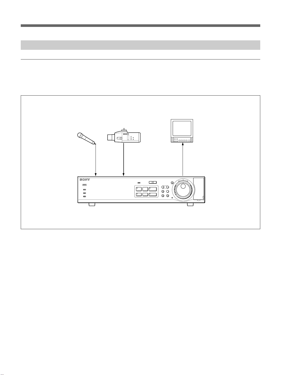
Basic single-camera system
You can record images captured by the connected
camera while observing the input on the video
monitor, and play back the recorded images.
Monitor
Microphone
POWER
ALARM
ALARM FULL
FULL
DIGITAL SURVEILLANCE RECORDER HSR-X200
Video camera
VIDEO
OUT
VIDEO
INMIC
HSR-X200/X200P
l
-
LOCK
PRE REVERSE PLAY
S PAUSE s STOP G PLAY
REC
TIMER
STOP
VIDEO
IN
VIDEO
OUT
MENU EXIT/OSD
ZOOM
FRAME/FIELD
CHANNEL COPY
SEARCH
SHUTTLE
HOLD
E
R
J
j
E
N
R
U
T
N
T
E
R
PUSH
ALARM
L
a REC
8 (GB)
Page 9
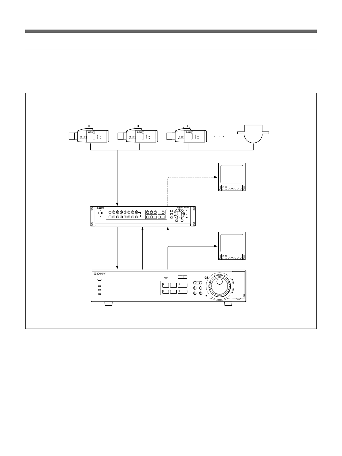
Multiple-camera system
You can record images captured by multiple cameras
connected to the multiplexer, and play back the
recorded images.
Video cameras
Monitor
b)
Multiplexer
POWER
ALARM
ALARM FULL
FULL
VIDEO
IN (COMPOSITE)
VIDEO
OUT
VIDEO
IN
DIGITAL SURVEILLANCE RECORDER HSR-X200
SW
OUT
MONITOR
OUT
SW VIDEO
IN
VIDEO
OUT
l
-
LOCK
PRE REVERSE PLAY
S PAUSE s STOP G PLAY
REC
TIMER
STOP
HSR-X200/X200P
a)
Monitor
MENU EXIT/OSD
ZOOM
FRAME/FIELD
CHANNEL COPY
SEARCH
SHUTTLE
HOLD
E
R
J
j
E
N
R
U
T
N
T
E
R
PUSH
ALARM
L
a REC
..........................................................................................................................................................................................................
a) Monitor for simultaneous recording/playback (with a
specific multiplexer manufactured by Sony, Sanyo,
Dedicated Micro, or Robot): Playback during recording
is possible. You can view the playback picture of a single
channel you specified full-screen without disturbing the
b)Monitor for playback only (with other most multiplexers):
During recording, you can only view the live image(s)
from the camera(s) full-screen or tiled.
Playback image(s) can be viewed either full-screen or
tiled.
recording in progress.
9 (GB)
Page 10
Overview
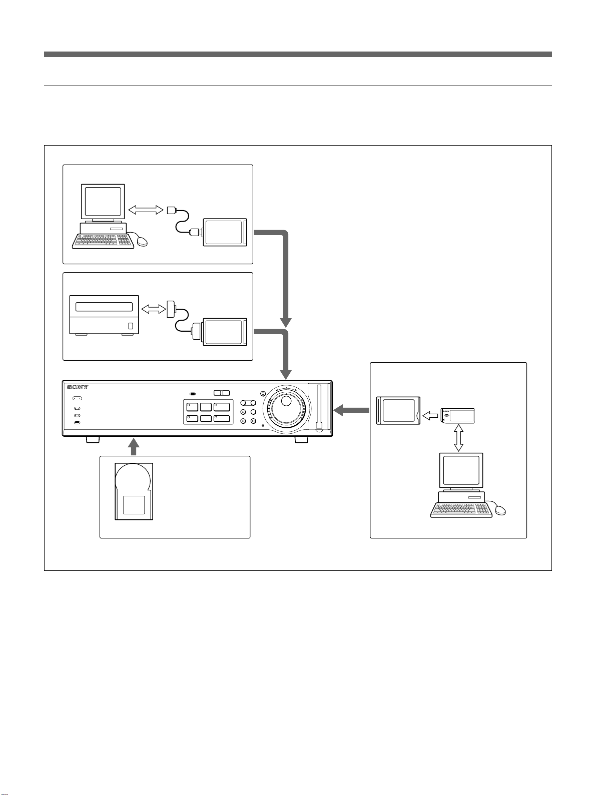
Support system
Besides the camera system, you can add various
peripheral devices to support the HSR-X200/X200P.
Network connection
Computer
Backup system
DDS drive
HSR-X200/X200P
POWER
ALARM
ALARM FULL
FULL
DIGITAL SURVEILLANCE RECORDER HSR-X200
ETHERNET
SCSI
LAN PC card
SCSI PC card
l
ALARM
REC
STOP
L
PRE REVERSE PLAY
a REC
-
LOCK
S PAUSE s STOP G PLAY
TIMER
Hard disk expansion
MENU EXIT/OSD
ZOOM
FRAME/FIELD
CHANNEL COPY
SEARCH
SHUTTLE
PC CARD
HOLD
E
R
J
j
E
N
R
U
T
N
T
E
R
Data download system
PC card adaptor
Memory stick
10 (GB)
HSBK-X201 hard disk drive
Computer
Page 11
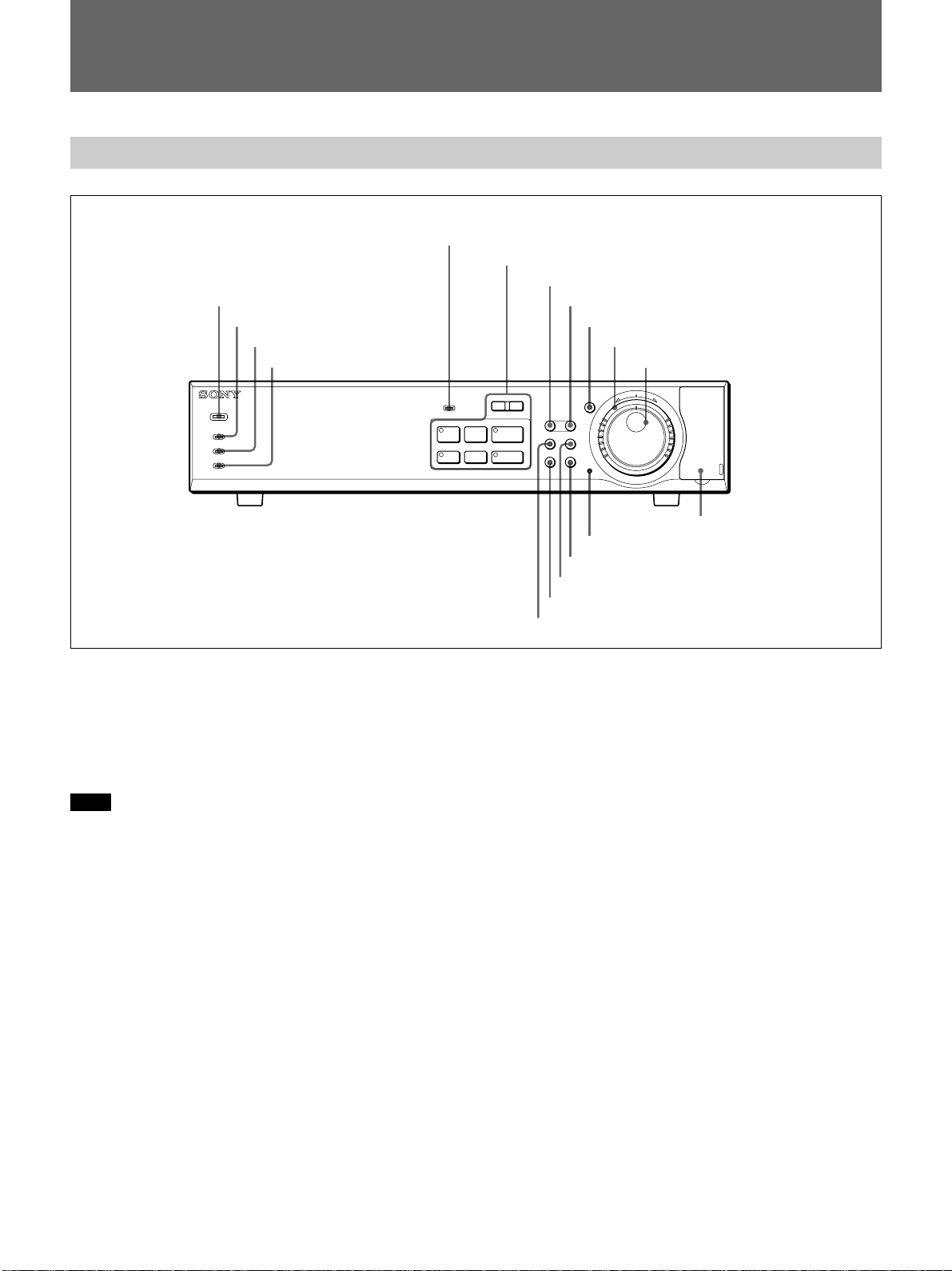
Locations and Functions of Parts
Front Panel
5 LOCK indicator
6 Record/Playback buttons
7 MENU button
1 POWER indicator
2 ALARM indicator
3 ALARM FULL indicator
4 FULL indicator
8 EXIT/OSD button
9 SHUTTLE HOLD button and indicator
0 Shuttle dial
qa Jog dial
POWER
ALARM
ALARM FULL
FULL
DIGITAL SURVEILLANCE RECORDER HSR-X200
LOCK
S PAUSE s STOP G PLAY
1 POWER indicator
Lights in green when the power is applied to the unit
and goes dark when the power is disconnected.
It flashes in red if any problem occurs with the harddisk drive or fan.
Note
In order to keep the unit internal temperature low, a
fan is provided on the side of the unit. If the fan does
not operate properly, the POWER indicator will flash
to indicate a problem. Unplug the unit from the power
supply and check to make sure nothing is obstructing
the fan. If after the power is restored to the unit, the
POWER indicator still flashes, do not use the unit and
consult your dealer.
2 ALARM indicator
Lights in red during pre-alarm recording and flashes in
red during alarm recording. It goes dark when
recording ends.
For alarm recording and pre-alarm recording, see “Alarm
Recording” on page 24(GB).
MENU EXIT/OSD
SEARCH
ZOOM
FRAME/FIELD
CHANNEL COPY
SHUTTLE
HOLD
j
N
R
U
T
E
R
J
E
N
T
E
R
PUSH
-
TIMER
REC
STOP
l
ALARM
PRE REVERSE PLAY
a REC
L
qj PC CARD slot
qh Menu reset button
qg COPY button and indicator
qf SEARCH FRAME/FIELD button
qd CHANNEL button and indicator
qs ZOOM button and indicator
3 ALARM FULL indicator
Flashes in red if the remaining capacity of the alarm
recording area of the built-in hard disk drops below the
specified value (default: 1%).
4 FULL indicator
Flashes in red if the remaining capacity of the normal
recording area of the built-in hard disk drops below the
specified value (default: 1%).
5 LOCK indicator
Lights in red when the security lock function is active.
When you press an operation button with this indicator
lit, the indicator flashes, and a message is displayed to
prompt you to enter a password.
For details on the security lock and password, see “Security
Lock Settings” on page 49(GB).
11 (GB)
Page 12
Locations and Functions of Parts
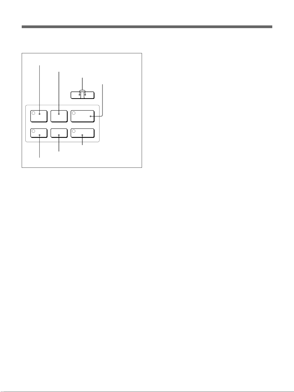
6 Record/Playback buttons
A X PAUSE button and indicator
B x STOP button
C . ALARM > skip buttons
D B PLAY/PRE
ALARM
l
PRE REVERSE PLAY
S PAUSE s STOP G PLAY
TIMER
E TIMER button and indicator
REC
STOP
F REC STOP button
a REC
G z REC button and indicator
L
REVERSE PLAY
button and
indicator
A X PAUSE button and indicator (amber)
When you press this button during playback, the unit
enters Still-Picture mode, and the indicator lights.
Press the button again to restore normal Playback
mode.
B x STOP button
Press this button to end playback (including that of
Still-Picture or Variable-Speed Playback mode).
C . ALARM > skip buttons
During playback of an alarm recording event, pressing
. skips to the previous alarm recording event, and
pressing > skips to the next alarm recording event.
During playback of an event in the archive area,
pressing . skips to the previous event, and pressing
> skips to the next event.
D B PLAY/PRE REVERSE PLAY button and
indicator (green)
When you press this button in stop status, the indicator
lights, and playback begins.
For details, see “Normal Playback” on page 31(GB).
By pressing the button during recording, you can view
the recorded images from the point before the
specified pre-reverse time (1 to 99 minutes) without
stopping the recording in progress (Pre-Reverse
Playback).
For details on the operation, see “Pre-Reverse Playback”
on page 31(GB).
12 (GB)
E TIMER button and indicator (red)
When you press this button, the unit enters timerstandby status, and the indicator lights. Recording will
begin at the starting time you specified using the
menu, and the REC button indicator will light.
Pressing the button again cancels timer-standby status
or timer recording in progress.
For details on the operation, see “Timer Recording” on
page 27(GB).
F REC STOP button
Press this button to end recording.
G z REC button and indicator (red)
When you press this button, the indicator lights, and
recording begins.
7 MENU button
When you press this button, the unit enters Menu
mode.
In Menu mode, you can switch between MAIN MENU 1
and MAIN MENU 2 or the menu items in sequence.
For details on the operation, see “Menu Operations” on
page 17(GB).
8 EXIT/OSD button
Press to quit Menu mode.
In modes other than Menu mode, this button functions
as the on-screen data switch.
Each time you press the button, the position of the onscreen data will change in sequence of lower left,
upper right, lower right, no display, and upper left.
For details on the on-screen data, see “On-screen Data” on
page 16(GB).
9 SHUTTLE HOLD button and indicator (green)
By pressing this button to light the indicator, you can
lock the direction and speed of playback dictated by
the current orientation of the Shuttle dial.
When you press the button again, the mode before you
start the variable-speed playback will be restored.
For details on the operation, see “Variable-Speed
Playback” on page 32(GB).
0 Shuttle dial (outer)
When you rotate the Shuttle dial in Playback mode
(PLAY button indicator lit) or in Still-Picture mode
(PAUSE button indicator lit), playback is performed
according to the direction and degree of the rotation.
For details on the operation, see “Variable-Speed
Playback” on page 32(GB).
In OSD operations, your selection or setting will be
accepted when you turn the dial clockwise.
Page 13

qa Jog dial (inner)
By rotating the Jog dial in Playback mode (PLAY
button indicator lit), you can gradually change the
playback speed. Clockwise rotation increases the
speed and counterclockwise rotation decreases it.
When you rotate the Jog dial in Still-Picture mode
(PAUSE button indicator lit), playback is performed
frame by frame. Clockwise rotation forwards the
frames and counterclockwise rotation reverses them.
For details on the operation, see “Variable-Speed
Playback” on page 32(GB).
In OSD operations, you can move the cursor on the
screen and select setting values using this dial.
qs ZOOM button and indicator (green)
The button permits you to zoom in on a part of the
camera input or playback image on the monitor screen.
Specify the part to be zoomed in using the Jog and
Shuttle dials.
While the zoom function is active, the indicator of the
ZOOM button lights. When you press the button
again, the normal size is restored.
For details on the operation, see “Zooming in on an Image”
on page 33(GB).
qh Menu reset button
Press this button to return the settings of the menu
items being displayed on the monitor to the factory-set
default settings.
qjPC CARD slot
By inserting a commercially available PC card
adaptor, copying of the recorded data to external
memory, such as memory sticks, will be enabled.
qd CHANNEL button and indicator (green)
When a multiplexer whose channel information can be
decoded is in use, channel selection will be enabled by
pressing this button. When you press this button in
Playback mode, the channel selection display appears
to specify the channel to be output. In this mode, the
indicator of the CHANNEL button lights.
Pressing the button again to turn off the indicator
resumes All-Channel mode.
For details, see “Multiplexer Connection and Associated
Settings” on page 39(GB).
qfSEARCH FRAME/FIELD button
When you press this button in a recording mode or in
stop status, the search operation display appears.
When an image recorded in Frame Recording mode is
played in Still-Picture mode, you can switch between
frame display and field display by pressing this button.
For details, see “Playback” on page 31(GB).
qg COPY button and indicator (green)
Press this button to copy the data to the archive area of
the built-in hard disk, a memory stick, or a DDS tape.
The indicator lights, and the copy-operation display
appears.
For details on the operation, see “Data Storage” on page
29(GB).
13 (GB)
Page 14
Locations and Functions of Parts
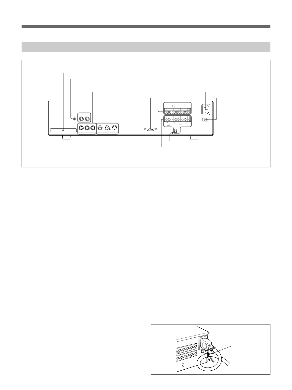
Rear Panel
1 PC CARD slot
2 MIC connector
3 AUDIO connectors
4 S-VIDEO connectors
5 VIDEO connectors 6 RS-232C connector
AUDIO
MIC
ININOUT
PC CARD
OUTLOOP OUT IN OUTLOOP OUT
S-VIDEO VIDEO
RS-232C
0 Control terminals
9 Alarm terminals
WARNING OUT
NON REC OUT
CLOCK
ALARM
RESET
IN INOUT OUT
AB
REMOTE
RS485
RS485
TERMINATE
qa All Reset button
ALARM
COMCOM
FULL
FULL
-AC IN
IN OUTCOM COMCOMCOM COM
SW OUT
SERIES
ON
OFF
7 -AC IN connector
8 Power cord holder
1 PC CARD slot
For PC cards of Type 2.
Insert a commercially available SCSI PC card to
enable data backup using a DDS tape drive. If you
insert a commercially available LAN PC card, network
control will be enabled.
2 MIC (microphone) connector (monaural
minijack)
Connect a microphone for audio recording.
3 AUDIO connectors (phono jacks)
IN: Connect an audio signal.
OUT: Connect to the AUDIO IN connector of a
monitor.
4 S-VIDEO connectors (Mini DIN 4-pin)
IN: Connect a Y/C-separated S-VIDEO signal.
LOOP OUT: The signal supplied to the IN connector
is output as-is. The signal is output even when the
power to the HSR-X200/X200P is off.
OUT: A Y/C-separated S-VIDEO signal will be
supplied. Connect to the S-VIDEO input of a
playback monitor. When the S-VIDEO signal is to
be monitored via a multiplexer, connect to the
S-VIDEO input of the multiplexer.
5 VIDEO connectors (BNC type)
IN: Connect a video camera. When using a
multiplexer, connect the video output connector of
the multiplexer to this input.
LOOP OUT: The signal supplied to the IN connector
is output as-is. The signal is output even when the
power to the HSR-X200/X200P is off.
OUT: Connect to the VIDEO IN connector of a
playback monitor. A composite video signal will
be supplied. Character signals are superimposed
on the output video signal. When the video signal
is to be monitored via a multiplexer, connect to the
video input connector of the multiplexer.
6 RS-232C connector (D-sub 9-pin)
An external controller, such as a PC, can be connected.
7 -AC IN connector
Connect AC power using the supplied AC power cord.
8 Power cord holder
Secure the AC power cord using the supplied tie, as
shown below.
Tie
14 (GB)
Page 15
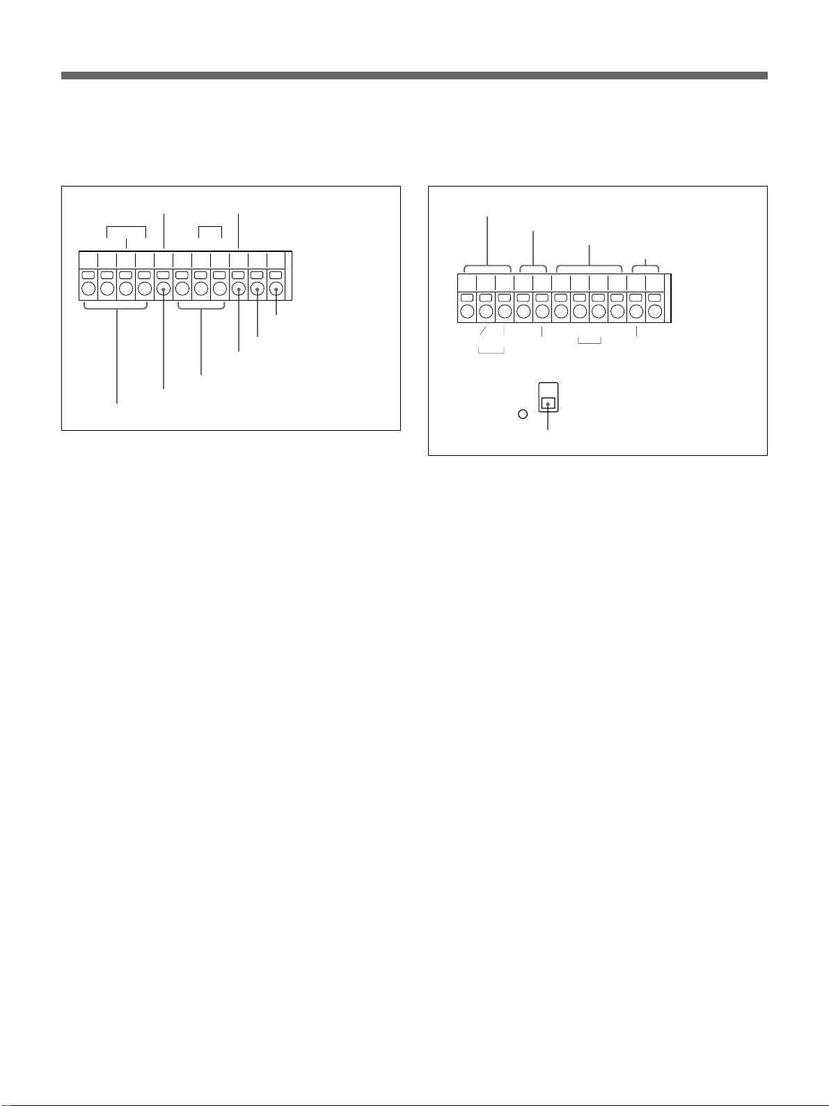
9 Alarm terminals
For input and output of various alarm and timing
signals. The COM terminals are all for ground.
0 Control terminals
For input and output of various control signals. The
COM terminals are for ground.
NON REC OUT
ALARM
RESET
IN INOUT OUT
ALARM terminals
NON REC OUT terminal
WARNING OUT
CLOCK
COMCOM
CLOCK terminals
ALARM
FULL
FULL
ALARM FULL terminal
FULL terminal
WARNING OUT terminal
ALARM terminals
For signals that can be triggered for alarm recording
IN: Alarm signal input (normally-open contact)
RESET: Alarm reset input (normally-open contact)
OUT: Sensor alarm signal output (5V DC/5.7 kΩ).
The output level drops to 0 V when the built-in
activity detection sensor operates or an external
alarm is detected.
NON REC OUT terminal (5V DC/5.7 kΩ)
The output level drops to 0 V if recording is
interrupted.
RS485 terminals
AB
RS485
REMOTE terminal
REMOTE
RS485
TERMINATE
RS485 TERMINATE switch
SERIES terminals
IN OUTCOM COMCOMCOM COM
SERIES
ON
OFF
SW OUT terminal
SW OUT
RS485 terminals
For an RS-485 interface. Connect to the A, B, and
COM (ground) pins of a controller using a twisted-pair
cable.
For the connections, see “Remote Control Connections and
Associated Settings” on page 41(GB).
REMOTE terminals (resistor-alley system)
For remote control.
For the connections, see “Remote Control Connections and
Associated Settings” on page 41(GB).
CLOCK terminals
You may adjust the built-in clock using an external
switch or synchronize the clocks of other connected
devices to the clock of this unit.
IN: Clock input (normally-open contact). Connect an
external switch or equivalent.
OUT: Clock output (5V DC/5.7 kΩ). The output level
drops to 0 V at the time you specified by menu
operation.
WARNING OUT terminal (5V DC/5.7 kΩ)
The output level drops to 0 V if any problem occurs
with the HDD or fan.
FULL terminal (5V DC/5.7 kΩ)
The output level drops to 0 V if the remaining capacity
of the normal recording area of the built-in hard disk
drops below the specified value (default: 1%).
ALARM FULL terminal (5V DC/5.7 kΩ)
The output level drops to 0 V if the remaining capacity
of the alarm recording area of the built-in hard disk
drops below the specified value (default: 1%).
SERIES terminals
To connect the control signal in series when
connecting video and audio signals for multiple HSRX200/X200P units in series.
IN: Connect to the OUT terminal of the previous
HSR-X200/X200P unit.
OUT: Connect to the IN terminal of the next HSR-
X200/X200P unit.
SW OUT terminals (5V DC/5.7 kΩ)
For pulse signal output. By connecting to SW of a
multiplexer, you may control the timing to switch the
input picture.
RS485 TERMINATE switch
For RS-485 termination. When connecting multiple
HSR-X200/X200P units in series via the RS485
terminals, set this switch of the last HSR-X200/X200P
unit to ON.
qa All Reset button
For CPU reset
15 (GB)
Page 16
Locations and Functions of Parts
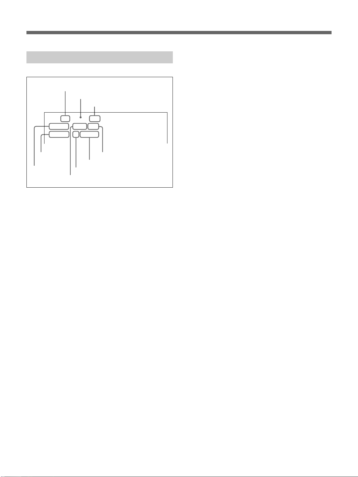
On-Screen Data
7 Channel (camera) number
8 Operation status
9 Remaining of recording area
4CH z 100%
01-01-01 ALARM 0000
00:00:00 HI 0.10SEC
2 Time
1 Date
4 Picture quality
3 Alarm type
By pressing the EXIT/OSD button on the front panel,
you can change the display position or even make
them disappear.
Items 1 to 6 can be independently turned on/off with
DISPLAY/VIDEO LOSS SET of MAIN MENU 2.
6 Alarm count
5 Recording cycle
7 Channel (camera) number
When a multiplexer whose channel information can be
decoded is connected, the camera number you selected
is displayed.
8 Operation status
The current operation mode is displayed.
z: Recording
B: Playback
X: Still
M: Variable speed playback in the forward direction
m: Variable speed playback in the reverse direction
9 Remaining of recording area
When the recording area OVERWRITE function is set
to OFF with the RECORDING CONDITIONS SET
(page 47(GB)), the remaining capacity of the
menu
recording area is displayed (in %).
1 Date/2 Time
In a recording mode or stop status (monitoring the
camera input), the current date (month-day-year on the
HSR-X200/day-month-year on the HSR-X200P) and
time (hour:min:sec) are displayed.
In playback, the date and time when the recording has
made are displayed.
3 Alarm type
The active alarm type is displayed.
ALARM: Alarm recording
PRE-ALARM: Pre-alarm recording
4 Picture quality/5 Recording cycle
In a recording mode or stop status, the picture quality
and recording cycle specified for normal recording are
displayed.
In playback, the picture quality and recording cycle
when the recording has made are displayed.
6 Alarm count
Each time alarm recording is made, the value is
increased by one.
The value will return to 1 if it exceeds 9999.
16 (GB)
Page 17
Basic OSD Operations
You can perform various settings on the monitor
screen.
For the on-screen displays, you can select from among
English, French, Spanish and German (HSR-X200P only)
with a menu operation. See page 44(GB).
For the menu layers, see page 19(GB).
The display examples in this manual are those for the
HSR-X200P.
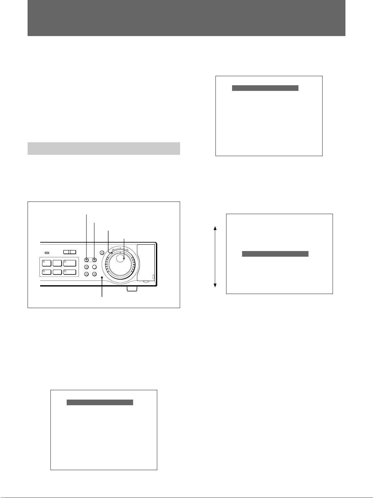
Menu Operations
This section describes how to set a menu item as an
example of OSD (On-Screen Display) operations.
Buttons and dials used in menu operations
MENU button
EXIT/OSD button
Shuttle dial
Jog dial
l
REC
STOP
ALARM
PRE REVERSE PLAY
a REC
-
LOCK
S PAUSE s STOP G PLAY
TIMER
L
SHUTTLE
HOLD
MENU EXIT/OSD
SEARCH
ZOOM
FRAME/FIELD
CHANNEL COPY
Menu reset button
j
N
R
U
T
E
R
J
E
N
T
E
R
PUSH
To switch to MAIN MENU 2
Press the MENU button again.
<MAIN MENU 2>
1. DISPLAY/VIDEO LOSS SET c
2. RS-232C/RS-485 SET c
3. BUZZER SET c
4. SECURITY LOCK SET c
5. NETWORK SET c
6. HDD SET c
7. POWER FAILURE/USED TIME c
TO MAIN MENU 1 c
MOVE LINES WITH JOG, SELECT WITH SHUTTLE
To move the highlighting
Turn the Jog dial. Clockwise rotation moves the menu
bar downward and counterclockwise rotation moves it
upward.
Counterclockwise
Clockwise
<MAIN MENU 1>
1. LANGUAGE/CLOCK SET c
2. VIDEO INPUT/PRE REVERSE c
3. RECORDING AREA SET c
4. RECORDING CONDITIONS SET c
5. NORMAL REC MODE SET c
6. TIMER SET c
7. HOLIDAY SET c
8. ALARM REC MODE SET c
TO MAIN MENU 2 c
MOVE LINES WITH JOG, SELECT WITH SHUTTLE
The SEARCH and COPY buttons also associate their
own menus.
For these menus, see page 34(GB) or see page 30(GB).
To start a menu operation
Press the MENU button. MAIN MENU 1 appears on
the monitor screen.
The menu bar highlights the top item.
<MAIN MENU 1>
1. LANGUAGE/CLOCK SET c
2. VIDEO INPUT/PRE REVERSE c
3. RECORDING AREA SET c
4. RECORDING CONDITIONS SET c
5. NORMAL REC MODE SET c
6. TIMER SET c
7. HOLIDAY SET c
8. ALARM REC MODE SET c
TO MAIN MENU 2 c
MOVE LINES WITH JOG, SELECT WITH SHUTTLE
To select a menu item
Move the menu bar to highlight the desired item using
the Jog dial, then turn the Shuttle dial clockwise to
finalize your selection.
The setting display for the selected menu item appears.
To page the setting displays
When the setting display of menu item is displayed on
the monitor, you can jump to that of the next menu
item in sequence by pressing the MENU button.
For example, you can jump from “1. LANGUAGE/
CLOCK SET” to “2. VIDEO INPUT/PRE REVERSE”
by pressing the MENU button.
To return to MAIN MENU 1 or 2 from the
setting display of a menu item
Turn the Shuttle dial counterclockwise.
17 (GB)
Page 18
Basic OSD Operations
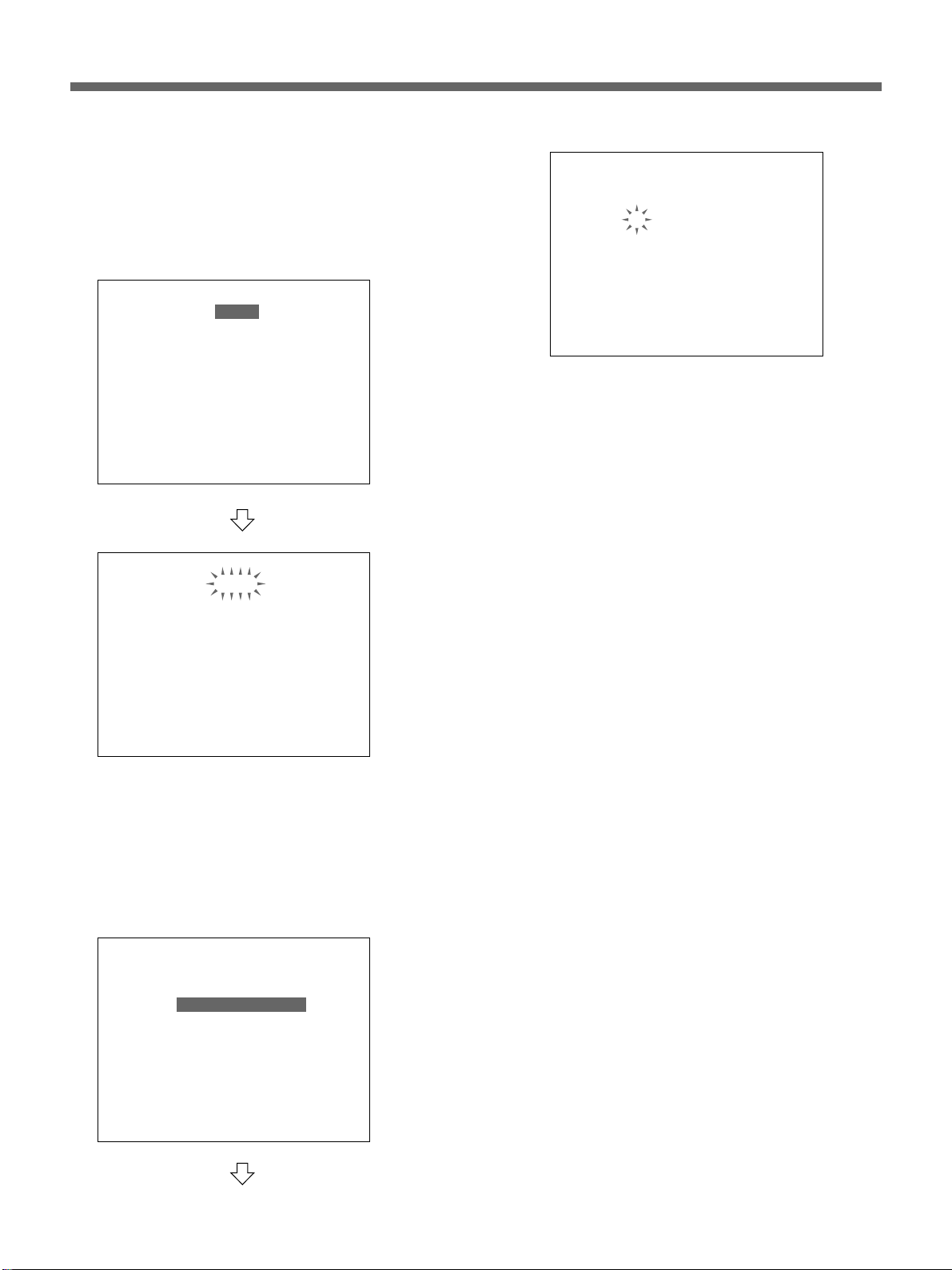
To set an item
1 When setting the highlighted item, simply turn the
Shuttle dial clockwise.
The current setting begins to flash.
<LANGUAGE/LANGUE/SPRACHE/IDIOMA>
ENGLISH
<CLOCK SET>
22-01-2001 MON 09:01:00
<SUMMER TIME SET>
MODE : NO USE
WEEK MONTH TIME
ON LST-SUN O3 02:00
0FF LST-SUN 10 02:00
<EXT. CLOCK SET>
ADJUST. TIME : 01:00
<LANGUAGE/LANGUE/SPRACHE/IDIOMA>
ENGLISH
<CLOCK SET>
22-01-2001 MON 09:01:00
<SUMMER TIME SET>
MODE : NO USE
WEEK MONTH TIME
ON LST-SUN O3 02:00
0FF LST-SUN 10 02:00
<EXT. CLOCK SET>
ADJUST. TIME : 01:00
<LANGUAGE/LANGUE/SPRACHE/IDIOMA>
ENGLISH
<CLOCK SET>
22-01-2001 MON 09:01:00
<SUMMER TIME SET>
MODE : NO USE
WEEK MONTH TIME
ON LST-SUN O3 02:00
0FF LST-SUN 10 02:00
<EXT. CLOCK SET>
ADJUST. TIME : 01:00
2 To change the setting at the flashing line or
column, turn the Jog dial.
The values (settings) you can select for the flashing
line or column are displayed in sequence.
3 When the desired value (setting) is displayed, turn
the Shuttle dial clockwise to register the new value
(setting).
The next column, if any on the same line, starts
flashing. Set it in the same manner.
By turning the Shuttle dial counterclockwise, you can
reverse the setting procedure.
When the setting(s) on one line ends, the next line you
can set will be highlighted when you turn the Shuttle
dial clockwise.
Or, select the item to be set by moving the
highlighting with the Jog dial, and turn the Shuttle
dial clockwise to finalize your selection.
On the line where multiple inputs are required, the
first column begins to flash.
<LANGUAGE/LANGUE/SPRACHE/IDIOMA>
ENGLISH
<CLOCK SET>
22-01-2001 MON 09:01:00
<SUMMER TIME SET>
MODE : NO USE
WEEK MONTH TIME
ON LST-SUN O3 02:00
0FF LST-SUN 10 02:00
<EXT. CLOCK SET>
ADJUST. TIME : 01:00
18 (GB)
To return the settings to the defaults
Press the Menu Reset button on the front panel using a
thin pointed implement.
All the settings of the menu item being displayed on
the monitor screen will return to their factory-set
values.
To exit Menu mode
Press the EXIT/OSD button.
Page 19

Menu Layers
MAIN MENU 1
1. LANGUAGE/CLOCK SET
LANGUAGE
ENGLISH/FRANÇAIS/DEUTSCH
ESPAÑOL
CLOCK SET
2)
dd-mm
SUMMER TIME SET
MODE
USE/NO USE
ON WEEK/MONTH/TIME
OFF WEEK/MONTH/TIME
EXT. CLOCK SET
ADJUST. TIME
hh:mm
2. VIDEO INPUT/PRE REVERSE
VIDEO INPUT/MULTIPLEXER
SONY/OTHERS1/OTHERS2/NO USE
PRE REVERSE PLAY/
PRE REVERSE PLAY TIME
n
3. RECORDING AREA SET
TOTAL CAPACITY
NORMAL RECORDING AREA
AREA FULL RESET
ALARM RECORDING AREA
AREA FULL RESET
ARCHIVE AREA
AREA FULL RESET
4. RECORDING CONDITIONS SET
SERIES RECORDING
ON/OFF
NORMAL RECORDING AREA/OVERWRITE
ON/OFF
ALARM RECORDING AREA/OVERWRITE
ON/OFF
REMAINING DISK WARNING
n
%
1) HSR-X200P only
2)
mm-dd
3) DAYLIGHT SAVINGS with HSR-X200
with HSR-X200
-yyyy/hh:mm:ss
3)
MIN
5. NORMAL REC MODE SET
PICTURE QUALITY
HYPER/SUPER/HIGH/MID/LOW
FRAME/FIELD RECORDING
1)
/
FRAME/FIELD
AUDIO RECORDING
ON/OFF
REC CYCLE
n
SEC
6. TIMER SET
WEEK
SUN/MON/THU/WED/THU/FRI/SAT/
DLY
START
hh:mm
STOP
hh:mm
REC CYCLE
n
SEC
7. HOLIDAY SET
2)
dd-mm
8. ALARM REC MODE SET
PICTURE QUALITY
HYPER/SUPER/HIGH/MID/LOW
FRAME/FIELD RECORDING
FRAME/FIELD
AUDIO RECORDING
ON/OFF
ALARM RECORDING
MODE1/MODE2/MODE3/MODE4
REC CYCLE
n
SEC
DURATION
1S/2S/5S/10S/20S/40S/1M/2M/
3M/4M/5M/10M/15M/CC
PRE-ALARM RECORDING
ON/OFF
REC CYCLE
n
SEC
DURATION
1S/2S/5S/10S/20S/40S/1M/2M/
3M/4M/5M/10M/15M
ALARM TRIGGER
ALARM/SENSOR/ALARM OR SENSOR/
ALARM AND SENSOR
ACTIVITY SENSOR
TO MAIN MENU 2
19 (GB)
Page 20

Basic OSD Operations
MAIN MENU 2
1. DISPLAY/VIDEO LOSS SET
DISPLAY SET
DATE
TIME
QUALITY
REC CYCLE
ALARM COUNT
ALARM TYPE
VIDEO LOSS SET
VIDEO LOSS
2. RS-232C/RS-485 SET
CONTROL
RS-232C/RS-485
DATA SPEED
2400/4800/9600/19200
STATUS INFO
ON/OFF
ALARM INFO
ON/OFF
ADDRESS
ON/OFF
ON/OFF
ON/OFF
ON/OFF
ON/OFF
ON/OFF
ON/OFF
5. NETWORK SET
LAN CARD
LAN1/LAN2
NETWORK CONTROL
ON/OFF
IP ADDRESS
SUBNET MASK
GATEWAY
PASSWORD SET/ID/PASSWORD
ID1
ID2
ID3
6. HDD SET
DISK 1
DISK 2
DISK INITIALIZE
MIRRORING
ON/OFF
PLAYBACK DRIVE
DISK1/DISK2
7. POWER FAILURE/USED TIME
POWER FAILURE
USED TIME
FIRMWARE
TO MAIN MENU 1
3. BUZZER SET
4. SECURITY SET
20 (GB)
ALARM
ON/OFF
DISK FULL
ON/OFF
DISK ERROR
ON/OFF
LOCK WARNING
ON/OFF
KEY IN
ON/OFF
NON REC
ON/OFF
ADMIN
PASSWORD
ON/OFF
USER
PASSWORD
ON/OFF
REC CONTROL
ADMIN/USER
SEARCH
ALARM SEARCH
ALARM THUMBNAIL SEARCH
TIME/DATE SEARCH
ARCHIVE AREA SEARCH
ACTIVITY DETECTION SEARCH
ARCHIVE SET
BACKUP
RESTORE
ERASE
Page 21

Overview of Recording
Types of Recording
The HSR-X200/X200P records video and audio (1
channel) in normal recording, alarm recording, or
timer recording.
Normal recording
Initiated by pressing the z REC button, video and
audio are recorded in the normal recording area of the
built-in hard disk.
Alarm recording
Initiated by a trigger, such as an external signal or the
internal sensor, video and audio are recorded in the
alarm recording area of the built-in hard disk.
It is also possible to record tracing the specified time
back from a trigger (Pre-alarm recording).
Timer recording
Recording is made during the specified period(s).
Video and audio are recorded in the normal recording
area of the built-in hard disk.
Data recorded by normal recording, alarm recording,
or timer recording can be stored in the archive area
assigned independently from the normal and alarm
recording areas with a copy operation.
For details on operations, see “Data Storage” on page
29(GB).
Series recording
By connecting two or more HSR-X200/X200P units in
series, recording can be continued on the subsequent
units after a recording area of one HSR-X200/X200P
becomes full.
When such series recording is activated with
RECORDING CONDITIONS SET of MAIN
MENU 1, recording will start on the second HSRX200/X200P when the recording area of the first HSRX200/X200P becomes full.
For details on connections and settings for series recording,
see “Series Connections and Associated Settings” on page
38(GB).
Zoom in on the Camera Input
When the unit is in stop status or in a recording mode,
you can zoom to a part of the picture from the camera
on the monitor screen.
The operation is the same as with a playback picture.
Zooming on the monitor has no effect on recording.
See “Zooming in on an Image” on page 33(GB).
Areas for Recording
The built-in hard disk (80 GB) is partitioned into the
normal recording area, alarm recording area, and
archive area for data storage.
The default is 80% assigned to the normal recording
area and 19% assigned to the alarm recording area
with the remaining 1% assigned to the archive area.
You may change these percentages using
RECORDING AREA SET of MAIN MENU 1.
For the normal recording area and alarm recording
area, RECORDING CONDITIONS SET of MAIN
MENU 1 permits you to choose whether to stop
recording or overwrite when each area becomes full.
The data in each area can be erased with a reset
operation.
For details, see “Recording Area Settings” on page 46(GB).
21 (GB)
Page 22

Normal Recording
Settings for Normal Recording
For normal recording, you may select an appropriate
picture quality, frame or field recording, audio
recording, and a recording cycle. Use NORMAL REC
MODE SET of MAIN MENU 1.
<NORMAL REC MODE SET>
PICTURE QUALITY : HIGH
FRAME/FIELD RECORDING : FIELD
AUDIO RECORDING : ON
REC CYCLE : A 0.10 SEC ( 20H)
PICTURE QUALITY
Select an appropriate picture quality from among 5
levels. The default is HIGH.
HYPER: To record with 58 KB/field (including a
header of 2 KB)
SUPER: To record with 44 KB/field (including a
header of 2 KB)
HIGH: To record with 32 KB/field (including a
header of 2 KB)
MID: To record with 24 KB/field (including a header
of 2 KB)
LOW: To record with 17 KB/field (including a header
of 2 KB)
The lower the mode you select, the longer the possible
recording time becomes.
FRAME/FIELD RECORDING
Select the image capture mode.
FRAME: To record an image in units of frames. This
allows you to select frame display or field display
when playing back the image.
FIELD: To record an image in units of fields.
REC CYCLE
You may select from among 27 steps (displayed by
rounding off to the second decimal place).
The recording cycles in frame mode are doubled
compared with those in field mode.
For the table of recording cycles and recording times, see
page 61(GB).
Setting procedure
1 Press the MENU button to display MAIN MENU 1
on the monitor screen.
2 Turn the Jog dial to highlight 5. NORMAL REC
MODE SET and turn the Shuttle dial clockwise.
The NORMAL REC MODE SET display appears.
3 Turn the Jog dial to highlight the item to be set and
turn the Shuttle dial clockwise to finalize your
selection.
The current setting of the selected line flashes.
4 Turn the Jog dial to change to the desired setting
and turn the Shuttle dial clockwise to register the
new setting.
According to the selected picture quality and
recording cycle, the possible recording time is
automatically calculated and displayed (in units of
hours) in parentheses at the right end of the REC
CYCLE line.
When you set AUDIO RECORDING to ON, “A”
is displayed before the REC CYCLE value if audio
recording is valid with the specified recording
cycle.
5 Press the EXIT/OSD button to exit the menu.
AUDIO RECORDING
To record an audio channel along with images, set
AUDIO RECORDING to ON.
Note
Audio recording can be activated when you select a
REC CYCLE value less than 0.10 (HSR-X200)/0.12
(HSR-X200P) in FIELD mode or 0.20 (HSR-X200)/
0.24 (HSR-X200P) in FRAME mode.
22 (GB)
Page 23
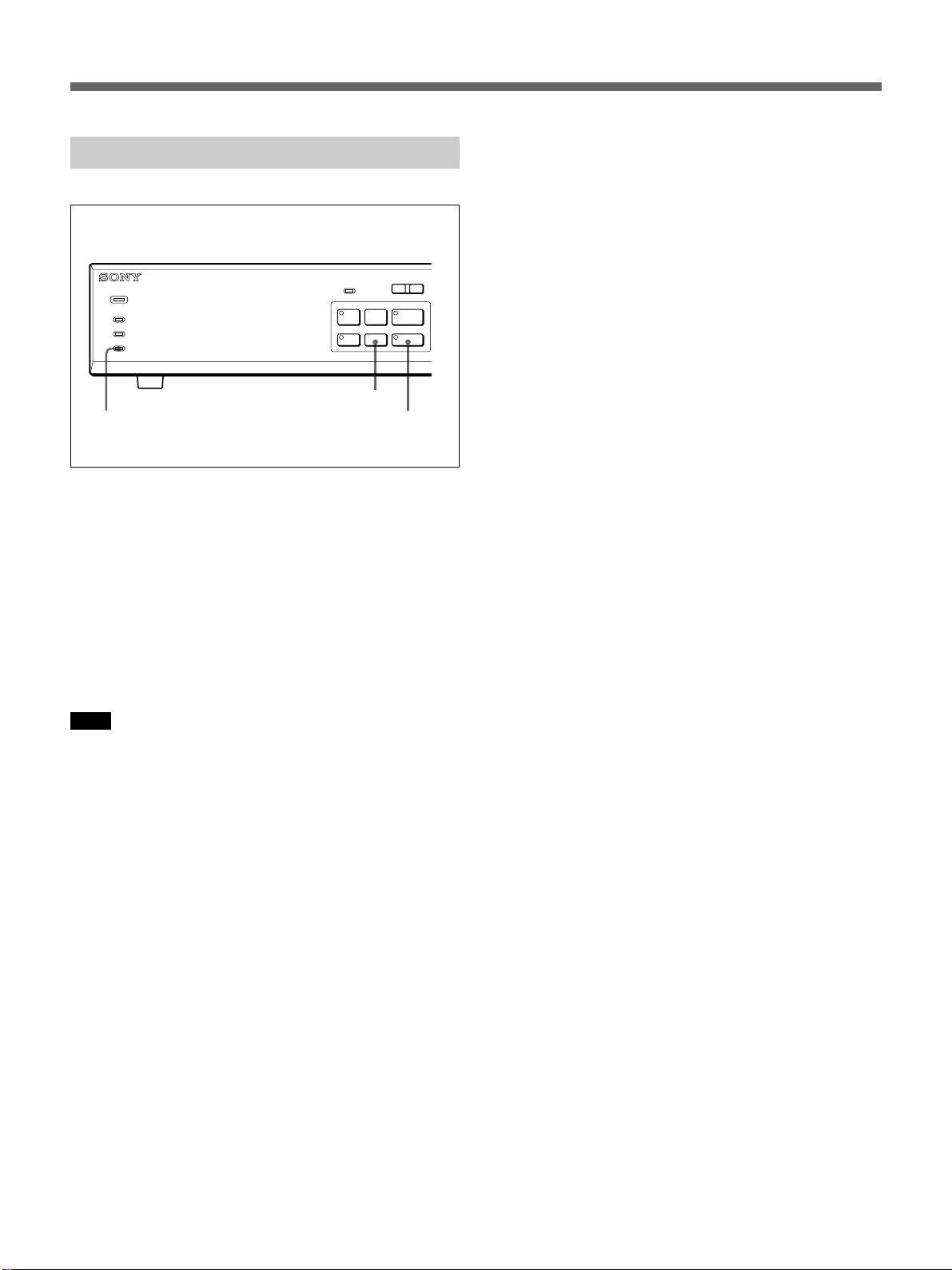
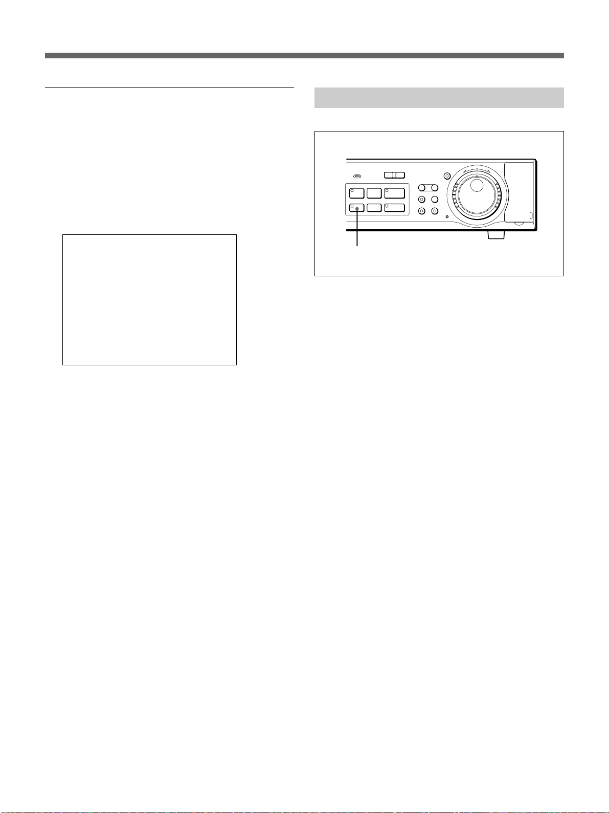
Procedure of Normal Recording
ALARM
L
l
-
POWER
ALARM
ALARM FULL
FULL
DIGITAL SURVEILLANCE RECORDER HSR-X200
REC STOP button
FULL indicator
To start recording
Press the z REC button.
The indicator on the z REC button lights, and
recording begins.
Recording is made with the specified picture quality
and at the specified recording cycle in the normal
recording area.
When you set AUDIO RECORDING to ON and audio
recording is valid with the specified recording cycle,
audio is recorded with video.
LOCK
PRE REVERSE PLAY
S PAUSE s STOP G PLAY
REC
TIMER
a REC
STOP
z REC button
and indicator
Note
When timer recording has been set (the indicator on
the TIMER button lit), recording cannot be started
with the z REC button. First press the TIMER button
to cancel timer recording.
When the normal recording area becomes full
If overwriting of the normal recording area has been
set to OFF, a warning message will appear on the
monitor screen when the remaining capacity drops to
the specified value (1% with the default). At the same
time, the FULL indicator flashes and a warning signal
is output from the FULL terminal on the rear panel.
The overwriting ON/OFF setting and the value of the
remaining for warning can be changed with
RECORDING CONDITIONS SET of MAIN
MENU 1.
For details, see page 46(GB).
To stop recording
Press the REC STOP button.
23 (GB)
Page 24

Alarm Recording
The HSR-X200/X200P automatically starts alarm
recording when it detects the specified trigger.
For the trigger, you can select the following alarm
signals independently or in combination:
1. External alarm input
2. Internal alarm generated by the built-in activity
detection sensor when it detects a change in
luminance at the specified points on the camera
input picture.
By activating pre-alarm recording, the HSR-X200/
X200P continues recording the camera input,
overwriting the data for the specified duration. When
the trigger is detected, the HSR-X200/X200P switches
to regular alarm recording. This enables you to check
the image a certain time before the trigger is actually
detected.
Note
When a multiplexer is in use, you can only select
external alarm input for the trigger and must select a
certain channel (camera number) to be recorded.
For channel selection, see “Multiplexer Channel Selection”
on page 33(GB).
Settings for Alarm Recording
For alarm recording, you may set the following
requirements, including the trigger.
Use ALARM REC MODE SET of MAIN MENU 1.
<ALARM REC MODE SET>
PICTURE QUALITY : SUPER
FRAME/FIELD RECORDING : FIELD
AUDIO RECORDING : ON
ALARM RECORDING : MODE1
REC CYCLE : 0.33 SEC, DURATION : 40 SEC
PRE-ALARM RECORDING : ON
REC CYCLE : A 0.05 SEC, DURATION : 1 MIN
c (1010 ALARMS CAN BE RECORDED)
ALARM TRIGGER : ALARM AND SENSOR
ACTIVITY SENSOR c
ALARM RECORDING
Select the mode to execute alarm recording.
MODE1: To execute alarm recording regardless of
timer recording
MODE2: To execute alarm recording only while timer
recording is in progress
MODE3: To execute alarm recording only while timer
recording is not in progress
MODE4: To execute alarm recording during the
period(s) set for timer recording (timer recording
itself is not performed)
Set to OFF when no alarm recording is required.
DURATION
Set the duration for alarm recording.
You may select from among 1S/2S/5S/10S/20S/40S/
1M/2M/3M/4M/5M/10M/15M/CC.
With CC, recording is made as long as the alarm signal
is ON.
PRE-ALARM RECORDING
To perform pre-alarm recording, set PRE-ALARM
RECORDING to ON, and select REC CYCLE and
DURATION of pre-alarm recording.
For the duration, you may select from among 1S/2S/
10S/20S/40S/1M/2M/3M/4M/5M/10M/15M.
Note
You cannot highlight PRE-ALARM RECORDING on
the display with ALARM RECORDING set to OFF.
ALARM TRIGGER
Select the trigger.
ALARM: External alarm input
SENSOR: Internal alarm generated by the built-in
activity detection sensor
ALARM AND SENSOR: Simultaneous occurrence
of external and internal alarms
ALARM OR SENSOR: Occurrence of either an
external or internal alarm
Setting procedure
PICTURE QUALITY
FRAME/FIELD RECORDING
AUDIO RECORDING ON/OFF
REC CYCLE
These items can be set the same as for normal
recording.
24 (GB)
1 Press the MENU button to display MAIN MENU 1
on the monitor screen.
2 Turn the Jog dial to highlight 8. ALARM REC
MODE SET and turn the Shuttle dial clockwise.
The ALARM REC MODE SET display appears.
Page 25

3 Turn the Jog dial to highlight the item to be set and
turn the Shuttle dial clockwise to finalize your
selection.
The current setting on the selected line flashes.
4 Turn the Jog dial to change to the desired setting
and turn the Shuttle dial clockwise to register the
new setting.
When you set REC CYCLE for ALARM
RECORDING, the number of alarm events that
can be recorded is automatically calculated
according to the PICTURE QUALITY setting and
the available alarm recording area size and
displayed in parentheses on the third line from the
bottom.
Note
As long as the normal recording area has been
established on the hard disk, the recording cycle
for pre-alarm recording is limited to 0.05 SEC
(HSR-X200) or 0.06 SEC (HSR-X200P) at
maximum. If you cancel the normal recording area
(by setting the area to 0%), the recording cycle for
pre-alarm recording can be set to 0.02 SEC at
maximum.
5 When you use the built-in activity detection sensor
as a trigger, set the sensing points and the
sensitivity (see below).
- - - - - - - - - -
- - - - - - - - - -
- - - - - - - - - -
- - - - - - - - - -
- - - - - - - - - -
- - - - - - - - - -
- - - - - - - - - -
- - - - - - - - - LEVEL : 1 EXIT
To turn on the sensor at a point
Turn the Jog dial so that the mark at the point where
you wish to activate the sensor flashes, and turn the
Shuttle dial clockwise so that the flashing mark
x
changes to
.
Set the marks at all the points where you wish to
x
activate the sensor to
in the same manner.
Example:
- - - - - - - - - -
- - - - - - - - - -
- - -
- - -
- - -
- - - - - - - - - -
- - - - - - - - - -
- - - - - - - - - LEVEL : 1 EXIT
x
x x - - - -
x
x x - - - -
x
x x - - - -
6 When the settings on the ALARM REC MODE
SET display are completed, press the EXIT/OSD
button to exit the menu
Setting the activity detection sensor
When you use the built-in activity detection sensor, it
is necessary to set the sensing points and the
sensitivity.
Highlight ACTIVITY SENSOR and turn the Shuttle
dial clockwise to enter Sensor Set mode.
The sensor marks are displayed on a 10 × 8 grid on the
monitor, and the top left mark flashes.
To set the sensitivity
You can select the sensitivity level in the range of 1 to
10. The smaller the value you select, the higher the
sensitivity becomes. Setting to 1 provides the highest
sensitivity.
1 Turn the Jog dial clockwise at the bottom right
sensor point to highlight LEVEL and turn the
Shuttle dial clockwise.
The current setting flashes.
The sensor is deactivated with LEVEL set to OFF.
2 Turn the Jog dial to display the desired value, and
turn the Shuttle dial clockwise to register the
setting.
To end sensor setting
Highlight EXIT and turn the Shuttle dial clockwise.
The previous display will be restored.
25 (GB)
Page 26

Alarm Recording
Alarm Recording Procedure
When the specified trigger is detected, recording
automatically begins.
Recording is executed with the conditions specified
with ALARM REC MODE SET on the alarm
recording area.
Each time alarm recording is made, the alarm count on
the monitor increases by one.
The value returns to 1 when it exceeds 9999.
When you set pre-alarm recording to ON, the HSRX200/X200P immediately starts pre-alarm recording
when you exit the menu, and continues recording the
camera input, overwriting the data in the alarm
recording area for the specified duration. When the
trigger is detected, it starts regular alarm recording.
During pre-alarm recording, the indicator of the
ALARM button lights.
It flashes during alarm recording.
When the alarm recording area becomes full
If overwriting of the alarm recording area has been set
to OFF, a warning message will appear on the monitor
screen when the remaining capacity drops to the
specified value (1% with the default). At the same
time, the ALARM FULL indicator flashes, and a
warning signal is output from the ALARM FULL
terminal on the rear panel.
The overwriting ON/OFF setting and the value of the
remaining for warning can be changed with
RECORDING CONDITIONS SET of MAIN
MENU 1.
For details, see page 46(GB).
Note
If the trigger is detected when normal recording is in
progress, alarm recording will be executed without
interrupting normal recording.
26 (GB)
Page 27

Timer Recording
You can set the HSR-X200/X200P to perform
recording during a specified time every day or on a
specified day of the week.
Up to eight sets of timer recording can be specified.
On the days specified as holidays with HOLIDAY
SET, timer recording will be made with the same
conditions as those set for Sunday.
In timer recording, data will be recorded in the normal
recording area with the same picture quality as
selected for normal recording.
Before you activate timer recording
Be sure that the built-in clock has been correctly set.
Clock setting can be achieved with LANGUAGE/
CLOCK SET of MAIN MENU 1
(page 44(GB)).
Settings for Timer Recording
The day of the week and starting/ending times are to
be specified to activate timer recording.
Use TIMER SET of MAIN MENU 1.
<TIMER SET>
WEEK START STOP REC CYCLE SET
SUN --:-- --:-- -- SEC(----H) OFF
MON 08:00 18:00 A 0.05 SEC( 14H) ON
THE 08:00 18:00 A 0.10 SEC( 27H) ON
WED 08:00 18:00 0.20 SEC( 54H) ON
THU 08:00 18:00 A 0.07 SEC( 18H) ON
FRI 08:00 18:00 30 SEC(9999H) OFF
SAT --:-- --:-- -- SEC(----H) OFF
DLY --:-- --:-- -- SEC(----H) OFF
Setting procedure
1 Press the MENU button to display MAIN MENU 1
on the monitor screen.
2 Turn the Jog dial to highlight 6. TIMER SET and
turn the Shuttle dial clockwise.
The TIMER SET display appears.
3 Turn the Jog dial to highlight the line to be set and
turn the Shuttle dial clockwise to finalize your
selection.
The WEEK column of the selected line flashes.
4 Turn the Jog dial to set the day of the week and
turn the Shuttle dial clockwise to register the
setting.
To record with the same condition every day, set to
DLY.
The left field of the START column flashes.
5 Set the remaining items on the line using the Jog
and Shuttle dials.
To perform timer recording over two days
Use the lowest two lines.
Set the day and time to start recording on the upper
line and those to stop recording on the lower line.
Example:
SAT 19:00 --:-- -- -- SEC(----H) ON
MON --:-- 06:00 A 0.05 SEC( 14H) ON
START: Set the time to start recording (hours and
minutes in sequence).
STOP: Set the time to stop recording (hours and
minutes in sequence).
REC CYCLE: Select the recording cycle.
SET: To activate timer recording specified on this
line, set to ON.
The same picture quality selected for normal recording
is used for timer recording. When you select REC
CYCLE, the possible recording time is automatically
calculated and displayed in parentheses (max. 9999).
When audio recording is valid, “A” appears before the
REC CYCLE value.
6 If you next wish to set holidays, press the MENU
button to advance to the HOLIDAY SET display
(next page).
To end the settings, press the EXIT/OSD button.
27 (GB)
Page 28
Timer Recording
Setting holidays
On the days you specify as holidays, timer recording
will be made with the same conditions set for Sunday.
You may select up to 20 days of one year as holidays.
1 Select 7. HOLIDAY SET from MAIN MENU 1 or
press the MENU button with the TIMER SET
display.
The HOLIDAY SET display appears.
<HOLIDAY SET>
1 29-03 11 ---- 2 15-04 12 ---- 3 ----- 13 ---- 4 ----- 14 ---- 5 ----- 15 ---- 6 ----- 16 ---- 7 ----- 17 ---- 8 ----- 18 ---- 9 ----- 19 ---- 10 ----- 20 -----
2 Turn the Jog dial to highlight the line to be set and
turn the Shuttle dial clockwise to finalize your
selection.
The month (HSR-X200)/day (HSR-X200P)
column of the selected line flashes.
3 Turn the Jog dial to set to the month (HSR-X200)/
day (HSR-X200P) and turn the Shuttle dial
clockwise to register the setting.
The day (HSR-X200)/month (HSR-X200P)
column of the selected line flashes.
Timer Recording Procedure
MENU EXIT/OSD
SEARCH
ZOOM
FRAME/FIELD
CHANNEL COPY
SHUTTLE
HOLD
j
N
R
U
T
E
R
J
E
N
T
E
R
PUSH
l
ALARM
REC
STOP
L
PRE REVERSE PLAY
a REC
-
LOCK
S PAUSE s STOP G PLAY
TIMER
TIMER button and indicator
To activate timer recording
Press the TIMER button.
The indicator of the TIMER button lights, and the unit
enters Timer Recording Standby mode.
Recording will automatically begin at the specified
starting time on the specified day, and the indicator of
the z REC button will light.
In timer recording, data are recorded on the normal
recording area in the picture quality specified for
normal recording.
Recording will stop at the specified STOP time.
To cancel timer recording
Cancel Timer Recording Standby mode by pressing
the TIMER button so that the indicator goes dark.
Timer recording in progress can also be stopped by
pressing the TIMER button. Recording stops
immediately.
4 Turn the Jog dial to set to the day (HSR-X200)/
month (HSR-X200P) and turn the Shuttle dial
clockwise to register the setting.
Up to 20 days can be set in the same manner.
5 When all settings are completed, press the EXIT/
OSD button.
28 (GB)
Page 29
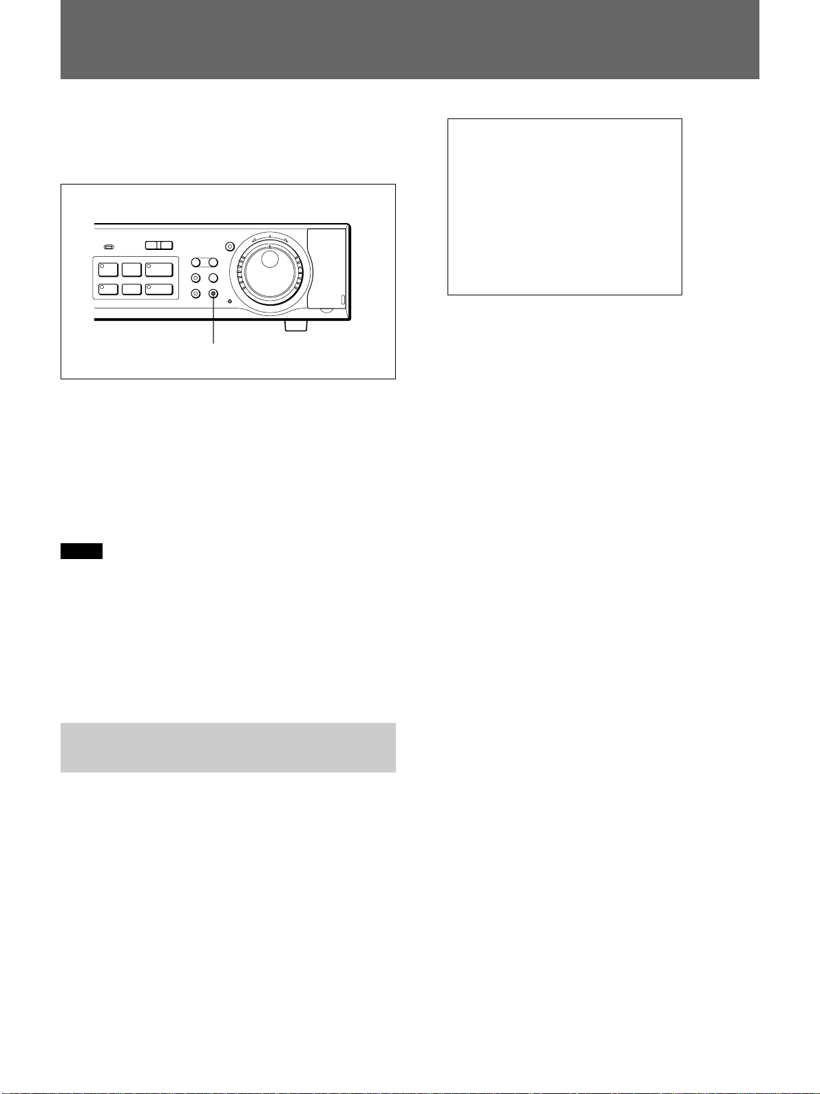
Data Storage
The COPY button enables you to copy data recorded
in the normal and alarm recording areas to the archive
area for data storage.
COPY TO : ARCHIVE AREA
HOW MANY : 20 PICTURES
l
REC
STOP
ALARM
PRE REVERSE PLAY
a REC
-
LOCK
S PAUSE s STOP G PLAY
TIMER
L
SHUTTLE
HOLD
j
N
R
U
SEARCH
FRAME/FIELD
T
E
R
MENU EXIT/OSD
ZOOM
CHANNEL COPY
COPY button and indicator
J
E
N
T
E
R
PUSH
Up to 9999 events of video and audio can be stored in
the archive area. The data copied to the archive area
can further copied to optional memory sticks.
When you have connected a DDS drive via the PC
card slot on the rear, you can back up the entire
archive area.
For connections for data storage, see page 41(GB).
Notes
•If you try to copy data in the normal or alarm
recording area directly to a memory stick, the HSRX200/X200P first copies the data to the archive area,
then to the memory stick.
•If you have specified a certain channel among the
inputs signals from a multiplexer, only the selected
channel will be copied.
Copying Data to the Archive Area or a Memory Stick
1 Set the unit to Playback mode, and when an image
to start copying is displayed, press the X PAUSE
button to switch to Still-Picture mode.
START c
CHANGE WITH JOG, SET WITH SHUTTLE
3 Turn the Shuttle dial clockwise when selecting the
destination of the data on the COPY TO line.
ARCHIVE AREA: To copy the data from the
normal or alarm recording area to the archive
area.
PC CARD: To copy the data to a memory stick.
Select the destination with the Jog dial and turn the
Shuttle dial clockwise to finalize your selection.
The HOW MANY line is highlighted.
4 Turn the Shuttle dial clockwise to specify the
quantity of images to be copied on the HOW
MANY line.
The figure input column flashes.
(1)Set the number with the Jog dial and turn the
Shuttle dial clockwise.
The unit column flashes.
(2)Set the unit with the Jog dial and turn the
Shuttle dial clockwise to register the setting.
PICTURES: To specify the number in units of
picture frames
SECONDS: To specify the number in units of
seconds
MINUTES: To specify the number in units of
minutes
START is highlighted.
2 Press the COPY button.
The indicator of the COPY button lights, and the
copy set display is superimposed on the image.
5 Turn the Shuttle dial clockwise.
Copying begins.
When copying is completed, the indicator of the
COPY button goes dark.
29 (GB)
Page 30

Data Storage
To stop copying in progress
Press the COPY button. The copy operation is
canceled.
When the archive area becomes full
You can clear all the data in the area using
RECORDING AREA SET of MAIN MENU 1.
You cannot delete specific events only.
Backing-up Data on DDS Tape
With a DDS drive, you can back up the entire archive
area on DDS tape and restore it from the tape.
1 Insert the DDS tape in the connected DDS drive.
For details on DDS tape and drive operation, refer to
the instructions of the DDS tape and drive in use.
2 Press the COPY button when the unit is in stop
status or in Recording mode.
The indicator of the COPY button lights, and the
ARCHIVE SET menu appears.
When you have selected RESTORE or ERASE,
a list of data on the tape in the connected DDS
drive is displayed.
Proceed to step 5.
5 Select the data to restore or delete with the Jog
dial, and turn the Shuttle dial clockwise.
A confirmation message is displayed.
6 To execute the restore or delete operation, select
YES (or NO to cancel it) and turn the Shuttle dial
clockwise.
Restoration or deletion begins.
To stop backup in progress
Press the X PAUSE button.
Note that restoration and deletion once started cannot
be stopped.
<ARCHIVE SET>
BACKUP c
RESTORE c
ERASE c
3 Turn the Jog dial to select the operation.
BACKUP: To back up the entire archive area on
DDS tape
RESTORE: To restore data from DDS tape to the
archive area
ERASE: To erase data on DDS tape
Note
When you execute a RESTORE operation, the
current data in the archive area will be lost.
4 Turn the Shuttle dial clockwise.
When you have selected BACKUP, backup
begins.
30 (GB)
Page 31

Playback
Using the B PLAY button or through a search
operation, you can view the recorded images.
Once the playback starts, you may also select highspeed or slow-motion playback in both the forward
and backward directions, still-picture playback, and
frame-by-frame playback in both the forward and
backward directions.
When a multiplexer whose channel information can be
decoded has been connected, channel selection from
this unit is possible.
The pre-reverse playback function permits you to
check the recorded picture without stopping recording
in progress.
For search operations, see “Picture Searching” on page
34(GB).
Buttons and dials for playback operations
B PLAY/PRE REVERSE PLAY button
. ALARM M? buttons
x STOP button
X PAUSE button
SHUTTLE HOLD button
Shuttle dial
Jog dial
Pre-Reverse Playback – Playback During Recording
Press the B PLAY/PRE REVERSE PLAY button
during recording.
While maintaining recording in progress, playback
begins from the point in the normal recording area just
before the specified pre-reverse play time (1 to 99
minutes) from the current time.
If you press the B PLAY/PRE REVERSE PLAY
button shortly after starting recording and the duration
of recorded data in the normal recording area is still
shorter than the specified pre-reverse play time,
playback begins from the starting point of recording.
When playback reaches to the current time, pre-reverse
playback is canceled.
Setting the pre-reverse play time
Use VIDEO INPUT/PRE REVERSE of MAIN
MENU 1.
MENU EXIT/OSD
SEARCH
ZOOM
FRAME/FIELD
CHANNEL COPY
SHUTTLE
HOLD
button
j
N
R
U
T
E
R
J
E
N
T
E
R
PUSH
l
ALARM
-
LOCK
S PAUSE s STOP G PLAY
TIMER
L
PRE REVERSE PLAY
REC
a REC
STOP
ZOOM button SEARCH FRAME/FIELD
Normal Playback
Press the B PLAY button.
The indicator of the button lights, and playback of
pictures recorded on the normal recording area begins
from the oldest recording or the position you have
stopped previous playback operation.
If audio has been recorded, it will be played only when
pictures are being played at the same speed as that
when they were recorded.
When playback reaches the last of the recorded
pictures, the unit automatically enters Still-Picture
mode.
For playback of the alarm recording area and archive area,
see “Picture Searching” on page 34(GB).
To stop playback
Press the x STOP button.
The display switches to the current input image.
1 Press the MENU button to display MAIN MENU 1
on the monitor screen.
2 Turn the Jog dial to highlight 2. VIDEO INPUT/
PRE REVERSE and turn the Shuttle dial
clockwise.
The VIDEO INPUT/PRE REVERSE PLAY
display appears.
<VIDEO INPUT>
MULTIPLEXER : NO USE
<PRE REVERSE PLAY>
PRE REVERSE PLAY TIME : 10 MIN
3 Turn the Jog dial to highlight PRE REVERSE
PLAY TIME line and turn the Shuttle dial
clockwise.
The current PRE REVERSE PLAY TIME setting
flashes.
31 (GB)
Page 32

Playback
4 Turn the Jog dial to set the desired time and turn
the Shuttle dial clockwise to register the setting.
5 To exit the menu, press the EXIT/OSD button.
Still-Picture Playback
During playback, press the X PAUSE button.
The indicator of the X PAUSE button lights, and the
playback picture freezes.
Press the X PAUSE button again to restore normal
playback.
To switch between frame still and field still
When an image recorded in Frame Recording mode is
displayed in Still-Picture mode, pressing the SEARCH
FRAME/FIELD button alternately switches between
frame still and field still.
To advance or reverse the still picture frame
by frame
Using the Jog dial, frame-by-frame playback can be
done in both the forward and reverse directions.
Turning the Jog dial clockwise advances the pictures
frame by frame, and turning it counterclockwise
reverses the pictures frame by frame.
Variable-Speed Playback
The Jog and Shuttle dials enable playback at various
speeds.
Playback will be performed in the direction and speed
indicated by the direction and orientation of the Shuttle
dial.
When you release the dial, the previous mode is
restored.
Direction and
degrees of Shuttle Playback Still-Picture
dial rotation
+70° to +80° 16-time normal 4-time normal
+50° to +70° 8-time normal 2-time normal
+30° to +50° 4-time normal Normal speed
+10° to +30° 2-time normal
+10° to –10° Normal speed Still picture
–10° to –30° Normal speed
–30° to –50° 2-time normal Normal speed
–50° to –70° 4-time normal 2-time normal
–70° to –80° 8-time normal 4-time normal
+: Clockwise rotation
–: Counterclockwise rotation
speed in the speed in the
forward direction forward direction
speed in the speed in the
forward direction forward direction
speed in the in the
forward direction forward direction
1
/2-time normal
speed in the speed in the
forward direction forward direction
in the forward
direction
1
in the reverse speed in the
direction reverse direction
speed in the in the
reverse direction reverse direction
speed in the speed in the
reverse direction reverse direction
speed in the speed in the
reverse direction reverse direction
/2-time normal
With the Jog dial
Using the Jog dial, you may change the playback
speed (playback rate specified in frames per second) in
17 steps.
Set the unit in Playback mode and turn the Jog dial.
If you rotate it clockwise by one notch, the playback
speed increases by one step. One notch
counterclockwise rotation decreases the playback
speed by one step. Press the B PLAY button to
restore normal playback speed.
With the Shuttle dial
Using the Shuttle dial, you may play the pictures at a
high speed or in slow motion.
Set the unit to Playback mode (PLAY button indicator
lit) or Still-Picture mode (PAUSE button indicator
lit) and rotate the Shuttle dial.
32 (GB)
To hold the variable-speed playback
The SHUTTLE HOLD button enables you to lock the
direction and speed obtained with the Shuttle dial.
Turn the Shuttle dial in the desired direction and hold
it at the angle for the desired speed, then press the
SHUTTLE HOLD button so that the indicator of the
SHUTTLE HOLD button lights.
Playback of the direction and speed set by the Shuttle
dial are maintained even after you release the Shuttle
dial.
To restore the previous mode, press the SHUTTLE
HOLD button again.
Page 33

Zooming in on an Image
The image in the zone cursor is enlarged and displayed
full-screen.
The ZOOM button enables you to zoom to a certain
area of the playback picture on the monitor screen.
You may also zoom the camera input in a recording
mode or stop status with the same procedure.
1 Press the ZOOM button.
The zone cursor to specify the area to zoom
appears.
Zone cursor
2 Turn the Jog dial to move the zone cursor
horizontally to the desired position and turn the
Shuttle dial clockwise to register the setting of the
horizontal position.
17-11-01
02:36:00 HI-0.12SEC
In Zoom mode, the indicator of the ZOOM button
lights.
To cancel Zoom mode
Press the ZOOM button again.
Multiplexer Channel Selection
When a multiplexer whose channel information can be
decoded, such as a Sony YS-DX156, has been
connected, you may select a certain channel (camera)
for playback.
1 Set the unit to Still-Picture mode and press the
CHANNEL button.
3 Turn the Jog dial to move the zone cursor
vertically to the desired position and turn the
Shuttle dial clockwise.
The CHANNEL button indicator lights (Channel
Select mode) and the channel input display
appears.
PLEASE SELECT CHANNEL
** CHANNEL
CHANGE WITH JOG, SET WITH SHUTTLE
2 Turn the Jog dial to select the channel (camera
number), and turn the Shuttle dial clockwise to
register your selection.
Channel Select mode is released and the selected
channel is displayed.
To display all multiplexer channels
Press the CHANNEL button again.
33 (GB)
Page 34

Picture Searching
You can find and play back the pictures recorded/
stored on each area of the hard disk.
You may select from among five Search modes.
Buttons and dials for search operations
. ALARM >
buttons
l
REC
STOP
ALARM
PRE REVERSE PLAY
a REC
-
LOCK
S PAUSE s STOP G PLAY
TIMER
L
SEARCH FRAME/FIELD
button
SHUTTLE
HOLD
j
N
R
U
SEARCH
FRAME/FIELD
T
E
R
MENU EXIT/OSD
ZOOM
CHANNEL COPY
Jog dial
J
E
N
T
E
R
Shuttle dial
PUSH
Search Mode Selection
1 Press the SEARCH FRAME/FIELD button.
The SEARCH menu (search mode select display)
appears.
<SEARCH>
ALARM SEARCH c
ALARM THUMBNAIL SEARCH c
TIME/DATE SEARCH c
ARCHIVE AREA SEARCH c
ACTIVITY DETECTION SEARCH c
MOVE:JOG SELECT:SHUTTLE
2 Turn the Jog dial to highlight the desired search
mode.
ALARM SEARCH: To find a picture recorded in
the alarm recording area from the list.
ALARM THUMBNAIL SEARCH: To find a
picture recorded in the alarm recording area by
the thumbnail images.
TIME/DATE SEARCH: To find a picture
recorded in the alarm or normal recording area
by the recording date and time.
ARCHIVE AREA SEARCH: To find a picture
stored in the archive area.
ACTIVITY DETECTION SEARCH: To find a
picture recorded in the alarm or normal
recording area using the built-in activity
detection sensor.
34 (GB)
3 Turn the Shuttle dial clockwise.
The setting display for the selected search mode
appears.
To exit search operations
Press the SEARCH FRAME/FIELD button again.
Page 35

Searching From the Alarm Recording List
Searching by the Thumbnail Image
You can find and play back a picture recorded in the
alarm recording area from the Alarm Recording list.
1 Select ALARM SEARCH on the SEARCH menu.
The ALARM SEARCH display appears, listing the
number, time, and date of alarm recording events.
<ALARM SEARCH>
NO DATE TIME TOTAL ALARMS
0108 12-20 05:37 0234
0107 12-19 14:23
0106 12-16 16:13
0105 12-16 11:13
0104 12-15 10:13
0103 12-13 15:19
0102 12-13 11:15
0101 12-13 11:13
MOVE:JOG SELECT:SHUTTLE
The total number of alarm events recorded in the
alarm recording area is shown below TOTAL
ALARMS.
The list can show up to 8 events at once.
Preview zone
You can find and play back a picture recorded in the
alarm recording area by the thumbnail image.
1 Select ALARM THUMBNAIL SEARCH on the
SEARCH menu.
The ALARM THUMBNAIL SEARCH set display
appears, showing thumbnail images of the latest 9
alarm recording events.
0109 0108 0107
0106 0105 0104
0103 0102 0101
To display the previous 9 events, press the
ALARM . button.
2 Turn the Jog dial to highlight the desired alarm
event.
When one second has elapsed after you highlight,
the thumbnail image of the selected event is
displayed in the preview zone.
3 Turn the Shuttle dial clockwise.
The unit enters Playback mode, and the picture of
the selected event is played full-screen.
You may skip to the previous alarm event with the
ALARM . button and to the next alarm event
with the ALARM > button.
2 Turn the Jog dial so that the number of the desired
event flashes.
3 Turn the Shuttle dial clockwise.
The unit enters Playback mode, and the picture of
the selected event is played full-screen.
You may skip to the previous alarm event with the
ALARM . button and to the next alarm event
with the ALARM > button.
35 (GB)
Page 36

Picture Searching
Searching by the Time/Date of Recording
You can find and play back a picture recorded on the
normal or alarm recording area at the specified time
and date.
1 Select TIME/DATE SEARCH on the SEARCH
menu.
The TIME/DATE SEARCH display appears
<TIME DATE SEARCH>
RECORDING TOP : 12-15-00 08:00
RECORDING END : 12-22-00 17:00
SEARCH :
DATE TIME
12-20-00 05:37
PREVIEW c
VIEW c
CHANGE:JOG SET:SHUTTLE
Preview zone
The date and time of the oldest recording is
displayed on the RECORDING TOP line, and that
of the latest one is on the RECORDING END line.
2 Specify the recording date and time of the picture
to be found.
Set the value with the Jog dial and turn the Shuttle
dial clockwise to move to the next column (turn it
counterclockwise to return).
To preview the picture as a thumbnail image
Highlight PREVIEW and turn the Shuttle dial
clockwise.
The unit searches for the event recorded at the date and
time you specified and displays its thumbnail image in
the preview zone.
If there is no event recorded at the specified date/time,
the image from the closest date and time is displayed.
The unit searches the alarm recording area first, then
the normal recording area.
Searching on the Archive Area
You can find and play back the pictures stored in the
archive area.
1 Select ARCHIVE AREA SEARCH on the
SEARCH menu.
The ARCHIVE AREA SEARCH display appears,
showing the list of the picture group stored in the
archive area.
Each group is listed with its number, date and the
time of the first picture.
<ARCHIVE AREA SEARCH>
NO DATE START CAPACITY
0011 12-13 11:13 TOTAL - 1024MB
0012 12-13 11:15 USED - 400MB
0013 12-13 15:19
0014 12-15 10:13
0015 12-16 16:13
0016 12-16 11:13
0017 12-19 14:23
0018 12-20 05:37
MOVE:JOG SELECT:SHUTTLE
Preview zone
The total size and used size of the archive area are
displayed under CAPACITY.
The list can display up to 8 groups at once.
2 Turn the Jog dial to highlight the desired picture
group.
When one second has elapsed after you highlight,
the thumbnail image of the first picture of the
selected group is displayed in the preview zone.
3 Turn the Shuttle dial clockwise.
The unit enters Playback mode, and the pictures of
the selected group are played full-screen.
To display the picture full-screen
Highlight VIEW and turn the Shuttle dial clockwise.
The unit enter Playback mode with full-screen display,
starting from the picture recorded at the specified date
and time.
36 (GB)
Page 37

Searching using the Activity Detection Sensor
The built-in activity detection sensor permits you to
find and play back the picture for which activity
(change in luminance) has been detected within the
specified period.
You can search both the normal and alarm recording
areas.
<ACTIVITY DETECTION SEARCH>
SEARCH FROM : ALARM /CHANNEL: --
START:
12-20-00 08:00
END:
12-20-00 10:00
ACTIVITY SENSOR c
PREVIEW c
VIEW c
MOVE/CHNG:JOG SET:SHUTTLE
Preview zone
1 Select ACTIVITY DETECTION SEARCH on the
SEARCH menu.
The ACTIVITY DETECTION SEARCH display
appears.
<ACTIVITY DETECTION SEARCH>
SEARCH FROM : ALARM
START : 12-20-00 08:00
END : 12-20-00 10:00
CHANNEL : --
START PREVIEW c SEARCHING
MOVE:JOG SELECT:SHUTTLE
2 Turn the Shuttle dial clockwise to specify the area
to search on the SEARCH FROM line.
The current setting flashes.
3 Select the area(s) with the Jog dial and turn the
Shuttle dial clockwise to finalize your selection.
ALARM: To search the alarm recording area only
NORMAL: To search the normal recording area
only
ALARM & NORMAL: To search both the alarm
and normal recording areas. The unit searches
the alarm recording area first, then the normal
recording area.
6 Set the starting date and time of the period for
searching at START.
7 Set the ending date and time of the period for
searching at END.
8 To set the activity detection sensor, highlight
ACTIVITY SENSOR and turn the Shuttle dial
clockwise.
The sensor marks are displayed on a 10 × 8 grid on
the monitor, and the top left mark flashes.
You may set the sensing points and the sensitivity.
For the setting procedure, see “Setting the activity
detection sensor” on page 25(GB).
To preview the thumbnail images
Highlight PREVIEW and turn the Shuttle dial
clockwise.
Each time you turn the Shuttle dial clockwise, the unit
searches for events recorded during the specified
period and displays in sequence thumbnail images of
the pictures for which activity was detected in the
preview zone.
To display a picture full-screen
Highlight VIEW and turn the Shuttle dial clockwise.
The unit enters Playback mode with full-screen
display, starting from the picture displayed in the
preview zone as a thumbnail image.
4 If a multiplexer of the specified type is in use,
specify the channel on the CHANNEL line.
5 Highlight START PREVIEW and turn the Shuttle
dial clockwise.
The display changes and the thumbnail image of
the oldest picture recorded in the specified area(s)
is displayed in the preview zone.
37 (GB)
Page 38

Connections and Settings
Turn off the power to all the units to be connected.
Connect the power cords only after completing all
other connections.
Note
This unit has no power switch. When you connect AC
power using the supplied AC power cord, the unit is
turned on, and all the indicators on the front panel
flash during the starting process.
Basic Connection Example
Video camera
VIDEO OUT
Microphone
VIDEO
AUDIO
OUTLOOP OUT IN OUTLOOP OUT
S-VIDEO VIDEO
IN
VIDEO
OUT
PC CARD
MIC
MIC
AUDIO
OUT
ININOUT
When connecting a video monitor having S-VIDEO
input/output, you can use S-VIDEO IN/S-VIDEO
OUT in place of VIDEO IN/VIDEO OUT.
If there are inputs both to the VIDEO IN and
S-VIDEO IN, that to S-VIDEO IN has priority.
HSR-X200/X200P
NON REC OUT
CLOCK
ALARM
RESET
IN INOUT OUT
COMCOM
AB
RS485
REMOTE
RS485
TERMINATE
IN OUTCOM COMCOMCOM COM
SERIES
ON
OFF
RS-232C
AC power cord
(supplied)
VIDEO IN
AUDIO IN
Video monitor
WARNING OUT
ALARM
FULL
FULL
SW OUT
-AC IN
to an AC outlet
Series Connections and Associated Settings
Connecting multiple HSR-X200/X200P units in series
enables series recording.
Connection example
Video camera
VIDEO OUT
Microphone
First
HSR-X200/
X200P
MIC
PC CARD
Second
HSR-X200/
AUDIO
X200P
PC CARD
Last
HSR-X200/
X200P
AUDIO
PC CARD
MIC
AUDIO
OUT
IN
MIC
AUDIO
OUT
IN
MIC
AUDIO
OUT
AUDIO
ININOUT
AUDIO
ININOUT
AUDIO
ININOUT
VIDEO IN
OUTLOOP OUT IN OUTLOOP OUT
S-VIDEO VIDEO
VIDEO
IN
OUTLOOP OUT IN OUTLOOP OUT
S-VIDEO VIDEO
VIDEO
IN
OUTLOOP OUT IN OUTLOOP OUT
S-VIDEO VIDEO
VIDEO
OUT
LOOP
OUT
VIDEO
LOOP
OUT
VIDEO
OUT
OUT
RS-232C
ALARM
OUT
+ COM
ALARM
IN
+ COM
RS-232C
ALARM
OUT
+ COM
ALARM
IN
+ COM
RS-232C
VIDEO IN 1
VIDEO IN 2
VIDEO IN 3
AUDIO IN
WARNING OUT
NON REC OUT
CLOCK
ALARM
ALARM
RESET
FULL
FULL
IN INOUT OUT
COMCOM
IN OUTCOM COMCOMCOM COM
AB
SW OUT
REMOTE
SERIES
RS485
RS485
TERMINATE
ON
OFF
SERIES
OUT
+ COM
to an AC outlet
SERIES
IN + COM
WARNING OUT
NON REC OUT
CLOCK
ALARM
ALARM
RESET
FULL
IN INOUT OUT
FULL
COMCOM
IN OUTCOM COMCOMCOM COM
AB
REMOTE
SW OUT
SERIES
RS485
RS485
TERMINATE
ON
OFF
SERIES
OUT
+ COM
to an AC outlet
SERIES
IN + COM
WARNING OUT
NON REC OUT
CLOCK
ALARM
ALARM
RESET
FULL
IN INOUT OUT
FULL
COMCOM
IN OUTCOM COMCOMCOM COM
AB
REMOTE
SW OUT
SERIES
RS485
RS485
TERMINATE
ON
OFF
to an AC outlet
Video monitor
-AC IN
-AC IN
-AC IN
38 (GB)
Page 39

Settings
To activate series recording, set each of the connected
HSR-X200/X200P units as follows with 4.
RECORDING CONDITIONS SET of MAIN MENU
1.
For details on menu operations, see “Menu Operations” on
page 17(GB).
Multiplexer Connection and Associated Settings
Connection example
<RECORDING CONDITIONS SET>
SERIES RECORDING : OFF
NORMAL RECORDING AREA
OVERWRITE : OFF
ALARM RECORDING AREA
OVERWRITE : OFF
REMAINING DISK WARNING : 1%
Set SERIES RECORDING to ON.
Set OVERWRITE to OFF for both NORMAL
RECORDING AREA and ALARM RECORDING
AREA.
For details on OVERWRITE, see “Recording Area Settings”
on page 46(GB).
Notes
•Series recording cannot be performed if timer
recording has been specified.
Be sure that the TIMER button indicator is dark on
all the connected HSR-X200/X200P units.
•If the OVERWRITE function is set to ON on any of
the connected HSR-X200/X200P units, recording
will be continued on that unit.
To start series recording
Press the z REC button on the first HSR-X200/
X200P.
Multiplexer
VIDEO
IN
AUDIO
MIC
ININOUT
PC CARD
S-VIDEO VIDEO
HSR-X200/X200P
OUTLOOP OUT IN OUTLOOP OUT
VCR INVCR OUT
VIDEO
OUT
ALARM
COM
+ IN
RS-232C
AL
NON REC OUT
ALARM
RESET
IN INOUT OUT
AB
RS485
ALARM
COM
+ OUT
CLOCK
COMCOM
IN OUTCOM COMCOMCOM COM
REMOTE
SERIES
RS485
TERMINATE
ON
OFF
WARNING OUT
SW OUT
+ COM
ALARM
FULL
FULL
SW OUT
SW+ C
-AC IN
to an AC outlet
Settings
Specify the type of the connected multiplexer with
2. VIDEO INPUT/PRE REVERSE of MAIN MENU
1.
For details on menu operations, see “Menu Operations” on
page 17(GB).
<VIDEO INPUT>
MULTIPLEXER : NO USE
<PRE REVERSE PLAY>
PRE REVERSE PLAY TIME : 10 MIN
SONY: Sony-made multiplexer (YS-DX516, etc.)
OTHERS1: Sanyo-made multiplexer
OTHERS2: Multiplexer of other manufacturers,
including Dedicated Micro and Robot
NO USE: Not to use any multiplexer
39 (GB)
Page 40

Connections and Settings
Network Connections and Associated Settings
Insert a commercially available LAN card (10BASE-T
or 100BASE-T) into the PC CARD slot on the rear
panel, and connect the unit to your network via the
card.
Connection
HSR-X200/X200P
AUDIO
MIC
ININOUT
PC CARD
PC CARD
LAN card
OUTLOOP OUT IN OUTLOOP OUT
S-VIDEO VIDEO
LAN CARD: Select the type of your LAN card.
LAN1: FEtherPCC-TXD or equivalent
LAN2: FEtherPCC-TD or equivalent
NETWORK CONTROL: Set to ON to enable
controls via the network.
IP ADDRESS: Set the address to be used to access
this unit.
For effective addresses, ask your system
administrator.
SUBNET MASK/GATEWAY: Set the values
according to the network to be connected.
PASSWORD SET: Set the passwords for network
access (4 to 8 alphanumeric characters).
You can specify three levels of passwords, i.e. ID1,
ID2, and ID3, differing in operable functions.
ID1: Only monitoring the camera input and
playback images and stopping playback in
progress are allowed.
ID2: Operations related to playback and data
storage are allowed. Recording and menu
operations are not allowed.
ID3: All the operations using the buttons displayed
on the browser window are allowed.
ETHERNET
Ethernet cable
Settings
Perform the necessary settings with 5. NETWORK
SET of MAIN MENU 2.
For details on menu operations, see “Menu Operations” on
page 17(GB).
<NETWORK SET>
LAN CARD : LAN1
NETWORK CONTROL : ON
IP ADDRESS : 192.168. 0. 1
SUBNET MASK : 255.255.255.000
GATEWAY : 0.0.0.0
PASSWORD SET
ID PASSWORD (4-8)
ID1 : 1111--- ID2 : 2222--- ID3 : 3333----
40 (GB)
Page 41

Connections for Data Storage
RS-232C
RS-232C
IN INOUT OUT
WARNING OUT
CLOCK
NON REC OUT
ALARM
RESET
FULL
ALARM
FULL
ON
RS485
TERMINATE
OFF
-AC IN
COMCOM
AB
IN OUTCOM COMCOMCOM COM
REMOTE
RS485
SERIES
SW OUT
Connections for Remote Control and Associated Settings
Memory stick
Inserting a commercially available PC card adaptor
into the PC card slot on the front panel enables data
copying to memory sticks.
HSR-X200/X200P
SHUTTLE
HOLD
j
N
R
U
T
E
R
J
E
N
T
E
R
PC card adaptor
Memory stick
Open the cover of the slot
by pressing the lower right
corner.
DDS (Digital Data Storage) drive
Insert a commercially available FAST SCSI card into
the PC card slot on the rear panel.
A DDS drive (DDS-2 or DDS-3 type) can be
connected, enabling backup and restoration of data in
the archive area.
SCSI card: ADAPTEC SlimSCSI 1460 or equivalent
Remote control via the RS-232C or RS-485 interface,
or with a special circuit connected to the REMOTE
terminal, is possible
Connection examples
RS-232C connector
HSR-X200/X200P
to RS-232C
(D-sub 9-pin)
9-pin D-sub cable
(optional)
Computer
HSR-X200/X200P
MIC
PC CARD
PC CARD
FAST SCSI card
AUDIO
ININOUT
OUTLOOP OUT IN OUTLOOP OUT
S-VIDEO VIDEO
SCSI
DDS drive
Pin arrangement of the RS-232C connector
(D-sub 9-pin)
1 5
6
9
Pin No. Signal Function Signal direction
2 RxD Data reception PC t HSR
3 TxD Data transmission HSR t PC
5 GND Signal ground
7 RTS Request to send HSR t PC
41 (GB)
Page 42

Connections and Settings
RS-485 terminals REMOTE terminal
If you make a remote controller and connect it to the
REMOTE terminal, use the layout shown below. Set
Push in to insert cables.
the input to LOW.
Controller
AB
REMOTE
RS485
RS485
TERMINATE
ON
OFF
Twisted-pair cable
RS-485
RS485
(COM - A - B)
RS-232C
RS485
(COM - A - B)
RS485
(COM - A - B)
RS-232C
IN OUTCOM COMCOMCOM COM
SW OUT
SERIES
to B signal
to A signal
Ground (COM)
First HSR-X200/X200P
WARNING OUT
NON REC OUT
CLOCK
ALARM
RESET
IN INOUT OUT
AB
REMOTE
RS485
RS485
TERMINATE
ALARM
FULL
FULL
COMCOM
IN OUTCOM COMCOMCOM COM
SERIES
ON
OFF
-AC IN
SW OUT
RS485 TERMINATE:
Set to OFF.
Last HSR-X200/X200P
WARNING OUT
NON REC OUT
CLOCK
ALARM
RESET
IN INOUT OUT
AB
REMOTE
RS485
RS485
TERMINATE
ALARM
FULL
COMCOM
FULL
-AC IN
IN OUTCOM COMCOMCOM COM
SW OUT
SERIES
ON
OFF
RS485 TERMINATE:
Set to ON only on the last
unit.
HSR-X200/X200P
RS-232C
WARNING OUT
NON REC OUT
CLOCK
ALARM
RESET
IN INOUT OUT
AB
REMOTE
RS485
RS485
TERMINATE
ALARM
COMCOM
FULL
FULL
IN OUTCOM COMCOMCOM COM
SW OUT
SERIES
ON
OFF
REMOTE
220Ω
SW1 : REC STOP
220Ω
SW2 : PLAY STOP
300Ω
SW3 : PAUSE
360Ω
SW4 : SEARCH
470Ω
SW5 : CHANNEL
680Ω
SW6 : PLAY
820Ω
SW7 : REC
1.2kΩ
SW8 : MENU
1.8kΩ
SW9 : EXIT/OSD
2.2kΩ
SW10 : SPEED/DATA v
3.3kΩ
SW11 : SPEED/DATA V
4.7kΩ
SW12 : CURSOR B
7.5kΩ
SW13 : CURSOR b
13kΩ
SW14 : ZOOM
27kΩ
SW15 : COPY
68kΩ
SW16: TIMER
-AC IN
42 (GB)
Page 43

Settings
When using the RS-232C or RS-485 interface, perform
the necessary settings with 2. RS-232C/RS-485 SET of
MAIN MENU 2.
For details on menu operations, see “Menu Operations” on
page 17(GB).
<RS-232C/RS-485 SET>
CONTROL : RS-232C
DATA SPEED : 19200
STATUS INFO : ON
ALARM INFO : ON
ADDRESS : 000
CONTROL: Select RS-232C or RS-485.
DATA SPEED: Select the transmission speed from
among 2400/4800/9600/19200.
STATUS INFO: Set to ON when transmitting status
information of this unit.
ALARM INFO: Set to ON when transmitting alarm
information of this unit.
ADDRESS: Set the address (1 to 127) when using RS-
485.
For the RS-232C or RS-485 interface commands, see the
command table on page 62(GB).
Hard Disk Expansion and Mirroring Setting
An optional HSBK-X201 hard disk drive (80 GB) can
be added for built-in hard disk expansion.
For mounting the HSBK-X201, ask your Sony dealer.
Initializing the hard disk
When you add a hard disk, it must be initialized.
Use 6. HDD SET of MAIN MENU 2.
For details on menu operations, see “Menu Operations” on
page 17(GB).
<HDD SET>
DISK 1 : 80GB
DISK 2 : --GB
DISK INITIALIZE c
CAUTION : ALL RECORDING WILL BE ERASED!
MIRRORING : OFF
PLAYBACK DRIVE : DISK 1
CAUTION : RECORDING SPEED WILL BE
LIMITED BY MIRRORING!
Highlight DISK INITIALIZE and turn the Shuttle dial
clockwise.
Initializing begins.
When initializing is completed, the size of the added
disk is displayed on the DISK 2 line.
Activating the mirroring function
When the unit is equipped with two hard disks, the
mirroring function to record the same data on both of
the disks can be activated.
MIRRORING: Set to ON to activate the mirroring
function.
PLAYBACK DRIVE: Select the drive from which to
read the data for playback if data are recorded on
both drives with the mirroring function.
Note
In mirroring, the available maximum recording cycle
will be halved. When you set MIRRORING to ON, a
confirmation message is displayed.
When you select YES to turn on mirroring, the
recording cycles you can select when setting the
recording conditions will be limited.
43 (GB)
Page 44

Preparations
The HSR-X200/X200P permits you to perform the
preparatory settings required for recording and
playback using menus.
For details on menu operations, see “Menu Operations” on
page 17(GB).
OSD Language Selection
You may select the language for on-screen displays,
such as menus and messages, from among English,
French, German (HSR-X200P only) and Spanish.
Use LANGUAGE/CLOCK SET of the MAIN
MENU 1.
1 Press the MENU button to display MAIN
MENU 1.
2 Select 1. LANGUAGE/CLOCK SET by turning
the Shuttle dial clockwise.
The LANGUAGE/CLOCK SET display appears
and the current language setting is highlighted.
<LANGUAGE/LANGUE/SPRACHE/IDIOMA>
ENGLISH
<CLOCK SET>
22-01-2001 MON 09:01:00
<SUMMER TIME SET>
MODE : NO USE
WEEK MONTH TIME
ON LST-SUN O3 02:00
0FF LST-SUN 10 02:00
<EXT. CLOCK SET>
ADJUST. TIME : 01:00
3 Turn the Shuttle dial clockwise.
The current language setting flashes.
4 Turn the Jog dial to select the desired language and
turn the Shuttle dial clockwise.
Clock Adjustment
Adjust the built-in clock to your local time.
Use the same LANGUAGE/CLOCK SET of MAIN
MENU 1 as with the language selection.
You may also perform the settings for summer time
(daylight savings time) and clock adjustment using the
CLOCK IN/OUT terminals.
Adjusting the clock
1 Turn the Jog dial to highlight the current setting of
CLOCK SET and turn the Shuttle dial clockwise.
The leftmost column flashes.
<LANGUAGE/LANGUE/SPRACHE/IDIOMA>
ENGLISH
<CLOCK SET>
22-01-2001 MON 09:01:00
<SUMMER TIME SET>
MODE : NO USE
WEEK MONTH TIME
ON LST-SUN O3 02:00
0FF LST-SUN 10 02:00
<EXT. CLOCK SET>
ADJUST. TIME : 01:00
2 Turn the Jog dial to set the month (HSR-X200)/day
(HSR-X200P) and turn Shuttle dial clockwise.
The next day (HSR-X200)/month (HSR-X200P)
column flashes.
3 Similarly, set the day (HSR-X200)/month (HSR-
X200P), year, hours and minutes in the sequence.
The day of the week is automatically set.
The seconds are reset to 0 when you set the
minutes.
Activating summer (daylight savings) time
5 To exit the menu, press the EXIT/OSD button.
44 (GB)
The clock will be automatically switched to summer
(daylight savings) time if you set MODE for
DAYLIGHT SAVINGS (HSR-X200)/SUMMER
TIME SET (HSR-X200P) to USE.
1 Turn the Jog dial to highlight the MODE line and
turn the Shuttle dial clockwise.
NO USE (the current setting) flashes.
Page 45

2 Turn the Jog dial to set to USE and turn the Shuttle
dial clockwise.
3 Set when to switch to summer (daylight savings)
time on the ON line.
WEEK: What day of which (first, second, third,
fourth, or last) week in the specified month on
which to switch
MONTH: Month in which to switch
TIME: Time (hours:minutes) when to switch
CLOCK IN/OUT connection examples
1: When adjusting the time by using an external
switch
External switch
4 Similarly set when to return to the standard time on
the OFF line.
Adjusting the time using the CLOCK IN/
OUT terminals
To adjust the built-in clock of this unit and/or the
clocks of another connected HSR-X200/X200P units
using the CLOCK IN/OUT terminals on the rear panel,
set the hours and minutes for ADJUST. TIME of EXT.
CLOCK SET.
The output at the CLOCK OUT terminal will drop to
0 V at the time you specify here.
When the CLOCK IN terminal is short-circuited to the
COM terminal, the built-in clock will be set to the time
you specify here, and the output at the CLOCK OUT
terminal will drop to 0 V at the same time.
Be sure to set ADJUST. TIME of EXT. CLOCK SET
to the same time on all the connected HSR-X200/
X200P units.
When the settings are completed
Press the EXIT/OSD button to exit the menu.
HSR-X200/X200P
RS-232C
HSR-X200/X200P
RS-232C
HSR-X200/X200P
RS-232C
NON REC OUT
ALARM
RESET
IN INOUT OUT
COMCOM
AB
REMOTE
RS485
RS485
TERMINATE
ON
OFF
COM
NON REC OUT
ALARM
RESET
IN INOUT OUT
COMCOM
AB
REMOTE
RS485
RS485
TERMINATE
ON
OFF
COM
COM
NON REC OUT
ALARM
RESET
IN INOUT OUT
COMCOM
AB
REMOTE
RS485
RS485
TERMINATE
ON
OFF
CLOCK
INCOM
WARNING OUT
CLOCK
IN OUTCOM COMCOMCOM COM
SERIES
CLOCK
OUT
CLOCK
INCOM
WARNING OUT
CLOCK
IN OUTCOM COMCOMCOM COM
SERIES
CLOCK
OUT
CLOCK
IN
WARNING OUT
CLOCK
IN OUTCOM COMCOMCOM COM
SERIES
FULL
SW OUT
FULL
SW OUT
FULL
SW OUT
ALARM
FULL
ALARM
FULL
ALARM
FULL
-AC IN
-AC IN
-AC IN
45 (GB)
Page 46

Preparations
2: When adjusting the time by using the clock of
the first unit as the master
HSR-X200/X200P
(Master unit)
RS-232C
HSR-X200/X200P
RS-232C
HSR-X200/X200P
RS-232C
NON REC OUT
ALARM
RESET
IN INOUT OUT
COMCOM
AB
REMOTE
RS485
RS485
TERMINATE
ON
OFF
COM
NON REC OUT
ALARM
RESET
IN INOUT OUT
COMCOM
AB
REMOTE
RS485
RS485
TERMINATE
ON
OFF
COM
COM
NON REC OUT
ALARM
RESET
IN INOUT OUT
COMCOM
AB
REMOTE
RS485
RS485
TERMINATE
ON
OFF
WARNING OUT
CLOCK
IN OUTCOM COMCOMCOM COM
SERIES
CLOCK
OUT
CLOCK
INCOM
WARNING OUT
CLOCK
IN OUTCOM COMCOMCOM COM
SERIES
CLOCK
OUT
CLOCK
IN
WARNING OUT
CLOCK
IN OUTCOM COMCOMCOM COM
SERIES
FULL
SW OUT
FULL
SW OUT
FULL
SW OUT
ALARM
FULL
ALARM
FULL
ALARM
FULL
-AC IN
-AC IN
-AC IN
Recording Area Settings
Of the built-in hard disk, 80% is assigned to the
normal recording area, 19% to the alarm recording
area, and 1% to the archive area as the defaults.
You may change this assignment and reset the areas
with a menu operation.
For the normal recording and alarm recording areas,
you can also set whether to overwrite the data or stop
recording when the area becomes full.
Changing the size of an area
You can change the percentages of areas using
RECORDING AREA SET of MAIN MENU 1.
Note
When you change the area assignment, the previous
data will be lost.
1 Press the MENU button to display MAIN
MENU 1.
2 Select 3. RECORDING AREA SET.
The RECORDING AREA SET display appears,
showing the current settings.
<RECORDING AREA SET>
TOTAL CAPACITY : 80GB
NORMAL RECORDING AREA : 80%
AREA FULL RESET c
ALARM RECODING AREA : 19%
AREA FULL RESET c
ARCHIVE AREA : 1%
AREA FULL RESET c
46 (GB)
CAUTION : WHEN THE AREA SETTING IS CHANGED,
THE WHOLE AREA WILL BE INITIALIZED !
3 Turn the Jog dial to highlight the area to be
changed, and turn the Shuttle dial clockwise to
finalize your selection.
The current value of the selected area flashes.
4 Turn the Jog dial to select the desired value and
turn the Shuttle dial clockwise to register the
setting.
You may set the normal recording area and the
alarm recording area independently.
Page 47

The total value of the areas must be 99%.
The percentage of the archive area is automatically
calculated (in the range of 1 to 15 % according to
the values of the normal recording and the alarm
recording areas.
A confirmation message is displayed.
5 To execute the change, select YES and turn the
Shuttle dial clockwise.
<RECORDING CONDITIONS SET>
SERIES RECORDING : OFF
NORMAL RECORDING AREA
OVERWRITE : OFF
ALARM RECORDING AREA
OVERWRITE : OFF
REMAINING DISK WARNING : 1%
To cancel, select NO.
Resetting an area
You may clear all the data in an area by a reset
operation.
Notes
The normal and alarm recording areas can be reset
only when the OVERWRITE function (see the next
paragraph) is OFF.
You cannot delete specific events only.
1 Highlight the AREA FULL RESET line of the area
you wish to reset on the RECORDING AREA SET
display and turn the Shuttle dial clockwise.
A confirmation message appears.
2 To execute the reset, select YES and turn the
Shuttle dial clockwise.
To cancel, select NO.
Overwriting a recording area
For the normal recording and alarm recording areas,
you can set whether to overwrite the data or stop
recording when the area becomes full.
Use RECORDING CONDITIONS SET of MAIN
MENU 1.
You may also set the warning status when the
remaining capacity of a recording area becomes close
to the end.
3 Turn the Jog dial to highlight the OVERWRITE
line of the area to be set and turn the Shuttle dial
clockwise.
The current setting (default: OFF) flashes.
4 To overwrite, set OVERWRITE to ON and turn
the Shuttle dial clockwise.
Changing the percentage to warn the
remaining
When OVERWRITE is OFF, the FULL or ALARM
FULL indicator on the front panel will flash and an
alarm signal will be output from the FULL or ALARM
FULL terminal if the remaining capacity of the normal
or alarm recording area drops to a certain percentage.
This value is set to 1% in the default setting.
You can change it on the RECORDING
CONDITIONS SET display.
1 Turn the Jog dial to highlight the REMAINING
DISK WARNING line and turn the Shuttle dial
clockwise.
The current setting (default: 1) flashes.
2 Turn the Jog dial to set the desired value and turn
the Shuttle dial clockwise.
The value can be selected in the range of 1 to 10%.
When the settings are completed
Press the EXIT/OSD button to exit the menu.
1 Press the MENU button to display MAIN
MENU 1.
2 Select 4. RECORDING CONDITIONS SET.
The RECORDING CONDITIONS SET display
appears, displaying the current settings.
47 (GB)
Page 48

Preparations
On-Screen Data Selection
You may independently turn on/off the on-screen data
superimposed on the images on the monitor screen.
Use DISPLAY/VIDEO LOSS SET of MAIN
MENU 2.
For details on the on-screen data items, see “On-Screen
Data” on page 16(GB).
1 Press the MENU button to display MAIN MENU 1
and press the MENU button again to switch to
MAIN MENU 2.
2 Select 1. DISPLAY/VIDEO LOSS SET.
The DISPLAY/VIDEO LOSS SET display
appears.
<DISPLAY SET>
DATE : ON
TIME : ON
QUALITY : ON
REC CYCLE : ON
ALARM COUNT : ON
ALARM TYPE : ON
Buzzer Settings
You may independently turn on/off the buzzers for
warning.
Use BUZZER SET of MAIN MENU 2.
1 Press the MENU button to display MAIN MENU 1
and press the MENU button again to switch to
MAIN MENU 2.
2 Select 3. BUZZER SET.
The BUZZER SET display appears.
<BUZZER SET>
ALARM : ON
DISK FULL : ON
DISK ERROR : ON
LOCK WARNING : ON
KEY IN : OFF
NON REC : OFF
<VIDEO LOSS SET>
VIDEO LOSS : ON
3 Highlight the item to be set and turn Shuttle dial
clockwise.
The current setting flashes.
4 Turn the Jog dial to change the ON/OFF setting
and turn the Shuttle dial clockwise to register your
setting.
Repeat steps 3 and 4 for each item to be set.
By setting VIDEO LOSS to ON, a warning
message will be displayed on the monitor screen if
no video input signal is supplied to the unit.
5 When the settings are completed, press the EXIT/
OSD button to exit the menu.
ALARM: Buzzer that sounds when an alarm is
generated
DISK FULL: Buzzer that sounds when the
remaining of the normal recording or alarm
recording area drops below the specified value.
DISK ERROR: Buzzer that sounds when an error
is generated for the hard disk
LOCK WARNING: Buzzer that sounds when an
operation key is pressed with the security lock
active.
KEY IN: Buzzer that sounds when an operation
key is pressed
NON REC: Buzzer that sounds when recording is
interrupted
3 Highlight the buzzer to be set and turn Shuttle dial
clockwise.
The current setting flashes.
4 Turn the Jog dial to change the ON/OFF setting
and turn the Shuttle dial clockwise to register your
setting.
48 (GB)
Repeat steps 3 and 4 for each buzzer to be set.
5 When the settings are completed, press the EXIT/
OSD button to exit the menu.
Page 49

Security Lock Settings
You can activate the security lock on operation by
setting passwords.
Use SECURITY LOCK SET of MAIN MENU 2.
1 Press the MENU button to display MAIN MENU 1
and press the MENU button again to switch to
MAIN MENU 2.
6 Select the lock level for recording operations on
the REC CONTROL line.
USER: Not only administrators, but also users
may perform recording operations.
ADMIN: Only administrators may perform
recording operations. Users are permitted to
perform playback operations only.
Turn the Jog dial to select, and turn the Shuttle dial
clockwise to register your setting.
2 Select 4. SECURITY LOCK SET.
The SECURITY LOCK SET display appears.
<SECURITY LOCK SET>
LEVEL PASSWORD(4-8) USE
ADMIN AJE23535 OFF
USER 1593 OFF
REC CONTROL : ADMIN
The validity of the security lock depends on the
USE ON/OFF and REC CONTROL settings (see
the table below).
3 Set the ADMIN (administrator) password.
The password can be a character string of 4 to 8
alphanumerics.
Turn the Jog dial to select a character and turn the
Shuttle dial clockwise to advance to the next.
4 To validate the ADMIN password, set USE OFF to
ON and turn the Shuttle dial clockwise.
Setting USE to ON on the ADMIN line enables
you to set the USER password.
5 Set the USER password in the same manner as the
ADMIN password and set USE OFF to ON and
turn the Shuttle dial clockwise to validate the
USER password
Note
You cannot set only USER USE to ON. When you
set ADMIN USE to OFF, USER USE is also set to
OFF.
7 To exit the menu, press he EXIT/OSD button.
To activate the security lock
After exiting Menu mode, hold the SHUTTLE HOLD
button pressed for more than 3 seconds.
The security lock with the specified conditions
becomes active, and the LOCK indicator lights.
Note
You cannot activate the security lock when the unit is
in Playback mode.
When the security lock is active
The operations are limited depending on the menu
settings, as follows:
ADMIN
USE USE
ON ON ADMIN All operations are locked.
ON ON USER All operations are locked.
ON OFF ADMIN Only recording and menu
ON OFF USER Only menu operations are
OFF OFF ADMIN All operations are allowed. This
OFF OFF USER All operations are allowed.
When a password input is required, a buzzer will
sound, and the password input display will appear on
the monitor screen.
USER REC Security lock validity
CONTROL
Entering the USER password will
enable playback operations only.
Entering the ADMIN password
will enable all operations.
Entering the USER password will
enable playback AND recording
operations. Entering the ADMIN
password will enable all
operations.
operations are locked, and
playback operations are allowed.
Entering the ADMIN password
will enable all operations.
locked, and recording and
playback operations are allowed.
Entering the ADMIN password
will enable all operations.
is the default condition.
49 (GB)
Page 50

Web Operations
The HSR-X200/X200P can be connected to a network
via an optional network card and operated through the
network.
Operational conditions
To operate the HSR-X200/X200P via a network, use
under the following conditions.
PC: Pentium III 400 MHz, 64 MB or more
OS: Windows 95/Windows 98/Windows Me/
Windows NT 4.0 ServicePack 5 or higher/
Windows 2000
Web browser: Internet Explorer 5.0 or higher
For the connections and the preparatory settings on the
HSR-X200/X200P, see “Network Connection and
Associated Settings” on page 40(GB).
Accessing the Recorder
1 Start Internet Explorer.
2 Type the following in the Address box and press
the Enter key.
http://<
The IP address for the HSR-X200/X200P is the
one that has been set with NETWORK SET of
MAIN MENU 2.
The Network Password input window opens.
IP address for the HSR-X200/X200P
>/
3 Type ID1, ID2, or ID3 in the ID box and the
corresponding password set with NETWORK SET
in the Password box.
Notes
The operations via the network are limited
depending on the password you entered.
If you accessed with the password for ID1: You
are enabled only to view the current camera
input.
If you accessed with the password for ID2: You
are enabled to view the current camera input or
playback picture and perform operations related
to playback and data storage. Recording and
menu operations are not allowed.
If you accessed with the password for ID3: You
are enabled to perform operations using all the
browser buttons.
If you accessed with ID1 or ID2 and try to perform
an operation not allowed, a warning message will
be displayed.
4 Click on OK.
When the password is verified, the SELECT
LANGUAGE display for the HSR-X200/X200P is
displayed.
Notes
•If you try to access an HSR-X200/X200P on
which anther PC has logged, the message “THE
UNIT IS BUSY!” will be displayed.
•If you try to access an HSR-X200/X200P which
does not permit connection, the message “ THE
UNIT IS NOT READY!” will be displayed.
50 (GB)
5 Click on the radio button of the desired language
and click on SET.
The Web Operations display for the HSR-X200/
X200P (see the next page) appears.
Page 51

A message “NETWORK CONTROL” is displayed
on the monitor screen connected to the HSR-X200/
X200P.
The operation that was in progress when logged on
is continued.
Notes
•While the network is connected, operations on the
HSR-X200/X200P panel are disabled.
Operations will be enabled when the network is
disconnected.
•If communication with the PC is not detected for 5
minutes, the network is automatically disconnected.
Web Operations Display
To disconnect the network from the HSRX200/X200P
Hold the EXIT/OSD button pressed for more than 2
seconds.
3 CHANNEL selection field
1 Status display area
4 Operation buttons
2 Image view pane
51 (GB)
Page 52

Web Operations
1 Status display area
Operation mode field: Shows LIVE when the HSR-
X200/X200P is in stop status or in a recording
mode or PLAY when the HSR-X200/X200P is in
playback mode.
Date/time field: Shows the current date and time when
the HSR-X200/X200P is in stop status or in a
recording mode. In a playback mode, the date and
time when the recording was made are displayed.
NORMAL RECORDING MODE field: Shows the
status of normal or timer recording that uses the
normal recording area.
STOP: No recording is being made.
RECORDING: Normal recording is in progress.
TIMER STANDBY: The unit is in timer-
recording standby status.
TIMER RECORDING: Timer recording is in
progress.
AREA FULL: The normal recording area is full.
ALARM RECORDING MODE: Shows the status of
alarm recording that uses the alarm recording area.
STOP: No recording is being made.
PRE ALARM RECORDING: Pre-alarm
recording is in progress.
ALARM RECORDING: Alarm recording is in
progress.
AREA FULL: The alarm recording area is full.
PLAYBACK AREA: Shows the type of data being
played in playback mode.
ALARM: Alarm recording
PRE ALARM: Pre-alarm recording
NORMAL: Normal recording
ARCHIVE: Data stored in the archive area
SPEED: Shows the playback status in playback mode.
PLAY: Normal playback in the forward direction
PAUSE: Still-Picture mode
CUE: High-speed playback in the forward
direction
R.PLAY: Normal playback in the reverse
direction
REV: High-speed playback in the reverse direction
2 Image view pane
The current image from the camera input is displayed
when the HSR-X200/X200P is in stop status or in
recording mode. The playback image is displayed
when the HSR-X200/X200P is in playback mode.
READ INTERVAL: You may select the interval for
reading the images from the dropdown list:
1: 1000 ms
2: 500 ms
3: 250 ms
4: 100 ms
5: 25 ms
SIZE: You may select the image size from the
dropdown list:
1: 320 × 240 pixels
2: 400 × 300 pixels
3: 640 × 480 pixels
4: 800 × 600 pixels
5: 1024 × 768 pixels
6: 1280 × 960 pixels
3 CHANNEL selection field (accessible with ID2
or ID3 only)
This field is valid only when a multiplexer whose
channel information can be decoded is connected to
the HSR-X200/X200P.
Select the channel to be displayed from the dropdown
list and click on SET.
52 (GB)
Page 53

4 Operation buttons
Button Button name Function Accessibility
image
REVERSE SKIP Skips to the previous alarm-recording event when clicked on no yes yes
during playback of an alarm-recording event (corresponds to
pressing the ALARM . button of the recorder)
FORWARD SKIP Skips to the next alarm-recording event when clicked on no yes yes
during playback of an alarm-recording event (corresponds to
pressing the ALARM > button of the recorder)
SPEED DOWN Decreases the playback speed by one step (corresponds to no yes yes
turning the Jog dial of the recorder to the left during playback)
SPEED UP Increases the playback speed by one step (corresponds to no yes yes
turning the Jog dial of the recorder to the right during playback)
REVERSE PLAY Plays in the reverse direction no yes yes
PLAY STOP Stops playback to display the current camera input yes yes yes
PLAY Starts playback no yes yes
ID1 ID2 ID3
PREVIOUS Reverses the still picture by one when clicked on in Still mode no yes yes
PAUSE Sets playback to Still mode no yes yes
NEXT Advances the still picture by one when clicked on in Still mode no yes yes
REC Starts recording no no yes
REC STOP Stops recording no no yes
TIMER Turns on/off timer recording no no yes
SEARCH Initiates a search operation no yes yes
COPY Initiates a copy operation no yes yes
DOWNLOAD Initiates a data download operation no yes yes
MENU SETTING Initiates a menu operation no no yes
(corresponds to turning the Jog dial of the recorder to the left
in Still mode)
(corresponds to turning the Jog dial of the recorder to the right
in Still mode)
DISCONNECT Disconnects the network from the recorder yes yes yes
53 (GB)
Page 54

Web Operations
Searching for a Picture
A search operation is allowed if you logged on with
ID2 or ID3.
When you click on
select display appears.
Click on the desired search mode.
1. ALARM SEARCH
To find a picture recorded in the alarm recording area
from the list.
The same information can be obtained as when you select
ALARM SEARCH on the recorder on page 35(GB).
Use the PAGE BACK/NEXT buttons to flips pages of
the list.
Click on a numeric button in the list to display the
Preview image of the selected picture. When you click
on the Preview image, the display return to the HSRX200/X200P Web Operations Display, showing the
selected picture in the Image display area.
2. ALARM THUMBNAIL SEARCH
To find a picture recorded in the alarm recording area
by thumbnail images.
The same information can be obtained as when you select
ALARM THUMBNAIL SEARCH on the recorder on page
35(GB).
Use the PAGE BACK/NEXT buttons to flip pages of
the thumbnail display.
When you click on a thumbnail image, the display
returns to the HSR-X200/X200P Web Operations
display, showing the selected picture in the Image
display area.
(SEARCH), the search mode
3. TIME/DATE SEARCH
To find a picture recorded in the alarm or normal
recording area by recording date/time.
The same information can be obtained as when you select
TIME/DATE SEARCH on the recorder on page 36(GB).
Specify the recording date and time of the picture to be
found using the SEARCH dropdown lists and click on
PREVIEW. A search operation for the event recorded
at specified the date and time is performed, and the
Preview image is displayed.
When you click on the Preview image, the display
returns to the HSR-X200/X200P Web Operations
display, showing the selected picture in the Image
display area.
Note
If there is no event recorded at the specified date/time,
the image recorded from the closest date/time is
displayed.
4. ARCHIVE AREA SEARCH
To find a picture stored in the archive area.
The same information can be obtained as when you select
ARCHIVE AREA SEARCH on the recorder on page 36(GB).
Use the PAGE BACK/NEXT buttons to flip pages of
the list.
Click on a numeric button in the list to display the
Preview image of the selected picture. When you click
on the Preview image, the display return to the HSRX200/X200P Web Operations display, playing the
selected picture group in the Image display area.
5. ACTIVITY DETECTION SEARCH
To find a picture recorded in the alarm or normal
recording area in response to the built-in activity
detection sensor.
The same information can be obtained as when you select
ACTIVITY DETECTION SEARCH on the recorder on page
37(GB).
You may perform the settings for the activity detection
sensor on the same display.
Set the START and END dates/times using the
corresponding dropdown lists and click on SET.
Clicking on PREVIEW starts the search. When
searching is finished, a Preview image is displayed.
When you click on VIEW, the display returns to the
HSR-X200/X200P Web Operations display, playing
the selected picture group in the Image display area.
54 (GB)
Page 55

To turn on the sensor on or off
Check cells that correspond to the points on the screen
where you wish to activate the sensor.
To turn off the sensor for a cell, click on the cell again
to remove the check mark.
Copying and Downloading
If you logged on with ID2 or ID3, you can copy the
pictures recorded in the normal or alarm recording area
to the archive area of the HSR-X200/X200P and
download the data to the hard disk of your PC.
If you try to download data in the normal or alarm
recording area directly to your PC, the data are
automatically copied onto the archive area of the HSRX200/X200P for downloading. The data in the archive
area can be directly downloaded to your PC.
Downloading a picture
1 Display the picture you wish to download in Still
picture.
To download pictures in series, display the first
picture.
2 Click on (DOWNLOAD).
The Download display appears.
3 Specify the number of the images to be
downloaded and click on START.
Copying a picture
1 Display the picture you wish to copy in Still
picture.
To copy pictures in series, display the first picture.
2 Click on (COPY).
The Copy Set display appears.
3 Specify the quantity of the images to be copied and
click on START.
During copying “COPYING TO ARCHIVE
AREA” is displayed.
When copying finished, “COPY FINISHED” is
displayed.
To exit Copy mode
Click on
(PLAY STOP).
When a picture in the archive area is displayed,
downloading immediately begins.
When a picture in the normal or alarm recording
area is displayed, downloading begins after first
copying the picture to the archived area of the
HSR-X200/X200P.
When downloading is started, the display changes to
the Image Viewer (see the next page), enabling you to
observe the picture being downloaded.
55 (GB)
Page 56

Web Operations
Image Viewer
TOP: To display the first picture
PREV.: To display the previous picture
R.PLAY: To play in the reverse direction and freeze at
the first picture
STOP: To stop playback
PLAY: To play in the forward direction and freeze at
the last picture
NEXT: To display the next picture
END: To display the last picture
IMAGE SIZE: You may select the size from among 5
choices:
1: 400 × 300 pixels
2: 640 × 480 pixels
3: 800 × 600 pixels
4: 1024 × 768 pixels
5: 1280 × 960 pixels
PLAY SPEED: You may select the playback speed
from among 5 choices:
1: 1000 ms
2: 500 ms
3: 250 ms
4: 100 ms
5: 25 ms
IMAGE NUMBER: Shows the number of the
displayed picture.
TIME: Shows the recording date/time of the displayed
picture.
DOWNLOAD COUNT: Shows the number of the
picture being downloaded.
The thumbnail images are displayed in the lower part
of the pane.
When downloading is finished
The message “DOWNLOAD FINISHED” is
displayed.
Click on OK.
To save the downloaded pictures
Select Save from the File menu of Internet Explorer to
save the displayed page.
The pictures will be saved simultaneously.
56 (GB)
Page 57

Menu Settings
If you logged on with ID3, menu operations are
allowed.
Click on
Select display and click on the menu item on the
display to select it.
(MENU SETTING) to display the Menu
7. TIMER SET: To set the conditions for timer
recording.
You can set them with the same procedure as with TIMER
SET on the recorder on page 27(GB).
8. HOLIDAY SET: To specify holidays.
You can specify with the same procedure as with
HOLIDAY SET on the recorder on page 28(GB).
Menu settings are achieved with selections from
dropdown lists and registration by clicking on SET or
SAVE.
1. CLOCK SET: To set the built-in clock of the HSR-
X200/X200P.
You can set it in the same procedure as with
LANGUAGE/CLOCK SET on the recorder on page
44(GB).
2. SUMMER TIME (DAYLIGHT SAVINGS) SET/
EXT CLOCK SET: To perform the settings
required for the summer (daylight-savings) time and
external clock adjustment.
You can set the same items as with LANGUAGE/CLOCK
SET on the recorder on page 44(GB).
3. VIDEO INPUT/PRE REVERSE: To specify the
type of the multiplexer connected to the recorder
and the pre-reverse time.
You can set the same items as with VIDEO INPUT/PRE
REVERSE on the recorder on page 31(GB) or 39(GB).
4. RECORDING AREA SET: To display the
information regarding the recording areas of the
built-in hard disk of the HSR-X200/X200P. While
you cannot change the area assignment via the
network, the AREA FULL RESET buttons are
valid.
Operate them in the same manner as with RECORDING
AREA SET on the recorder on page 46(GB).
5. RECORDING CONDITIONS SET: To set
OVERWRITE function, etc.
You can set the same items as with RECORDING
CONDITIONS SET on the recorder on page 47(GB).
6. NORMAL REC MODE SET: To set the
conditions for normal recording.
You can set the same items as with NORMAL REC
MODE SET on the recorder on page 22(GB).
9. ALARM REC MODE SET: To set the conditions
for alarm recording.
You can set the same items as with ALARM REC MODE
SET on the recorder on page 24(GB).
You can also perform the ACTIVITY DETECTION
SENSOR settings on the same display.
10. DISPLAY SET: To turn on/off the on-screen data
items.
You can set the same items as with DISPLAY/VIDEO
LOSS SET on the recorder on page 48(GB).
11. RS-232C/RS-485 SET: To show the information
regarding external control settings on RS-232C/RS485 SET on the recorder
(page 43(GB)). The settings
cannot be changed via the network.
12. BUZZER SET: To turn on/off the buzzers.
You can set the same items as with BUZZER SET on the
recorder on page 48(GB).
13. NETWORK SET: To perform the settings
required for operations via the network.
You can perform the same items as with NETWORK SET
on the recorder on page 40(GB) except LAN CARD
selection and NETWORK CONTROL ON/OFF.
You can also select NETWORK SPEED from the
dropdown list.
14. HDD SET: To display the information regarding
the hard disk expansion set on HDD SET on the
recorder
(page 43(GB)). Only selection of drive for
playback is allowed via the network.
15. POWER FAILURE/USED TIME: To display
the information of power failure, usage time, and
firmware version as POWER FAILURE/USED
TIME of the recorder
(page 59(GB)).
57 (GB)
Page 58

Maintenance
Troubleshooting
This section may help you isolate a problem. Should
the problem persist, unplug the unit and contact your
Sony dealer or local authorized Sony service facility.
Symptom Possible cause Corrective action
The picture does not appear on Wrong connection Check the connection.
the monitor screen.
No power is provided to the video camera Turn on the power.
and/or monitor.
The recorder does not respond The recorder is in alarm recording. Wait for the alarm recording to finish.
when you press any button.
The security lock function is working. Release the security lock.
The recorder is in timer-recording Press the TIMER button so that the indicator
standby status or during timer recording. goes dark.
Timer recording was not made. The clock setting is not correct. Set the clock to the correct time.
Timer recording is not set to on. Press the TIMER button so that the indicator
The time and date were not The on-screen data is made undisplayed. Press the EXIT/OSD button.
recorded.
The TIME/DATE displays are set to OFF. Set them to ON with DISPLAY SET.
A warning message appears that There is a problem with your unit. Please contact your Sony dealer.
cannot be cleared from the screen.
See page 49(GB).
See page 28(GB).
See page 44(GB).
See page 28(GB).
lights.
Check the TIMER SET display to see
whether ON is displayed in the SET column.
See page 27(GB).
See page 16(GB).
See page 48(GB).
If a system shutdown occurs
If the recorder does not operate at all, do the following:
1 Make sure the recorder is connected to the power
supply.
2 Turn the power off by disconnecting the power
cord.
3 Reconnect the power cord to turn the power on.
4 Press the All Reset button on the rear panel.
If the recorder still does not operate, please consult the
dealer from which you purchased the recorder.
58 (GB)
Page 59

Checking the Information on Power Failure and Usage Times
POWER FAILURE /USED TIME of MAIN MENU 2
permits you to know whether interruption of recording
owing to a power failure.
You can also check the accumulated usage time(s) of
the built-in hard disk(s), the powered time of the
recorder, and the firmware version of the recorder.
1 Press the MENU button to display MAIN MENU 1
and press the MENU button again to switch to
MAIN MENU 2.
2 Select 7. POWER FAILURE /USED TIME.
The POWER FAILURE /USED TIME display
appears.
<POWER FAILURE/USED TIME>
POWER FAILURE
#002 FAILURE 02-12 07:22
RECOVER 02-15 10:20
Servicing Periodically
To maintain optimum operating conditions and picture
quality, periodic servicing (cleaning, lubrication, parts
replacement) is necessary.
Consult your Sony dealer.
If the recorder is to be used for critical monitoring
purposes, it may be preferable to perform servicing at
shorter intervals.
USED TIME
DISK 1 USE : 00003H
DISK 2 USE : -----H
POWER : 00358H
FIRMWARE : VER 1.00
POWER FAILURE
The occurrence time and the recovery time of the latest
power failure are displayed.
USED TIME
The accumulated usage time(s) of the built-in hard
disk(s) and the recorder are displayed.
FIRMWARE
The firmware version of the recorder is displayed.
To exit this menu, press the EXIT/OSD button.
59 (GB)
Page 60

Specifications
General
Recording method Motion JPEG compression
Color system HSR-X200: NTSC color
HSR-X200P: PAL color
Picture resolution
Operating temperature range
Operating humidity range
Power supply HSR-X200: 120 V AC, 60 Hz
Current consumption HSR-X200: 0.4 A
External dimensions 420 × 96 × 376 mm (w/h/d)
Mass 5.5 kg (12 lb 2 oz)
HSR-X200:
720 × 240 pixels (Field mode)
720 × 480 pixels (Frame mode)
HSR-X200P:
720 × 288 pixels (Field mode)
720 × 576 pixels (Frame mode)
5°C to 40°C (41°F to 104°F)
80% or less
HSR-X200P: 220 to 240 V AC,
50/60 Hz
HSR-X200P: 0.24 A
5
/8 × 37/8 × 147/8 in.)
(16
Alarm and control input/output
Alarm input Normal open (Low active)
Alarm reset input Normal open (Low active)
Alarm output +5 V, 5.7 kΩ (Low active)
Non Rec output +5 V, 5.7 kΩ (Low active)
Clock set output +5 V, 5.7 kΩ (Low active)
Clock set input Normal open (Low active)
Warning output +5 V, 5.7 kΩ (Low active)
Full output +5 V, 5.7 kΩ (Low active)
Alarm full output +5 V, 5.7 kΩ (Low active)
RS-485 (A, B, GND) Push-lock terminals
Remote control input Resister alley switch
Series output +5 V, 5.7 kΩ (Low active)
Series input Low level
Switch output +5 V, 5.7 kΩ (Low active)
Supplied accessories
AC power cord (1)
Power cord tie (1)
Ferrite core (1) (HSR-X200P only)
Rack mount brackets (1 set)
Operating instructions (HSR-X200: 1, HSR-X200P: 2)
Video input/output
Input VIDEO IN: 1 Vp-p, 75 Ω,
unbalanced (BNC type)
S-VIDEO IN: Separate Y/C
signal (Mini DIN 4-pin)
Output VIDEO OUT: 1 Vp-p, 75 Ω,
unbalanced (BNC type)
S-VIDEO OUT: Separate Y/C
signal (Mini DIN 4-pin)
Loop output VIDEO: 1 Vp-p, 75 Ω,
unbalanced (BNC type)
S-VIDEO: Separate Y/C signal
(Mini DIN 4-pin)
Audio input/output
Input –8 dBs, phono jack
27 kΩ, unbalanced
Output –8 dBs, phono jack
600 Ω, unbalanced
Microphone input –60 dBs, ø3.5-mm minijack,
10 kΩ, unbalanced
Optional accessory
HSBK-X201 hard disk drive
Design and specifications are subject to change
without notice.
60 (GB)
Page 61

Recording Time (HSR-X200)
Recording Time (HSR-X200P)
Field mode
REC CYCLE
(sec)
0.02 21 15 11 8 6
0.03 42 30 22 16 12
0.05 63 45 34 24 19
0.07 84 60 45 33 25
0.10 126 90 67 49 37
0.13 169 119 90 65 49
0.17 211 149 112 81 62
0.20 253 179 134 98 74
0.23 295 209 157 114 86
0.27 337 239 179 130 99
0.30 379 269 201 146 111
0.33 421 298 224 163 123
0.37 463 328 246 179 136
0.43 548 388 291 212 161
0.50 632 448 336 244 185
0.60 758 537 403 293 222
0.70 885 627 470 342 259
0.80 1.011 716 537 391 296
0.90 1,137 806 604 439 333
1 1,264 895 671 488 370
2 2,528 1,790 1,343 977 741
3 3,791 2,686 2,014 1,465 1,111
4 5,055 3,581 2,686 1,953 1,482
5 6,319 4.476 3,357 2,441 1,852
10 12,638 8,952 6,714 4,883 3,704
20 25,276 17,904 13,428 9,766 7,408
30 37,914 26,855 20,142 14,648 11,113
PICTURE QUALITY
LOW MID HIGH SUPER HYPER
1 video input without audio recording
(unit: hours)
Field mode
REC CYCLE
(sec)
0.02 25 18 13 10 7
0.04 51 36 27 20 15
0.06 76 54 40 29 22
0.08 101 72 54 39 30
0.12 152 107 81 59 44
0.16 202 143 107 78 59
0.20 253 179 134 98 74
0.24 303 215 161 117 89
0.28 354 251 188 137 104
0.32 404 286 215 156 119
0.36 455 322 242 176 133
0.40 506 358 269 195 148
0.44 556 394 295 215 163
0.52 657 465 349 254 193
0.60 758 537 403 293 222
0.68 859 609 457 332 252
0.76 960 680 510 371 282
0.84 1,062 752 564 410 311
0.92 1,163 824 618 449 341
1 1,264 895 671 488 370
2 2,528 1,790 1,343 977 741
3 3,791 2,686 2,014 1,465 1,111
4 5,055 3,581 2,686 1,953 1,482
5 6,319 4.476 3,357 2,441 1,852
10 12,638 8,952 6,714 4,883 3,704
20 25,276 17,904 13,428 9,766 7,408
30 37,914 26,855 20,142 14,648 11,113
PICTURE QUALITY
LOW MID HIGH SUPER HYPER
1 video input without audio recording
(unit: hours)
Frame mode
REC CYCLE
(sec)
0.03 21 15 11 8 6
0.07 42 30 22 16 12
0.10 63 45 34 24 19
0.13 84 60 45 33 25
0.20 126 90 67 49 37
0.27 169 119 90 65 49
0.33 211 149 112 81 62
0.40 253 179 134 98 74
0.47 295 209 157 114 86
0.53 337 239 179 130 99
0.60 379 269 201 146 111
0.67 421 298 224 163 123
0.73 463 328 246 179 136
0.87 548 388 291 212 161
1.00 632 448 336 244 185
1.20 758 537 403 293 222
1.40 885 627 470 342 259
1.60 1.011 716 537 391 296
1.80 1,137 806 604 439 333
2 1,264 895 671 488 370
4 2,528 1,790 1,343 977 741
6 3,791 2,686 2,014 1,465 1,111
8 5,055 3,581 2,686 1,953 1,482
10 6,319 4.476 3,357 2,441 1,852
20 12,638 8,952 6,714 4,883 3,704
40 25,276 17,904 13,428 9,766 7,408
60 37,914 26,855 20,142 14,648 11,113
PICTURE QUALITY
LOW MID HIGH SUPER HYPER
1 video input without audio recording
(unit: hours)
Frame mode
REC CYCLE
(sec)
0.04 25 18 13 10 7
0.08 51 36 27 20 15
0.12 76 54 40 29 22
0.16 101 72 54 39 30
0.24 152 107 81 59 44
0.32 202 143 107 78 59
0.40 253 179 134 98 74
0.48 303 215 161 117 89
0.56 354 251 188 137 104
0.64 404 286 215 156 119
0.72 455 322 242 176 133
0.80 506 358 269 195 148
0.88 556 394 295 215 163
1.04 657 465 349 254 193
1.20 758 537 403 293 222
1.36 859 609 457 332 252
1.52 950 680 510 371 282
1.68 1,062 752 564 410 311
1.84 1,163 824 618 449 341
2 1,264 895 671 488 370
4 2,528 1,790 1,343 977 741
6 3,791 2,686 2,014 1,465 1,111
8 5,055 3,581 2,686 1,953 1,482
10 6,319 4,476 3,357 2,441 1,852
20 12,638 8,952 6,714 4,883 3,704
40 25,276 17,904 13,428 9,766 7,408
60 37,914 26,855 20,142 14,648 11,113
PICTURE QUALITY
LOW MID HIGH SUPER HYPER
1 video input without audio recording
(unit: hours)
61 (GB)
Page 62

Specifications
RS-232C/RS-485 Command Table
Upper
Lower 0
0 0 ENTER TRACK- TIMER ALARM COUNT CLOCK
1 COMPLE- 1 CLEAR TRACK- ALARM REC MENU
TION ERROR ING SCAN CHECK RESET
2 ERROR AUDIO/ 2 TRACK- T/D HEAD
3
CASSETTE
OUT SEARCH ON TIME
4 4 MENU r MENU
5 NOT 5 MENU + ZOOM
TARGET
6 ALARM 6 CLEAR MENU – T/L T/L TABLE
7 7 STATUS T/L TABLE
8 8
9 9
A ACK PLAY REV
B NAK MASTER POWER FF VCR
C GROUP SET ON CHANNEL REW
D GROUP SET OFF COPY
E GROUP
F STOP STILL REC
IN STATUS ON
123456789ABCDEF
ING + ON/OFF SEARCH CODE ADJUST
SEARCH ING
CENTER
3 MENU t EJECT T/D MIN POWER
PLAY
SECURITY
LOCK ON
SECURITY
LOCK OFF
LOCK OFF
ON/OFF INQUIRY
SET
CHECK
R/P SPEED
CLEAR SET
SEARCH-1
REC
OSD/EXIT
STOP
COUNTER
TIME RESET
SENSE
SENSE OFF
REQUEST
REC/DUB
: RS-232C only
: RS-485 only
62 (GB)
Page 63

63 (GB)
Page 64

Français
AVERTISSEMENT
Afin d’éviter tout risque d’incendie ou
d’électrocution, ne pas exposer cet
appareil à la pluie ou à l’humidité.
Afin d’écarter tout risque d’électrocution,
garder le coffret fermé. Ne confier
l’entretien de l’appareil qu’à un personnel
qualifié.
CET APPAREIL DOIT ÊTRE RELIÉ À LA
TERRE.
Attention – Lorsque ce produit est installé en étagère :
1.Attention de ne pas surcharger le circuit électrique
Lorsque ce produit est installé en étagère et alimenté par
une prise intégrée de l’étagère, ne par surcharger le circuit
électrique.
2.Mise à la masse
Lorsque ce produit est installé en étagère et alimenté par
une prise intégrée de l’étagère, cette prise doit être reliée à
la masse.
3.Température ambiante dans l’étagère
Lorsque ce produit est installé en étagère, s’assurer que la
température à l’intérieur de l’étagère ne dépasse pas la
limite spécifiée.
4.Attention aux installations instables
Lorsque ce produit est installé en étagère, s’assurer que
l’appareil est installé de façon stable pour éviter tout
danger.
5.Tenir compte d’une surchauffe éventuelle de l’appareil
lors de l’installation
La température de fonctionnement de l’appareil ne doit pas
dépasser les spécifications du mode d’emploi.
6.Laisser un espace de 5 cm au moins au-dessus, à
l’arrière et sur les côtés de l’appareil pour permettre
l’évacuation de la chaleur.
Tous les noms de produits et de sociétés mentionnes dans le présent manuel sont des marques commerciales out des marques
déposées de leurs propriétaires respectifs.
2 (FR)
Page 65

Table des matières
Précautions .........................................................4(FR)
Aperçu ................................................................6(FR)
Caractéristiques ............................................ 6(FR)
Configuration du système............................. 7(FR)
Emplacement et fonctions des éléments.........10(FR)
Panneau avant............................................. 10(FR)
Panneau arrière ........................................... 13(FR)
Affichage sur écran .................................... 15(FR)
Fonctionnement de base de l’affichage sur
écran ..........................................................16(FR)
Fonctionnement du menu ........................... 16(FR)
Arborescence des menus ............................ 18(FR)
Aperçu de l’enregistrement ............................20(FR)
Types d’enregistrement .............................. 20(FR)
Aires d’enregistrement ............................... 20(FR)
Zoom sur le signal de la caméra................. 20(FR)
Enregistrement normal ...................................21(FR)
Réglages pour l’enregistrement normal ..... 21(FR)
Marche à suivre pour l’enregistrement
normal ................................................... 22(FR)
Enregistrement d’alarme ................................23(FR)
Réglages pour l’enregistrement d’alarme... 23(FR)
Marche à suivre pour l’enregistrement
d’alarme................................................. 25(FR)
Enregistrement programmé ...........................26(FR)
Réglages pour l’enregistrement
programmé ............................................ 26(FR)
Marche à suivre pour l’enregistrement
programmé ............................................ 27(FR)
Stockage de données ........................................28(FR)
Copie de données dans l’aire d’archives
ou sur un Memory Stick ........................ 28(FR)
Sauvegarde de données sur une cassette
DDS....................................................... 29(FR)
Lecture..............................................................30(FR)
Lecture normale.......................................... 30(FR)
Pré-lecture arrière – Lecture pendant
l’enregistrement..................................... 30(FR)
Lecture d’images fixes ............................... 31(FR)
Lecture à vitesse variable ........................... 31(FR)
Zoom avant sur une image ......................... 32(FR)
Sélection du canal du multiplexeur ............ 32(FR)
Recherche d’images.........................................33(FR)
Sélection du mode de recherche................. 33(FR)
Recherche à partir de la liste
d’enregistrements d’alarme ................... 34(FR)
Recherche à partir de vignettes .................. 34(FR)
Recherche d’après la date et l’heure
d’enregistrement.................................... 35(FR)
Recherche dans l’aire d’archives................ 35(FR)
Recherche avec le détecteur d’activité ....... 36(FR)
Connexions et réglages ....................................37(FR)
Exemple de connexions de base................. 37(FR)
Connexions en série et réglages afférents .. 37(FR)
Connexions d’un multiplexeur et réglages
afférents................................................. 38(FR)
Connexions en réseau et réglages afférents 39(FR)
Connexions pour le stockage de données... 40(FR)
Connexions pour la commande à distance
et réglages afférents............................... 40(FR)
Extension du disque dur et enregistrement
miroir..................................................... 42(FR)
Préparatifs........................................................43(FR)
Sélection de la langue du système
d’exploitation ........................................ 43(FR)
Réglage de l’horloge .................................. 43(FR)
Réglages des aires d’enregistrement .......... 45(FR)
Sélection de l’affichage sur écran .............. 47(FR)
Réglages d’avertisseur................................ 47(FR)
Réglages du verrou de sécurité................... 48(FR)
Fonctions liées à Internet ................................50(FR)
Accès à l’enregistreur ................................. 50(FR)
Ecran d’exploitation par Internet................ 51(FR)
Recherche d’une image .............................. 54(FR)
Copie et téléchargement ............................. 55(FR)
Réglages du menu ...................................... 57(FR)
Entretien ...........................................................58(FR)
En cas de problème .................................... 58(FR)
Vérification des informations concernant
les coupures de courant et les durées
d’utilisation ........................................... 59(FR)
Entretien périodique ................................... 59(FR)
Fiche technique ................................................ 60(FR)
Durée d’enregistrement (HSR-X200) ........ 61(FR)
Durée d’enregistrement (HSR-X200P) ...... 61(FR)
Tableau des commandes
RS-232C/RS-485................................... 62(FR)
FR
Français
3 (FR)
Page 66

Précautions
Sécurité
•Le HSR-X200 fonctionne sur le courant secteur de
120 V, 60 Hz et le HSR-X200P sur le courant secteur
de 220-240 V, 50/60 Hz.
•La plaque signalétique indiquant la tension de
fonctionnement, la consommation, et d’autres
informations se trouve à l’arrière de l’appareil.
•Si un solide ou un liquide devait tomber dans le
coffret, le débrancher et le faire contrôler par un
professionnel avant de le réutiliser.
•Ne pas faire tomber ni poser d’objets lourds sur le
cordon d’alimentation. Si le cordon est endommagé,
débrancher immédiatement l’appareil. Il est
dangereux d’utiliser l’appareil lorsque le cordon
d’alimentation est endommagé.
•Raccorder le cordon d’alimentation à une prise
secteur.
Pour le raccordement de la source d’alimentation, voir
“Exemple de connexions de base” à la page 37(FR).
•Débrancher l’appareil de la prise secteur s’il ne doit
pas être utilisé pendant plusieurs jours.
•Débrancher le cordon d’alimentation de la prise
secteur en le tenant par la fiche. Ne pas tirer sur le
cordon.
Installation
Fonctionnement
Débrancher l’appareil lorsqu’il n’est pas utilisé pour
prolonger sa durée de vie et économiser l’électricité.
Nettoyage
Par mesure de précaution, débrancher l’appareil avant
de le nettoyer.
•Pour préserver l’aspect neuf de l’appareil, le nettoyer
régulièrement avec une solution détergente neutre. Ne
jamais utiliser de solvants puissants, diluant ou
benzène, ni d’abrasifs qui puissent endommager le
coffret.
Attention aux contacts électriques et connecteurs
pendant le nettoyage.
•Si les ailettes de ventilation sont bouchées par de la
poussière, utiliser un aspirateur pour les nettoyer.
Remballage
•Avant de remballer l’appareil, débrancher tous les
cordons et cache-bornes.
•Ne pas jeter les cartons et les matériaux d’emballage,
car ils serviront pour le transport. Bien remballer
l’appareil dans le carton en cas d’expédition.
•Ne pas poser d’objet lourd sur l’appareil.
•Laisser un espace autour de l’appareil pour faciliter la
circulation d’air et empêcher toute surchauffe interne.
Laisser un espace de 5 cm au moins au-dessus, à
l’arrière et sur les côtés de l’appareil. Ne pas détacher
les pieds de l’appareil, car l’espace sous l’appareil est
également nécessaire.
Ne pas poser l’appareil sur des surfaces souples
(couvertures, tapis, etc.) ni près de matières (rideaux,
tentures) pouvant bloquer les ailettes de ventilation.
•Ne pas utiliser l’appareil dans un coffre fermé.
•Ne pas installer l’appareil près de sources de chaleur,
comme des radiateurs ou des conduits d’air chauds.
•Ne pas exposer l’appareil à la lumière directe du
soleil.
•Ne pas installer l’appareil à un endroit soumis à des
vibrations ou chocs mécaniques.
•Ne pas poser d’objets magnétiques près de l’appareil
et de cassettes. Les champs magnétiques peuvent
changer les couleurs et causer de la distorsion.
•Cet appareil doit être installé en position horizontale.
Ne pas l’installer sur une surface inclinée.
Transport
En cas de transport, bien protéger l’appareil contre les
vibrations et les chocs.
Pour toute question au sujet de cet appareil, contacter
le revendeur Sony.
Pile de sauvegarde
•Cet appareil est muni d’une pile de sauvegarde
(pile au lithium) sur le fond de l’appareil pour les
réglages de l’horloge. Normalement, la pile de
sauvegarde se recharge automatiquement. Elle est
complètement chargée en 30 heures environ.
Lorsqu’elle est pleine, elle permet à l’horloge de
fonctionner pendant 30 jours environ.
Remarque
Les réglages de l’horloge ne seront pas corrects si la pile
de sauvegarde n’est pas rechargée pendant 30 heures
après une coupure de courant.
•Pour remplacer la pile de sauvegarde (pile au
lithium), contacter le revendeur Sony.
4 (FR)
Page 67

Remarques sur les lecteurs de disque dur
Cet appareil est équipé d’un disque dur (HDD), un
dispositif de précision. Les chocs, les vibrations,
l’électricité statique ou une température et humidité
exceptionnelles peuvent entraîner des problèmes ou
une perte des données enregistrées sur le disque dur.
Prière d’installer, utiliser et paramétrer cet appareil
avec précaution.
NE PAS soumettre cet appareil à des chocs
ou vibrations.
Le disque dur pourrait être endommagé ou les données
détruites.
•L’appareil doit être rangé dans son emballage
d’origine pour le transport.
Si l’appareil est porté sur un chariot, utiliser un
chariot peu soumis aux vibrations. Des vibrations et
chocs excessifs peuvent endommager le disque dur.
•NE JAMAIS déplacer l’appareil quand il est sous
tension. Mettre/sortir l’appareil dans/hors de l’étagère
après l’avoir mis hors tension.
•Ne pas soumettre à des chocs les machines équipées
de disques durs, installées dans l’étagère.
•Mettre hors tension toutes les machines équipées de
disques durs dans l’étagère avant de mettre/sortir
l’appareil dans/hors de l’étagère.
•Ne pas installer l’appareil près d’un appareil causant
des vibrations.
•Ne pas démonter le coffret de l’appareil.
•Si l’appareil est placé sur le sol ou un meuble, ne pas
oublier de fixer les quatre pieds spécifiés sous
l’appareil. Fixer les pieds avant d’installer l’appareil.
En cas de problème de disque dur
Si le disque dur ne semble pas fonctionner
normalement (panne de disque dur), respecter bien les
consignes précédentes afin d’éviter tout autre
dommage (disque dur et données) en attendant de faire
contrôler l’appareil.
Ne jamais faire fonctionner l’appareil dans les
30 secondes qui suivent sa mise hors tension.
Le disque dans le lecteur tourne par inertie un moment
après la mise hors tension. Pendant ce temps, les têtes
ne sont pas stabilisées et le disque dur est plus sensible
aux chocs mécaniques et aux vibrations que lorsqu’il
est sous tension. Eviter tout choc pendant ces 30
secondes. Après ces 30 secondes (lorsque le disque
s’est arrêté) les manipulations sont possibles.
Remarques sur la température et l’humidité
La température de fonctionnement et de stockage et
l’humidité doivent être maintenues dans les plages
spécifiées (température : 5°C à 40°C ou 41°F à 104°F ;
humidité : 80% maximum).
5 (FR)
Page 68

Aperçu
L’enregistreur de surveillance Sony HSR-X200/X200P
est un enregistreur vidéo numérique pouvant
enregistrer sur une longue période des images de haute
qualité transmises par des caméras de surveillance. Les
images sont enregistrées sur le disque dur, ce qui
permet également une lecture de haute qualité. A la
différence des enregistrements sur vidéocassettes, les
problèmes de durée d’enregistrement et de
vidéocassettes sont éliminés.
Les différences entre le HSR-X200 et le HSR-X200P
sont clairement indiquées dans le manuel. En l’absence
de mentions spéciales, les procédures sont identiques
pour les deux appareils.
Caractéristiques
Enregistrement longue durée grâce à un
disque dur de grande capacité
Le disque dur standard de 80 Go de l’enregistreur
permet de longs enregistrements.
Exemples :
1 entrée, 1 trame/sec, mode de qualité d’image
HYPER : 370 heures (15,4 jours)
1 entrée, 1 trame/sec, mode de qualité d’image
ELEVEE : 671 heures (28 jours)
1 entrée, 1 trame/sec, mode de qualité d’image
BASSE : 1264 heures (52,7 jours)
4 entrées, 1 trame/sec sur chaque entrée, mode de
qualité d’image ELEVEE : 167 heures (7 jours)
La capacité du disque dur peut être accrue à 160 Go
par le disque dur HSBK-X201 (80 Go) disponible en
option.
Enregistrement et lecture de haute qualité
et haute résolution avec le système de
compression vidéo JPEG
5 modes d’image
Le HSR-X200/X200P offre le choix entre cinq modes
de qualité d’image : HYPER (58 Ko/trame), SUPER
(44 Ko/trame), ELEVEE (32 Ko/trame), MOYENNE
(24 Ko/trame) et BASSE (17 Ko/trame) en fonction
des objectifs et de la durée d’enregistrement. La durée
d’enregistrement est d’autant plus longue que la
résolution est faible.
Haute résolution
En mode d’enregistrement normal, une haute
résolution de 720 × 240 pixels (HSR-X200)/720 × 288
pixels (HSR-X200P) peut être obtenue.
Lorsque l’enregistrement de trames est sélectionné, les
images fixes sont encore plus détaillées, 720 × 480
pixels (HSR-X200)/720 × 576 pixels (HSR-X200P).
La commutation de l’enregistrement d’images et de
l’enregistrement de trames s’effectue par le menu.
Diverses options d’enregistrement et de
lecture
Le disque dur peut se diviser en trois aires, une aire
d’enregistrement normal, une aire d’enregistrement
d’alarme et une aire d’archives pour répondre à divers
besoins.
•Enregistrement d’alarme même pendant
l’enregistrement programmé
•Pré-lecture arrière, pour une lecture sans interruption
de l’enregistrement en cours
•Enregistrement d’alarme avec le détecteur d’activité
multipoints 8 × 10
•Enregistrement/Lecture d’un canal audio
•Lecture à vitesse variable avec le cadran et la navette
•Zoom ×2 pour le contrôle des images
Configuration système polyvalente
Connexion à un multiplexeur
Un multiplexeur optionnel peut être raccordé.
Lorsqu’un multiplexeur dont les signaux de canaux
peuvent être décodés est raccordé, il est possible de
spécifier les canaux qui seront utilisés.
Commande à distance par un réseau
L’emploi d’une carte PC LAN optionnelle permet de
contrôler l’enregistreur par un ordinateur via les
réglages TCP/IP (navigateur Internet) pour
l’enregistrement, la lecture et la transmission de
données.
Stockage et sauvegarde des données
Des slots de cartes PC se trouvent sur les panneaux
avant et arrière pour le stockage et la sauvegarde de
données sur des cartes mémoire ou un disque DDS.
6 (FR)
Page 69

Configuration du système
Système élémentaire à un seule caméra
Les images saisies par la caméra raccordée peuvent
être enregistrées et visionnées simultanément sur le
moniteur vidéo. Elles peuvent aussi être revues
ultérieurement.
Moniteur
Microphone
POWER
ALARM
ALARM FULL
FULL
Caméra vidéo
DIGITAL SURVEILLANCE RECORDER HSR-X200
VIDEO
OUT
VIDEO
INMIC
-
LOCK
S PAUSE s STOP G PLAY
REC
TIMER
STOP
HSR-X200/X200P
l
ALARM
PRE REVERSE PLAY
a REC
VIDEO
IN
VIDEO
OUT
MENU EXIT/OSD
ZOOM
FRAME/FIELD
CHANNEL COPY
SEARCH
SHUTTLE
HOLD
E
R
J
j
E
N
R
U
T
N
T
E
R
PUSH
L
7 (FR)
Page 70

Aperçu
Système multi-caméras
Les images saisies par plusieurs caméras raccordées à
un multiplexeur peuvent être enregistrées et les images
enregistrées peuvent ensuite être lues.
Caméras vidéo
Multiplexeur
POWER
ALARM
ALARM FULL
FULL
VIDEO
IN (COMPOSITE)
VIDEO
OUT
VIDEO
IN
DIGITAL SURVEILLANCE RECORDER HSR-X200
SW
OUT
MONITOR
OUT
SW VIDEO
IN
VIDEO
OUT
l
-
LOCK
PRE REVERSE PLAY
S PAUSE s STOP G PLAY
REC
TIMER
STOP
HSR-X200/X200P
Moniteur
Moniteur
MENU EXIT/OSD
ZOOM
FRAME/FIELD
CHANNEL COPY
SEARCH
SHUTTLE
HOLD
j
N
R
U
T
E
R
ALARM
L
a REC
b)
a)
J
E
N
T
E
R
PUSH
..........................................................................................................................................................................................................
a) Moniteur pour l’enregistrement et la lecture simultanés
(avec un multiplexeur spécial de marque Sony, Sanyo,
Dedicated Micro ou Robot): La lecture est possible
pendant l’enregistrement. L’image d’un seul canal,
spécifié au préalable, peut être affichée sur l’écran
complet sans perturber l’enregistrement.
b)Moniteur pour la lecture seulement (avec d’autres
multiplexeurs): Pendant l’enregistrement, les images en
direct d’une ou de plusieurs caméras peuvent être
affichées sur l’écran complet ou divisé.
Les images de lecture peuvent être vues sur l’écran
complet ou divisé.
8 (FR)
Page 71

Système étendu
Il est possible d’ajouter un certain nombre de
périphériques au système de surveillance pour
accroître la capacité du HSR-X200/X200P.
Connexion réseau
ETHERNET
Carte PC LAN
Ordinateur
Système de sauvegarde
SCSI
Carte PC SCSI
Lecteur DDS
HSR-X200/X200P
POWER
ALARM
ALARM FULL
FULL
DIGITAL SURVEILLANCE RECORDER HSR-X200
Disque dur HSBK-X201
l
ALARM
STOP
REC
L
PRE REVERSE PLAY
a REC
-
LOCK
S PAUSE s STOP G PLAY
TIMER
Extension de disque
dur
MENU EXIT/OSD
ZOOM
FRAME/FIELD
CHANNEL COPY
SEARCH
SHUTTLE
PC CARD
HOLD
J
j
E
N
R
U
T
E
R
N
T
E
R
Système de téléchargement de données
Adaptateur de
carte PC
Memory Stick
Ordinateur
9 (FR)
Page 72

Emplacement et fonctions des éléments
Panneau avant
5 Témoin LOCK
6 Touches d’enregistrement/lecture
7 Touche MENU
1 Témoin POWER
2 Témoin ALARM
3 Témoin ALARM FULL
4 Témoin FULL
8 Touche EXIT/OSD
9 Touche et témoin SHUTTLE HOLD
0 Navette
qa Cadran
POWER
ALARM
ALARM FULL
FULL
DIGITAL SURVEILLANCE RECORDER HSR-X200
S PAUSE s STOP G PLAY
1 Témoin POWER
S’allume en vert lorsque l’enregistreur est mis sous
tension et s’éteint lorsqu’il est mis hors tension.
Il clignote en rouge en cas de problème de disque dur
ou de ventilation.
Remarque
Un ventilateur situé sur le côté maintient l’enregistreur
à basse température. Si ce ventilateur ne fonctionne
pas correctement, le témoin POWER clignote pour
signaler un problème. L’appareil doit être débranché
du courant secteur pour pouvoir vérifier si quelque
chose obstrue les ailettes de ventilation. Si après le
rétablissement de l’alimentation, le témoin POWER
clignote toujours, il faut cesser d’utiliser l’appareil et
consulter son revendeur.
2 Témoin ALARM
S’allume en rouge pendant l’enregistrement de préalarme et clignote en rouge pendant l’enregistrement
d’alarme. Il s’éteint lorsque l’enregistrement est
terminé.
Pour l’enregistrement d’alarme et l’enregistrement de pré-
alarme, voir “Enregistrement d’alarme” à la page 23(FR).
MENU EXIT/OSD
SEARCH
ZOOM
FRAME/FIELD
CHANNEL COPY
SHUTTLE
HOLD
j
N
R
U
T
E
R
J
E
N
T
E
R
PUSH
l
ALARM
REC
STOP
L
PRE REVERSE PLAY
a REC
-
LOCK
TIMER
qj Slot de carte PC
qh Bouton de réinitialisation du menu
qg Touche et témoin COPY
qf Touche SEARCH FRAME/FIELD
qd Touche et témoin CHANNEL
qs Touche et témoin ZOOM
3 Témoin ALARM FULL
Clignote en rouge si la capacité restante de l’aire
d’enregistrement d’alarme sur le disque dur est
inférieure à la valeur spécifiée (défaut : 1%).
4 Témoin FULL
Clignote en rouge si la capacité restante de l’aire
d’enregistrement normal sur le disque dur est
inférieure à la valeur spécifiée (défaut : 1%).
5 Témoin LOCK
S’allume en rouge lorsque la fonction du verrou de
sécurité est active.
Si l’utilisateur appuie sur une touche lorsque ce témoin
est allumé, le témoin clignote et un message demande
à l’utilisateur de saisir le mot de passe.
Pour le détail sur le verrou de sécurité et le mot de passe,
voir “Réglages du verrou de sécurité” à la page 48(FR).
10 (FR)
Page 73

6 Touches d’enregistrement/lecture
A Touche et témoin X PAUSE
B Touche x STOP
C Touches de recherche
. ALARM >
ALARM
l
PRE REVERSE PLAY
S PAUSE s STOP G PLAY
TIMER
E Touche et témoin TIMER
REC
STOP
F Touche REC STOP
a REC
G Touche et témoin z REC
D Touche et témoin
L
B PLAY/PRE
REVERSE PLAY
A Touche et témoin (orange) X PAUSE
Une pression de cette touche pendant la lecture active
le mode d’images fixes, ce qui est marqué par
l’éclairage du témoin.
Pour revenir à la lecture normale, appuyer de nouveau
sur cette touche.
E Touche et témoin (rouge) TIMER
Cette touche met l’appareil en attente d’enregistrement
programmé, ce qui est marqué par l’éclairage du
témoin. L’enregistrement commence à l’heure
spécifiée dans le menu et, à ce moment, le témoin REC
s’allume.
Pour annuler l’attente d’enregistrement programmé ou
l’enregistrement programmé en cours, appuyer de
nouveau sur cette touche.
Pour le détail, voir “Enregistrement programmé” à la page
26(FR).
F Touche REC STOP
Cette touche sert à arrêter l’enregistrement.
G Touche et témoin (rouge) z REC
Cette touche sert à activer l’enregistrement, ce qui est
marqué par l’éclairage du témoin.
7 Touche MENU
Cette touche fait accéder au mode Menu.
Dans ce mode, il est possible d’afficher le MENU
PRINCIPAL 1 et le MENU PRINCIPAL 2 ou les
paramètres du menu.
Pour le détail, voir “Fonctionnement du menu” à la page
16(FR).
B Touche x STOP
Cette touche arrête la lecture (lecture d’images fixes et
lecture à vitesse variable comprises).
C Touches de recherche . ALARM >
Pendant la lecture d’un événement d’un enregistrement
d’alarme, une pression de . permet de localiser
l’événement antérieur et une pression de la touche
> permet de localiser l’événement postérieur.
Pendant la lecture d’un événement dans l’aire
d’archives, une pression de . permet de localiser
l’événement antérieur et une pression de > permet
de localiser l’événement postérieur.
D Touche et témoin (vert) B PLAY/PRE
REVERSE PLAY
En état d’arrêt, cette touche sert à activer la lecture, ce
qui est marqué par l’éclairage du témoin.
Pour le détail, voir “Lecture normale” à la page 30(FR).
Pendant l’enregistrement, cette touche permet de voir
les images enregistrées à partir du point spécifié par la
durée de pré-lecture (1 à 99 minutes) sans arrêter
l’enregistrement (Pré-lecture arrière).
Pour le détail, voir “Pré-lecture arrière” à la page 30(FR).
8 Touche EXIT/OSD
Cette touche ferme le menu.
Dans d’autres modes que le mode Menu, cette touche
sert à afficher des informations.
A chaque pression de cette touche, la position des
informations sur l’écran change de gauche-bas, droitehaut, droite-bas, aucune information et gauche-haut.
Pour le détail sur les données affichées, voir “Affichage sur
écran” à la page 15(FR).
9 Touche et témoin (vert) SHUTTLE HOLD
Une pression de cette touche permet de vérifier le sens
et la vitesse de lecture spécifiés par l’orientation
actuelle de la navette, ce qui est marqué par l’éclairage
du témoin.
Le mode valide avant la lecture à vitesse variable se
rétablit par une nouvelle pression de cette touche.
Pour le détail, voir “Lecture à vitesse variable” à la page
31(FR).
11 (FR)
Page 74

Emplacement et fonctions des éléments
0 Navette (bague externe)
Une rotation de la navette en mode de lecture (le
témoin de la touche PLAY s’allume) ou en mode
d’images fixes (le témoin de la touche PAUSE
s’allume), permet d’effectuer la lecture dans le sens et
l’angle de rotation de la navette.
Pour le détail, voir “Lecture à vitesse variable” à la page
31(FR).
Pendant l’affichage sur écran, la sélection ou le réglage
effectué est validé par une rotation de la navette dans
le sens horaire.
qa Cadran (bague interne)
Une rotation du cadran en mode de lecture (le témoin
de la touche PLAY s’allume) permet de changer
graduellement la vitesse de lecture. Dans le sens
horaire, la vitesse augmente et dans le sens antihoraire,
la vitesse diminue. Si le cadran est tourné dans le mode
d’images fixes (le témoin de la touche PAUSE
s’allume), la lecture s’effectue image par image.
L’image suivante apparaît si la rotation est dans le sens
horaire et l’image précédente apparaît si la rotation est
dans le sens antihoraire.
Pour le détail, voir “Lecture à vitesse variable” à la page
31(FR).
Pendant l’affichage sur écran, le curseur peut être
déplacé sur l’écran et une valeur sélectionnée par une
rotation du cadran.
qs Touche et témoin (vert) ZOOM
Cette touche permet de faire un zoom avant sur une
partie de l’image transmise ou sur l’image affichée lors
de la lecture.
L’utilisateur doit spécifier à l’aide du cadran et de la
navette la partie de l’image sur laquelle il veut faire le
zoom.
Lorsque la fonction zoom est active, le témoin de la
touche ZOOM s’allume. La taille normale de l’image
se rétablit par une nouvelle pression de la touche.
Pour le détail, voir “Zoom avant sur une image” à la page
32(FR).
pression de cette touche, ce qui est marqué par
l’extinction du témoin.
Pour le détail, voir “Connexion d’un multiplexeur et
réglages afférents” à la page 38(FR).
qf Touche SEARCH FRAME/FIELD
En mode d’enregistrement ou d’arrêt, cette touche sert
à afficher l’écran de recherche.
Si une image enregistrée en mode d’enregistrement
d’images est lue en mode d’images fixes, l’affichage
de trame et l’affichage d’image s’interchangent au
moyen de cette touche.
Pour le détail, voir “Lecture” à la page 30(FR).
qg Touche et témoin (vert) COPY
Cette touche sert à copier les données enregistrées dans
l’aire d’archives sur le disque dur, un Memory Stick ou
une cassette DDS.
Le témoin s’allume et l’écran de copie apparaît.
Pour le détail, voir “Stockage de données” à la page
28(FR).
qh Bouton de réinitialisation du menu
Ce bouton sert à rétablir les réglages des paramètres du
menu effectués par défaut en usine.
qj Slot de carte PC
Pour l’insertion d’un adaptateur de carte PC optionnel
et la copie des données enregistrées sur une mémoire
externe, par exemple un Memory Stick.
qd Touche et témoin (vert) CHANNEL
Lorsqu’un multiplexeur dont les signaux de canaux
peuvent être décodés est utilisé, la sélection des canaux
s’effectue par une pression de cette touche. En mode
de lecture, cette touche permet d’afficher l’écran de
sélection des canaux à émettre. Dans ce mode, le
témoin de la touche CHANNEL s’allume.
Le mode Tous canaux se rétablit par une nouvelle
12 (FR)
Page 75

Panneau arrière
1 Slot de carte PC
2 Connecteur MIC
MIC
PC CARD
3 Connecteurs AUDIO
4 Connecteurs S-VIDEO
5 Connecteurs VIDEO 6 Connecteur RS-232C
AUDIO
ININOUT
OUTLOOP OUT IN OUTLOOP OUT
S-VIDEO VIDEO
NON REC OUT
ALARM
RESET
IN INOUT OUT
AB
RS-232C
REMOTE
RS485
RS485
TERMINATE
qa Bouton de réinitialisation générale
0 Bornes de commande
9 Bornes d’alarme
COMCOM
CLOCK
IN OUTCOM COMCOMCOM COM
SERIES
ON
OFF
WARNING OUT
FULL
SW OUT
ALARM
FULL
7 Connecteur -AC IN
8 Support de cordon
d’alimentation
-AC IN
1 Slot de carte PC
Pour les cartes PC de type 2.
Insérer une carte PC SCSI optionnelle pour pouvoir
sauvegarder les données sur un lecteur de cassette
DDS. Si une carte PC LAN optionnelle est insérée, le
système pourra être contrôlé via le réseau.
2 Connecteur MIC (microphone) (minijack mono)
Permet de raccorder un microphone pour
l’enregistrement audio.
3 Connecteurs AUDIO (prises Cinch)
IN : Raccordement d’un signal audio.
OUT : Raccordement au connecteur AUDIO IN d’un
moniteur
4 Connecteurs S-VIDEO (mini DIN 4 broches)
IN : Raccordement du signal S-VIDEO séparé Y/C
LOOP OUT : Le signal fourni au connecteur IN est
transmis tel quel. Il est transmis même si le HSRX200/X200P est éteint.
OUT : Le signal S-VIDEO séparé Y/C est fourni.
Raccorder cette sortie à l’entrée S-VIDEO d’un
moniteur de lecture. Lorsque le signal S-VIDEO
est contrôlé par l’intermédiaire d’un multiplexeur,
raccorder cette sortie à l’entrée S-VIDEO du
multiplexeur.
5 Connecteurs VIDEO (type BNC)
IN : Raccordement d’une caméra vidéo. Lorsqu’un
multiplexeur est utilisé, raccorder le connecteur de
sortie vidéo du multiplexeur à cette entrée.
LOOP OUT : Le signal fourni par le connecteur IN
est transmis tel quel. Il est transmis même si le
HSR-X200/X200P est éteint.
OUT : Raccordement au connecteur VIDEO IN d’un
moniteur de lecture. Un signal vidéo composite est
fourni. Les signaux alphanumériques sont
superposés au signal vidéo. Si celui-ci doit être
contrôlé par l’intermédiaire d’un multiplexeur, il
faudra raccorder cette sortie à l’entrée vidéo du
multiplexeur.
6 Connecteur RS-232C (D-sub 9 broches)
Permet de raccorder un contrôleur externe, par
exemple un ordinateur.
7 Connecteur -AC IN
Pour le raccordement du cordon d’alimentation fourni.
13 (FR)
Page 76

Emplacement et fonctions des éléments
8 Support de cordon d’alimentation
Sert à fixer le cordon d’alimentation avec l’attache,
comme indiqué ci-dessous.
Attache
9 Bornes d’alarme
Pour l’entrée et la sortie des signaux de l’alarme et de
la minuterie. Les bornes COM sont réservées à la
masse.
COMCOM
WARNING OUT
CLOCK
FULL
ALARM
FULL
NON REC OUT
ALARM
RESET
IN INOUT OUT
Bornes CLOCK
L’horloge de l’enregistreur peut être réglée via ces
bornes lorsqu’un commutateur externe est utilisé, ou
bien l’horloge d’un autre appareil raccordé peut être
réglée sur l’horloge de l’enregistreur.
IN : Entrée de l’horloge (contact normalement
ouvert) : Raccorder cette borne à un commutateur
externe ou autre dispositif.
OUT : Sortie de l’horloge (5V CC/5,7 kΩ ). Le niveau
de sortie tombe à 0 V à l’heure programmée dans
le menu.
Borne WARNING OUT (5V CC/5,7 kΩ )
Le niveau de sortie tombe à 0 V si le disque dur ou le
ventilateur présente un problème.
Borne FULL (5V CC/5,7 kΩ )
Le niveau de sortie tombe à 0 V si la capacité restante
de l’aire d’enregistrement normal sur le disque dur de
l’enregistreur descend en dessous de la valeur spécifiée
(défaut : 1%).
Borne ALARM FULL (5V CC/5,7 kΩ )
Le niveau de sortie tombe à 0 V si la capacité restante
de l’aire d’enregistrement d’alarme sur le disque dur
de l’enregistreur descend en dessous de la valeur
spécifiée (défaut : 1%).
Borne ALARM FULL
Borne FULL
Borne WARNING OUT
Bornes CLOCK
Borne NON REC OUT
Bornes ALARM
Bornes ALARM
Pour les signaux pouvant être déclenchés pour
l’enregistrement d’alarme.
IN : Entrée du signal d’alarme (contact normalement
ouvert)
RESET : Entrée du signal de réinitisalisation de
l’alarme (contact normalement ouvert)
OUT : Sortie du signal d’alarme du détecteur (5 V CC/
5,7 kΩ ).
Le niveau de sortie tombe à 0 V lorsque le
détecteur d’activité de l’enregistreur fonctionne ou
une alarme externe est détectée.
Borne NON REC OUT (5V CC/5,7 kΩ )
Le niveau de sortie de cette borne tombe à 0 V si
l’enregistrement est interrompu.
14 (FR)
0 Bornes de commande
Pour l’entrée et la sortie de divers signaux de contrôle.
Les bornes COM sont réservées à la masse.
Bornes RS485
AB
RS485
Bornes REMOTE
REMOTE
RS485
TERMINATE
Commutateur RS485 TERMINATE
Bornes SERIES
IN OUTCOM COMCOMCOM COM
SERIES
ON
OFF
Bornes SW OUT
SW OUT
Bornes RS485
Pour une interface RS-485. Raccorder ces bornes aux
broches A, B et COM (masse) d’un contrôleur à l’aide
d’un câble à paire torsadée.
Pour les connexions, voir “Connexions pour la commande à
distance et réglages afférents” à la page 40(FR).
Page 77

Bornes REMOTE (système à couloir de résistance)
Pour la commande à distance.
Pour les connexions, voir “Connexions pour la commande à
distance et réglages afférents” à la page 40(FR).
Bornes SERIES
Pour connecter le signal de contrôle lors de la
connexion en série des signaux audio et vidéo de
plusieurs HSR-X200/X200P.
IN : Raccordement à la borne OUT du HSR-X200/
X200P précédent.
OUT : Raccordement à la borne IN du HSR-X200/
X200P suivant.
1 Date/2 Heure
En mode d’enregistrement ou d’arrêt (pendant le
contrôle de l’entrée caméra) indique la date actuelle
(mois-jour-année pour HSR-X200/jour-mois-année
pour HSR-X200P) et l’heure (heure : minute :
seconde).
Pendant la lecture, indique la date et l’heure où
l’enregistrement a été effectué.
3 Type d’alarme
Indique le type d’alarme active.
ALARME: Enregistrement d’alarme
PRE-ALARME: Enregistrement de pré-alarme.
Bornes SW OUT (5V CC/5,7 kΩ )
Pour la sortie du signal d’impulsion. En reliant cette
borne à la borne SW d’un multiplexeur, le moment de
la commutation de l’image peut être spécifié.
Commutateur RS485 TERMINATE
Pour la terminaison RS-485. Lorsque plusieurs HSRX200/X200P sont raccordés en série par les bornes
RS-485, régler le commutateur du dernier HSR-X200/
X200P sur ON.
qa Bouton de réinitialisation générale
Pour la réinitialisation du processeur.
Affichage sur écran
7 Numéro de canal (caméras)
8 Etat de fonctionnement
9 Pourcentage restant dans l’aire
d’enregistrement
4CH z 100%
01-01-01 ALARME 0000
00:00:00 EL 0.10SEC
4 Mode de qualité d’image/5 Cycle
d’enregistrement
En mode d’enregistrement ou d’arrêt, indique la
qualité d’image et le cycle d’enregistrement spécifiés
pour l’enregistrement normal.
Pendant la lecture, indique la qualité d’image et le
cycle d’enregistrement utilisés lors de
l’enregistrement.
6 Nombre d’alarmes
A chaque enregistrement d’alarme, la valeur augmente
d’une unité.
La valeur revient à 1 lorsqu’elle atteint 9999.
7 Numéro de canal (caméra)
Lorsqu’un multiplexeur dont les canaux peuvent être
décodés est raccordé, indique le numéro de caméra
sélectionné.
8 Etat de fonctionnement
Indique le mode de fonctionnement actuel.
z : Enregistrement
B : Lecture
X : Images fixes
M : Lecture à vitesse variable vers l’avant
m : Lecture à vitesse variable vers l’arrière
2 Heure
1 Date
4 Qualité d’image
3 Type d’alarme
6 Nombre d’alarmes
5 Cycle d’enregistrement
La touche EXIT/OSD du panneau avant sert à changer
la position de l’affichage ou à éteindre l’affichage.
Les paramètres 1 à 6 peuvent être activés et
désactivés avec REGL. AFFICHAGE/PERTE
SIGNAL du MENU PRINCIPAL 2.
9 Pourcentage restant d’aire d’enregistrement
Lorsque la fonction REENREGISTRER de l’aire
d’enregistrement est réglée sur OFF dans le menu
REGL. COND. D’ENREGISTREMENT
46(FR)), indique la capacité restante de l’aire
(page
d’enregistrement (en %).
15 (FR)
Page 78

Fonctionnement de base de l’affichage sur écran
Divers réglages s’effectuent sur l’écran du moniteur.
Le menu et les informations peuvent être affichés en anglais,
français, espagnol ou allemand (HSR-X200P seulement)
après sélection dans le menu (voir page 43(FR)).
Pour les divers écrans des paramètres du menu, voir page
18(FR).
Les affichages présentés dans ce manuel sont ceux du
HSR-X200P.
Fonctionnement du menu
Cette section indique comment régler un paramètre du
menu à titre d’exemple.
Touches et boutons utilisés
Touche MENU
Touche EXIT/OSD
Navette
Cadran
l
REC
STOP
ALARM
PRE REVERSE PLAY
a REC
-
LOCK
S PAUSE s STOP G PLAY
TIMER
L
SHUTTLE
HOLD
j
N
R
U
SEARCH
FRAME/FIELD
T
E
R
MENU EXIT/OSD
ZOOM
CHANNEL COPY
Bouton de réinitialisation
du menu
J
E
N
T
E
R
PUSH
Pour afficher le MENU PRINCIPAL 2
Appuyer de nouveau sur la touche MENU.
<MENU PRINCIPAL 2>
1. REGL. AFFICHAGE/PERTE SIGNAL c
2. REGL. RS-232C/RS-485 c
3. REGL. AVERTISSEUR c
4. REGL. VERROU DE SECURITE c
5. REGL. RESEAU c
6. REGL. DISQUE DUR c
7. PANNE COURANT/DUREE UTIL. c
VERS MENU PRINCIPAL 1 c
CADRAN POUR CHANGER, NAVETTE POUR SELECTIONNER
Pour déplacer la sélection
Tourner le cadran. Une rotation dans le sens horaire
déplace la barre de sélection vers le bas et une rotation
dans le sens antihoraire déplace la barre de sélection
vers le haut.
Sens
antihoraire
Sens horaire
<MENU PRINCIPAL 1>
1. REGL. LANGUE/HORLOGE c
2. ENTREE VIDEO/PRE-LECT. ARR. c
3. REGL. AIRE D'ENREGISTREMENT c
4. REGL. COND. D'ENREGISTREMENT c
5. REGL. MODE D'ENR. NORMAL c
6. REGL. TIMER c
7. REGL. CONGE c
8. REGL. MODE D'ENR. D'ALARME c
VERS MENU PRINCIPAL 2 c
CADRAN POUR CHANGER, NAVETTE POUR SELECTIONNER
Les touches SEARCH et COPY ont aussi leurs propres
menus.
Pour ces menus, voir page 33(FR) ou page 29(FR).
Pour afficher le menu
Appuyer sur la touche MENU. Le MENU
PRINCIPAL 1 apparaît à l’écran du moniteur.
Le premier paramètre du menu est sélectionné.
<MENU PRINCIPAL 1>
1. REGL. LANGUE/HORLOGE c
2. ENTREE VIDEO/PRE-LECT. ARR. c
3. REGL. AIRE D'ENREGISTREMENT c
4. REGL. COND. D'ENREGISTREMENT c
5. REGL. MODE D'ENR. NORMAL c
6. REGL. TIMER c
7. REGL. CONGE c
8. REGL. MODE D'ENR. D'ALARME c
VERS MENU PRINCIPAL 2 c
CADRAN POUR CHANGER, NAVETTE POUR SELECTIONNER
16 (FR)
Pour sélectionner un paramètre du menu
Déplacer la barre de sélection en tournant le cadran
pour atteindre le paramètre souhaité, puis tourner la
navette dans le sens horaire pour valider la sélection.
L’écran de réglage du paramètre sélectionné apparaît.
Pour changer d’écran de réglage
Lorsque l’écran de réglage d’un paramètre est affiché,
l’écran du paramètre suivant s’affiche par une pression
de la touche MENU.
Par exemple, en appuyant sur la touche MENU, l’écran
“1. REGL. LANGUE/HORLOGE” fait place à l’écran
“2. ENTREE VIDEO/PRE-LECT. ARR.”
Pour revenir au MENU PRINCIPAL 1 ou 2
depuis l’écran de réglage d’un paramètre du
menu
Tourner la navette dans le sens antihoraire.
Page 79

Pour régler un paramètre
1 Pour régler le paramètre sélectionné, tourner
simplement la navette dans le sens horaire.
Le réglage actuel se met à clignoter.
<REGL. LANGUE>
FRANCAIS
<REGL. HORLOGE>
22-01-2001 LUN 09:01:00
<HEURE D'ETE>
MODE : ARRET
SEMAINE MOIS HEURE
ON 1ER-DIM O4 02:00
0FF DER-DIM 10 02:00
<REGL. HORLOGE EXTERNE>
REGL. DE L'HEURE : 01:00
<REGL. LANGUE>
FRANCAIS
<REGL. HORLOGE>
22-01-2001 LUN 09:01:00
<HEURE D'ETE>
MODE : ARRET
SEMAINE MOIS HEURE
ON 1ER-DIM O4 02:00
0FF DER-DIM 10 02:00
<REGL. HORLOGE EXTERNE>
REGL. DE L'HEURE : 01:00
<REGL. LANGUE>
FRANCAIS
<REGL. HORLOGE>
22-01-2001 LUN 09:01:00
<HEURE D'ETE>
MODE : ARRET
SEMAINE MOIS HEURE
ON 1ER-DIM O4 02:00
0FF DER-DIM 10 02:00
<REGL. HORLOGE EXTERNE>
REGL. DE L'HEURE : 01:00
2 Pour changer le réglage de la ligne ou de l’élément
clignotant, tourner la cadran.
Les valeurs (réglages) pouvant être sélectionnées
(lignes ou colonnes) apparaissent dans l’ordre.
3 Lorsque la valeur (réglage) souhaitée apparaît,
tourner la navette dans le sens horaire pour valider
la nouvelle valeur (réglage).
L’élément suivant de la même ligne, éventuellement,
se met à clignoter. Procéder de la même façon.
En tournant la navette dans le sens antihoraire, la
procédure peut être inversée.
Lorsque le(s) réglage(s) d’une ligne sont terminés, la
ligne suivante est sélectionnée si la navette est tournée
dans le sens horaire.
Ou bien, sélectionner le paramètre qui doit être
réglé en déplaçant la barre de sélection avec le
cadran et tourner la navette dans le sens horaire
pour valider la sélection.
Sur les lignes où plusieurs éléments doivent être
réglés, le premier élément clignote.
<REGL. LANGUE>
FRANCAIS
<REGL. HORLOGE>
22-01-2001 LUN 09:01:00
<HEURE D'ETE>
MODE : ARRET
SEMAINE MOIS HEURE
ON 1ER-DIM O4 02:00
0FF DER-DIM 10 02:00
<REGL. HORLOGE EXTERNE>
REGL. DE L'HEURE : 01:00
Pour rétablir les réglages par défaut
Appuyer sur le bouton de réinitialisation du menu sur
le panneau avant avec un objet pointu.
Les réglages par défaut du paramètre du menu affiché
à l’écran du moniteur sont rétablis.
Pour sortir du menu
Appuyer sur la touche EXIT/OSD.
17 (FR)
Page 80

Fonctionnement de base de l’affichage sur écran
Arborescence des menus
MENU PRINCIPAL 1
1. REGL. LANGUE/HORLOGE
REGL. LANGUE
ENGLISH/FRANÇAIS/DEUTSCH
ESPAÑOL
REGL. HORLOGE
HEURE D’ETE
REGL. HORLOGE EXTERNE
2)
dd-mm
MODE
ON SEMAINE/MOIS/HEURE
OFF SEMAINE/MOIS/HEURE
REGL. DE L’HEURE
-yyyy/hh:mm:ss
ARRET/MARCHE
hh:mm
2. ENTREE VIDEO/PRE-LECT. ARR.
ENTREE VIDEO/MULTIPLEXEUR
SONY/AUTRES1/AUTRES2/NON
PRE-LECT. ARR.
PRE-LECT. DUREE
n
MIN
3. REGL. AIRE D’ENREGISTREMENT
CAPACITE TOTALE
AIRE D’ENR. NORMAL
REINITIALISATION
AIRE D’ENR. D’ALARME
REINITIALISATION
AIRE D’ARCHIVES
REINITIALISATION
4. REGL. COND. D’ENREGISTREMENT
ENR. SERIE
OUI/NON
AIRE D’ENR. NORMAL/REENREGISTRER
OUI/NON
AIRE D’ENR. D’ALARME/REENREGISTRER
OUI/NON
AVERT. DE DISQUE RESTANT
n
%
1) HSR-X200P seulement
2)
mm-dd
pour HSR-X200
18 (FR)
5. REGL. MODE D’ENR. NORMAL
QUALITE D’IMAGE
HYPER/SUPER/ELEVEE/MOY/BASSE
1)
/
ENR. TRAME/IMAGE
TRAME/IMAGE
ENREGISTREMENT AUDIO
OUI/NON
CYCLE D’ENR.
n
SEC
6. REGL. TIMER
SEM
DIM/LUN/MAR/MER/JEU/VEN/SAM/
QUOT
MARCHE
hh:mm
ARRET
hh:mm
CYCLE D’ENR.
n
SEC
7. REGL. CONGE
8. REGL. MODE D’ENR. D’ALARME
VERS MENU PRINCIPAL 2
2)
dd-mm
QUALITE D’IMAGE
HYPER/SUPER/ELEVEE/BASSE/MOY
ENR. TRAME/IMAGE
TRAME/IMAGE
ENREGISTREMENT AUDIO
OUI/NON
ENR. D’ALARME
MODE1/MODE2/MODE3/MODE4
CYCLE D’ENR.
n
SEC
DUREE
1S/2S/5S/10S/20S/40S/1M/2M/
3M/4M/5M/10M/15M/CC
ENREGISTREMENT PRE-ALARME
OUI/NON
CYCLE D’ENR.
n
SEC
DUREE
1S/2S/5S/10S/20S/40S/1M/2M/
3M/4M/5M/10M/15M
DECLENCHEMENT ALARME
ALARM/DETECTEUR/ALARME ET
DETECTEUR/ALARME OU
DETECTEUR
DETECTEUR ACTIVITE
Page 81

MENU PRINCIPAL 2
1. REGL. AFFICHAGE/PERTE SIGNAL
REGL. AFFICHAGE
DATE
OUI/NON
HEURE
OUI/NON
QUALITE
OUI/NON
CYCLE D’ENR.
OUI/NON
NOMBRE ALARME
OUI/NON
TYPE D’ALARME
OUI/NON
REGL. PERTE SIGNAL
PERTE SIGNAL
OUI/NON
2. REGL. RS-232C/RS-485
COMMANDE
RS-232C/RS-485
VITESSE DONNEES
2400/4800/9600/19200
INFO. STATUT
OUI/NON
INFO. ALARME
OUI/NON
ADRESSE
5. REGL. RESEAU
CARTE RESEAU
LAN1/LAN2
COMMANDE RESEAU
OUI/NON
ADRESSE IP
MASQUE D’ADRESSE
PASSERELLE
REGLAGE DE MOT DE PASSE/ID/MOT DE
PASSE
ID1
ID2
ID3
6. REGL. DISQUE DUR
DISQUE 1
DISQUE 2
INITIALISATION DISQUE
MIROIR
OUI/NON
UNITE DE LECTURE
DISQUE 1/DISQUE 2
7. PANNE COURANT/DUREE UTIL.
PANNE COURANT
DUREE UTILISATION
FIRMWARE
VERS MENU PRINCIPAL 1
3. REGL. AVERTISSEUR
ALARME
OUI/NON
DISQUE PLEIN
OUI/NON
ERREUR DE DISQUE
OUI/NON
AVERT. DE VERROU
OUI/NON
TOUCHES
OUI/NON
PAS D’ENR.
OUI/NON
4. REGL. VERROU DE SECURITE
ADMIN
MOT DE PASSE
OUI/NON
UTIL.
MOT DE PASSE
OUI/NON
COMMANDE ENR.
ADMIN/UTIL.
RECHERCHE
RECHERCHE D’ALARME
RECHERCHE VIGNETTES AL.
RECHERCHE HEURE/JOUR
RECHERCHE ARCHIVES
RECHERCHE DETECTION ACTIVITE
REGL. ARCHIVES
SAUVEGARDE
RESTAURER
EFFACER
19 (FR)
Page 82

Aperçu de l’enregistrement
Types d’enregistrement
Le HSR-X200/X200P enregistre l’image et le son (1
canal) pendant l’enregistrement normal,
l’enregistrement d’alarme ou l’enregistrement
programmé.
Enregistrement normal
Il est initié par une pression de la touche z REC et
s’effectue dans l’aire d’enregistrement normal du
disque dur de l’enregistreur.
Enregistrement d’alarme
Il est initié par un signal de déclenchement, par
exemple un signal externe ou le détecteur interne, et
s’effectue dans l’aire d’enregistrement d’alarme du
disque dur.
Il est possible d’enregistrer ce qui s’est passé avant le
déclenchement de l’alarme en spécifiant une durée
(Enregistrement de pré-alarme).
Enregistrement programmé
L’enregistrement s’effectue sur une ou plusieurs
périodes précises. L’image et le son sont enregistrés
dans l’aire d’enregistrement normal du disque dur de
l’enregistreur.
Les données enregistrées lors de l’enregistrement
normal, l’enregistrement d’alarme ou l’enregistrement
programmé peuvent être stockées dans l’aire
d’archives distinctes des aires d’enregistrement normal
et d’alarme en effectuant une copie.
Pour le détail, voir “Stockage des données” à la page
28(FR).
D’ENREGISTREMENT du MENU PRINCIPAL 1
permet de choisir si l’enregistrement doit être arrêté ou
l’aire réenregistrée chaque fois qu’elle est pleine.
Dans chaque aire, les données peuvent être effacées
par une réinitialisation.
Pour le détail, voir “Réglages des aires d’enregistrement” à
la page 45(FR).
Enregistrement en séries
En raccordant plusieurs HSR-X200/X200P en série,
l’enregistrement peut continuer sur les appareils
suivants lorsqu’une aire d’un HSR-X200/X200P est
pleine.
Lorsque l’enregistrement en série est activé sur l’écran
REGL. COND. D’ENREGISTREMENT du MENU
PRINCIPAL 1, l’enregistrement commence sur le
second HSR-X200/X200P lorsque l’aire
d’enregistrement du premier HSR-X200/X200P est
pleine.
Pour le détail sur les connexions et les réglages pour
l’enregistrement en série, voir “Connexions en série et
réglages afférents” à la page 37(FR).
Zoom sur le signal de la caméra
En mode d’arrêt ou d’enregistrement, une partie de
l’image transmise par la caméra peut être agrandie à
l’écran du moniteur.
Ceci est également valable lors de la lecture.
L’emploi du zoom n’a aucun effet sur
l’enregistrement.
Voir “Zoom avant sur une image” à la page 32(FR).
Aires d’enregistrement
Le disque dur de l’enregistreur (80 Go) se divise entre
l’aire d’enregistrement normal, l’aire d’enregistrement
d’alarme et l’aire d’archives pour le stockage des
données.
Par défaut, 80% du disque dur est réservé à
l’enregistrement normal, 19% à l’enregistrement
d’alarme et 1% à l’archivage.
Ces pourcentages peuvent être changés à l’aide de
REGL. AIRE D’ENREGISTREMENT du MENU
PRINCIPAL 1.
Pour l’aire d’enregistrement normal et l’aire
d’enregistrement d’alarme, l’écran REGL. COND.
20 (FR)
Page 83

Enregistrement normal
Réglages pour l’enregistrement normal
La qualité de l’image, l’enregistrement d’image ou de
trame, l’enregistrement du son et le cycle
d’enregistrement peuvent être spécifiés pour
l’enregistrement normal. Utiliser l’écran REGL.
MODE D’ENR. NORMAL du MENU PRINCIPAL 1.
<REGL. MODE D'ENR. NORMAL>
QUALITE D'IMAGE : ELEVEE
ENR. TRAME/IMAGE : TRAME
ENREGISTREMENT AUDIO : OUI
CYCLE D'ENR. : A 0.10 SEC ( 20H)
QUALITE D’IMAGE
Sélectionner le mode approprié parmi les 5 niveaux de
qualité disponibles.
Le réglage par défaut est ELEVEE.
HYPER : Enregistrement d’images de 58 Ko/trame
(avec en-tête de 2 Ko)
SUPER : Enregistrement d’images de 44 Ko/trame
(avec en-tête de 2 Ko)
ELEVEE : Enregistrement d’images de 32 Ko/trame
(avec en-tête de 2 Ko)
MOYENNE : Enregistrement d’images de
24 Ko/trame (avec en-tête de 2 Ko)
BASSE : Enregistrement d’images de 17 Ko/trame
(avec en-tête de 2 Ko)
La durée d’enregistrement est d’autant plus longue que
la qualité est faible.
ENREGISTREMENT D’TRAME/IMAGE
Sélectionner le mode de saisie de l’image.
IMAGE: Enregistrement d’images en unités d’images.
Cette option permet de sélectionner ensuite la
lecture d’image ou la lecture de trame.
TRAME: Enregistrement d’images en unités de
trames.
Remarque
L’enregistrement du son peut être activé lorsque
CYCLE D’ENR. est réglé sur une valeur inférieure à
0,10 (HSR-X200)/0,12 (HSR-X200P) en mode
TRAME ou 0,20 (HSR-X200)/0,24 (HSR-X200P) en
mode IMAGE.
CYCLE D’ENR.
Il est possible de sélectionner un des 27 paliers (avec
arrondi à la seconde décimale).
Les cycles d’enregistrement en mode image sont deux
fois plus longs qu’en mode trame.
Pour le tableau des cycles d’enregistrement et des durées
d’enregistrement, voir la page 61(FR).
Marche à suivre
1 Appuyer sur le bouton MENU pour afficher
MENU PRINCIPAL 1 sur l’écran du moniteur.
2 Tourner le cadran pour éclairer 5. REGL. MODE
D’ENR. NORMAL et tourner la navette dans le
sens horaire.
L’écran REGL. MODE D’ENR. NORMAL
apparaît.
3 Tourner le cadran pour sélectionner le paramètre à
régler et tourner ensuite la navette dans le sens
horaire pour valider la sélection.
Le réglage actuel de la ligne sélectionnée clignote.
4 Tourner le cadran pour changer le réglage souhaité
et tourner la navette dans le sens horaire pour
valider le nouveau réglage.
Selon la qualité d’image et le cycle sélectionnés, la
durée d’enregistrement disponible est calculée et
indiquée (en heures) entre parenthèses à la droite
de la ligne CYCLE D’ENR.
Lorsque ENREGISTREMENT AUDIO est réglé
sur OUI, “A” apparaît devant la valeur du CYCLE
D’ENR. si l’enregistrement audio est validé pour le
cycle d’enregistrement sélectionné.
ENREGISTREMENT AUDIO
Pour enregistrer un canal audio en même temps que les
images, spécifier OUI pour ENREGISTREMENT
AUDIO.
5 Appuyer sur le bouton EXIT/OSD pour sortir du
menu.
21 (FR)
Page 84

Enregistrement normal
Marche à suivre pour l’enregistrement normal
ALARM
L
l
-
POWER
ALARM
ALARM FULL
FULL
DIGITAL SURVEILLANCE RECORDER HSR-X200
Touche REC STOP
Témoin FULL
Pour activer l’enregistrement
Appuyer sur la touche z REC.
Le témoin de la touche z REC s’allume et
l’enregistrement commence.
L’enregistrement s’effectue dans la qualité d’image et
le cycle d’enregistrement spécifiés dans l’aire
d’enregistrement normal.
Si OUI est spécifié pour ENREGISTREMENT
AUDIO et l’enregistrement audio est validé pour le
cycle d’enregistrement spécifié, le son est enregistré en
même temps que l’image.
LOCK
PRE REVERSE PLAY
S PAUSE s STOP G PLAY
REC
TIMER
Touche et témoin z REC
a REC
STOP
Remarque
Si l’enregistrement programmé a été activé (le témoin
de la touche TIMER est allumé), l’enregistrement ne
peut pas être activé par la touche z REC. Il faut
d’abord appuyer sur la touche TIMER pour désactiver
l’enregistrement programmé.
Lorsque l’aire d’enregistrement normal est pleine
Si NON a été spécifié pour le réenregistrement de
l’aire, un avertissement apparaît à l’écran du moniteur
lorsque la capacité restante atteint la valeur spécifiée
(1% par défaut). En même temps, le témoin FULL
clignote et un signal d’avertissement est transmis par la
borne FULL sur le panneau arrière.
Le réglage OUI/NON de réenregistrement et la valeur
spécifiée pour l’avertissement peuvent être changés sur
l’écran REGL. COND. D’ENREGISTREMENT du
MENU PRINCIPAL 1.
Pour le détail, voir page 45(FR).
Pour arrêter l’enregistrement
Appuyer sur la touche REC STOP.
22 (FR)
Page 85

Enregistrement d’alarme
L’enregistrement d’alarme commence dès que le HSRX200/X200P détecte le signal de déclenchement
spécifié.
Pour le déclenchement, les signaux d’alarme suivants
peuvent être choisis séparément ou ensemble :
1. Signal d’alarme externe
2. Signal d’alarme généré par le détecteur d’activité de
l’enregistreur lorsqu’un changement de luminance
est constaté à certains points de l’image transmise
par la caméra.
En activant l’enregistrement de pré-alarme, le HSRX200/X200P continue d’enregistrer le signal de la
caméra et réenregistre les données pendant la durée
spécifiée. Lorsque le signal de déclenchement est
détecté, le HSR-X200/X200P se commute sur
l’enregistrement d’alarme. Ceci permet de vérifier
l’image un certain temps avant la détection du signal
de déclenchement.
Remarque
Si un multiplexeur est utilisé, seul le signal d’alarme
externe pourra être sélectionné comme signal de
déclenchement. Par ailleurs, il faudra sélectionner le
canal (numéro de caméra) à enregistrer.
Pour la sélection de ce canal, voir “Sélection du canal du
multiplexeur” à la page 32(FR).
Réglages pour l’enregistrement d’alarme
Pour l’enregistrement d’alarme, il faut effectuer les
réglages suivants, signal de déclenchement compris.
Utiliser l’écran REGL. MODE D’ENR. NORMAL du
MENU PRINCIPAL 1.
<REGL. MODE D'ENR. D'ALARME>
QUALITE D'IMAGE : ELEVEE
ENR. TRAME/IMAGE : TRAME
ENREGISTREMENT AUDIO : OUI
ENR. D'ALARME : MODE1
CYCLE D'ENR.: 0.33 SEC, DUREE: 40 SEC
ENREGISTREMENT PRE-ALARME : OUI
CYCLE D'ENR.: A 0.05 SEC, DUREE: 1 MIN
c (1010 ALARMES PEUVENT ETRE ENREGISTREES)
DECLENCHEMENT ALARME : ALARME ET DETECTEUR
DETECTEUR ACTIVITE c
QUALITE D’IMAGE
ENR. TRAME/IMAGE
ENREGISTREMENT AUDIO
CYCLE D’ENR.
Ces paramètres se règlent de la même façon que pour
l’enregistrement normal.
ENREGISTREMENT D’ALARME
Sélectionner le mode d’exécution de l’enregistrement
d’alarme.
MODE1: Exécution de l’enregistrement d’alarme sans
tenir compte de l’enregistrement programmé
MODE2: Exécution de l’enregistrement d’alarme
seulement pendant l’enregistrement programmé
MODE3: Exécution de l’enregistrement d’alarme
seulement en dehors de l’enregistrement
programmé
MODE4: Exécution de l’enregistrement d’alarme
pendant la ou les périodes désignées pour
l’enregistrement programmé (l’enregistrement
programmé lui-même n’est pas exécuté)
Si l’enregistrement d’alarme n’est pas utilisé, spécifier
NON.
DUREE
Spécifier la durée de l’enregistrement d’alarme.
1S/2S/5S/10S/20S/40S/1M/2M/3M/4M/5M/10M/
15M/CC peuvent être spécifiées comme durées.
Avec CC, l’enregistrement dure tant que OUI est
spécifié pour le signal d’alarme.
23 (FR)
Page 86

Enregistrement d’alarme
ENREGISTREMENT DE PRE-ALARME
Pour effectuer un enregistrement de pré-alarme,
spécifier OUI pour ENREGISTREMENT PREALARME et sélectionner CYCLE D’ENR. et DUREE
pour l’enregistrement de pré-alarme.
1S/2S/10S/20S/40S/1M/2M/3M/4M/5M/10M/15M
peuvent être spécifiées comme durées.
Remarque
La sélection de ENREGISTREMENT PRE-ALARME
ne peut pas être changée à l’écran si NON est spécifié
pour ENR. D’ALARME.
DECLENCHEMENT ALARME
Sélectionner le signal de déclenchement.
ALARME : Signal d’alarme externe
DETECTEUR : Alarme interne générée par le
détecteur d’activité de l’enregistreur.
ALARME ET DETECTEUR : Activation simultanée
de l’alarme externe et de l’alarme interne.
ALARME OU DETECTEUR : Activation de
l’alarme externe ou de l’alarme interne.
Marche à suivre
1 Appuyer sur la touche MENU pour afficher le
MENU PRINCIPAL 1 sur l’écran du moniteur.
2 Tourner le cadran pour sélectionner 8. REGL.
MODE D’ENR. D’ALARME et tourner la navette
dans le sens horaire.
Remarque
Dans la mesure où l’aire d’enregistrement normal a
été établie sur le disque dur, le cycle
d’enregistrement est limité à 0,05 SEC (HSR-
X200) ou 0,06 SEC (HSR-X200P) au maximum
pour l’enregistrement de pré-alarme. Si l’aire
d’enregistrement normal est annulée (égale à 0%),
le cycle d’enregistrement peut être réglé sur 0,02
SEC au maximum pour l’enregistrement de pré-
alarme.
5 Lorsque le détecteur d’activité est utilisé comme
signal de déclenchement, désigner les points de
détection et la sensibilité (voir ci-dessous).
6 Lorsque le paramétrage de l’écran REGL. MODE
D’ENR. D’ALARME est terminé, appuyer sur la
touche EXIT/OSD pour sortir du menu.
Réglage du détecteur d’activité
Lorsque le détecteur d’activité est utilisé, les points de
détection et la sensibilité doivent être désignés.
Sélectionner DETECTEUR ACTIVITE et tourner la
navette dans le sens horaire pour accéder au mode de
réglage du détecteur.
Les points de repères apparaissent dans une grille de
10 × 8 sur le moniteur, et le point supérieur gauche
clignote.
L’écran REGL. MODE D’ENR. D’ALARME
apparaît.
3 Tourner le cadran pour sélectionner le paramètre à
régler et tourner la navette dans le sens horaire
pour valider la sélection.
Le réglage actuel sur la ligne sélectionnée clignote.
4 Tourner le cadran pour changer le réglage souhaité
et tourner la navette dans le sens horaire pour
valider le nouveau réglage.
Lorsque CYCLE D’ENR. est spécifié pour ENR.
D’ALARME, le nombre d’événements pouvant
être enregistrés est automatiquement calculé en
fonction du réglage QUALITE D’IMAGE, et la
taille de l’aire disponible pour l’enregistrement
d’alarme est indiquée entre parenthèses sur la
troisième ligne à partir du bas.
24 (FR)
- - - - - - - - - -
- - - - - - - - - -
- - - - - - - - - -
- - - - - - - - - -
- - - - - - - - - -
- - - - - - - - - -
- - - - - - - - - -
- - - - - - - - - NIVEAU : 1 SORTIE
Pour activer un point du détecteur sur la grille
Tourner le cadran pour que le point où le détecteur doit
être activé clignote, puis tourner la navette dans le sens
x
horaire pour activer (
Désigner de la même façon tous les points
détecteur doit être activé.
) le point clignotant.
x
où le
Page 87

Exemple :
- - - - - - - - - -
- - - - - - - - - -
- - -
- - -
- - -
- - - - - - - - - -
- - - - - - - - - -
- - - - - - - - - NIVEAU : 1 SORTIE
x
x x - - - -
x
x x - - - -
x
x x - - - -
Pour régler la sensibilité
Le niveau de sensibilité peut être réglé de 1 à 10. Plus
la valeur sélectionnée est petite, plus la sensibilité est
faible. Le réglage 1 fournit la plus grande sensibilité.
1 Au point inférieur droit du détecteur, tourner le
cadran dans le sens horaire pour sélectionner
NIVEAU et tourner la navette dans le sens horaire.
Le réglage actuel clignote. Le détecteur est
désactivé lorsque NON est spécifié pour NIVEAU.
la caméra continue tout en écrasant les données de
l’aire d’enregistrement d’alarme pendant la durée
spécifiée. Lorsque le signal de déclenchement est
détecté, l’enregistrement d’alarme proprement dit
commence.
Pendant l’enregistrement de pré-alarme, le témoin de
la touche ALARM s’allume.
Il clignote pendant l’enregistrement d’alarme.
Lorsque l’aire d’enregistrement d’alarme est pleine
Si NON a été spécifié pour le réenregistrement de
l’aire d’enregistrement d’alarme, un message
d’avertissement apparaît sur l’écran du moniteur
lorsque la capacité restante atteint la valeur spécifiée
(1% par défaut). En même temps, le témoin ALARM
FULL clignote, et un signal d’avertissement est
transmis par la borne ALARM FULL sur le panneau
arrière.
Le réglage de réenregistrement OUI/NON et la valeur
désignée pour l’avertissement peuvent être changés sur
l’écran REGL. COND. D’ENREGISTREMENT sur le
MENU PRINCIPAL 1.
Pour le détail, voir page 45(FR).
2 Tourner le cadran pour afficher la valeur souhaitée,
puis tourner la navette dans le sens horaire pour
valider le réglage.
Pour terminer le réglage de détecteur
Sélectionner SORTIE et tourner la navette dans le sens
horaire.
L’écran antérieur réapparaît.
Marche à suivre pour l’enregistrement d’alarme
Lorsqu’un signal de déclenchement est détecté,
l’enregistrement commence automatiquement.
L’enregistrement est exécuté dans les conditions
spécifiées dans REGL. MODE D’ENR. D’ALARME
dans l’aire d’enregistrement d’alarme.
Chaque fois qu’un enregistrement d’alarme est
effectué, le nombre d’alarmes augmente d’une unité
sur le moniteur.
La valeur revient à 1 lorsqu’elle atteint 9999.
Remarque
Si le signal de déclenchement est détecté pendant
l’enregistrement normal, l’enregistrement d’alarme
commence sans interrompre l’enregistrement normal.
Lorsque OUI est spécifié pour l’enregistrement de
pré-alarme, l’enregistrement d’alarme commence dès
que le menu est fermé et l’enregistrement du signal de
25 (FR)
Page 88

Enregistrement programmé
Le HSR-X200/X200P peut être réglé pour effectuer un
enregistrement chaque jour ou seulement à un jour
précis de la semaine à l’heure spécifiée.
Huit programmations d’enregistrement peuvent être
effectuées.
Aux jours spécifiés comme congés dans REGL.
CONGE, l’enregistrement s’effectue dans les mêmes
conditions que pour le Dimanche.
Lors de l’enregistrement programmé, les données
s’enregistrent dans l’aire d’enregistrement normal avec
la même qualité d’image que pour l’enregistrement
normal.
Avant d’activer l’enregistrement programmé
S’assurer que l’horloge de l’enregistreur est réglée
correctement. Le réglage de l’horloge s’effectue dans
REGL. LANGUE/HORLOGE du MENU PRINCIPAL
(page 43(FR)).
1
Réglages pour l’enregistrement programmé
Le jour de la semaine et les heures de marche et d’arrêt
de l’enregistrement doivent être spécifiés pour
l’enregistrement programmé.
Utiliser REGL. TIMER du MENU PRINCIPAL 1.
<REGL. TIMER>
SEM MARCHE ARRET CYCLE D'ENR. MODE
DIM --:-- --:-- -- SEC(----H) NON
LUN 08:00 18:00 A 0.05 SEC( 14H) OUI
MAR 08:00 18:00 A 0.10 SEC( 27H) OUI
MER 08:00 18:00 0.20 SEC( 54H) OUI
JEU 08:00 18:00 A 0.07 SEC( 18H) OUI
VEN 08:00 18:00 30 SEC(9999H) NON
SAM --:-- --:-- -- SEC(----H) NON
QUOT --:-- --:-- -- SEC(----H) NON
MARCHE : Régler l’heure de début de
l’enregistrement (heures et minutes dans l’ordre).
ARRET : Régler l’heure d’arrêt de l’enregistrement
(heures et minutes dans l’ordre).
CYCLE D’ENR. : Sélectionner le cycle
d’enregistrement.
MODE: Spécifier OUI pour activer l’enregistrement
programmé dans cette colonne.
La même qualité d’image que celle sélectionnée pour
l’enregistrement normal est utilisée pour
26 (FR)
l’enregistrement programmé. Lorsque CYCLE
D’ENR. est sélectionné, la durée d’enregistrement
disponible est calculée et indiquée entre parenthèses
(max. 9999).
Lorsque l’enregistrement audio est validé, “A” apparaît
devant la valeur du CYCLE D’ENR.
Marche à suivre
1 Appuyer sur la touche MENU pour afficher le
MENU PRINCIPAL 1 sur l’écran du moniteur.
2 Tourner le cadran pour sélectionner 6. REGL.
TIMER puis tourner la navette dans le sens
horaire.
L’écran REGL. TIMER apparaît.
3 Tourner le cadran pour éclairer la ligne à régler et
tourner la navette dans le sens horaire pour valider
la sélection.
La colonne SEM de la ligne sélectionnée clignote.
4 Tourner le cadran pour régler le jour de la semaine
et tourner la navette dans le sens horaire pour
valider le réglage.
Pour enregistrer dans les mêmes conditions chaque
jour, régler QUOT.
Le champ gauche de la colonne MARCHE
clignote.
5 Régler les paramètres restants sur la ligne avec le
cadran et la navette.
Pour effectuer l’enregistrement programmé
sur deux jours
Utiliser les deux lignes inférieures.
Régler le jour et l’heure du début de
l’enregistrement sur la ligne supérieure et ceux de
l’arrêt sur la ligne inférieure.
Exemple :
SAM 19:00 --:-- -- -- SEC(----H) OUI
LUN --:-- 06:00 A 0.05 SEC( 14H) OUI
6 Si les jours de congé doivent être spécifiés,
appuyer sur la touche MENU pour avancer à
l’écran REGL. CONGE (page suivante).
Pour terminer les réglages, appuyer sur la touche
EXIT/OSD.
Page 89

Réglage des congés
Les jours spécifiés comme congés, l’enregistrement
programmé s’effectue dans les mêmes conditions que
pour le dimanche.
Il est possible de sélectionner 20 jours de congé dans
une année.
1 Sélectionner 7. REGL. CONGE dans le MENU
PRINCIPAL 1 ou appuyer sur la touche MENU
avec l’écran REGL. TIMER.
L’écran REGL. CONGE apparaît.
Marche à suivre pour l’enregistrement programmé
MENU EXIT/OSD
SEARCH
ZOOM
FRAME/FIELD
CHANNEL COPY
SHUTTLE
HOLD
j
N
R
U
T
E
R
J
E
N
T
E
R
l
REC
STOP
ALARM
PRE REVERSE PLAY
a REC
-
LOCK
S PAUSE s STOP G PLAY
TIMER
L
PUSH
<REGL. CONGE>
1 29-03 11 ---- 2 15-04 12 ---- 3 ----- 13 ---- 4 ----- 14 ---- 5 ----- 15 ---- 6 ----- 16 ---- 7 ----- 17 ---- 8 ----- 18 ---- 9 ----- 19 ---- 10 ----- 20 -----
2 Tourner le cadran pour éclairer la ligne à spécifier
et tourner la navette dans le sens horaire pour
valider la sélection.
La colonne du mois (HSR-X200)/jour (HSRX200P) dans la ligne sélectionnée clignote.
3 Tourner le cadran pour spécifier le mois (HSR-
X200)/jour (HSR-X200P) et tourner la navette
dans le sens horaire pour valider le réglage.
La colonne du jour (HSR-X200)/mois (HSRX200P) de la ligne sélectionnée clignote.
Touche et témoin TIMER
Pour activer l’enregistrement programmé
Appuyer sur la touche TIMER.
Le témoin de la touche TIMER s’allume et
l’enregistreur se met en attente d’enregistrement
programmé.
L’enregistrement commence automatiquement à
l’heure et au jour spécifiés et le témoin de la touche
z REC s’allume.
Lors de l’enregistrement programmé, les données
s’enregistrent dans l’aire d’enregistrement normal dans
la qualité d’image spécifiée pour l’enregistrement
normal.
L’enregistrement s’arrête à l’heure d’ARRET
spécifiée.
Pour annuler l’enregistrement programmé
Le mode d’attente d’enregistrement programmé
s’annule par une pression de la touche TIMER. Le
témoin doit s’éteindre.
L’enregistrement programmé en cours peut être arrêté
par une pression de la touche TIMER.
L’enregistrement s’arrête instantanément.
4 Tourner le cadran pour spécifier le jour (HSR-
X200)/mois (HSR-X200P) et tourner la navette
dans le sens horaire pour valider le réglage.
Il est possible de régler ainsi 20 jours au
maximum.
5 Lorsque tous les réglages sont terminés, appuyer
sur la touche EXIT/OSD.
27 (FR)
Page 90

Stockage de données
La touche COPY permet de copier les données
enregistrées dans les aires d’enregistrement normal et
d’alarme dans l’aire d’archives pour en garder une
copie de sauvegarde.
l
REC
STOP
ALARM
PRE REVERSE PLAY
a REC
-
LOCK
S PAUSE s STOP G PLAY
TIMER
L
SHUTTLE
HOLD
j
N
R
U
SEARCH
FRAME/FIELD
T
E
R
MENU EXIT/OSD
ZOOM
CHANNEL COPY
Touche et témoin COPY
J
E
N
T
E
R
PUSH
Un maximum de 9999 événements (images et son)
peuvent être stockés dans l’aire d’archives. Les
données copiées pourront être à leur tour copiées sur
des Memory Stick optionnels.
Si un lecteur DDS est raccordé par le slot de carte PC
(à l’arrière de l’enregistreur), toute l’aire d’archives
pourra être sauvegardée.
Pour les connexions en vue de la sauvegarde des données,
voir page 40(FR).
Remarques
•Si les données sont copiées directement de l’aire
d’enregistrement normal ou d’enregistrement
d’alarme sur un Memory Stick, le HSR-X200/X200P
copie d’abord les données dans l’aire d’archives, puis
sur le Memory Stick.
•Si un canal spécial a été spécifié parmi les signaux
provenant d’un multiplexeur, seul le canal sélectionné
sera copié.
Copie de données dans l’aire d’archives ou sur un Memory Stick
1 Mettre l’enregistreur en mode de lecture et lorsque
l’image qui doit être copiée apparaît, appuyer sur
la touche X PAUSE pour passer en mode d’images
fixes.
2 Appuyer sur la touche COPY.
Le témoin de la touche COPY s’allume et l’écran
de réglage de la copie se superpose à l’image.
COPIER A : AIRE D'ARCHIVES
COMBIEN : 20 IMAGES
DEBUT c
CADRAN POUR DEPLACER, NAVETTE POUR SELECTIONNER
3 Tourner la navette dans le sens horaire pour
sélectionner la destination de la copie sur la ligne
COPIER A.
AIRE D’ARCHIVES : Copie des données de
l’aire d’enregistrement normal ou de l’aire
d’enregistrement d’alarme dans l’aire
d’archives.
CARTE PC : Copie des données sur un Memory
Stick.
Sélectionner la destination avec le cadran et
tourner la navette dans le sens horaire pour valider
la sélection.
28 (FR)
La ligne COMBIEN est sélectionnée.
4 Tourner la navette dans le sens horaire pour
spécifier la quantité d’images à copier sur la ligne
COMBIEN.
La colonne de saisie des chiffres clignote.
(1)Spécifier le nombre avec le cadran et tourner la
navette dans le sens horaire.
La colonne des unités clignote.
(2)Spécifier l’unité avec le cadran et tourner la
navette dans le sens horaire pour valider le
réglage.
Page 91

IMAGES : Spécification en unités d’images
SECONDES : Spécification en unités de
secondes
MINUTES : Spécification en unités de minutes
DEBUT est sélectionné.
5 Tourner la navette dans le sens horaire.
La copie commence.
Lorsque la copie est terminée, le témoin de la touche
COPY s’éteint.
3 Tourner le cadran pour sélectionner l’opération.
SAUVEGARDE : Sauvegarde de l’aire d’archives
complète sur une cassette DDS.
RESTAURER : Restauration des données de la
cassette DDS dans l’aire d’archives.
EFFACER : Suppression des données de la
cassette DDS.
Remarque
Lors d’une RESTAURATION, les données se
trouvant dans l’aire d’archives sont effacées.
4 Tourner la navette dans le sens horaire.
Pour arrêter la copie en cours
Appuyer sur la touche COPY. La copie s’arrête.
Lorsque l’aire d’archives est pleine
Toutes les données de l’aire d’archives peuvent être
effacées avec REGL. AIRE D’ENREGISTREMENT
du MENU PRINCIPAL 1.
Des événements particuliers ne peuvent pas être
supprimés.
Sauvegarde de données sur une cassette DDS
Toute l’aire d’archives peut être sauvegardée sur une
cassette DDS et restaurée si nécessaire si un lecteur
DDS est raccordé.
1 Insérer une cassette dans le lecteur DDS raccordé à
l’enregistreur.
Pour le détail sur les cassettes DDS et le fonctionnement du lecteur, voir le mode d’emploi de la cassette et
du lecteur utilisés.
2 Appuyer sur la touche COPY lorsque l’appareil est
en mode d’arrêt ou en mode d’enregistrement.
Lorsque SAUVEGARDE est sélectionné, la
sauvegarde commence.
Lorsque RESTAURER ou EFFACER est
sélectionné, une liste des données de la cassette
insérée dans le lecteur DDS s’affiche.
Passer à l’étape 5.
5 Sélectionner les données à restaurer ou supprimer
avec le cadran et tourner la navette dans le sens
horaire.
Un message de confirmation apparaît.
6 Pour restaurer ou supprimer les données,
sélectionner OUI (ou NON pour annuler) et
tourner la navette dans le sens horaire.
La restauration ou la suppression commence.
Pour arrêter la sauvegarde en cours
Appuyer sur la touche X PAUSE.
Il faut noter que la restauration et la suppression ne
peuvent plus être annulés lorsque l’opération a
commencé.
Le témoin de la touche COPY s’allume et le menu
REGL. ARCHIVES apparaît.
<REGL. ARCHIVES>
SAUVEGARDE c
RESTAURER c
EFFACER c
29 (FR)
Page 92

Lecture
La touche B PLAY ou les fonctions de recherche
permettent de voir les images enregistrées. Lorsque la
lecture a commencé, il est possible de sélectionner la
lecture rapide ou la lecture au ralenti dans les deux
sens (avant et arrière), la lecture d’images fixes et la
lecture image par image, également dans les deux sens.
Si un multiplexeur dont les signaux peuvent être
décodés a été raccordé, la sélection des canaux par
l’enregistreur est également possible.
La pré-lecture arrière permet de vérifier l’image
enregistrée sans arrêter l’enregistrement en cours.
Pour la recherche, voir “Recherche d’images” à la page
33(FR).
Touches et boutons utilisés pour la lecture
Touche B PLAY/PRE REVERSE PLAY
Touches . ALARM >
Touche x STOP
Touche X PAUSE
l
REC
STOP
ALARM
PRE REVERSE PLAY
a REC
-
LOCK
S PAUSE s STOP G PLAY
TIMER
L
Touche SHUTTLE HOLD
Navette
Cadran
SHUTTLE
HOLD
j
N
R
U
SEARCH
FRAME/FIELD
T
E
R
MENU EXIT/OSD
ZOOM
CHANNEL COPY
J
E
N
T
E
R
PUSH
Pré-lecture arrière – Lecture pendant l’enregistrement
Appuyer sur la touche B PLAY/PRE REVERSE
PLAY pendant l’enregistrement.
Tout en poursuivant l’enregistrement, la lecture
commence à l’endroit de l’aire d’enregistrement
normal correspondant à la durée de pré-lecture
spécifiée (1 à 99 minutes).
Si la touche B PLAY/PRE REVERSE PLAY est
pressée brièvement après le début de l’enregistrement
et que la durée des données enregistrées est inférieure
à la durée de pré-lecture spécifiée, la lecture
commencera au début de l’enregistrement.
Lorsque la lecture atteint la position actuelle, la prélecture arrière est annulée.
Réglage de la durée de pré-lecture arrière
Utiliser l’écran ENTREE VIDEO/PRE-LECT. ARR.
du MENU PRINCIPAL 1.
1 Appuyer sur la touche MENU pour afficher le
MENU PRINCIPAL 1 à l’écran de moniteur.
Touche ZOOM Touche SEARCH FRAME/
FIELD
Lecture normale
Appuyer sur la touche B PLAY.
Le témoin de la touche s’allume et la lecture des images
enregistrées dans l’aire d’enregistrement normal
commence à partir de l’enregistrement le plus ancien ou
de la position d’arrêt de la lecture précédente.
Si le son a été enregistré, il ne sera audible que si les
images sont lues à la vitesse utilisée pour
l’enregistrement.
Lorsque la lecture atteint la dernière des images
enregistrées, l’enregistreur se met automatiquement en
mode d’images fixes.
Pour la lecture de l’aire d’enregistrement d’alarme et de
l’aire d’archives, voir “Recherche d’images” à la page
33(FR).
Pour arrêter la lecture
Appuyer sur la touche x STOP.
L’image transmise actuellement par la caméra
réapparaît.
30 (FR)
2 Tourner le cadran pour sélectionner 2. ENTREE
VIDEO/PRE-LECT. ARR. et tourner la navette
dans le sens horaire.
L’écran ENTREE VIDEO/PRE-LECT. ARR.
apparaît.
<REGL. ENTREE VIDEO>
MULTIPLEXEUR : NON
<PRE-LECT. ARR.>
PRE-LECT. ARR. : 10 MIN
3 Tourner le cadran pour éclairer la ligne PRE-
LECT. ARR. et tourner la navette dans le sens
horaire.
Le réglage actuel de PRE-LECT. ARR. clignote.
Page 93

4 Tourner le cadran pour spécifier la durée souhaitée
et tourner la navette dans le sens horaire pour
valider le réglage.
5 Pour sortir du menu, appuyer sur la touche EXIT/
OSD.
témoin de la touche PAUSE s’allume) et tourner la
navette.
La lecture s’effectue dans le sens et à la vitesse
indiqués par la direction et le degré de rotation de la
navette.
Lorsque la navette est relâchée, le mode antérieur est
rétabli.
Lecture d’images fixes
Pendant la lecture, appuyer sur la touche X PAUSE.
Le témoin de la touche X PAUSE s’allume et l’image
de lecture se fige.
Appuyer une nouvelle fois sur la touche X PAUSE
pour revenir à la lecture normale.
Pour basculer sur l’affichage d’image fixe ou
l’affichage de trame fixe
Lorsqu’une image enregistrée en mode
d’enregistrement d’image est affichée en mode
d’image fixe, il suffit d’appuyer sur la touche
SEARCH FRAME/FIELD pour basculer sur l’image
fixe ou la trame fixe.
Pour avancer ou reculer image par image
Avec le cadran il est possible d’effectuer une lecture
image par image dans les deux sens.
Tourner le cadran dans le sens horaire pour avancer
image par image et dans le sens antihoraire pour
reculer image par image.
Lecture à vitesse variable
Le cadran et la navette permettent d’effectuer la lecture
à diverses vitesses.
Avec le cadran
Le cadran permet de changer la vitesse de lecture
(spécifiée en images/sec) sur 17 paliers.
L’unité peut être réglée en mode de lecture avec le
cadran. Une rotation d’un cran dans le sens horaire fait
avancer d’une unité. Une rotation d’un cran en sens
inverse fait reculer d’une unité. Appuyer sur la touche
B PLAY pour revenir à la vitesse normale.
Avec la navette
La navette permet de lire les images très rapidement ou
très lentement.
Régler l’unité en mode de lecture (le témoin de la
touche PLAY s’allume) ou en mode d’image fixe (le
Direction et
degré de rotation Lecture Image fixe
de la navette
+70° à +80° 16 fois la vitesse 4 fois la vitesse
normale dans le normale dans le
sens avant sens avant
+50° à +70° 8 fois la vitesse 2 fois la vitesse
+30° à +50° 4 fois la vitesse Vitesse normale
+10° à +30° 2 fois la vitesse
+10° à –10° Vitesse normale Image fixe
–10° à –30° Vitesse normale
–30° à –50° 2 fois la vitesse Vitesse normale
–50° à –70° 4 fois la vitesse 2 fois la vitesse
–70° à –80° 8 fois la vitesse 4 fois la vitesse
+: Rotation dans le sens horaire
–: Rotation dans le sens antihoraire
normale dans le normale dans le
sens avant sens avant
normale dans le dans le sens
sens avant avant
1
normale dans le normale dans le
sens avant sens avant
dans le sens avant
dans le sens normale dans le
arrière sens arrière
normale dans le dans le sens
sens arrière arrière
normale dans le normale dans le
sens arrière sens arrière
normale dans le normale dans le
sens arrière sens arrière
/2 fois la vitesse
1
/2 fois la vitesse
Verrouillage de la lecture à vitesse variable
La touche SHUTTLE HOLD permet de verrouiller la
direction et la vitesse obtenues par une rotation de la
navette. Tourner la navette dans le sens souhaité et la
maintenir à la vitesse souhaitée, puis appuyer sur la
touche SHUTTLE HOLD de sorte que son témoin
s’allume.
La lecture dans le sens et à la vitesse obtenus par la
rotation de la navette est maintenue après relâchement
de la navette.
Pour revenir au mode précédent, appuyer une nouvelle
fois sur la touche SHUTTLE HOLD.
31 (FR)
Page 94

Lecture
Zoom avant sur une image
La touche ZOOM permet de faire un zoom avant sur
une partie précise de l’image lors de la lecture.
Il est également possible de faire un zoom avant sur le
signal direct de la caméra pendant l’enregistrement ou
l’arrêt. La marche à suivre est identique.
1 Appuyer sur la touche ZOOM.
Le curseur permettant de sélectionner la zone à
agrandir apparaît.
Curseur de zone
L’image dans la zone de curseur est agrandie et occupe
tout l’écran.
17-11-01
02:36:00 HI-0.12SEC
En mode Zoom, le témoin de la touche ZOOM
s’allume.
Pour annuler le mode de zoom
Appuyer une nouvelle fois sur la touche ZOOM.
Sélection du canal du multiplexeur
2 Tourner le cadran pour déplacer le curseur de zone
à l’horizontale jusqu’à la position souhaitée et
tourner la navette dans le sens horaire pour valider
le réglage de position horizontale.
3 Tourner le cadran pour déplacer le curseur de zone
à la verticale jusqu’à la position souhaitée et
tourner la navette dans le sens horaire.
Lorsqu’un multiplexeur de type Sony YS-DX156 est
raccordé à l’enregistreur, un canal spécifique (caméra)
peut être sélectionné pour la lecture.
1 Mettre l’enregistreur en mode Image fixe et
appuyer sur la touche CHANNEL.
Le témoin de la touche CHANNEL s’allume
(Mode de sélection de canal) et l’écran de sélection
de canal apparaît.
SELECTIONNER CANAL
** CANAL
CADRAN POUR DEPLACER, NAVETTE POUR SELECTIONNER
2 Tourner le cadran pour sélectionner le canal
(numéro de caméra) et tourner la navette dans le
sens horaire pour valider la sélection.
32 (FR)
Le mode de sélection du canal est désactivé et le canal
sélectionné apparaît.
Pour afficher tous les canaux du multiplexeur
Appuyer une nouvelle fois sur la touche CHANNEL.
Page 95

Recherche d’images
Il est possible d’effectuer une recherche sur chaque
aire du disque dur pour visionner des images précises.
Cet enregistreur dispose de cinq modes de recherche.
Touches et boutons utilisées pour la
recherche
Touches . ALARM >
l
ALARM
REC
STOP
L
PRE REVERSE PLAY
a REC
-
LOCK
S PAUSE s STOP G PLAY
TIMER
Touche SEARCH
FRAME/FIELD
SHUTTLE
HOLD
j
N
R
U
SEARCH
FRAME/FIELD
T
E
R
MENU EXIT/OSD
ZOOM
CHANNEL COPY
Navette
J
E
N
T
E
R
Cadran
PUSH
Sélection du mode de recherche
1 Appuyer sur la touche SEARCH FRAME/FIELD.
Le menu RECHERCHE (écran de sélection du
mode de recherche) apparaît.
<RECHERCHE>
RECHERCHE D'ALARME c
RECHERCHE VIGNETTES AL. c
RECHERCHE HEURE/JOUR c
RECHERCHE ARCHIVES c
RECHERCHE DETECTION ACTIVITE c
CADRAN POUR DEPLACER, NAVETTE POUR SELECTIONNER
2 Tourner le cadran pour sélectionner le mode de
recherche souhaité.
RECHERCHE D’ALARME : Recherche d’une
image enregistrée dans l’aire d’enregistrement
d’alarme à partir d’une liste.
RECHERCHE VIGNETTES AL. : Recherche
d’une image enregistrée dans l’aire
d’enregistrement d’alarme à partir de vignettes.
RECHERCHE HEURE/JOUR : Recherche
d’une image enregistrée dans l’aire d’alarme ou
d’enregistrement normal d’après le jour et
l’heure.
RECHERCHE ARCHIVES : Recherche d’une
image enregistrée dans l’aire d’archives.
RECHERCHE DETECTION ACTIVITE :
Recherche d’une image enregistrée dans l’aire
d’alarme ou d’enregistrement normal avec le
détecteur d’activité.
3 Tourner la navette dans le sens horaire.
L’écran de réglage du mode de recherche
sélectionné apparaît.
Pour arrêter la recherche
Appuyer une nouvelle fois sur la touche SEARCH
FRAME/FIELD.
33 (FR)
Page 96

Recherche d’images
Recherche à partir de la liste d’enregistrements d’alarme
A partir de la liste d’enregistrements d’alarme il est
possible de rechercher et d’afficher une image
enregistrée dans l’aire d’enregistrement d’alarme.
1 Sélectionner RECHERCHE D’ALARME dans le
menu RECHERCHE.
L’écran RECHERCHE D’ALARME
apparaît, avec le numéro, l’heure et la date des
événements.
<RECHERCHE D'ALARME>
NO JOUR HEURE TOTAL D'ALARMES
0108 12-20 05:37 0234
0107 12-19 14:23
0106 12-16 16:13
0105 12-16 11:13
0104 12-15 10:13
0103 12-13 15:19
0102 12-13 11:15
0101 12-13 11:13
CADRAN POUR DEPLACER, NAVETTE POUR SELECTIONNER
Le nombre total d’événements enregistrés dans
l’aire d’enregistrement d’alarme est indiqué en
dessous de TOTAL D’ALARMES.
La liste peut contenir jusqu’à 8 événements à la
fois.
Zone de
visualisation
Recherche à partir de vignettes
Une image enregistrée dans l’aire d’enregistrement
d’alarme peut être recherchée parmi les vignettes puis
affichée à l’écran.
1 Sélectionner RECHERCHE VIGNETTES AL.
dans le menu RECHERCHE.
L’écran RECHERCHE VIGNETTES AL. apparaît.
Cet écran contient les vignettes des 9 derniers
événements enregistrés.
0109 0108 0107
0106 0105 0104
0103 0102 0101
Pour afficher les 9 événements précédents, appuyer
sur la touche ALARM ..
2 Tourner le cadran pour faire clignoter le numéro
d’événement souhaité.
3 Tourner la navette dans le sens horaire.
2 Tourner le cadran pour sélectionner l’événement
souhaité.
Une seconde après la sélection, la vignette de
l’événement sélectionné apparaît dans la zone de
visualisation.
3 Tourner la navette dans le sens horaire.
L’enregistreur se met en mode de lecture et
l’image de l’événement sélectionné apparaît en
grand à l’écran.
L’événement précédent s’affiche par une pression
de la touche ALARM . et l’événement suivant
par une pression de la touche ALARM >.
34 (FR)
L’enregistreur se met en mode de lecture et
l’image de l’événement sélectionné apparaît en
grand à l’écran.
L’événement précédent s’affiche par une pression
de la touche ALARM . et l’événement suivant
par une pression de la touche ALARM >.
Page 97

Recherche d’après la date et l’heure d’enregistrement
Une image enregistrée dans l’aire d’enregistrement
normal ou d’alarme peut être recherchée d’après le
jour et l’heure d’enregistrement puis affichée à l’écran.
1 Sélectionner RECHERCHE HEURE/JOUR dans le
menu RECHERCHE.
L’écran RECHERCHE HEURE/JOUR apparaît.
<RECHERCHE HEURE/JOUR>
DEBUT ENR. : 12-15-00 08:00
FIN ENR. : 12-22-00 17:00
RECHERCHE :
JOUR HEURE
12-20-00 05:37
VISUALISATION c
AFFICHAGE c
CADRAN POUR DEPLACER, NAVETTE POUR SELECTIONNER
Zone de
visualisation
Le jour et l’heure du plus ancien enregistrement
sont indiquées sur la ligne DEBUT ENR. et le
dernier sur la ligne FIN ENR.
2 Spécifier le jour et l’heure de l’enregistrement de
l’image recherchée.
Spécifier la valeur avec le cadran et tourner la
navette dans le sens horaire pour passer à la
colonne suivante (tourner dans le sens antihoraire
pour revenir en arrière).
Pour visualiser l’image sous forme de vignette
Sélectionner VISUALISATION et tourner la navette
dans le sens horaire.
L’événement enregistré au jour et à l’heure spécifiés
est affiché sous forme de vignette dans la zone de
visualisation.
Si aucun événement n’est enregistré au jour et à
l’heure spécifiés, l’image la plus proche apparaît. La
recherche s’effectue d’abord dans l’aire
d’enregistrement d’alarme puis dans l’aire
d’enregistrement normal.
Recherche dans l’aire d’archives
Une image copiée dans l’aire d’archives peut être
recherchée puis affichée à l’écran.
1 Sélectionner RECHERCHE ARCHIVES dans le
menu RECHERCHE.
L’écran RECHERCHE ARCHIVES apparaît avec
la liste des groupes d’images copiées dans l’aire
d’archives.
Chaque groupe est désigné par un numéro, les
jours et heures de la première image.
<RECHERCHE ARCHIVES>
NO JOUR DEBUT CAPACITE
0011 12-13 11:13 TOTALE - 1024MB
0012 12-13 11:15 UTILISEE - 400MB
0013 12-13 15:19
0014 12-15 10:13
0015 12-16 16:13
0016 12-16 11:13
0017 12-19 14:23
0018 12-20 05:37
CADRAN POUR DEPLACER, NAVETTE POUR SELECTIONER
Zone de
visualisation
La capacité totale de l’aire d’archives et l’espace
utilisé sont indiqués dans CAPACITE.
La liste peut contenir 8 groupes à la fois.
2 Tourner le cadran pour sélectionner le groupe
d’images souhaité.
Une seconde après la sélection avec le curseur, la
vignette de la première image du groupe
sélectionné apparaît dans la zone de visualisation.
3 Tourner la navette dans le sens horaire.
L’enregistreur se met en mode de lecture et les
images du groupe sélectionné apparaissent en
grand à l’écran.
Pour afficher l’image en grand
Sélectionner AFFICHAGE et tourner la navette dans le
sens horaire. L’enregistreur se met en mode de lecture
et affiche en grand l’image enregistrée au jour et à
l’heure spécifiés.
35 (FR)
Page 98

Recherche d’images
Recherche avec le détecteur d’activité
Le détecteur d’activité de l’enregistreur permet de
rechercher l’image sur laquelle une activité a été
détectée (changement de luminance) dans la période
spécifiée puis de l’afficher à l’écran.
La recherche peut s’effectuer dans les aires
d’enregistrement normal et d’alarme.
1 Sélectionner RECHERCHE DETECTION
ACTIVITE dans le menu RECHERCHE.
L’écran de RECHERCHE DETECTION
ACTIVITE apparaît.
<RECHERCHE DETECTION ACTIVITE>
RECHERCHE DANS : ALARME
DEBUT : 12-20-00 08:00
FIN : 12-20-00 10:00
CANAL : --
5 Sélectionner VISUALISATION et tourner la
navette dans le sens horaire.
L’affichage change et la vignette de l’ancienne
image enregistrée dans la ou les aires spécifiées
apparaît dans la zone de visualisation.
<RECHERCHE DETECTION ACTIVITE>
RECHERCHE DANS : ALARME /CANAL: -DEBUT
12-20-00 08:00
FIN
12-20-00 10:00
DETECTEUR ACTIVITE c
PREVISUALISATION c
VISUALISATION c
CADRAN POUR DEPLACER, NAVETTE POUR SELECTIONNER
Zone de
visualisation
6 Régler le jour et l’heure du début de la période
recherchée sur la ligne DEBUT.
7 Régler le jour et l’heure de la fin de la période
recherchée sur la ligne FIN.
PREVISUALISATION c RECHERCHE
CADRAN POUR DEPLACER. NAVETTE POUR SELECTIONNER
2 Tourner la navette dans le sens horaire pour
spécifier l’aire de recherche sur la ligne
RECHERCHE DANS.
Le réglage actuel clignote.
3 Sélectionner la ou les aires avec le cadran et
tourner la navette dans le sens horaire pour valider
la sélection.
ALARME : Recherche dans l’aire
d’enregistrement d’alarme seulement.
NORMAL : Recherche dans l’aire
d’enregistrement normal seulement.
ALARME ET NORMAL : Recherche dans les
aires d’enregistrement normal et d’alarme. La
recherche s’effectue d’abord dans l’aire
d’enregistrement d’alarme puis dans l’aire
d’enregistrement normal.
4 Si un multiplexeur du type spécifié est
utilisé, spécifier le canal sur la ligne CANAL.
8 Pour régler le détecteur d’activité, sélectionner
DETECTEUR ACTIVITE et tourner la navette
dans le sens horaire.
Les repères du détecteur apparaissent aux 10 × 8
points de l’écran et le repère supérieur gauche
clignote.
Les points de détection et la sensibilité peuvent
être spécifiés.
Pour ce réglage voir “Réglage du détecteur d’activité”
à la page 24(FR).
Pour visualiser une image sous forme de
vignette
Sélectionner PREVISUALISATION et tourner la
navette dans le sens horaire.
A chaque rotation de la navette dans le sens horaire,
les événements enregistrés pendant la période spécifiée
et pour lesquelles une activité a été détectée sont
recherchés et affichés dans l’ordre sous forme de
vignettes des images dans la zone de visualisation.
Pour afficher l’image en grand
Sélectionner VISUALISATION et tourner la navette
dans le sens horaire.
L’enregistreur se met en mode de lecture et commence
par afficher en grand l’image visible dans la zone de
visualisation.
36 (FR)
Page 99

Connexions et réglages
PC CARD
MIC
AUDIO
ININOUT
OUTLOOP OUT IN OUTLOOP OUT
RS-232C
S-VIDEO VIDEO
IN INOUT OUT
WARNING OUT
CLOCK
NON REC OUT
ALARM
RESET
FULL
ALARM
FULL
ON
RS485
TERMINATE
OFF
COMCOM
AB
IN OUTCOM COMCOMCOM COM
REMOTE
RS485
SERIES
SW OUT
PC CARD
MIC
AUDIO
ININOUT
OUTLOOP OUT IN OUTLOOP OUT
RS-232C
S-VIDEO VIDEO
IN INOUT OUT
WARNING OUT
CLOCK
NON REC OUT
ALARM
RESET
FULL
ALARM
FULL
ON
RS485
TERMINATE
OFF
COMCOM
AB
IN OUTCOM COMCOMCOM COM
REMOTE
RS485
SERIES
SW OUT
PC CARD
MIC
AUDIO
ININOUT
OUTLOOP OUT IN OUTLOOP OUT
RS-232C
S-VIDEO VIDEO
IN INOUT OUT
WARNING OUT
CLOCK
NON REC OUT
ALARM
RESET
FULL
ALARM
FULL
ON
RS485
TERMINATE
OFF
COMCOM
AB
IN OUTCOM COMCOMCOM COM
REMOTE
RS485
SERIES
SW OUT
-AC IN
-AC IN
-AC IN
SERIES
IN + COM
SERIES
OUT
+ COM
SERIES
OUT
+ COM
SERIES
IN + COM
ALARM
IN
+ COM
ALARM
OUT
+ COM
ALARM
IN
+ COM
ALARM
OUT
+ COM
AUDIO
OUT
LOOP
OUT
LOOP
OUT
VIDEO
OUT
VIDEO
OUT
AUDIO
OUT
AUDIO
OUT
VIDEO
IN
AUDIO
IN
VIDEO
IN
AUDIO
IN
VIDEO IN 3
VIDEO IN 2
VIDEO IN 1
AUDIO IN
VIDEO
OUT
VIDEO IN
VIDEO OUT
MIC
Eteindre d’abord tous les appareils qui doivent être
reliés.
Brancher les cordons d’alimentation seulement après
avoir effectué toutes les connexions.
Remarque
Cet appareil n’a pas d’interrupteur d’alimentation.
Lorsque le cordon d’alimentation est branché il se met
sous tension et tous les témoins clignotent sur le
panneau avant pendant la mise en marche.
Exemple de connexions de base
Caméra vidéo
Microphone
VIDEO OUT
Connexions en série et réglages afférents
La connexion de plusieurs HSR-X200/X200P en série
permet l’enregistrement en série.
Exemple de connexions
Caméra vidéo
Microphone
Premier
HSR-X200/
X200P
PC CARD
MIC
AUDIO
MIC
OUT
AUDIO
ININOUT
VIDEO
IN
OUTLOOP OUT IN OUTLOOP OUT
S-VIDEO VIDEO
VIDEO
OUT
RS-232C
Cordon
d’alimentation
HSR-X200/X200P
WARNING OUT
NON REC OUT
CLOCK
ALARM
ALARM
RESET
FULL
COMCOM
IN INOUT OUT
FULL
IN OUTCOM COMCOMCOM COM
AB
REMOTE
SW OUT
SERIES
RS485
RS485
TERMINATE
ON
OFF
(fourni)
prise secteur
VIDEO IN
AUDIO IN
Moniteur vidéo
Si un moniteur vidéo avec entrée/sortie S-VIDEO est
raccordé, les prises S-VIDEO IN/S-VIDEO OUT
peuvent être utilisées au lieu de VIDEO IN/VIDEO
OUT.
Si des signaux sont transmis aux prises VIDEO IN et
S-VIDEO IN, la prise S-VIDEO a la priorité.
-AC IN
Vers une
Second
HSR-X200/
X200P
Dernier
HSR-X200/
X200P
Vers une
prise secteur
Vers une
prise secteur
Vers une
prise secteur
Moniteur vidéo
37 (FR)
Page 100

Connexions et réglages
Réglages
Pour activer l’enregistrement en série, chaque HSRX200/X200P doit être réglé de la façon suivante dans
4. REGL. COND. D’ENREGISTREMENT du MENU
PRINCIPAL 1.
Pour le détail sur l’emploi du menu, voir “Fonctionnement
du menu” à la page 16(FR).
<REGL. COND. D'ENREGISTREMENT>
ENR. SERIE : NON
AIRE D'ENR. NORMAL
REENREGISTRER : NON
AIRE D'ENR. D'ALARME
REENREGISTRER : NON
AVERT. DE DISQUE RESTANT : 1%
Spécifier OUI pour ENR. SERIE.
Spécifier NON pour REENREGISTRER dans AIRE
D’ENR. NORMAL et AIRE D’ENR. D’ALARME.
Pour le détail sur REENREGISTRER, voir “Réglages de
l’aire d’enregistrement” à la page 45(FR).
Remarques
•Il faut noter que l’enregistrement en série ne peut pas
être effectué si l’enregistrement programmé a été
spécifié.
Le témoin de la touche TIMER doit être éteint sur
tous les HSR-X200/X200P raccordés.
•Si OUI a été spécifié pour la fonction
REENREGISTRER sur un des HSR-X200/X200P
raccordés, l’enregistrement continuera sur cet
appareil.
Pour démarrer l’enregistrement en série
Appuyez sur la touche z REC du premier HSR-X200/
X200P.
Connexions d’un multiplexeur et réglages afférents
Exemple de connexions
Multiplexeur
PC CARD
MIC
VIDEO
AUDIO
ININOUT
IN
OUTLOOP OUT IN OUTLOOP OUT
S-VIDEO VIDEO
VCR INVCR OUT
VIDEO
OUT
ALARM
COM
+ IN
RS-232C
AL
NON REC OUT
ALARM
RESET
IN INOUT OUT
AB
RS485
HSR-X200/X200P
Réglages
Spécifier le type de multiplexeur raccordé dans
2. ENTREE VIDEO/PRE-LECT. ARR. du MENU
PRINCIPAL 1.
Pour le détail sur l’emploi du menu, voir “Fonctionnement
du menu” à la page 16(FR).
<REGL. ENTREE VIDEO>
MULTIPLEXEUR : NON
<PRE-LECT. ARR.>
PRE-LECT. ARR. : 10 MIN
ALARM
COM
+ OUT
WARNING OUT
CLOCK
ALARM
FULL
FULL
COMCOM
IN OUTCOM COMCOMCOM COM
REMOTE
SW OUT
SERIES
RS485
TERMINATE
ON
OFF
Vers une prise
SW+ C
SW OUT
+ COM
-AC IN
secteur
38 (FR)
SONY : Multiplexeur de marque Sony (YS-DX516,
etc.)
AUTRES 1 : Multiplexeur de marque Sanyo
AUTRES 2 : Multiplexeur d’une autre marque, y
compris Dedicated Micro et Robot
INUTILISE : Aucun multiplexeur utilisé
 Loading...