

Page 1

3-204-007-12(1)
Digital Surveillance
Recorder
Operating Instructions
HSR-1
HSR-1P
HSR-2
HSR-2P
1999 Sony Corporation
Page 2
Owner’s Record
For the customers in the USA
The model and serial numbers are located on the body of the
unit. Record the serial number in the space provided below.
Refer to these numbers whenever you call upon your Sony
dealer regarding this product.
Model No. Serial No.
WARNING
To prevent fire or shock hazard, do not
expose the unit to rain or moisture.
To avoid electrical shock, do not open the
cabinet. Refer servicing to qualified
personnel only.
THIS APPARATUS MUST BE EARTHED.
This equipment has been tested and found to comply with the
limits for a Class A digital device, pursuant to Part 15 of the
FCC Rules. These limits are designed to provide reasonable
protection against harmful interference when the equipment
is operated in a commercial environment. This equipment
generates, uses, and can radiate radio frequency energy and,
if not installed and used in accordance with the instruction
manual, may cause harmful interference to radio
communications. Operation of this equipment in a residential
area is likely to cause harmful interference in which case the
user will be required to correct the interference at his or her
own expense.
You are cautioned that any changes or modifications not
expressly approved in this manual could void your authority
to operate this equipment.
This device requires shielded itnerface cables to comply with
FCC emission limits.
Caution
Television programs, films, video tapes and other materials
may be copyrighted.
Unauthorized recrodign of such material may be contrary to
the provisions of the copyright laws.
This symbol is intended to alert the user to the
presence of uninsulated “dangerous voltage”
within the product’s enclosure that may be of
sufficient magnitude to constitute a ristk of
electric shock ot persons.
This symbol is intended to alert the user to the
presence of important operating and
maintenance (servicing) instructions in the
literature accompanying the appliance.
Voor de langen in Nederland
Bij dit product zijn batterijen geleverd.
Wanneer deze leeg zijn, moet u ze niet
weggooien maar inleveren als KCA.
Page 3

Table of Contents
Chapter 1
Overview
Chapter 2
Basic Operations
Features...........................................................................1-1
Locations and Functions of Parts................................. 1-5
Front Panel .......................................................................... 1-5
Rear Panel ........................................................................... 1-9
Screen Displays................................................................. 1-10
Handling Cassettes ........................................................2-1
Usable Cassettes.................................................................. 2-1
Inserting a Cassette ............................................................. 2-2
Ejecting a Cassette .............................................................. 2-2
Monitoring Picture..........................................................2-3
Dividing the Screen............................................................. 2-3
Switching the Pictures......................................................... 2-4
Recording........................................................................2-5
Normal Recording............................................................... 2-5
Chapter 3
Convenient
Recording/Playback
Functions
Playback .......................................................................... 2-9
Normal Playback................................................................. 2-9
Time Search ...................................................................... 2-10
Playback During Recording (HSR-2/2P only)............. 2-12
Timer Recording ............................................................. 3-1
Alarm Recording............................................................. 3-4
Repeat Recording...........................................................3-7
Series Recording ............................................................ 3-8
Alarm Search ..................................................................3-9
HDD Recording/Playback ............................................ 3-11
High-Speed Playback ................................................... 3-12
Back Space Editing ......................................................3-13
Rec End Search ............................................................3-14
Changing the Cassette During Recording .................3-15
English
Table of Contents 1
Page 4

Table of Contents
Chapter 4
Menu Operations
Chapter 5
Menu Operations ............................................................ 4-1
Layered Structure of the Menu Items ................................. 4-1
Basic Display Layout .......................................................... 4-2
Keys Used for Menu Operations......................................... 4-2
Setting the Menu Items ....................................................... 4-3
Returning to the Default Settings - Initializing ................... 4-4
Menu Items...................................................................... 4-5
Top Menu (First Layer)....................................................... 4-5
Image Control Menu ........................................................... 4-6
Indication Control Menu ..................................................... 4-8
Recording Function Menu (Enhanced Menu)................... 4-10
Function Control Menu ..................................................... 4-11
Remote Control Menu (Enhanced Menu) ......................... 4-13
Maintenance Menu (Enhanced Menu).............................. 4-15
Connections and
Preparations
Connections ..................................................................5-1
Video Cameras.................................................................... 5-1
Video Monitors ................................................................... 5-1
Remote Controls ................................................................. 5-1
Connection Examples ......................................................... 5-2
Setting the Clock ............................................................ 5-6
Settings ...........................................................................5-7
Selecting the Enhanced Menu Mode .................................. 5-7
Setting the Cameras to Use ................................................. 5-7
Setting Camera Names........................................................ 5-8
Setting the Display Structures............................................. 5-9
Setting the Automatic Change Cycle ................................ 5-11
Setting the Recording Modes............................................ 5-12
Setting Passwords ............................................................. 5-15
Setting the Pre-Reverse Time (HSR-2/2P only) ............... 5-17
2 Table of Contents
Page 5

Chapter 6
Maintenance and
Troubleshooting
Appendices
Maintenance....................................................................6-1
Condensation....................................................................... 6-1
Head Cleaning..................................................................... 6-1
Regular Checks ................................................................... 6-2
Troubleshooting .............................................................6-4
Error Codes and Messages.................................................. 6-5
Notes on Use.................................................................. A-1
Specifications ................................................................ A-2
Index .................................................................................I-1
Table of Contents 3
Page 6

Features
Chapter 1
Chapter 1 Overview
Overview
The HSR-1/1P/2/2P Digital Surveillance Recorder is a
hybrid security recorder that records pictures from
multiple surveillance video cameras with a high
picture quality for long periods of time.
The differences between the HSR-2/2P and the HSR-1/
1P are described clearly in the manual. For anything
not mentioned, the operating procedure of the HSR-2/
2P and the HSR-1/1P is the same.
Versatile Processing of
Numerous Images
Four alternative picture quality modes
The HSR-1/1P/2/2P can be switched among four levels
of picture quality: Super, High, Middle and Low
modes. This enables the appropriate balance between
picture quality and recording time to be selected
depending on the application. Super mode provides
excellent picture quality with a horizontal resolution of
more than 500 TV lines. High mode provides higher
quality than that of conventional equipment, with
resolution close to that of the S-VHS format and much
higher S/N ratio.
By selecting Middle or Low mode, you can prolong
recording time compared with the upper modes.
Large storage capacity
Using DV cassette tape (270-minute tape) as the
storage medium, the HSR-1/1P/2/2P offers a large
storage capacity of more than 60 gigabytes.
Long recording time
With its long-time recording capability, the HSR-1/1P/
2/2P releases you from frequent tape changes.
High refresh rate
The HSR-1/1P/2/2P is capable of recording images at
a high refresh rate (0.4 seconds at minimum) for each
camera, so you no longer have to worry about failing
to record key scenes.
High Reliability, Low Maintenance
Reduced use of tape mechanism
The hybrid configuration, with a hard disk and DV
tape drive, makes it possible to achieve higher
reliability. The tape transport and heads of the HSR-1/
1P/2/2P are idle most of the time because the DV tape
drive works only while recording the image data being
transferred from the hard disk.
Chapter 1 Overview 1-1
Page 7

Features
Multiple Protection
In case of the failure of the DV tape drive, recording
operation continues on the built-in hard disk.
Chapter 1 Overview
Conversely, the HSR-1/1P/2/2P records the image data
directly onto the DV tape if the hard disk fails. (In
some cases, some of the data may be lost.)
For additional protection, the HSR-1/1P/2/2P always
checks whether data is accurately recorded onto a tape.
If a recording failure is detected, the HSR-1/1P/2/2P
re-records the same data onto the tape.
Less Space Required
Compact body
The HSR-1/1P/2/2P features a compact body and is
similar in width to a 14-inch monitor.
Compact storage medium
Using DV cassettes of only 1/3 the volume of VHS
cassettes means your tape library takes up much less
space.
Output for a second monitor
The HSR-1/1P/2/2P has two monitoring outputs A and
B, for which output images can be independently
selected. For example, it is possible to monitor the
image from one key camera on the B monitor, while
checking playback on the A monitor.
Flexible camera assignment
There are five preset recording modes, which can be
flexibly combined with your choice of picture quality
mode, tape length, recording time, number of camera
inputs and the recording cycle of each camera. This
feature allows you to assign cameras as you like. It is
possible, for instance, to record from all the cameras in
High mode during the day and then select some of these
cameras to be recorded from in Super mode at night.
RS-232C interface
The HSR-1/1P/2/2P is equipped with an RS-232C
interface for communication with external equipment
such as a personal computer, to facilitate machine
control, and user data read/write. You may also use this
port for connecting the optional SNT-V304 video
network station.
System Versatility
16 Camera inputs
The HSR-1/1P/2/2P has four camera inputs as
standard. Up to three optional HSRA-11, four-input
boards can be installed, so up to 16 camera inputs can
be provided.
Built-in multiplexing capability
The HSR-1/1P/2/2P has built-in multiplexing
capability, which allows independent recording and
monitoring. There is also a choice of various
monitoring patterns by freely assigning multiple
cameras to a single monitor.
37-pin parallel port
The HSR-1/1P/2/2P has a 37-pin parallel I/O interface,
whose pin functions can be freely configured for a
particular application.
Recording/Playback Systems Not
to Miss Any Important Scenes
Playback During Recording (HSR-2/2P only)
You can check the latest recorded images by reversing
the recording for the desired length of time (from 1 to
99 minutes) without stopping recording in progress.
When checking, you can also search for a specific
image by using the time search and alarm search
functions. Images recorded on other cassettes can also
be played during recording by changing cassettes.
1-2 Chapter 1 Overview
Page 8

Flexibility in Alarm Recording modes
To capture more and even sharper images, the HSR-1/
1P/2/2P not only changes its recording mode to the
higher refresh and higher picture quality mode on
alarm, but also performs interleaved recording, which
accelerates the recording cycle of the camera in alarm
status.
It can also record images from the camera in alarm
status only for a preset duration. In addition, since
alarm and timer recordings can be combined, the HSR1/1P/2/2P can be set to normal recording mode during
office hours and set to alarm recording at night.
Continuous recording function
The recorder can continuously record images, even
while you are changing or rewinding the tape, so you
don’t have to worry about the breakup of a recording.
Rec End search
The recording end point on a tape can be easily
located.
Quick recording start
The HSR-1/1P/2/2P can start recording the moment
power is turned on. This allows immediate recovery
of recording after a power failure.
Pre-alarm recording
Thanks to the Pre-alarm recording capability,
recording can be started before catching a trigger
signal, thus chances are you’ll have the information
you need on tape
High-quality frame recording
Chapter 1 Overview
Sophisticated security function
The key-lock function may prevent accidents, such as
inadvertent break-off of important recording.
For higher security, you can specify passwords at three
levels.
Watermark
Using an original watermark system, the HSR-1/1P/2/
2P can identify image data that has been artificially
altered. When alteration is detected, a message is
displayed on screen.
Intelligent search functions
Time search/alarm search
You can easily locate the picture from a specific date
and time.
With a tape on which alarm recordings have been
made, you can locate a specific picture after checking
the list of those recordings.
By selecting Frame Rec mode, you can record a single
frame in response to an alarm in Hyper mode, which
provides higher resolution than Super mode.
Power-failure backup function
The HSR-1/1P/2/2P is equipped with a protection
circuit (memory-backup circuit with a rechargeable
battery) to prevent loss of video data caused by power
failure.
If the power fails during recording, the protection
circuit activates, and stores video data for 24 hours.
When power is restored, the unit automatically
resumes recording mode and records the stored video
data on the tape.
Notes
• At least 24 hours with the power on is required to
fully charge the battery.
• Several frames captured immediately before the
power failure may be lost.
Variable-speed search with a Jog/Shuttle dial
By connecting the optional SVRM-100A remote
control unit, noiseless picture search can be carried out
using its Jog/Shuttle dial.
Chapter 1 Overview 1-3
Page 9

Features
Optional Devices
HSRA-11 Input Board
Chapter 1 Overview
Up to three HSRA-11 boards can be mounted in the
recorder and add four VIDEO IN connectors each.
For board installation, refer to the manual for the HSRA-11.
SVRM-100A Remote Control Unit
The HSR-1/1P/2/2P can be controlled at hand.
For details, see “Connection for remote control”(page 5-5).
SNT-V304 Video Network Station
By connecting the SNT-V304 to the HSR-1/1P/2/2P,
the recorder can be controlled by a personal computer
via a network such as a LAN or WAN. In this way
you can totally control the surveillance systems in
various locations from a distance.
Note
Tapes recorded on this unit cannot be played on
other DV cassette players. Conversely, tapes
recorded on other DV cassette recorders cannot be
played on this unit.
1-4 Chapter 1 Overview
Page 10

Locations and Functions of Parts
Front Panel
1 Opening for cassette compartment
S
LOCK
·º
MENU
F FWDPLAYREW
‚
FRAME STOPFRAMEREC
¶π® æ
SET/YES
◊
ı ∫
CURSOR
√
RESET/NO
2 Menu operation block
1 Tape transport control block
1 Opening for cassette compartment
Insert a DV-format cassette of standard or mini size.
When inserting a mini-sized cassette, locate it in the
center of the opening.
For compatible cassettes, see “Handling Cassettes” on
page 2-1.
2 EJECT button
Press to eject the cassette.
3 Cassette indicator (green)
Lights when a cassette is loaded. It flashes while the
cassette is being ejected.
4 REC (recording) indicator (red)
Lit during recording.
It rapidly flashes during recording on the hard disk
only, such as in Playback During Recording (HSR-2/
2P) or while changing the cassette with continuous
recording ON (HSR-1/1P). To record on tape, follow
the displayed guidance which may prompt you to
insert a cassette, etc., and return to the normal
playback mode.
2 EJECT button
3 Cassette indicator
4 REC indicator
5 Camera number/numeric keys
6 CONTROL-S connector
DIGITAL SURVELLANCE RECORDER HSR-1
REC
EJECT
§
TIME
SEARCH
ALARM
SEARCH
†
1234
5678
9
10 11 12
13 14 15 16
DIGITAL
TIMELAPSE
CONTROL-S
4 Indication window
3 Search operation block
5 Camera number/numeric keys
Flash or light in green or amber depending on the
conditions.
When monitoring and playback, they function as the
keys for camera selection.
In menu operations or when releasing the key lock,
they function as the numeric keys for entering numeric
values or the password.
monitor playback menu operation
Off Disabled
Green Available for Available for Numeric inputs
monitor
Amber being monitored
1) The key for any camera set to NO for Camera
Connection of the Image Control menu (page 5-7) does
not light.
2) The key for any camera which has been set to NO REC
on the Rec Function menu (page 5-13) when recording
was made does not light.
3) The key for any camera for which no signal is being
supplied flashes in a slow cycle.
4) The key for any camera whose signal is being displayed
on a full screen flashes in a fast cycle.
1)
3)
No image Not operable
recorded
2)
playback valid
4)
being played –
Chapter 1 Overview
Chapter 1 Overview 1-5
Page 11
Locations and Functions of Parts
CURSOR
MENU
SET/YES
RESET/NO
◊
√
ı ∫
6 CONTROL-S (S control input) connector
(stereo mini jack)
By connecting a controller, such as the SVRM-100A,
equipped with an S control output to this connector,
tape transport on this recorder can be remotely
Chapter 1 Overview
controlled.
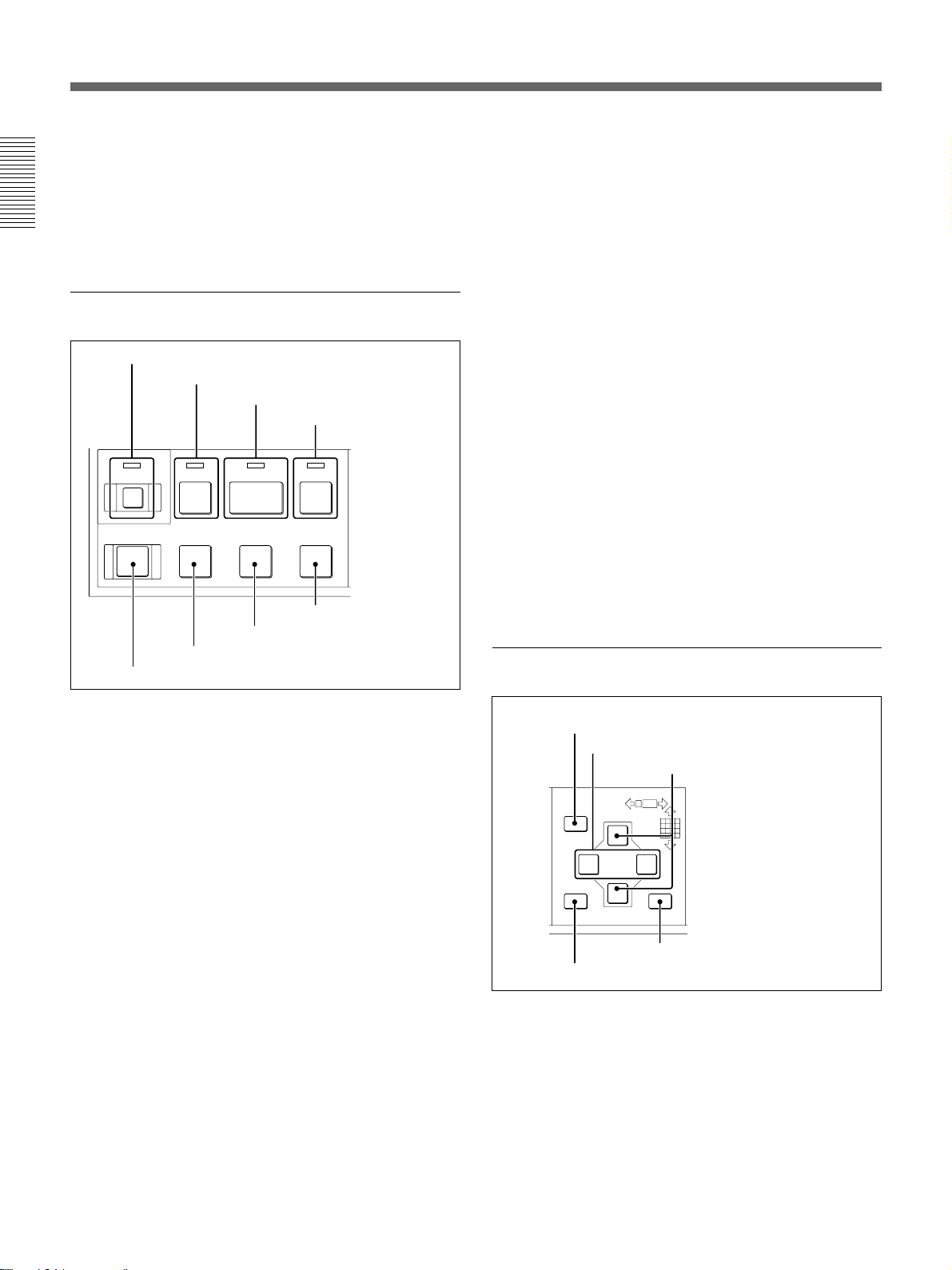
1 Tape transport control block
1 LOCK key and indicator
2 REW 0 key and indicator
3 PLAY ( key and indicator
4 F FWD ) key and
indicator
LOCK
7 STOP p key
6 FRAME ' key
5 REC r key
F FWDPLAYREW
‚·º
FRAME STOPFRAMEREC
¶π®æ
8 FRAME 7 key
4 F FWD ) (fast forward) key and indicator
Press this key to fast-forward the tape. The LED
indicator (green) lights.
This key functions as the forward search key during
playback.
5 REC r (record) key
Press this key to start recording.
6 FRAME ' key
Press this key to reverse the picture by one frame.
7 STOP p key
When you press this key during playback, playback
ends. When you press this key during recording, a
message to confirm that you want recording to stop is
displayed.
With the HSR-2/2P, guidance for the next operation is
displayed when you press this key in Playback During
Recording mode.
8 FRAME 7 key
Press this key to advance the picture by one frame.
2 Menu operation block
1 LOCK key and indicator
Press this key to turn on/off the key-lock function
(provided to prevent misoperation).
The LED indicator (red) lights when the function is on.
When this indicator is lit, other keys are disabled. To
release the lock, press the LOCK key again.
A four-digit password to release the lock can be
specified by using the Function Control menu.
For details, see “Setting Passwords” on page 5-16.
2 REW 0 (rewind) key and indicator
Press this key to rewind the tape. The LED indicator
(green) lights.
This key functions as the reverse search key during
playback.
3 PLAY ( key and indicator
Press this key to start playback. The LED indicator
(green) lights.
On the HSR-2/2P, this key also functions as the PRE
REVERSE PLAY key. When this key is pressed
during recording, playback is performed without
stopping recording.
For details, see “Playback During Recording” on page 2-12.
1 MENU key
2 CURSOR B/b keys
3 CURSOR V/v keys
5 RESET/NO key
4 SET/YES key
1 MENU key
Press this key to enter Menu mode. Press again to exit
the mode.
2 CURSOR B/b keys
Used to move from one layer to another in Menu
mode.
While monitoring a picture, you can switch pages
(different camera configuration with the same screen
divisions) with these keys.
1-6 Chapter 1 Overview
Page 12
3 CURSOR V/v keys
Used to move within a single layer in Menu mode.
While monitoring a picture, you can switch screen
division configurations with these keys.
4 SET/YES key
Press this key to register your menu settings.
This key also functions as the YES answer key for
YES/NO questions.
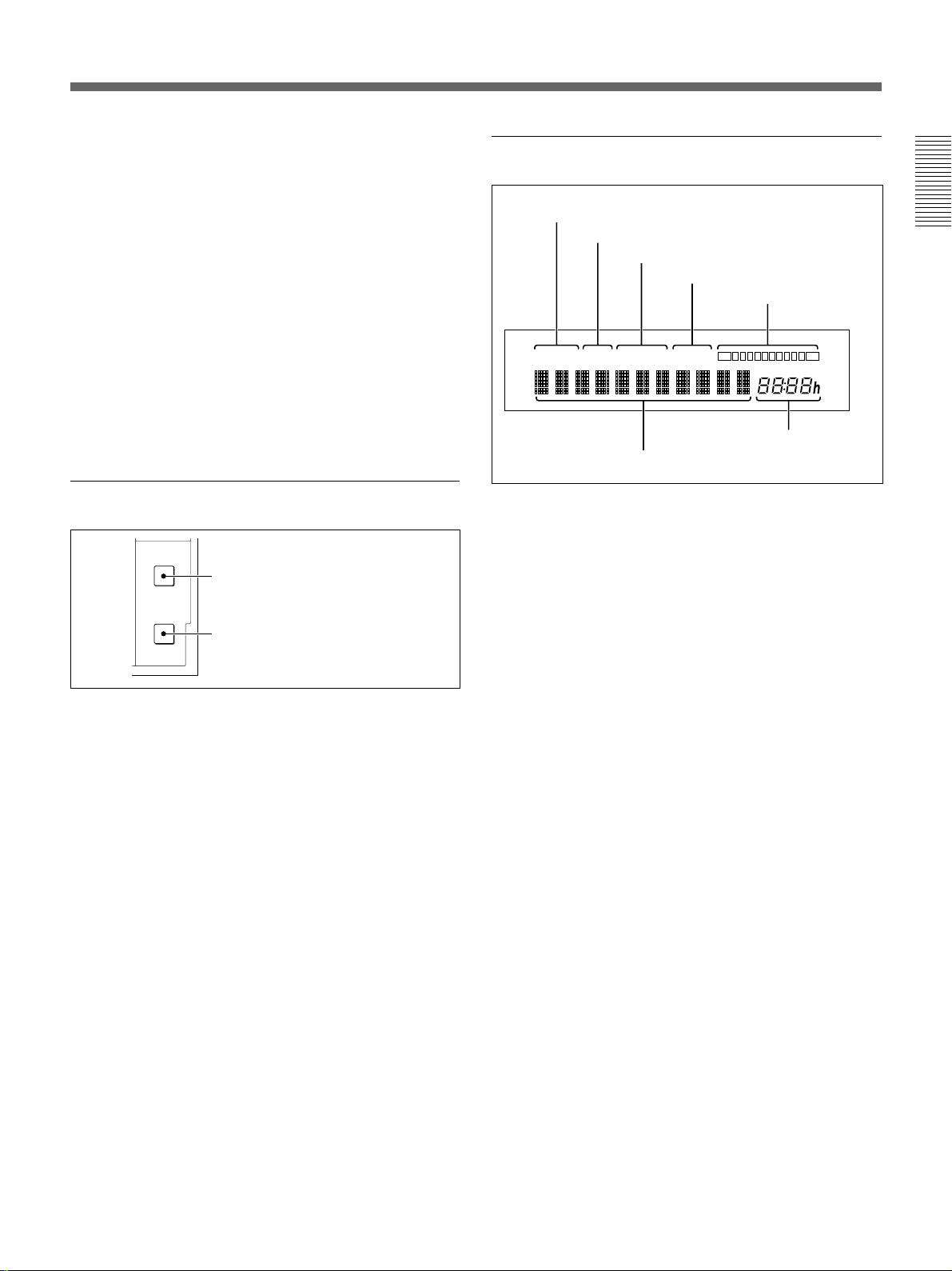
4 Indication window
1 ALARM indication
2 CONT indication
3 REPEAT indication
Chapter 1 Overview
4 TIMER indication
5 Tape remaining
indication
5 RESET/NO key
In normal operation mode, press this key to reset the
tape counter value in the indication window.
In menu mode, this key functions as the NO answer
key for YES/NO questions.
3 Search operation block
TIME
SEARCH
1 TIME SEARCH key
ALARM
SEARCH
2 ALARM SEARCH key
1 TIME SEARCH key
Press this key to locate a picture from a specific date
and time (Time Search). You can also locate the
recording end on a tape with this key (Rec End
Search).
For details, see “Time Search” on page 2-10 and “Rec End
Search” on page 3-14.
ALARM CONT REPEAT TIMER
6 Character display
S
E
TIME MODE
7 Time data
indication
1 ALARM indication
Lights when alarm recording is on.
For details, see “Alarm Recording” on page 3-4.
2 CONT (continuous) indication
Lights when continuous recording is set to ON on the
HSR-1/1P. It stays lit on the HSR-2/2P.
For details, see “Changing the Cassette During Recording”
on page 3-15.
3 REPEAT indication
Lights during repeat recording.
For details, see “Repeat Recording” on page 3-7.
4 TIMER indication
Lights when the timer recording is on.
For details, see “Timer Recording” on page 3-1.
2 ALARM SEARCH key
To display the list of alarm recordings on a tape and
transport the tape to the point of the specified
recording.
For details, see “Alarm Search” on page 3-9.
5 Tape remaining indication
Lights when a cassette is loaded, showing the
recording capacity remaining on the tape.
The remaining segment(s) will flash when the
remaining recording capacity becomes less than 3
minutes based on the calculation from the Tape Length
setting.
For the Tape Length setting, see “Setting the Recording
Modes” on page 5-12.
Chapter 1 Overview 1-7
Page 13

Locations and Functions of Parts
6 Character display
Shows character data, such as the tape counter value
and menu items.
The tape counter value is a relative time (hours,
minutes, seconds), which has the following meaning
Chapter 1 Overview
according to the mode of this recorder:
In playback mode: The tape position where the
video information being output has been recorded.
In recording mode: The tape position where the
current video information is recorded.
In other modes: The current tape position
Note
As the recorder employs a hybrid configuration of
HDD and tape, the counter value being displayed in
playback may considerably differ from the actual tape
position. Therefore, the tape counter value may jump
when you change the operation from PLAY to F.FWD/
REW mode.
7 Time data indication
Shows the time to record on a single tape (Time mode)
in hour units.
By setting “Front Time Disp” on the Indication
Control menu (page 4-8), the tape remaining time for
recording or current time can also be displayed in this
section.
1-8 Chapter 1 Overview
Page 14

Rear Panel
1 VIDEO IN connectors and 75-ohm termination switches
2 VIDEO OUT connectors
VIDEO IN VIDEO OUT
S VIDEO
1
5
9
13
A
2
6
10
14
B
3
7
11
15
4
8
12
16
ONOFF
ONOFF
75Ω
ONOFF
75Ω
75Ω
75Ω
PARALLEL I/O RS-232C
ONOFF
4 PARALLEL I/O connector
1 VIDEO IN (video input) connectors (BNC type)
and 75-ohm termination switches
For connecting video cameras.
Connectors 1 to 4 are provided as the standard inputs.
Connectors 5 to 16 can be added, four additionally
connectors for each optional HSRA-11 input board
mounted.
The termination switches are normally used in the ON
position.
For mounting an input board, see the instruction manual for
the HSRA-11.
2 VIDEO OUT (video output) connectors
S VIDEO (luminance/chroma signal output)
connector (4-pin): Outputs Y/C-separated S video
signals. Connect via a cable to the S video input of
a video monitor.
A (A image output) connector (BNC type): Outputs
composite video signals for monitoring. Character
signals are superimposed on the output signal
depending on the settings made on the Indication
Control menu (page 4-8).
B (B image output) connector (BNC type): Outputs
composite video signals. The signal to be output is
normally the same as that from the A connector.
The Image Control menu (page 4-6) permits you to
specify use of this output exclusively for a specific
camera. Note that the character signal is not
superimposed with such usage.
Chapter 1 Overview
3 POWER switch
POWER OFF ON
⁄AC IN
6 AC IN connector
5 RS-232C connector
3 POWER switch
For turning on/off the power to the recorder.
4 PARALLEL I/O connector (37-pin)
Used to input/output various control signals or to
supply control voltages.
You can use 24 pins for inputs and 8 pins for outputs.
The functions of these pins can be assigned from the
Remote Control menu (page 4-13).
5 RS-232C connector (9-pin)
Connect an editor or computer, via an RS-232C cable.
6 AC IN connector
Connect an AC power source via the supplied AC
power cord.
Chapter 1 Overview 1-9
Page 15

Locations and Functions of Parts
Screen Displays
Chapter 1 Overview
1 Recording modes
2 Time mode
3 Recording cycle
4 Image quality mode
5 Camera name
REC1 NORMAL 12 31 1999 FRI 11:59:59 AM
xxxxH xx.xS SUPER ALARM ERRORxx-xxx HDD
1 XXXXXXXXXX NOT ORIGINAL
1 Recording modes
When recording or monitoring, the currently selected
mode and recording mode number (REC1 to REC5)
are displayed.
NORMAL: Normal recording
TIMER: Timer recording
ALARM: Alarm recording in Normal mode
INT-A: Alarm recording in Interleave mode
PRE-A: Alarm recording in Prealarm mode
EVT-A: Alarm recording in Event mode
FRM-A: Alarm recording in Frame mode
These items are not displayed during playback.
Whether to display them can be set on the Indication
Control menu.
6 Date/time
7 HDD indication
8 Status indication
9 ALARM indication (upper)
ALARM
0 ALARM indication (lower)
!¡ NOT ORIGINAL indication
4 Image quality mode
When recording or monitoring, the currently selected
Image quality mode is displayed.
During playback, that used for recording is displayed.
Whether to display them can be set on the Indication
Control menu.
5 Camera name
When recording or monitoring, the name specified for
the current camera is displayed.
During playback, the camera name recorded on the
tape is displayed.
The names of the cameras and whether to display them
can be set on the Indication Control menu.
2 Time mode
When recording or monitoring, the currently selected
Time mode is displayed.
Whether to display it can be set on the Indication
Control menu.
3 Recording cycle
When recording or monitoring, the currently selected
Recording cycle is displayed.
During playback, that used for recording is displayed.
Whether to display it can be set on the Indication
Control menu.
1-10 Chapter 1 Overview
6 Date/time
When recording or monitoring, the current date and
time are displayed.
During playback, the date and time when the picture
was recorded are displayed.
Whether to display them and the display format can be
set on the Indication Control menu.
For the Indication Control Menu, see Chapter 4 “Menu
Operations.”
7 HDD indication
If no tape is loaded in the recorder when some
information that has not been recorded on a tape
remains on the HDD, an “HDD” indication flashes.
For details, see “HDD Recording/Playback” on page 3-11.
Page 16

8 STATUS indication
The current operating mode (REC, PLAY, F FWD,
REW, etc.) is displayed.
9 ALARM indication (upper)
If there is either an alarm input common to all cameras
or an alarm input from a certain camera to the parallel
input, the indication “ALARM” is superimposed on
the upper portion of the screen, regardless of the
screen display currently selected. This indication also
appears even during playback if any new alarm input
to the recorder is generated.
0 ALARM indication (lower)
If there is an external alarm input, the indication
“ALARM” is superimposed on the lower portion of
the screen. As this information is recorded on the tape,
the indication is also obtained in playback.
!¡ NOT ORIGINAL indication
Thanks to the original watermark system, a “NOT
ORIGINAL” indication is superimposed, if the image
being played may have been artificially altered.
This indication can be seen only in Still mode (either
FRAME key pressed) with the full-screen display.
Note
This indication is disabled in alarm recording in
FRAME mode, in Playback During Recording (HSR2/2P) mode, or when you switch the unit from highspeed playback to variable playback.
Chapter 1 Overview
Chapter 1 Overview 1-11
Page 17

Basic Operations
Handling Cassettes
Usable Cassettes
The following standard- and mini-sized cassettes of DV-format can be
used with this recorder.
Chapter 2
Chapter 2 Basic Operations
Notes on usage
Model name Size
DV- and PDV-series, such as DV-270RM and PDV-184N Standard
DVM- and PDVM-series, such as DVM-30MM and PDVM-40N Mini
The number included in the name of a DV- or DVM-series model indicates the
tape length (unit: minute). (Ex.: 270 minutes with DV-270RM).
In case of a PDV- or PDVM-series model, the value obtained by multiplying the
number included in the name by 1.5 corresponds the tape length (unit: minute).
(Ex.: 276 minutes with PDV-184N).
• When a cassette is to be stored for a long time, rewind the tape to the
beginning, mount it in the original case, and place it vertically. Leaving a
cassette lying flat may cause noisy pictures.
• If any undue force is applied to the cassette, such as by dropping it, the
tape may become slackened, causing abnormal recording/playback.
Before using a cassette, be sure to check that the tape is not slacked.
To check the tape slack
Gently turn the reel in the direction
of the arrow using a paper clip or
equivalent. If there is no slack, the
reel will not rotate. Then, insert the
cassette in the recorder and remove
it after about 10 seconds.
Paper clip, or
equivalent
Reel
Chapter 2 Basic Operations 2-1
Page 18
Handling Cassettes
REC
SAVE
S
REC
EJECT
‚
§
·º
¶π® æ
†
Chapter 2 Basic Operations
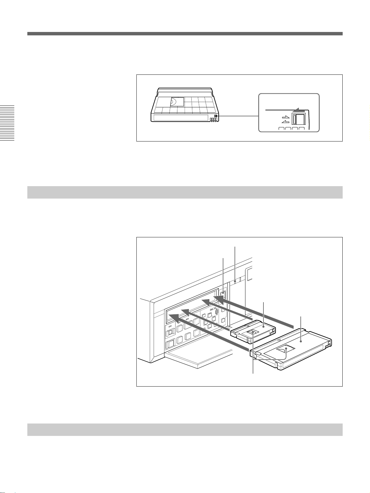
Inserting a Cassette
To prevent unintentional erasure
Set the REC/SAVE switch to the SAVE position.
REC/SAVE switch
Set to SAVE.
To rerecord on a cassette
Return the REC/SAVE switch to the REC position. No recording will be
made on a cassette with the switch set to SAVE.
Insert/eject a cassette with the power on.
Open the front panel cover and insert the cassette through the opening as
shown below.
Cassette indicator
EJECT button
Mini-sized cassette (Align it with
the concave portion at the center
of the opening.)
Standard-sized cassette
With the tape window facing upward
Ejecting a Cassette
2-2 Chapter 2 Basic Operations
The cassette is automatically pulled into the operating position and the
cassette indicator lights up.
Press the EJECT button.
The cassette indicator flashes while the cassette is being ejected.
Page 19
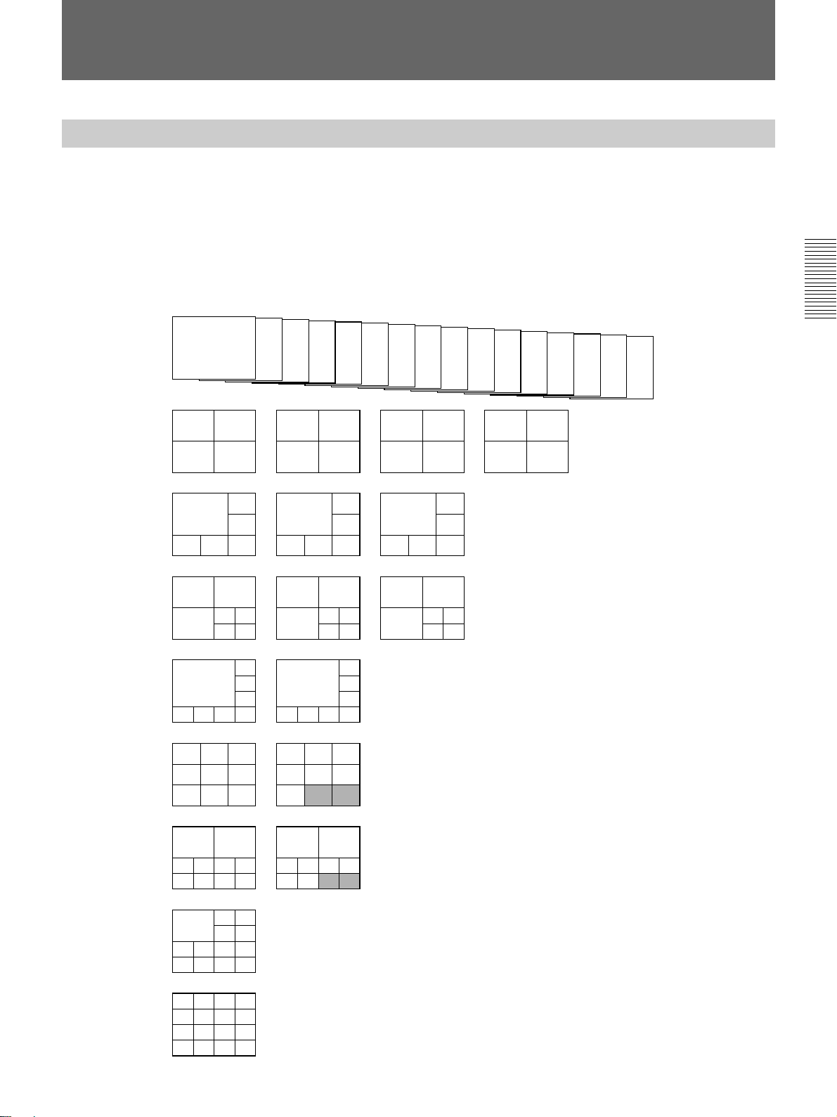
Monitoring Picture
Dividing the Screen
1
2
Full screen
(16 pages)
In addition to the capability to show the picture from a specified camera on
the full screen, this recorder has a multiplexer function to divide the screen
into multiple divisions and permit you to view the pictures from multiple
cameras at a glance.
In screen division modes, you can select the respective number of pages
(the same divisions with different camera configurations) for monitoring.
The following camera numbers have been assigned at the factory.
3
4
5
6
7
8
9
10
11
12
13
14
15
16
Chapter 2 Basic Operations
4 divisions
(4 pages)
6 divisions
(3 pages)
7 divisions
(3 pages)
8 divisions
(2 pages)
9 divisions
(2 pages)
10 divisions
(2 pages)
13 divisions
(1 page)
16 divisions
(1 page)
12
34
Page 1 Page 2 Page 3 Page 4
2
1
3
456
Page 1 Page 2 Page 3
1
3
5678
123
456
789
2
45
67
Page 1 Page 2 Page 3
2
13
4
Page 1 Page 2
Page 1 Page 2
56
78
7
1
8
91011
1
2
89
3
10 11
9
110
11
12 13 14 15
10 11 12
13 14 15
16
910
11 12
12
1
13
14 15 16
1
2
12 13
3
14 15
Camera assignments
You can assign the connected cameras to any division
by using Moni Display Structure of the Image Control
menu.
For the assigning method, see “Setting the Display
Structures” on page 5-9.
Border lines
You can select whether the lines are to be displayed,
12
3456
78910
Page 1 Page 2
23
1
45
6789
10 11 12 13
1234
5678
9 101112
13 14 15 16
12
11 12 13 14
15 16
and if so, in black or in white on the Indication Control
menu.
Superimposing
According to settings made on the Indication Control
menu, various information, such as the camera
number/name, date/time, etc. can be superimposed
onto the signal input from a camera.
The type of superimposed characters can also be set.
See Chapter 4 “Menu Operation” for the Indication Control
menu and “Setting Camera Names” on page 5-8 for camera
names.
13 14
15 16
Chapter 2 Basic Operations 2-3
Page 20

Monitoring Picture
Switching the Pictures
The number keys of the cameras whose pictures can be monitored flash in
green.
To select the picture(s) for monitoring, use the flashing camera number
keys or the CURSOR V/v/B/b keys.
Chapter 2 Basic Operations
To select a specific camera
To select a divided screen
S
EJECT
◊
ı ∫
CURSOR
√
RESET/NO
SEARCH
ALARM
SEARCH
TIME
MENU
LOCK
F FWDPLAYREW
‚§·º
FRAME STOPFRAMEREC
SET/YES
¶π® æ
REC
†
DIGITAL SURVELLANCE RECORDER HSR-1
1234
5678
9
10 11 12
13 14 15 16
DIGITAL
TIMELAPSE
CONTROL-S
CURSOR V/v/B/b keys Camera number keys
For connections and Image Control menu operation, see Chapter 5 “Connections
and Preparations.”
Press the number key corresponding to the camera to be monitored.
The key then flashes in amber, and the picture of the selected camera is
displayed on the full screen.
Press the same key again to return to the pervious condition.
To automatically switch pages
2-4 Chapter 2 Basic Operations
Multiple camera pictures can be monitored by selecting the screen division
mode.
To change the structure
Press the V or v key.
Each time you press either of the keys, the display switches to the next of
night patterns, from the full screen to 16-division mode.
To change the pages
Press the B or b key.
The pages are cyclically switched.
The pages of the structure selected using the V or v key are automatically
switched at the cycle specified in the range of 1 to 60 seconds.
Set MONITOR to AUTO on the Image Control menu.
For the settings, see Chapter 5 “Connections and Preparations.”
Page 21

Recording
Normal Recording
About the recording modes
Up to five user-preset recording modes can be registered to this recorder.
You may specify a set of recording requirements to each recording mode.
Once the recording modes are set, the specified requirements for recording
are set merely by selecting one of your preset recording modes.
Example of setting a user-preset recording mode:
CAMERA NUMBER : 8
TAPE LENGTH: 270MIN
IMAGE QUALITY: SUPER
TIME MODE: 33H
REC CYCLE: 1.00SEC
When recording is executed with the example recording mode selected,
pictures from all eight cameras that have been specified to be used for
recording (set to REC) are cyclically recorded once per 1.00 second in
SUPER image quality mode (HSR-1/2: horizontal 720 × vertical 240,
HSR-1P/2P: horizontal 720 × vertical 288 pixels) for 33 hours on a single
cassette of 270-minute tape length.
Recording modes can be registered by using “Setting of Rec Mode” of the
Recording Function menu.
For registrating the recording modes, see Chapter 5.
Chapter 2 Basic Operations
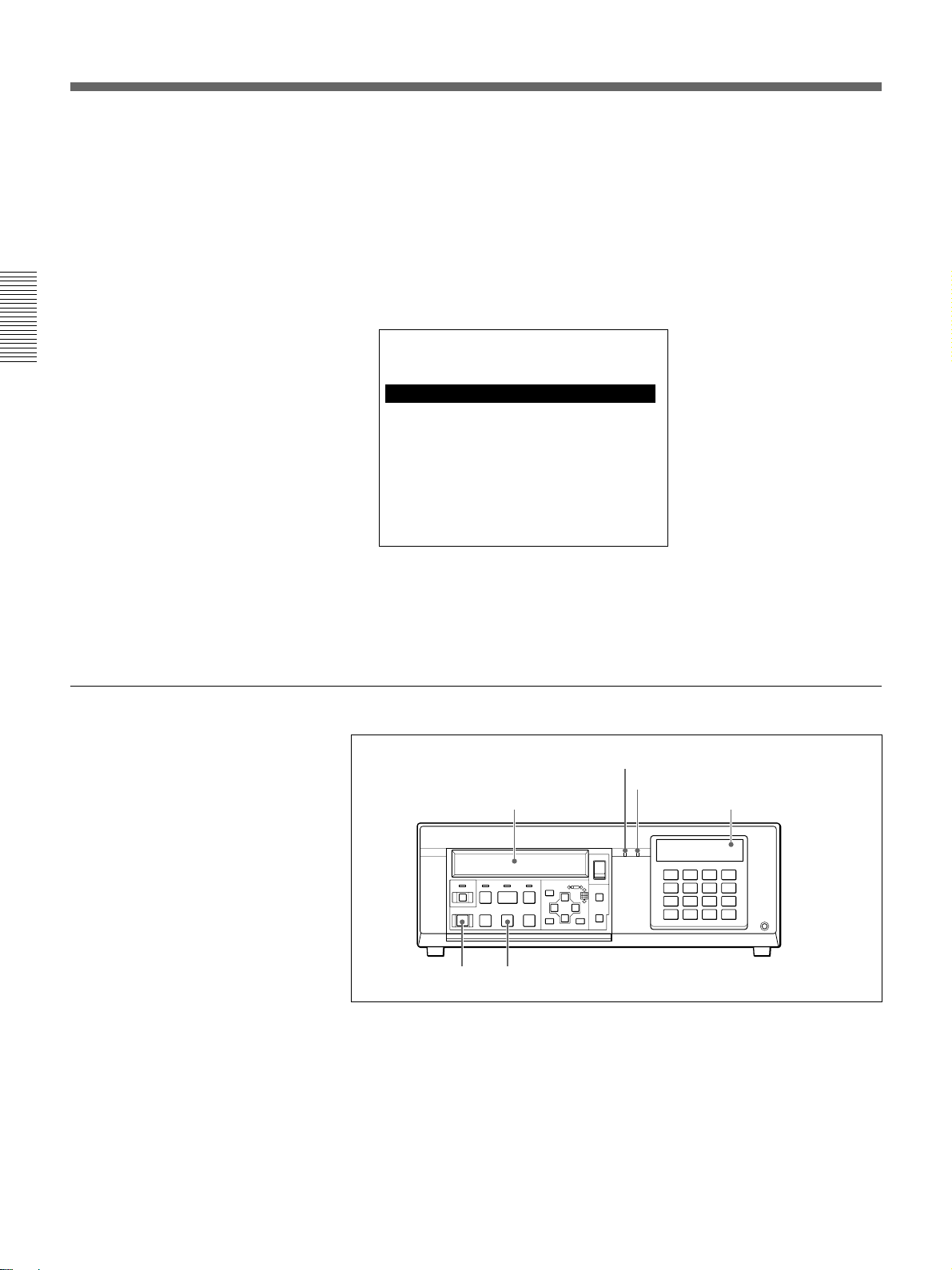
To select a recording mode
A recording mode for normal recording can be selected on the monitor
screen or on the character display on the front panel.
Once you select a mode, it is not necessary to select the mode again unless
it needs to be changed.
See Chapter 4 “Menu Operations” for additional information on the operation.
1 Enter Menu mode by pressing the MENU key.
2 Highlight REC FUNCTION MENU (or display “RecFuncMenu” on
the front panel) of the Top menu (page 4-5) by pressing the V or v key,
then press the b key.
The Recording Function menu is displayed.
SETUP MENU
REC FUNCTION MENU
NORMAL REC : MODE 1
TIMER REC
ALARM REC
REPEAT REC : OFF
CONTINUOUS REC1): OFF
SETTING OF REC MODE
1) HSR-1/1P only
Chapter 2 Basic Operations 2-5
Page 22
Recording
Chapter 2 Basic Operations
The Recording Function menu item that had been selected when you
left the menu the last time is displayed in the character display on the
front panel.
3 Highlight NORMAL REC (or display “RecMode”) by pressing the V
or v key, then press the b key.
The menu switches to the recording mode selection layer for normal
recording.
SETUP MENU
REC FUNCTION MENU
NORMAL REC : MODE 1
M
REC MODE 1
*
REC MODE 2
REC MODE 3
REC MODE 4
REC MODE 5
To execute recording
4 Highlight the desired recording mode, REC MODE 1 to 5 (or display
Mode 1 to 5) by pressing the V or v key, then press the SET key.
A message “NOW SAVING” is displayed, and the selection is
registered.
Cassette indicator
REC indicator
Tape remaining indication
DIGITAL SURVELLANCE RECORDER HSR-1
1234
5678
9
10 11 12
13 14 15 16
DIGITAL
TIMELAPSE
CONTROL-S
S
LOCK
2
1
F FWDPLAYREW
‚§·º
FRAME STOPFRAMEREC
¶π® æ
STOP key
MENU
SET/YES
◊
ı ∫
CURSOR
√
RESET/NO
SEARCH
SEARCH
EJECT
ALARM
REC
†
TIME
1 Insert a cassette.
The cassette indicator and the tape remaining indication light.
2-6 Chapter 2 Basic Operations
2 Press the REC key.
The REC indicator lights, and recording starts in the selected recording
mode.
When the remaining tape capacity becomes less than 3 minutes during
recording, the tape remaining indication flashes and a beep sounds. The
beep will stop when you press any key.
Page 23

To stop recording before the end of a tape
1 Press the STOP key.
A message to confirm that you want recording to stop is displayed.
2 Press the YES key.
Notes
• When you press the YES key, the unit starts copying the data remaining
on the hard disk to the cassette tape. This operation may take 90 seconds
at maximum, and you cannot change modes until it is completed. During
this operation, the remaining time until a mode shift is enabled is
displayed on the monitor screen and the character display of the recorder.
(With the HSR-2/2P, it may take more than 90 seconds if you stop
recording immediately after ending a Playback During Recording
operation.)
• Some images recorded on the beginning of a tape may not be played.
The duration that cannot be played depends on the recording cycle, the
number of cameras, and the image-quality mode.
Example With a 1-second recording cycle, eight cameras, HIGH mode:
approx. 3 seconds
With alarm recording in FRAME mode: approx. 6 frames
• If very few picture frames have been recorded continuously, time search
and alarm search may fail, or the pictures may not be played correctly. It
is therefore recommended to perform recording for a certain duration
continuously. The recording duration required for correct playback
depends on the recording cycle, the number of cameras, and the image
quality mode.
Example With a 1-second recording cycle, eight cameras, HIGH mode:
approx. 10 seconds or more
As continuously recorded duration is short in EVENT- or PREALARM-mode alarm recording, it is especially recommended to specify as a short
recording cycle as possible.
Chapter 2 Basic Operations
Data recording
The HSR-1/1P/2/2P records the following information as data along with
the video signals.
The recorded data can be superimposed on the playback picture by so
specifying on the Indication Control menu (page 4-8).
Camera names
The names specified for the cameras used for recording (up to 12
characters each) are recorded.
The default names are “1 CAMERA” to “16 CAMERA,” which can be
changed from the Indication Control menu.
For details, see “Setting Camera Names” on page 5-8.
Recording mode/Time mode/Recording cycle/Image quality
mode
Recording mode, Time mode, Recording cycle, and Image quality mode
used for recording are recorded.
Chapter 2 Basic Operations 2-7
Page 24

Recording
Chapter 2 Basic Operations
Date/Time
The date and time of recording are recorded.
The camera number, date and time of recording can also be recorded as
image on the tape. The data recorded as image are always be
superimposed on the playback picture.
Whether to record the data as image is set on the Indication Control menu
(page 4-8), which is set at the factory to record.
The superimposing position of the date and time can also be set on the
Indication Control menu.
2-8 Chapter 2 Basic Operations
Page 25

Playback
Normal Playback
The tape recorded on this recorder is played back in accordance with the
mode set for recording.
12
S
†
EJECT
◊
ı ∫
CURSOR
√
RESET/NO
SEARCH
ALARM
SEARCH
TIME
MENU
LOCK
F FWDPLAYREW
‚§·º
FRAME STOPFRAMEREC
SET/YES
¶π® æ
DIGITAL SURVELLANCE RECORDER HSR-1
REC
1234
5678
9
13 14 15 16
10 11 12
DIGITAL
TIMELAPSE
CONTROL-S
Chapter 2 Basic Operations
REW key
F FWD key
FRAME 7 keyFRAME ' key
STOP key
1 Insert the recorded cassette.
2 Press the PLAY key.
Playback begins.
The date/time, if recorded as image, are superimposed on the playback
picture.
Whether to superimpose the name of the camera, recording mode, time
mode, recording cycle, and image quality mode used in recording and the
date/time recorded as data can be set on the Indication Control menu (page
4-8).
To advance the picture at a high speed
Press and hold the F FWD key.
Normal playback is resumed when you release the key.
To reverse the picture at a high speed
Press and hold the REW key.
Normal playback is resumed when you release the key.
To advance the picture by one frame
Press the FRAME 7 key.
The picture freezes at the next frame.
To resume normal playback, press the PLAY key.
To reverse the picture by one frame
Press the FRAME ' key.
The picture freezes at the previous frame.
To resume normal playback, press the PLAY key.
To stop playback
Press the STOP key.
Chapter 2 Basic Operations 2-9
Page 26

Playback
Chapter 2 Basic Operations
Dividing structure of the playback screen
Search speed
The maximum search speed depends on Recording mode which was
specified for recording.
The fewer cameras for recording, the longer the recording cycle, and the
lower the image quality mode, the higher the speed at which you can
monitor the playback picture.
Note
If you try to search before the tape top or after the tape end, a message “No
playback data” is displayed. The same message appears also if you try to
search before the recording starting point or after the ending point on the
hard disk.
In the same manner as when monitoring, the screen can be divided into 16
divisions at maximum, and you can assign a camera to each division as
desired.
The camera assignment for playback can be made independent from that
for monitoring.
See “Monitoring Picture” (page 2-3) for the screen dividing structures, and
Chapter 5 “Connections and Prepartions” for the camera assignment.
Time Search
Monitoring the playback picture and the current camera inputs
simultaneously
You can assign live camera inputs to some divisions of the playback
screen.
You can view the current picture of the assigned camera in addittion to the
playback pictures.
Using the date/time data recorded on a tape, you can locate the picture for
any specified date and time.
13
S
EJECT
◊
ı ∫
CURSOR
√
RESET/NO
SEARCH
ALARM
SEARCH
TIME
MENU
LOCK
F FWDPLAYREW
‚§·º
FRAME STOPFRAMEREC
SET/YES
¶π® æ
REC
†
DIGITAL SURVELLANCE RECORDER HSR-1
1234
5678
9
10
DIGITAL
TIMELAPSE
CONTROL-S
2-10 Chapter 2 Basic Operations
42
1 Insert the recorded cassette.
Page 27

2 Press the TIME SEARCH key.
Search Destination Setting mode is activated.
TIME SEARCH
8 15 1998 3:05: 18 PM
REC END SEARCH
SHIFT : Mm
CHANGE: µ
INPUT : NUM KEY
SEARCH : SET KEY
ABORT: TIME SEARCH KEY
For REC END SEARCH, see “Rec End Search” on page 3-14.
3 Shifting the input position using the b key, set the date and time.
The date (year/month/day) and time (hour/minute/second) can be set
by either changing the value in turn using the V or v key or by direcly
entering the value using the numeric keys.
Press the V or v key to switch between AM and PM.
Chapter 2 Basic Operations
4 Press the SET key.
The tape rewinds or fast-forwards, searching for the tape position of the
specified date/time.
When the search is completed, the picture of that position is displayed in
still mode.
To cancel the time search
• While entering the date/time, press the TIME SEARCH key again.
• While the tape is running, press the STOP key.
Chapter 2 Basic Operations 2-11
Page 28

Playback During Recording (HSR-2/2P only)
Chapter 2 Basic Operations
With the HSR-2/2P, you can play the latest recorded scene or a scene
recorded before without stopping recording now in progress. You can also
play a scene recorded on other cassettes. Fast-forward, rewind, time
search and alarm search operations are also possible during recording.
In playback during recording, pictures are recorded and stored on the hard
disk, and will be copied to the tape when Playback During Recording
mode is canceled.
Keys that can be used in Playback During Recording mode,
and their functions
When one of the keys below is pressed during recording (the REC
indicator is lit), Playback During Recording mode is activated, and the
operation using these keys is performed while recording is continued using
the hard disk.
PLAY (PRE REVERSE PLAY) key: To locate the preset point of the
pre-reverse time on the hard disk, before the current time. Playback
starts from that point. The pre-reverse time can be set on the PRE
REVERSE TIME SET display from the Function Control menu. Prereverse playback is always directly from data on the hard disk. If
recording has not yet been made for the duration of the pre-reverse
time, playback starts from the recording starting point. This key
functions as the normal playback start key after a cassette operation.
TIME SEARCH and ALARM SEARCH keys: To execute a Time
search, Rec-end search or Alarm search operation.
EJECT key: To change the cassette.
F FWD and REW keys: To fast-forward or rewind a tape.
STOP key: To stop playback during recording. A guidance for the next
operation is displayed.
Note
Even when the REC indicator is lit, the unit will not be switched to
Playback During Recording mode by pressing the REW key at the tape
top.
If the optional SVRM-100A remote control unit is connected, you can
operate the HSR-2/2P using the keys on the SVRM-100A. The Jog/Shuttle
operation from the SVRM-100A is also possible.
Requirements for Playback During Recording
Recording cycle
In order to play back without stopping recording, the recording cycle must
be of a certain value or larger. The valid minimum value for the recording
cycle is displayed under the current REC CYCLE value on the setting
display for a Recording mode.
Even if the current set value is smaller than the valid minimum value, the
Playback During Recording operation will be enabled by setting
PRIORITY of the Function Control Menu to PLAY. In this case, the
recording cycle will be increased automatically to the same value as the
valid minimum value when Playback During Recording mode is activated.
(The recording cycle will return to the original value when Playback
During Recording mode is canceled.)
2-12 Chapter 2 Basic Operations
Page 29

If the set value is smaller than the valid minimum value and REC is
selected for PRIORITY, a Playback During Recording operation cannot be
performed.
For details on the setting of the recording cycle, see “Setting the Recording
Modes” on page 5-12, and for the setting of PRIORITY, see “Function Control
Menu” on page 4-11.
Other requirements
• A Playback During Recording operation cannot be performed just after
recording has started. Activate Playback During Recording mode after
continuing recording for a certain period. For example, it is about 15
seconds with settings of 4 camera inputs, 0.4-second recording cycle, and
SUPER image quality.
• The message “NOT ORIGINAL” is not displayed during a Playback
During Recording operation.
• During a Playback During Recording operation, the camera name that
you have preset by menu operation is displayed. Therefore, the correct
camera name may not be displayed if a tape which is recorded in another
place is played back.
• The user data cannot be played back during a Playback During Recording
operation (when the RS-232C is used).
Chapter 2 Basic Operations
To play back the latest recorded scenes (Pre-reverse Playback)
1 Start recording as described in “Recording.”
2 Press the PLAY (PRE REVERSE PLAY) key.
Playback During Recording mode is activated. The point on the hard disc
just before the time set for PRE REVERSE TIME in the Function Control
Menu (1 to 99 minutes) is located, and playback starts. Recording is
continued using the recording buffer of the HDD.
For details on setting the pre-reverse time, see “Setting the Pre-Reverse Time” on
page 5-17.
Status display during a Playback During Recording operation
When Playback During Recording mode is activated, the display
“REC&PLAY**%” appears on the screen (“**” indicates the percentage
of remaining disk capacity available for recording).
As recording is made only on the hard disk in Playback During Recording,
the REC indicator on the front panel rapidly flashes.
Note
When a recording is made up to the maximum recording capacity of the
hard disk (“0%” is displayed) in Playback During Recording mode, data
are overwritten from the oldest. If the remaining disk capacity falls to 5%,
a beep will sound, and a caution message will be displayed.
The caution message will disappear when you press any key. In order to
avoid overwriting before the data on the hard disk are copied to a tape,
cancel Playback During Recording mode before the remaining capacity
falls to 0%.
(Continued)
Chapter 2 Basic Operations 2-13
Page 30

Playback During Recording (HSR-2/2P only)
After checking the recorded picture with a Playback During Recording
operation, be sure to cancel Playback During Recording mode. If you
leave Playback During Recording mode activate for a long time after this
operation, the recording capacity of the hard disk drive may be exhausted,
and the recorded data on the hard disk may be erased before it is copied to
a tape.
To start playback from a desired tape position
Press the F FWD or REW key and find the position where you want to
Chapter 2 Basic Operations
To search for a picture
start playback.
Playback starts once you press the PLAY key. (In this case, playback
starts from the position where you press the PLAY key, regardless of your
preset pre-reverse time.)
To play back another cassette
Press the ALARM SEARCH or TIME SEARCH key. Recording
continues, and you can execute Alarm Search or Time Search.
For details on the search operations, see “Alarm Search” (page 3-9) or “Time
Search” (page 2-10).
You can also perform a search operation using the F FWD and REW keys
or frame-to-frame using the FRAME keys in the same way as in the
ordinary playback mode. A search operation can also be performed using
the Jog/Shuttle dial of the SVRM-100A.
1 With recording continued, press the EJECT key.
Playback During Recording mode is activated, and the cassette is
ejected. Recording continues using the hard disk.
2 Insert a cassette to be played and press the PLAY key.
Playback of the inserted cassette begins.
To cancel the Playback During Recording mode
After checking the recorded pictures with a Playback During Recording
operation, cancel Playback During Recording mode and copy the data on
the hard disk to the tape.
1 Press the STOP key.
Guidance for the next operation is displayed.
2-14 Chapter 2 Basic Operations
Page 31

2 Press the REC key.
Playback During Recording mode is canceled, and the unit is set to the
ordinary recording mode.
The data recorded on the hard disk during Playback During Recording
operation are copied to the tape.
About the continuity of recording on a tape
The present tape position may be different from the tape position when
you started a Playback During Recording operation because of changing
cassettes or tape running in Playback During Recording mode. In such a
case, a message to show that the tape position has been moved is displayed
when you press the REC key in step 2 of “To cancel Playback During
Recording mode.”
To continue recording from the present tape position
Press the YES key.
Playback During Recording mode is canceled, and recording continues
from the present tape position.
To continue recording from the original tape position when you
have started a Playback During Recording operation
1 Press the NO key.
The display returns to the guidance in step 1 of “To cancel Playback
During Recording mode.”
Chapter 2 Basic Operations
2 Find the original tape position by using the Rec End Search function.
If the cassette has been changed, first insert the original cassette and
locate the original position.
3 Press the REC key again.
Playback During Recording mode is canceled, and copying of the data
from the hard disk to the tape begins, maintaining continuity on the
tape.
To stop recording
Press the STOP key.
A message to confirm that you want recording to stop is displayed.
Press the YES key.
A cassette cannot be ejected if copying from the hard disk to the tape has
not completed. It may take more than 90 seconds until the cassette can be
ejected after you press the YES key.
Chapter 2 Basic Operations 2-15
Page 32

Chapter 3
Convenient Recording/
Playback Functions
Timer Recording
You can set the recorder to start recording or change
recording modes at a specified time of day.
By changing recording modes, you can use different
cameras for recording in different time slots, or record
at a certain cycle in the daytime and record only when
an alarm signal is detected at night.
The time as well as the recording mode (1 to 5) must
be specified.
Chapter 3 Convenient Recording/Playback Functions
To set the timer
Timer setting is made on a special display on the
monitor screen.
Once you set the timer, it is not necessary to repeatedly
set it if it is not to be changed.
See Chapter 4 “Menu Operations” for additional
information.
1 Enter Menu mode by pressing the MENU key.
2 Highlight REC FUNCTION MENU of the top
menu (page 4-5) by pressing the V or v key, then
press the b key.
The Recording Function menu is displayed.
SETUP MENU
REC FUNCTION MENU
M NORMAL REC : MODE 1
m TIMER REC
ALARM REC
REPEAT REC : OFF
CONTINUOUS REC1): OFF
SETTING OF REC MODE
1) HSR-1/1P only
(Continued)
Chapter 3 Convenient Recording/Playback Functions 3-1
Page 33

Timer Recording
3 Highlight TIMER REC by pressing the V or v key,
then press the b key.
The menu shifts to the selection layer of timer
recording.
SETUP MENU
REC FUNCTION MENU
TIMER REC
M TIMER REC : OFF m
TIMER
4 Highlight TIMER SET by pressing the V or v key,
Chapter 3 Convenient Recording/Playback Functions
then press the b key.
The TIMER set display appears on the monitor
screen and the indication at the upper left flashes.
• By specifying another set of time and recording
mode in the right column, recording is continued
after changing the recording mode at the time
specified in the right column.
• If recording mode need not to be changed, delete
the time by pressing the RESET key. When the
time is deleted, “––––” is displayed.
• Time Mode is automatically calculated and
displayed according to the selected recording
mode.
• To stop recording at the specified time, set 0 in
the REC column.
• When you set “A” in the REC column, alarm
recording will start at the specified time. This
alarm recording is performed in the mode set on
the alarm set display (page 3-5).
7 Perform the same settings for each day of the week
when required.
For the day which recording is not necessary,
delete the day or time by pressing the RESET key.
TIMER set display
TIMER
DAY TIME REC TIME REC
Mo 0:00AM 1, 5:00PM 2
Tu 0:00AM 1, 5:00PM 2
We 0:00AM 1, 5:00PM 2
Th 0:00AM 1, 5:00PM 2
Fr 0:00AM 1, 5:00PM 0
Sa –: —— –, –: —— –
Su –: —— –, –: —— –
TIME MODE=1900HOURS
5 Set the day(s) by pressing the V or v key.
Mon-Fr: To operate at the same setting from
Monday to Friday.
Everyday: To operate at the same setting
everyday.
6 Set the time and the recording mode number by
pressing the V or v key in the sequence then move
to the next digit or item by pressing the b key.
• Pressing !¢ of the numeric keys selects the item
on the previous line, and pressing !∞ selects the
item on the next line.
8 When the settings are completed, press the SET
key.
A message “NOW SAVING” is displayed and the
settings are stored in nonvolatile memory.
Notes
•The time mode shown on the TIMER set display
suggests the timing for changing the cassette tape
next after starting recording at 0:00 AM on Monday.
That is, if “TIME MODE=178HOURS” is shown,
you may change the tape by 10:00 AM on the next
Monday.
However, recording is not always started at 0:00 AM
on Monday, so the time mode may not indicate the
precise time. The difference will be large especially
when the time mode value is small.
•If the calculated time mode exceeds 9999 hours,
“
” is displayed.
****
•When “A” is set in the REC column, “
displayed for TIME MODE, as the time mode cannot
be calculated.
•When ALARM REC is set to ON in NORMAL or
INTERLEAVE mode on the recording function menu
(page 3-6), alarm recording will be activated
regardless of the timer recording setting.
However, alarm recording in FRAME, EVENT or
PREALARM will be activated only when “0” or “A”
is set in the REC column for timer recording.
****
” is
3-2 Chapter 3 Convenient Recording/Playback Functions
Page 34

To activate timer recording
4
TIMER indication
To cancel timer recording
To stop recording in progress
Press the STOP key.
S
†
EJECT
◊
CURSOR
ı ∫
√
RESET/NO
SEARCH
ALARM
SEARCH
TIME
MENU
LOCK
F FWDPLAYREW
‚§·º
FRAME STOPFRAMEREC
SET/YES
¶π® æ
DIGITAL SURVELLANCE RECORDER HSR-1
REC
1234
5678
9
13 14 15 16
11 12
10
CONTROL-S
315
1 Highlight TIMER REC on the display shown in
step 3 on the previous page by pressing the V or v
key, then press the b key.
The menu shifts to timer recording selection.
SETUP MENU
REC FUNCTION MENU
TIMER REC
TIMER REC : OFF
M
OFF m
*
ON
DIGITAL
TIMELAPSE
To cancel timer recording
Return the TIMER REC setting to OFF on the display
in step 1.
If there is recording in progress, it will be continued.
Chapter 3 Convenient Recording/Playback Functions
2 Highlight ON by pressing the V or v key, then
press the b key.
3 Press the SET key to leave Menu mode.
4 Insert a cassette.
5 Press the REC key.
The TIMER indication of the indication window
lights, and the timer recording selected in step 2 will
be activated.
Chapter 3 Convenient Recording/Playback Functions 3-3
Page 35

Alarm Recording
You can set the recorder to start recording or change
the recording mode when an alarm signal is input to
the PARALLEL I/O connector at the rear panel.
For the alarm signals, you can specify a signal
common to all cameras or signals for specific cameras.
The signal assignments are made from the Remote Control
menu (page 4-13).
Alarm recording modes
The recorder provides five modes of Alarm recording.
For alarm recording, you may set the recording mode
for alarm recording and a condition for canceling
alarm recording.
The items to be set depend on the Alarm recording
modes.
Chapter 3 Convenient Recording/Playback Functions
NORMAL mode
When an alarm signal is input during recording, the
recording mode is changed.
You can set the recording mode for alarm recording
and Cancel condition.
Alarm input
Alarm
recording
If an alarm signal for a specific camera is input,
recording with other cameras is stopped and only the
picture from the camera in alarm status is recorded in
the image quality mode and recording cycle of the
recording mode specified for alarm recording.
INTERLEAVE mode
When an alarm signal is input, recording cycle is
shortened.
As with Normal mode, you can set the recording mode
for alarm recording and Cancel condition.
Alarm input
Alarm
recording
Normal recordingNormal recording
Cancel
Normal recordingNormal recording
is shortened. (Recording time will not change as the
recording cycle for other cameras is prolonged.)
Example:
• Normal recording:
Records camera 1 → camera 2 → camera 3 → ...
camera n → camera 1, and so on.
• If an alarm signal for camera 1 is input:
Records camera 1 → camera 2 → camera 1 →
camera 3 → ... camera n → camera 1, and so on.
Note
Interleave mode is valid only when the recording cycle
is more than “the number of cameras × 0.1 second”
(NTSC model) or “the number of cameras × 0.12
seconds” (PAL model). If any shorter recording cycle
has been specified, the recording cycle for the camera
in alarm status will not be changed.
Example: To activate alarm recording in Interleave
mode using ten cameras for recording, set the
recording cycle to 1 second (NTSC model) or 1.2
seconds (PAL model) or longer.
EVENT mode
Recording starts when an alarm signal is input.
You can set the recording mode for alarm recording
and Cancel condition.
Alarm input
Alarm
recording
No recordingNo recording
Cancel
When an alarm signal for a specific camera is input,
only the picture from the camera in alarm status is
recorded for alarm recording.
PREALARM mode
Recording starts tracing the specified time back.
You can set the recording mode for alarm recording,
Prealarm Time (time to reverse) and Cancel condition.
Alarm input
Alarm recording
No recordingNo recording
Cancel
When an alarm signal common to all cameras is input,
this mode functions the same as Normal mode.
When an alarm signal for a specific camera is input,
only the recording cycle for the camera in alarm status
3-4 Chapter 3 Convenient Recording/Playback Functions
Pre-alarm time
(in minutes)
Cancel
As you can record the picture from the hard disk taken
before the alarm was generated, it may be helpful in
finding the cause of the trouble.
Page 36

FRAME mode
When an alarm signal for a specific camera is input,
the picture of the camera in alarm status is recorded
only for one frame immediately after the alarm input.
The recording mode for alarm recording is fixed to
HYPER (the highest image quality mode exclusive for
this FRAME mode), and Cancel condition to 1 frame.
In this case, the maximum recording cycle is about 4
frames per second.
SETUP MENU
REC FUNCTION MENU
NORMAL REC : MODE 1
TIMER REC
M ALARM REC
REPEAT REC : OFF
CONTINUOUS REC1): OFF
SETTING OF REC MODE
Alarm input
Note
Alarm recording (HYPER mode)
No recordingNo recording
1 frame
Any alarm input in FRAME mode is not registered to
the alarm list.
Cancel condition of Alarm recording
For alarm recording other than Frame mode, you can
select the condition to cancel recording from among
the following.
•30SEC, 1MIN, 2MIN, 3MIN, 5MIN, 7MIN, 10MIN:
The specified time has elapsed.
•ALM OFF: The alarm input stops.
•TAPE END: Recording reaches the end of the tape.
To set the Alarm mode
1) HSR-1/1P only
3 Highlight ALARM REC by pressing the V or v
key, then press the b key.
The menu shifts to the selection layer of alarm
recording.
SETUP MENU
REC FUNCTION MENU
ALARM REC
M ALARM REC : OFF m
ALARM SET
4 Highlight ALARM SET by pressing the V or v
key, then press the b key.
Chapter 3 Convenient Recording/Playback Functions
The setting is made on a special display on the monitor
screen.
Once you set the mode, it is not necessary to
repeatedly set it if it is not to be changed.
See Chapter 4 “Menu Operations” for additional information.
1 Enter Menu mode by pressing the MENU key.
2 Highlight REC FUNCTION MENU of the Top
menu (page 4-5) by pressing the V or v key, then
press the b key.
The Recording Function menu is displayed.
The alarm set display appears on the monitor
screen.
ALARM SET
ALARM REC : NORMAL
REC MODE : REC 5
CANCEL : 30 SEC
SHIFT:µ CHANGE : Mm
DATA SET: SET MENU : MENU
5 Select the desired Alarm REC mode by pressing
the V or v key, then press the b key.
(Continued)
Chapter 3 Convenient Recording/Playback Functions 3-5
Page 37

Alarm Recording
6 Specify the items required for the selected Alarm
recording mode.
For NORMAL/INTERLEAVE/EVENT mode:
Recording mode for alarm recording and Cancel
condition
For PREALARM mode: Recording mode for
alarm recording, Prealarm time and Cancel
condition
Press the V or v key to set, then press the b key to
go to the next item.
No setting is required for FRAME mode.
7
When the settings are completed, press the SET key.
A message “NOW SAVING” is displayed, and the
settings are stored in nonvolatile memory.
The Recording Function menu is resumed.
Chapter 3 Convenient Recording/Playback Functions
To activate alarm recording
41
S
MENU
LOCK
F FWDPLAYREW
‚§·º
◊
ı ∫
CURSOR
FRAME STOPFRAMEREC
SET/YES
RESET/NO
¶π® æ
√
532
EJECT
SEARCH
ALARM
SEARCH
TIME
ALARM indication
DIGITAL SURVELLANCE RECORDER HSR-1
REC
†
1234
5678
9
13 14 15 16
10 11 12
DIGITAL
TIMELAPSE
CONTROL-S
2 Highlight ON by pressing the v key.
3 Press the SET key to leave Menu mode.
4 Insert a cassette.
5 Press the REC key.
The ALARM indication of the indication window
lights, and alarm recording will be activated.
During execution of alarm recording, a beep sounds.
You can stop the beep by pressing any key.
Notes
• When alarm recording is ON, recording will be made
with a camera that has been set to NO REC with the
REC FUNCTION MENU if an alarm to that camera
is detected.
• During a period for which “A” has been set in the
REC column on the TIMER set display, alarm
recording will be made even if alarm recording is
OFF.
• When using camera-independent alarm inputs,
recording will be made as specified for each camera,
even if an alarm to Camera 2 is generated before
alarm recording with Camera 1 ends.
Alarm to Camera 1
generated
No
recording
Camera 1
recording
Alarm to Camera 1
canceled
Camera
1 + 2
recording
Camera 2
recordingNorecording
1 Highlight ALARM REC on the third line of the
display shown in step 3 on the previous page, then
press the b key.
The menu shifts to the alarm recording ON/OFF
selection.
SETUP MENU
REC FUNCTION MENU
ALARM REC
ALARM REC : OFF
M
3-6 Chapter 3 Convenient Recording/Playback Functions
OFF
*
ON
Alarm to Camera 2
generated
Alarm to Camera 2
canceled
To cancel alarm recording
To stop recording in progress
Press the STOP key.
To cancel alarm recording
Return the ALARM REC setting to OFF on the display
in step 1.
If there is recording in progress, it will be continued.
Page 38

Repeat Recording
You can set the recorder to record on a single cassette
repeatedly.
When the tape reaches its end during recording, it is
automatically rewound to the beginning, and the
recorder continues recording.
Pictures are stored on the built-in hard disk while the
tape is rewinding so that recording can continue
without a break.
To activate repeat recording
REPEAT indication
DIGITAL SURVELLANCE RECORDER HSR-1
REC
1234
5678
9
10
13 14 15 16
11 12
DIGITAL
TIMELAPSE
CONTROL-S
S
7
1
6
†
EJECT
◊
ı ∫
CURSOR
RESET/NO
√
2,3,4
SEARCH
ALARM
SEARCH
TIME
MENU
LOCK
F FWDPLAYREW
‚§·º
FRAME STOPFRAMEREC
SET/YES
¶π® æ
5
3 Highlight REPEAT REC (or display “RepeatRec”)
by pressing the V or v key, then press the b key.
The menu shifts to repeat recording ON/OFF
selection.
SETUP MENU
REC FUNCTION MENU
REPEAT REC : OFF
M
*
OFF
ON
4 Highlight (or display) ON by pressing the v key.
5 Press the SET key to leave Menu mode.
6 Insert a cassette.
Chapter 3 Convenient Recording/Playback Functions
See Chapter 4 “Menu Operations” for additional
information.
1 Enter Menu mode by pressing the MENU key.
2 Highlight REC FUNCTION MENU (or display
“RecFuncMenu” on the front panel) of the Top
menu (page 4-5) by pressing the V or v key, then
press the b key.
The Recording Function menu is displayed.
SETUP MENU
REC FUNCTION MENU
NORMAL REC : MODE 1
TIMER REC
ALARM REC
REPEAT REC : OFF
CONTINUOUS REC1): OFF
SETTING OF REC MODE
7 Press the REC key.
The REC indicator and the REPEAT indication of
the indicator block light, and recording begins.
Recording is made in Recording mode set in
“Normal Recording” (page 2-5).
To cancel repeat recording
To stop recording in progress
Press the STOP key.
To cancel repeat recording
Return the REPEAT REC setting to OFF in step 3.
If there is recording in progress, it will be continued.
1) HSR-1/1P only
Chapter 3 Convenient Recording/Playback Functions 3-7
Page 39

Series Recording
Long recording can be performed by switching
multiple HSR-1/1P/2/2P units connected in series.
Requirements for series recording
To activate series recording, it is necessary to connect
multiple HSR-1/1P/2/2P units in series and specify the
series recording signal.
For connections, see Chapter 5 “Connections and
Preparations.”
Assigning the series recording signal
Assign the series recording signal to either input and
output pins of the PARALLEL I/O connector on the
rear panel of each HSR-1/1P/2/2P unit.
By transmitting the series recording signal via the
connectors, recording is relayed to the subsequent
Chapter 3 Convenient Recording/Playback Functions
HSR-1/1P/2/2P units.
The signal assignment is made from the Remote
Control menu.
Once you assign the signal, it is not necessary to set it
again unless it needs be changed.
For the Remote Control Menu, see Chapter 4 “Menu
Operations.”
To activate series recording
1 Turn on the power and insert a cassette in to each
HSR-1/1P/2/2P.
2 Press the REC key on the first HSR-1/1P/2/2P.
Recording starts on the first HSR-1/1P/2/2P.
When the remaining time of the tape is near 2 minutes,
the first HSR-1/1P/2/2P unit sends a series recording
signal to the next HSR-1/1P/2/2P unit via the
PARALLEL I/O connector.
When the next HSR-1/1P/2/2P unit receives the signal,
it starts recording.
To cancel series recording
Press the STOP key on the HSR-1/1P/2/2P unit on
which recording is in progress.
3-8 Chapter 3 Convenient Recording/Playback Functions
Page 40

Alarm Search
Alarm recordings are listed in the order of generation,
and you can locate the picture at the specified alarm
recording.
To execute Alarm search
2
S
EJECT
◊
ı ∫
CURSOR
√
RESET/NO
SEARCH
ALARM
SEARCH
TIME
LOCK
MENU
F FWDPLAYREW
‚§·º
FRAME STOPFRAMEREC
SET/YES
¶π® æ
REC
†
DIGITAL SURVELLANCE RECORDER HSR-1
1234
5678
10
9
DIGITAL
TIMELAPSE
CONTROL-S
31
1 Press the ALARM SEARCH key.
The ALARM SEARCH display appears on the
monitor screen, listing alarm recordings recorded
on the tape, if any.
At the right end of each line, the corresponding
camera number 1 to 16, or A (for an alarm
common to all cameras) is displayed.
ALARM SEARCH
01:98 1 31 2:32: 16 A
02:98 1 31 2:32: 16 A
03:98 1 31 2:32: 16 A
04:98 1 31 2:32: 16 A
05:98 7 25 11:59: 41 A
06:98 7 25 11:59: 41 A
07:98 7 25 11:59: 41 A
08:98 7 25 11:59: 41 A
µ SEARCH: SET µ : SHIFT
ABORT: ALARM SEARCH
3 Press the SET key.
The tape rewinds or fast-forwards, searching for
the tape position of the specified alarm recording.
When the specified position is located, the image
at that position is reproduced in Still mode.
Notes
• Data of up to 99 alarm recordings can be displayed
on the alarm list of the recorder. When there are 100
or more alarm recordings, data of the first alarm
recording and the latest 98 recordings are listed.
• Alarm recording in FRAME mode cannot be located
by an alarm search operation. Any alarm input in
FRAME mode is not registered to the alarm list.
• With the HSR-1/1P, the alarm list is lost when the
cassette is unloaded.
Alarm search using an alarm list is possible only with
a cassette that stays in the unit after being used for
recording.
• In Playback During Recording mode of the HSR-2/
2P, the alarm list temporarily disappears when the
cassette is unloaded and another cassette is loaded,
enabling only alarm search without an alarm list.
However, the list display is restored when Playback
During Recording mode is canceled.
If any alarm input is generated while the list is not
displayed in Playback During Recording mode, it is
registered to the list while not displayed. To search
for it, cancel Playback During Recording mode.
• When you perform alarm search after prealarm
recording, a picture from an unspecified period may
be reproduced if the search is executed immedately
after recording or in Playback During Recording
mode (HSR-2/2P). However, this picture is not
recorded on tape, and the Alarm indication on the
upper right on screen is not displayed during this
period.
Chapter 3 Convenient Recording/Playback Functions
The list can show up to eight recordings at a time.
If there are 9 alarm recordings or more, an arrow
flashes at the bottom of the list.
When you press the v key with the lowest line of
the list highlighted, the list scrolls to show the next
line.
2 Highlight the alarm recording to be located by
pressing the V or v key.
You can also specify it by entering the number
using the numeric keys.
Alarm search without an alarm list
If an alarm list is lost, such as with a previously
recorded tape, or the cassette is changed for a Playback
During Recording operation (HSR-2/2P), you can
search for an alarm recording relative to the current
tape position.
When an alarm list is available, however, alarm search
is always executed using the alarm list.
For Playback During Recording, see page 2-12.
1 Insert a recorded cassette.
(Continued)
Chapter 3 Convenient Recording/Playback Functions 3-9
Page 41

Alarm Search
2 Press the ALARM SEARCH key.
3 Using the V or v key, specify the sequential
number (in order from the current tape position) of
the desired alarm recording.
The + mark specifies that the order is in the
forward direction and the – mark in the reverse
direction.
The valid range is from +99 to –99.
4 Press the SET key.
The tape runs in rewind or fast-forward mode to
locate the tape position specified in step 3.
When the specified position is located, the image
Chapter 3 Convenient Recording/Playback Functions
at that position is reproduced in Still mode.
To cancel an alarm search
• If you have not yet pressed the SET key, press the
ALARM SEARCH key again.
• If the tape is being searched, press the STOP key.
3-10 Chapter 3 Convenient Recording/Playback Functions
Page 42

HDD Recording/Playback
If no cassette is loaded, this unit performs recording/
playback using the built-in hard disk (HDD) only.
To execute HDD recording
1 Remove the cassette from the unit.
2 Press the REC key.
The REC indicator flashes, and recording begins in
the specified Recording mode.
If there are data already recorded on the hard disk,
new data will be appended to the end of the
previous recording on the hard disk.
The indication “REC
upper right corner of the screen (“
remaining hard disk capacity in percentage).
Notes
•The time available for HDD recording depends on the
Recording mode.
•When the remaining capacity falls to 5%, a beep
sounds, and a warning message appears. You can
stop the beep by pressing any key.
When recording is made to the full capacity of the
hard disk (remaining 0%), data will be overwritten
from the oldest. When overwriting starts, the
indication for remaining capacity changes to
“OVERWRITTEN.”
To stop HDD recording
**% HDD” appears on the
**” indicates the
Notes
• High-speed search and variable playback can be
performed in the same manner as when using a tape.
• When you try to play before the starting point of
HDD recording or past the ending point, the message
“No playback data” is displayed.
To erase data from the hard disk
1 Press the STOP or EJECT key.
A message to confirm that data on the hard disk
should be erased is displayed.
If there is no HDD recording, no message appears.
2 Press the YES key.
Chapter 3 Convenient Recording/Playback Functions
To shift to normal recording
1 During or after stopping HDD recording, insert a
cassette.
Guidance for the next operation is displayed.
2 Press the REC key.
The data on the hard disk are copied to the tape.
The data on the hard disk are not immediately lost
even if you perform an operation other than recording.
You can copy the data later, even to another cassette.
1 Press the STOP key.
A message to confirm that you want recording to
stop is displayed.
2 Press the YES key.
To execute HDD playback
1 Execute HDD recording.
2 Stop HDD recording.
3 Press the PLAY key.
The data recorded on the hard disk are played from
the beginning.
Chapter 3 Convenient Recording/Playback Functions 3-11
Page 43

High-Speed Playback
The high-speed playback function permits you to
check the data on the tape at a higher speed than with
normal high-speed search.
Using this function, you can check an entire 270minute tape in 270 minutes.
To execute high-speed playback
1 Insert a recorded cassette.
2 Press the PLAY key while holding down the
FRAME 7 key.
To stop high-speed playback
Press the STOP key.
Chapter 3 Convenient Recording/Playback Functions
Notes
• If you switch the operation from high-speed playback
to variable-speed playback by pressing either
FRAME key, subsequent playback may not be
correctly performed. To precisely check the data on
the tape, first stop the high-speed playback, then use
normal playback mode.
• High-speed playback in the reverse direction is not
possible.
1)
..........................................................................................................................................................................................................
1) Normal high-speed search means the high-speed search
executed by pressing the F FWD key in normal playback
mode or executed using the SHUTTLE dial of the
SVRM-100A.
3-12 Chapter 3 Convenient Recording/Playback Functions
Page 44

Back Space Editing
New recording can be restarted successively right after
any desired frame.
1 Using the FRAME keys or the JOG/SHUTTLE
dial on the optional SVRM-100A, locate the
desired frame in Still mode.
2 Press the REC key.
A message for confirmation is displayed.
3 Press the YES key.
Recording starts successively after the selected
frame.
If you press the NO key, the screen returns to the still
picture of step 1. Press the STOP key to cancel the
playback mode.
To execute back space editing in Playback
During Recording mode (HSR-2/2P)
With the HSR-2/2P, back space editing in Playback
During Recording mode is also possible. (It is enabled
after changing the cassette.)
For details on Playback During Recording mode, see
“Playback During Recording ” on page 2-12.
For details on changing the cassette during recording, see
“Changing the Cassette During Recording” on page 3-15.
Chapter 3 Convenient Recording/Playback Functions
Chapter 3 Convenient Recording/Playback Functions 3-13
Page 45

Rec End Search
You can easily locate the recording end position on a
tape with this function.
1 Insert the cassette.
2 Press the TIME SEARCH key.
Search Destination Setting mode is activated.
TIME SEARCH
8 15 1998 3:05: 18 PM
REC END SEARCH
SHIFT : Mm
CHANGE : µ
INPUT : NUM KEY
SEARCH : SET KEY
ABORT : TIME SEARCH KEY
Chapter 3 Convenient Recording/Playback Functions
3 Press the B or b key to select Rec End Search
mode (“REC END SEARCH” flashes).
4 Press the SET key.
The tape rewinds or fast-forwards searching for the
tape position of the recording end.
The message “SEARCHING” is displayed while
searching.
When you execute a Rec End search in Playback
During Recording mode of the HSR-2/2P, guidance
for the next operation is displayed.
For details on Playback During Recording mode, see
“Playback During Recording” on page 2-12.
3-14 Chapter 3 Convenient Recording/Playback Functions
Page 46

Changing the Cassette During Recording
Even if you need to change the cassette while
recording is in progress, recording can continue
uninterrupted, as the picture is stored on the built-in
hard disk while you are changing the cassette.
When recording reaches the tape end, the cassette will
be automatically ejected, and recording will continue
using the hard disk.
While you are changing the cassette, the remaining
capacity of the hard disk available for recording is
displayed in percentage on the monitor screen and the
character display.
With the HSR-2/2P, no extra setting is required. With
the HSR-1/1P, set the continuous recording function to
ON in advance using the following procedure:
To set continuous recording to ON (HSR-1/1P)
With the HSR-1/1P, you can change the cassette while
continuing recording by first setting continuous
recording to ON.
S
1
6
EJECT
◊
ı ∫
CURSOR
√
RESET/NO
SEARCH
ALARM
SEARCH
TIME
MENU
LOCK
F FWDPLAYREW
‚§·º
FRAME STOPFRAMEREC
SET/YES
¶π® æ
CONT indication
DIGITAL SURVELLANCE RECORDER HSR-1
REC
†
13 14 15 16
1234
5678
11 12
9
10
DIGITAL
TIMELAPSE
CONTROL-S
3 Highlight CONTINUOUS REC (or display
“ContRec”) by pressing the V or v key, then press
the b key.
The menu shifts to continuous recording ON/OFF
selection.
SETUP MENU
REC FUNCTION MENU
CONTINUOUS REC : OFF
M
*
OFF
ON
4 Highlight (or display) ON by pressing the v key.
5 Press the SET key to leave Menu mode.
To change the cassette
Press the EJECT key to remove the cassette, then
insert another cassette.
Images recorded while you are changing the cassette
are stored on the hard disk. Cassette recording is
restarted when you press the REC key.
Chapter 3 Convenient Recording/Playback Functions
2,3,4
7
5
See Chapter 4 “Menu Operations” for additional information.
1 Enter Menu mode by pressing the MENU key.
2 Highlight REC FUNCTION MENU (or display
“RecFuncMenu” on the front panel) of the Top
menu (page 4-5) by pressing the V or v key, then
press the b key.
The Recording Function menu is displayed.
SETUP MENU
REC FUNCTION MENU
NORMAL REC : MODE 1
TIMER REC
ALARM REC
REPEAT REC : OFF
CONTINUOUS REC : OFF
SETTING OF REC MODE
To stop recording in progress
1 Press the STOP key.
A message to confirm that you want recording to
stop is displayed.
2 Press the YES key.
To release continuous recording (HSR-1/1P)
Return the CONTINUOUS REC setting to OFF in step 3
of “
To set continuous recording to ON” above
Chapter 3 Convenient Recording/Playback Functions 3-15
.
Page 47

Menu Operations
Chapter 4
Menu Operations
Menu mode enables you to make various settings.
The menus are displayed on the monitor connected via
on the character display on the front panel of this
recorder one by one.
the VIDEO OUT A connector or S-VIDEO connector
on the rear panel. The menu items are also displayed
Layered Structure of the Menu Items
The menu items are layered and menu operations are
achieved while shifting between these layers. Use the
CURSOR V or v key to move within the same layer.
Use the CURSOR b or B key to move from one layer
to another.
Some items incorporate special setting displays.
First Layer Second Layer Third Layer Fourth Layer
IMAGE CONTROL MENU A IMAGE MONITOR MANUAL
INDICATION CONTROL MENU
REC FUNCTION MENU
FUNCTION CONTROL MENU
REMOTE CONTROL MENU
MAINTENANCE MENU
TIME ADJUST TIME ADJUST display
MENU INITIALIZE MENU INITIALIZE display
MENU GRADE BASIC
LANGUAGE JAPANESE
....................
.....................
........
..........
.............
B IMAGE
CAMERA CONNECTION
MONI DISP STRUCTURE
PLAY DISP STRUCTURE
ENHANCED
ENGLISH
..........
Grade of items
The menu items are classified into the following two
grades:
• BASIC items: Items to be relatively often changed
in accordance with circumstances
• ENHANCED items: Items which will rarely be
changed once set.
ALARM CHANGE
........
..........
..........
AUTO CYCLE
····· There is a subsequent layer.
Enhanced items : Displayed when MENU
GRADE is set to ENHANCED (Factorysetting). You can display only the basic items
other than enhanced items.
See “To display the basic items only” on page 4-4.
......
............
AUTO
Chapter 4 Menu Operations
Chapter 4 Menu Operations 4-1
Page 48

Menu Operations
Basic Display Layout
Monitor screen
The item currently selected is highlighted.
A flashing arrow at the far right means that the item
has a subsequent layer.
A flashing arrow at the far left means that the item
comes after the preceding layer.
The items of the lower layer are accordingly indented
in relation to those of the upper layer.
SETUP MENU
IMAGE CONTROL MENU
A IMAGE
M MONITOR : MANUALm
ALARM CHANGE : OFF
AUTO CYCLE
Chapter 4 Menu Operations
The current setting, if any, of the item is displayed on
the same line on the display.
Language selection
The language (English/Japanese) for menu display can
be changed by LANGUAGE of the Top menu.
Keys Used for Menu Operations
For menu operations, use the keys of the Menu
operation block and the numeric keys.
Character display
S
EJECT
◊
CURSOR
ı ∫
√
MENU
SET/YES
TIME
SEARCH
ALARM
SEARCH
RESET/NO
◊
CURSOR
ı ∫
√
RESET/NO
MENU
1
2
3
F FWDPLAYREW
‚§·º
FRAME STOPFRAMEREC
SET/YES
¶π® æ
LOCK
1 MENU key
Press to enter Menu mode. Press it again to leave
Menu mode.
If you press this key before registering a setting on the
menu by pressing the SET key, the setting is canceled.
2 CURSOR B/b keys
Press to move from a layer to another.
REC
†
DIGITAL SURVELLANCE RECORDER HSR-1
1234
5678
9
10 11 12
13 14 15 16
6
4
5
DIGITAL
TIMELAPSE
CONTROL-S
Character display
Each time an arrow key is pressed, the character
display on the front panel of the HSR-1/1P/2/2P shows
the next item in the direction of the arrow. The layer
level is indicated by > marks. The number of > marks
indicates which layer you are at.
Example:
First layer Image Menu
(no > mark)
Second layer >A Image
Third layer >>Monitor
Fourth layer >>>Manual
The items are displayed in English on the character
display.
4-2 Chapter 4 Menu Operations
3 SET/YES key
Press to register a new or updated setting.
Use this key to answer YES to a confirmation
message.
4 CURSOR V/v keys
Press to select the items or setting on the same layer.
5 RESET/NO key
Use this key to answer NO to a confirmation message.
6 Numeric keys
Press to directly enter a numeric value.
Page 49

Setting the Menu Items
1 Press the MENU key.
The recorder enters Menu mode.
Monitor screen
SETUP MENU
IMAGE CONTROL MENU m
INDICATION CONTROL MENU
REC FUNCTION MENU
FUNCTION CONTROL MENU
REMOTE CONTROL MENU
MAINTENANCE MENU
TIME ADJUST
MENU INITIALIZE
MENU GRADE : ENH
LANGUAGE : ENG
Character display
Image Menu
The item selected when you left the menu the last
time is highlighted on the monitor and displayed
on the character display on the front panel.
4 Highlight (or display) the item to be set by
pressing the V or v key, then press the b key to
move to the next layer.
For the item for which the current setting is
displayed on the layer in step 3, the setting
parameters are now displayed.
Monitor screen
SETUP MENU
REC FUNCTION MENU
NORMAL REC : MODE 1
M
REC MODE 1
*
REC MODE 2
REC MODE 3
REC MODE 4
REC MODE 5
An asterisk (*) indicates the value is the default setting.
Character display
>>Mode 1
Chapter 4 Menu Operations
2 Highlight (or display) the item to be set by
pressing the V or v key.
Pressing the v key selects the item on the next line
and pressing the V key selects the previous line of
the same layer.
3 Press the b key.
The recorder enters the next layer of the selected
item.
Monitor screen
SETUP MENU
REC FUNCTION MENU
M NORMAL REC : MODE 1
TIMER REC
ALARM REC
REPEAT REC : OFF
CONTINUOUS REC1): OFF
SETTING OF REC MODE
1) HSR-1/1P only
Current settings
Character display
>Rec Mode
The other items have the subsequent layers.
Highlight (or display) the item to be set by
pressing the V or v key, then press the b key to
move to the next layer.
Pressing the b key with an item that has no
subsequent layer is ignored.
5 Press the V or v key to select the setting.
6 Press the SET key.
The message “NOW SAVING” is displayed, and
the setting is registered in nonvolatile memory.
The setting procedure may differ with the items
incorporated in special setting displays. See the
corresponding paragraph for the setting procedures.
To restore to the previous setting
Before pressing the SET key, press the MENU key.
The message “ABORT !” is displayed, and the
previous setting is restored.
Note
If power is cut off while data are being written into
nonvolatile memory, the setting data may be lost. Do
not turn off the power to the recorder while the
message “NOW SAVING” is being displayed.
Chapter 4 Menu Operations 4-3
Page 50

Menu Operations
To display the basic items only
The menu is set to Enhanced grade at the factory to
display both the basic and enhanced items.
To display the basic items only, proceed as follows:
1 Highlight MENU GRADE (or display “Menu
grade”) on the Top menu by pressing the V or v
key.
Monitor display
SETUP MENU
IMAGE CONTROL MENU
INDICATION CONTROL MENU
REC FUNCTION MENU
FUNCTION CONTROL MENU
REMOTE CONTROL MENU
MAINTENANCE MENU
TIME ADJUST
MENU INITIALIZE
MENU GRADE : ENH m
LANGUAGE : ENG
Character display
Returning to the Default Settings
– Initializing
To restore the factory (default) settings for the menu
items (initialize the items) after having changed them,
proceed as follows.
1 Highlight MENU INITIALIZE (or display “Menu
Init”) on the Top menu by pressing the V or v key.
The MENU INITIALIZE display appears.
MENU INITIALIZE
INIT EXCEPT PARALLEL
INIT INCLUDING PARALLEL
(WARNING)
IF YOU INIT PARALLEL,
PLEASE CHECK A CIRCUIT
CONNECTING PARALLEL I/O
CHANGE: µ
INIT: SET ABORT: MENU
Chapter 4 Menu Operations
Menu grade
2 Proceed to the next layer by pressing the b key.
3 Select BASIC (or display “Basic”) by pressing the
V key.
Monitor display
SETUP MENU
MENU GRADE : ENH
M BASIC
ENHANCED
*
Character display
>Basic
2 Specify whether to initialize the menu except the
parallel input/output settings or to initialize the
menu including the parallel input/output settings.
Note that the parallel input/output settings include
those to specify the output signal voltages.
Connected external circuits can be damaged if
these settings are improperly changed.
3 Press the SET/YES key.
The specified item is returned to the default setting.
4 Press the SET key.
The message “NOW SAVING” is displayed, and
the enhanced items will not be displayed when you
activate Menu mode the next time.
4-4 Chapter 4 Menu Operations
Page 51

Menu Items
Top Menu (First Layer)
Monitor display
SETUP MENU
Character display
SETUP MENU
IMAGE CONTROL MENU
INDICATION CONTROL MENU
↓
REC FUNCTION MENU
FUNCTION CONTROL MENU
Image Menu
REMOTE CONTROL MENU
MAINTENANCE MENU
TIME ADJUST
The top menu item selected when you left the menu the
last time is displayed.
MENU INITIALIZE
MENU GRADE : ENH
LANGUAGE : ENG
The menus marked with are enhanced menus,
which are displayed only when MENU GRADE is set to
ENH.
Display Char. display Contents
Layer 1 Layer 2
IMAGE CONTROL MENU Image Menu Menu to set the items regarding monitoring and
playback.
See “Image Control Menu” on page 4-6.
INDICATION CONTROL MENU Indct Menu Menu to set the items regarding character data to be
indicated on the screen.
See “Indication Control Menu” on page 4-8.
REC FUNCTION MENU RecFuncMenu Menu to set the items regarding recording functions.
See “Recording Function Menu” on page 4-10.
FUNCTION CONTROL MENU FuncMenu Menu to set the items regarding special functions,
such as auto rewind and beep sound.
See “Function Control Menu” on page 4-11.
REMOTE CONTROL MENU Remote Menu Menu to set the items regarding external controls via
RS-232C and PARALLEL I/O.
See “Remote Control Menu” on page 4-13.
MAINTENANCE MENU Mainte Menu Menu for maintenance, such as the hours meter and
self-diagnosis.
See “Maintenance Menu” on page 4-15.
TIME ADJUST Time Adjust Enters the mode to set the built-in clock.
For details, see “Setting the Clock” on page 5-6.
MENU INITIALIZE Menu Init Initializes the menu settings.
MENU GRADE Menu grade Selects the items to be displayed.
BASIC >Basic Displays only the basic items.
ENHANCED >Enhanced Displays both the basic and enhanced items.
LANGUAGE Language Selects the language for superimposing.
ENGLISH >English
JAPANESE >Japanese
The setting shown in bold characters in the Layer 2
column of the table is the standard setting and is
displayed with an asterisk on the monitor screen.
Chapter 4 Menu Operations
Chapter 4 Menu Operations 4-5
Page 52

Menu Items
Image Control Menu
Monitor screen
SETUP MENU
Character display
Image Menu
IMAGE CONTROL MENU
A IMAGE
↓ Press the b key.
B IMAGE
CAMERA CONNECTION
>A Image
MONI DISP STRUCTURE
PLAY DISP STRUCTURE
The Image Control menu item selected when you left
the menu the last time is displayed.
The items marked with are enhanced items, which are
displayed only when MENU GRADE is set to ENH on the
top menu.
Display Char. display Contents
Layer 2 Layer 3 Layer 4
A IMAGE >A Image Selects the items regarding the video output from the VIDEO
MONITOR >>Monitor Selects the output method in monitoring.
Chapter 4 Menu Operations
ALARM CHANGE >>Alm Chang Determines whether the picture for monitoring to be switched
AUTO CYCLE >>AutoCycle Enters the setting mode for the cycle of automatic monitor
B IMAGE >B Image Selects the items regarding the video output from the VIDEO
IMAGE >>Image Selects the picture to be output.
ALARM CHANGE >>Alm Chang Determines whether the picture for monitoring to be switched
AUTO CYCLE >>AutoCycle Enters the setting mode for the cycle of automatic monitor
MANUAL >>>Manual Selects the camera input to be monitored with the camera
AUTO >>>Auto Cyclically switches the camera input to be monitored.
OFF >>>OFF Does not switch the picture upon alarm input.
ON >>>ON Switches the picture to that from the camera for which an alarm
n SEC (5) n sec
A IMAGE >>>A Image Outputs the same video signal as that from the VIDEO A
AUTO >>>Auto Outputs pictures from cameras by cyclically switching the
Camera n >>>Camera n Steadily outputs the picture from the specific camera.
OFF >>>OFF Does not switch the picture upon an alarm input.
ON >>>ON Switches to the picture from the camera for which an alarm is
n SEC (5) n sec
The setting shown in bold characters in the Layer 3 or
Layer 4 column of the table is the standard setting and is
displayed with an asterisk on the monitor screen.
OUT A connector.
number key.
upon an alarm input.
is input.
switching. n = 1 to 60
For the setting procedure, see “Setting the Automatic
Change Cycle” on page 5-11.
OUT B connector.
connector.
cameras.
n = camera number 1 to 16
upon an alarm input.
input.
switching. n = 1 to 60
For the setting procedure, see “Setting the Automatic
Change Cycle” on page 5-11.
4-6 Chapter 4 Menu Operations
Page 53

Display Char. display Contents
Layer 2 Layer 3 Layer 4
CAMERA CONNECTION >CamConnect Enters the mode to set the connection statuses of cameras.
NO/CONNECT –
For the setting procedure, see “Setting the Camera to Use” on
page 5-7.
MONI DISP STRUCTURE >Moni Disp For setting the screen structure for monitoring.
n DIVISION >>n Div Enters the setting mode to assign cameras to the divisions of the
screen in each dividing mode for monitoring.
n = the number of divisions: 4, 6, 7, 8, 9, 10, 13, 16
For the setting procedure, see “Setting the Display Structures”
on page 5-9.
PLAY DISP STRUCTURE >Play Disp For setting the screen structure for playback.
n DIVISION >>n Div Enters the setting mode to assign cameras to the divisions of the
screen in each dividing mode for playback/monitoring.
n = the number of divisions: 4, 6, 7, 8, 9, 10, 13, 16
For the setting procedure, see “Setting the Display Structures”
on page 5-9.
Chapter 4 Menu Operations
Chapter 4 Menu Operations 4-7
Page 54

Menu Items
Indication Control Menu
Monitor screen
SETUP MENU
Character display
Indict Menu
INDICATION CONTROL MENU
BORDER LINE : BLACK
↓ Press the b key.
DATE FORMAT : M D Y
MONTH FORMAT : NUMBER
>BorderLine
TIME FORMAT : 12H
FRNT TIME DISP : TM MD
MONI CHAR TYPE : WHITE
The Indication Control menu item selected when you
left the menu the last time is displayed.
MONI CHAR POS : UP
MONI CHAR INFO
REC CHAR POSI : UPLEFT
REC CHAR INFO
CAMERA NAME
The items marked with are enhanced items, which
are displayed only when MENU GRADE is set to ENH on
the Top menu.
Display Char. display Contents
Layer 2 Layer 3
BORDER LINE >BorderLine Determines the lines separating the divisions in screen dividing
BLACK >>Black Separates the divisions with black lines.
Chapter 4 Menu Operations
DATE FORMAT >DateFormat Determines the format of date indication.
MONTH FORMAT >Month Form Determines the format of month indication.
TIME FORMAT >Time Format Determines the format of time indication.
FRNT TIME DISP >Front Time Selects the time data to be displayed in the time data display on
MONI CHAR TYPE >MonChrType Selects the type of characters to be superimposed in monitoring.
WHITE >>White Separates the divisions with white lines.
NO >>NO Displays no lines.
YEAR MONTH DAY
MONTH DAY YEAR1)>>M D Y Displays in the order of month/day/year.
DAY MONTH YEAR
NUMBER >>Number
ALPHABET >>Alphabet
12H >>12H
24H >>24H
TIME MODE >>Time Mode Displays the selected time mode.
REC TIME >>Rec Time Displays the available time for recording in recording mode
TIME >>Time Displays the current clock time.
WHITE >>White Superimposes white characters on black background.
BLACK >>Black Superimposes black characters on white background.
>>Y M D Displays in the order of year/month/day.
>>D M Y Displays in the order of day/month/year.
The setting shown in bold characters in the Layer 3 or 4
column of the table is the standard setting and is displayed
with an asterisk on the monitor screen.
mode.
the front panel.
and the selected time mode in other modes.
2)
1)The standard setting for the HSR-1P/2P is DAY MONTH YEAR while that for the HSR-1/2 is MONTH DAY YEAR.
2)Use the REC TIME indication only for reference, as there may be some inaccuracy, especially immediately after cassette
insertion.
4-8 Chapter 4 Menu Operations
Page 55

Display Char. display Contents
Layer 2 Layer 3 Layer 4
MONI CHAR POS >MoniChrPos Selects the position of character display on the screen.
UP >>Up Displays information, such as date/time and operating status of
the recorder, on the upper of the screen.
DOWN >>Down To be selected if the upper display area is lost owing to the
monitor’s characteristics.
MONI CHAR INFO >MonChrInfo Selects the character data to be displayed on the screen.
CAMERA NAMES >>Cam Name Determines whether to display the camera names.
DISPLAY >>>Display
NO >>>No Disp
DATE >>Date Info Determines whether to display the date.
DISPLAY >>>Display
NO >>>No Disp
TIME >>Time Info Determines whether to display the time.
DISPLAY >>>Display
NO >>>No Disp
REC MODE >>Rec Mode Determines whether to display the recording mode.
DISPLAY >>>Display
NO >>>No Disp
TIME MODE >>Time Mode Determines whether to display the time mode.
DISPLAY >>>Display
NO >>>No Disp
QUALITY MODE >>Quality Determines whether to display the quality mode.
DISPLAY >>>Display
NO >>>No Disp
REC CYCLE >>RecCycle Determines whether to display the recording cycle.
DISPLAY >>>Display
NO >>>No Disp
REC CHAR POSI >RecChrPos Determines the position to superimpose the recorded characters.
UP LEFT >>Up Left
UP RIGHT >>Up Right
LOW LEFT >>Low Left
LOW RIGHT >>Low Right
REC CHAR INFO >RecChrInfo Selects the character data to be recorded.
CAMERA NO. >>Camera No. Determines whether to record the camera number to be
DISPLAY >>>Display
superomposed at the lower right.
NO >>>No Disp
DATE >>Date Info Determines whether to record the date.
DISPLAY >>>Display
NO >>>No Disp
TIME >>Time Info Determines whether to record the time.
DISPLAY >>>Display
NO >>>No Disp
CAMERA NAME >CameraName Enters the mode to set the camera names.
For the setting procedure, see “Setting Camera Names” on
page 5-8.
Chapter 4 Menu Operations
Chapter 4 Menu Operations 4-9
Page 56

Menu Items
Recording Function Menu (Enhanced Menu)
Monitor screen
SETUP MENU
Character display
RecFuncMenu
REC FUNCTION MENU
NORMAL REC : MODE 1
↓ Press the b key.
TIMER REC
ALARM REC
>RecMode
REPEAT REC : OFF
CONTINUOUS REC : OFF
SETTING OF REC MODE
The Recording Function menu item selected when you left
the menu the last time is displayed.
CONTINUOUS REC is not displayed with the HSR-2/2P.
The setting shown in bold characters in the Layer 3 or 4
column of the table is the standard setting and is displayed
with an asterisk on the monitor screen.
Display Char. display Contents
Layer 2 Layer 3 Layer 4
NORMAL REC >Rec Mode Selects Recording mode for normal recording.
REC MODE 1 >>Mode 1
REC MODE 2 >>Mode 2
REC MODE 3 >>Mode 3
REC MODE 4 >>Mode 4
Chapter 4 Menu Operations
TIMER REC >Timer Rec Selects the items to be set for Timer recording.
ALARM REC >Alarm Rec Selects the items to be set for Alarm recording.
REPEAT REC >Repeat Rec Determines whether to activate Repeat recording.
CONTINUOUS REC
SETTING OF REC MODE >RecModeSet Enters the setting mode for each Recording mode.
REC MODE 5 >>Mode 5
TIMER REC >>Timer Rec Determines whether to activate Timer recording.
OFF >>>OFF Does not activate Timer recording.
ON >>>ON Activates Timer recording in accordance with the Timer
TIMER >>Timer Enters the timer setting mode.
ALARM REC >>Alarm Rec Determines whether to activate Alarm recording.
OFF >>>OFF
ON >>>ON
ALARM SET >>Alarm Set Enters the setting mode for Alarm recording.
OFF >>OFF
ON >>ON
1)
OFF >>OFF
ON >>ON
RECORDING MODE n >>Mode n n = Recording mode number 1 to 5
>Contin Rec Determines whether to activate Continuous recording.
setting.
For the setting procedure, see “Timer Recording” on page 3-1.
For the setting procedure, see “Alarm Recording” on page 3-4.
For the setting procedure, see “Setting the Recording Modes” on
page 5-12.
1) HSR-1/1P only
4-10 Chapter 4 Menu Operations
Page 57

Function Control Menu
Monitor display
SETUP MENU
Character display
Func Menu
FUNCTION CONTROL MENU
AUTO REW : ON
↓ Press the b key.
POWER ON REC : OFF
BEEP : ON
>AutoREW
STILL : FRAME
PRIORITY :PLAY
PRE REV TIME : 5 MIN
FUNCTION LEVEL SET
PASSWORD SET
The item marked with is an enhanced item, which is
displayed only when MENU GRADE is set to ENH on the
Top menu. “PRIORITY” and “PRE REV TIME” are not
The setting shown in bold characters in the Layer 3
column of the table is the standard setting and displayed
with an asterisk on the monitor screen.
displayed with the HSR-1/1P.
Display Char. display Contents
Layer 2 Layer 3
AUTO REW
POWER ON REC >PowerOnREC Determines whether to start recording when power is turned on.
BEEP >Beep Determines whether to sound the beep at key input, at tape end
STILL >Still Selects still mode.
FUNCTION LEVEL SET >FuncLevel Determines the levels to control the recorder’s functions using
1)
ON >>ON Automatically starts rewinding at tape end.
OFF >>OFF Stops the tape at the tape end.
OFF >>OFF
ON >>ON
ON >>ON
OFF >>OFF
FRAME >>Frame Frame still
FIELD >>Field Field still. Select to eliminate blurring of images in a fast-moving
PLAY >>PLAY Sets the level for functions for playback, such as PLAY and
REC >>REC Sets the level for the REC function.
F.FWD/REW >>F.FWD/REW Sets the level for the F.FWD/REW functions.
EJECT >>EJECT Sets the level for the EJECT function.
MONI CHANGE >>MoniChng Sets the level for the functions for monitor change control.
BASIC MENU >>Bsc Menu Sets the level for changing the basic menu settings.
ENHANCE MENU >>Enh Menu Sets the level for changing the enhanced menu settings.
>AutoREW Specifies the operation at tape end.
in recording, or when an error occurs.
picture. The vertical resolution is reduced to half.
passwords of three levels.
SEARCH.
Note: If a level lower than that for the basic menu is specified,
the level for the basic menu is applied.
Chapter 4 Menu Operations
1) In Repeat recording, recording is continuously performed
regardless of the AUTO REW setting on this menu.
(Continued)
Chapter 4 Menu Operations 4-11
Page 58

Menu Items
Display Char. display Contents
Layer 2 Layer 3 Layer 4
Common to all
FUNCTION LEVEL SET
Layer 3 items
PASSWORD SET >Password For entering passwords to release the locks of three levels.
LEVEL1 >>Levell
LEVEL2 >>Level2
LEVEL3 >>Level3
1) If no password has been specified at the respective levels, the function(s) is(are) valid even in LOCK mode.
The following two items are only for the HSR-2/2P, and are not displayed with the HSR-1/1P.
Display Char. display Contents
Layer 2 Layer 3
PRIORITY >Priority Selects the priority of operations when the preset recording
PLAY >>PB Changes the recording cycle and continues recording. Playback
Chapter 4 Menu Operations
PRE REV TIME >PreRevTime Sets the pre-reverse time for playback in Playback During
REC >>Rec Maintains the recording cycle unchanged and continues
n MIN (5) >>n n = pre-reverse time (1-99 minutes)
NON >>>NON Applies no password restriction. Operable even in LOCK mode.
LEVEL1 >>>Level1 Enables the function(s) in LOCK mode with any of the
LEVEL2 >>>Level2 Enables the function(s) in LOCK mode with either of the
LEVEL3 >>>Level3 Enables the function(s) in LOCK mode only with the password of
passwords of level 1, 2, and 3.
passwords of level 1 and 2.
1)
level 3.
For the setting procedure, see “Setting Passwords” on page 5-15.
cycle is smaller than the valid minimum value in Playback During
Recording mode.
is performed in Playback During Recording mode.
recording. Playback during Recording is not performed.
Recording mode.
1)
1)
For the setting procedure, see “Setting the Pre-Reverse Time”
on page 5-17.
4-12 Chapter 4 Menu Operations
Page 59

Remote Control Menu (Enhanced Menu)
The Remote Control Menu is an enhanced menu and is
Character display
displayed only when MENU GRADE is set to ENH on
the top menu.
Monitor Display
SETUP MENU
REMOTE CONTROL MENU
RS232C : 9600
PARALLEL INPUT
PARALLEL OUTPUT
PARALLEL OUT VOLTAGE
Display Char. display Contents
Layer 2 Layer 3 Layer 4
RS232C >RS232C For setting the baud rate for the RS-232C interface.
n BPS (9600) >>n bps n = 1200/2400/4800/9600/19200/38400
PARALLEL INPUT >Para Input For assigning a function to each input pin (24 inputs) of the
PARALLEL I/O connector on the rear panel.
INm (n PIN) >>n PIN m = 1 to 24, n = pin number 2 to 13, 21 to 32
NO USE >>>No use Ignores the input signal.
STOP >>>STOP Command inputs corresponding to the tape transport
REC >>>REC control keys on the front panel (Active L)
PLAY >>>PLAY
F.FWD >>>F.FWD
REW >>>REW
F.FRAME >>>F.FRAME
R.FRAME >>>R.FRAME
SERIES REC >>>SerRec Series-recording signal input (Active L)
TIME ADJUST >>>Time Set Clock set signal input (Active L).
ALARM RETURN
ALARM (L) >>>Alarm L Alarm input common to all cameras (Active L)
ALARM n (L) >>>Alm n L Independent alarm input to camera n (Active L)
ALARM (H) >>>Alarm H Alarm input common to all cameras (Active H)
ALARM n (H) >>>Alm n H Independent alarm input to camera n (Active H)
>>>AlmRtn Alarm return input (Active L)
The internal clock will be set to 00 minute 00 second within ±15
minutes when the signal is input.
n = Camera No. 1 to 16
n = Camera No. 1 to 16
Remote Menu
↓ Press the b key.
>RS232C
The Remote Control menu item selected when you left the
menu the last time is displayed.
The setting shown in bold characters in the Layer 3 or 4
column of the table is the standard setting and is displayed
with an asterisk on the monitor screen.
(Continued)
Chapter 4 Menu Operations
Chapter 4 Menu Operations 4-13
Page 60

Menu Items
Display Char. display Contents
Layer 2 Layer 3 Layer 4
PARALLEL INm MENU >>>Menu
INPUT
(continued)
PARALLEL OUTPUT >ParaOutput For assigning a function to each output pin (8 outputs) of the
Chapter 4 Menu Operations
PARALLEL OUT VOLTAGE >POutVolt For setting the output voltage from each output pin (8 outputs)
(n PIN)
(continued)
OUTm (n PIN) >>n PIN m = 1 to 8, n = pin number 15 to 18, 33 to 36
OUTm (n PIN) >>n PIN m = 1 to 8, n = pin number 15 to 18, 33 to 36
SET/YES >>>Set/Yes
RESET/NO >>>Reset/No
B >>>Left
b >>>Right
v >>>Down
V >>>Up
NO USE >>>No use Outputs no signal.
STOP >>>Stop St Outputs status signals to indicate the operating statuses of the
REC >>>Rec St
PLAY >>>Play St
F.FWD >>>FFWD St
REW >>>REW St
SERIES REC >>>SeriesRec Outputs the Series-recording signal.
TIME >>>Time Set Outputs the clock set signal when the internal clock counts 00
ADJUSTMENT minute 00 second.
ALARM >>>AlmRetrn Outputs a signal upon return from alarm recording
RETURN
ALARM >>>Alarm Outputs a status signal to indicate that alarm recording is in
TAPE END >>>Tape End Outputs a signal when tape end is reached during
TAPE EXIST >>>TapeExst Outputs a signal when a cassette is in the recorder.
ERROR >>>Error Outputs a signal when an error occurs in the recorder.
VIDEO LOSS >>>Videolos Outputs a signal when the video input from a camera set to
PRE END >>>Pre-end Outputs a signal when the tape remaining becomes less than 3
OPEN >>>Open Outputs with OPEN/0 V.
5V >>>5V Outputs with 5 V.
12V >>>12V Outputs with 12 V.
Function the same as those on the menu operation block on the
front panel.
PARALLEL I/O connector on the rear panel.
recorder.
progress.
recording.
“CONNECT” is lost.
minutes based on the tape length.
of the PARALLEL I/O connector on the rear panel.
4-14 Chapter 4 Menu Operations
Page 61

Maintenance Menu (Enhanced Menu)
The Maintenance Menu is an enhanced menu and is
Character display
displayed only when MENU GRADE is set to ENH on
the top menu.
Monitor Display
SETUP MENU
MAINTENANCE MENU
HOURS METER
VERSION DISPLAY
Display Char. display Contents
Layer 2
HOURS METER >HoursMeter Enters the mode to check the hours meter.
For the checking procedure, see “Regular Checks” on page
6-2.
VERSION DISPLAY >Ver Disp Shows the software version.
Mainte Menu
↓ Press the b key.
>HoursMeter
The Maintenance menu item selected when you left the
menu the last time is displayed.
Chapter 4 Menu Operations
Chapter 4 Menu Operations 4-15
Page 62

Connections
Chapter 5
Connections and
Preparations
Video Cameras
Number of cameras
In the standard HSR-1/1P/2/2P configuration, up to 4
camera can be connected.
By mounting the optional HSRA-11 input boards
(max. 3 boards), 4 inputs per board can be added; thus,
a maximum of 16 cameras can be connected to the
recorder.
For mounting the HSRA-11, refer to the instruction manual
for the HSRA-11.
Input signals and level from cameras
VBS or VS signal: 1.0 Vp-p, 75 ohms, unbalanced
Video Monitors
The number of monitors
Monitors can be connected to two BNC-type
connectors and one S connectors.
The monitors connected to the BNC connectors can
display different pictures.
Output signals and level to monitors
VBS signal: 1.0 Vp-p, 75 ohms, unbalanced (VIDEO
OUT)
Y signal: 1.0 Vp-p, 75 ohms, unbalanced (S-VIDEO)
C signal: 0.28 Vp-p (HSR-1/2) or 0.30 Vp-p (HSR-
1P/2P), 75 ohms, unbalanced (S-VIDEO)
Remote Controls
The recorder has a PARALLEL I/O and an RS-232C
connector on the rear and a CONTROL-S connector
on the front for control from external devices.
PARALLEL I/O connector
For 24 input pins and 8 output pins of this 37-pin Dsub connector, you can assign various functions as
required, such as input/output for alarm recording and
command inputs for tape transport control.
The assignment is made using the Remote Control
menu.
For the functions that can be assigned, see “Remote Control
Menu” on pate 4-13.
Use the supplied multi connector for connection.
RS-232C connector
Using this 9-pin D-sub connector, you can control the
recorder from a computer via an RS-232C interface.
CONTROL-S connector
To this stereo mini jack, you can connect the SVRM100A remote control unit.
Chapter 5 Connections and Preparations
Chapter 5 Connections and Preparations 5-1
Page 63

Connections
Connection Examples
Basic system connection
Video cameras
S
Digital
VIDEO OUT
Video monitors
1
S
Chapter 5 Connections and Preparations
S
Digital
S
Digital
Digital
1
1
1
VIDEO IN 4
VIDEO IN 3
VIDEO IN VIDEO OUT
13
9
14
10
15
11
16
12
ONOFF
ONOFF
75Ω
75Ω
PARALLEL I/O RS-232C
5
6
7
8
ONOFF
75Ω
VIDEO IN 2
VIDEO IN 1
S VIDEO
1
A
2
B
3
4
ONOFF
75Ω
2
1
VIDEO OUT A
PARALLEL I/O RS-232C
VIDEO
3
S VIDEO IN
VIDEO IN
OUT B
POWER OFF ON
⁄AC IN
⁄AC IN
5
1 75-ohm coaxial cable (optional)
2 S cable (optional)
3 Multi connector (supplied)
4 RS-232C cross cable (optional)
5 AC power cord (supplied)
5-2 Chapter 5 Connections and Preparations
4
to an AC outlet
RS-232C
Switches or
external interface
Computer
Page 64

Connection of the SNT-V304
Video cameras
EVI-D30/31 (ID=1)
Digital
Digital
Digital
VISCA IN
VIDEO OUT
VISCA OUT
VIDEO
OUT
VIDEO
OUT
VIDEO
OUT
1
1
1
1
3
1
1
COM 2
VIDEO IN 2
VIDEO IN 3
VIDEO IN 4
SNT-V304
Video Network
Station
S VIDEO
IN
ETHERNET
10/100Base
COM 1
Computer
LAN, WAN, etc.
Computer
4
EVI-D30/31 (ID=2)
VISCA IN
VIDEO OUT
VISCA OUT
VIDEO
Digital
OUT
4
1 75-ohm coaxial cable (optional)
2 S cable (optional)
3 RS-232C cross cable (optional)
4 VISCA cable (optional)
5 AC power cord (supplied)
VIDEO IN 3
VIDEO IN 4
ONOFF
75Ω
75Ω
VIDEO IN 1
VIDEO IN 2
VIDEO IN VIDEO OUT
ONOFF
ONOFF
75Ω
S VIDEO
1
2
3
4
ONOFF
75Ω
1
VIDEO OUT B
VIDEO OUT
S VIDEO
A
B
PARALLEL I/O RS-232C
RS-232C
2
2
S VIDEO
OUT
S VIDEO
Video monitor
IN
POWER OFF ON
AC IN
AC IN
Chapter 5 Connections and Preparations
3
to an AC outlet
5
Chapter 5 Connections and Preparations 5-3
Page 65

Connections
OUT
Low (GND)
LED
12
V
Parallel I/O connection examples
Connection to the PARALLEL I/O connector (D-sub
37-pin) must be achieved with the following
specifications by using the supplied multi connector.
The functions of the pins can be assigned from the
Remote Control menu (page 4-13).
Function Pin No. Level
Power (CN111) 14 12 V
GND 1, 19, 20, 37
Input 1–12 2–13
13–24 21–32
Output 1–4 15–18 V
5–8 33–36
a) In case of an output which shows a status, such as REC, it
stays active until the status changes.
V
H: 4 to 5 V VL: 0 to 0.6 V
Active time: 100 ms or more
H 12 V: 11 to 12.3 V
(5700 ohms, 2 mA max.)
VH 5 V: 4 to 5.5 V
(5700 ohms, 0.8 mA max.)
VL: 0 to 0.6 V
(1000 ohms, 12 mA max.)
Active time: approx. 1 sec.
a)
Output examples 1
HSR-1/1P/2/2P POUT 1–8
(1) Lamp on/off circuit
12 V
12 V
5
V
4700
Ω
1000 Ω
GND
(2) LED on/off circuit
LL
LED
Each operates with a LOW signal (0 V).
L
OUT
(3) Buzzer on/off circuit
Buzzer
Lamp
Output examples 2: Direct connections to digital
equipment
V
HSR-1/1P/2/2P POUT 1–8
High (5 V)
OUT
5
Input examples: switches
Chapter 5 Connections and Preparations
IN
Switch (1)
Switch (2)
5-4 Chapter 5 Connections and Preparations
HSR-1/1P/2/2P PIN 1–24
5 V
kΩ
4700 Ω
47
1000 pF
5 V
Switch (3)
Buffer
GND
5
HSR-1/1P/2/2P POUT 1–8
Low (GND)
OUT
GND
V
V
5
Output example 3: Application of the LOW (GND)
output
HSR-1/1P/2/2P POUT 1–8
Current to the LED: approx. 10 mA
Page 66

Connection for series recording
Connection for remote control
Video camera
1
2
T connector
13
14
15
16
ONOFF
75Ω
1
75-ohm
termination
switch: OFF
T connector
13
14
15
16
ONOFF
75Ω
VIDEO IN VIDEO OUT
5
9
6
10
7
11
8
12
ONOFF
ONOFF
ONOFF
75Ω
75Ω
75Ω
2
VIDEO IN VIDEO OUT
5
9
6
10
7
11
8
12
ONOFF
ONOFF
ONOFF
75Ω
75Ω
75Ω
VIDEO IN
S VIDEO
1
A
2
B
3
4
PARALLEL I/O RS-232C
VIDEO IN
S VIDEO
1
A
2
B
3
4
PARALLEL I/O RS-232C
First HSR-1/1P/2/2P
POWER
OFF ON
⁄AC IN
PARALLEL I/O
Assign “Series Rec” to an
output pin.
Second HSR-1/1P/2/2P
POWER
OFF ON
⁄AC IN
S
LOCK
EJECT
TIME
MENU
F FWDPLAYREW
‚§·º
FRAME STOPFRAMEREC
¶π® æ
SEARCH
CURSOR
ALARM
SERCH
SET/YES
PRESET/NO
REC
†
DIGITAL SURVELLANCE RECORDER HSR-1
DIGITAL
TIMELAPSE
CONTROL-S
CONTROL-S
YES NO
YES NO
SVRM sheet (supplied with the recorder)
SVRM-100A
remote control unit
Note
When the SVRM-100A is used with this recorder, the
controls function as follows. Attach the SVRM sheet
supplied with the recorder as shown above.
75-ohm
termination
switch: OFF
PARALLEL I/O
Assign “Series Rec” to an input
pin and an output pin.
1
Last HSR-1/1P/2/2P
POWER
OFF ON
⁄AC IN
PARALLEL I/O
Assign “Series Rec” to an
input pin.
VIDEO IN VIDEO OUT
9
13
10
14
11
15
12
16
ONOFF
ONOFF
75Ω
75Ω
75Ω
75-ohm
termination
switch: ON
5
6
7
8
ONOFF
75Ω
VIDEO IN
S VIDEO
1
A
2
B
3
4
PARALLEL I/O RS-232C
ONOFF
12 75-ohm coaxial cable (optional)
(For 2 use the shortest cables possible.)
For pin assignment of the PARALLEL I/O connector, see
“Remote Control Menu” on page 4-13.
Controls Function
FREEZE key Same as the B key on the recorder,
or functions as the YES key for an
YES/NO confirmation message.
INDEX key Same as the V key on the recorder.
MARK key Same as the v key on the recorder.
ERASE key Same as the b key on the recorder,
or functions as the NO key for an
YES/NO confirmation message.
STOP key Same as that on the recorder
PAUSE key Disabled
REC key Same as that on the recorder
REW key Same as that on the recorder
PLAY key Same as that on the recorder
F.FWD key Same as that on the recorder
JOG/SHUTTLE key Sets the recorder to variable
playback mode when the key is
pressed during playback. The LED
lights and the JOG/SHUTTLE dial is
enabled.
JOG/SHUTTLE dial Controls the speed of variable
playback. The dial is valid when the
LED is lit.
LED Indicates that the JOG/SHUTTLE
dial is operable.
Chapter 5 Connections and Preparations
Chapter 5 Connections and Preparations 5-5
Page 67

Setting the Clock
Set the time and date of the built-in clock.
The time and date are recorded as data on a tape, and
can be superimposed on the playback picture and used
for picture search.
3,4,6
1
S
†
EJECT
◊
CURSOR
ı ∫
√
5
RESET/NO
SEARCH
ALARM
SEARCH
TIME
MENU
LOCK
F FWDPLAYREW
‚§·º
FRAME STOPFRAMEREC
SET/YES
¶π® æ
7
DIGITAL SURVELLANCE RECORDER HSR-1
REC
1234
5678
910
1 Enter Menu mode by pressing the MENU key.
The Top menu appears on the monitor display.
SETUP MENU
IMAGE CONTROL MENU
INDICATION CONTROL MENU
REC FUNCTION MENU
FUNCTION CONTROL MENU
REMOTE CONTROL MENU
MAINTENANCE MENU
TIME ADJUST
MENU INITIALIZE
MENU GRADE : ENH
LANGUAGE : ENG
Chapter 5 Connections and Preparations
2 Highlight TIME ADJUST (or display “Time
Adjust” on the front panel) by pressing the V or v
key, then press the b key.
The unit enters Time adjustment mode, and the
column to be set flashes.
DIGITAL
TIMELAPSE
CONTROL-S
Character display
>1/1/1999
3 Set the date and time by advancing or retarding the
value with the V or v key or by directly entering a
value with the numeric keys, then press the b key
to the next column.
To switch between AM and PM, press the V or v
key.
4 Press the SET key at a time signal.
To automatically change the clock for the
daylight saving time
1 Highlight DST SET and select USE with the V or
v key, then press the b key.
2 On the ON line, select the week, day of the week
and time (24H format) to change the clock.
3 On the OFF line, select the week, day of the week
and time (24H format) to return the clock.
4 Press the SET key.
To cancel the setting
Press the MENU key in place of the SET key to leave
the menu mode.
The format for superimposing the date/time on the
playback picture can be set using the Indication
Control menu.
See “Indication Control Menu” on page 4-8.
Monitor screen
TIME ADJUST
1 1 1999 4:09 PM
DST SET : NO USE
ON 1ST-SUN 04 01:00
OFF LAST-SUN 10 01:00
SHIFT : Mm CHANGE : µ
DATA SET : SET MENU : MENU
5-6 Chapter 5 Connections and Preparations
Page 68

Settings
When the connections and preparations are completed,
perform the system settings in Enhanced menu mode.
In the following setting procedures, the indications on
the character display on the front panel of the HSR-1/
1P/2/2P are shown in parenthesis after those on the
monitor screen.
Example: IMAGE CONTROL MENU (Image Menu)
Selecting the Enhanced Menu
Mode
1 Enter Menu mode by pressing the MENU key.
The top menu appears on the monitor display.
The Top menu item that had been selected when
you left Menu mode the last time is displayed on
the character display on the front panel.
2 When MENU GRADE (Menu grade) is set to
BASIC (Basic), change it to ENH (Enhanced).
Top menu in Enhanced Menu mode
Setting procedure
1 Highlight IMAGE CONTROL MENU (or display
Image Menu) of the top menu by pressing the V or
v key, then press the b key.
The Image Control menu is displayed.
SETUP MENU
IMAGE CONTROL MENU
A IMAGE
B IMAGE
CAMERA CONNECTION
MONI DISP STRUCTURE
PLAY DISP STRUCTURE
2 Highlight CAMERA CONNECTION (or display
CamConnect) by pressing the V or v key, then
press the b key.
SETUP MENU
IMAGE CONTROL MENU
INDICATION CONTROL MENU
REC FUNCTION MENU
FUNCTION CONTROL MENU
REMOTE CONTROL MENU
MAINTENANCE MENU
TIME ADJUST
MENU INITIALIZE
MENU GRADE : ENH m
LANGUAGE : ENG
Setting the Cameras to Use
Specify the cameras to be used for monitoring and
recording.
Use CAMERA CONNECTION (CamConnect) of the
Image Control menu for the setting.
To use connected cameras for monitoring and
recording
Set the number of the camera (the same as the VIDEO
IN connector number to which the camera is
connected) to CONNECT.
The menu shifts to camera connection setting.
The CONNECT/NO indication for CAM 1 flashes.
CAM 1 CAM 2 CAM 3 CAM 4
CONNECT CONNECT CONNECT CONNECT
CAM 5 CAM 6 CAM 7 CAM 8
CONNECT CONNECT CONNECT CONNECT
CAM 9 CAM 10 CAM 11 CAM 12
CONNECT CONNECT CONNECT CONNECT
CAM 13 CAM 14 CAM 15 CAM 16
NO NO NO NO
3 Select the camera to be set by pressing the b or B
key.
Each time you press either of the key, camera 1 to
16 are cyclically selected, and the CONNECT/NO
indication for the selected camera flashes.
4 Select CONNECT or NO by pressing the V or v
key.
Repeat steps 3 and 4 for all the connected cameras.
Chapter 5 Connections and Preparations
Chapter 5 Connections and Preparations 5-7
Page 69

Settings
5 When the settings are completed, press the SET
key.
A message “NOW SAVING” is displayed, and the
settings are stored in nonvolatile memory.
The Image Control menu is restored.
To restore to the previous setting
Before pressing the SET key, press the MENU key.
The message “ABORT !” is displayed, and the
previous setting is restored.
Notes
• If an optional input board is not mounted to a slot of
corresponding connector numbers, CONNECT
cannot be selected for those numbers.
• When the settings of this display are changed, the
settings of the monitor display structure (page 5-9)
and those of the recording modes (page 5-12) are
automatically changed.
Setting Camera Names
You can specify desired names for connected cameras.
Use CAMERA NAME (Camera Name) of the
Indication Control menu for the setting.
SETUP MENU
INDICATION CONTROL MENU
M BORDER LINE : BLACK m
DATE FORMAT : M D Y
MONTH FORMAT : NUMBER
TIME FORMAT : 12H
FRNT TIME DISP : TM MD
MONI CHAR TYPE : WHITE
MONI CHAR POS : UP
MONI CHAR INFO
REC CHAR POSI : UP LEFT
REC CHAR INFO
2 Highlight CAMERA NAME (or display
CameraName) by pressing the V or v key, then
press the b key.
The menu shifts to camera name setting, and the
first character of the name currently set for the
camera connected to the VIDEO IN 1 connector
flashes.
1 CAMERA 2 CAMERA 3 CAMERA 4 CAMERA
5 CAMERA 6 CAMERA 7 CAMERA 8 CAMERA
Usable characters
You can set a name of up to 12 characters including
Chapter 5 Connections and Preparations
alphabetics, numerics, and some symbols. The
specified names are superimposed in the picture from
the cameras. CAM1 to CAM 16 are set at the factory.
Note
As the camera numbers are necessary for various
setting and selecting pictures for monitoring, it is
recommended that the number to be included in the
name.
Setting procedure
1 Highlight INDICATION CONTROL MENU (or
display Indict Menu) of the top menu by pressing
the V or v key, then press the b key.
The Indication Control menu is displayed.
9 CAMERA 10 CAMERA 11 CAMERA 12 CAMERA
13 CAMERA 14 CAMERA 15 CAMERA 16 CAMERA
3 Select the character column to be set by pressing
the b or B key.
Each time you press either key, the next column is
selected, and that selected column flashes.
4 Select the desired character by pressing the V or v
key.
To insert a space, press the RESET key.
Repeat steps 3 and 4 for all the columns.
When you press the b key at the last column, the
first column of the next camera now flashes. Set
the names in the same manner for all the connected
camera.
5-8 Chapter 5 Connections and Preparations
Page 70

5 When the settings are completed, press the SET
key.
A message “NOW SAVING” is displayed, and the
settings are stored in nonvolatile memory.
The Indication Control menu is restored.
To restore to the previous setting
Before pressing the SET key, press the MENU key.
The message “ABORT !” is displayed, and the
previous setting is restored.
SETUP MENU
IMAGE CONTROL MENU
MONI DISP STRUCTURE
4 DIVISION
6 DIVISION
7 DIVISION
8 DIVISION
9 DIVISION
10 DIVISION
13 DIVISION
16 DIVISION
Setting the Display Structures
Assign the cameras to the divisions of each divided
screen for monitoring and playback. These display
structures can be independently set for monitoring and
playback.
In display structures for playback, you can assign not
only playback cameras but also monitoring cameras.
In the division to which a monitoring camera has been
assigned, you can see the current picture from the
camera even while playback is in progress in other
divisions.
To set the monitor display structures
Use MONI DISP STRUCTURE (Moni Disp) of the
Image Control menu for making the setting.
Note
When the settings on CAMERA CONNECTION
(page 5-7) are changed, the settings of the display
structures may be automatically changed according to
the CAMERA CONNECTION settings.
3 Highlight the desired division mode by pressing
the V or v key, then press the b key.
The setting display of the selected division mode
appears on the monitor screen.
Example: 8-Division mode
1 page
CAM 1
(MON)
CAM 5 CAM 6 CAM 7
(MON) (MON) (MON)
CAM 2
(MON)
CAM 3
(MON)
CAM 4
(MON)
NO
4 Select the division to be set by pressing the b or B
key.
Each time you press either of the keys, the next
division is selected, and the indication for the
selected division flash.
Chapter 5 Connections and Preparations
1 Highlight IMAGE CONTROL MENU (Image
Menu) of the top menu by pressing the V or v key,
then press the b key.
The Image Control Menu (page 4-6) is displayed.
2 Highlight MONI DISP STRUCTURE (Moni Disp)
by pressing the V or v key, then press the b key.
The menu shifts to monitor display structure
setting.
5 Select the camera to be monitored in the selected
division by pressing the V or v key.
Each time you press either keys, the camera
numbers of the connected cameras and NO are
cyclically selected.
You can specify the camera number by pressing
the corresponding number key. Note, however,
that the keys of non-connected camera numbers are
disabled.
(Continued)
Chapter 5 Connections and Preparations 5-9
Page 71

Settings
Repeat steps 4 and 5 for all the divisions.
The same camera can be assigned to multiple
divisions.
When setting the structure in a dividing mode that
has multiple pages, the setting display for the
subsequent page will appear by pressing the b key
in the last (lower right) division. To return to the
pervious page, press the B key in the first (upper
left) division.
To set the selected division to a blank (no
display) division
Set to NO.
If all the divisions of a page are set to “NO, ” that
page will be skipped when monitoring. Similarly,
if all the divisions of a dividing structure are set to
“NO,” that dividing structure will be skipped when
monitoring.
6 When the settings are completed, press the SET
key.
2 Highlight PLAY DISP STRUCTURE (Play Disp)
by pressing the V or v key, then press the b key.
The menu shifts to playback display structure
setting.
SETUP MENU
IMAGE CONTROL MENU
PLAY DISP STRUCTURE
4 DIVISION
6 DIVISION
7 DIVISION
8 DIVISION
9 DIVISION
10 DIVISION
13 DIVISION
16 DIVISION
3 Highlight the desired division mode by pressing
the V or v key, then press the b key.
The setting display of the selected division mode
appears on the monitor screen.
A message “NOW SAVING” is displayed, and the
settings are stored in nonvolatile memory.
The Image Control Menu is restored.
To restore the previous setting
Before pressing the SET key, press the MENU key.
The message “ABORT !” is displayed, and the
previous setting is restored.
Chapter 5 Connections and Preparations
To set the playback display structures
Use PLAY DISP STRUCTURE (Play Disp) of the
Image Control menu for making the setting.
1 Highlight IMAGE CONTROL MENU (Image
Menu) of the top menu by pressing the V or v key,
then press the b key.
The Image Control menu (page 4-6) is displayed.
Example: 8-Division mode
1 page
CAM 1
(PB)
CAM 5 CAM 6 CAM 7
(MON) (MON) (MON)
CAM 2
(MON)
CAM 3
(MON)
CAM 4
(MON)
NO
4 Select the division to be set by pressing the b or B
key.
Each time you press either of the keys, the next
division is selected, and the indication for the
selected division flash.
5 Select the camera to be monitored in the selected
division by pressing the V or v key.
Each time you press either of the keys, the camera
numbers of the connected cameras and NO are
cyclically selected.
5-10 Chapter 5 Connections and Preparations
To assign a playback camera
Set CAM 1(PB) to CAM 16(PB).
You can also specify the camera number by
pressing the corresponding number key.
Page 72

To assign a monitor camera
Set CAM n (MON).
You can specify the camera number by pressing
the corresponding number key. Note, however,
that the camera set to NO in CAMERA
CONNECTION cannot be selected.
Repeat steps 4 and 5 for all the divisions.
The same camera can be assigned to multiple
divisions.
When setting the structure in a dividing mode that
has multiple pages, the setting display for the
subsequent page will appear by pressing the b)
key in the last (lower right) division. To return to
the pervious page, press the B key in the first
(upper left) division.
Setting the Automatic Change
Cycle
The picture to be monitored in Full screen
(nondivided) mode can be automatically changed at
the specified cycle.
You can determine whether to automatically change
the picture and, if to change, the cycle independently
for the VIDEO OUT A and B connectors.
The S-VIDEO connector always outputs the same
signal as that from the VIDEO OUT A connector.
Use A IMAGE (A Image) and B IMAGE (B Image) of
the Image Control menu.
The setting procedure is common to the A and B
connectors.
To set the selected division to a blank (no
display) division
Set to NO.
If all the divisions of a page are set to “NO, ” that
page will be skipped when monitoring. Similarly,
if all the divisions of a dividing structure are set to
“NO,” that dividing structure will be skipped when
monitoring.
6 When the settings are completed, press the SET
key.
A message “NOW SAVING” is displayed and the
settings are stored in nonvolatile memory.
The Image Control Menu is restored.
To restore the previous setting
Before pressing the SET key, press the MENU key.
The message “ABORT !” is displayed, and the
previous setting is restored.
To activate the automatic change function
Set MONITOR (Monitor) of A IMAGE (A Image) or
B IMAGE (B Image) to AUTO (Auto).
1 Highlight IMAGE CONTROL MENU (or display
Image Menu) of the top menu by pressing the V or
v key, then press the b key.
The Image Control menu (page 4-6) is displayed.
2 Highlight A IMAGE or B IMAGE (or display A
Image or B Image) by pressing the V or v key, then
press the b key.
The menu shifts to corresponding setting.
Example: A Image
SETUP MENU
IMAGE CONTROL MENU
A IMAGE
M MONITOR : MANUALm
ALARM CHANGE : OFF
AUTO CYCLE
Chapter 5 Connections and Preparations
(Continued)
Chapter 5 Connections and Preparations 5-11
Page 73

Settings
3 Highlight MONITOR (or display Monitor), and
press the b key to move to the lower layer.
Example: A Image to Monitor
SETUP MENU
IMAGE CONTROL MENU
A IMAGE
MONITOR : MANUAL
M
MANUAL
*
AUTO
4 Select AUTO (Auto) by pressing the v key, and
return to the upper layer (in step 2) by pressing the
B key.
To set the cycle for automatic change
The cycle is set to 5 seconds at the factory. You can
change it in the range of 1 to 60 seconds in units of
seconds.
1 Perform step 1 of “To activate the automatic
change function,” highlight AUTO CYCLE (or
display AutoCycle) in the layer of step 2, and press
Chapter 5 Connections and Preparations
the b key.
The menu shifts to setting the auto change cycle.
To restore the previous settings
Before pressing the SET key, press the MENU key.
The message “ABORT !” is displayed, and the
previous settings are restored.
Setting the Recording Modes
What’s recording mode?
Up to five user-preset recording modes to this
recorder. You may specify a set of recording
requirements to each recording mode, such as which
camera to be used and length of time to take to record
on a single cassette.
Requirements specified in a recording mode:
CAMERA NUMBER: Cameras to be used for
recording
TAPE LENGTH: Tape length of the cassette to be
used
IMAGE QUALITY: Picture resolution
TIME MODE: Time to record on a single cassette
REC CYCLE: Time to record per camera
The settings are made with “Setting of Rec Mode” of
the Recording Function menu.
To select the Recording mode setting
displays
AUTO CYCLE SET
CYCLE : 5SEC
ABORT : MENU KEY
DATA SET : SET KEY
2 Set the cycle by pressing the V or v key.
3
When the settings are completed, press the SET key.
A message “NOW SAVING” is displayed, and the
settings are stored in nonvolatile memory.
The Image Control menu is restored.
5-12 Chapter 5 Connections and Preparations
1 Highlight REC FUNCTION MENU of the Top
menu by pressing the V or v key, then press the b
key.
The Recording Function menu is displayed.
SETUP MENU
REC FUNCTION MENU
NORMAL REC : MODE 1
TIMER REC
ALARM REC
REPEAT REC : OFF
CONTINUOUS REC1): OFF
SETTING OF REC MODE
1) HSR-1/1P only
Page 74

2 Highlight SETTING OF REC MODE by pressing
the V or v key, then press the b key.
The menu shifts to selection layer of the recording
mode settings.
SETUP MENU
REC FUNCTION MENU
SETTING OF REC MODE
M REC MODE1 m
REC MODE2
REC MODE3
REC MODE4
REC MODE5
3 Highlight the recording mode to be set by pressing
the V or v key, then press the b key.
The setting display for the selected recording mode
appears.
Example: Setting display for Recording mode 1
CAM 1 CAM 2 CAM 3 CAM 4
REC REC REC REC
CAM 5 CAM 6 CAM 7 CAM 8
REC REC REC REC
CAM 9 CAM 10 CAM 11 CAM 12
REC REC REC REC
CAM 13 CAM 14 CAM 15 CAM 16
NO REC NO REC NO REC NO REC
2 Select the camera to be set by pressing the b (or B)
key.
Each time you press either key, the next (or the
previous) camera is selected, and the indication for
the selected camera flashes.
3 For a camera to be used for recording, set the
indication to REC by pressing the V or v key.
The cameras set to NO REC are not used for
recording.
Repeat steps 2 and 3 for the cameras to be set.
REC MODE 1
CAMERA NUMBER : 8
TAPE LENGTH : 270MIN
IMAGE QUALITY : SUPER
TIME MODE : 33H
REC CYCLE : 1.00SEC
(1.00)
SHIFT:µ CHANGE: Mm
DATA SET: SET MENU : MENU
To set CAMERA NUMBER
Specify the cameras to be used for recording.
1 Highlight CAMERA NUMBER on the setting
display by pressing the V or v key, then press the
b key.
The setting display for CAMERA NUMBER
appears, and the indication for CAM 1 flashes.
Notes
• Only the cameras that have been set to
CONNECT with CAMERA CONNECTION can
be set to REC.
• When the settings on CAMERA CONNECTION
(page 5-7) are changed, the settings of CAMERA
NUMBER may be automatically changed
according to the CAMERA CONNECTION
settings.
4 Press the SET key to register your setting and
return to the setting display for the recording
modes.
To set other requirements
The REC CYCLE value is automatically calculated
according to the TAPE LENGTH and IMAGE
QUALITY settings. The TIME MODE and REC
CYCLE settings depend on each other, and if either of
them is changed, the other automatically changes in
accordance.
Chapter 5 Connections and Preparations
1 Select the item to be set on the recording mode
setting display by pressing the V or v key.
Chapter 5 Connections and Preparations 5-13
Page 75

Settings
2 Select the value or mode by pressing the b or B
key.
TAPE LENGTH
Set the tape length of the cassette to be used in units of
10 minutes.
When you change the TAPE LENGTH value, the REC
CYCLE value is recalculated and automatically
updated.
The longer the tape length you set, the longer the
recording cycle becomes.
Note
For recording, be sure to use a cassette of the same
tape length specified on this menu. If a cassette of a
different tape length is used, the TIME MODE
indication will not match the actual recording time.
The number included in the name of a DV- or DVMseries model indicates the tape length (unit: minute).
(Ex.: 270 minutes with DV-270RM).
In case of a PDV- or PDVM-series model, the value
obtained by multiplying the number included in the
name by 1.5 corresponds the tape length (unit:
minute). (Ex.: 276 minutes with PDV-184N).
For details, see “Requirements for Playback During
Recording” on page 2-12.
IMAGE QUALITY mode
Four IMAGE QUALITY modes (Horizontal × Vertical
resolution) are available. The selected mode is used
for all the specified camera.
When you change the IMAGE QUALITY mode, the
REC CYCLE value is recalculated and automatically
updated.
The lower the mode you select, the longer the REC
CYCLE value becomes.
Mode HSR-1/2 HSR-1P/2P
SUPER 720 × 240 720 × 288
HIGH 360 × 240 360 × 288
MID 180 × 240 180 × 288
LOW 180 × 120 180 × 144
To register the specified requirements
When the settings are completed, press the SET key.
TIME MODE
Set the time to record on a cassette of the specified
tape length.
When you change the TIME MODE value, the REC
CYCLE value is recalculated and automatically
updated.
Chapter 5 Connections and Preparations
The smaller the TIME MODE value you set, the
shorter the recording cycle becomes.
REC CYCLE
Set the recording cycle per camera change.
Recording is made switching all the specified camera
in turn with the same specified cycle.
When you change the REC CYCLE value, the TIME
MODE value is recalculated and automatically
updated.
The shorter the cycle you set, the smaller the TIME
MODE value becomes.
Note
With the HSR-2/2P, the minimum value of the
recording cycle valid for Playback During Recording
mode is displayed in parentheses below the currently
set value. Set the recording cycle to a value that is
larger than the value in parentheses before actrivating
Playback During Recording mode.
A message “NOW SAVING” is displayed, and the
settings are stored in nonvolatile memory.
The Recording Function menu is restored.
Note
If the TIME MODE or REC CYCLE value exceeds the
limit after recalculation, “
” will be displayed, and the
*
settings will not be stored even if you press the SET
key.
To restore to the previous settings
Before pressing the SET key, press the MENU key.
The message “ABORT !” is displayed, and the
previous settings are restored.
5-14 Chapter 5 Connections and Preparations
Page 76

Setting Passwords
3 Highlight the level for which a password is to be
set, then press the b key.
You can set passwords to release the key-lock function
that is activated by pressing the LOCK key.
As you can classify the recorder’s key functions for
three levels each having a different password to release
the locks, operations of the functions can be limited by
the levels, such as Level 1 for the operator, Level 2 for
the administrator, and Level 3 for the system manager.
For the level settings, use FUNCTION LEVEL SET of
the Function Control Menu (page 4-11).
Then, set the passwords using PASSWORD SET of
the same menu.
To set a new password
1 Highlight FUNCTION CONTROL MENU (or
display FuncMenu) of the top menu by pressing
the V or v key, then press the b key.
The Function Control menu is displayed.
SETUP MENU
FUNCTION CONTROL MENU
AUTO REW : ON
POWER ON REC : OFF
BEEP : ON
STILL : FRAME
PRIORITY
PRE REV TIME
FUNCTION LEVEL SET
PASSWORD SET
1) HSR-2/2P only
1)
1)
: PLAY
: 5 MIN
The password setting display for the selected level
appears.
PASSWORD
INPUT NEW PASSWORD
– – – –
SHIFT : M
INPUT: NUM KEY
TO MENU : MENU KEY
DATA SET: SET KEY
CLEAR : RESET KEY
4 Enter a 4-digit number from the left digit by using
the numeric keys.
To enter 0, press 0.
The display for the entered digit changes to
on the monitor display and character display.
The B key acts as a backspace key.
both
*
5 Press the SET key.
A request message for repeated input of the same
password appears, and the number input area
returns to “– – – –.”
6 Enter the same number again and press the SET
key.
A message “NOW SAVING” is displayed, and the
password is stored in nonvolatile memory.
Chapter 5 Connections and Preparations
2 Highlight PASSWORD SET (or display Password)
by pressing the v key, then press the b key.
The menu shifts to password setting.
SETUP MENU
FUNCTION CONTROL MENU
PASSWORD SET
M LEVEL 1 m
LEVEL 2
LEVEL 3
Repeat steps 2 to 6 for each of the levels as required.
To change or delete the password
1 Call the password setting display by performing
step 1 and 3 of “To set a new password.”
A message requesting the password appears, and
the input area “– – – –” appears.
2 Enter the password currently set using the numeric
keys and press the SET key.
The recorder enters the status in step 3 of “To set a
new password.”
(Continued)
Chapter 5 Connections and Preparations 5-15
Page 77

Settings
3 To change the password, enter a new password
twice in the same manner as when you set the
previous one, and press the SET key.
To delete the password, press the RESET key
without entering any number.
If you forget the password
Consult your Sony dealer.
To releasing the key lock using
Passwords
Press the LOCK key in key lock status (the LOCK
lamp is lit).
When the password(s) have been set, a message
requesting a password appears.
PASSWORD
PLEASE INPUT PASSWORD
To release the key lock completely (Levels 1
to 3)
Enter the password of Level 3 and press the SET key.
The LOCK lamp goes dark, and all the recorder’s
functions are enabled.
To activate the key lock again
When you press the LOCK key after releasing the key
lock of any level, the LOCK lamp lights and the
recorder enters lock status again,
– – – –
SHIFT : M
INPUT: NUM KEY
ABORT : LOCK KEY
DATA SET: SET KEY
Chapter 5 Connections and Preparations
By entering a password, you can enable some or all of
the locked keys.
To release the key lock of Level 1 only
Enter the password of Level 1 and press the SET key.
1)
The LOCK lamp slowly flashes
and the functions
specified for Level 1 are enabled.
To release the key lock of Levels 1 and 2
Enter the password of Level 2 and press the SET key.
The LOCK lamp promptly flashes
1)
and the functions
specified for Levels 1 and 2 are enabled.
..........................................................................................................................................................................................................
1) If no password has been specified for the higher level(s),
the LOCK lamp goes out, and all the recorder’s functions
are enabled.
5-16 Chapter 5 Connections and Preparations
Page 78

Setting the Pre-Reverse Time
(HSR-2/2P only)
3 Set the pre-reverse time by pressing the V or v key.
4 Press the SET key to register your setting.
With the HSR-2/2P, set the pre-reverse time to see the
latest recorded scenes while recording using the
Playback During Recording function.
When you press the PLAY (PRE REVERSE PLAY)
key during recording, the point of the preset time
before the current time is located on the hard disk, then
playback starts from that point.
The default pre-reverse time is 5 minutes. You may
set it in a range from 1 to 99 minutes in units of
minute.
Set the pre-reverse time at PRE REV TIME in the
Function Control menu.
1 Highlight FUNCTION CONTROL MENU (or
display FuncMenu) of the top menu by pressing
the V or v key, then press the b key.
The Function Control menu is displayed.
SETUP MENU
FUNCTION CONTROL MENU
AUTO REW : ON
POWER ON REC : OFF
BEEP : ON
STILL : FRAME
PRIORITY : PLAY
PRE REV TIME : 5 MIN
FUNCTION LEVEL SET
PASSWORD SET
A message “NOW SAVING” is displayed, and the
new setting is stored in nonvolatile memory.
To restore the previous setting
Before pressing the SET key, press the MENU key.
A message “ABORT!” is displayed, and the previous
setting is restored.
Chapter 5 Connections and Preparations
2 Highlight PRE REV TIME by pressing the v key,
then press the b key.
The setting display for the pre-reverse time
appears.
PRE REVERSE TIME SET
PRE REVERSE TIME : 5MIN
ABORT : MENU KEY
DATA SET : SET KEY
Chapter 5 Connections and Preparations 5-17
Page 79

Maintenance
Chapter 6
Maintenance and
Troubleshooting
Condensation
If you move the unit suddenly from a cold to a warm
location, or if you use it in a very humid place,
moisture from the air may condense on the head drum.
This is called condensation. If a tape is run in this
state, note that the tape may stick to the drum and can
be easily damaged.
Head Cleaning
Always use the DV-12CL (standard size) or DVM12CL (mini size) Cleaning Cassette to clean the video
heads. You can run the cleaning cassette for 10
seconds per cleaning operation. Follow the
instructions for the cleaning cassette, as inappropriate
use of the cleaning cassette can damage the heads.
Chapter 6 Maintenance and Troubleshooting
Chapter 6 Maintenance and Troubleshooting 6-1
Page 80

Maintenance
Regular Checks
Digital hours meter
The digital hours meter keeps cumulative counts of the
total operating time, the head drum rotation time, the
tape transport operating time, and the number of
threading/unthreading operations. These counts can be
displayed on the monitor screen and the time counter
display of this unit. Use them as guidelines for
scheduling maintenance.
In general, consult your Sony dealer about necessary
periodic maintenance checks.
Digital hours meter display modes
The digital hours meter has the following four display
modes.
• T1 (OPERATION) mode
The cumulative total hours during which the unit is
powered on is displayed in 10-hour increments.
• T2 (DRUM ROTATION) mode
The cumulative total hours of drum rotation with tape
threaded is displayed in 10-hour increments.
• T3 (TAPE RUNNING) mode
The cumulative total hours of tape transport operation
is displayed in 10-hour increments.
• CT (THREADING) mode
The cumulative number of tape threading/unthreading
operation pairs is displayed in 10-operation pair
increments.
The Maintenance menu is displayed.
SETUP MENU
MAINTENANCE MENU
HOURS METER
VERSION DISPLAY
3 Highlight HOURS METER by pressing the V or v
key, then press the b key.
The cumulative counts by the digital hours meter
are indicated on the monitor screen and the
character display.
Digital hours meter indications on the monitor
screen
All four counts (T1, T2, T3, and CT) are indicated on
the monitor screen.
HOURS METER
T1 00000 x10 HOURS
T2 0000/00000 x10 HOURS
T3 0000/00000 x10 HOURS
CT 0000/00000 x10 COUNT
For all modes except T1 (OPERATION), there are two
types of count: a “trip” count, which is resettable, and
the cumulative total from manufacture, which is
unresettable.
Chapter 6 Maintenance and Troubleshooting
Displaying the digital hours meter
For details on menu operations, see Chapter 4 “Menu
Operations.”
1 Enter Menu mode by pressing the MENU key.
If MENU GRADE on the top menu is set to
BASIC, change it to ENH.
2 Highlight MAINTENANCE MENU by pressing
the V or v key, then press the b key.
6-2 Chapter 6 Maintenance and Troubleshooting
T1 : OPERATION
T2 : DRUM ROTATION
T3 : TAPE RUNNING
CT : THREADING
The four-digit value to the left of the slash is the
resettable trip count, and the right value is the
cumulative total from manufacture.
Digital hours meter indications on the
character display
One of the hour indications appears on the character
display at a time. Use the V and v keys to change the
item displayed.
Initially, only the trip value appears. Hold down the b
key to display also the cumulative total from
manufacture, which will appear to the right of the trip
value and the slash.
Page 81

The following illustrates the digital hours meter
indications on the character display in all four display
modes. The right-hand indication for each display
mode is the indication you can view while holding
down the b key.
T1 (OPERATION) mode:
Oper. 00000
T2 (DRUM ROTATION) mode:
Drum 0000 0000/00000
T3 (TAPE RUNNING) mode:
Tape 0000 0000/00000
CT (THREADING) mode:
Thread 0000 0000/00000
To end the digital hours meter display
Press the MENU key.
Resetting the trip values
About this operation, consult your Sony dealer.
Chapter 6 Maintenance and Troubleshooting
Chapter 6 Maintenance and Troubleshooting 6-3
Page 82

Troubleshooting
If some alarm message appears on the monitor screen
or the character display, or if the unit appears to be
Sympton Cause Remedy
Recording is not possible. The cassette’s REC/SAVE switch is
set to SAVE.
The tape transport keys The key lock function is active.
do not work.
No cassette is loaded.
Picture from a camera The “CAMERA CONNECTION” setting
cannot be monitored. of the camera is “NO” (the corresponding
camera number/numeric key is dark).
No video signal is being supplied to the
corresponding camera input (the
corresponding camera number/numeric
key flashes).
Picture from a camera The corresponding camera number has
cannot be monitored on a not been specified in “MONI DISP
divided screen. STRUCTURE” (the corresponding
Power is not turned off This recorder remains on even when recording specified by timer recording is not in progress.
even if timer recording
is activated.
When power was turned
off during recording, noise
appears on the picture
recorded immediately
before power was turned
off.
camera number/numeric key does not
light in amber).
The lithium battery used for backup
recording of the picture immediately
before power was turned off had not
been charged enough.
The unit was left turned off for more than
24 hours.
maufunctioning, please check the following before
contacting your Sony Dealer.
Set the REC/SAVE switch to REC.
Press the LOCK key to cancel the key lock function.
When a password has been specified, enter the
password (see page 5-15).
Insert a cassette.
Set “CAMERA CONNECTION” of the Image Control
Menu for the desired camera to “CONNECT” (see
page 5-7).
Supply an appropriate video signal.
Assign the number of the desired camera to a divided
screen in “MONI DISP STRUCTURE” of the Image
Control Menu (see page 5-9).
Supply power for more than 24 hours to fully charge
the lithium battery for backup.
Even if power was turned off with the battery full
charged, noise may appear if the unit remains off for
more than 24 hours. Apply power within 24 hours.
Chapter 6 Maintenance and Troubleshooting
6-4 Chapter 6 Maintenance and Troubleshooting
Page 83

Error Codes and Messages
This unit is provided with a self-diagnosis function that
detects internal errors. When it detects an error, it
Code Message Meanings
00-001 ERROR 00-001
00-010 ERROR 00-010
60-00*ERROR 60-00*
40-011 ERROR 40-011
40-012 ERROR 40-012
40-013 ERROR 40-013
40-014 ERROR 40-014
40-015 ERROR 40-015
90 ERROR 90
92-013 ERROR 92-013
92-014 ERROR 92-014
97-002 ERROR 97-002
AN ERROR DETECTED IN TAPE BLOCK.
ERROR 00-001
AN ERROR DETECTED IN TAPE BLOCK.
RECORDING FAILED.
RECORDING IS CONTINUED ON HARD DISK.
1)
AN ERROR DETECTED IN HARD DISK.
ERROR 60-00*
AN ERROR DETECTED IN HARD DISK.
RECORDING IS CONTINUED ON TAPE.
CAMERA 1 - 4 RECORDING FAILED.
CAMERA 5 - 8 RECORDING FAILED.
CAMERA 9 - 12 RECORDING FAILED.
CAMERA 13 - 16 RECORDING FAILED.
AN ERROR DETECTED IN DA.
(displayed only on the character display of this
recorder)
COMMUNICATION ERROR WITH PANEL
KEY BLOCK.
COMMUNICATION ERROR WITH TAPE
BLOCK. RECORDING IS CONTINUED ON
HARD DISK.
ILLEGAL MENU SETTING.
INITIALIZE THE MENU SETTING.
1)
outputs an error message to the monitor screen and
indicates an error code in the character display.
An error detected in the tape block in a mode other than
recording.
An error detected in the tape block during recording.
Recording fails for some reason, such as system data reading
failure.
An error detected in the hard disk in a mode other than
recording.
An error detected in the hard disk during recording.
Signals from camera 1 to 4 cannot be recorded.
Signals from camera 5 to 8 cannot be recorded.
Signals from camera 9 to 12 cannot be recorded.
Signals from camera 13 to 16 cannot be recorded.
Picture to be output cannot be correctly updated.
The recorder is not operating properly.
Serial communication error between CPU and the KY board.
Serial communication error between CPU and the tape block.
Sum error detected in the menu data loaded from EEPROM.
Chapter 6 Maintenance and Troubleshooting
1) 001: Cannot access the register.
002: Cannot access the data.
Chapter 6 Maintenance and Troubleshooting 6-5
Page 84

Notes on Use
Appendices
Appendices
Operation and storage locations
Avoid operation or storage in any of the following
places.
•Location subject to extremes of temperature
(operating temperature range 5°C to 40°C (41°F to
104°F))
•Location subject to direct sunlight for long periods, or
close to heating appliances (Note that the interior of a
car left in summer with the windows closed can
exceed 50°C (122°F).)
•Damp or dusty places
•Location subject to severe vibrations
•Location near equipment generating strong
electromagnetic emissions
•Location near transmitting stations generating strong
radio waves
Operate the unit in a horizontal position
This unit is designed to be operated in a horizontal
position. Do not operate it on its side, or tilted through
an excessive angle (exceeding 20°).
Avoid violent impacts
Dropping the unit, or otherwise imparting a violent
shock to it, is likely to cause it to malfunction.
Do not obstruct ventilation opening
To prevent the unit from overheating, do not obstruct
ventilation openings, by for example wrapping the unit
in a cloth while it is in operation.
Care
If the casing or panel is dirty, wipe it gently with a soft
dry cloth. In the event of extreme dirt, use a cloth
steeped in a natural detergent to remove the dirt, then
wipe with a dry cloth. Applying alcohol, thinner,
insecticides, or other volatile solvents may result in
deforming the casing or damaging the finish.
Shipping
Pack the unit in its original carton or equivalent
packing, and take care not to impart violent shocks in
transit.
Appendices A-1
Page 85

Specifications
General
Power requirements
HSR-1/2: AC 100 to 120 V, 50/60 Hz
Appendices
HSR-1P/2P: AC 220 to 240 V, 50/60 Hz
Power consumption 58 W (without options)
78 W (with full options)
Operating temperature
5°C to 40°C (41°F to 104°F)
Storeage temperature
–20°C to +60°C (–4°F to +140°F)
Operating humidity Less than 80%
Storage humidity Less than 90%
Mass 10 kg (22 lb 1 oz)
Dimensions 355 × 125 × 410 mm (w/h/d)
(14 × 5 × 16
not icluding the projecting parts
1
/4 inches)
System
Video signal
HSR-1/2: EIA standard, NTSC color
HSR-1P/2P: CCIR standard, PAL color
Recording system Rotaty two-head helical scanning
system
Digital components
Tape format Based on DV format (SD
standard)
Usable tape DV cassettes (standard size, mini
size)
HDD More than 4.3 GB
Quantization 8 bits
Sampling frequency
HSR-1/2: 13.5 MHz (4:1:1 components)
HSR-1P/2P: 13.5 MHz (4:2:0 components)
Recording/Playback time
Maximum 9999 hours
Fast forward/Rewind time
Less than 3 minutes (with a
DV270 cassette)
Video
Output VIDEO OUT A/B connectors
(BNC type) (2)
VBS signal:1.0 Vp-p,
75 ohms, unbalanced
S-VIDEO connector (4-pin) (1)
Y signal: 1.0 Vp-p,
75 ohms, unbalanced
C signal:
0.30 Vp-p (HSR-1P/2P),
75 ohms, unbalanced
Horizontal resolution
500 TV lines (SUPER mode)
Signal-to-noise ratio 48 dB or more
0.28 Vp-p (HSR-1/2)
Built-in multiplexer
Input 4 inputs (up to 16 inputs with
optional boards)
Output 2 outputs
Split screen display 8 patterns
Control connectors
Parallel input/output PARALLEL I/O connector
(D-sub 37-pin) (1)
Input: 24 terminals to be freely
assigned
Output: 8 terminals to be freely
assigned
Power output: +12V (max. 100 mA)
RS-232C D-sub 9-pin (1)
Control S input CONTROL-S connector (stereo
mini jack) (1)
Supplied accessories
AC power cord (1)
Multi connector (1)
DV-270 cassette (1)
SVRM sheet (1)
Operation manual (1)
,
Input VIDEO IN connectors (BNC
type) (4)
VBS or VS signals:
1.0 Vp-p, 75 ohms,
unbalanced
A-2 Appendices
Optional accessories
HSRA-11 (Input board)
SVRM-100A (Remote control unit)
SNT-V304 (Video network station)
Design and Specifications are subject to change
without notice.
Page 86

Index
A
A IMAGE 4-6
AC IN connector 1-9
ALARM indication 1-7
ALARM REC 3-5, 4-10
Alarm recording 3-4
activate 3-6
cancel 3-6
mode 3-4
set 3-5
Alarm search 3-9
cancel 3-10
execute 3-9
ALARM SEARCH key 1-7, 3-9
AUTO REW 4-11
Automatic change cycle 5-11
B
B IMAGE 4-6
Back space editing 3-13
BEEP 4-11
Border line 2-3
BORDER LINE 4-8
C
Cancel condition (alarm recording) 3-5
Cassette indicator 1-5, 2-2
CAMERA CONNECTION 4-7, 5-7
Camera name
display 1-10
setting 5-7
CAMERA NAME 4-9, 5-8
Camera number/numeric keys 1-5, 4-2
Cameras to use 5-7
Cassette tape
loading 2-2
preventing accidental erasure 2-2
slack checking 2-1
unloading 2-2
usable cassettes 2-1
Character display 1-8
Clock 5-6
Condensation 6-1
Connections
remote controls 5-1, 5-5
series recording 5-5
video cameras 5-1, 5-2
vidco monitors 5-1, 5-2
CONT indication 1-7, 3-15
CONTINUOUS REC (HSR-1/1P)
3-15, 4-10
Continuous recording 3-15
CONTROL-S connector 1-6
CURSOR key 1-6, 1-7, 4-2
D
Data recording 2-7
DATE FORMAT 4-8
Date/time indication 1-10
Display structure 5-9
monitor display structure 5-9
playback display structure 5-10
Dividing the screen 2-3
DV cassette 2-1
DVM cassette 2-1
E
EJECT button 1-5, 2-2
Enhanced menu mode 5-7
Error codes and messages 6-5
EVENT mode (alarm recording) 3-4
F
F FWD key and indicator 1-6
FRAME key 1-6
FRAME mode (alarm recording) 3-5
FRNT TIME DISP 4-8
Front panel 1-5
FUNCTION CONTROL menu 4-11
FUNCTION LEVEL SET 4-11
H
HDD recording/playback 3-11
Head cleaning 6-1
High-speed playback 3-12
Hours meter 6-2
HOURS METER 4-15, 6-2
I
IMAGE CONTROL menu 4-6
Image quality mode
display 1-10
set 5-14
INTERLEAVE mode (alarm recording)
3-4
L
LANGUAGE 4-5
LOCK key and indicator 1-6
M
MAINTENANCE menu 4-15
Menu
basic display layout 4-2
grade 4-4
Initializing 4-4
keys used for operation 4-2
language selection 4-2
layered structure 4-1
setting the items 4-3
MENU GRADE 4-5
MENU INITIALIZE 4-5
MENU key 1-6, 4-2
MONI CHAR INFO 4-9
MONI CHAR POS 4-8
MONI CHAR TYPE 4-8
MONI DISP STRUCTURE 4-7, 5-9
MONTH FORMAT 4-8
N
NORMAL mode (alarm recording) 3-4
Normal playback 2-9
NORMAL REC 4-10
Normal recording 2-5
Numeric keys (see camera number keys)
O
Opening for cassette compartment
1-5, 2-2
P
PARALLEL INPUT 4-13
PARALLEL I/O connector 1-9, 5-1, 5-4
PARALLEL OUTPUT 4-14
PARALLEL OUT VOLTAGE 4-14
Password 5-15
PASSWORD SET 4-12, 5-15
PDV cassette 2-1
PDVM cassette 2-1
Picture
automatically switch pages 2-4
select a divided screen 2-4
select a spesific camera 2-4
switching 2-4
Index
Index I-1
Page 87

Index
PLAY DISP STRUCTURE 4-7, 5-10
PLAY key and indicator 1-6
Playback 2-9
advance at a high speed 2-9
advance by one frame 2-9
during recording (HSR-2/2P) 2-12
reverse at a high speed 2-9
reverse by one frame 2-9
stop 2-9
POWER switch 1-9
POWER ON REC 4-11
PREALARM mode (alarm recording) 3-4
Index
PRE REVERSE PLAY key (HSR-2/2P)
1-6
Pre-reverse playback (HSR-2/2P) 2-13
Pre-reverse time (HSR-2/2P) 5-17
R
Rear panel 1-9
REC CHAR INFO 4-9
REC CHAR POSI 4-9
REC FUNCTION menu 4-10
REC indicator 1-5
REC key 1-6
Recording 2-6
execute 2-6
Recording cycle
display 1-10
set 5-14
Recording modes 2-5
display 1-10
select 2-5
setting 5-12
Remote controls 5-1
REPEAT indication 1-7, 3-7
REPEAT REC 3-7, 4-10
Repeat recording 3-7
activate 3-7
cancel 3-7
RESET/NO key 1-7, 4-2
REW key and indicator 1-6
RS232C 4-13
RS-232C connector 1-9
SETTING OF REC MODE 4-10, 5-12
STILL 4-11
STOP key 1-6
T
Tape length 5-14
Tape remaining indication 1-7
TIME ADJUST 4-5, 5-6
Time data indication 1-8
TIME FORMAT 4-8
Time mode
display 1-10
set 5-14
Time search 2-10
TIME SEARCH key 1-7, 2-10
TIMER indication 1-7
TIMER REC 3-2, 4-10
Timer recording 3-1
activate 3-3
cancel 3-3
set 3-1
Top menu 4-5
V
VERSION DISPLAY 4-15
Video cameras 5-1
VIDEO IN connectors 1-9
VIDEO IN 75-ohm termination
switch 1-9
Video monitors 5-1
VIDEO OUT connectors 1-9
S
S-VIDEO connector 1-9
Search speed 2-10
Series recording 3-8
activate 3-8
cancel 3-8
SET/YES key 1-7, 4-2
I-2 Index
Page 88

Sony Corporation Printed in Japan
 Loading...