

Sony HSCU-300 Operation Manual

HD CAMERA CONTROL UNIT
HSCU-300
OPERATION MANUAL [English]
1st Edition (Revised 1)
Before operating the unit, please read this manual thoroughly
and retain it for future reference.
WARNING
To reduce the risk of fire or electric shock, do
not expose this apparatus to rain or moisture.
To avoid electrical shock, do not open the
cabinet. Refer servicing to qualified personnel
only.
THIS APPARATUS MUST BE EARTHED.
For the customers in the U.S.A.
This equipment has been tested and found to comply with the
limits for a Class A digital device, pursuant to Part 15 of the
FCC Rules. These limits are designed to provide reasonable
protection against harmful interference when the equipment is
operated in a commercial environment. This equipment
generates, uses, and can radiate radio frequency energy and,
if not installed and used in accordance with the instruction
manual, may cause harmful interference to radio
communications. Operation of this equipment in a residential
area is likely to cause harmful interference in which case the
user will be required to correct the interference at his own
expense.
You are cautioned that any changes or modifications not
expressly approved in this manual could void your authority to
operate this equipment.
This symbol is intended to alert the user to
the presence of important operating and
maintenance (servicing) instructions in the
literature accompanying the appliance.
WARNING: THIS WARNING IS APPLICABLE FOR USA
ONLY.
If used in USA, use the UL LISTED power cord specified
below.
DO NOT USE ANY OTHER POWER CORD.
Plug Cap Parallel blade with ground pin (NEMA 5-15P
Configuration)
Cord Type SJT, three 16 or 18 AWG wires
Length Minimum 1.5 m (4 ft. 11in.), Less than 2.5 m
(8 ft. 3 in.)
Rating Minimum 10A, 125V
Using this unit at a voltage other than 120V may require the
use of a different line cord or attachment plug, or both. To
reduce the risk of fire or electric shock, refer servicing to
qualified service personnel.
WARNING: THIS WARNING IS APPLICABLE FOR OTHER
COUNTRIES.
1. Use the approved Power Cord (3-core mains lead)/
Appliance Connector/Plug with earthing-contacts that
conforms to the safety regulations of each country if
applicable.
2. Use the Power Cord (3-core mains lead)/Appliance
Connector/Plug conforming to the proper ratings (Voltage,
Ampere).
If you have questions on the use of the above Power Cord/
Appliance Connector/Plug, please consult a qualified service
personnel.
All interface cables used to connect peripherals must be
shielded in order to comply with the limits for a digital device
pursuant to Subpart B of Part 15 of FCC Rules.
This device complies with Part 15 of the FCC Rules. Operation
is subject to the following two conditions: (1) this device may
not cause harmful interference, and (2) this device must
accept any interference received, including interference that
may cause undesired operation.
For the customers in Canada
This Class A digital apparatus complies with Canadian ICES-
003.
For the customers in Europe
This product with the CE marking complies with both the EMC
Directive and the Low Voltage Directive issued by the
Commission of the European Community.
Compliance with these directives implies conformity to the
following European standards:
• EN60950-1:Product Safety
• EN55103-1: Electromagnetic Interference (Emission)
• EN55103-2: Electromagnetic Susceptibility (Immunity)
This product is intended for use in the following
Electromagnetic Environment: E4 (controlled EMC
environment, ex. TV studio).
For the customers in Europe, Australia and
New Zealand
WARNING
This is a Class A product. In a domestic environment, this
product may cause radio interference in which case the user
may be required to take adequate measures.
For kundene i Norge
Dette utstyret kan kobles til et IT-strømfordelingssystem.
2
For the customers in Europe
The manufacturer of this product is Sony Corporation, 1-7-1
Konan, Minato-ku, Tokyo, Japan.
The Authorized Representative for EMC and product safety is
Sony Deutschland GmbH, Hedelfinger Strasse 61, 70327
Stuttgart, Germany. For any service or guarantee matters
please refer to the addresses given in separate service or
guarantee documents.
This apparatus shall not be used in a residential area.
For the State of California, USA only
Perchlorate Material - special handling may apply, See
www.dtsc.ca.gov/hazardouswaste/perchlorate
Perchlorate Material : Lithium battery contains perchlorate.
For the customers in Taiwan only
3

Table of Contents
Overview .................................................................... 5
Features ..........................................................................5
System Configuration Example ...................................... 7
Locations and Functions of Parts ........................... 8
Front Panel ..................................................................... 8
Rear Panel ......................................................................9
Status Display ......................................................... 11
Displaying the Status Screen ........................................ 11
Status Display Screen ..................................................11
Setup Menu.............................................................. 14
Changing Menu Item Settings ...................................... 14
Menu List ...................................................................... 16
Appendix.................................................................. 24
Notes on Use ................................................................24
Digital Triax Transmission ............................................ 24
Error Messages ............................................................24
Return Signal Combinations .........................................25
License Declarations ....................................................25
Specifications ................................................................25
Table of Contents
4

Overview
The HSCU-300 Camera Control Unit connects to a Sony
HSC-300/HXC-100
processing, provides an interface for external equipment, and
supplies power to the camera.
The CCU features a down converter which converts HD
signals2) from a camera to SD signals3), and a simplified return
video up converter which converts SD signals to HD signals. It
is compatible with both HD camera system and SD camera
system formats, making it flexible to use.
1) An HXC-100 and HSCU-300 can be connected if both units are of
version 1.10 or later.
2) HD (High Definition) signal: Name for 1125/750-line HDTV signals
3) SD (Standard Definition) signal: Name for NTSC/PAL, 525/625
component, and 525/625 composite signals
1)
HD color camera. It performs signal
• Microphone remote (D-sub 15-pin)
• WF (waveform monitor) remote output (D-sub 15-pin)
• WF (waveform monitor) mode output (4-pin)
• Trunk (D-sub 9-pin)
• REMOTE (8-pin)
• LAN (RJ-45, 8-pin)
External sync signals
The CCU can be locked to an external sync signal. Either an
HD tri-level sync signal or an SD sync (black burst) signal can
be used as the sync signal.
Digital triax transmission
The CCU and camera are connected using the industrystandard double-shielded triaxial camera cable (commonly
referred to as triax). The camera and CCU are equipped with
the latest Sony-developed digital transmission technology
which can transmit high-resolution pictures between the
camera and CCU, regardless of the cable length.
The CCU can be combined with an RCP-1000-series Remote
Control Panel (optional) to form a camera control system. The
CCU can also be combined with an MSU-1000/1500 Master
Setup Unit (optional) over a LAN (Local Area Network) to form
a multi-camera application system controlling multiple
cameras.
Features
Multi-system input/output interface
The HSCU-300 is equipped with the following input and output
signal connectors as standard equipment.
Video outputs
• SDI (main), 2-system (HD/SD selectable, embedded digital
audio)
• SDI (monitor), 2-system (HD/SD selectable, embedded
digital audio, superimposed character and marker display)
• Analog composite (VBS 2-system, PIX 1-system,
WF 1-system)
• Analog component, 1-system (HD Y/Pb/Pr, HD R/G/B,
SD Y/R-Y/B-Y, SD R/G/B 4-format selectable)
• Sync, 1-system (HD/SD selectable)
Video inputs
• Reference input (HD/SD selectable)
• SDI return input, 2-system (HD/SD selectable)
• VBS return input, 2-system
• VBS teleprompter input, 2-system
Note
When an HXC-100 is connected, 1-system of a VBS
teleprompter input is available.
Built-in down converter
HD signals from the camera can be converted to highresolution SD component SDI output signals using the
wideband down converter. The output signal aspect ratio can
be set to 4:3 edge crop, 16:9 squeeze, or letterbox. The down
converted SD signal has independent image enhancement,
gamma, and matrix functions that can be controlled externally.
Built-in simplified up converter
SD signal return video is displayed in the HD viewfinder using
a simple up converter. The return video aspect ratio can be set
to 4:3 edge crop, 16:9 squeeze, or letterbox.
Electric shock prevention
A safety function cuts the high-voltage supply from the CCU if
the connection to the camera becomes unsafe.
When power is applied, low-voltage power is first supplied to
the camera. After the connected camera is correctly identified
using tone signal detection, the regular DC180 V high-voltage
power is supplied to the camera. Power is not supplied to
cameras not connected via the triax cable.
Alarm indicators are also fitted to indicate cable open-circuit
and short-circuit conditions.
Wide range of audio functions
The CCU is fitted with two-channel microphone output, video
signals with embedded audio, and PGM (program) audio
input/output connectors. It also features an intercom system
with two independent channels, and supports four-wire and
RTS/Clear-Com intercom systems.
For information on support for RTS/Clear-Com systems,
contact a Sony service or sales representative.
Audio input/outputs
• Microphone (analog) output, 2-system (XLR-3-pin)
• Intercom input/output, 2-system (D-sub 25-pin)
• PGM (program audio) input, 2-system (D-sub 25-pin)
Other input/outputs
• Tally (R/G)
Microphone volume control
The camera’s microphone volume can be controlled via the
MIC REMOTE connector.
Overview
5

Character monitor signal output
The self-diagnosis status screens and setup menu can be
output as a text character display on the video output signal.
See “Video outputs” on page 5.
Rack mountable
The CCU can be installed in a standard EIA 19-inch rack. The
height of the unit is 1.5U.
6
Overview
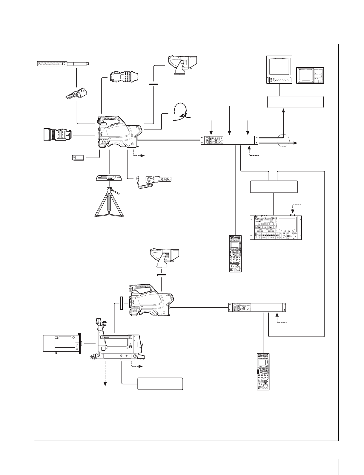
System Configuration Example
Microphone
CAC-12
Microphone
Holder
Zoom Lens
(for ENG/EFP)
“Memory Stick”
VCT-14
Tripod Adaptor
Tr i po d fo r
portable
camera
HDVF-200/C35W
Viewfinder
HSC-300/HXC-100
HD Color Camera
HDVF-550/C550W/C730W
Viewfinder
VF attachment shoe
Intercom headset
b)
Triax cable
Power supply
for a script light
DC 12 V
(Max. 0.5 A)
CAC-6
Return Video Selector
c)
HSCU-300/
Camera Control
Unit
a)
Sync input
Return video input
Prompter video input
LAN cable
LAN cable
CCA-5 cable
Picture
Monitor
Wavefor m
Monitor
BNC BNC
Video router
Video output
HD-SDI/SD-SDI/VBS
to router/switcher
AC power
Hub
AC power
HDVF-550/C550W/C730W
Viewfinder
VF attachment shoe
Camera hangers
Zoom Lens
(for studio use)
General-purpose power supply
DC 12 V (Max. 5A)
a) Supplied with the HDVF-550/C550W/C730W, Part No.: A-7612-405-E
An HXC-100 and HSCU-300 can be connected if both units are of version
b)
1.10 or later.
c) 900 m (2953 ft) when an HSC-300 is connected or 600 m (1969 ft) when an
HXC-100 is connected at maximum and 50 m (164 ft) at minimum when using
Fujikura 8.5-mm dia. cables.
For information of other cables, see “Triax transmission distances (when an
d)
e)
a)
Triax cable
HSC-300
HD Color Camera
HDLA1500-series
Large Lens Adaptor
Power supply for a script light
DC 12 V (Max. 1.5 A)
BKP-7911
Script Holder
MSU-1000/1500
Master Setup Unit
RCP-1000-series
Remote Control
Pane l
HSCU-300
c)
HSC-300 is connected)” (page 24) or “Triax transmission
distances (when an HXC-100 is connected)” (page 24).
d) Supplied with the HDLA1500/1505, Part No.: A-1128-405-A
e) For general-purpose DC 12 V output, the serial number must be
the following or higher:
HDLA1500: 13001 or 43001, HDLA1503: 52001,
HDLA1505: 11001 or 41001 or 401001, HDLA1507: 401001
Camera Control Unit
RCP-1000-series
Remote Control
Pane l
AC power
CCA-5 cable
LAN cable
Overview
7
Locations and Functions of Parts
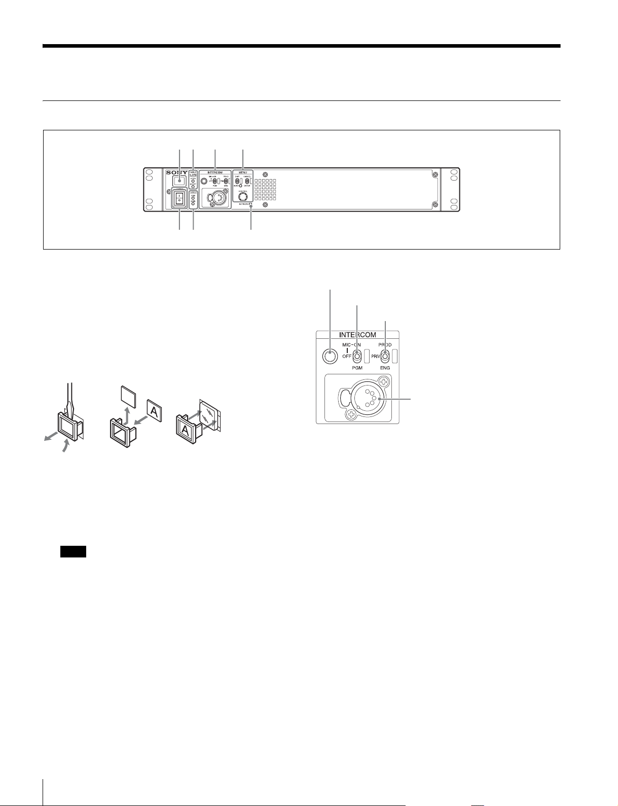
Front Panel
a
bc d
ef g
a Tally light
Turns on red to indicate a red tally signal is being received
(such as when the picture from the camera connected to the
CCU is being used). When the CALL button on the camera,
the MSU-1000/1500 Master Setup Unit, or the RCP-1000series Remote Control Panel is pressed, the light turns off if lit
or turns on if not lit.
Turns on green to indicate a green tally signal is being
received.
A number plate supplied with the CCU can be attached here
(see the following figure).
b CABLE ALARM indicators
OPEN: Turns on when a camera is not connected (open
circuit) to the CAMERA connector on the rear panel via a
triax cable. While on, the CCU does not supply any power
to the camera.
It flashes when there is a problem with the transmission
between the camera and the CCU.
Note
It may also turn on when using the camera with an external DC
supply.
SHORT: Turns on when there is an overcurrent condition
(short circuit) on the triax cable. While on, the CCU does
not supply any power to the camera.
c INTERCOM audio input/output and control block
INTERCOM (intercom adjustment) knob
MIC/PGM (microphone/program) switch
INTERCOM (intercom select) switch
INTERCOM
connector
• INTERCOM (intercom adjustment) knob
Adjusts the headset audio level.
• MIC/PGM (microphone/program) switch
ON: Turns the headset microphone on.
OFF: Turns the headset microphone off.
PGM: Selects program audio output. In this mode, the
INTERCOM knob adjusts the headset program audio level.
• INTERCOM (intercom select) switch
Selects the intercom signal input/output connection source for
the INTERCOM connector on the rear panel.
PROD: Connects the producer line.
PRIV: Disconnects both the producer line and engineer line,
allowing private communication between CCU and camera
only.
ENG: Connects the engineer line.
• INTERCOM connector (XLR 5-pin)
Intercom headset connection.
Locations and Functions of Parts
8
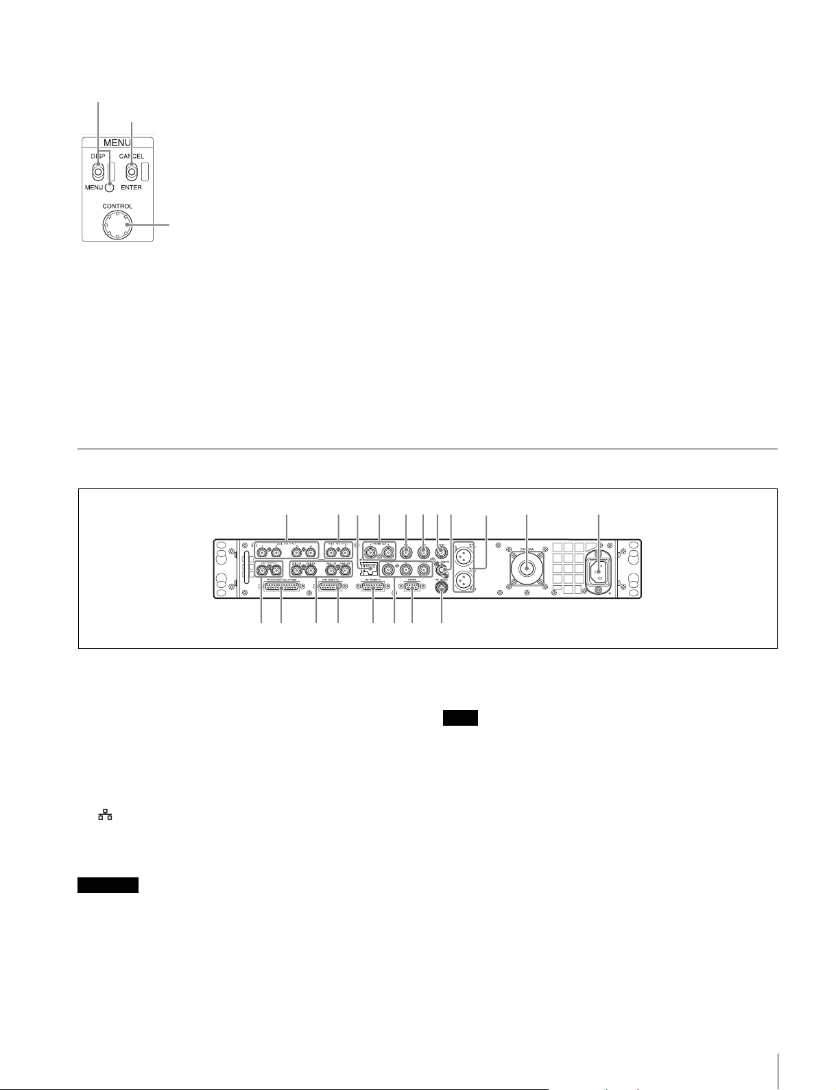
d MENU control block
DISP/MENU (display/menu) lever and indicator
CANCEL/ENTER lever
CONTROL knob
• DISP/MENU (display/menu) lever and indicator
Selects the status display or setup menu display. In setup
menu mode, the indicator turns on.
• CANCEL/ENTER lever
In setup menu mode, used to cancel and enter settings.
• CONTROL knob (rotary encoder)
In status screen mode, used to change the displayed page.
In setup menu mode, used to move the cursor on a page and
to change menu settings. Pressing the CONTROL knob
performs the same function as setting the CANCEL/ENTER
lever to the ENTER position.
e POWER switch
Switches the power for the entire system on and off, including
the CCU, camera, and the RCP-1000-series Remote Control
Panel connected to the REMOTE connector on the rear panel.
Pressing the “?” side turns the camera system on, and
pressing the “a” side turns it off.
f POWER indicator
CAM: Turns on when power is supplied to the camera.
MAIN: Turns on when the CCU power supply is turned on. It
flashes when there is a problem with the fan.
g NETWORK indicator
Displays the network system connection status.
On: Indicates that external control equipment (MSU-
1000/1500 Master Setup Unit, RCP-1000-series Remote
Control Panel, or other device) is connected.
Flashing: Indicates a connection problem with the external
control equipment (MSU-1000/1500 Master Setup Unit,
RCP-1000-series Remote Control Panel, or other device).
Off: Indicates that a LAN cable is not connected or that the
network system connection parameters have not been set.
See “Network diagnostics” on page 12 and “NETWORK
SETTINGS menu” on page 22.
Rear Panel
a
lm no pqr s
a SDI OUTPUT 1 to 4 connectors (BNC type)
Outputs the camera signals in HD SDI or SD SDI signal
format.
The SDI OUTPUT 3 and SDI OUTPUT 4 connectors can also
output signals with superimposed character or marker display.
b VBS OUTPUT 1, 2 (composite video signal 1, 2)
connectors (BNC type)
Outputs (2-system) the camera signals in composite signal
format.
c LAN jack (RJ-45, 8-pin)
Connects to a LAN hub (10BASE-T/100BASE-TX), when
using a network connection, via a LAN cable (shielded type,
category 5 or higher).
CAUTION
• For safety, do not connect the connector for peripheral device wiring
that might have excessive voltage to this port. Follow the
instructions for this port.
• When you connect the LAN cable of the unit to peripheral device,
use a shielded-type cable to prevent malfunction due to radiation
noise.
bc d efgh i j k
d PROMPTER (teleprompter input 1, 2) connectors
(BNC type)
Inputs the VBS signals for the teleprompter.
Note
When an HXC-100 is connected, only the PROMPTER 1
connector is enabled.
e PIX (picture monitor output) connector (BNC type)
Outputs a video signal for a picture monitor. It can also output
a signal with superimposed character display.
f WF (waveform monitor output) connector (BNC type)
Outputs a video signal for a waveform monitor.
g SYNC (sync signal output) connector
Outputs a sync signal for connection to the sync signal input
connector of a waveform monitor or picture monitor.
h REMOTE connector (8-pin)
Transmits and receives control signals from a MSU-1000/1500
Master Setup Unit, CNU-700 Camera Command Network
Unit, or RCP-1000-series Remote Control Panel via a CCA-5
cable (optional). It also supplies power when connected to an
RCP-1000-series Remote Control Panel.
Locations and Functions of Parts
9
 Loading...