

Sony HSC-300 Operation Manual

HD COLOR CAMERA
HSC-300
The supplied CD-ROM includes Operation Manual for the HSC-300 HD Color
Camera (English, French, German, Italian, and Spanish versions) in PDF format.
For more details, see “Using the CD-ROM Manuals” on page 8.
OPERATION MANUAL [English]
1st Edition (Revised 1)

Before operating the unit, please read this manual thoroughly
and retain it for future reference.
WARNING
To reduce the risk of fire or electric shock,
do not expose this apparatus to rain or
moisture.
To avoid electrical shock, do not open the
cabinet. Refer servicing to qualified
personnel only.
AVERTISSEMENT
Afin de réduire les risques d’incendie ou
d’électrocution, ne pas exposer cet
appareil à la pluie ou à l’humidité.
Afin d’écarter tout risque d’électrocution,
garder le coffret fermé. Ne confier
l’entretien de l’appareil qu’à un personnel
qualifié.
WARNUNG
Um die Gefahr von Bränden oder
elektrischen Schlägen zu verringern, darf
dieses Gerät nicht Regen oder Feuchtigkeit
ausgesetzt werden.
Um einen elektrischen Schlag zu
vermeiden, darf das Gehäuse nicht
geöffnet werden. Überlassen Sie
Wartungsarbeiten stets nur qualifiziertem
Fachpersonal.
All interface cables used to connect peripherals must be
shielded in order to comply with the limits for a digital device
pursuant to Subpart B of Part 15 of FCC Rules.
This device complies with Part 15 of the FCC Rules. Operation
is subject to the following two conditions: (1) this device may
not cause harmful interference, and (2) this device must
accept any interference received, including interference that
may cause undesired operation.
For the customers in Canada
This Class A digital apparatus complies with Canadian ICES-
003.
Pour les clients au Canada
Cet appareil numérique de la classe A est conforme à la
norme NMB-003 du Canada.
For the customers in Europe
This product with the CE marking complies with both the EMC
Directive and the Low Voltage Directive issued by the
Commission of the European Community.
Compliance with these directives implies conformity to the
following European standards:
• EN60950-1: Product Safety
• EN55103-1: Electromagnetic Interference (Emission)
• EN55103-2: Electromagnetic Susceptibility (Immunity)
This product is intended for use in the following
Electromagnetic Environments:
E1 (residential), E2 (commercial and light industrial), E3
(urban outdoors), E4 (controlled EMC environment, ex. TV
studio).
The manufacturer of this product is Sony Corporation, 1-7-1
Konan, Minato-ku, Tokyo, Japan.
The Authorized Representative for EMC and product safety is
Sony Deutschland GmbH, Hedelfinger Strasse 61, 70327
Stuttgart, Germany. For any service or guarantee matters
please refer to the addresses given in separate service or
guarantee documents.
For the customers in the U.S.A.
This equipment has been tested and found to comply with the
limits for a Class A digital device, pursuant to Part 15 of the
FCC Rules. These limits are designed to provide reasonable
protection against harmful interference when the equipment is
operated in a commercial environment. This equipment
generates, uses, and can radiate radio frequency energy and,
if not installed and used in accordance with the instruction
manual, may cause harmful interference to radio
communications. Operation of this equipment in a residential
area is likely to cause harmful interference in which case the
user will be required to correct the interference at his own
expense.
You are cautioned that any changes or modifications not
expressly approved in this manual could void your authority to
operate this equipment.
2
Pour les clients en Europe
Ce produit portant la marque CE est conforme à la fois à la
Directive sur la compatibilité électromagnétique (EMC) et à la
Directive sur les basses tensions émises par la Commission
de la Communauté Européenne.
La conformité à ces directives implique la conformité aux
normes européennes suivantes :
• EN60950-1 : Sécurité des produits
• EN55103-1 : Interférences électromagnétiques (émission)
• EN55103-2 : Sensibilité électromagnétique (immunité)
Ce produit est prévu pour être utilisé dans les environnements
électromagnétiques suivants :
E1 (résidentiel), E2 (commercial et industrie légère), E3
(urbain extérieur) et E4 (environnement EMC contrôlé, ex.
studio de télévision).
Le fabricant de ce produit est Sony Corporation, 1-7-1 Konan,
Minato-ku, Tokyo, Japon.
Le représentant autorisé pour EMC et la sécurité des produits
est Sony Deutschland GmbH, Hedelfinger Strasse 61, 70327
Stuttgart, Allemagne. Pour toute question concernant le

service ou lagarantie, veuillez consulter les adresses
indiquées dans les documents de service ou de garantie
séparés.
Table of Contents
Für Kunden in Europa
Dieses Produkt besitzt die CE-Kennzeichnung und erfüllt die
EMV-Richtlinie sowie die Niederspannungsrichtlinie der EGKommission.
Angewandte Normen:
• EN60950-1: Sicherheitsbestimmungen
• EN55103-1: Elektromagnetische Verträglichkeit
(Störaussendung)
• EN55103-2: Elektromagnetische Verträglichkeit
(Störfestigkeit)
Für die folgenden elektromagnetischen Umgebungen:
E1 (Wohnbereich), E2 (kommerzieller und in beschränktem
Maße industrieller Bereich), E3 (Stadtbereich im Freien) und
E4 (kontrollierter EMV-Bereich, z.B. Fernsehstudio).
Der Hersteller dieses Produkts ist Sony Corporation, 1-7-1
Konan, Minato-ku, Tokyo, Japan.
Der autorisierte Repräsentant für EMV und Produktsicherheit
ist Sony Deutschland GmbH, Hedelfinger Strasse 61, 70327
Stuttgart, Deutschland. Bei jeglichen Angelegenheiten in
Bezug auf Kundendienst oder Garantie wenden Sie sich bitte
an die in den separaten Kundendienst- oder
Garantiedokumenten aufgeführten Anschriften.
For the State of California, USA only
Perchlorate Material - special handling may apply, See
www.dtsc.ca.gov/hazardouswaste/perchlorate
Perchlorate Material : Lithium battery contains perchlorate.
For the customers in Taiwan only
Overview .................................................................... 4
Features ......................................................................... 4
System Configuration ..................................................... 6
Standalone operation example ................................. 6
System operation example (two cameras with Camera
Control Units) ........................................................ 7
Using the CD-ROM Manuals .......................................... 8
Parts Identification .......................................................... 8
Front right ................................................................. 8
Front left .................................................................... 9
Rear ........................................................................ 10
Operation panel ...................................................... 10
Connector panel ..................................................... 11
Installation ............................................................... 13
Connecting a Camera Control Unit (CCU) ................... 13
Attaching a Lens ........................................................... 13
Attaching a Viewfinder .................................................. 14
Attaching a Microphone ................................................ 15
Mounting the Camera to a Tripod ................................. 15
Adjusting the Shoulder Pad Position ............................ 16
Preparatory Settings............................................... 17
Adjusting the Black Balance and White Balance .......... 17
Setting the Electronic Shutter ....................................... 18
Setting the Local Time .................................................. 19
Adjusting the Flange Focal Length ............................... 19
Setting the Focus Assist Function ................................ 20
Setting the Camera Outputs ......................................... 21
Outputting a Trunk Signal ............................................. 22
Menus....................................................................... 23
Displaying Menu Pages ................................................ 23
Setting the Menu .......................................................... 23
Editing the USER Menu ................................................ 25
OPERATION Menu ...................................................... 27
PAINT Menu ................................................................. 31
MAINTENANCE Menu ................................................. 33
FILE Menu .................................................................... 36
DIAGNOSIS Menu ........................................................ 37
Appendices.............................................................. 38
Precautions .................................................................. 38
Error Messages ............................................................ 39
Using a “Memory Stick” ................................................ 39
Specifications ............................................................... 40
Menu Tree .................................................................... 42
Table of Contents
3

Overview
The HSC-300 is a 2/3-type high-definition portable video
camera equipped with CCD units for 2,200,000 pixels, which
can be used as a standalone camera as well as in a multicamera studio system in combination with the HSCU-300 or
HXCU-100
(MSU).
The camera incorporates the latest image capturing device
and digital signal-processing LSI, and it performs newly
developed digital transmission with the camera control unit
(CCU), thus yielding high picture quality and high stability in
image creation in addition to superior camera functions and
operability.
1) An HSC-300 and HXCU-100 can be connected if both units are of
version 1.10 or later.
1)
Camera Control Unit and a master setup unit
Operable in an HDLA large-lens adaptor
The camera can be mounted in an HDLA1500-series largelens adaptor. Featuring the characteristics of requiring no
cable connection and no adjustments, switching between
large-lens studio operation and portable operation can be
easily performed, enabling flexible application with high
mobility.
ND/CC dual optical servo filters mounted
The camera incorporates ND and CC optical servo filter units,
four each, which can be remotely controlled from an external
control device, such as a remote control panel (RCP) or a
master setup unit (MSU).
Position-adjustable shoulder pad
The position of the shoulder pad can be adjusted for stable
shooting according to the build of the camera operator, the
type of lens in use, or the shooting style.
A low-repulsion shoulder pad (position fixed) is available as an
option. (Part No.: A-8286-346-A)
Features
High picture quality and high performance
The latest 2/3-type Progressive IT CCD units for 2,200,000
pixel achieve high sensitivity and low smear. In addition, the
14-bit A/D converter and an original developed signalprocessing LSI provide high picture quality of optimal grade.
Multiple formats
The camera covers 1080/59.94i, 720/59.94P, 1080/50i, and
720/50P.
With its wide-range down-converter, the camera also enables
output of high-quality SD signals (525i/625i) from the camera
and the connected CCU, establishing an optimum camera
system for SD-system operations.
Newly designed integrated unit with low center
of gravity
The camera has stylish appearance with low-slung design.
When used in combination with the HDLA1500-series largelens adaptor, it permits a viewfinder to be mounted at a low
position, making the viewfinder position closer to the optical
axis of the lens.
Optimized handle shape and VF slide
mechanism for stable shooting
A new handle design has been adopted. A slight protrusion of
the upper front part of the handle enables stable holding of the
camera while you are shooting, by holding the front part of the
handle. Furthermore, a slide mechanism is located at the
viewfinder attachment position. Any difference in weight
balance caused by having a different lens attached can be
counteracted by adjusting the viewfinder attachment position,
in combination with the movable shoulder pad position. This
provides the best balance for shooting with the camera on your
shoulder.
Function-assignable switches
The camera has buttons to which various functions can be
assigned on the side panel and the rear. You can activate your
desired function, such as electronic color-temperature
conversion, instantly when shooting by assigning it to one of
these buttons in advance.
Buttons on the handle are also available as function
assignable switches.
Auto Lens Aberration Compensation function
The Auto Lens Aberration Compensation function (ALAC) is
provided with this camera. This automatically reduces
chromatic aberration of magnification when a lens that
supports auto aberration compensation is attached.
For details on lenses supporting auto aberration
compensation, contact a Sony sales representative or Sony
service representative.
Focus assist functions
The VF detail function and focus assist indicator function
facilitate focusing.
VF detail
Various functions are provided for the VF detail signal, which
can be added only on images on the viewfinder screen in order
to facilitate focusing in various situations: Functions for
coloring the VF detail signal, flickering the VF detail signal by
adding modulation, thickening the VF detail signal, and
automatically compensating the VF detail level according to
the zoom position.
Focus Assist Indicator
The focusing level indicator on the viewfinder screen provides
a guide for focusing. The best focus setting can be easily
determined by observing fluctuation of the level indicator as a
guide.
4
Overview

“Memory Stick”
The camera is equipped with a “Memory Stick” port, which
enables setup data storage and software upgrading using a
“Memory Stick.”
1) “Memory Stick” and are trademarks of Sony
Corporation.
1)
operation
Various color-reproduction functions
Selection of multiple gamma tables
Seven types of standard and 4 types of hyper gamma tables
are provided with this camera. The hyper gamma values
enable cinemalike image creations with wide dynamic range,
which are different from those achieved with conventional
video gamma.
1) Safety zone marker: A box-shaped marker displayed on the
viewfinder screen which indicates 80%, 90%, 92.5%, or 95% of the
total screen area
2) Center marker: A cross-shaped marker which indicates the center
of the viewfinder screen
Wide variety of viewfinder display options
Along with items such as operation messages, a zebra
pattern,
settings may also be displayed on the viewfinder screen.
Furthermore, there are various cautionary and warning
indications to be occasionally displayed, making it simple to
check the status of the camera.
1) Zebra pattern: A stripe pattern displayed on the viewfinder screen
1)
a safety-zone marker, and a center marker, camera
which indicates the portions where the video level is above about
70% or 100%. Used to check the video level of the subject.
Multimatrix color correction
In addition to the standard 6-axis matrix function, the camera
has a multimatrix function that permits you to adjust the hue
and chroma for color components in 16-axis directions
independently. This is quite useful in color matching among
multiple cameras.
Knee saturation
Change of hue and decrease in chroma that occur in
highlighted areas can be compensated.
This enables reproduction of natural skin tones under strong
lighting.
Low key saturation
Hue and chroma in low-key zones can be compensated. Thus,
compensation for color reproduction in all zones is enabled in
combination with matrix color compensation and knee
saturation functions.
Versatile detail control functions
Skin-tone detail function
This function allows control (emphasis or suppression) of the
detail level for just a certain hue or chroma area in the image,
by creating a detail gate signal from color components of your
specified hue, such as skin tones.
Digital triax transmission
The camera uses an industry standard dual-shield coaxial
(triax) camera cable for connection between the camera and a
CCU. Newly developed original digital transmission
technology is built into the camera, and high-quality pictures
can be transmitted between the camera and CCU, regardless
of the cable length.
Versatile choices of viewfinders
Multiformat monochrome CRT viewfinders, HDVF-200 (2type) and HDVF-550 (5-type) can be selected for use in studio
and portable systems.
Color LCD viewfinders, HDVF-C35W (3.5-type), HDVFC550W (5-type), and HDVF-C730W (6.5-type), are also
selectable to cover various applications.
Prevention of electrical shock
When the power connection is unsafe, the power supply from
the connected Camera Control Unit will be shut off.
Detail boost-frequency control
The boost frequency can be adjusted from 20 to 30 MHz. This
allows the detail thickness to be set appropriately for the
subject, thus enabling more subtle image expression.
H/V ratio control
The ratio between horizontal and vertical detail can be
adjusted.
White/black limiter
The white and black details can be limited independently.
Easy menu-based setting
Selections and settings for viewfinder display items, safetyzone marker
be made quickly and easily, using setup menus displayed on
the viewfinder screen or an external monitor.
1)
or center marker,
2)
screen size marker, etc. can
Overview
5
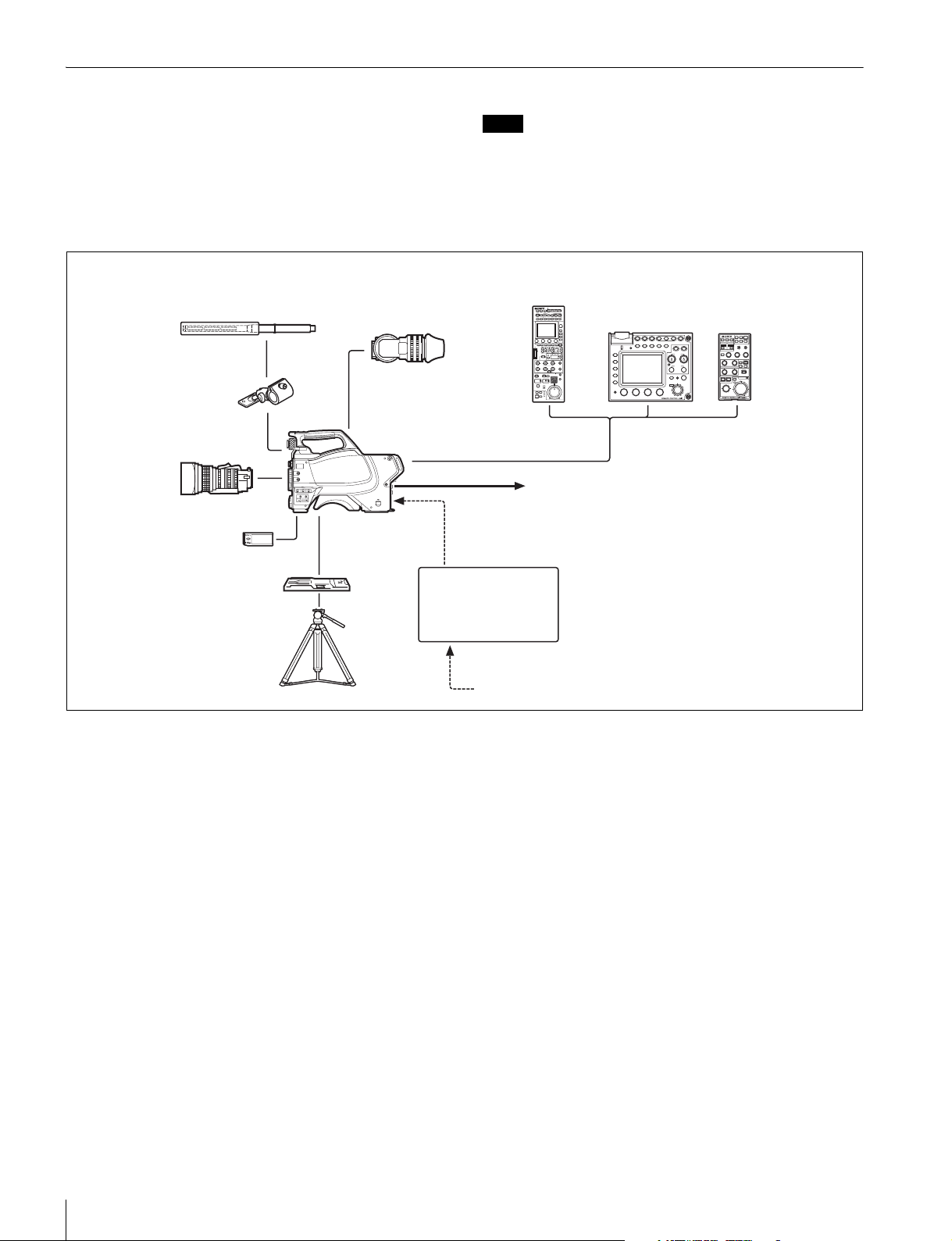
System Configuration
Peripherals and related devices for the camera are shown in
figures.
Standalone operation example
Microphone
HDVF-200/C35W Viewfinder
CAC-12
Microphone
holder
Zoom Lens
(for ENG/EFP)
“Memory Stick”
HSC-300
Note
Production of some of the peripherals and related devices
shown in the figures has been discontinued. For advice on
choosing devices, please contact your Sony dealer or a Sony
sales representative.
RCP-1000-series
Remote Control Panel
CCA-5 cable
Video output
HD-SDI/SD-SDI/VBS
1)
RM-B750/B150
Remote Control Unit
(selectable)
VCT-14
Tripod Adaptor
Tripod for
portable
camera
AC Adaptor
AC-DN10/DN2B
Battery Charger
BC-L70/L160
AC power
1) No subcarrier phase-lock function with respect
to external reference is available for the VBS
signal output from the camera.
6
Overview
System operation example (two cameras with Camera Control Unitsa))
Microphone
CAC-12
Microphone
Holder
Zoom Lens
(for ENG/EFP)
“Memory Stick”
VCT-14
Tripod Adaptor
Tripod for
portable
camera
HDVF-200/C35W
Viewfinder
HSC-300
VF attachment shoe
HDVF-550/C550W/C730W
Viewfinder
VF attachment shoe
Intercom headset
Tr i a x ca b l e
c)
Power supply
for a script light
DC 12 V
(Max. 0.5 A)
CAC-6
Return Video Selector
(mounted to the front
panel of an HXCU-100)
HKCU-FP1
Front Control Panel
HDVF-550/C550W/C730W
Viewfinder
RCP-1000-series
Remote Control
b)
Panel
b)
Return video input
Sync input
HSCU-300/
HXCU-100
d)
Camera Control
Unit
Picture
Monitor
Prompter video input
AC power
LAN cable
LAN cable
CCA-5 cable
MSU-1000/1500
Master Setup Unit
BNC BNC
Video router
Video output
HD-SDI/SD-SDI/VBS
Hub
Waveform
Monitor
to router/switcher
AC power
a)
LAN cable
Camera hangers
Zoom Lens
e)
Triax cable
HSC-300
(for studio use)
HDLA1500-series
Large Lens Adaptor
Power supply for a script light
DC 12 V (Max. 1.5 A)
BKP-7911
General-pur pose power supply
DC 12 V (Max. 5A)
f)
Script Holder
a) Enabled only when an HSCU-300 is connected.
b) Supplied with the HDVF-550/C550W/C730W, Part No.: A-7612-405-E
c) 900 m (2953 ft) when an HSCU-300 is connected or 600 m (1969 ft) when an
HXCU-100 is connected at maximum and 50 m (164 ft) at minimum when using
Fujikura 8.5-mm dia. cables.
For information of other cables, see “About the distances of triax transmission
(when an HSCU-300 is connected)” (page 38) or “About the distances of triax
transmission (when an HXCU-100 is connected)” (page 38).
d)
HSCU-300/HXCU-100
c)
Camera Control Unit
AC power
CCA-5 cable
RCP-1000-series
Remote Control
Panel
d) An HSC-300 and HXCU-100 can be connected if both units
are of version 1.10 or later.
e) Supplied with the HDLA1500/1505, Part No.: A-1128-405-A
f) For general-purpose DC 12 V output, the serial number must be
the following or higher:
HDLA1500: 13001 or 43001, HDLA1503: 52001,
HDLA1505: 11001 or 41001 or 401001, HDLA1507: 401001
Overview
7
Using the CD-ROM Manuals
q
Parts Identification
The supplied CD-ROM includes the operation manuals for the
camera in English, French, German, Italian, and Spanish in
PDF format.
Reading the CD-ROM Manuals
Preparations
The following program must be installed on your computer in
order to read the operation manuals contained on the CDROM.
Adobe Reader Version 6.0 or higher
Memo
If Adobe Reader is not installed, you can download it from the
following URL:
http://www.adobe.com/
Adobe and Adobe Reader are trademarks of Adobe Systems
Incorporated in the United States and/or other countries.
To read the documents
1 Insert the CD-ROM in your CD-ROM drive.
A cover page appears automatically in your browser.
If it does not appear automatically in the browser, doubleclick on the index.htm file on the CD-ROM.
2 Select and click on the manual that you wish to read.
This opens the PDF file.
Memo
The files may not be displayed properly, depending on the
version of Adobe Reader. In such a case, install the latest
version you can download from the URL mentioned in
“Preparations” above.
Note
If you have lost or damaged the CD-ROM, you can purchase
a new one to replace it. Contact your Sony service
representative.
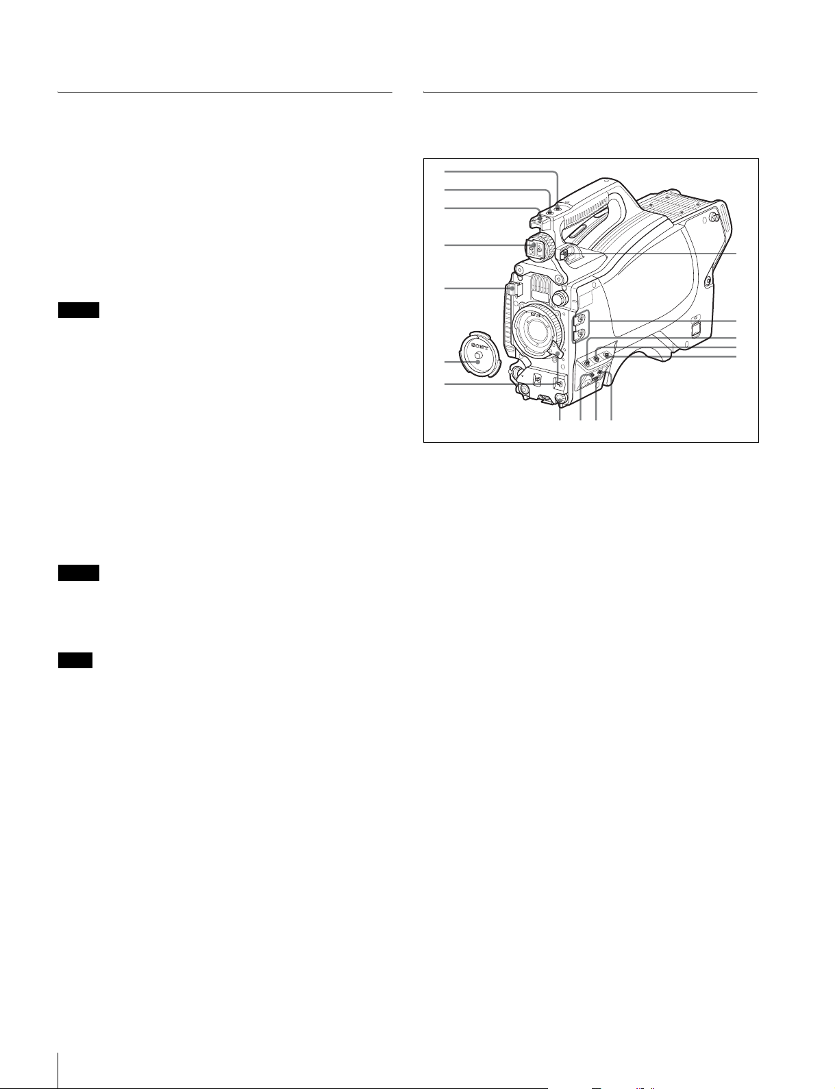
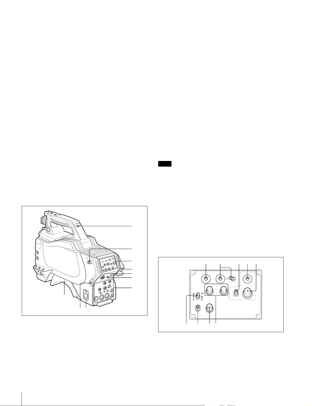
Front right
1
2
3
4
5
6
7
qf qd
qg
h
a INCOM (intercom) button (UC model)/ENG (engineer
line) button (CE model)
UC model: The intercom microphone is on while this button is
held pressed.
CE model: The intercom microphone is on and the engineer
line is selected while this button is held pressed.
You can also assign other functions with a menu operation.
b RET 1 (return video 1) button
The return video 1 signal from the CCU is monitored on the
viewfinder screen while this button is held pressed. It functions
the same as the RET 1 button on the operation panel (page
10) on the rear of the camera.
You can also assign other functions with a menu operation.
c Accessory shoe
To attach an accessory using a 1/4-inch screw.
d Viewfinder shoe
Mount a viewfinder.
For details, see “Attaching a Viewfinder” (page 14).
8
9
0
qa
qs
8
e Lens cable clamp
To secure the cable of the lens (optional).
f Lens mount cap
The cap can be removed by moving the lens fixing lever
upward. Always keep the lens mount covered with this cap
when a lens is not attached.
g Lens fixing lever
Move the lever down to secure the lens in the lens mount.
For details, see “Attaching a Lens” (page 13).
h Viewfinder front-rear position lock lever
The viewfinder position can be adjusted forward or backward
when the lock is released by the lever.
For details on the adjustment, see “To adjust the viewfinder’s
front-rear position” (page 14).
Overview
i Assignable buttons
0qa9
1
2
4
3
5
6
7
8
You can assign a function to the upper button by using
ASSIGNABLE 1 and the lower button with ASSIGNABLE 2 on
the <SWITCH ASSIGN1> page of the OPERATION menu.
j GAIN switch
To select the gain of the video amplifier based on lighting
conditions when the camera is used in standalone status
without connecting a CCU.
When shipped from the factory, the values set are L = 0 dB,
M = 6 dB, and H = 12 dB.
k AUTO KNEE and output signal selection switch
To select the signal (color-bar signal or camera’s video signal)
to be used as output to a VTR, the viewfinder, or a video
monitor when the camera is used in standalone status without
connecting a CCU.
When the camera’s video signal is being used as output, the
auto knee function can be selected.
BARS/OFF: Output is a color-bar signal.
CAM/OFF: Output is the camera’s video signal. The auto knee
circuit is disabled.
CAM/ON: Output is the camera’s video signal. The auto knee
circuit is enabled.
l WHITE BAL (white balance memory selection) switch
To select the white balance adjustment method or the memory
used to store the adjusted value when the camera is used in
standalone status without connecting a CCU.
PRST (preset): White balance is adjusted to a preset value
corresponding to a color temperature of 3200K.
A: To select memory A.
B: To select memory B.
o STATUS/CANCEL switch
STATUS: To display status information of this camera in the
viewfinder when no menu is displayed with the DISPLAY/
MENU switch set to DISPLAY.
CANCEL: To cancel changed settings or return the display to
the previous menu when a menu is displayed in the
viewfinder.
p Menu control knob (rotary encoder)
Used to select settings from menus displayed on the
viewfinder screen (by rotating it) and to confirm settings (by
pushing it).
This knob functions the same as that on the rear operation
panel.
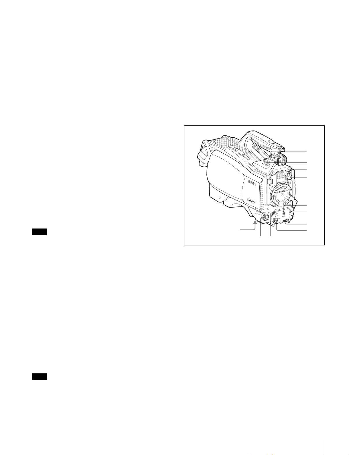
Front left
Note
When a CCU or an external control device, such as an RCP/
RM or MSU, is connected, the functions of 0 to qs are
controlled from the external device, and the controls on the
camera are disabled.
m DISPLAY/MENU switch
Select the display on the viewfinder screen.
DISPLAY: To display various textual information and markers,
such as messages showing the camera settings and
operating status, the center marker, and the safety zone
marker, in addition to camera images.
OFF: To not display textual information and markers.
MENU: To display menus for camera settings, in addition to
camera images.
The switch functions the same as the DISPLAY/MENU switch
on the rear operation panel.
n “Memory Stick” slot and access lamp
When you insert a “Memory Stick” into the slot, the access
lamp lights in green.
The lamp is lit in red while writing/reading data to/from the
“Memory Stick.”
Note
When the access lamp is lit in red, do not insert/remove the
“Memory Stick” or turn off the camera.
a Shoulder strap fitting post
Attach one end of a shoulder strap (optional, part No. A-6772374-C) to this fitting post and the other end to the fitting post
on the other side of the camera.
b VF (viewfinder) connector (20-pin)
Connect the cable of the viewfinder (optional).
c CC filter select knob
To select the built-in CC filters (A: cross, B: 3200K, C: 4300K,
D: 6300K).
d ND filter select knob
To select the built-in ND filters (1: clear, 2: 1/4 ND, 3: 1/16 ND,
4: 1/64 ND).
e SHUTTER switch
When the camera is used in standalone status without
connecting a CCU, use this switch to turn ON or OFF the
electronic shutter and change (SEL) the shutter speed and
shutter mode.
For details, see “Setting the Electronic Shutter” (page 18).
f AUTO W/B BAL (white and black balance automatic
adjustment) switch
To automatically adjust white and black balance when the
camera is used in stand-alone status without connecting to a
CCU.
WHT: To automatically adjust white balance.
Overview
9
BLK: To automatically adjust black balance.
908
6789
For details, see “Adjusting the Black Balance and White
Balance” (page 17).
g INTERCOM LEVEL control
To adjust the intercom/earphone volume level.
The intercom level adjustment is enabled when the LEVEL/
MIC switch on the UC-type operation panel (page 11) or the
LEVEL switch on the CE-type operation panel (page 11) on
the rear is set to “FRONT.”
h RET (return video) button
When this button is pressed, the picture on the viewfinder
changes to the return video signal selected with the RET 2/3/
4 select switch (page 10) on the operation panel on the rear of
the camera.
You can also assign other functions with a menu operation.
i LENS connector (12-pin)
Connect the lens cable. The camera can control the lens
functions through this cable.
j MIC 1 IN (microphone 1 input) connector (XLR 3-pin)
Connect a microphone.
This connector and the AUDIO IN CH1 connector are
alternately activated with the MIC 1 select switch on the rear
connector panel.
k Tripod mount (bottom)
Attach the VCT-14 Tripod Adaptor when mounting the camera
on a tripod.
For details, see “Mounting the Camera to a Tripod” (page 15).
Rear
b Shoulder strap fitting post
c Operation panel (See “Operation panel”.)
d Camera Control Unit (CCU) connector (triax
connector)
Connect an HSCU-300 or HXCU-100 Camera Control Unit
using a triax cable.
e INTERCOM connector (XLR 5-pin)
Connect an XLR 5-pin headset for input and output of intercom
audio signals.
The connector can be used for communication over the
engineer line when the camera is in standby status.
f EARPHONE jack (stereo minijack)
For connecting an earphone for output of the intercom audio.
g Connector panel (See “Connector panel” on page 11.)
h CAMERA POWER switch and indicator
CCU: To operate on power supply via the connected CCU.
EXT: To operate on power supply through the DC IN
connector.
The indicator is lit in green during operation. It is lit in red while
standby power is being supplied from the CCU, even if the
switch is set to OFF.
Note
When a CCU is connected, external power supply (EXT)
cannot be used.
i CALL button
When you press this button, the red tally lamp of the
connected external control device (RCP/RM, MSU, etc.) will
light. Use to call the operator of the external control device.
1
2
3
4
5
6
7
a Tally lamp and switch
ON: The tally lamp lights when a tally signal is input to the
connected CCU or a call signal is generated in response to
pressing of a CALL button.
OFF: The tally lamp is prevented from lighting.
j Shoulder pad
You can adjust the position on your shoulder.
For details, see “Adjusting the Shoulder Pad Position” (page
16).
Operation panel
UC type: Model for NTSC areas
12 345
RET1 RET
PGM1
MICLEVEL
ON
REAR
FRONT
OFF
INCOM
PROD
ENG
INTERCOM EARPHONE
a RET 1 (return video 1) button
The return video signal is displayed on the viewfinder screen
while the button is held pressed.
b RET (return video) button and 2/3/4 (return video 2/3/4)
select switch
When other return video systems are used in addition to return
video 1, the signal selected with the 2/3/4 switch is displayed
PGM2
234
OFF
DISPLAY
MENU
ASSIGNABLE
Overview
10
on the viewfinder screen while holding the RET button
12 345
678 0 q
9
pressed.
Note
The RET 1 button has priority over the RET (2/3/4) button if
both buttons are pressed.
c DISPLAY/MENU switch
This switch functions the same as the DISPLAY/MENU switch
on the front (page 9).
d ASSIGNABLE button
You can assign a function with ASSIGNABLE REAR on the
<SWITCH ASSIGN1> page of the OPERATION menu.
e Menu control knob (rotary encoder)
This knob functions the same as the menu control knob on the
front (page 9).
f LEVEL/MIC (intercom level control/microphone)
switch
To determine whether to use the INTERCOM LEVEL control
(page 10) on the front and to turn the intercom headset
microphone ON/OFF.
Switch position INTERCOM LEVEL
control on the front
REAR/ON Inactive ON
REAR/OFF OFF
FRONT/OFF Active
Headset microphone
g Line select switch
To select the intercom line:
PROD: Producer line
ENG: Engineer line
h INCOM (intercom) level control
To adjust the intercom audio listening level.
i PGM1 (program 1) and PGM2 (program 2) controls
To adjust the audio listening level of program 1 or program 2,
respectively.
CE type: Models for PAL areas
RET1 RET
PGM1
MIC
LINE
PROD
OFF
ENG
LEVEL
ENG PROD TRACKER
REAR
FRONT
INTERCOM EARPHONE
1 to 5 are the same as those of the UC type.
f MIC LINE (intercom microphone line) switch
To select the talk line for intercom:
PROD: To talk over the producer line
OFF: To turn off the headset microphone for the intercom line
ENG: To talk over the engineer line
PGM2
234
OFF
DISPLAY
MENU
ASSIGNABLE
a
g LEVEL switch
REAR: The intercom audio listening level is adjusted with the
ENG or PROD control on this panel.
FRONT: The levels adjusted on the rear panel can be totally
adjusted with the INTERCOM LEVEL control on the front.
h ENG (engineer line) control
To adjust the intercom audio listening level of the engineer line.
i PGM1 (program 1) and PGM2 (program 2) controls
To adjust the audio listening level of program 1 or program 2,
respectively.
j PROD (producer line) control
To adjust the intercom audio listening level of the producer
line.
k TRACKER control
To adjust the intercom audio listening level at the TRACKER
connector on the connector panel.
Connector panel
1234567
REAR
PROMPTER
/GENLOCK
/RET IN
+
48V
MICLINE
REMOTE
TEST
OUT
SDI
RET CTRL
+
48V
MICLINE
TRACKER
MIC1
FRONT
AUDIO IN
CH1 CH2
DC IN
DC OUT
10.5-17V
890qa
a DC IN (DC power supply input) connector (XLR 4-pin)
For connection to an AC-DN10 AC Adaptor, etc. to supply
power to the camera. (When a CCU is connected, this
connector cannot be used.)
b DC OUT (DC power supply output) connector (4-pin)
To supply power to a script light or equivalent (12 V DC, max.
0.5 A).
c TRACKER connector (10-pin)
For external interfaces, such as intercom and tally.
d RET CTRL (return control) connector (6-pin)
For connection to a CAC-6 Return Video Selector.
e PROMPTER/GENLOCK/RET IN (prompter signal
output/external sync signal input/VBS return input)
connector (BNC type)
• When a CCU is connected, this connector outputs a VBS
prompter 1 signal.
• When the camera is used in standalone status without
connecting a CCU, use this connector for input of an
external sync signal (BB or 3-level sync). If a VBS signal is
input, you can check the input image by pressing the RET
button.
Overview
11

Notes
• Even when a BB signal is used for the external sync signal,
no subcarrier phase-lock function is available for the VBS
output signal.
• As PROMPTER is set to PWR SAVE at the factory, a
prompter signal is not output. Set it to ACTIVE on the
POWER SAVE page of the MAINTENANCE menu.
f REMOTE connector (8-pin)
For connection to an RM-B150/B750 Remote Control Unit,
RCP-1000-series Remote Control Panel, or MSU-1000/1500
Master Setup Unit.
Note
When a CCU is used in combination, this connector functions
as the trunk signal input/output. Do not connect any remote
control device to this connector.
g TEST OUT connector (BNC type)
To output an analog signal.
This supplies a VBS signal, a VBS prompter 2 signal (only
when an HSCU-300 is connected), an HD-Y signal equal to
the signal output from the VF connector, an HD-SYNC signal,
or an SD-SYNC signal, depending on which of these you have
selected on the menu.
Note
The VBS output signal has no subcarrier phase-lock function
with respect to external sync signals.
h AUDIO IN CH1 connector (XLR 3-pin) and input select
switch
Connect a channel 1 audio signal and set the switch according
to the connected source device.
LINE: When a line-level (0 dBu) signal source is connected
MIC: When an external microphone is connected
+48V: To supply power of +48 V to the connected external
microphone
i MIC 1 (microphone 1) select switch
Select the microphone for channel 1.
FRONT: To use the microphone connected to the MIC 1 IN
connector
REAR: To use the microphone connected to the AUDIO IN
CH1 connector
Notes
• As SDI OUT is set to PWR SAVE at the factory, an SDI
signal is not output. Set it to ACTIVE on the POWER SAVE
page of the MAINTENANCE menu.
• Only a signal of the format selected on the CCU for the input
signal can be output from the camera as the prompter
signal.
The formats which can be selected on the CCU are of the
following 4 types:
— Analog VBS × 2 channels
—SD-SDI × 1 channel
— HD-SDI × 1 channel
— VBS-Y only × 1 channel (LOW LATENCY)
j AUDIO IN CH2 connector (XLR 3-pin) and input select
switch
Connect a channel-2 audio signal and set the switch according
to the connected source device in the same manner as with
channel 1.
k SDI (serial digital interface) connector (BNC type)
For HD-SDI or SD-SDI signal output.
You can select from among camera line signal, return signal,
VF signal, and SDI prompter signal (only when an HSCU-300
is connected) for the output with a menu operation.
Overview
12
Installation
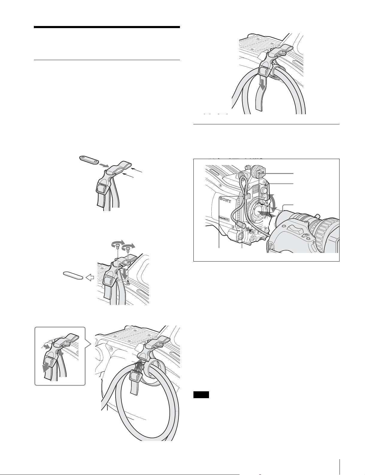
Connecting a Camera Control Unit (CCU)
When operating the camera in a system with a CCU, connect
between the CCU connector of the camera and the CAMERA
connector of the CCU, using a triax cable.
When required, secure the cable, using the supplied cable
clamp belt.
4 Adjust the length by pulling down the end of the belt.
To use the cable clamp belt
1 Insert the belt bracket C into hole A or B of the cable
clamp belt.
C
B
A
2 1 Remove the back screw-hole cover on the top of
the camera and 2 secure the cable clamp belt to the
camera, using the two supplied screws (+B3×10).
2
1
Attaching a Lens
For information on handling lenses, refer to the operation
manual for the particular lens
V
F
B
A
1
C
3
2
R
E
T
T
T
U
H
H
W
S
S
F
F
O
N
K
L
B
E
L
N
O
L
E
S
T
L
E
E
R
V
E
L
M
O
C
R
E
T
E
IN
5
M
I
C
4
1 Push the lens fixing lever A upward and remove the
lens mount cap from the lens mount.
2 Align the lens’ alignment pin C with the notch B in
the upper part of the lens mount and insert the lens
into the mount.
3 1 Release the buckle, 2 bundle the cable with the
belt, 3 then lock the buckle again.
1
3
2
3 While supporting the lens, push the lens fixing lever
A downward to secure the lens.
4 Connect the lens cable to the LENS connector.
5 Secure the lens cable with the cable clamp.
To use a large studio-use lens
A large studio-use lens can be used with this camera by
mounting the camera on an optional HDLA1500-series Large
Lens Adaptor.
Note
When attaching the camera hangers to the camera, always
use the screws (+B4×10) supplied with the lens adaptor.
For details, refer to the operation manual supplied with the
HDLA1500-series adaptor.
Installation
13
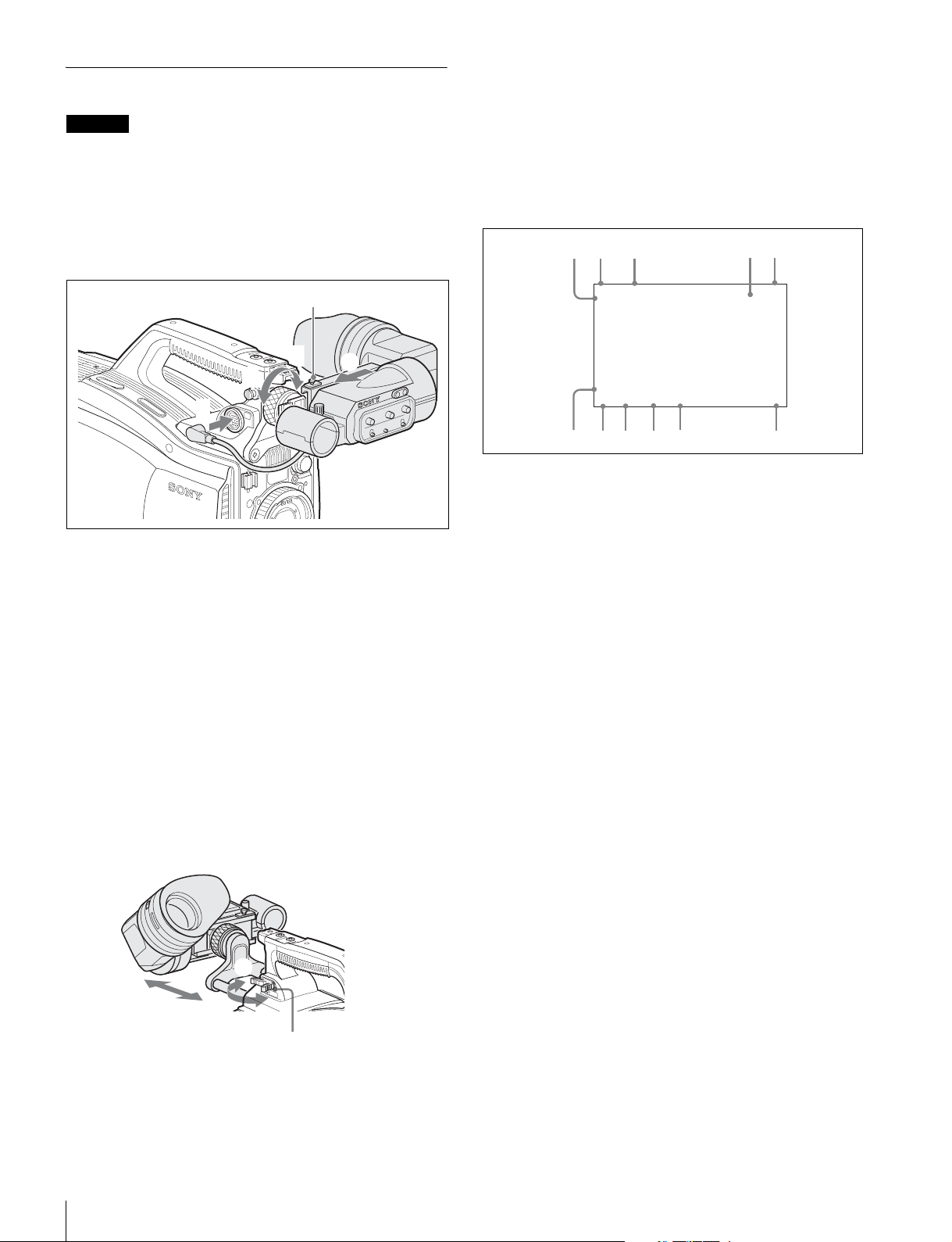
Attaching a Viewfinder
Caution
When the viewfinder is attached, do not leave the camera with
the eyepiece facing the sun. Direct sunlight can enter through
the eyepiece, be focused in the viewfinder and cause fire.
Example: Attaching an HDVF-200 Viewfinder
For details on the viewfinder, refer to the operation manual for
the viewfinder.
Status displays in the viewfinder
Besides the video image, the viewfinder can display
characters and messages showing the camera settings and
operation status, as well as items such as a center marker or
safety-zone marker.
When the DISPLAY/MENU switch is set to DISPLAY
Items set to ON using the menu or related switches will be
displayed.
1
2
3
45
B
IN
C
OM
R
E
T
1
1
A
2
3
VF
1 Loosen the viewfinder left-right positioning ring and
slide the viewfinder in the direction of arrow A.
The viewfinder stopper B automatically pops down.
2 Tighten the viewfinder left-right positioning ring to
secure the viewfinder at the most convenient
position.
3 Connect the viewfinder cable to the VF connector.
To adjust the viewfinder’s front-rear position
The viewfinder can slide in the range of 53 mm (2 1/8 inches).
Adjust the front-rear position so that you can easily operate it
on your shoulder.
1 Pulling the LOCK lever backward permits you to slide the
viewfinder backward or forward. 2 Adjust the viewfinder frontrear position and 3 lock it by returning the lever forward to the
original position.
6
EX Z55
TALK
5600
1A A
W:
8
7
0dB 1/125
0
9
F255
12.5V
F5.6
qa
a TALK indication
Displayed when the intercom microphone is set to ON.
b EX (lens extender) indication
Displayed when a lens extender is in use.
c Zoom position indication
Indicates the approximate position of the zoom lens variator
between wide angle (0) and telephoto (99).
d Battery voltage indication
When the CAMERA POWER switch is set to EXT, the DC IN
voltage is displayed.
When the switch is set to CCU, the internal voltage of the
camera is displayed.
e Focus position indication
Shows the focus position of a zoom lens as a numeric value (0
to 255 [infinity]).
f 5600K mode indication
Displayed when the internal electrical filter (5600K) is set to
ON.
g Filter indication
Displays the types of filters currently selected. The number (1,
2, 3, or 4) indicates the ND filter, and the letter (A, B, C, or D)
indicates the CC filter.
3
L
O
C
2
K
1
LOCK lever
To detach the viewfinder
Loosen the viewfinder left-right positioning ring, pull the
viewfinder stopper, then pull out the viewfinder by sliding it in
the direction opposite to that when attached.
Installation
14
h White balance memory indication
Shows the currently selected white balance automatic
adjustment memory. This is not displayed when a CCU is
connected.
W:A: The WHITE BAL switch is set to A.
W:B: The WHITE BAL switch is set to B.
W:P: The WHITE BAL switch is set to PRST.
i Gain value indication
Shows the video gain value (dB) set with the GAIN switch.
j Shutter/ECS indication
Displays the shutter/ECS status. Nothing is displayed if the
electronic shutter is set to OFF.
 Loading...