

Sony HK-PSU11, MKS-8011A, CCP-9000A-C, MKS-8031ATB, MKS-8032A Installation Manual
...
CENTER CONTROL PANEL PACK
CCP-9000A-C
1 M/E CONTROL PANEL
MKS-9011A
2 M/E CONTROL PANEL
MKS-9012A
HK-PSU11
MKS-8011A
MKS-8031ATB
MKS-8032A
MKS-8033A
MKS-8035A
MKS-8041
MKS-8075A
SWC-5002
SWC-5005
SWC-5010
INSTALLATION MANUAL
2nd Edition
! WARNING
This manual is intended for qualified service personnel only.
To reduce the risk of electric shock, fire or injury, do not perform any servicing other than that
contained in the operating instructions unless you are qualified to do so. Refer all servicing to
qualified service personnel.
! WARNUNG
Die Anleitung ist nur für qualifiziertes Fachpersonal bestimmt.
Alle Wartungsarbeiten dürfen nur von qualifiziertem Fachpersonal ausgeführt werden. Um die
Gefahr eines elektrischen Schlages, Feuergefahr und Verletzungen zu vermeiden, sind bei
Wartungsarbeiten strikt die Angaben in der Anleitung zu befolgen. Andere als die angegeben
Wartungsarbeiten dürfen nur von Personen ausgeführt werden, die eine spezielle Befähigung
dazu besitzen.
! AVERTISSEMENT
Ce manual est destiné uniquement aux personnes compétentes en charge de l’entretien. Afin
de réduire les risques de décharge électrique, d’incendie ou de blessure n’effectuer que les
réparations indiquées dans le mode d’emploi à moins d’être qualifié pour en effectuer d’autres.
Pour toute réparation faire appel à une personne compétente uniquement.
HK-PSU11 Serial No. 10001 and Higher
MKS-8011A Serial No. 10001 and Higher
MKS-8031ATB Serial No. 10001 and Higher
MKS-8032A Serial No. 10001 and Higher
MKS-8033A Serial No. 10001 and Higher
MKS-8035A Serial No. 10001 and Higher
MKS-8041 Serial No. 10001 and Higher
MKS-8075A Serial No. 10001 and Higher
MKS-9011A Serial No. 10001 and Higher
MKS-9012A Serial No. 20001 and Higher
SWC-5002 Serial No. 10001 and Higher
SWC-5005 Serial No. 10001 and Higher
SWC-5010 Serial No. 10001 and Higher
CCP-9000A
For safety, do not connect the connector for peripheral
device wiring that might have excessive voltage to the
following ports.
: PERIPH (peripheral) connector
: CTRL (control) connector
: DATA connector
Follow the instructions for the above ports.
WARNING
This unit has no power switch.
When installing the unit, incorporate a readily
accessible disconnect device in the fixed wiring, or
connect the power cord to a socket-outlet which must be
provided near the unit and easily accessible, so that the
user can turn off the power in case a fault should occur.
WARNUNG
Dieses Gerät hat keinen Netzschalter.
Beim Einbau des Geräts ist daher im Festkabel ein
leicht zugänglicher Unterbrecher einzufügen, oder das
ß
Netzkabel mu
mit einer in der Nähe des Geräts
befindlichen, leicht zugänglichen Wandsteckdose
verbunden werden, damit sich bei einer
Funktionsstörung die Stromversorgung zum Gerät
ß
jederzeit unterbrechen lä
t.
For the customers in the Netherlands
Voor de klanten in Nederland
Hoe u de batterijen moet verwijderen, leest u in de
Onderhoudshandleiding.
Gooi de batterij niet weg maar lever deze in als klein
chemisch afval (KCA).
CCP-9000A
Für Kunden in Deutschland
Entsorgungshinweis: Bitte werfen Sie nur entladene
Batterien in die Sammelboxen beim Handel oder den
Kommunen. Entladen sind Batterien in der Regel dann,
wenn das Gerät abschaltet und signalisiert “Batterie
leer” oder nach längerer Gebrauchsdauer der Batterien
“nicht mehr einwandfrei funktioniert”. Um
sicherzugehen, kleben Sie die Batteriepole z.B. mit
einem Klebestreifen ab oder geben Sie die Batterien
einzeln in einen Plastikbeutel.
1 (P)


Table of Contents
Manual Structure
Purpose of this manual .............................................................................................. 2
Related manuals......................................................................................................... 2
Contents ..................................................................................................................... 2
1. Installation
1-1. Operating Environment (Common) ............................................................ 1-1
1-2. Power Supply .............................................................................................. 1-1
1-3. Installation Space ........................................................................................ 1-2
1-3-1. External Dimensions .................................................................. 1-2
1-3-2. Installation Space ....................................................................... 1-5
1-4. Installing on the Control Console ............................................................... 1-7
1-4-1. MKS-9011A ...............................................................................1-7
1-4-2. MKS-9012A ...............................................................................1-8
1-5. Installing the Menu Panel.......................................................................... 1-10
1-6. Installation of Options ............................................................................... 1-10
1-6-1. Installing HK-PSU11 ............................................................... 1-11
1-6-2. Installation to MKS-8075A (Extension Adaptor) .................... 1-12
1-6-3. How to Connect the MKS-8075A ............................................1-13
1-6-4. How to Connect the Cables ......................................................1-17
1-6-5. Rack Mounting the MKS-8075A (Extension Adaptor) ........... 1-17
1-7. Matching Connectors and Cables .............................................................. 1-19
1-8. Input/Output Signals of Connectors .......................................................... 1-20
1-9. Description of On-board Switches and LEDs ...........................................1-22
1-10. System Connection.................................................................................... 1-24
1-10-1. System Connection of the MVS-8000A Series ........................ 1-24
1-10-2. Connecting the Center Control Panel ....................................... 1-25
CCP-9000A
2. Service Overview
2-1. Troubleshooting .......................................................................................... 2-1
2-1-1. Center Control Panel MKS-9011A/9012A ................................ 2-1
2-1-2. Menu Panel MKS-8011A ........................................................... 2-1
2-2. Periodic Inspection and Maintenance ......................................................... 2-2
2-2-1. Cleaning ..................................................................................... 2-2
2-3. About the Data Backup Capacitor ............................................................... 2-3
2-4. Removing/Reinstalling Front Panel ............................................................ 2-3
1

Purpose of this manual
Related manuals
Manual Structure
This manual is the installation manual of Center Control Panel Pack CCP-9000A-C
and the optional units.
This manual is intended for use by trained system and service engineers, and
describes the information on installing the CCP-9000A-C.
The following manuals are prepared for CCP-9000A-C and the optional units.
..
. Operation Manual (Supplied with CCP-9000A-C)
..
This manual describes the overview, system connection example and specifications of options of CCP-9000A-C.
..
. User’s Guide (Volume 1, Volume 2) (Supplied with CCP-9000A-C)
..
This manual describes the application and operation of CCP-9000A-C.
..
. Maintenance Manual (Available on request)
..
This manual describes the detailed service information.
If this manual is required, please contact your local Sony Sales Office/Service
Center.
Contents
This manual is organized by following sections.
Section 1 Installation
This section describes the operating environment, power supply, installation space,
installation of option, installing on the control console, connectors, input and output
signals of connectors, checking upon completion of installation, and system configuration.
Section 2 Service Overview
This section describes the troubleshooting and periodic inspection and maintenance.
2
CCP-9000A
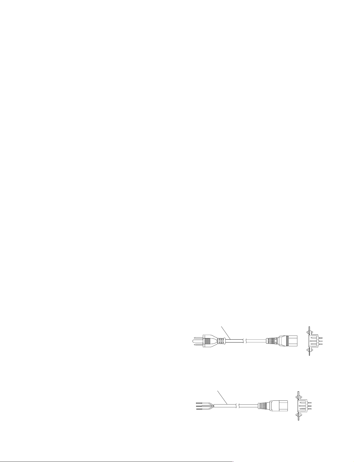
For customers in the U.S.A. and Canada
1 Power cord, 125 V 10 A (2.4 m) : ! 1-557-377-11
AC inlet
1
Section 1
Installation
1-1. Operating Environment (Common)
Operating guaranteed temperature : +5 dC to +40 dC
Performance guaranteed temperature : +10 dC to +35 dC
Operating humidity : 10 % to 90 %
Storage temperature : _20 dC to +60 dC
Mass
MKS-9011A : Approx. 10.0 kg
MKS-9012A : Approx. 11.5 kg
MKS-8011A : Approx. 2.3 kg
MKS-8031ATB : Approx. 0.7 kg
MKS-8032A : Approx. 0.7 kg
MKS-8033A : Approx. 0.7 kg
MKS-8035A : Approx. 0.6 kg
MKS-8041 : Approx. 0.4 kg
MKS-8075A : Approx. 0.6 kg
Prohibited locations for installation
. Areas where the unit will be exposed to direct sunlight or
any other strong lights.
. Dusty areas
. Areas subject to vibration.
. Areas with strong electric or magnetic fields.
. Areas near heat sources.
. Areas where is subject to electrical noise.
. Areas subject to static electricity.
Ventilation
The inside of the MKS-9011A/9012A is cooled by a fan.
The power supply can be damaged if the exhaust vent (on
the rear) and air intake (on the front) are blocked or the fan
is stopped.
Therefore, leave a blank space of more than 10 cm in the
front and back of the MKS-9011A/9012A.
n
As the inrush current at turn-on is a maximum 21.5 A (at
100 V) /52 A (at 240 V), the capacity of the AC power
source must be commensurate with this load.
If the capacity of the AC power is not adequately large, the
AC power source breaker will operate or the unit will
abnormally operate.
Recommended power cord
This unit does not come with a power cord.
To get a power cord, please contact your local Sony Sales
Office/Service Center.
w
. Use the approved Power Cord (3-core mains lead)/
Appliance Connector/Plug with earthing-contacts that
conforms to the safety regulations of each country if
applicable.
. Use the Power Cord (3-core mains lead)/Appliance
Connector/Plug conforming to the proper ratings (Voltage, Ampere).
If you have questions on the use of the above Power Cord/
Appliance Connector/Plug, please contact your local Sony
Sales Office/Service Center.
w
. Never use an injured power cord.
. Plugging the power cord in the AC inlet, push as far as it
will go.
1-2. Power Supply
Power specifications
A switching regulator is used for the power supply of
MKS-9011A/9012A. A voltage within the range of 100 V
to 240 V can be used without changing the supply voltage.
Power requirements: AC 100 to 240 V ± 10 %
Power frequency: 50/60 Hz
Current consumption
MKS-9011A: 1.0 - 0.6 A
MKS-9012A: 1.0 - 0.6 A
CCP-9000A
For customers in the all European countries
1 Power cord, 250 V 10 A (2.4 m) : ! 1-782-929-22
1
AC inlet
1-1
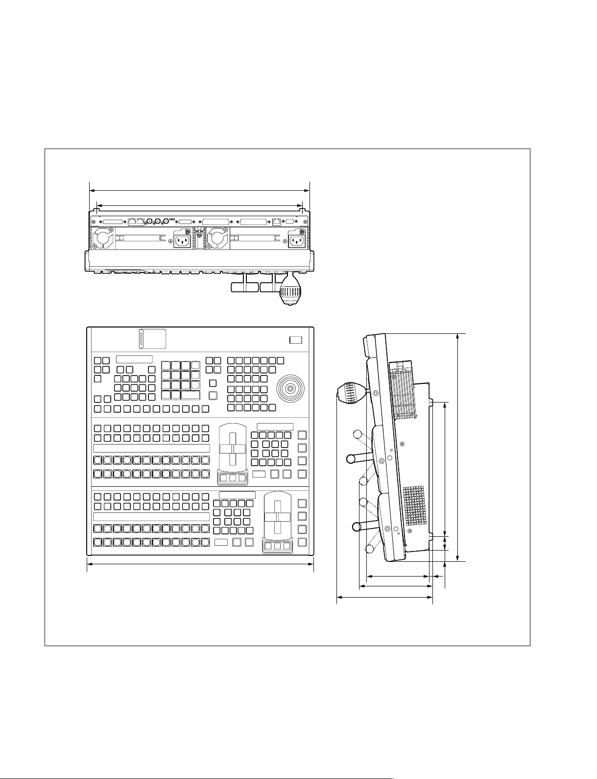
1-3. Installation Space
1-3-1. External Dimensions
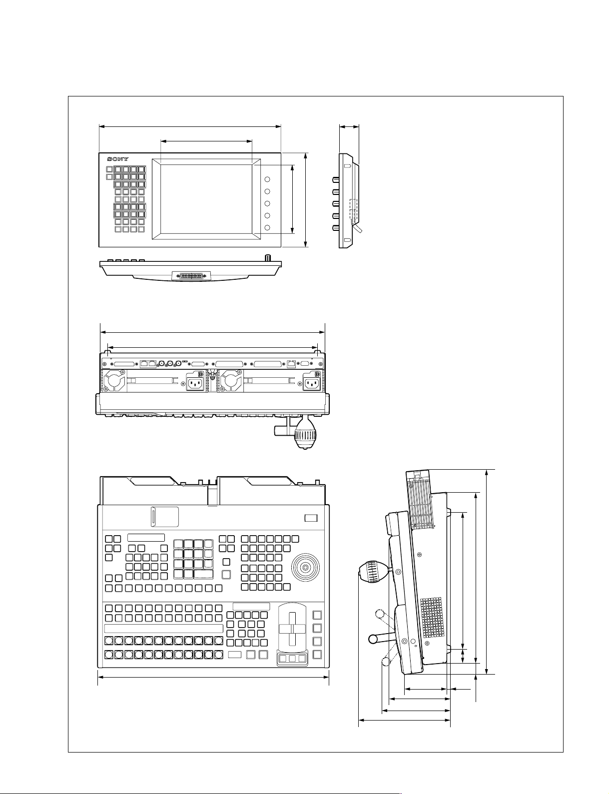
Center control panel MKS-9012A
428
384
1-2
440
119.4
142.6
186.6 (4U + 9)
260
26
7
442 (10U)
18.2
Unit : mm
CCP-9000A
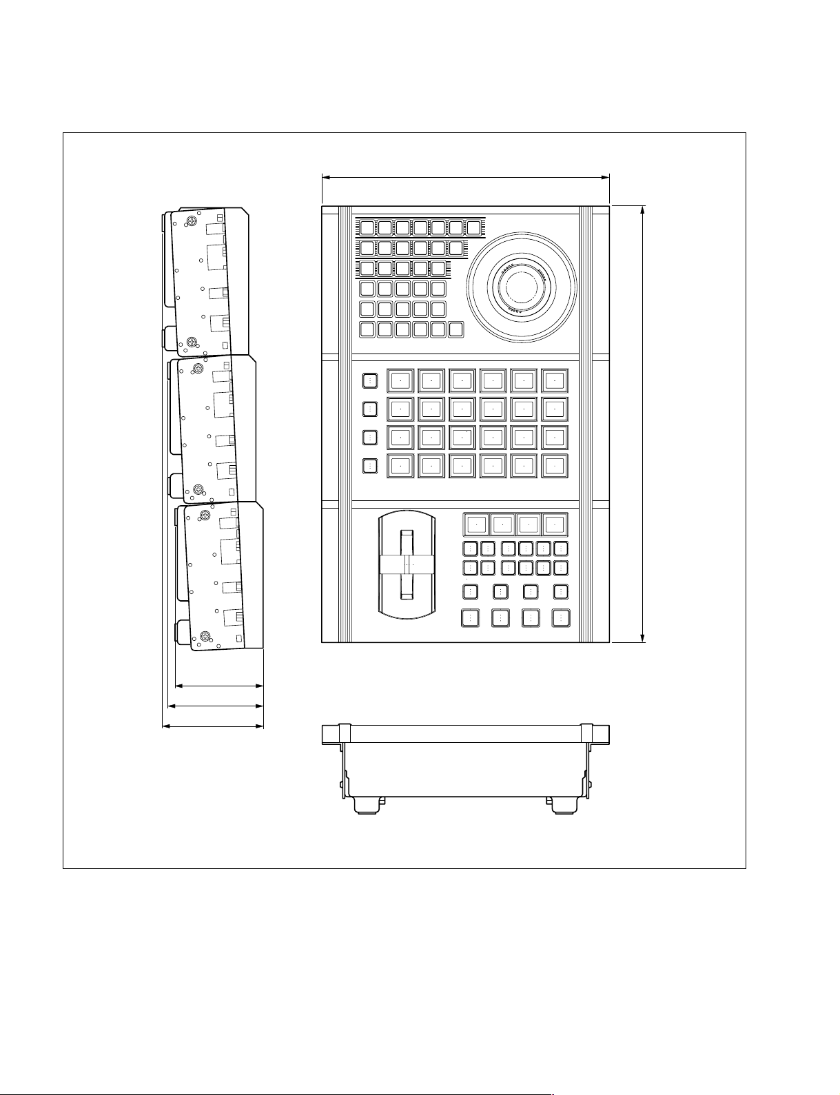
Center control panel MKS-9011A/Menu panel MKS-8011A
MKS-8011A
424
213
220
160
MKS-9011A
428
384
46
CCP-9000A
440
115.3
131
175 (4U)
80.8 7
260
26
324.2
385.3 (9U)
18.2
Unit : mm
1-3
Extension adaptor MKS-8075A
BANK
1
BANK
2
BANK
3
BANK
4
DSK3
DSK4
DSK3
ONONON
DSK2
ON
DSK1
DSK1
DSK4
DSK2
K-SS
STORE
TAKE TAKE TAKE TAKE
WIPE
MIX
DME
CUT
K-SS
SHIFT
UNDO
263
396
79
85
91
Unit : mm
1-4
CCP-9000A
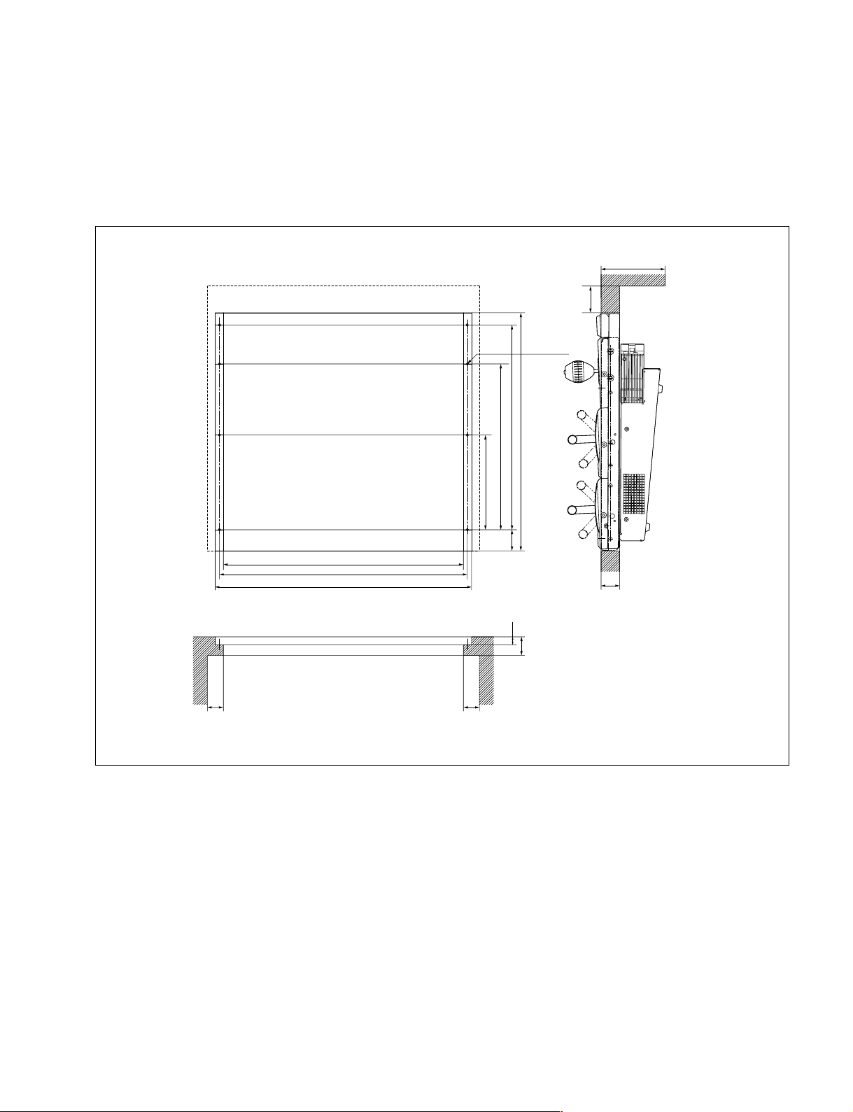
1-3-2. Installation Space
When the control panel is recessed into a control console or similar, make holes as shown below into the
control console with the following dimensions.
Center control panel MKS-9012A
120 or more
50 or more
6-M5
311.2
446.7
384.1
177.8
39.4
450
465
481
30 or more 30 or more
35
15
35
Unit : mm
CCP-9000A
1-5
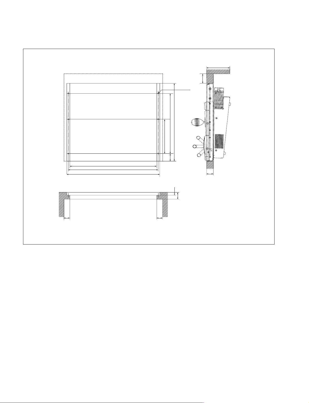
Center control panel MKS-9011A
120 or more
50 or more
6-M5
311.2
402.7
177.8
450
465
481
30 or more 30 or more
39.4
35
15
35
Unit : mm
1-6
CCP-9000A
 Loading...