

Page 1

SLOW SHUTTER BOARD
HKDW-705
INSTALLATION MANUAL
1st Edition
Page 2

! W ARNING
This manual is intended for qualified service personnel only.
To reduce the risk of electric shock, fire or injury, do not perform any servicing other than that
contained in the operating instructions unless you are qualified to do so. Refer all servicing to
qualified service personnel.
! W ARNUNG
Die Anleitung ist nur für qualifiziertes Fachpersonal bestimmt.
Alle Wartungsarbeiten dürfen nur von qualifiziertem Fachpersonal ausgeführt werden. Um die
Gefahr eines elektrischen Schlages, Feuergefahr und Verletzungen zu vermeiden, sind bei
Wartungsarbeiten strikt die Angaben in der Anleitung zu befolgen. Andere als die angegeben
Wartungsarbeiten dürfen nur von Personen ausgeführt werden, die eine spezielle Befähigung
dazu besitzen.
! AVERTISSEMENT
Ce manual est destiné uniquement aux personnes compétentes en charge de l’entretien. Afin
de réduire les risques de décharge électrique, d’incendie ou de blessure n’effectuer que les
réparations indiquées dans le mode d’emploi à moins d’être qualifié pour en effectuer d’autres .
Pour toute réparation faire appel à une personne compétente uniquement.
HKDW-705
Page 3

Section 1
Installation
1-1. HKDW-705 Configuration
The HKDW-705 consists of the following:
. PM-22 board (1)
. Precision screw P1.4 x 3.5 (2)
. Installation Guide (1)
. Installation Manual (1)
In addition to the Installation Manual, the following manuals are available.
. HDW-750/750P/730 Operation Manual (Supplied with HDW-750/750P/730)
This manual is necessary for application and operaion of HDW-750.
Part number: 3-205-316-1X
. HDW-750/750P/750CE/730, HKDW-702/703/705 Maintenance Manual Volume 1
(Available upon request)
This manual intended for use by trained system and service engineers describes (the circuit overview,
character display functions, the main part replacements, electrical alignment, etc.) required for partslevel service.
For obtaining, contact your local Sony Sales Office/Service Center.
Part number: 9-968-591-0X
. HDW-750/750P/750CE/730, HKDW-702/703/705 Maintenance Manual Volume 2
(Available upon request)
This manual is intended for use by trained system and service engineers, and describes the information
regarding the parts list, semiconductor pin assignments, block diagrams, schematic diagrams and board
layouts.
For obtaining, contact your local Sony Sales Office/Service Center.
Part number: 9-968-582-0X
1-2. Note When Installing the HKDW-705
1-2-1. Models to Which the HKDW-705 Can Be Installed
List of the HDW-750/730 models to which the HKDW-705 can be installed is shown below.
Models Serial No.
HDW-750 S/N 20001 and higher
S/N 80001 and higher
HDW-750P S/N 40001 and higher
HDW-730 S/N 10001 and higher
1-2-2. Using the HKDW-705 Together with the HKDW-702
When the HD-SD Down converter board HKDW-702 is already installed in the HDW-750/730, be sure to
check name of the board beforehand.
Some products of the HKDW-702 cannot be used together with the HKDW-705 depending on the time of
manufacture of the HKDW-702.
DC-110A board: It can be used together with the HKDW-705.
DC-110 board: It cannot be used together with the HKDW-705.
If DC-110 board is installed, it must be removed.
HKDW-705
1-1 (E)
Page 4
1-3. Installation Procedure
Outline of the installing the HKDW-705 to the HDW-750/730 is listed as follows. For the details of the
installation work, refer to the respective sections.
Installation procedure Sections describing the detailed procedure
1. Confirming the AT ROM Version 1-4. Confirming the AT ROM Version
2. Opening the Inside Panel 1-5. Opening and Closing the Inside Panel
3. Installing the HKDW-705 (PM-22 Board) 1-6. Installing the HKDW-705 (PM-22 Board)
4. Closing the Inside Panel 1-5. Opening and Closing the Inside Panel
5. Operation Check 1-7. Operating Procedure of the SLS Mode
Push the SHUTTER switch and confirm
that “ ** FRAME ” is displayed.
6. Adjusting after Installing 1-8. Adjustment after Installing the HKDW-705 (PM-22 Board)
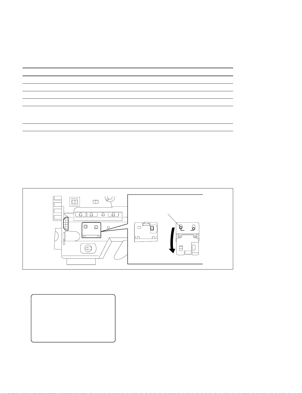
1-4. Confirming the AT ROM Version
Installation of the HKDW-705 requires that the ROM (IC38) on the AT-143 board of the HDW-750/730
is version 1.7 or higher. Confirm the ROM version before starting installation as follows.
1. Turn on the power of the HDW-750/730.
2. While pressing the rotary encoder, turn on the MENU ON/OFF switch to open the top menu.
MENU ON/OFF
switch
CANCEL/PRST
STATUS
ON/SEL
OFF
OFF
ESCAPE
ON
MENU
3. Select the DIAGNOSIS menu and press the rotary encoder.
4. Rotate the rotary encoder until the ROM VERSION display appears.
5. Confirm that the version display of AT is 1.7 or higher.
? 03OROM VERSION
AT : Ver 1.7
SS : Ver x.xx
FP : Ver x.xx
EQ : Ver x.xx
n
If the version display of AT is earlier than 1.7, upgrade of the ROM is required. Refer to “1-24.
Upgrading the ROM Version” in the Maintenance Manual Volume 1 of the HDW-750/750P/750CE/730,
HKDW-702/703/705.
1-2 (E)
HKDW-705
Page 5
1-5. Opening and Closing the Inside
Panel
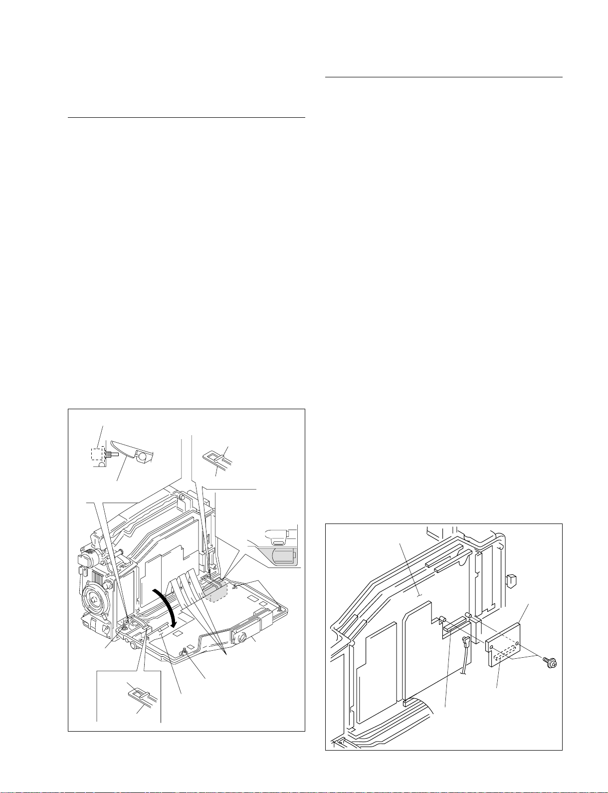
Opening the Inside Panel
m
. Be sure to set the POWER switch to OFF, unplug the
power cord or remove the battery before starting any of
the following procedure to protect inside of the unit from
damage.
. Insert a piece of paper between the hinge and the
connector box to prevent connector box from damaging
as it contacts with hinge.
1. Loosen the four screws (with drop-safe) and open the
inside panel assembly in the direction of the arrow.
m
. The flexible card wire that is connected to the FP-
121 board, will be significantly shortened its life if
it is folded. Be very careful not to fold the flexible
card wire.
. Stand the unit in the posture that the POWER
switch side faces upward when the inside panel
assembly is opened.
Closing the Inside Panel
1. Check that the hinges in the right and left are engaged
securely with the hooks of the chassis.
2. Insert the inside panel assembly and tighten the four
screws (with drop-safe).
n
Standard tightening torque value :
Screw (with drop-safe, B3 x 12)
80 x 10-2 N.m (8.0 kgf.cm)
n
Be careful not to pinch the harness between the inside
panel and chassis.
1-6. Installing the HKDW-705 (PM-22
Board)
n
When the DC-110 board is installed in the HDW-750/730,
it cannot be used together with the HKDW-705. (For
detail, refer to Section 1-2-2.)
When the DC-110 board is installed, remove it.
POWER switch
Inside panel
assembly
Screw
(with drop-safe)
Hook
Hinge
Hinge
Flexible
card wires
Screw (with drop-safe)
FP-121 board
Hook
Insert a piece of paper
into the protection block.
(Only when the connector
box is installed.)
Screws
(with drop-safe)
Inside panel
assembly
1. Insert the connector (CN1) of the PM-22 board to the
connector (CN7) of the DCP-28B board.
2. Attach the PM-22 board with the two precision screws
(P1.4 x 3.5) supplied.
n
Standard tightening torque value :
Screw P1.4 x 3.5
0.1 N.m (1.0 kgf.cm)
DCP-28B board
PM-22 board
Precision
screws
P1.4 x 3.5
CN1
CN7
HKDW-705
1-3 (E)
Page 6
1-7. Operating Procedure of the SLS
Mode
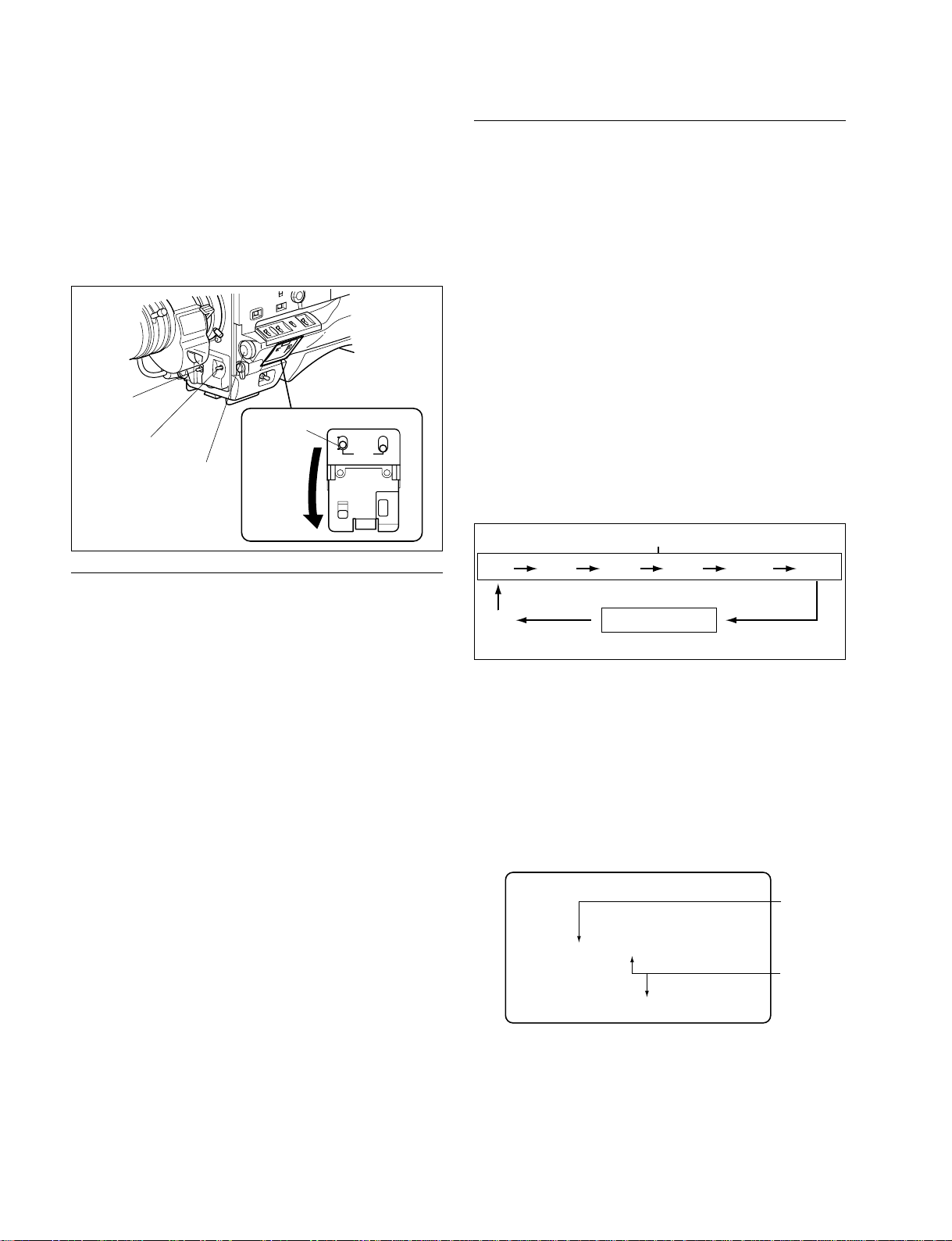
When the HKDW-705 is installed, the SLS (storage) mode
is added to the shutter mode.
The storage time can be selected and set in the SLS mode.
Either one of the 11 frames of 1F, 2F, 3F, 4F, 5F, 6F, 7F,
8F, 16F, 32F or 64F can be selected as the storage time.
SHUTTER
switch
AUTO W/B BAL
switch
Rotary
encoder
Notes
MENU ON/OFF
switch
OFF
ON ESCAPE
CANCEL/PRST
MENU
Operating Procedure
1. Set the MENU ON/OFF switch to ON.
2. Rotate the rotary encoder to select the VF DISP 1
display of the OPERATION menu and press the rotary
encoder.
3. Rotate the rotary encoder to set the “ VF DISPLAY
MODE” to either 2 or 3 and press the rotary encoder.
4. Set the MENU ON/OFF switch to OFF.
5. When the SHUTTER switch is pressed from the ON
position toward the SEL side, the present shutter
setting is displayed.
6. The colon “ : ” at the left end of the display turns on
for about 1 second. When the SHUTTER switch is
pressed toward the SEL side before the colon “ : ” is
turned off, the display changes in the following order.
7. Repeat pressing the SHUTTER switch until “ : SLS :
**FRAME” appears. (Number of frames in the range
of 1F to 64F appears in the place of **.)
Standard mode
1/100 1/125 1/250 1/500 1/1000 1/2000
When the SLS mode is used, the following limitations will
be set on the items below.
. AUTO IRIS :The AUTO IRIS is set to the OPEN position
forcibly. When user wants to adjust the iris
value, use the MANUAL setting mode.
. FLARE compensation :
The “ FLARE” item of the SW STATUS
display of the PAINT menu is set to OFF
forcibly.
. AWB : The longer the storage time is, the longer the
white balance automatic adjustment time
becomes.
The following phenomena are the characteristics of CCD
when setting the SLS mode, and do not indicate that the
CCD is defective. For details, please contact your local
Sony Sales Office/Service center.
. When number of frames of the SLS mode is increased,
the bright dots may become visible.
. When the operating mode is changed to the SLS mode
from the standard mode, there can be a change that
picture loses synchronization.
. When the OUTPUT/DCC switch is set from BARS →
CAM, there can be a change that picture loses
synchronization. (Only for the HDW-730 in the 50i
format mode, or the HDW-750P.)
. When number of frames of the SLS mode is increased
under the high temperature operating environment, there
can be a chance that flicker occurs on display.
1-4 (E)
ECS
mode
8.
When the rotary encoder is rotated while the colon “ : ”
: SLS : ** FRAME
SLS mode
is being displayed, the display changed to show the
number of frames. Set the desired number of frames.
n
Set the number of frames while the colon “ : ” is
being displayed.
When the colon “ : ” disappears, the number of frames
at that time will be set.
Example of the display setting to the SLS mode 8 FRAME
Turns on
:SLS:8 FRAME
Number
changes
1B W:A 0dB 8F C
n
The number of frames will be kept maintained even
after the power of the HDW-750/730 is turned off
when it is once set.
HKDW-705
Page 7
1-8. Adjustment after Installing the
—BLACK SET— —BLACK BAL——CHECK—
—MOD BAL— —BLACK SET——CHECK—
HKDW-705 (PM-22 Board)
When the HKDW-705 is installed, the automatic
adjustment must be executed.
n
The automatic adjustment take about 2 hours. Prepare the
power supply that can support the HDW-750/730 for more
than 2 hours.
1. Check that the SHUTTER switch is set to OFF.
2. Open the inside panel and set the switch S1-1 and S1-2
on the AT-143 board to ON.
3. Turn on the power.
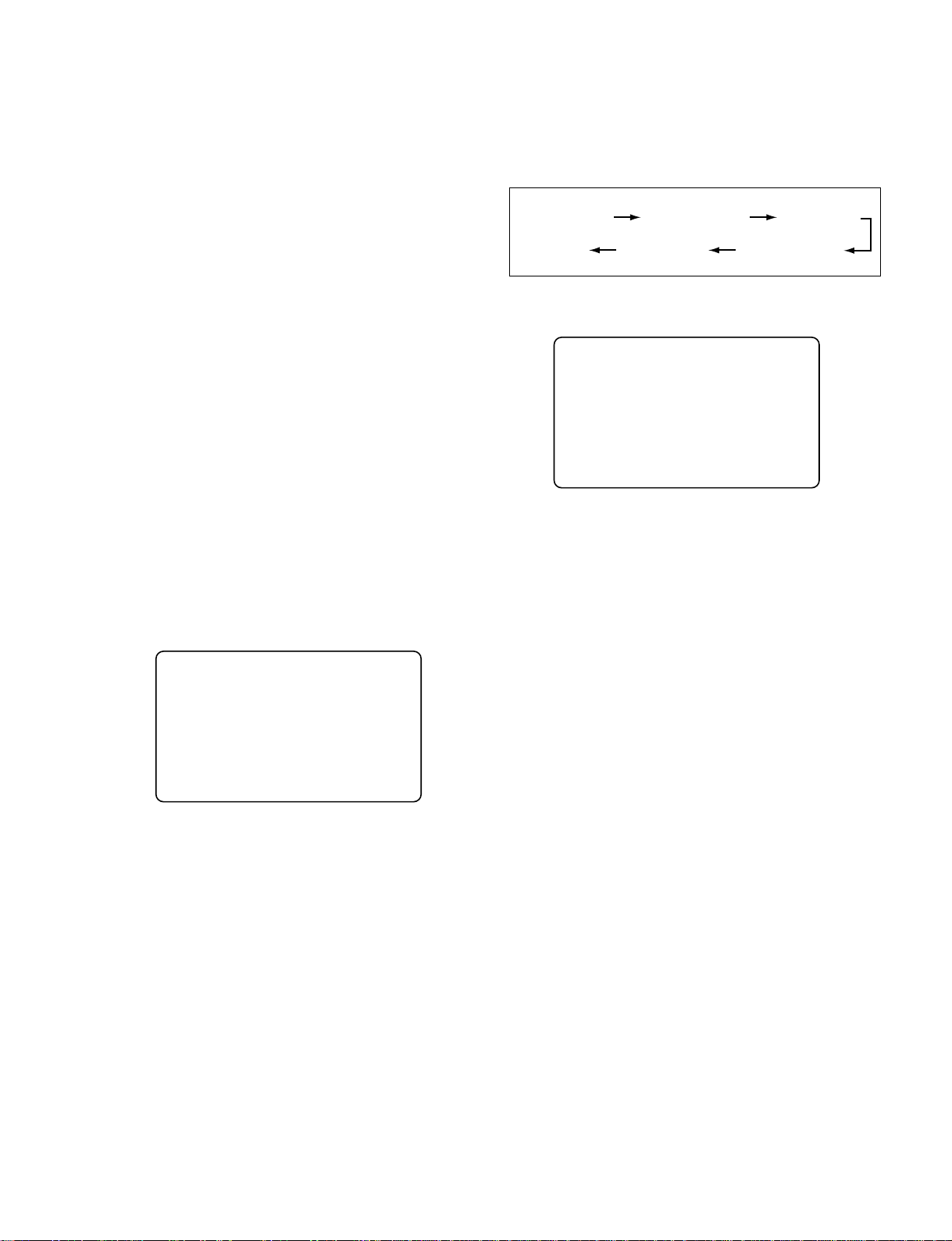
4. When the MENU ON/OFF switch is set to ON,
indication on display changes in the following order.
10. When the AUTO W/B BAL switch is kept pressed
toward the BLK side, the indication on display
changes in the following order.
Keep pressing until “ BLACK SET ” appears for the
second time.
BLACK : OP
-BLACK SET-
1B W:A 0dB C
“ BCS INITIALIZE”
↓
“ NOW EXECUTING...”
↓
“ COMPLETE!”
5. Check that the message “ COMPLETE!” is displayed.
S <TOP MENU>
COMPLETE !
USER
USER MENU CUSTOMIZE
ALL
. OPERATION
. PAINT
. MAINTENANCE
. FILE
. DIAGNOSIS
SERVICE
6. Set the switch S1-2 only on the AT-143 board to OFF.
7. Set the MENU ON/OFF switch to OFF.
8. Wait for 1 hour under the normal temperature.
9. After more than 1 hour has elapsed, set the SHUTTER
switch to ON and repeat pressing the SHUTTER
switch until“ : SLS : 1 FRAME” appears. (Refer to
section 1-7, step5 to 6.)
n
If any number of frames other than“ 1 FRAME” is
displayed, rotate the rotary encoder to set“ 1 FRAME”.
11. When the message“ CHECK” appears for the second
time, the automatic adjustment starts.
n
This adjustment takes about 30 to 60 minutes. Be
careful not to turn off the main power during this
period.
If the power is turned off in its middle, repeat the
procedure starting from step 1.
12. Check that the automatic adjustment is complete and
the message“ CHECK” has disappeared on the
display.
13. Set the switch S1-1 on the AT-143 board to OFF.
HKDW-705
1-5 (E)
Page 8

Page 9

The material contained in this manual consists of
information that is the property of Sony Corporation.
Sony Corporation expressly prohibits the duplication of
any portion of this manual or the use thereof for any
purpose other than the operation or maintenance of the
equipment described in this manual without the express
written permission of Sony Corporation.
Le matériel contenu dans ce manuel consiste en
informations qui sont la propriété de Sony Corporation.
Sony Corporation interdit formellement la copie de
quelque partie que ce soit de ce manuel ou son emploi
pour tout autre but que des opérations ou entretiens de
l’équipement à moins d’une permission écrite de Sony
Corporation.
Das in dieser Anleitung enthaltene Material besteht aus
Informationen, die Eigentum der Sony Corporation sind.
Die Sony Corporation untersagt ausdrücklich die
Ver vielfältigung jeglicher Teile dieser Anleitung oder den
Gebrauch derselben für irgendeinen anderen Zweck als
die Bedienung oder Wartung der in dieser Anleitung
beschriebenen Ausrüstung ohne ausdrückliche
schriftliche Erlaubnis der Sony Corporation.
HKDW-705
Page 10

HKDW-705 (SY) J, E
3-791-035-01
Printed in Japan
Sony Corporation 2003. 4 16
B&P Company ©2003
 Loading...