

Page 1
HD CAMERA CONTROL UNIT
HDCU3300
SD ENCODER UNIT
HKCU1001
MULTI INTERFACE UNIT
HKCU1003
SDI OUTPUT EXPANSION UNIT
HKCU1005
電気製品は、安全のための注意事項を守らないと、
火災や人身事故になることがあります。
このオペレーションマニュアルには、事故を防ぐための重要な注意事項と製品
の取り扱いかたを示してあります。このオペレーションマニュアルをよくお読
みのうえ、製品を安全にお使いください。お読みになったあとは、いつでも見ら
れるところに必ず保管してください。
OPERATION MANUAL [Japanese/English]
1st Edition (Revised 3)
Page 2
日本語
安全のために
ソニー製品は安全に十分に配慮して設計されています。しかし、電気製品はまち
がった使い方をすると、火災や感電などにより死亡や大けがなど人身事故につな
がることがあり、危険です。
事故を防ぐために次のことを必ずお守りください。
安全のための注意事項を守る
4 〜 7 ページの注意事項をよくお読みください。
警告表示の意味
このオペレーションマニュアルお
よび製品では、次のような表示を
しています。表示の内容をよく理
解してから本文をお読みください。
オプション基板の装着について
危険を避けるために、オプション基板の装着はサービストレーニングを受けた技
術者、もしくはソニーのサービス担当者または営業担当者にご依頼ください。
定期点検を実施する
長期間安全に使用していただくために、定期点検を実施することをおすすめしま
す。点検の内容や費用については、ソニーのサービス担当者または営業担当者に
ご相談ください。
故障したら使用を中止する
ソニーのサービス担当者または営業担当者にご連絡ください。
万一、異常が起きたら
異常な音、におい、煙が出たら
m
a 電源を切る。
b 電源コードや接続コードを抜く。
c ソニーのサービス担当者または営業担当者に修理を依頼する。
この表示の注意事項を守らないと、
火災や感電などにより死亡や大け
がなど人身事故につながることが
あります。
この表示の注意事項を守らないと、
感電やその他の事故によりけがを
したり周辺の物品に損害を与えた
りすることがあります。
注意を促す記号
炎が出たら
m
a すぐに電源を切り、消火する。
2
行為を禁止する記号
行為を指示する記号
Page 3
目次
警告....................................................................................................................4
注意....................................................................................................................5
その他の安全上のご注意 ..........................................................................................7
概要...........................................................................................................................8
システム構成例.......................................................................................................10
基本構成機器...............................................................................................10
HD スーパーモーション /HD/SD 信号併用システム .................................11
使用上のご注意.......................................................................................................12
各部の名称と働き ...................................................................................................13
前面 .............................................................................................................13
後面 .............................................................................................................14
SD エンコーダーユニット HKCU1001(別売り)........................................17
マルチインターフェースユニット HKCU1003(別売り)............................17
SDI 出力拡張ユニット HKCU1005(別売り)..............................................19
内部スイッチと内部基板 ........................................................................................20
内部スイッチ...............................................................................................20
内部基板 ......................................................................................................20
仕様.........................................................................................................................24
HDCU3300...................................................................................................24
HKCU1001(別売り)..................................................................................25
HKCU1003(別売り)..................................................................................25
HKCU1005(別売り)..................................................................................26
JP
目次
3
Page 4
外装を外さない、改造しない
外装を外したり、改造したりすると、感
電の原因となります。
内部の調整や設定および点検を行う必要
がある場合は、必ずサービストレーニン
グを受けた技術者にご依頼ください。
内部に水や異物を入れない
水や異物が入ると火災や感電の原因とな
ります。
万一、水や異物が入ったときは、すぐに
電源を切り、電源コードや接続コードを
抜いて、ソニーのサービス担当者または
営業担当者にご相談ください。
油煙、湯気、湿気、ほこりの
多い場所では設置・使用しない
上記のような場所で設置・使用すると、
火災や感電の原因となります。
表示された電源電圧で使用す
る
機器に表示されたものと異なる電源電圧
で使用すると、火災や感電の原因となり
ます。
ラックの上部に設置しない
本機は重量があります。ラックの上部に
設置すると、ラックが転倒してけがの原
因となることがあります。ラックの下か
らの高さがおよそ 1m 以内の位置に設置
してください。
機器を固定する
地震などにより機器が転倒・落下する
と、大けがの原因となります。システム
マニュアルに従って機器をラックに固定
してください。
指定の電源コードを使用する
指定以外の電源コードを使用すると、火
災や感電の原因となります。
他の電源コードを使用する場合は、ソ
ニーのサービス担当者または営業担当者
にご相談ください。
電源コードを傷つけない
電源コードを傷つけると、火災や感電の
原因となります。
• 電源コードを加工したり、傷つけたり
しない。
• 重いものをのせたり、引っ張ったりし
ない。
• 熱器具に近づけたり、加熱したりしな
い。
• 電源コードを抜くときは、必ずプラグ
を持って抜く。
• ラックマウントするとき、レールには
さみ込まない。
万一、電源コードが傷んだら、ソニーの
サービス担当者に交換をご依頼ください。
ケーブルを傷つけたまま使用
しない
ケーブルを傷つけたまま使用すると、火
災や感電の原因となります。
光ファイバーケーブルは定期
的に交換する
光ファイバーケーブルは、劣化したまま
使用すると火災や感電の原因となりま
す。
定期的にケーブルを交換してください。
電源コードのプラグおよびコ
ネクターは突き当たるまで差
し込む
まっすぐに突き当たるまで差し込まない
と、火災や感電の原因となります。
4
警告
Page 5
密閉環境には設置しない
空調管理されていない密閉環境に設置す
ると、内部に熱がこもり、火災の原因と
なることがあります。
正しいインターフェースで接
続する
RCP/CNU 端子、WFREMOTE 端子、
MICREMOTE 端子、I/OPORT 端子、
WFMODE 端子、および Ethernet 端子
に外部機器を接続する場合、接続時のイ
ンターフェースが正しくないと火災や感
電の原因となります。これらの端子への
機器の接続はサービストレーニングを受
けた技術者にご依頼ください。
安定した姿勢でラックマウン
トする
本機をラックマウントするとき、および
取り外すとき、バランスを崩すと機器が
落下してけがの原因となることがありま
す。安定した姿勢で注意深く作業してく
ださい。
ラックは転倒・移動防止の処
理をする
地震などによりラックが転倒・移動する
と大けがの原因となります。また、ラッ
クの設置状況、強度を充分にお確かめく
ださい。
安全アースを接続する
安全アースを接続しないと、感電の原因
となることがあります。次の方法でアー
スを接続してください。
• 電源コンセントが 3 極の場合
指定の電源コードを使用することで安
全アースが接続されます。
• 電源コンセントが 2 極の場合
指定の 3 極 t2 極変換プラグを使用
し、変換プラグから出ている緑色の
アース線を建物に備えられているアー
ス端子に接続してください。
変換プラグ
アース線
安全アースを取り付けることができない
場合は、ソニーのサービス担当者にご連
絡ください。
注意
5
Page 6
指定の接続ケーブルを使用す
る
指定されたラックマウント
レールを使用する
光ファイバーケーブルは、指定のケーブ
ルメーカーに加工をご依頼ください。指
定どおりのものを使用しないと、火災や
感電の原因となります。
指定以外の機器を接続しない
本マニュアルに記載している以外の機器
を接続すると、火災や感電の原因となり
ます。(詳しくは 10 〜 11 ページを参照)
ラックマウントレールに手や
指をはさまない
ラックマウントした機器を収納するとき
および引き出すとき、ラックマウント
レールに手や指をはさみ、けがの原因と
なることがあります。
通風孔をふさがない
通風孔をふさぐと内部に熱がこもり、火
災の原因となることがあります。
• 逆さまや横倒しにしない。
• 風通しの悪い、狭いところに押し込ま
ない。
• 毛足の長いじゅうたんや布団の上に置
かない。
• 布をかけない。
指定以外のラックマウントレールを使用
すると、レールの強度不足により、機器
が落下してけがの原因となることがあり
ます。
2 人以上でラックマウント・
運搬する
本機は重量があり、かつ左右のバランス
が悪いので、けがや事故を防ぐため、
ラックマウントや運搬は必ず 2 人以上で
行ってください。
2 台以上積み上げない
ラックを使用せずに 2 台以上積み上げる
と、製品が落下してけがの原因となるこ
とがあります。
6
注意
Page 7

その他の安全上のご注意
レーザー機器についてのご注意
ここに規定した以外の手順による制御および調整は、危険
なレーザー放射の被爆をもたらします。
ご注意
日本国内で使用する電源コードセットは、電気用品安全
法で定める基準を満足した承認品が要求されます。ソ
ニー推奨の電源コードセットをご使用ください。
7
Page 8

概要
SDI 出力拡張ユニット HKCU1005
HD-SDI または SD-SDI 信号の出力端子を 4 つ持っていま
す。
HD スーパーモーションカメラコントロールユニット
HDCU3300 は、ソニーの HD スーパーモーションカラーカ
メラ HDC3300 と接続し、信号処理と外部機器とのイン
ターフェースを行う装置です。
本機は、HD 信号1)をSD信号2)に変換するダウンコン
バーターと、SD 信号を HD 信号に変換するリターンビデオ
簡易アップコンバーターを標準装備し、ハイデフィニショ
ンスーパースローモーションカメラシステムはもとより現
行カメラシステムとしても運用可能です。
1)HD 信号(HighDefinition):1125/750 ラインの HDTV 信号の総称
2)SD 信号(StandardDefinition):NTSC/PAL 信号、525/625 コンポーネン
ト信号、525/625 コンポジット信号の総称
本機は、別売りのマスターセットアップユニット MSU-900
シリーズまたはリモートコントロールパネル RCP-700/900
シリーズを組み合わせて、カメラコントロールシステムを
構成します。また、カメラコマンドネットワークユニット
CNU-700 を使って、複数のビデオカメラをコントロールす
るシステムを構成することもできます。
本機の主な特長は次のとおりです。
外部同期信号
本機を外部からの同期信号にロックさせることができます。
外部同期信号には、HD3 値シンク、または SD 信号のシン
ク(ブラックバースト)を使用します。
ダウンコンバーター内蔵
システムをフィールド周波数 59.94/50Hz に設定していると
きに、HD 信号をダウンコンバーターで SD コンポーネント
SDI 信号に変換し出力できます。出力信号のアスペクト比
は 4:3 エッジクロップ、16:9 スクイーズ、レターボックス
の設定が可能です。またダウンコンバーターには、イメー
ジエンハンサー、ガンマコントロール、マトリックス ON/
OFF 機能があり、外部からのコントロールが可能です。
簡易アップコンバーター内蔵
SD 信号のリターンビデオを HD ビューファインダーでモニ
ターするために簡易アップコンバーターを装備しています。
リターンビデオのアスペクト比は 4:3 エッジクロップ、16:9
スクイーズ、レターボックスの設定が可能です。
光デジタル伝送
多系統ビデオ入出力
HDCU3300 は、それぞれ次のような信号の入出力端子を標
準装備しています。
• HD-SDI 出力(SS-A/B/C)各2系統
• HD-SDI 出力 4 系統
• SDI 出力 4 系統(HD/SD 切り換え可能)
• HD-SDI リターン入力 4 系統
• SD-SDI リターン入力 4 系統
• SD アナログリターン入力 4 系統
• プロンプター入力 2 系統
さらに、各種のオプション基板を装着することによって、
次のような信号の入出力が可能になります。
SD エンコーダーユニット HKCU1001、マルチインター
フェースユニット HKCU1003
この基板を装着することによって、SD アナログコンポジッ
ト信号(NTSC/PAL)、SD ピクチャーモニター信号、SD
波形モニター信号の出力が可能になります。
ご注意
HKCU1003 に同梱の VDA-C 基板は使用できません。
光ファイバーケーブル(シングルモード光ファイバー線 2
本、電源線 2 本、制御線 2 本)でカメラと本機を接続し、
デジタル化したビデオ、音声、制御信号を伝送します。長
さ 500m の光ファイバーケーブルの多段接続により、2,500
m の信号伝送が可能になります(カメラへの給電のケーブ
ル長は、カメラシステムの構成、光ファイバーケーブルの
種類で異なります)。
安全性を考慮した電源部
電源投入時には、まず低電圧の電源を送って所定のカメラ
が接続されていることを確認した後、正規の AC240V を供
給する安全設計になっています。光電気複合ケーブルを介
してカメラが接続されていないときは電源を供給しません。
また、ケーブルのオープン、ショートを知らせるアラーム
インジケーターを装備しています。
ご注意
HDC1000/1500 シリーズのカメラを接続しないでください。
HDC1000/1500 シリーズのカメラを接続した場合、カメラ
へ電源を供給しますが、信号のインターフェースが異なる
ため通信できません。また、カメラの映像信号も出力でき
ません。
概要
8
Page 9

豊富なオーディオ機能
2 チャンネルのマイク出力、デジタルオーディオ出力、お
よびプログラムオーディオ用入力端子を装備しています。
さらに、独立した 2 チャンネルのインターカムシステムが
使用可能で、4 線または RTS/ クリアカムインターカムシ
ステムに対応できるようになっています。
◆ RTS/ クリアカムシステムへの対応については、ソニーのサー
ビス担当者または営業担当者にお問い合わせください。
各種信号のリモートコントロール
本機が出力する各種信号のレベルや位相を、マスターセッ
トアップユニット MSU-900 シリーズからコントロールする
ことができます。
マイク音量レベルのコントロール
MICREMOTE 端子から、カメラのマイク音量レベルをコ
ントロールすることができます。
キャラクターモニター信号出力
本機の自己診断の状態や設定メニューを文字表示として
キャラクター付きの信号を出力することができます。
ラックマウント可能
本機は 19 インチの EIA 規格標準ラックに組み込むことが
できます。高さは 3 ユニットです。
プラグイン方式のユニット構成
内蔵のプリント基板は簡単に抜き差しできる構成のため、
保守・点検が容易です。
概要
9
Page 10
システム構成例
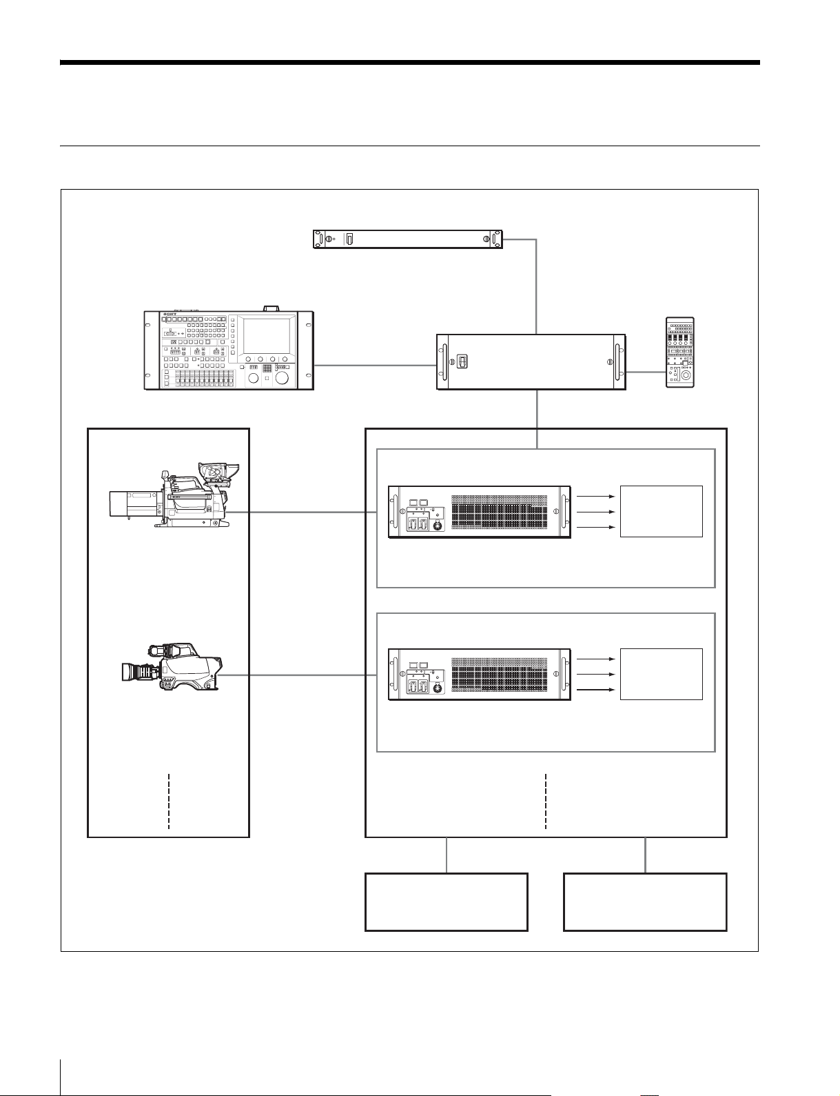
基本構成機器
SD ビデオセレクター VCS-700
マスターセットアップユニット MSU-900 シリーズ
カメラ 1
HD カラーカメラ HDC3300
+ 大型レンズアダプター
HDLA1500
+HD エレクトロニックビュー
ファインダー HDVF-9900
カメラ 2
HD カラーカメラ
HDC3300
+
HD エレクトロニックビュー
ファインダー HDVF-20A
光ファイバー
ケーブル
光ファイバー
ケーブル
カメラコントロールユニット 1
HD カメラコントロールユニット
HDCU3300
カメラコントロールユニット 2
HD カメラコントロールユニット
HDCU3300
リモートコントロールパネル
RCP-700/900 シリーズ
カメラコマンドネットワーク
ユニット CNU-700
SS-A
SS-B
SS-C
SS-A
SS-B
SS-C
HD ビデオ
サーバー
HD ビデオ
サーバー
10
システム構成例
プログラム音声
インターカムシステム
Page 11
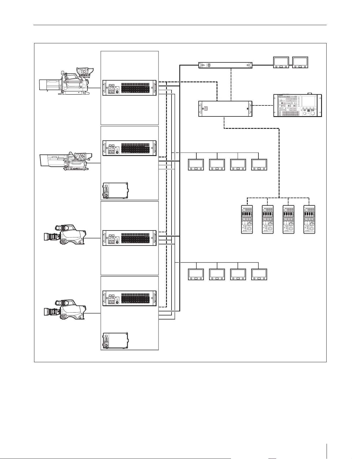
HD スーパーモーション /HD/SD 信号併用システム
HDC3300+HDLA1500
HDC1000
HDC3300
HDCU3300
(+HKCU1001/HKCU1003)
HDCU1000
(+HKCU1001/HKCU1003)
または
HDCU1500
(+HKCU1001/HKCU1003)
HDCU3300
(+HKCU1001/HKCU1003)
PIX/WF
SD-SDI
VCS-700
MSU-900 シリーズ
CNU-700
HDC1500
RCP シリーズ
HD-SDI
HDCU1000
(+HKCU1001/HKCU1003)
または
HDCU1500
(+HKCU1001/HKCU1003)
システム構成例
11
Page 12

使用上のご注意
設置環境
• 高温の部屋や熱源の近くは避けること。
• 強電界や強磁界の場所に置かないこと。
• 乾燥した通風の良い場所であること。
• 太陽光線、強力ライトなどが直接あたる場所は避けるこ
と。
12
使用上のご注意
Page 13
各部の名称と働き
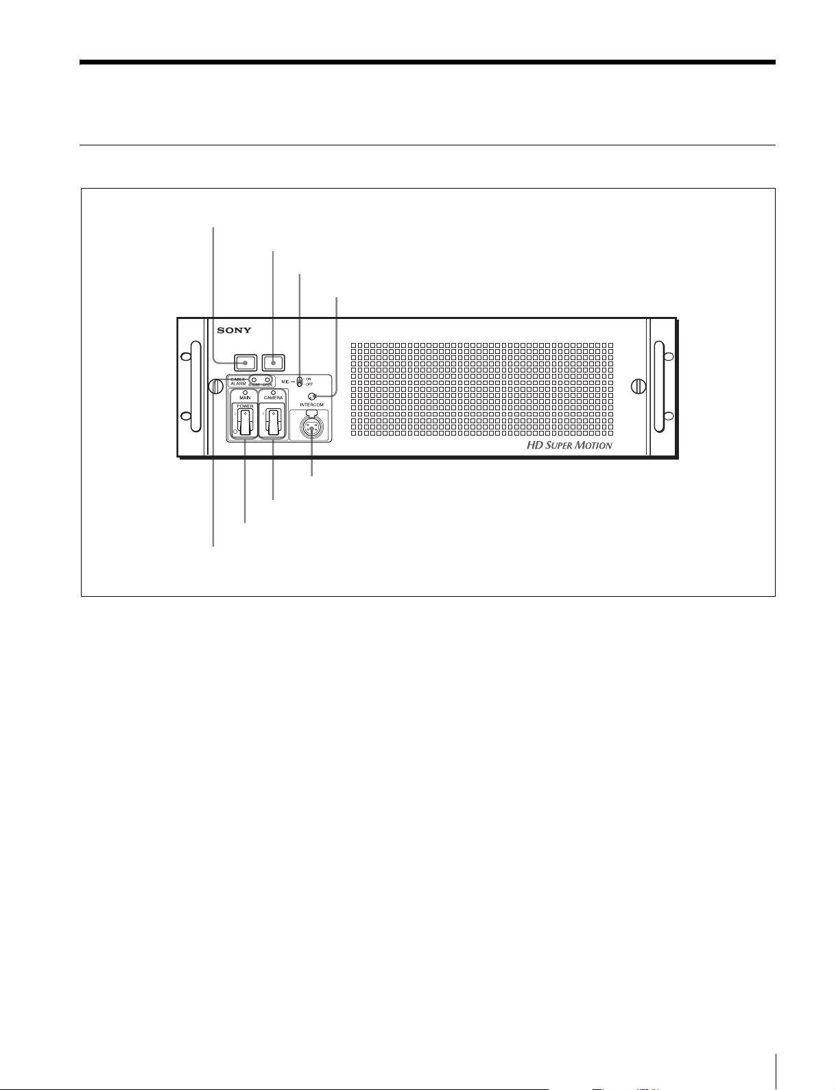
前面
1 レッドタリーランプ
2 グリーンタリーランプ
1
7 CAMERA スイッチとインジケーター
6 MAINPOWER スイッチとインジケーター
3 MIC スイッチ
4 INTERCOM つまみ
HD CAMERA CONTROL UNIT HDCU3300
8 INTERCOM 端子
5 CABLEALARM インジケーター
a レッドタリーランプ
レッドタリー信号を受信したときに点灯します。また、ビ
デオカメラ、マスターセットアップユニット MSU-900 シ
リーズ、リモートコントロールパネル RCP-700/900 シリー
ズなどで CALL ボタンが押されると、ランプが点灯してい
たときは消灯し、消灯していたときは点灯します。付属の
ナンバープレートをここに取り付けることができます。
b グリーンタリーランプ
グリーンタリー信号を受信したときに点灯します。付属の
ナンバープレートをここに取り付けることができます。
c MIC(マイク)スイッチ
ヘッドセットのマイク入力を ON/OFF するときに使いま
す。
d INTERCOM(インターカム音量調節)つまみ
インターカムの受信レベルを調整します。
e CABLEALARM(ケーブルアラーム)インジケーター
SHORT(赤):光ファイバーケーブルの電源供給線が外部
シースにショートしているか、または 2 本の電源供給
線がショートしているときに点灯します。点灯中はカ
メラへは電源が供給されません。
OPEN(赤):後面の CAMERA 端子に光ファイバーケー
ブルを介してカメラが接続されていないとき点灯しま
す。光ファイバーケーブルの光受信状態が悪い場合は
点滅して警告表示します。
f MAINPOWER(主電源)スイッチとインジケーター
本機、ビデオカメラ、および本機の REMOTE 端子に接続
したリモートコントロールパネル RCP-700/900 シリーズな
ど、本システム全体の電源を入 / 切します。「?」側を押す
と電源が入り、「a」側を押すと電源が切れます。電源が入
るとインジケーターが点灯します。
各部の名称と働き
13
Page 14
g CAMERA(カメラ電源)スイッチとインジケーター
MAINPOWER スイッチが「?」側になっているとき、この
スイッチでビデオカメラの電源を入 / 切します。「?」側を
押すと電源が入り、「1」側を押すと電源が切れます。電源
が入るとインジケーターが点灯します。
リモートコントロールパネルが接続されている場合に、リ
モートコントロールパネルの CAMPW ボタンで給電が
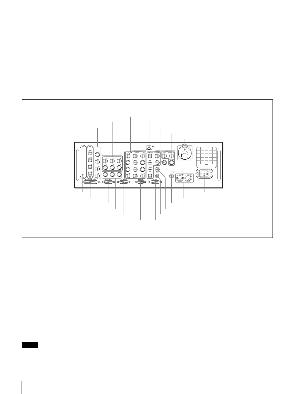
後面
OFF されていると、本スイッチだけではビデオカメラの電
源を入れることはできません。
h INTERCOM(インターカム)端子(XLR5 ピン)
ヘッドセットを接続します。
◆ XLR5 ピン以外のプラグの付いたヘッドセットをお使いになる
ときは、ソニーのサービス担当者または営業担当者にお問い合
わせください。
4 RETURNINPUT 部
3SUPERMOTIONOUTPUT 部
2HDSDIOUTPUT 部
1 SDIOUT 部
SLOT2
SLOT3
HD SDI
SDI OUT
OUTPUT
SLOT1
SUPER MOTION OUTPUT
CAB
0 拡張スロット
qa INTERCOM/TALLY/PGM 端子
qs MICREMOTE 端子
7 スペア端子
qd WFREMOTE 端子
qf TRUNKLINE 端子
a SDIOUT(SDI 出力端子)部(BNC 型)
ビデオカメラからの信号を HD-SDI 信号または SD-SDI 信
号として 2 系統出力します。
SDIOUT3 端子と SDIOUT4 端子からは、キャラクターや
マーカーを重畳した信号を出力できます。
SD-SDI 信号を出力するには、システムがフィールド周波数
59.94/50Hz で動作している必要があります。
◆ 設定方法については、ソニーのサービス担当者または営業担当
者にお問い合わせください。
b HDSDIOUTPUT(HDSDI 出力)部(BNC 型)
ビデオカメラからの標準速映像を HD-SDI 信号として4系
統出力します。
5 Ethernet 端子
6 INPUT 部
7 スペア端子
8 OUTPUT 部
9 CAMERA 端子
w; 〜 ACIN 端子
ql MIC1、MIC2 端子
qk TRUNKA 端子
qj RCP/CNU 端子
qh WFMODE 端子
qg I/OPORT 端子
設定メニューで、電源が ON の間もカラーバーを出力でき
るようにすることができます。この場合、カメラのビュー
ファイダーにもカラーバーが出力されます。
◆ 設定メニューの操作については、ソニーのサービス担当者また
は営業担当者にお問い合わせください。
c SUPERMOTIONOUTPUT(スーパーモーション出
力)部(BNC 型)
ビデオカメラからの HD スーパースローモーション映像を
LINK-A、LINK-B、LINK-C として、それぞれ 2 系統出力
します。各 LINK の下段の端子はスペア端子です。
ご注意
この出力端子からは、ビデオカメラの電源が ON の間はカ
ラーバーを出力することはできません(初期設定)。本機の
各部の名称と働き
14
Page 15

d RETURNINPUT(リターンビデオ入力端子)部
ご注意
1 HD-SDI1 〜 4(HD-SDI リターンビデオ 1、2、3、4
入力)端子(BNC 型)
4 系統の HD-SDI リターンビデオ信号を個別に入力するこ
とができます。RET1 〜 RET4 の選択は、カメラ側のリ
ターンスイッチで行います。
RET1、2、3、4 の各系統に接続する信号は、本機の設定
メニューまたはマスターセットアップユニット MSU-900 シ
リーズで選択することができます。
◆ 設定メニューについては、ソニーのサービス担当者または営業
担当者にお問い合わせください。
◆ マスターセットアップユニットのマニュアルも併せてご覧くだ
さい。
2 SD-SDI1〜 4(SD コンポーネント SDI リターンビデオ
1、2、3、4 入力)端子(BNC 型)
フィールド周波数 59.94/50Hz でシステムが動作している
ときに、4 系統の SD コンポーネント SDI リターンビデオ
信号を個別に入力することができます。
RET1 〜 RET4 の選択はカメラ側のリターンスイッチで行
います。RET1、2、3、4 の各系統に接続する信号は、本
機の設定メニューまたはマスターセットアップユニット
MSU-900 シリーズで選択することができます。また、SD
信号では、アスペクト比も選択可能です。
◆ 設定メニューの操作については、ソニーのサービス担当者また
は営業担当者にお問い合わせください。
◆ マスターセットアップユニットのマニュアルも併せてご覧くだ
さい。
3 VBS1 〜 4(VBS リターンビデオ 1、2、3、4 入力)
端子(BNC 型)
4 系統の VBS リターンビデオ信号を個別に入力することが
できます。
RET1 〜 RET4 の選択はカメラ側のリターンスイッチで行
います。RET1、2、3、4 の各系統に接続する信号は、本
機の設定メニューまたはマスターセットアップユニット
MSU-900 シリーズで選択することができます。また、SD
信号では、アスペクト比も選択可能です。
◆ 設定メニューの操作については、ソニーのサービス担当者また
は営業担当者にお問い合わせください。
◆ マスターセットアップユニットのマニュアルも併せてご覧くだ
さい。
e Ethernet(イーサネット)端子(RJ-458 ピン)
将来の拡張用です。
安全のために、周辺機器を接続する際は、過大電圧を持つ
可能性があるコネクターをこの端子に接続しないでくださ
い。
f INPUT(入力端子)部
1 PROMPTER1、2(プロンプター入力 1、2)端子
(BNC 型)
いずれか一方の端子にテレプロンプター用信号を入力しま
す。もう一方の端子からは、入力された信号がそのまま出
力(ループスルー)されます。ループスルー出力を使用し
ない場合は、75Ω で終端してください。
信号は、1.0Vp-p、75Ω のアナログ信号であれば、信号規
格を問わず周波数帯域 5MHz でビデオカメラの
PROMPTEROUT 端子から出力することができます。
2 REFERENCE(リファレンス入力)端子(BNC 型)
いずれか一方の端子に外部同期用の HD3 値基準同期信号ま
たは SD 基準同期信号(ブラックバースト信号)を入力し
ます。
もう一方の端子からは、入力された信号がそのまま出力
(ループスルー)されます。ループスルー出力を使用しない
場合は、75Ω で終端してください。
リファレンス信号の種類は、本機の設定メニューまたはマ
スターセットアップユニット MSU-900 シリーズで選択しま
す。
◆ 設定メニューについては、ソニーのサービス担当者または営業
担当者にお問い合わせください。
◆ マスターセットアップユニットのマニュアルも併せてご覧くだ
さい。
ご注意
SD エンコーダーユニット HKCU1001 やマルチインター
フェースユニット HKCU1003 の VBS 信号を使用する場合
(SC 位相ロックが必要な場合)は、SD 基準同期信号(ブ
ラックバースト信号)を入力してください。
g スペア端子(BNC 型)
将来の拡張用です。
h OUTPUT(出力端子)部
1 SYNC(同期信号出力)端子(BNC 型)
内部の同期信号発生器からの SD コンポジットシンク信号
(バースト信号なし)または HD3 値同期信号が出力されま
す。(工場設定 :SD コンポジットシンク信号)
◆ 信号の選択方法については、ソニーのサービス担当者または営
業担当者にお問い合わせください。
各部の名称と働き
15
Page 16

2 CHARACTER(キャラクター出力)端子(BNC 型)
本機の自己診断結果や設定メニューを SD アナログビデオ
信号として出力します。
コール式波形モニターでは、表示モードを波形モニターで
設定(プリセット)し、そのモードを外部から選択(リ
コール)します。
3 AES/EBU 端子(BNC 型)
ビデオカメラに入力された AES/EBU フォーマットのデジ
タルオーディオ信号を出力します。
i CAMERA(カメラ)端子(光ファイバーコネクター)
光ファイバーケーブルでビデオカメラと接続します。電源、
コントロール信号、ビデオ信号、音声信号など、ビデオカ
メラのすべての信号を光ファイバーケーブル 1 本で送受信
することができます。
ご注意
光ファイバーケーブルの接続端面にほこりなどが付着する
と、伝送エラーが発生しますので、接続しないときは、必
ず付属のキャップをはめてください。
j 拡張スロット
別売りの SD エンコーダーユニット HKCU1001、マルチイ
ンターフェースユニット HKCU1003 または SDI 出力拡張
ユニット HKCU1005 を取り付けます。
◆ 取り付けについては、ソニーのサービス担当者または営業担当
者にお問い合わせください。
k INTERCOM/TALLY/PGM(インターカム / タリー/ プ
ログラムオーディオ)端子(D-sub25 ピン)
インターカム、タリー、プログラムオーディオの各信号を
入出力します。インターカムシステムのインターカム / タ
リー / プログラムオーディオ端子と接続します。
◆ 操作については、マスターセットアップユニットまたはリモー
トコントロールパネルのマニュアルをご覧ください。
n TRUNKLINE(トランクライン)端子(D-sub9 ピン、
RS-232C 準拠)
カメラの CCU 用通信端子と RS-232C でインターフェース
するための端子です。主にカメラ側で用いる機器との通信
回線用として使用します。最大 2 チャンネルの通信が可能
です。
o I/OPORT(I/O ポート)端子(D-sub15 ピン)
外部コントロール機器とのリモートコントロール用です。
ご注意
幅 42mm 以上の D-sub ケースを使用すると、245 の端
子が干渉します。JAE 製 DA-C1-J10 の使用をお勧めしま
す。
p WFMODE(波形モニターモード出力)端子(4 ピン)
波形モニターを使って、シーケンシャルモードで信号をモ
ニターするとき、波形モニターの対応する端子と接続しま
す。
リモートコントロールパネル RCP-700/900 シリーズまたは
マスターセットアップユニット MSU-900 シリーズの SEQ
ボタンを押すと、シーケンス信号が出力され、R、G、B 信
号をシーケンシャルモードで、3 波形同時にモニターする
ことができます。(RCP と MSU を同時使用している場合
は、RCP コントロール用の出力端子となります。)
l MICREMOTE(マイクリモート)端子(D-sub15 ピ
ン)
オーディオミキサーなどの外部コントロール機器から、こ
のコネクターを介して、ビデオカメラのマイク入力レベル
を 5 段階(− 60/ − 50/ − 40/ − 30/ − 20dB)に設定す
ることができます。撮影時の音量条件によって適正なレベ
ルに設定してください。
また、この端子からもレッドタリー、グリーンタリー信号
を出力できます。
◆ マイク入力レベルは、設定メニューで設定することもできます。
設定メニューについては、ソニーのサービス担当者または営業
担当者にお問い合わせください。
m WFREMOTE(波形モニターリモート)端子(D-sub
15 ピン)
波形モニターの表示をマスターセットアップユニット
MSU-900 シリーズまたはリモートコントロールパネル
RCP-700/900 シリーズでリモートコントロールするとき、
リコール式波形モニターの対応する端子と接続します。リ
◆ 操作については、マスターセットアップユニットまたはリモー
トコントロールパネルのマニュアルをご覧ください。
q RCP/CNU 端子(8 ピン)
接続ケーブル CCA-5 を使って、マスターセットアップユ
ニット MSU-900 シリーズまたはカメラコマンドネットワー
クユニット CNU-700、リモートコントロールパネル RCP700/900 シリーズを接続します。この端子を介して、コン
トロール信号を送受信します。RCP-700/900 シリーズを接
続したときは、電源も供給します。
r TRUNKA(トランク A)端子(丸型 12 ピン)
カメラの CCU 用通信端子と RS-232C または RS-422A でイ
ンターフェースするための端子です。2 チャンネルの通信
が可能です。
s MIC1、MIC2(マイク出力 1、2)端子(XLR3 ピン)
ビデオカメラに入力されたマイク信号を出力します。
16
各部の名称と働き
Page 17

t 〜 ACIN(AC 電源入力)端子
指定の電源コードで AC 電源に接続します。別売りのプラ
グホルダーで電源コードを本機に固定することができます。
SD エンコーダーユニット HKCU1001(別売り)
VDA-A 基板
VDA-A
VBS
1
2
1 VBS1、2 端子
ご注意
危険を避けるために、機器内部の操作は、サービストレー
ニングを受けた技術者が行ってください。
SD エンコーダーユニット HKCU1001 は、EN-A(フロン
ト)基板と VDA-A(リア)基板で構成されます。
本機の前後の拡張スロットに EN-A 基板と VDA-A 基板を
取り付けると、VDA-A 基板コネクターから、SD コンポ
ジット信号、波形モニター出力信号、ピクチャーモニター
出力信号を出力できます。
◆ 取り付けについては、ソニーのサービス担当者または営業担当
者にお問い合わせください。
EN-A 基板
EN-A
NTSC
1 SD 信号フォーマットインジケーター
PAL
PIX
OUT
2 PIXOUT 端子
WF
OUT
3 WFOUT 端子
a VBS1、2(コンポジットビデオ信号出力 1、2)端子
(BNC 型)
ビデオカメラからの信号を、アナログコンポジットビデオ
信号で 2 系統出力します。
b PIXOUT(ピクチャーモニター出力)端子(BNC 型)
リモートコントロールパネル RCP-700/900 シリーズまたは
マスターセットアップユニット MSU-900 シリーズの
PICTUREMONITOR ボタンで選択した、ピクチャーモニ
ター用ビデオ信号が出力されます。
また、キャラクターやマーカー信号が重畳できます。
◆ 操作については、マスターセットアップユニットまたはリモー
トコントロールパネルのマニュアルをご覧ください。
SC PHASE
ADV
2 SCPHASE スイッチ
DELAY
a SD 信号フォーマットインジケーター
SD 信号のフォーマットに対応して点灯します。
b SCPHASE(サブキャリア位相)スイッチ
SD 基準同期信号(ブラックバースト信号)に対する SC 位
相を調整します。
ADV 側に押すと位相が進み、DELAY 側に押すと位相が遅
れます。
モメンタリースイッチで、押している間だけ位相が変化し
ます。
c WFOUT(波形モニター出力)端子(BNC 型)
リモートコントロールパネル RCP-700/900 シリーズまたは
マスターセットアップユニット MSU-900 シリーズの WF
MONITOR ボタンで選択した波形モニター用ビデオ信号が
出力されます。
◆ 操作については、マスターセットアップユニットまたはリモー
トコントロールパネルのマニュアルをご覧ください。
マルチインターフェースユニット HKCU1003(別売り)
ご注意
危険を避けるために、機器内部の操作は、サービストレー
ニングを受けた技術者が行ってください。
マルチインターフェースユニット HKCU1003 は、EN-B
(フロント)基板と 3 タイプの VDA(リア)基板(A/B/
C)で構成されます。現在 HDCU3300 では、VDA-A 基板
のみ実質的に有効で、HDCU1001 と同等の動作をします。
各部の名称と働き
17
Page 18

ご注意
VDA-B 基板も使用できますが、FRAMEREFIN 端子は機
能しません。
◆ 取り付けについては、ソニーのサービス担当者または営業担当
者にお問い合わせください。
EN-B 基板
EN-B
NTSC
1 SD 信号フォーマットインジケーター
PAL
REF IN
2 SUB-REF インジケーター
UN
LOCK
SC PHASE
ADV
3 SCPHASE スイッチ
DELAY
a SD 信号フォーマットインジケーター
SD 信号のフォーマットに対応して点灯します。
VDA-A 基板
VDA-A
VBS
1
1 VBS1、2 端子
2
PIX
OUT
2 PIXOUT 端子
WF
OUT
3 WFOUT 端子
a VBS1、2(コンポジットビデオ信号出力 1、2)端子
(BNC 型)
ビデオカメラからの信号を、アナログコンポジットビデオ
信号で 2 系統出力します。
b PIXOUT(ピクチャーモニター出力)端子(BNC 型)
リモートコントロールパネル RCP-700/900 シリーズまたは
マスターセットアップユニット MSU-900 シリーズの
PICTUREMONITOR ボタンで選択した、ピクチャーモニ
ター用ビデオ信号が出力されます。
また、キャラクターやマーカー信号が重畳できます。
b SUB-REF(サブリファレンス)インジケーター
VDA-B 基板を使用中、VDA-B 基板の FRAMEREFIN 端
子に入力された同期信号に対応して点灯します。
REF-IN:VDA-B 基板の FRAMEREFIN 端子に適切な同
期信号が入力されたときに点灯します。
UNLOCK:本機の設定と入力された同期信号の種類が一
致しないときなどに点灯します。
c SCPHASE(サブキャリア位相)スイッチ
SD 基準同期信号(ブラックバースト信号)に対する SC 位
相を調整します。
ADV 側に押すと位相が進み、DELAY 側に押すと位相が遅
れます。
モメンタリースイッチで、押している間だけ位相が変化し
ます。
◆ 操作については、マスターセットアップユニットまたはリモー
トコントロールパネルのマニュアルをご覧ください。
c WFOUT(波形モニター出力)端子(BNC 型)
リモートコントロールパネル RCP-700/900 シリーズまたは
マスターセットアップユニット MSU-900 シリーズの WF
MONITOR ボタンで選択した波形モニター用ビデオ信号が
出力されます。
◆ 操作については、マスターセットアップユニットまたはリモー
トコントロールパネルのマニュアルをご覧ください。
18
各部の名称と働き
Page 19

VDA-B 基板
VDA-B
FRAME
REF IN
1 FRAMEREFIN、OUT 端子
OUT
PIX
OUT
2 PIXOUT 端子
WF
OUT
3 WFOUT 端子
a FRAMEREFIN、OUT(フレームリファレンス入力、
出力)端子(BNC 型)
現在は使用できません。
b PIXOUT(ピクチャーモニター出力)端子(BNC 型)
リモートコントロールパネル RCP-700/900 シリーズまたは
マスターセットアップユニット MSU-900 シリーズの
PICTUREMONITOR ボタンで選択した、ピクチャーモニ
ター用ビデオ信号が出力されます。
◆ 操作については、マスターセットアップユニットまたはリモー
トコントロールパネルのマニュアルをご覧ください。
DRX 基板
DRX
1080
720P
SD
PsF
FC
1 出力信号フォーマットインジケーター
60
50
30
25
24
a 出力信号フォーマットインジケーター
出力信号フォーマットのステータスを表示します。
1080/720P/SD:本機から出力される 4 系統の SDI 信
号のうち、1、2 系統に出力される信号の状態を表示し
ます。
PsF:現在は機能しません。
FC:本機のフレームレートコンバーター機能が働いている
とき点灯します。
60/50/30/25/24:出力信号のフィールド / フレーム周
波数に応じて点灯します。
c WFOUT(波形モニター出力)端子(BNC 型)
リモートコントロールパネル RCP-700/900 シリーズまたは
マスターセットアップユニット MSU-900 シリーズの WF
MONITOR ボタンで選択した波形モニター用ビデオ信号が
出力されます。
◆ 操作については、マスターセットアップユニットまたはリモー
トコントロールパネルのマニュアルをご覧ください。
SDI 出力拡張ユニット HKCU1005
(別売り)
ご注意
危険を避けるために、機器内部の操作は、サービストレー
ニングを受けた技術者が行ってください。
SDI 出力拡張ユニット HKCU1005 は、DRX(フロント)基
板と HIF(リア)基板で構成されます。
本機前後の拡張スロットに DRX 基板と HIF 基板を取り付
けると、SDI 出力端子を 4 系統増設することができます。
◆ 取り付けについては、ソニーのサービス担当者または営業担当
者にお問い合わせください。
ご注意
本機では 30/25/24 は機能しません。
HIF 基板
SDI OUT
1
2
1 SDIOUT1、2、3、4 端子
3
4
a SDIOUT1、2、3、4(HD/SD シリアルデジタルイ
ンターフェース出力 1 〜 4)端子(BNC 型)
ビデオカメラから HD-SDI 信号または SD-SDI 信号を 4 系
統出力します。
各部の名称と働き
19
Page 20

内部スイッチと内部基板
危険を避けるために、機器内部の操作は、サービストレー
ニングを受けた技術者が行ってください。
内部スイッチ
下記の内部スイッチは、フロントパネルを開いたセット内
側にあります。
CARBON:カーボンマイク(電源供給、ゲイン 20dB)
ECM:コンデンサーマイク(電源供給、ゲイン 40dB)
DYNAMIC:ダイナミックマイク(電源非供給、ゲイン 60
dB)
d ヘッドセットマイク設定スイッチ 2(S5)
ヘッドセットマイク設定スイッチ 1(S4)を DYNAMIC に
設定したときは、さらにヘッドセットマイクの出力に合わ
せてこのスイッチを設定します。
ON:不平衡型
OFF:平衡型
内部基板
2 プログラムオーディオミックス
設定スイッチ(S3)
1 インターカム選択スイッチ(S2)
S3S2
PGM ON
CABLE
ALARM
POWER
MAIN
SHORT OPEN
1
CAMERA
ON
MIC
OFF
INTERCOM
S4
PRODPRIVENGCARBONECMDYNAMIC
PGM OFF
S5
O N
OFF
3 ヘッドセットマイク設定スイッチ 1(S4)
4 ヘッドセットマイク設定スイッチ 2(S5)
a インターカム選択スイッチ(S2)
本機前面の INTERCOM 端子で入出力される信号の接続先
を選択します。
PROD:プロデューサーラインに接続されます。
PRIV:プロデューサーライン、エンジニアラインとの接続
が切断され、本機とカメラ間の通話のみ可能になりま
す。
ENG:エンジニアラインに接続されます。
b プログラムオーディオミックス設定スイッチ(S3)
ヘッドセットのインカムにプログラムオーディオをミック
スするかどうかを選択します。
c ヘッドセットマイク設定スイッチ 1(S4)
本機前面の INTERCOM 端子に接続するヘッドセットのマ
イクに合わせて設定します。
AT 基板
AT
1 ACCESS インジケーター
2「メモリースティック」スロット
REFERENCE
H PHASE
a ACCESS(アクセス)インジケーター
「メモリースティック」の状態を表示します。
表示 意味/対応
消灯 「メモリースティック」が挿入されていません。
緑色に点灯 「メモリースティック」が挿入されています。
赤色に点灯 データの読み出し / 書き込み中です。この状態
b「メモリースティック」スロット
本機のソフトウェアのバージョンアップ用「メモリース
ティック」を挿入します。
「メモリースティック」の入れかた
「メモリースティック」のラベル側を手前にしてスロットに
差し込みます。
「メモリースティック」が正しくセットされると、ACCESS
インジケーターが緑に点灯します。インジケーターが点灯
3 Ethernet インジケーター
REF IN
UN
4 REFERENCE インジケーターとスイッチ
LOCK
HD
RMT
SD
ADV
5 HPHASE スイッチ
DELAY
で「メモリースティック」を抜き差しすると
データは保障されません。全データが消えてし
まうこともあります。
内部スイッチと内部基板
20
Page 21

しない場合は、「メモリースティック」の向きが逆になって
いる可能性があります。確認して正しく入れ直してくださ
い。取り出すときは、「メモリースティック」を押してくだ
さい。
a CCUPOWER(電源)インジケーター
本機の電源電圧が正常なとき点灯します。
b CAMLOCK(カメラロック)インジケーター
カメラとの通信が正常に行われているときに点灯します。
ご注意
ACCESS インジケーターが赤く点灯しているとき(データ
の読み出し / 書き込み中)は、「メモリースティック」を取
り出さないでください。データが消えてしまうことがあり
ます。
c Ethernet(イーサネット)インジケーター
将来の拡張用です。
d REFERENCE(リファレンス)インジケーターとス
イッチ
本機の REFERENCE 端子に接続する同期信号の種類をス
イッチで選択します。
HD:HD3 値基準同期信号(ローカル設定)
RMT(リモート):マスターセットアップユニット MSU-
900 シリーズで選択した信号
SD:SD 基準同期信号(ブラックバースト信号)(ローカ
ル設定)
REFERENCE 端子に信号が入力されると REFIN インジ
ケーターが点灯します。本機の設定と入力同期信号の種類
が一致しない場合などに UNLOCK インジケーターが点灯
します。
c CAMPOWER(カメラ電源)スイッチ
下側に押すと、本機と接続しているカメラの電源を ON/
OFF できます。
d SYSTEM(システム)インジケーター
/1.001(フレーム周波数):システムのフレーム周波数が
1/1.001 に設定されているときに点灯します。
LINEDELAY(位相差):HD 出力と SD 出力の位相差が
LINEDELAY に設定されている時に点灯します。
走査線数 1125 本の HD の場合は 90H、走査線数 720 本
の HD の場合は 120H の位相差になります。
e 2WIRECANCEL(2 線インターカムキャンセル)つま
み
2 線システム使用時に、それぞれプロデューサーライン
(PROD)およびエンジニアライン(ENG)のサイドトー
ンレベルが最小になるように調整します。
CPU 基板
e HPHASE(H 位相)スイッチ
H 位相を調整します。ADV 側に押すと位相が進み、
DELAY 側に押すと位相が遅れます。
モメンタリースイッチで、押している間だけ位相が変化し
ます。
AVP 基板
AVP
CCU
1 CCUPOWER インジケーター
POWER
CAM
2 CAMLOCK インジケーター
LOCK
CAM POWER
SYSTEM
2WIRE CANCEL
3 CAMPOWER スイッチ
ON/
OFF
/1.001
4 SYSTEM インジケーター
LINE
DELAY
PROD
5 2WIRECANCEL つまみ
ENG
CPU
1 ACCESS インジケーター
2 「メモリースティック」スロット
a ACCESS(アクセス)インジケーター
「メモリースティック」の状態を表示します。
表示 意味 / 対応
消灯 「メモリースティック」が挿入されていません。
緑色に点灯 「メモリースティック」が挿入されています。
赤色に点灯 データの読み出し / 書き込み中です。この状態
で「メモリースティック」を抜き差しすると
データは保障されません。全データが消えてし
まうこともあります。
内部スイッチと内部基板
21
Page 22

b「メモリースティック」スロット
本機のソフトウェアのバージョンアップ用「メモリース
ティック」を挿入します。
「メモリースティック」の入れかた
「メモリースティック」のラベル側を手前にしてスロットに
差し込みます。
「メモリースティック」が正しくセットされると、ACCESS
インジケーターが緑に点灯します。インジケーターが点灯
しない場合は、「メモリースティック」の向きが逆になって
いる可能性があります。確認して正しく入れ直してくださ
い。取り出すときは、「メモリースティック」を押してくだ
さい。
ご注意
ACCESS インジケーターが赤く点灯しているとき(データ
の読み出し / 書き込み中)は、「メモリースティック」を取
り出さないでください。データが消えてしまうことがあり
ます。
DISP:本機の設定状態を表示します。
OFF:設定状態やメニューなどのキャラクター表示を消し
ます。
MENU:設定メニューを表示します。
c CANCEL/ENTER(取り消し / 決定)スイッチ
メニュー画面の操作に使用します。ENTER 側に押すと設
定項目の選択や決定、CANCEL 側に押すと設定項目の選択
取り消しができます。
d + / −スイッチ
設定メニューの各項目の調整に使用します。
DPR-A 基板
DPR A
1080
720P
DTX 基板
DTX
CCU
1 光信号受信状態インジケーター
CAM
CHARACTER
DISP
OFF
2 メニュー操作スイッチ
MENU
CANCEL
3 CANCEL/ENTER スイッチ
ENTER
4 +/−スイッチ
a 光信号受信状態インジケーター
それぞれ本機側(CCU)とカメラ側(CAM)における光
信号の受信状態(受信レベル)を表示します。
緑:良好です。
黄:受信レベルが低下しています。
赤:受信レベルが著しく低下、もしくは受信が遮断されて
います。
本機とカメラ間の通信に異常が発生しているときは、CAM
インジケーターは緑黄赤すべて消灯します。
PsF
MODE
1 出力信号フォーマットインジケーター
60
50
30
25
24
a 出力信号フォーマットインジケーター
出力信号フォーマットのステータスを表示します。
1080/720P:本機から出力される 2 系統の HD-SDI 信号
(SS-A/B/C)の状態を表示します。
PsF:現在は機能しません。
MODE:将来の拡張用です。
60/50/30/25/24:出力信号のフィールド / フレーム周
波数に応じて点灯します。
ご注意
本機では 30/25/24 は機能しません。
b メニュー操作スイッチ
モニター出力に本機の設定状態を表示したり、設定メ
ニューの表示を行います。
内部スイッチと内部基板
22
Page 23

DPR-B 基板
FC:現在は機能しません。
60/50/30/25/24:出力信号のフィールド / フレーム周
波数に応じて点灯します。
ご注意
DPR B
1080
720P
PsF
1 出力信号フォーマットインジケーター
60
50
30
25
24
a 出力信号フォーマットインジケーター
出力信号フォーマットのステータスを表示します。
1080/720P:本機から出力される 4 系統の HD-SDI 信号
の状態を表示します。
PsF:現在は機能しません。
60/50/30/25/24:出力信号のフィールド / フレーム周
波数に応じて点灯します。
ご注意
本機では 30/25/24 は機能しません。
本機では 30/25/24 は機能しません。
DRX 基板
DRX
1080
720P
SD
PsF
FC
1 出力信号フォーマットインジケーター
60
50
30
25
24
a 出力信号フォーマットインジケーター
出力信号フォーマットのステータスを表示します。
1080/720P/SD:本機から出力される 4 系統の SDI 信
号のうち、1、2 系統に出力される信号の状態を表示し
ます。
PsF:現在は機能しません。
内部スイッチと内部基板
23
Page 24

仕様
HDCU3300
TRUNKA 12 ピン(1)
TRUNKLINE D-sub9 ピン、凹(1)、RS-232C、CHU 伝
送またはシステム拡張用
I/OPORT D-sub15 ピン、凹(1)
(推奨 JAE 製 DA-C1-J10)
Ethernet 6 ピン(1)
一般
電源 AC100/120/220-240V、50/60Hz
(各電圧への切り換えは、ソニーの
サービス担当者または営業担当者にお
問い合わせください。)
消費電流 最大 5.6A
動作温度 5 ℃〜 40 ℃
保存温度 − 20 ℃〜+ 60 ℃
質量 約 16.8kg
外形寸法図(単位:mm)
入力端子
ACIN (1)、AC100/110-120/220-240V(スイッ
チで切り換え)
HDSERIALRETINPUT
BNC 型(4)、SMPTE292M
ビットレート:1.485Gbps/1.4835Gbps
SDSERIALRETINPUT
BNC 型(4)、SMPTE259M
ビットレート:270Mbps
REFERENCEINPUT
BNC 型(2)、ループスルー出力
HD:SMPTE274M、3 値シンク、
0.6Vp-p、75Ω
SD:ブラックバースト
(NTSC:0.286Vp-p、75Ω/
PAL:0.3Vp-p、75Ω)
または NTSC10F-BB
PROMPTER1,2INPUT
410
MICREMOTE D-sub15 ピン(1)(推奨 JAE 製 DA-C1-
BNC 型(各 2)、ループスルー出力、アナ
ログ信号、1.0Vp-p、75Ω
J10)
424
465
481
入出力端子
CAMERA 光ファイバーコネクター(1)
10.692Gbps/10.681GbpsSDI × 2、
AC240V 給電
INTERCOM/TALLY/PGM
D-sub25 ピンコネクター(1)
• INTERCOM(PD/ENG)、4W/RTS/
CC、0dB
• PGM-2 系統、0dB/ − 20dB
• TALLY(R、G)
RCP/CNU 8 ピンマルチコネクター(1)
出力端子
MICOUT XLR3 ピン、凸(2)、0dBs/ − 20dBs
AES/EBU BNC 型(1)、AES/EBU フォーマット
52.7
133
CHARACTER BNC 型(1)、VBS、1Vp-p、75Ω、キャ
ラクターの ON/OFF 可能
WFREMOTE D-sub15 ピン、凹(1)
(推奨 JAE 製 DA-C1-J10)
SS-AOUT BNC 型(2)
HD-SDI:SMPTE292M、0.8Vp-p、
75Ω、1.485Gbps/1.4835Gbps
SS-BOUT BNC 型(2)
HD-SDI:SMPTE292M、0.8Vp-p、
75Ω、1.485Gbps/1.4835Gbps
SS-COUT BNC 型(2)
HD-SDI:SMPTE292M、0.8Vp-p、
75Ω、1.485Gbps/1.4835Gbps
HD-SDIOUT BNC 型(4)
HD-SDI:SMPTE292M、0.8Vp-p、
75Ω、1.485Gbps/1.4835Gbps
SDIOUT BNC 型(2)
24
仕様
Page 25

HD-SDI:SMPTE292M、0.8Vp-p、
75Ω、1.485Gbps/1.4835Gbps
SD-SDI:SMPTE259M、0.8Vp-p、75Ω、
270Mbps
HD-SDI/SD-SDI 切り換え可能
SDIOUT(MONI)
BNC 型(2)
HD-SDI:SMPTE292M、0.8Vp-p、
75Ω、1.485Gbps/1.4835Gbps
SD-SDI:SMPTE259M、0.8Vp-p、75Ω、
270Mbps
HD-SDI/SD-SDI 切り換え可能
SYNCOUT BNC 型(1)
HD:BTA-S001A、3 値シンク、0.6Vp-p、
75Ω
SD:コンポジットシンク、0.3Vp-p、
75Ω
HDSYNC/SDSYNC 切り換え可能
WFMODE 4 ピン(1)
付属品
ナンバープレート(1 式)
ヒューズ(1 式)
オペレーションマニュアル(1)
別売り品
電源コードセット(1-791-041-3X)
3極t2 極変換プラグ(1-793-461-12)
電源コード用プラグホルダー(3-613-640-01)
SD エンコーダーユニット HKCU1001
マルチインターフェースユニット HKCU1003
SDI 出力拡張ユニット HKCU1005
接続ケーブル CCA-5-3(3m)、CCA-5-10(10m)
延長基板
メンテナンスマニュアル
関連機器
HD カラーカメラ HDC1000/1500 シリーズ
HD カメラコントロールユニット HDCU1000/1500
リモートコントロールパネル RCP-700/900 シリーズ
マスターセットアップユニット MSU-900 シリーズ
ビデオセレクター VCS-700
カメラコマンドネットワークユニット CNU-700
マルチビットレートルーティングスイッチャー HDS-X3400
本機は「高調波電流規格 JIS61000-3-2 適合品」です。
この装置は、情報処理装置等電波障害自主規制協議会
(VCCI)の基準に基づくクラス A 情報技術装置です。こ
の装置を家庭環境で使用すると電波妨害を引き起こすこ
とがあります。この場合には使用者が適切な対策を講ず
るように要求されることがあります。
仕様および外観は、改良のため予告なく変更することがあ
りますが、ご了承ください。
HKCU1001(別売り)
一般
消費電力 2.5W
動作温度 − 10 ℃〜+ 40 ℃
保存温度 − 20 ℃〜+ 60 ℃
外形寸法(幅×高さ×奥行き)
EN-A 基板:約 19× 110 × 226mm
VDA-A 基板:約 19× 98× 159mm
質量 EN-A 基板:約 0.22kg
VDA-A 基板:約 0.10kg
出力端子
VDA-A 基板
VBS BNC 型(2)、1.0Vp-p、75Ω、VBS
PIXOUT BNC 型(1)、VBS/R/G/B
(VBS1.0Vp-p、75Ω)
WFOUT BNC 型(1)、VBS/R/G/B
(VBS1.0Vp-p、75Ω)
付属品
4 ピンコネクター(1)
この装置は、情報処理装置等電波障害自主規制協議会
(VCCI)の基準に基づくクラス A 情報技術装置です。こ
の装置を家庭環境で使用すると電波妨害を引き起こすこ
とがあります。この場合には使用者が適切な対策を講ず
るように要求されることがあります。
仕様および外観は、改良のため予告なく変更することがあ
りますが、ご了承ください。
HKCU1003(別売り)
一般
消費電力 3.6W
動作温度 − 10 ℃〜+ 40 ℃
保存温度 − 20 ℃〜+ 60 ℃
仕様
25
Page 26

外形寸法(幅×高さ×奥行き)
EN-B 基板:約 19× 110 × 226mm
VDA-A/B/C 基板:
約19×98×159mm
質量 EN-B 基板:約 0.22kg
VDA-A/B/C 基板:約 0.10kg
入出力端子
VDA-A 基板
VBS BNC 型(2)、1.0Vp-p、75Ω、VBS
PIXOUT BNC 型(1)、VBS/R/G/B
(VBS1.0Vp-p、75Ω)
WFOUT BNC 型(1)、VBS/R/G/B
(VBS1.0Vp-p、75Ω)
VDA-B 基板
FRAMEREFIN
BNC 型(1)
FRAMEREFOUT
BNC 型(1)
PIXOUT BNC 型(1)、VBS/R/G/B
(VBS1.0Vp-p、75Ω)
WFOUT BNC 型(1)、VBS/R/G/B
(VBS1.0Vp-p、75Ω)
HKCU1005(別売り)
一般
消費電力 5.3W
動作温度 − 10 ℃〜+ 40 ℃
保存温度 − 20 ℃〜+ 60 ℃
外形寸法(幅×高さ×奥行き)
DRX 基板:約 19 × 110 × 226mm
HIF基板:約19×98×159mm
質量 DRX 基板:約 0.24kg
HIF 基板:約 0.09kg
出力端子
HIF 基板
SDIOUT BNC 型(4)
HD-SDI:SMPTE292M、0.8Vp-p、75Ω、
1.485Gbps/1.4835Gbps
SD-SDI:SMPTE259M、0.8Vp-p、75Ω、
270Mbps
HD-SDI/SD-SDI 切り換え可能
3、4 端子はキャラクター信号の ON/OFF
切り換え可
VDA-C 基板(HDCU3300 では使用できません。)
VBS BNC 型(1)、1.0Vp-p、75Ω、VBS
R/R-Y、G/Y、B/B-Y
BNC 型(3)
• RGB ビデオ
R/G/B(100%ホワイト):0.7Vp-p、
75Ω
• コンポーネントビデオ
Y(100% ホワイト):0.714Vp-p
R − Y/B − Y(75% カラーバー):
0.756Vp-p、75Ω
付属品
4 ピンコネクター(1)
この装置は、情報処理装置等電波障害自主規制協議会
(VCCI)の基準に基づくクラス A 情報技術装置です。こ
の装置を家庭環境で使用すると電波妨害を引き起こすこ
とがあります。この場合には使用者が適切な対策を講ず
るように要求されることがあります。
この装置は、情報処理装置等電波障害自主規制協議会
(VCCI)の基準に基づくクラス A 情報技術装置です。こ
の装置を家庭環境で使用すると電波妨害を引き起こすこ
とがあります。この場合には使用者が適切な対策を講ず
るように要求されることがあります。
仕様および外観は、改良のため予告なく変更することがあ
りますが、ご了承ください。
お使いになる前に、必ず動作確認を行ってください。故障
その他に伴う営業上の機会損失等は保証期間中および保証
期間経過後にかかわらず、補償はいたしかねますのでご了
承ください。
仕様および外観は、改良のため予告なく変更することがあ
りますが、ご了承ください。
仕様
26
Page 27

English
For the HDCU3300
WARNING
To reduce the risk of fire or electric shock,
do not expose this apparatus to rain or
moisture.
To avoid electrical shock, do not open the
cabinet. Refer servicing to qualified
personnel only.
THIS APPARATUS MUST BE EARTHED.
AVERTISSEMENT
Afin de réduire les risques d’incendie ou
d’électrocution, ne pas exposer cet
appareil à la pluie ou à l’humidité.
Afin d’écarter tout risque d’électrocution,
garder le coffret fermé. Ne confier
l’entretien de l’appareil qu’à un personnel
qualifié.
CET APPAREIL DOIT ÊTRE RELIÉ À LA TERRE.
WARNUNG
Um die Gefahr von Bränden oder
elektrischen Schlägen zu verringern, darf
dieses Gerät nicht Regen oder
Feuchtigkeit ausgesetzt werden.
Um einen elektrischen Schlag zu
vermeiden, darf das Gehäuse nicht
geöffnet werden. Überlassen Sie
Wartungsarbeiten stets nur qualifiziertem
Fachpersonal.
DIESES GERÄT MUSS GEERDET WERDEN.
This symbol is intended to alert the user to
the presence of important operating and
maintenance (servicing) instructions in
the literature accompanying the
appliance.
WARNING: THIS WARNING IS APPLICABLE FOR
USA ONLY.
If used in USA, use the UL LISTED power cord specified
below.
DO NOT USE ANY OTHER POWER CORD.
Plug Cap Parallel blade with ground pin
(NEMA 5-15P Configuration)
Cord Type SJT, three 16 or 18 AWG wires
Length Minimum 1.5 m (4 ft. 11 in.), less than 2.5 m
(8 ft. 3 in.)
Rating Minimum 10 A, 125 V
Using this unit at a voltage other than 120 V may require
the use of a different line cord or attachment plug, or both.
To reduce the risk of fire or electric shock, refer servicing
to qualified service personnel.
WARNING: THIS WARNING IS APPLICABLE FOR
OTHER COUNTRIES.
1. Use the approved Power Cord (3-core mains lead) /
Appliance Connector / Plug with earthing-contacts that
conforms to the safety regulations of each country if
applicable.
2. Use the Power Cord (3-core mains lead) / Appliance
Connector / Plug conforming to the proper ratings
(Voltage, Ampere).
If you have questions on the use of the above Power Cord
/ Appliance Connector / Plug, please consult a qualified
service personnel.
AVERTISSEMENT
1. Utilisez un cordon d’alimentation (câble secteur à 3
fils)/fiche femelle/fiche mâle avec des contacts de mise
à la terre conformes à la réglementation de sécurité
locale applicable.
2. Utilisez un cordon d’alimentation (câble secteur à 3
fils)/fiche femelle/fiche mâle avec des caractéristiques
nominales (tension, ampérage) appropriées.
Pour toute question sur l’utilisation du cordon
d’alimentation/fiche femelle/fiche mâle ci-dessus,
consultez un technicien du service après-vente qualifié.
WARNUNG
1. Verwenden Sie ein geprüftes Netzkabel (3-adriges
Stromkabel)/einen geprüften Geräteanschluss/einen
geprüften Stecker mit Schutzkontakten entsprechend
den Sicherheitsvorschriften, die im betreffenden Land
gelten.
2. Verwenden Sie ein Netzkabel (3-adriges Stromkabel)/
einen Geräteanschluss/einen Stecker mit den
geeigneten Anschlusswerten (Volt, Ampere).
GB
27
Page 28

Wenn Sie Fragen zur Verwendung von Netzkabel/
Geräteanschluss/Stecker haben, wenden Sie sich bitte an
qualifiziertes Kundendienstpersonal.
For the customers in the USA
This equipment has been tested and found to comply with
the limits for a Class A digital device, pursuant to Part 15
of the FCC Rules. These limits are designed to provide
reasonable protection against harmful interference when
the equipment is operated in a commercial environment.
This equipment generates, uses, and can radiate radio
frequency energy and, if not installed and used in
accordance with the instruction manual, may cause
harmful interference to radio communications. Operation
of this equipment in a residential area is likely to cause
harmful interference in which case the user will be
required to correct the interference at his own expense.
You are cautioned that any changes or modifications not
expressly approved in this manual could void your
authority to operate this equipment.
All interface cables used to connect peripherals must be
shielded in order to comply with the limits for a digital
device pursuant to Subpart B of Part 15 of FCC Rules.
E1 (résidentiel), E2 (commercial et industrie légère), E3
(urbain extérieur) et E4 (environnement EMC contrôlé, ex.
studio de télévision).
Für Kunden in Europa
Dieses Produkt besitzt die CE-Kennzeichnung und erfüllt
die EMV-Richtlinie sowie die Niederspannungsrichtlinie
der EG-Kommission.
Angewandte Normen:
・ EN60950-1: Sicherheitsbestimmungen
・ EN55103-1: Elektromagnetische Verträglichkeit
(Störaussendung)
・ EN55103-2: Elektromagnetische Verträglichkeit
(Störfestigkeit)
Für die folgenden elektromagnetischen Umgebungen:
E1 (Wohnbereich), E2 (kommerzieller und in
beschränktem Maße industrieller Bereich), E3
(Stadtbereich im Freien) und E4 (kontrollierter EMVBereich, z.B. Fernsehstudio).
For the customers in Europe
This product with the CE marking complies with both the
EMC Directive and the Low Voltage Directive issued by
the Commission of the European Community.
Compliance with these directives implies conformity to
the following European standards:
・ EN60950-1 : Product Safety
・ EN55103-1 : Electromagnetic Interference(Emission)
・ EN55103-2 : Electromagnetic Susceptibility(Immunity)
This product is intended for use in the following
Electromagnetic Environments:
E1 (residential), E2 (commercial and light industrial), E3
(urban outdoors), E4 (controlled EMC environment, ex.
TV studio)
Pour les clients en Europe
Ce produit portant la marque CE est conforme à la fois à la
Directive sur la compatibilité électromagnétique (EMC) et
à la Directive sur les basses tensions émises par la
Commission de la Communauté Européenne.
La conformité à ces directives implique la conformité aux
normes européennes suivantes :
・ EN60950-1 : Sécurité des produits
・ EN55103-1 : Interférences électromagnétiques
(émission)
・ EN55103-2 : Sensibilité électromagnétique (immunité)
Ce produit est prévu pour être utilisé dans les
environnements électromagnétiques suivants :
This HD Camera Control Unit is classified as a CLASS 1
LASER PRODUCT.
CAUTION
Use of controls or adjustments or performance of
procedures other than those specified herein may result in
hazardous radiation exposure.
CAUTION
The use of optical instruments with this product will
increase eye hazard.
For the customers in Europe
The manufacturer of this product is Sony Corporation, 1-7-1
Konan, Minato-ku, Tokyo, Japan.
The Authorized Representative for EMC and product safety is
Sony Deutschland GmbH, Hedelfinger Strasse 61, 70327
Stuttgart, Germany. For any service or guarantee matters
please refer to the addresses given in separate service or
guarantee documents.
Pour les clients en Europe
Le fabricant de ce produit est Sony Corporation, 1-7-1 Konan,
Minato-ku, Tokyo, Japon.
Le représentant autorisé pour EMC et la sécurité des produits
est Sony Deutschland GmbH, Hedelfinger Strasse 61, 70327
Stuttgart, Allemagne. Pour toute question concernant le
service ou la garantie, veuillez consulter les adresses
indiquées dans les documents de service ou de garantie
séparés.
28
Page 29

Für Kunden in Europa
Der Hersteller dieses Produkts ist Sony Corporation, 1-7-1
Konan, Minato-ku, Tokyo, Japan.
Der autorisierte Repräsentant für EMV und Produktsicherheit
ist Sony Deutschland GmbH, Hedelfinger Strasse 61, 70327
Stuttgart, Deutschland. Bei jeglichen Angelegenheiten in
Bezug auf Kundendienst oder Garantie wenden Sie sich bitte
an die in den separaten Kundendienst- oder
Garantiedokumenten aufgeführten Anschriften.
For kundene i Norge
Dette utstyret kan kobles til et IT-strømfordelingssystem.
For the State of California, USA only
Perchlorate Material - special handling may apply, See
www.dtsc.ca.gov/hazardouswaste/perchlorate
Perchlorate Material : Lithium battery contains
perchlorate.
For the HKCU1001/HKCU1003/HKCU1005
For the customers in the U.S.A.
This equipment has been tested and found to comply with
the limits for a Class A digital device, pursuant to Part 15
of the FCC Rules. These limits are designed to provide
reasonable protection against harmful interference when
the equipment is operated in a commercial environment.
This equipment generates, uses, and can radiate radio
frequency energy and, if not installed and used in
accordance with the instruction manual, may cause
harmful interference to radio communications. Operation
of this equipment in a residential area is likely to cause
harmful interference in which case the user will be
required to correct the interference at his own expense.
You are cautioned that any changes or modifications not
expressly approved in this manual could void your
authority to operate this equipment.
For the Customers in Taiwan only
All interface cables used to connect peripherals must be
shielded in order to comply with the limits for a digital
device pursuant to Subpart B of Part 15 of FCC Rules.
This device complies with part 15 of the FCC Rules.
Operation is subject to the following two conditions: (1)
This device may not cause harmful interference, and (2)
this device must accept any interference received,
including interference that may cause undesired operation.
For the customers in Canada
This Class A digital apparatus complies with Canadian
ICES-003.
Pour les utilisateurs au Canada
Cet appareil numérique de la classe A est conforme à la
norme NMB-003 du Canada.
For the customers in Europe
This product with the CE marking complies with the EMC
Directive issued by the Commission of the European
Community.
Compliance with this directive implies conformity to the
following European standards:
・ EN55103-1 :Electromagnetic Interference(Emission)
・ EN55103-2 : Electromagnetic Susceptibility(Immunity)
This product is intended for use in the following
Electromagnetic Environments: E1 (residential), E2
(commercial and light industrial), E3 (urban outdoors),
E4 (controlled EMC environment, ex. TV studio).
Pour les clients en Europe
Ce produit portant la marque CE est conforme à la
Directive sur la compatibilité électromagnétique (EMC)
émise par la Commission de la Communauté européenne.
29
Page 30

La conformité à cette directive implique la conformité aux
normes européennes suivantes :
・ EN55103-1 : Interférences électromagnétiques
(émission)
・ EN55103-2 : Sensibilité électromagnétique (immunité)
Ce produit est prévu pour être utilisé dans les
environnements électromagnétiques suivants : E1
(résidentiel), E2 (commercial et industrie légère), E3
(urbain extérieur) et E4 (environnement EMC contrôlé, ex.
studio de télévision).
Für Kunden in Europa
Dieses Produkt besitzt die CE-Kennzeichnung und erfüllt
die EMV-Richtlinie der EG-Kommission.
Angewandte Normen:
・ EN55103-1: Elektromagnetische Verträglichkeit
(Störaussendung)
・ EN55103-2: Elektromagnetische Verträglichkeit
(Störfestigkeit)
Für die folgenden elektromagnetischen Umgebungen: E1
(Wohnbereich), E2 (kommerzieller und in beschränktem
Maße industrieller Bereich), E3 (Stadtbereich im Freien)
und E4 (kontrollierter EMV-Bereich, z.B. Fernsehstudio).
For the customers in Europe
The manufacturer of this product is Sony Corporation, 17-1 Konan, Minato-ku, Tokyo, Japan.
The Authorized Representative for EMC and product
safety is Sony Deutschland GmbH, Hedelfinger Strasse
61, 70327 Stuttgart, Germany.
Pour les clients en Europe
Le fabricant de ce produit est Sony Corporation, 1-7-1
Konan, Minato-ku, Tokyo, Japon.
Le représentant autorisé pour EMC et la sécurité des
produits est Sony Deutschland GmbH, Hedelfinger Strasse
61, 70327 Stuttgart, Allemagne.
Für Kunden in Europa
Der Hersteller dieses Produkts ist Sony Corporation, 1-7-1
Konan, Minato-ku, Tokyo, Japan.
Der autorisierte Repräsentant für EMV und
Produktsicherheit ist Sony Deutschland GmbH,
Hedelfinger Strasse 61, 70327 Stuttgart, Deutschland.
30
Page 31

Table of Contents
Overview...............................................................................32
System Configuration .........................................................34
Basic System Components........................................................34
HD Super Motion/HD/SD Signal System ................................35
Locations and Functions of Parts......................................36
Front Panel................................................................................36
Rear Panel .................................................................................37
HKCU1001 SD Encoder Unit (optional)..................................39
HKCU1003 Multi Interface Unit (optional) .............................40
HKCU1005 SDI Output Expansion Unit (optional).................42
Internal Switches and Internal Boards ..............................43
Internal Switches.......................................................................43
Internal Boards..........................................................................43
Specifications ......................................................................47
HDCU3300 ...............................................................................47
HKCU1001 (optional) ..............................................................49
HKCU1003 (optional) ..............................................................49
HKCU1005 (optional) ..............................................................50
Table of Contents
31
Page 32

Overview
The HDCU3300 HD Super Motion Camera Control Unit
is to be connected to a Sony HDC3300 HD Super Motion
Color Camera. It carries out signal processing and
provides an interface for external equipment.
The HDCU3300 features a down converter, which
converts HD
up converter, which converts SD signals to HD signals,
making it usable with standard definition color video
cameras as well as a high-definition super slow-motion
color video cameras.
1)
signals to SD2) signals, and a return video
External reference signals
The HDCU3300 can be locked to an external reference
signal. Either an HD tri-level sync signal or an SD sync
(black burst) signal may be used as the reference signal.
Built-in down converter
When the system is operating at a 59.94/50 Hz field
frequency, HD signals can be converted to SD component
SDI signals using the down converter. The output signal
aspect ratio may be set to 4:3 edge crop, 16:9 squeeze, or
letter box. The down converter has image enhancement,
gamma control, and matrix ON/OFF features, and can be
controlled externally.
1) HD (High Definition) signal: A name for 1125/750-line high definition
TV signals
2) SD (Standard Definition) signal: A name for NTSC/PAL, 525/625
component, or 525/625 composite signals
The HDCU3300 may be combined with an MSU-900
series Master Setup Unit (optional) or RCP-700/900 series
Remote Control Panel (optional) to form a camera control
system. Further, a system capable of controlling multiple
video cameras may be made up by adding a CNU-700
Camera Command Network Unit.
The HDCU3300 has the following major features.
Multiple video inputs and outputs
The HDCU3300 is equipped with a range of built-in
interfaces, such as the followings:
- Two for each HD-SDI output of SS-A, B, and C
- Four HD-SDI outputs
- Four SDI outputs (HD-SDI/SD-SDI selectable)
- Four HD-SDI return inputs
- Four SD-SDI return inputs
- Four SD analog return inputs
- Two teleprompter inputs
In addition, a variety of output interfaces are offered via
optional boards.
HKCU1001 SD Encoder Unit and HKCU1003 Multi
Interface Unit
This board provides two analog VBS (NTSC/PAL) signal
outputs, an SD picture monitor output, and an SD
waveform monitor output.
Note
The VDA-C board packed in the HKCU1003 cannot be
used.
HKCU1005 SDI Output Expansion Unit
This provides four HD-SDI or SD-SDI outputs.
Built-in simplified up converter
The HDCU3300 has a simplified up converter to allow
monitoring of SD signal return video using an HD
viewfinder. The aspect ratio of the return video signal may
be set to 4:3 edge crop, 16:9 squeeze, or letter box.
Optical digital transmission
The HDCU3300 may be connected to a camera using an
optical fiber cable (two single-mode optical fiber lines,
two power lines, two control lines) for the transmission of
digitized video, audio, and control signals. By connecting
together 500 meter (1,640 feet) optical fiber cables, signals
may be transmitted up to a maximum of 2,500 meters
(8,200 feet). The maximum length of the cable supplying
power to the camera varies with the camera system
configuration and with the type of optical fiber cable.
Safety-oriented power supply
The HDCU3300 is designed for safety. When the power is
turned on, a low voltage is supplied at first. Only after it
has been verified that an appropriated camera is attached,
the normal 240 V AC power supply is activated. The
power is not supplied unless a camera is connected via an
optoelectric cable.
Also, the HDCU3300 is equipped with an alarm indicator
to warn of open or short circuits in the cable.
Note
It is not recommended to connect the HDC1000/1500
series camera to the HDCU3300. If it is connected, the
HDCU3300 can supply power to the camera, but it cannot
communicate with the camera nor supply the video signal
from the camera, because of the different signal interfaces.
Wide range of audio functions
The HDCU3300 has connectors for two-channel
microphone outputs, a digital audio output and a program
audio input. Further, the HDCU3300 can use an intercom
32
Overview
Page 33

system with two independent channels, and supports fourwire and RTS/Clear-Com intercom systems.
For information on support for RTS/Clear-Com systems,
contact a Sony service or sales representative.
Remote control
The levels and phases of HDCU3300 output signals can be
controlled remotely by an MSU-900 series Master Setup
Unit.
Microphone volume control
The camera’s microphone volume can be controlled via
the MIC REMOTE connector.
Character monitor signal output
The results of the HDCU3300 self-diagnosis and setup
menu can be obtained with a text display by character
signal output.
Rack mountable
The HDCU3300 may be installed in a standard EIA 19inch rack (three units high).
Plug-in unit configuration
Internal printed circuit boards are designed for easy plugin and removal, which makes it easy to inspect and
maintain the unit.
Overview
33
Page 34

System Configuration
Basic System Components
VCS-700 SD Video Selector
MSU-900 series Master Setup Unit
Camera 1
HDC3300 HD Color
Camera+
HDLA1500 Large Lens
Adaptor+
HDVF-9900 HD Electronic
Viewfinder
Camera 2
HDC3300 HD Color
Camera+
HDVF-20A HD Electronic
Viewfinder
Optical fiber cable
Optical fiber cable
Camera Control Unit 1
HDCU3300
HD Camera Control Unit
Camera Control Unit 2
HDCU3300
HD Camera Control Unit
RCP-700/900 series
Remote Control Panel
CNU-700 Camera
Command Network Unit
SS-A
SS-B
SS-C
SS-A
SS-B
SS-C
HD video
server
HD video
server
34
System Configuration
Program audio
Intercom system
Page 35

HD Super Motion/HD/SD Signal System
HDC3300+HDLA1500
HDC1000
HDC3300
HDCU3300
+ HKCU1001/HKCU1003
HDCU1000
+ HKCU1001/HKCU1003
or
HDCU1500
+ HKCU1001/HKCU1003
HDCU3300
+ HKCU1001/HKCU1003
PIX/WF
SD-SDI
VCS-700
MSU-900 series
CNU-700
HDC1500
RCP series
SD-SDI
HDCU1000
+ HKCU1001/HKCU1003
or
HDCU1500
+ HKCU1001/HKCU1003
System Configuration
35
Page 36

Locations and Functions of Parts
Front Panel
1 Red tally indicator
2 Green tally indicator
3 MIC switch
4 INTERCOM level control
HD CAMERA CONTROL UNIT HDCU3300
1
8 INTERCOM connector
7 CAMERA switch and indicator
6 MAIN POWER switch and indicator
5 CABLE ALARM indicators
a Red tally indicator
Lights in red when this unit receives a red tally signal.
When the CALL button on the video camera, the MSU900 series Master Setup Unit, the RCP-700/900 series
Remote Control Panel, etc. is pressed, this indicator will go
out if previously lit, and light up if previously off.
You can attach the supplied number plate here.
b Green tally indicator
Lights in green when this unit receives a green tally signal.
You can attach the supplied number plate here.
c MIC (microphone) switch
Press to turn the intercom microphone on and off.
d INTERCOM level control
Turn to adjust the input level of the intercom.
e CABLE ALARM indicators
SHORT (red): Lights in red if the power supply cord of
an optical fiber cable is short-circuited to its external
sheath, or if two power supply cords are shortcircuited. Power is not supplied to the camera when
this indicator is lit.
OPEN (red): Lights in red when a camera is not connected
to the CAMERA connector on the rear panel of this
unit via an optical fiber cable.
Flashes when the connection status of an optical fiber
cable is bad.
f MAIN POWER switch and indicator
Turns the entire camera system on and off, including this
unit, the video camera, and the RCP-700/900 series
Remote Control Panel connected to the REMOTE
connector of this unit.
Press the “?” side to turn the camera system on, and the
“a” side to turn it off.
The indicator lights when the power switch is turned on.
g CAMERA switch and indicator
Turns the video camera on and off when the MAIN
POWER switch is turned on.
Press the “?” side to turn on the video camera and the “1”
side to turn it off.
When the CAM PW button of the remote control panel
connected to this unit is set to off, you can’t turn on the
video camera with this switch only.
36
Locations and Functions of Parts
Page 37

h INTERCOM connector (XLR 5-pin)
Connect a headset.
To use a headset with a plug other than an XLR 5-pin plug,
consult a Sony service or sales representative.
Rear Panel
4 RETURN INPUT area
3 SUPER MOTION OUTPUT area
2 HD SDI OUTPUT area
1 SDI OUT area
SLOT2
SLOT3
HD SDI
SDI OUT
OUTPUT
SLOT1
SUPER MOTION OUTPUT
CAB
0 Expansion slots
qa INTERCOM/TALLY/PGM connector
qs MIC REMOTE connector
7 Spare connectors
qd WF REMOTE connector
qf TRUNK LINE connector
a SDI OUT area (BNC-type)
The signal from the video camera may be output as two
HD-SDI or SD-SDI signals.
The signals output from the SDI OUT 3 and SDI OUT 4
connector can be superimposed character and marker.
SD-SDI signals are output only when the system is
operating with a field frequency of 59.94/50 Hz.
5 Ethernet connector
6 INPUT area
7 Spare connector
8 OUTPUT area
9 CAMERA connector
w; AC IN connector
ql MIC1, MIC2 connectors
qk TRUNK A connector
qj RCP/CNU connector
qh WF MODE connector
qg I/O PORT connector
ON. With that setting, the color bar signals are also
supplied to the viewfinder on the camera.
For details on the setup menu, contact a Sony service or
sales representative.
d RETURN INPUT area
For details on the field frequency setting, contact a Sony
service or sales representative.
b HD SDI OUTPUT area (BNC-type)
The normal speed video signal from the video camera can
be output as four HD-SDI signals.
c SUPER MOTION OUTPUT area (BNC-type)
The HD super slow motion signals from the video camera
can be output as two LINK-A, LINK-B or LINK-C
signals. The connectors below are spares.
Note
The connectors in this area do not supply the color bar
signals while the power to the video camera is ON (default
setting). There is a setting on the setup menu to supply the
color bar signals even if the power to the video camera is
1 HD-SDI 1 to 4 (HD-SDI return video input 1/2/3/4)
connectors (BNC-type)
Four different HD-SDI return video input signals may be
received independently.
The selection of RET 1, 2, 3, or 4 is made by the return
switch of the video camera.
The type of input signal on RET 1, 2, 3, and 4 may be set
individually using the setup menu, or using the MSU-900
series Master Setup Unit.
For details on the setup menu, contact a Sony service or
sales representative.
Refer also to the Master Setup Unit manual.
Locations and Functions of Parts
37
Page 38

2 SD-SDI 1 to 4 (SD component SDI return video
input 1/2/3/4) connectors (BNC-type)
Four different SD component SDI return video input
signals may be received independently when the system is
operating with a field frequency of 59.94/50 Hz.
The selection of RET 1, 2, 3, or 4 is made by the return
switch of the video camera.
The type of input signal on RET 1, 2, 3, and 4 may be set
individually using the setup menu, or using the MSU-900
series Master Setup Unit.
An aspect ratio may also be selected for SD signals.
For details on the setup menu, contact a Sony service or
sales representative.
Refer also to the Master Setup Unit manual.
3 VBS 1 to 4 (VBS return video input 1/2/3/4)
connectors (BNC-type)
Four different VBS return video input signals may be
received independently.
The selection of RET 1, 2, 3, or 4 is made by the return
switch of the video camera.
The type of input signal on RET 1, 2, 3, and 4 may be set
individually using the setup menu, or using the MSU-900
series Master Setup Unit.
An aspect ratio may also be selected for SD signals.
f INPUT area
1 PROMPTER 1, 2 (teleprompter input 1, 2)
connectors (BNC-type)
Input a teleprompter signal to either of the two connectors.
The input signal is output from the other connector as is
(loop-through output). If loop-through output is not used,
terminate the unused connector at 75 ohms. If the signal
used is a 1.0 Vp-p, 75-ohm signal, it may be output from
the PROMPTER OUT connector of the video camera with
a frequency bandwidth of 5 MHz, regardless of signal
format.
2 REFERENCE connectors (BNC-type)
Input an HD tri-level reference sync signal or SD reference
sync signal (black burst signal) to either of the two
connectors.
The input signal is output from the other connector as is
(loop-through output). If loop-through output is not used,
terminate the unused connector at 75 ohms.
The type of reference signal is selected using the setup
menu, or using the MSU-900 series Master Setup Unit.
For details on the setup menu, contact a Sony service or
sales representative.
Refer also to the Master Setup Unit manual.
For details on the setup menu, contact a Sony service or
sales representative.
Refer also to the Master Setup Unit manual.
e Ethernet connector (RJ-45 8-pin)
Reserved for future use.
CAUTION
For safety, do not connect the connector for peripheral
device wiring that might have excessive voltage to this
port.
ATT ENT ION
Par mesure de sécurité, ne raccordez pas le connecteur
pour le câblage de périphériques pouvant avoir une tension
excessive à ce port.
ACHTUNG
Aus Sicherheitsgründen nicht mit einem PeripheriegerätAnschluss verbinden, der zu starke Spannung für diese
Buchse haben könnte.
Note
To use the VBS signal of the HKCU1001 SD Encoder Unit
or the HKCU1003 Multi Interface Unit (when SC phase
lock is required), use an SD reference sync signal (black
burst signal).
g Spare connector (BNC-type)
Reserved for future use.
h OUTPUT area
1 SYNC (sync signal output) connector (BNC-type)
Used for output of an SD composite sync signal (with no
burst signal) or an HD tri-level sync signal from the
internal sync signal generator. (Factory setting: SD
composite sync signal)
For details on the signal selection, contact a Sony service
or sales representative.
2 CHARACTER (character output) connector
(BNC-type)
Outputs the self-diagnostic results or the setup menu as an
SD monochrome analog video signal.
38
Locations and Functions of Parts
3 AES/EBU connector (BNC-type)
Outputs an AES/EBU format digital audio signal input to
a video camera.
Page 39

i CAMERA connector (optical fiber connector)
Used to connect a video camera, using an optical fiber
cable. All video camera signals, including power supply,
control, video, and audio, are sent and received over one
optical fiber cable.
Note
Dust on the connection surface of the optical fiber cable
may result in transmission errors. When not connected,
always cover the end of the connector with the supplied
cap.
j Expansion slots
For installation of an optional HKCU1001 SD Encoder
Unit, HKCU1003 Multi Interface Unit, or HKCU1005
SDI Output Expansion Unit.
For details on installation, contact a Sony service or sales
representative.
k INTERCOM/TALLY/PGM (intercom/tally/
program audio) connector (D-sub 25-pin)
Used for input and output of intercom, tally, and program
audio signals. Connect to the intercom/tally/program audio
connector of the intercom system.
l MIC REMOTE (microphone remote) connector
(D-sub 15-pin)
Using this connector, the video camera’s microphone
input level may be set by external equipment such as an
audio mixer, in five level (-60, -50, -40, -30, and -20 dB).
When shooting, set the volume to a level appropriate for
the audio conditions.
This connector also supplies a red tally signal and a green
tally signal.
o I/O PORT connector (D-sub 15-pin)
Used for remote control using an external control device.
Note
Use of a case wider than 42 mm can cause interference at
connectors 2, 4, 5. It is recommended that you use a JAEmade DA-C1-J10.
p WF MODE (waveform monitor mode output)
connectors (4-pin)
Connect to the appropriate connector on a waveform
monitor when monitoring a signal in sequential mode.
A sequence signal will be output when the SEQ button on
the RCP-700/900 series Remote Control Panel is pressed,
allowing simultaneous monitoring of the R, G, and B
signals in sequential mode. When both the RCP and MSU
are in use, this connector functions as the output connector
for RCP control.
For details on these operations, refer to the Master Setup
Unit or Remote Control Panel manuals.
q RCP/CNU connector (8-pin)
Used to connect to an MSU-900 series Master Setup Unit,
CNU-700 Camera Command Network Unit, or RCP-700/
900 series Remote Control Panel via a CCA-5 Connection
Cable. Control signals are sent and received via this
connector.
When using an RCP-700/900 series unit, power is also
supplied.
r TRUNK A connector (12-pin)
Used to connect to the CCU connector on a video camera
via an RS-232C or RS-422A interface. Communication
with up to two channels is available.
The microphone input level may also be set using the setup
menu. For details on the setup menu, contact a Sony
service or sales representative.
m WF REMOTE (waveform monitor remote)
connector (D-sub 15-pin)
Used to attach to the appropriate connector on a recall-type
waveform monitor when operating the waveform monitor
display using an MSU-900 series Master Setup Unit or an
RCP-700/900 series Remote Control Panel.When using a
recall-type monitor, preset a display mode on the
waveform monitor, and then recall the mode externally.
For details on these operations, refer to the Master Setup
Unit or Remote Control Panel manuals.
n TRUNK LINE connector (D-sub 9-pin)
Used to connect to the CCU connector on a video camera
via an RS-232C interface. Used mainly for communication
with equipment on the camera side.
Communication with up to two channels is available.
s MIC1, MIC2 (microphone output 1, 2) connectors
(XLR 3-pin)
Used to supply the microphone signal sent from the video
camera.
t AC IN (AC power input) connector
Use the specified AC power cord to connect to an AC
power supply. The AC power cord can be secured to this
unit, using the plug holder (optional).
HKCU1001 SD Encoder Unit (optional)
Note
To reduce the risk of electric shock, fire or injury, do not
open the cabinet. To adjust the internal settings, refer to
qualified service personnel.
Locations and Functions of Parts
39
Page 40

The HKCU1001 consists of an EN-A front board and a
VDA-A rear board.
When these boards are installed in the front and rear
expansion slots of the unit, the unit outputs SD composite
signals, waveform monitor output signals, and picture
monitor output signals through the VDA-A board.
For details on installation, contact a Sony service or sales
representative.
EN-A Board
EN-A
NTSC
1 SD signal format indicators
PAL
SC PHASE
ADV
2 SC PHASE switch
DELAY
a VBS 1, 2 (composite video output 1, 2) connectors
(BNC-type)
The signal from the video camera may be output as two
analog composite signals.
b PIX OUT (picture monitor output) connector
(BNC-type)
Outputs the video signal for a picture monitor selected
with the PICTURE MONITOR button of an RCP-700/900
series Remote Control Panel or MSU-900 series Master
Setup Unit.
Character signals or marker signals can be superimposed
on the video signal output through this connector.
For details on these operations, refer to the Master Setup
Unit or Remote Control Panel manuals.
c WF OUT (waveform monitor output) connector
(BNC-type)
Outputs the video signal for a waveform monitor selected
with the WF MONITOR button of an RCP-700/900 series
Remote Control Panel or MSU-900 series Master Setup
Unit.
For details on these operations, refer to the Master Setup
Unit or Remote Control Panel manuals.
a SD signal format indicators
Either of these indicators lights, corresponding to the SD
signal format.
b SC PHASE (subcarrier phase) switch
Used to adjust the SC phase with respect to the reference
signal (black burst).
Press and hold the switch towards ADV to advance the
phase or towards DELAY for delay. The phase is advanced
or delayed only while the switch is held pressed.
VDA-A Board
VDA-A
VBS
1
1 VBS 1, 2 connectors
2
PIX
OUT
2 PIX OUT connector
WF
OUT
3 WF OUT connector
HKCU1003 Multi Interface Unit (optional)
Note
To reduce the risk of electric shock, fire or injury, do not
open the cabinet. To adjust the internal settings, refer to
qualified service personnel.
The HKCU1003 consists of an EN-B front board and three
VDA rear boards (A/B/C). Only the VDA-A board can
actually be used with the HDCU3300 at present, and the
HKCU1003 has almost the same function as the
HKCU1001.
Note
The VDA-B board can be used, but the FRAME REF IN
connector does not function.
For details on installation, contact a Sony service or sales
representative.
40
Locations and Functions of Parts
Page 41

EN-B Board
a VBS 1, 2 (composite video output 1, 2) connectors
(BNC-type)
The signal from the video camera may be output as two
analog composite signals.
EN-B
NTSC
1 SD signal format indicators
PAL
REF IN
2 SUB-REF indicators
UN
LOCK
SC PHASE
ADV
3 SC PHASE switch
DELAY
a SD signal format indicators
Either of these indicators lights, corresponding to the SD
signal format.
b SUB REF (sub-reference) indicators
Either of these indicators lights, corresponding to the
reference signal input via the FRAME REF IN connector
on the VDA-B board.
REF-IN: Lights when the appropriate reference signal is
input.
UNLOCK: Lights when the reference signal is not
synchronized with the reference signal input via the
REFERENCE connector of the unit.
c SC PHASE (subcarrier phase) switch
Used to adjust the SC phase with respect to the reference
signal (black burst).
Press and hold the switch towards ADV to advance the
phase or towards DELAY for delay. The phase is advanced
or delayed only while the switch is held pressed.
VDA-A Board
b PIX OUT (picture monitor output) connector
(BNC-type)
Outputs the video signal for a picture monitor selected
with the PICTURE MONITOR button of an RCP-700/900
series Remote Control Panel or MSU-900 series Master
Setup Unit.
Character signals or marker signals can be superimposed
on the video signal output through this connector.
For details on these operations, refer to the Master Setup
Unit or Remote Control Panel manuals.
c WF OUT (waveform monitor output) connector
(BNC-type)
Outputs the video signal for a waveform monitor selected
with the WF MONITOR button of an RCP-700/900 series
Remote Control Panel or MSU-900 series Master Setup
Unit.
For details on these operations, refer to the Master Setup
Unit or Remote Control Panel manuals.
VDA-B Board
VDA-B
FRAME
REF IN
1 FRAME REF IN, OUT connectors
OUT
PIX
OUT
2 PIX OUT connector
WF
OUT
3 WF OUT connector
VDA-A
VBS
1
1 VBS 1, 2 connectors
2
PIX
OUT
2 PIX OUT connector
WF
OUT
3 WF OUT connector
a FRAME REF IN, OUT (frame reference input/
output) connectors (BNC-type)
Not used now.
b PIX OUT (picture monitor output) connector
(BNC-type)
Outputs the video signal for a picture monitor selected
with the PICTURE MONITOR button of an RCP-700/900
series Remote Control Panel or MSU-900 series Master
Setup Unit. Character signals or marker signals can be
superimposed on the video signal output through this
connector.
Locations and Functions of Parts
41
Page 42

For details on these operations, refer to the Master Setup
Unit or Remote Control Panel manuals.
c WF OUT (waveform monitor output) connector
(BNC-type)
Outputs the video signal for a waveform monitor selected
with the WF MONITOR button of an RCP-700/900 series
Remote Control Panel or MSU-900 series Master Setup
Unit.
PsF: Not function
FC: Lights when the frame rate converter function of the
unit is performed.
60/50/30/25/24: One of these indicators corresponding to
the field/frame frequency of the output signals lights.
Note
The 30, 25, and 24 indicators do not function on the
HDCU3300.
For details on these operations, refer to the Master Setup
Unit or Remote Control Panel manuals.
HKCU1005 SDI Output Expansion Unit (optional)
Note
To reduce the risk of electric shock, fire or injury, do not
open the cabinet. To adjust the internal settings, refer to
qualified service personnel.
The HKCU1005 consists of a DRX front board and a HIF
rear boards.
When these boards are installed in the front and rear
expansion slots of the unit, four SDI output connectors are
added to the unit.
For details on installation, contact a Sony service or sales
representative.
DRX Board
HIF Board
SDI OUT
1
2
1 SDI OUT1, 2, 3, 4 connectors
3
4
a SDI OUT1, 2, 3, 4 (HD/SD serial digital interface
output 1 to 4) connectors (BNC-type)
The signal from the video camera is supplied as four HDSDI or SD-SDI signals.
DRX
1080
720P
SD
PsF
FC
1 Output signal format indicators
60
50
30
25
24
a Output signal format indicators
Displays the format status of the output signal.
1080/720P/SD: One of these indicators corresponding to
the signal status of the SDI OUTPUT 1, 2 connectors
of the four SDI signal output from this unit lights.
42
Locations and Functions of Parts
Page 43

Internal Switches and Internal Boards
CAUTION
To reduce the risk of electric shock, fire or injury, do not
open the cabinet. To adjust the internal settings, refer to
qualified service personnel.
Internal Switches
The following switches are located inside the unit, behind
the front panel:
c Headset microphone switch 1 (S4)
Set the switch according to the type of microphone of the
headset connected to the INTERCOM connector on the
front panel of this unit:
CARBON: Carbon microphone (power supply, 20 dB
gain)
ECM: Electret condenser microphone (power supply, 40
dB gain)
DYNAMIC: Dynamic microphone (no power supply, 60
dB gain)
d Headset microphone switch 2 (S5)
When you set headset microphone switch 1 (S4) to
DYNAMIC, also set this switch according to the type of
output of the headset microphone.
ON: Unbalanced type
OFF: Balanced type
2 Program audio mix switch (S3)
1 Intercom switch (S2)
S3S2
PGM ON
CABLE
ALARM
POWER
ON
MIC
SHORT OPEN
CAMERA
MAIN
1
3 Headset microphone switch 1 (S4)
OFF
INTERCOM
4 Headset microphone switch 2 (S5)
S4
PRODPRIVENGCARBONECMDYNAMIC
PGM OFF
S5
O N
OFF
a Intercom switch (S2)
Selects the pathway of intercom signals output/input
through the INTERCOM connector.
PROD: Producer line
PRIV: Producer line and engineer line are ignored, and
communication is possible only between this unit and
the video camera connected to this unit.
ENG: Engineer line
b Program audio mix switch (S3)
Set whether or not to output the program audio to the
INTERCOM connector.
Internal Boards
AT Board
AT
1 ACCESS indicator
2 “Memory stick” slot
REFERENCE
H PHASE
a ACCESS indicator
Shows the status of the “Memory Stick.”
Indication Meaning
Off No “Memory Stick” is inserted.
Lit in green There is a “Memory Stick” in the slot.
Lit in red Data is being read/written. If you eject the
b “Memory stick” slot
Insert an upgrade “Memory Stick” to upgrade the software
version of this unit.
3 Ethernet indicator
REF IN
UN
4 REFERENCE indicators and switch
LOCK
HD
RMT
SD
ADV
5 H PHASE switch
DELAY
“Memory Stick” during this operation, the
integrity of the data is not guaranteed. All the
data may be lost.
To insert a “Memory Stick”
Internal Switches and Internal Boards
43
Page 44

Insert the “Memory Stick” into the slot so that the labeled
side of the stick faces you.
When the “Memory Stick” is correctly set, the ACCESS
indicator lights in green. If the indicator stays dark, the
“Memory Stick” may be inserted incorrectly. Check the
stick and reinsert it. To eject the “Memory Stick,” press it
in.
Note
Do not eject a “Memory Stick” when the ACCESS
indicator is lit in red (which means that data is being read
from or written to the “Memory Stick”). This may erase
data stored in the “Memory Stick.”
c Ethernet indicator
Reserved for future use.
d REFERENCE indicators and switch
The switch is used to select the type of sync signal to be
connected to either of the REFERENCE connectors on the
rear panel.
HD: HD tri-level reference sync signal (local setting)
RMT (remote): Signal selected on the MSU-900 series
Master Setup Unit
SD: SD reference sync signal (black burst signal) (local
setting)
When a signal is supplied to the REFERENCE connector,
the REF IN indicator lights. If the type of the input sync
signal does not match the setting on this unit, the
UNLOCK indicator will light.
e H PHASE switch
Used to adjust the H phase.
Press and hold it towards ADV to advance the phase or
towards DELAY for phase delay. The phase is advanced or
delayed only while the switch is held pressed.
a CCU POWER indicator
Lights when the power voltage inside the board is normal.
b CAM LOCK (camera lock) indicator
Lights when the transaction with the video camera is
operating normally.
c CAM POWER (camera power) switch
Press downward to turn the video camera connected to this
unit on or off.
d SYSTEM indicators
/1.001 (frame frequency): Lights when the frame
frequency of the camera system is set to 1/1.001.
LINE DELAY (phase difference): Lights when the phase
difference between HD and SD outputs is set to LINE
DELAY.
Phase difference is 90H when the scan line is 1125, or
120H when the scan line is 720.
e 2WIRE CANCEL controls
When using a 2-wire intercom system, adjust the controls
to minimize the side tone level on the producer line
(PROD) and engineer line (ENG).
CPU Board
CPU
1 ACCESS indicator
2 “Memory stick” slot
AVP Board
AVP
CCU
1 CCU POWER indicator
POWER
CAM
2 CAM LOCK indicator
LOCK
CAM POWER
SYSTEM
2WIRE CANCEL
44
Internal Switches and Internal Boards
3 CAM POWER switch
ON/
OFF
/1.001
4 SYSTEM indicators
LINE
DELAY
PROD
5 2WIRE CANCEL controls
ENG
a ACCESS indicator
Shows the status of the “Memory Stick.”
Indication Meaning
Off No “Memory Stick” is inserted.
Lit in green There is a “Memory Stick” in the slot.
Lit in red Data is being read/written. If you eject the
“Memory Stick” during this operation, the
integrity of the data is not guaranteed. All the
data may be lost.
Page 45

b “Memory stick” slot
Insert an upgrade “Memory Stick” to upgrade the software
version of this unit.
To insert a “Memory Stick”
Insert the “Memory Stick” into the slot so that the labeled
side of the stick faces you.
When the “Memory Stick” is correctly set, the ACCESS
indicator lights in green. If the indicator stays dark, the
“Memory Stick” may be inserted incorrectly. Check the
stick and reinsert it. To eject the “Memory Stick,” press it
in.
Note
Do not eject a “Memory Stick” when the ACCESS
indicator is lit in red (which means that data is being read
from or written to the “Memory Stick”). This may erase
data stored in the “Memory Stick.”
DTX Board
c CANCEL/ENTER switch
Used for operations on the setup menu. Press towards
ENTER to select an item or to enter a setting, or towards
CANCEL to cancel the setting.
d +/– switch
Used to adjust the setting items on the setup menu.
DPR-A Board
DPR A
1080
720P
PsF
MODE
1 Output signal format indicators
60
50
30
25
24
DTX
CCU
1 Optical condition indicators
CAM
CHARACTER
DISP
OFF
2 Menu control switch
MENU
CANCEL
3 CANCEL/ENTER switch
ENTER
4 +/– switch
a Optical condition indicators
The corresponding LEDs light to show the condition of
optical signal reception at this unit (CCU) and the camera
(CAM):
Green: Good
Yellow: Low optical level
Red: Extremely low optical level, or disconnection
If communication with the connected camera is not
established, all three CAM indicators (green, yellow and
red) go dark.
a Output signal format indicators
Displays the format status of the output signal.
1080/720P: One of these indicators corresponding to the
signal status of the two HD-SDI (SS-A/B/C) signal
output from this unit lights.
PsF: Not function
MODE: Reserved for future use
60/50/30/25/24: One of these indicators corresponding to
the field/frame frequency of the output signals lights.
Note
The 30, 25, and 24 indicators do not function on the
HDCU3300.
b Menu control switch
Displays the setting status of this unit or the setup menu on
the monitor connected to this unit.
DISP: Displays the setting status of this unit.
OFF: Does not display the setting status or the setup
menu.
MENU: Displays the setup menu.
Internal Switches and Internal Boards
45
Page 46

DPR-B Board
DPR B
1080
720P
PsF
1 Output signal format indicators
60
50
30
25
24
a Output signal format indicators
Displays the format status of the output signal.
1080/720P: One of these indicators corresponding to the
signal status of the four HD-SDI signal output from
this unit lights.
PsF: Not function
60/50/30/25/24: One of these indicators corresponding to
the field/frame frequency of the output signals lights.
PsF: Not function
FC: Not function
60/50/30/25/24: One of these indicators corresponding to
the field/frame frequency of the output signals lights.
Note
The 30, 25, and 24 indicators do not function on the
HDCU3300.
Note
The 30, 25, and 24 indicators do not function on the
HDCU3300.
DRX Board
DRX
1080
720P
SD
PsF
FC
1 Output signal format indicators
60
50
30
25
24
a Output signal format indicators
Displays the format status of the output signal.
1080/720P/SD: One of these indicators corresponding to
the signal status of the SDI OUTPUT 1/2 connectors
of the four SDI signal output from this unit lights.
46
Internal Switches and Internal Boards
Page 47

Specifications
HDCU3300
Dimensions (Unit: mm/inches)
General
Power supply 100/120/220-240 V AC, 50/60 Hz
(To change to a different power supply,
contact a Sony service or sales
representative.)
Current consumption
5.6 A (max.)
Peak inrush current
(1)Power ON, current probe method:
70 A (240 V)
(2)Hot switching inrush current,
measured in accordance with
European standard EN55103-1:
23A (230 V)
Appel de courant de crête
(1)Mise sous tension (ON), méthode de
sondage du courant: 70 A (240 V)
(2)Mesuré conformément à la norme
européenne EN55103-1: 23 A (230 V)
Spitzenstrom (1)Einschaltstrom, Stromsonde: 70 A
(240 V)
(2)Gemessen in EN55103-1: 23 A (230
V)
Operating temperature
5°C to 40°C (41°F to 104°F)
Storage temperature
–20°C to +60°C (–4°F to +140°F)
Mass Approx. 16.8 kg (37 lb)
424/163/
465/183/
481/19
4
8
Input/Output connectors
CAMERA Optical fiber connector (1)
10.692 Gbps/10.681 Gbps SDI × 2, 240 V
AC power supply
INTERCOM/TALLY/PGM
D-sub 25-pin (1)
• INTERCOM (PD / ENG), 4W/RTS/
CC,
0 dB
• PGM, 2 systems, 0 dB/ –20 dB
• TALLY (R, G)
RCP/CNU 8-pin multi-connector (1)
TRUNK A 12-pin (1)
TRUNK LINE D-sub 9-pin, female (1)
RS-232C, for CHU transmission or
system expansion
I/O PORT D-sub 15-pin, female (1)
(JAE-made DA-C1-J10
recommended)
Ethernet 6-pin (1)
8
/
1
410/16
8
/
4
/
3
1
52.7/2
133/5
Input connectors
AC IN (1), 100, 110 to 120, 220 to 240 V AC
switchable
HD SERIAL RET INPUT
BNC-type (4), SMPTE-292M,
Bit rate: 1.485 Gbps/1.4835 Gbps
SD SERIAL RET INPUT
BNC-type (4), SMPTE-259M
Bit rate: 270 Mbps
Specifications
47
Page 48

REFERENCE INPUT
BNC-type (2), loop-through output
HD: SMPTE-274M, tri-level sync,
0.6 Vp-p, 75 ohms
SD: Black burst
(NTSC: 0.286 Vp-p, 75 ohms)
(PAL: 0.3 Vp-p, 75 ohms)
or NTSC 10F-BB
PROMPTER 1, 2 INPUT
BNC-type (2 for each), loop-through
output, analog signal, 1.0 Vp-p, 75
ohms
MIC REMOTE D-sub 15-pin (1)
(JAE-made DA-C1-J10
recommended)
Output connectors
MIC OUT XLR 3-pin, male (2), 0 dBs/–20 dBs
AES/EBU BNC-type (1), AES/EBU format
CHARACTER BNC-type (1), VBS, 1 Vp-p, 75 ohms,
character on/off switchable
WF REMOTE D-sub 15-pin, female (1) (JAE-made DA-
C1-J10 recommended)
SS-A OUT BNC-type (2)
HD-SDI: SMPTE 292M, 0.8 Vp-p,
75 ohms, 1.485 Gbps/1.4835 Gbps
SS-B OUT BNC-type (2)
HD-SDI: SMPTE 292M, 0.8 Vp-p,
75 ohms, 1.485 Gbps/1.4835 Gbps
SS-C OUT BNC-type (2)
HD-SDI: SMPTE 292M, 0.8 Vp-p,
75 ohms, 1.485 Gbps/1.4835 Gbps
HD-SDI OUT BNC-type (4)
HD-SDI: SMPTE 292M, 0.8 Vp-p,
75 ohms, 1.485 Gbps/1.4835 Gbps
SDI OUT BNC-type (2)
HD-SDI: SMPTE 292M, 0.8 Vp-p,
75 ohms, 1.485 Gbps/1.4835 Gbps
SD-SDI: SMPTE 259M, 0.8 Vp-p,
75 ohms, 270 Mbps
HD-SDI/SD-SDI selectable
SDI OUT (MONI)
BNC-type (2)
HD-SDI: SMPTE 292M, 0.8 Vp-p,
75 ohms, 1.485 Gbps/1.4835 Gbps
SD-SDI: SMPTE 259M, 0.8 Vp-p,
75 ohms, 270 Mbps
HD-SDI/SD-SDI selectable
SYNC OUT BNC-type (1)
HD: BTA-S001A, tri-level sync,
0.6 Vp-p, 75 ohms
SD: composite sync, 0.3 Vp-p, 75 ohms
HD SYNC/SD SYNC selectable
WF MODE 4-pin (1)
Supplied accessories
Number plates (1 set)
Fuses (1 set)
Operation manual (1)
Optional accessories
AC power cord:
USA and Canada: 1-551-812-3X
Other countries: 1-782-929-1X
Power cord plug holder:
USA and Canada: 2-990-242-01
Other countries: 3-613-640-01
HKCU1001 SD Encoder Unit
HKCU1003 Multi Interface Unit
HKCU1005 SDI Output Expansion Unit
CCA-5-3 Connection Cable (3 meter/10 feet)
CCA-5-10 Connection Cable (10 meter/33 feet)
Expansion Board
Maintenance manual
For the customers in the U.S.A., Canada, Europe,
Australia, and New Zealand
Connectors for optical/electric composite cables:
•LEMO
connector on CCU)
•LEMO
connector on CAMERA)
Caution on the optical/electric composite cable:
For connection between the camera control unit and a
camera, be sure to use an optical/electric signal composite
cable with the connectors specified in this manual in order
to comply with the limit for EMC regulations.
Pour les utilisateurs aux Etats-Unis, au Canada, en
Europe, à l’Australie, et à la Nouvelle-Zélande
Connecteurs pour les câbles optiques/électriques
composites:
•LEMO
«CAMERA» de l’unité de commande de caméra)
•LEMO
«CCU» de la caméra)
Précaution concernant le câble optique/électrique
composite:
Pour la connexion entre l’unité de commande de caméra et
une caméra, utilisez un câble optique/électrique composite
avec connecteurs spécifiés dans ce manuel pour assurer la
conformité avec la réglementation EMC.
Für Kunden in USA, Kanada, Europa, Australien und
Neuseeland
Anschlüsse für optische/elektrische FBAS-Kabel:
•LEMO
Anschluss an der Kamerasteuereinheit)
•LEMO
an der KAMERA)
® PUW.3K.93C.TLCC96 (to the “CAMERA”
® FUW.3K.93C.TLMC96 (to the “CCU”
® PUW.3K.93C.TLCC96 (au connecteur
® FUW.3K.93C.TLMC96 (au connecteur
® PUW.3K.93C.TLCC96 (an „CAMERA“-
® FUW.3K.93C.TLMC96 (an „CCU“-Anschluss
48
Specifications
Page 49

Vorsichtsmaßregeln für optische/elektrische FBASKabel:
Für Verbindung zwischen Kamerasteuereinheit und
Kamera verwenden Sie immer ein optisches/elektrisches
FBAS-Kabel mit Steckern, wie in dieser Anleitung
beschrieben, um die Grenzwerte der geltenden EMVVorschriften zu erfüllen.
Related equipment
HDC1000/1500 series HD Color Camera
HDCU1000/1500 HD Camera Control Unit
RCP-700/900 series Remote Control Panel
MSU-900 series Master Setup Unit
VCS-700 Video Selector
CNU-700 Camera Command Network Unit
HDS-X3400 Multi Bitrate Routing Switcher
Design and specifications are subject to change without
notice.
HKCU1003 (optional)
General
Power supply 3.6 W
Operating temperature
–10°C to +40°C (+14°F to +104°F)
Storage temperature
–20°C to +60°C (–4°F to +140°F)
Dimensions (w/h/d)
EN-B board: Approx. 19 × 110 × 226 mm
(3/4 × 4 3/8 × 8 7/8 inches)
VDA board (A/B/C): Approx. 19 × 98 ×
159 mm
(3/4 × 3 7/8 × 6 1/4 inches)
Mass EN-B board: Approx. 0.22 kg (7.8 oz)
VDA board (A/B/C): Approx. 0.10 kg
(3.5 oz)
Input/Output connectors
HKCU1001 (optional)
General
Power supply 2.5 W
Operating temperature
–10°C to +40°C (+14°F to +104°F)
Storage temperature
–20°C to +60°C (–4°F to +140°F)
Dimensions (w/h/d)
EN-A board: Approx. 19 × 110 × 226 mm
(3/4 × 4 3/8 × 8 7/8 inches)
VDA-A board: Approx. 19 × 98 ×
159 mm (3/4 × 3 7/8 × 6 1/4 inches)
Mass EN-A board: Approx. 0.22 kg (7.8 oz)
VDA-A board: Approx. 0.10 kg (3.5 oz)
Output connectors
VDA-A board
VBS BNC-type (2), 1.0 Vp-p, 75 ohms, VBS
PIX OUT BNC-type (1), VBS/R/G/B
(VBS 1.0 Vp-p, 75 ohms)
WF OUT BNC-type (1), VBS/R/G/B
(VBS 1.0 Vp-p, 75 ohms)
Supplied accessories
4-pin connector (1)
VDA-A board
VBS BNC-type (2), 1.0 Vp-p, 75 ohms, VBS
PIX OUT BNC-type (1), VBS/R/G/B
(VBS 1.0 Vp-p, 75 ohms)
WF OUT BNC-type (1), VBS/R/G/B
(VBS 1.0 Vp-p, 75 ohms)
VDA-B board
FRAME REF IN
BNC-type (1)
FRAME REF OUT
BNC-type (1)
PIX OUT BNC-type (1), VBS/R/G/B
(VBS 1.0 Vp-p, 75 ohms)
WF OUT BNC-type (1), VBS/R/G/B
(VBS 1.0 Vp-p, 75 ohms)
VDA-C board (not used for the HDCU3300)
VBS BNC-type (1), 1.0 Vp-p, 75 ohms, VBS
R/R-Y, G/Y, B/B-Y
BNC-type (3)
• R/G/B video
R/G/B (100% white): 0.7 Vp-p,
75 ohms
• Component video
Y(100% white): 0.714 Vp-p (NTSC)
or 0.7 Vp-p (PAL)
R-Y/B-Y (75% color bar): 0.756 Vp-p
(NTSC) or 0.525 Vp-p (PAL),
75 ohms
Design and specifications are subject to change without
notice.
Supplied accessories
4-pin connector (1)
Specifications
49
Page 50

Design and specifications are subject to change without
notice.
HKCU1005 (optional)
General
Power supply 5.3 W
Operating temperature
–10°C to +40°C (+14°F to +104°F)
Storage temperature
–20°C to +60°C (–4°F to +140°F)
Dimensions (w/h/d)
DRX board: Approx. 19 × 110 × 226 mm
(3/4 × 4 3/8 × 8 7/8 inches)
HIF board: Approx. 19 × 98 × 159 mm
(3/4 × 3 7/8 × 6 1/4 inches)
Mass DRX board: Approx. 0.24 kg (8.5 oz)
HIF board: Approx. 0.09 kg (3.2 oz)
Output connectors
HIF board
SDI OUT BNC-type (4)
HD-SDI: SMPTE-292M, 0.8 Vp-p,
75 ohms, 1.485 Gbps/1.4835 Gbps
SD-SDI: SMPTE-259M, 0.8 Vp-p,
75 ohms, 270 Mbps
HD-SDI/SD-SDI selectable
Character ON/OFF selectable (SDI
OUT3 and SDI OUT4)
Design and specifications are subject to change without
notice.
Note
Always verify that the unit is operating properly before
use. SONY WILL NOT BE LIABLE FOR DAMAGES
OF ANY KIND INCLUDING, BUT NOT LIMITED
TO, COMPENSATION OR REIMBURSEMENT ON
ACCOUNT OF THE LOSS OF PRESENT OR
PROSPECTIVE PROFITS DUE TO FAILURE OF
THIS UNIT, EITHER DURING THE WARRANTY
PERIOD OR AFTER EXPIRATION OF THE
WARRANTY, OR FOR ANY OTHER REASON
WHATSOEVER.
50
Specifications
Page 51

このマニュアルに記載されている事柄の著作権は当社にあ
り、説明内容は機器購入者の使用を目的としています。
従って、当社の許可なしに無断で複写したり、説明内容
(操作、保守等)と異なる目的で本マニュアルを使用するこ
とを禁止します。
The material contained in this manual consists of information
that is the property of Sony Corporation and is intended
solely for use by the purchasers of the equipment described
in this manual.
Sony Corporation expressly prohibits the duplication of any
portion of this manual or the use thereof for any purpose
other than the operation or maintenance of the equipment
described in this manual without the express written
permission of Sony Corporation.
商標について
Ethernetは、Xerox社の登録商標です。
Trademark
Ethernet is a registered trademark of Xerox Corporation.
Page 52

Sony Corporation
HDCU3300
(J/UC/CE/E2/E3)
3-992-774-04(1)
Printed in Japan
2008.05.13
© 2006
 Loading...