

SONY HCD-ZX9 Service Manual
HCD-ZX9
SERVICE MANUAL
Ver. 1.2 2007.02
• HCD-ZX9 is the tuner, deck,
CD and amplifier section in
FST-ZX9, LBT-ZX9.
CD CD Mechanism Type CDM79B-F1BD81
Section Base Unit Name BU-F1BD81A
TAPE Model Name Using Similar Machanism HCD-ZX6/ZX8
Section Tape Mechanism Type CWM43RR35
US Model
Mexican Model
Model Name Using Similar Mechanism HCD-ZX6/ZX8
Optical Pick-up Name KSM-215DCP/C2NP
AUDIO POWER SPECIFICATION (US MODEL)
POWER OUTPUT AND TOTAL HARMONIC
DISTORTION:
With 6-ohm loads, both channels driven, from
120 Hz – 10 kHz; rates 140 watts per channel
minimum RMS power, with no more than 10% total
harmonic distortion from 250 milliwatts to rated
output.
Amplifier section
US models:
The following measured at AC 120 V, 60 Hz
Mexican models:
The following measured at AC 127 V, 60 Hz
DIN power output (rated):
140 × 2 + 140 × 2 watts
(6 ohms at 1 kHz, DIN)
Continuous RMS power output (reference):
180 × 2 + 180 × 2 watts
(6 ohms at 1 kHz, 10% THD)
Inputs
PHONO IN (phono jack):
sensitivity 3 mV,
impedance 47 kOhms
MIC (phone jack): sensitivity 1 mV,
impedance 10 kOhms
SPECIFICATIONS
GAME INPUT AUDIO L/R (phono jacks):
sensitivity 250 mV,
impedance 47 kOhms
GAME INPUT VIDEO (phono jack):
1 Vp-p, 75ohms
VIDEO/MD IN L/R (phono jacks):
sensitivity 250 mV/450 mV,
impedance 47 kOhms
Outputs
PHONES (stereo phone jack):
accepts headphones of
8 ohms or more
VIDEO/MD OUT L/R (phono jacks):
voltage 250 mV,
impedance 1 kOhm
VIDEO OUT (phono jack):
max. output level 1 Vp-p,
load impedance 75 ohms
SPEAKER:
FRONT L/R Use only the supplied
speaker SS-ZX9
SURROUND L/R Use only the supplied
speaker SS-ZX9
– Continued on next page –
9-887-372-03
2007B04-1
© 2007.02
COMPONENT Hi-Fi STEREO SYSTEM
Sony Corporation
Home Audio Division
Published by Sony Techno Create Corporation
1

HCD-ZX9
Ver. 1.1
CD/MP3 player section
System Compact disc and digital
Laser Semiconductor laser
Laser Output Max. 44.6 µW*
Frequency response 2 Hz – 20 kHz (±0.5 dB)
Wave length 780 – 790 nm
Signal-to-noise-ratio More than 90 dB
Dynamic range More than 90 dB
OPTICAL CD DIGITAL OUT
(Square optical connector jack, rear panel)
Wave length 660 nm
Output level –18 dBm
Tape deck section
Recording system 4-track 2-channel, stereo
Frequency response 50 – 13,000 Hz (±3 dB),
Wow and flutter ±0.15% W. Peak (IEC)
audio system
(λ=780 nm)
Emission duration:
continuous
* This output is the value
measured at a distance of
200 mm from the objective
lens surface on the Optical
Pick-up Block with 7 mm
aperture.
using Sony TYPE I tapes
0.1% W. RMS (NAB)
±0.2% W. Peak (DIN)
Tuner section
FM stereo, FM/AM superheterodyne tuner
FM tuner section
Tuning range 87.5 – 108.0 MHz
Antenna FM lead antenna
Antenna terminals 75 ohms unbalanced
Intermediate frequency 10.7 MHz
AM tuner section
Tuning range 530 – 1,710 kHz
Antenna AM loop antenna
Antenna terminals External antenna terminal
Intermediate frequency 450 kHz
(with the tuning interval
set at 10 kHz)
531 – 1,710 kHz
(with the tuning interval
set at 9 kHz)
General
US models:
Power requirements 120 V, 60 Hz
Mexican models:
Power requirements 127 V, 60 Hz
Power consumption 330 watts
Dimensions (w/h/d) (Main Unit)
Mass (Main Unit) Approx. 19.0 kg (14 lb 15 oz)
Supplied accessories: AM loop antenna (1)
Design and specifications are subject to change without
notice.
Approx. 362 × 437 × 465 mm
(14 1/4 × 17 1/4 × 18 1/4 inches)
FM lead antenna (1)
Remote Commander (1)
Batteries (2)
Speaker cords:
–grey (10m) (33 ft) (2)
–white (3m) (10 ft) (2)
Speaker pads (16)
SAFETY-RELATED COMPONENT WARNING!!
COMPONENTS IDENTIFIED BY MARK 0 OR DOTTED LINE
WITH MARK 0 ON THE SCHEMATIC DIAGRAMS AND IN
THE PARTS LIST ARE CRITICAL TO SAFE OPERATION.
REPLACE THESE COMPONENTS WITH SONY PARTS WHOSE
PART NUMBERS APPEAR AS SHOWN IN THIS MANUAL OR
IN SUPPLEMENTS PUBLISHED BY SONY.
2
HCD-ZX9
1.5 k
Ω
0.15 µF
AC
voltmeter
(0.75 V)
To Exposed Metal
Parts on Set
Earth Ground
Ver. 1.1
Notes on Chip Component Replacement
•Never reuse a disconnected chip component.
• Notice that the minus side of a tantalum capacitor may be
damaged by heat.
Flexible Circuit Board Repairing
•Keep the temperature of soldering iron around 270°C during
repairing.
• Do not touch the soldering iron on the same conductor of the
circuit board (within 3 times).
• Be careful not to apply force on the conductor when soldering
or unsoldering.
UNLEADED SOLDER
Boards requiring use of unleaded solder are printed with the lead
free mark (LF) indicating the solder contains no lead.
(Caution: Some printed circuit boards may not come printed with
the lead free mark due to their particular size)
: LEAD FREE MARK
Unleaded solder has the following characteristics.
• Unleaded solder melts at a temperature about 40 °C higher than
ordinary solder.
Ordinary soldering irons can be used but the iron tip has to be
applied to the solder joint for a slightly longer time.
Soldering irons using a temperature regulator should be set to about
350 °C.
Caution: The printed pattern (copper foil) may peel away if the
heated tip is applied for too long, so be careful!
• Strong viscosity
Unleaded solder is more viscou-s (sticky, less prone to flow) than
ordinary solder so use caution not to let solder bridges occur such
as on IC pins, etc.
• Usable with ordinary solder
It is best to use only unleaded solder but unleaded solder may also
be added to ordinary solder.
CAUTION
Use of controls or adjustments or performance of procedures
other than those specified herein may result in hazardous
radiation exposure.
NOTES ON LASER DIODE EMISSION CHECK
The laser beam on this model is concentrated so as to be focused on
the disc reflective surface by the objective lens in the optical pickup block. Therefore, when checking the laser diode emission,
observe from more than 30 cm away from the objective lens.
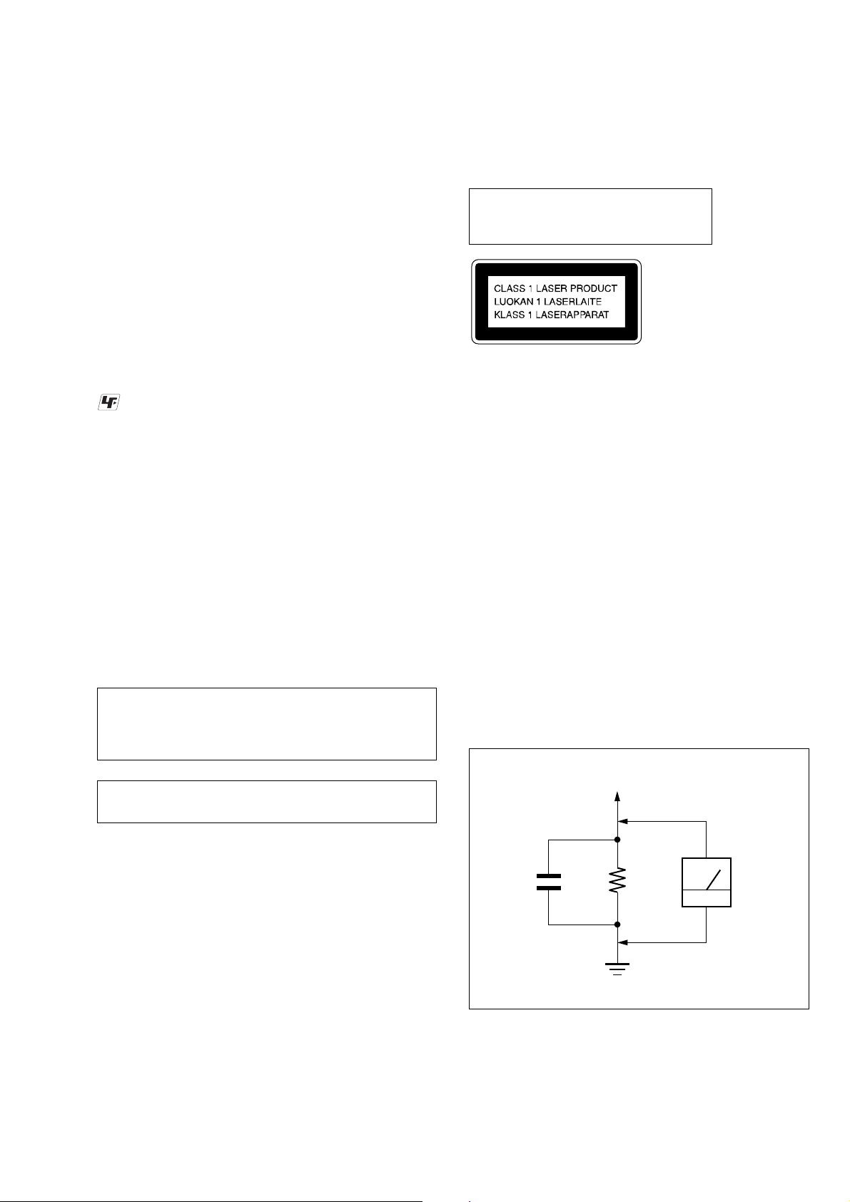
Laser component in this product is capable
of emitting radiation exceeding the limit for
Class 1.
This appliance is
claassified as a CLASS 1
LASER product. This
label is located on the
rear exterior.
SAFETY CHECK-OUT (US MODEL)
After correcting the original service problem, perform the following safety check before releasing the set to the customer:
Check the antenna terminals, metal trim, “metallized” knobs, screws,
and all other exposed metal parts for AC leakage.
Check leakage as described below.
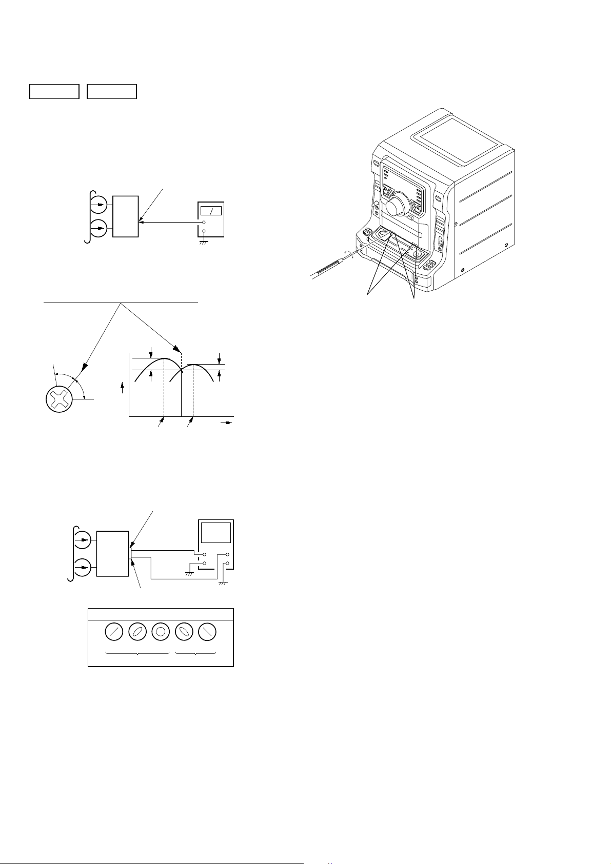
LEAKAGE TEST
The AC leakage from any exposed metal part to earth ground and
from all exposed metal parts to any exposed metal part having a
return to chassis, must not exceed 0.5 mA (500 microampers.).
Leakage current can be measured by any one of three methods.
1. A commercial leakage tester, such as the Simpson 229 or RCA
WT-540A. Follow the manufacturers’ instructions to use these
instruments.
2. A battery-operated AC milliammeter. The Data Precision 245
digital multimeter is suitable for this job.
3. Measuring the voltage drop across a resistor by means of a
VOM or battery-operated AC voltmeter. The “limit” indication is 0.75 V, so analog meters must have an accurate lowvoltage scale. The Simpson 250 and Sanwa SH-63Trd are examples of a passive VOM that is suitable. Nearly all battery
operated digital multimeters that have a 2 V AC range are suitable. (See Fig. A)
NOTES ON HANDLING THE OPTICAL PICK-UP BLOCK
OR BASE UNIT
The laser diode in the optical pick-up block may suffer electrostatic
breakdown because of the potential difference generated by the
charged electrostatic load, etc. on clothing and the human body.
During repair, pay attention to electrostatic break-down and also
use the procedure in the printed matter which is included in the
repair parts.
The flexible board is easily damaged and should be handled with
care.
Fig. A. Using an AC voltmeter to check AC leakage.
3
HCD-ZX9
Ver. 1.1
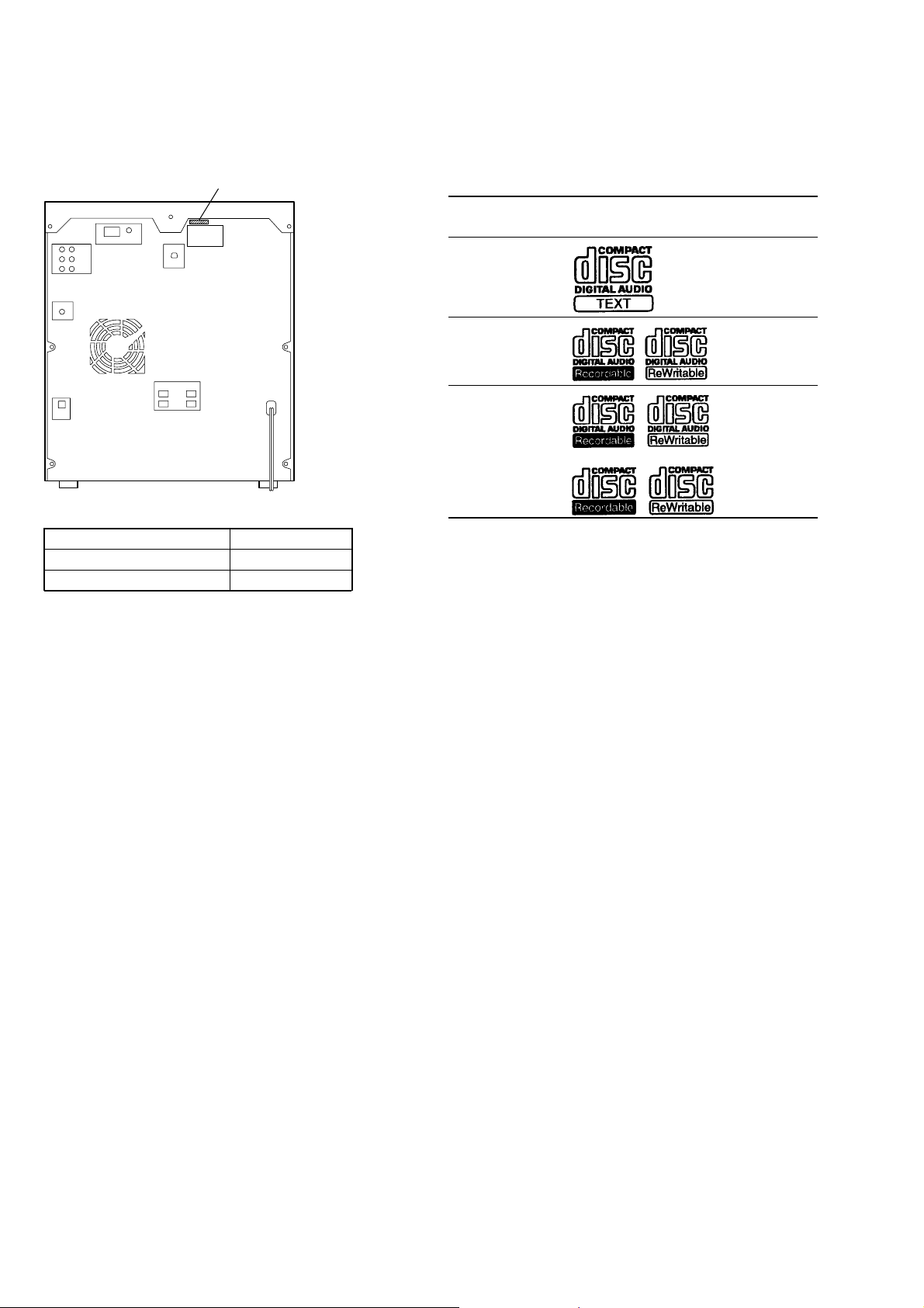
MODEL IDENTIFICATION
– BACK PANEL –
Par t No.
MODEL PART No.
Mexican 2-649-004-2s
US 2-649-004-3s
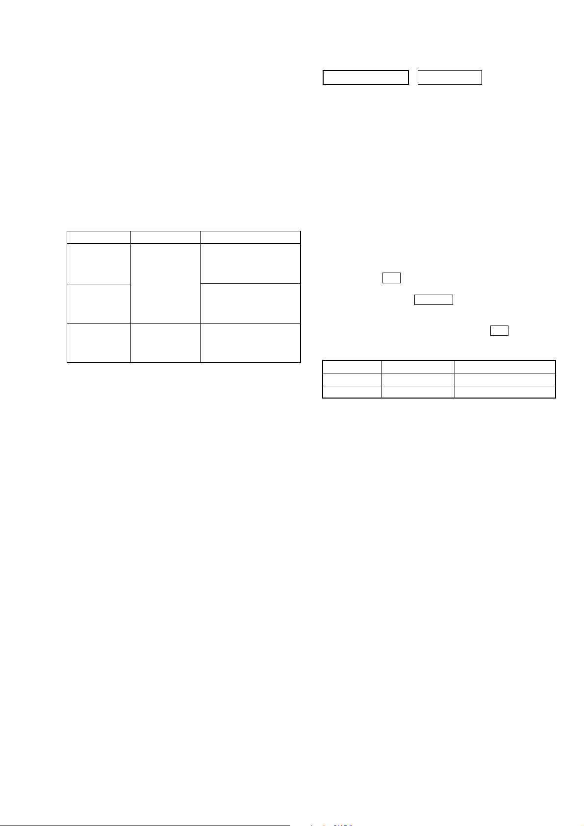
PLAYABLE DISC
You can playback the following discs on this system. The other
discs cannot be played back.
List of playable discs
Format of
discs
Audio CDs Audio
CD-R/CD-RW Audio
(Audio CDs)
CD-R/CD-RW Audio
(Discs with
MP3 audio
tracks)
Disc logo Contents
4

TABLE OF CONTENTS
HCD-ZX9
1. SERVICE NOTE
1-1. Service Position of CD BU Block....................................... 6
1-2. Service Position of TC Mechanism, Panel Board ............... 7
1-3. Service Position of Power Board ........................................ 8
1-4. Service Position of CD Changer ......................................... 8
2. GENERAL
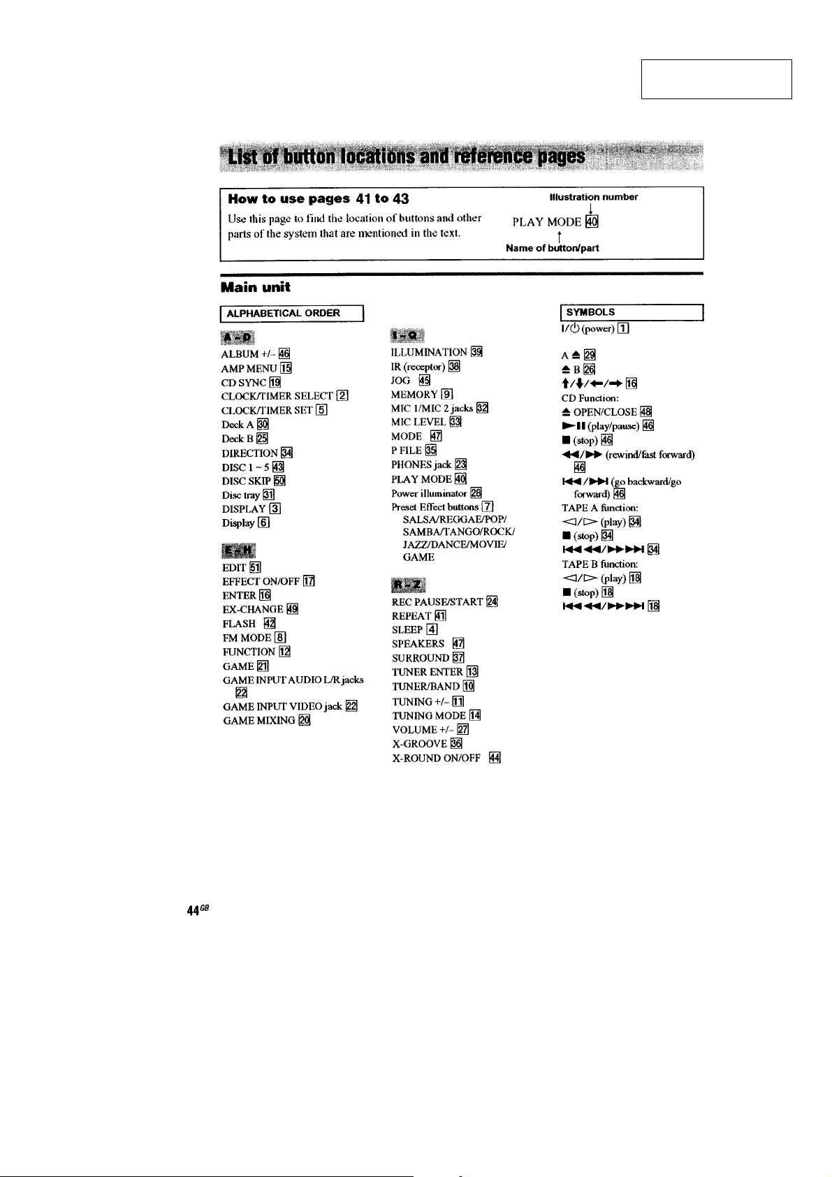
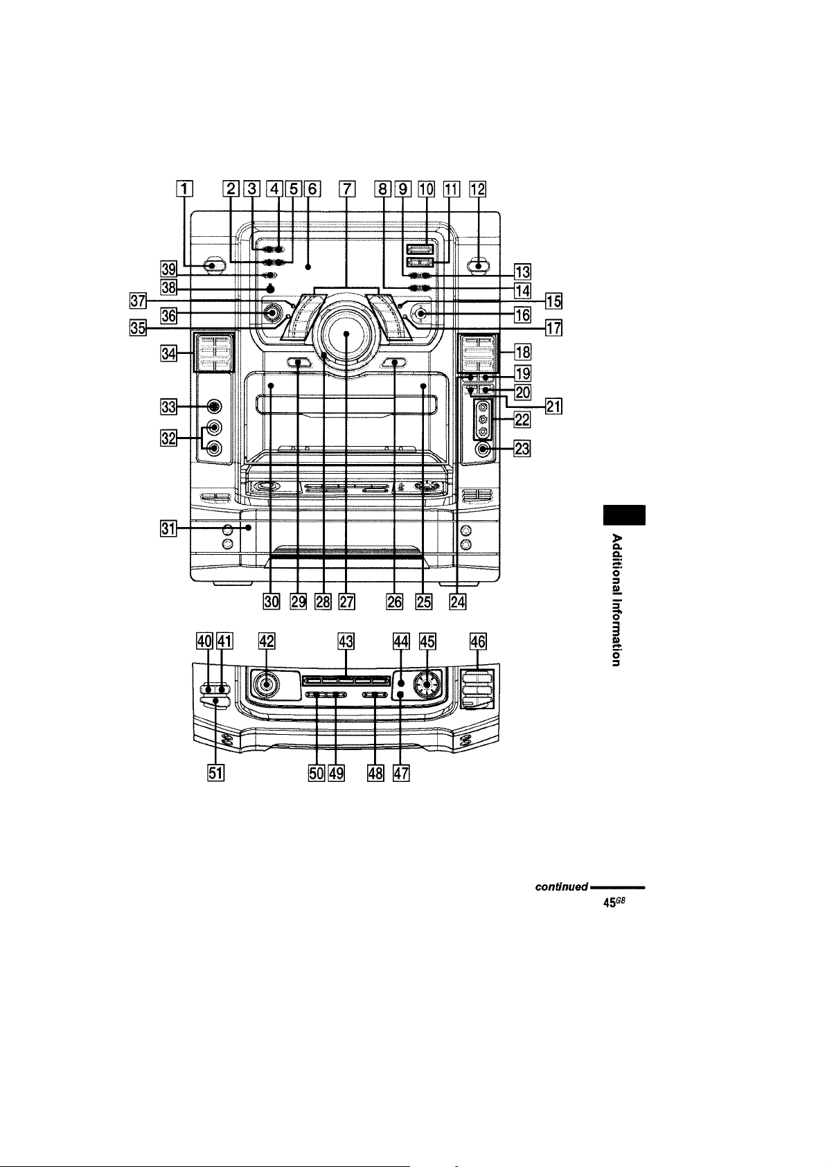
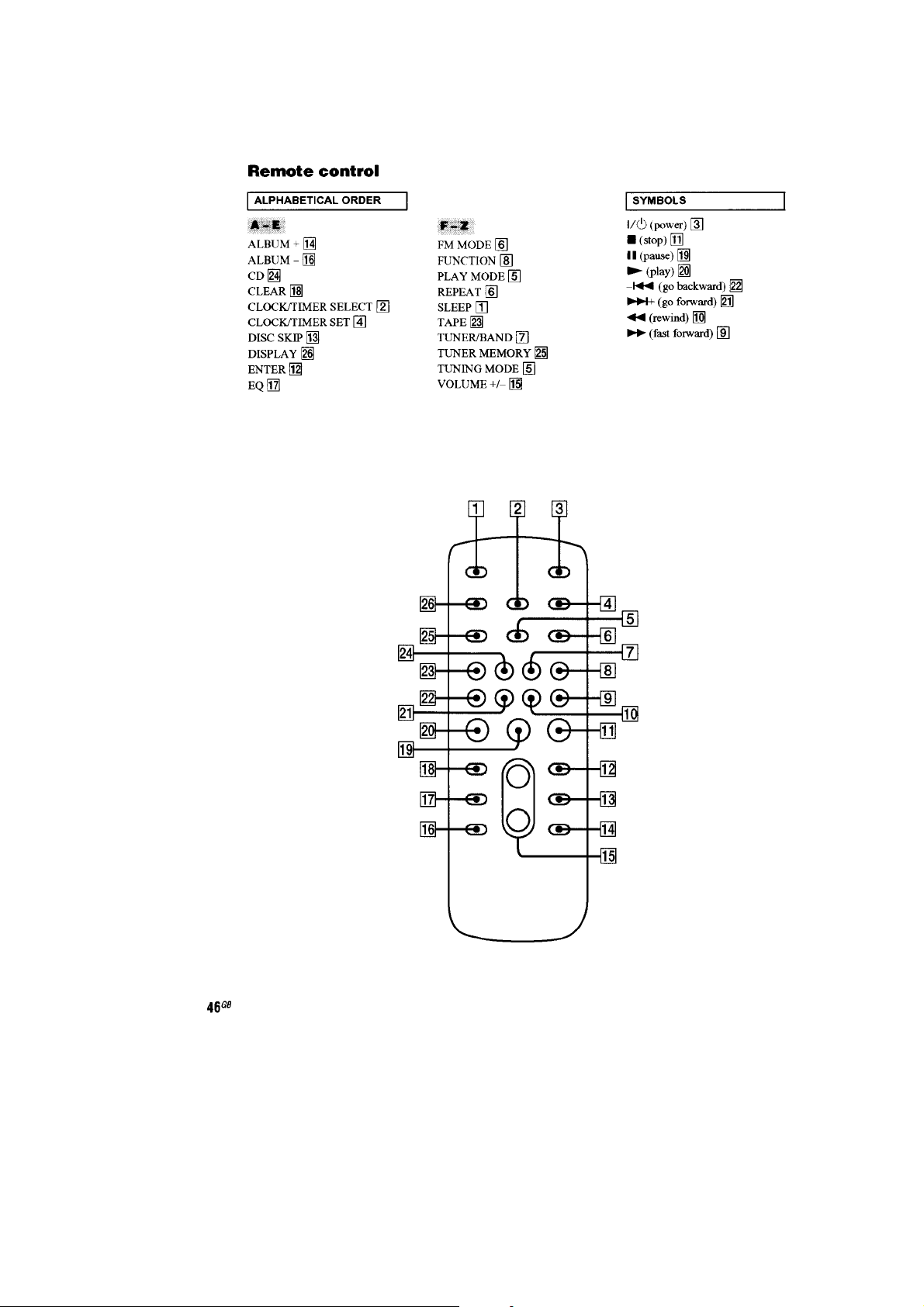
List of Button Locations and Reference Pages........................ 9
3. DISASSEMBLY
3-1. Case ................................................................................... 13
3-2. Loading Panel.................................................................... 13
3-3. Front Panel Section ........................................................... 14
3-4. Tape Mechanism Deck ...................................................... 14
3-5. Game-in/hp Board, Mic Board.......................................... 15
3-6. Back Panel Section............................................................ 15
3-7. CD Mechanism Section..................................................... 16
3-8. Main Board .......................................................................17
3-9. Table Assy ......................................................................... 17
3-10. SE-130 Board .................................................................... 18
3-11. TD Belt .............................................................................. 18
3-12. DC Motor (M901) ............................................................. 19
3-13. Optical Pick-up ................................................................. 19
3-14. BD81A Board ................................................................... 20
4. TEST MODE ..................................................................... 21
5. MECHANICAL ADJUSTMENTS...............................25
6. ELECTRICAL ADJUSTMENTS................................. 25
7. DIAGRAMS
7-1. Circuit Boards Location .................................................... 28
7-2. Block Diagram –CD Servo Section– ................................ 29
7-3. Block Diagram –Tuner/Tape Deck Section–.....................30
7-4. Block Diagram –Main Section–........................................31
7-5. Block Diagram –Display/Power Section– ........................ 32
7-6. Printed Wiring Board –BD Section–................................. 34
7-7. Schematic Diagram –BD Section–.................................... 35
7-8. Printed Wiring Boards –Loading Section– ....................... 36
7-9. Schematic Diagram –Loading Section–............................37
7-10. Schematic Diagram –Main Section (1/4)– ........................ 38
7-11. Schematic Diagram –Main Section (2/4)– ........................ 39
7-12. Schematic Diagram –Main Section (3/4)– ........................ 40
7-13. Schematic Diagram –Main Section (4/4)– ........................ 41
7-14. Printed Wiring Board –Main Section– .............................. 42
7-15. Printed Wiring Boards –Power Section–........................... 43
7-16. Schematic Diagram –Power Section (1/2)– ...................... 44
7-17. Schematic Diagram –Power Section (2/2)– ...................... 45
7-18. Printed Wiring Board –Panel Section–.............................. 46
7-19. Schematic Diagram –Panel Section– ................................ 47
7-20. Printed Wiring Boards –Volume Section– ........................ 48
7-21. Printed Wiring Board –Mic Section– ................................ 49
7-22. Schematic Diagram –Volume, Mic Section– .................... 50
7-23. Schematic Diagram –Switch Section– .............................. 51
7-24. Printed Wiring Boards –Switch Section (1/2)–................. 52
7-25. Printed Wiring Boards –Switch Section (2/2)–................. 53
7-26. Printed Wiring Boards –Jack Section–..............................54
7-27. Schematic Diagram –Jack Section– .................................. 55
7-28. Printed Wiring Board –Lighting Section–......................... 56
7-29. Schematic Diagram –Lighting Section– ........................... 56
7-30. Printed Wiring Board –Surround Section– ....................... 57
7-31. Schematic Diagram –Surround Section– .......................... 58
7-32. Printed Wiring Boards –Transformer Section–................. 59
7-33. Schematic Diagram –Transformer Section– ..................... 60
8. EXPLODED VIEWS
8-1. Back Panel Section............................................................ 71
8-2. Front Panel Section (1)...................................................... 72
8-3. Front Panel Section (2)...................................................... 73
8-4. Chassis Section ................................................................. 74
8-5. CD Mechanism Section (1) ............................................... 75
8-6. CD Mechanism Section (2) ............................................... 76
9. ELECTRICAL PARTS LIST ........................................ 77
5
HCD-ZX9
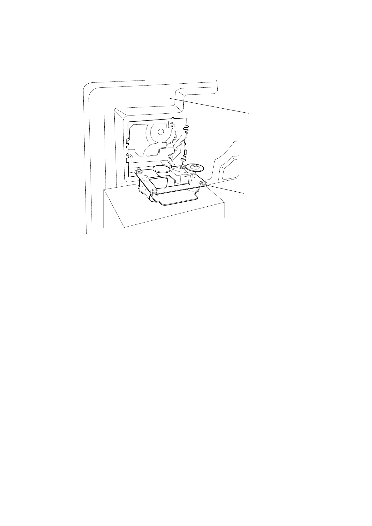
1-1. SERVICE POSITION OF CD BU BLOCK
SECTION 1
SERVICE NOTE
chassis
CD block
6
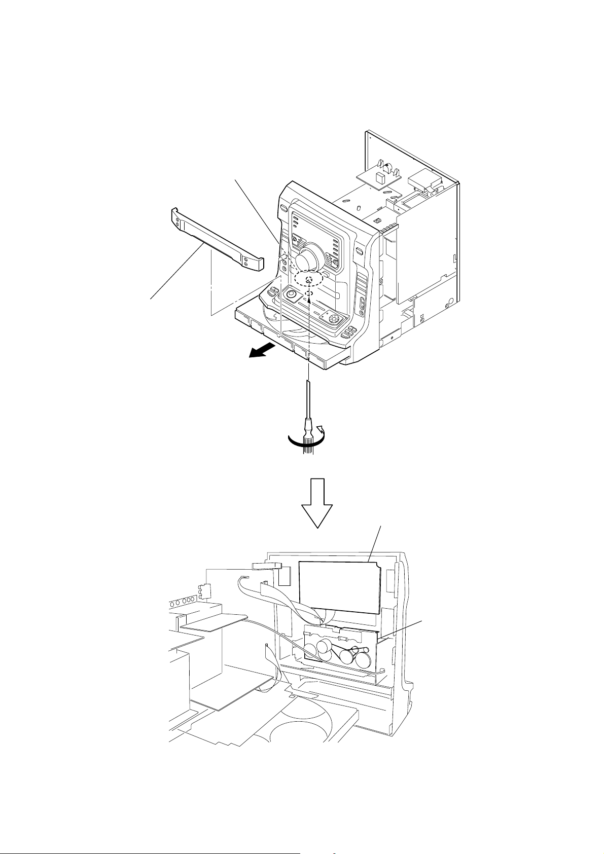
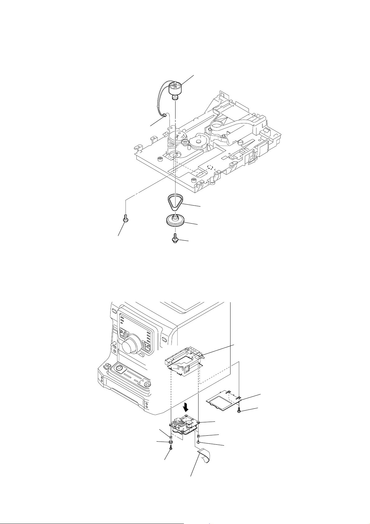
1-2. SERVICE POSITION OF TC MECHANISM, PANEL BOARD
k
gear (shaft)
3
loading panel
HCD-ZX9
2
1
Turn the gear (shaft) in the
direction of the arrow.
PANEL board
tape mechanism bloc
7
HCD-ZX9
k
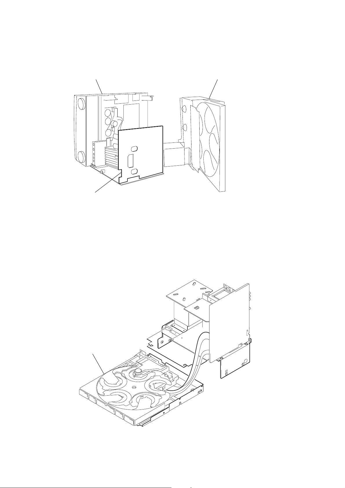
1-3. SERVICE POSITION OF POWER BOARD
front panel assy CD mechanism bloc
POWER board
1-4. SERVICE POSITION OF CD CHANGER
CD mechanism block
8
SECTION 2
GENERAL
HCD-ZX9
This section is extracted
from instruction manual.
9
HCD-ZX9
10
HCD-ZX9
11
HCD-ZX9
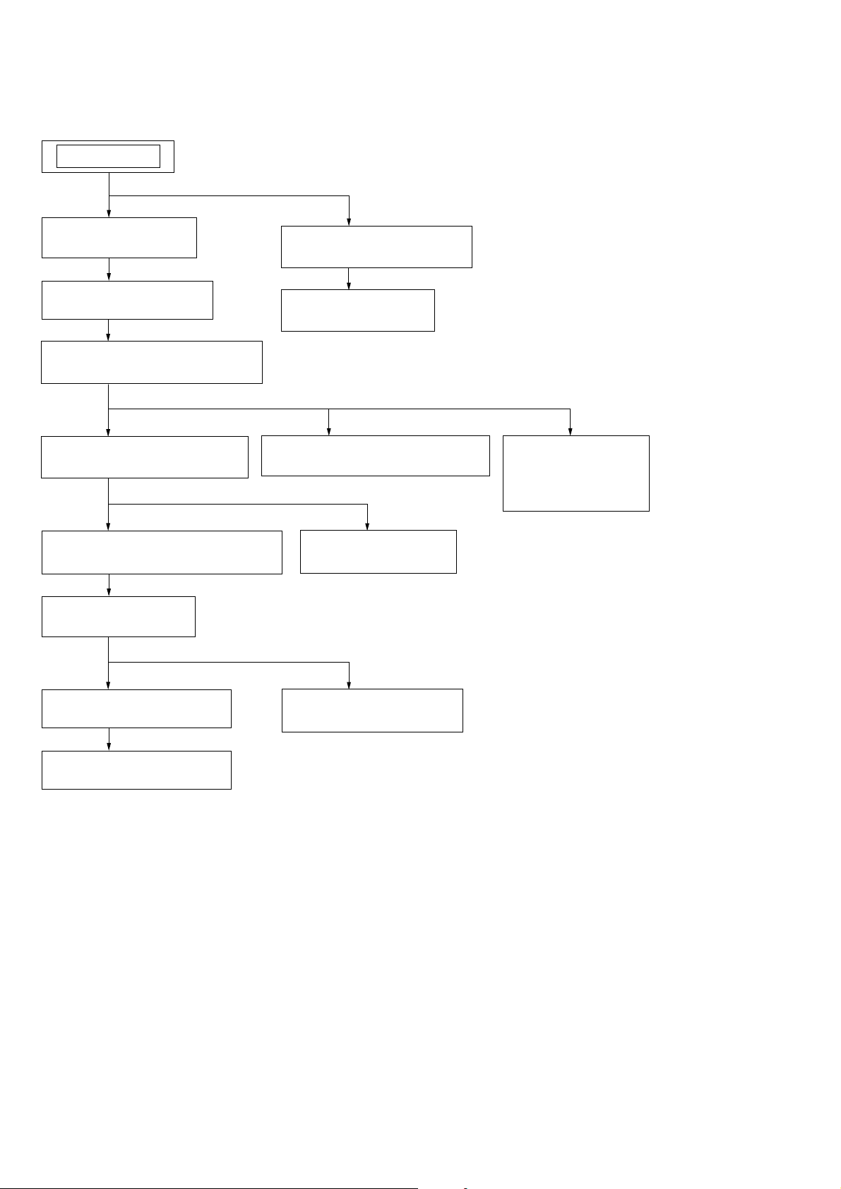
Note : Disassemble the unit in the order as shown below.
SET
SECTION 3
DISASSEMBLY
3-1. CASE
(Page 13)
3-2. LOADING PANEL
(Page 13)
3-3. FRONT PANEL SECTION
(Page 14)
3-6. BACK PANEL SECTION
(Page 15)
3-7. CD MECHANISM SECTION
(Page 16)
3-9. TABLE ASSY
(Page 17)
3-13. OPTICAL PICK-UP
(Page 19)
3-14. BD81A BOARD
(Page 20)
3-4. TAPE MECHANISM DECK
(Page 14)
3-8. MAIN BOARD
(Page 17)
3-5. GAME-IN/HP
BOARD,
MIC BOARD
(Page 15)
3-10. SE-130 BOARD
(Page 18)
3-11. TD BELT
(Page 18)
3-12. DC MOTOR (M901)
(Page 19)
12
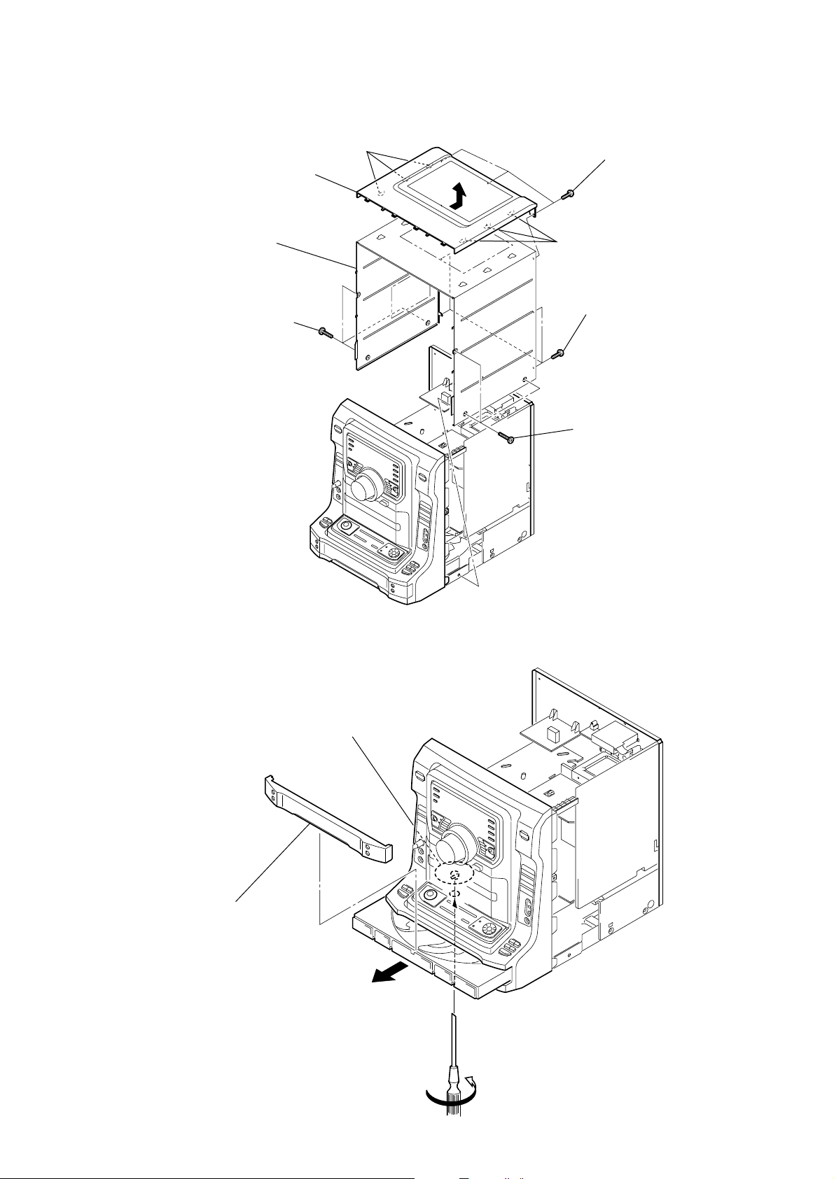
Note : Follow the disassembly procedure in the numerical order given.
3-1. CASE
HCD-ZX9
3
7
6
three
(case 3 TP2)
cover (top)
case
screws
three claws
2
1
three claws
4
four
(+BVTP 3
5
three
(case 3 TP2)
three
screws
(+BVTP 3
screws
×
screws
×
8)
8)
3-2. LOADING PANEL
3
loading panel
gear (shaft)
2
1
Turn the gear (shaft) in the
direction of the arrow.
13
HCD-ZX9
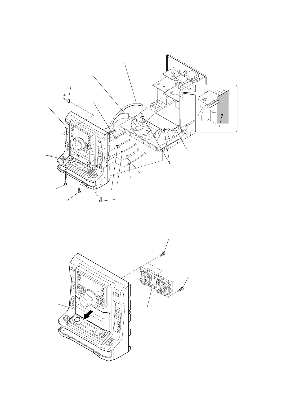
3-3. FRONT PANEL SECTION
3
4
CN920 (3P)
qd
front panel section
2
flexible flat cable (13 core)
(CN104)
flexible flat cable (21 core)
(CN507)
5
connector (3P)
MAIN board
two hooks
0
three
screws
(+BVTP 3
×
8)
qa
two
screws
(+BVTP 3
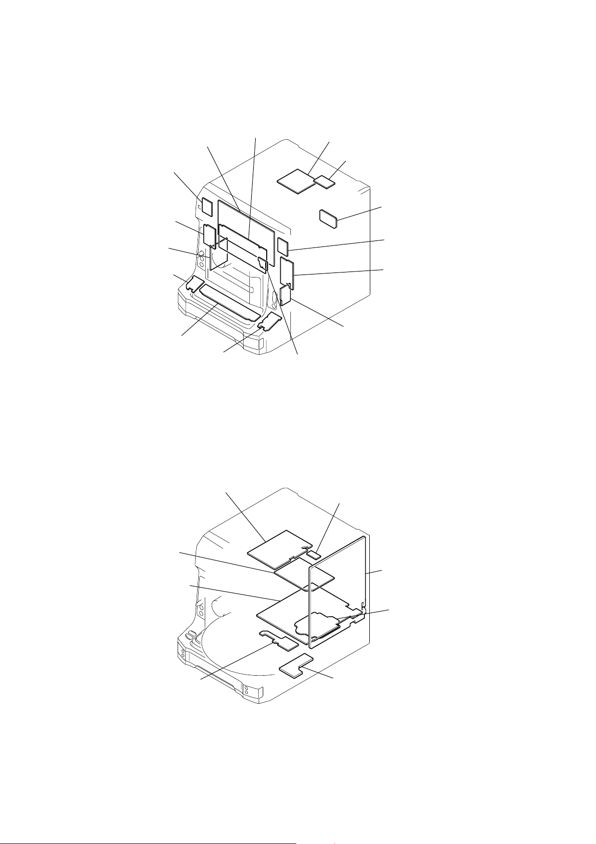
3-4. TAPE MECHANISM DECK
×
dust sheet
1
two holes
9
CN801 (4P)
8
CN803 (3P)
7
CN802 (2P)
6
connector (6P)
qs
three
screws
8)
(+BVTP 3
×
8)
3
three
screws
(+BVTP 2.6
×
8)
2
two
(+BVTP 2.6
screws
×
8)
14
lid (TC)
1
4
tape mechanism deck
3-5. GAME-IN/HP BOARD, MIC BOARD
)
)
0
qa
two clips
knob (MIC)
9
bracket (MIC)
8
four
(+BVTP 2.6
screws
qd
MIC board
qs
×
8)
screw
(+BVTP 2.6
6
7
×
8)
5
clip
4
bracket (game)
HCD-ZX9
two
screws
×
(+BVTP 2.6
GAME-IN/HP board
3
8)
four
screws
(+BVTP 2.6
×
8
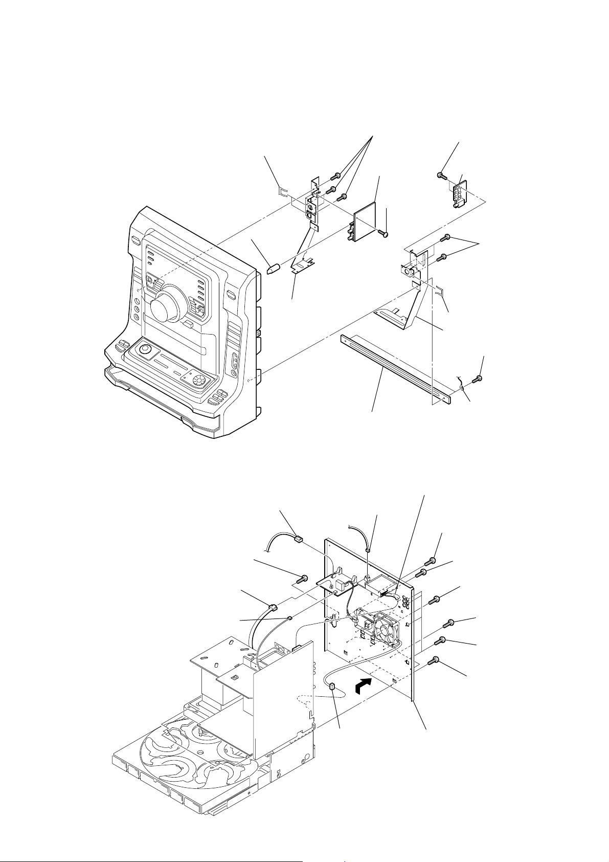
3-6. BACK PANEL SECTION
6
3
CN1004 (2P)
4
CN1000 (3P)
two
screws
(+BVTP 3
×
1
two
screws
×
×
8)
8)
8)
×
8)
×
8
(+BVTP 3
7
two
(+BVTP 3
8
two lugs
screws
two
screws
(+BVTP 3
9
two
(+BVTP 3
0
qa
×
8)
×
screws
five
screws
(+BVTP 3
four
screws
(+BVTP 3
2
bracket (center)
1
flexible flat cable (11 core)
2
CN1002 (2P)
8)
5
CN01 (3P)
(CN504)
qd
qf
CN513 (3P)
qs
qg
back panel section
three
screws
(+BVTP 3
×
8)
15
HCD-ZX9
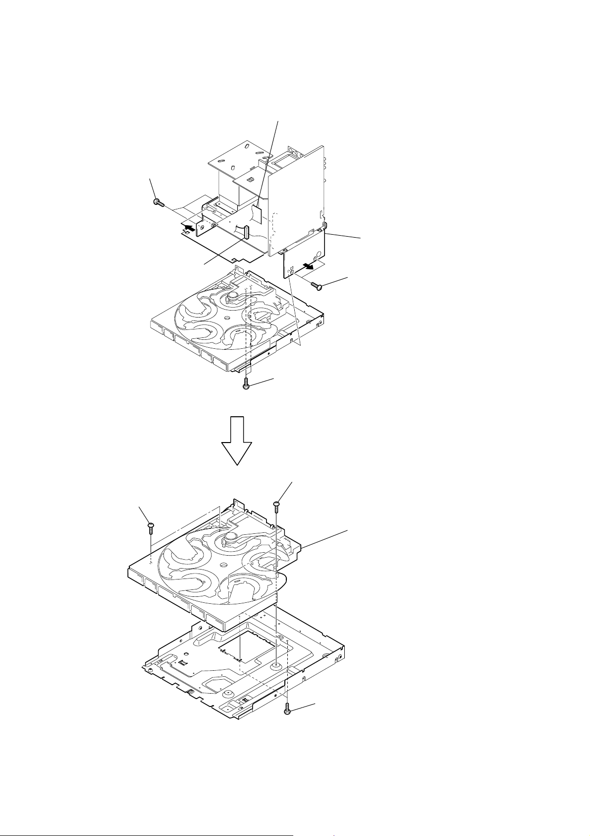
3-7. CD MECHANISM SECTION
5
three
screws
(+BVTP 3
×
1
CN509 (11P)
2
flexible flat cable (27 core)
(CN501)
8)
6
7
chassis section
6
4
two
(+BVTP 3
screws
×
8)
9
two
screws
(+BV 3 (3-CR))
3
two
(+BVTP 3
0
screws
×
8)
two
screws
(+BV 3 (3-CR))
CD mechanism section
qa
16
8
two
(+BVTP 3
screws
×
8)
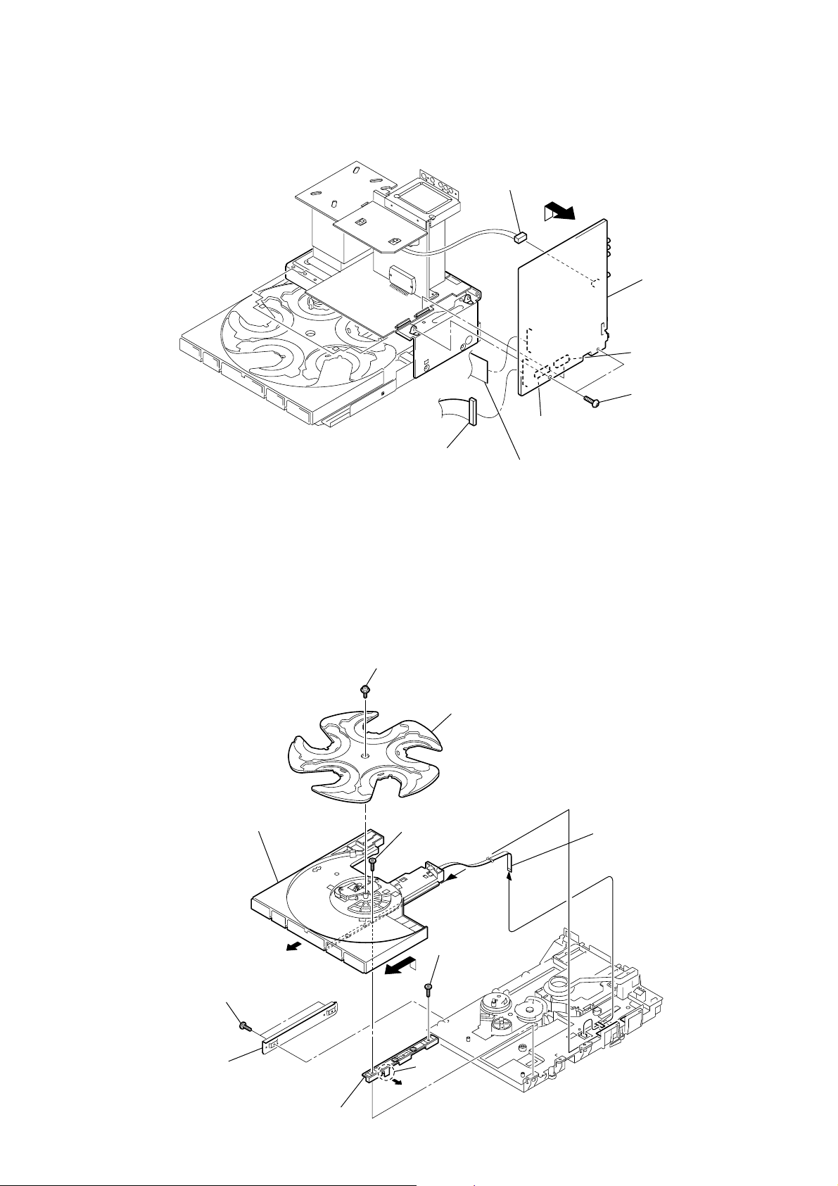
3-8. MAIN BOARD
)
)
1
CN502 (4P)
CN602
5
6
CN601
4
two
(+BVTP 3
MAIN board
screws
×
HCD-ZX9
8
3-9. TABLE ASSY
qs
table assy
3
1
floating
+PTPWH M2.6
(
7
screw
(+BTP 2.6
CN509 (11P)
screw
)
2
tray
×
2
flexible flat cable (27 core)
(CN501)
6
8)
flexible flat cable (6 core
(CN002) (FMS-18)
3
two
(+BTP 2.6
4
screws
bracket
×
8
claw
screw
(+BTP 2.6
×
8)
5
8)
0
plate (guide)
qa
9
17
HCD-ZX9
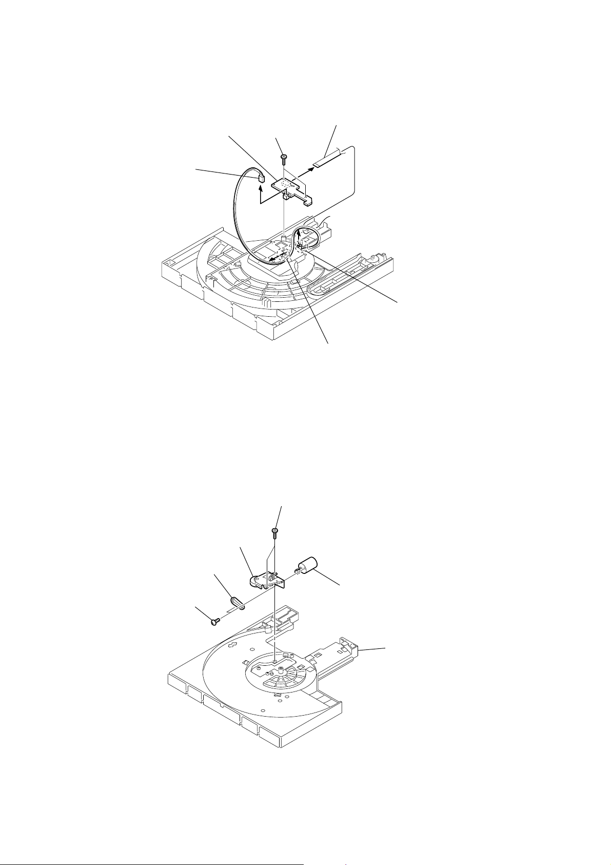
y
)
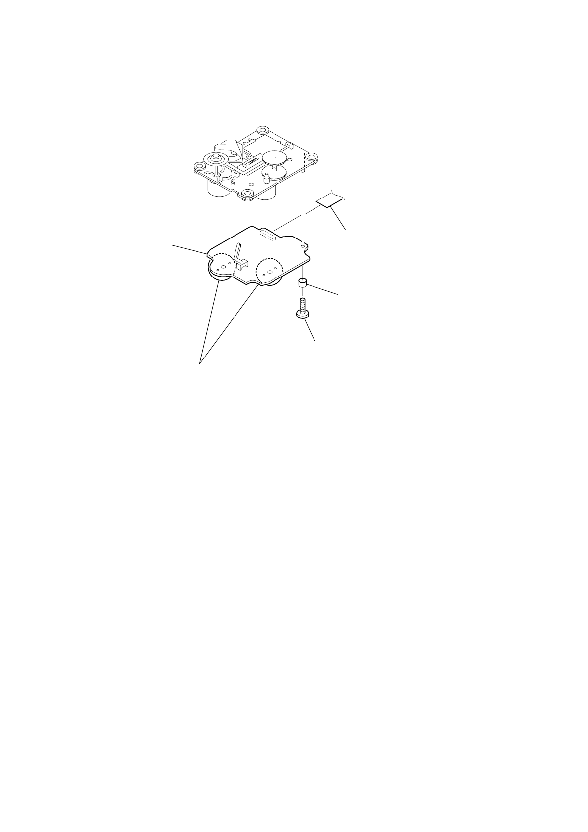
3-10. SE-130 BOARD
1
CN102 (2P)
6
SE-130 board
4
two
(+BTP 2.6
screws
×
5
8)
flexible flat cable (6 core
(CN101) (FMS-18)
3
claw
3-11. TD BELT
2
two
(+P 3
5
4
TD belt
screws
×
3)
TD unit assy
1
two
(+BTP 2.6
screws
2
×
claw
8)
3
TD motor assy
table ass
18
3-12. DC MOTOR (M901)
e
5
CN004 (2P)
6
DC motor (M901)
HCD-ZX9
3-13. OPTICAL PICK-UP
4
two
screws
(+P 2.6
3
belt (loading)
2
gear (loading A)
1
×
4)
screw
(+
PTPWH M2.6
)
holder (BU) assy
7
two coil spring (insulating)
6
two
stopper (BU)
5
8
two
screws
(+BVTP 2.6 (3CR))
9
optical pick-up
0
flexible flat cable (27 core)
(CN201)
4
two coil spring (insulating)
3
two floating
(+
2
1
screws
PTPWH M2.6
chassis plat
two
screws
(+BVTP 3
)
×
8)
19
HCD-ZX9
)
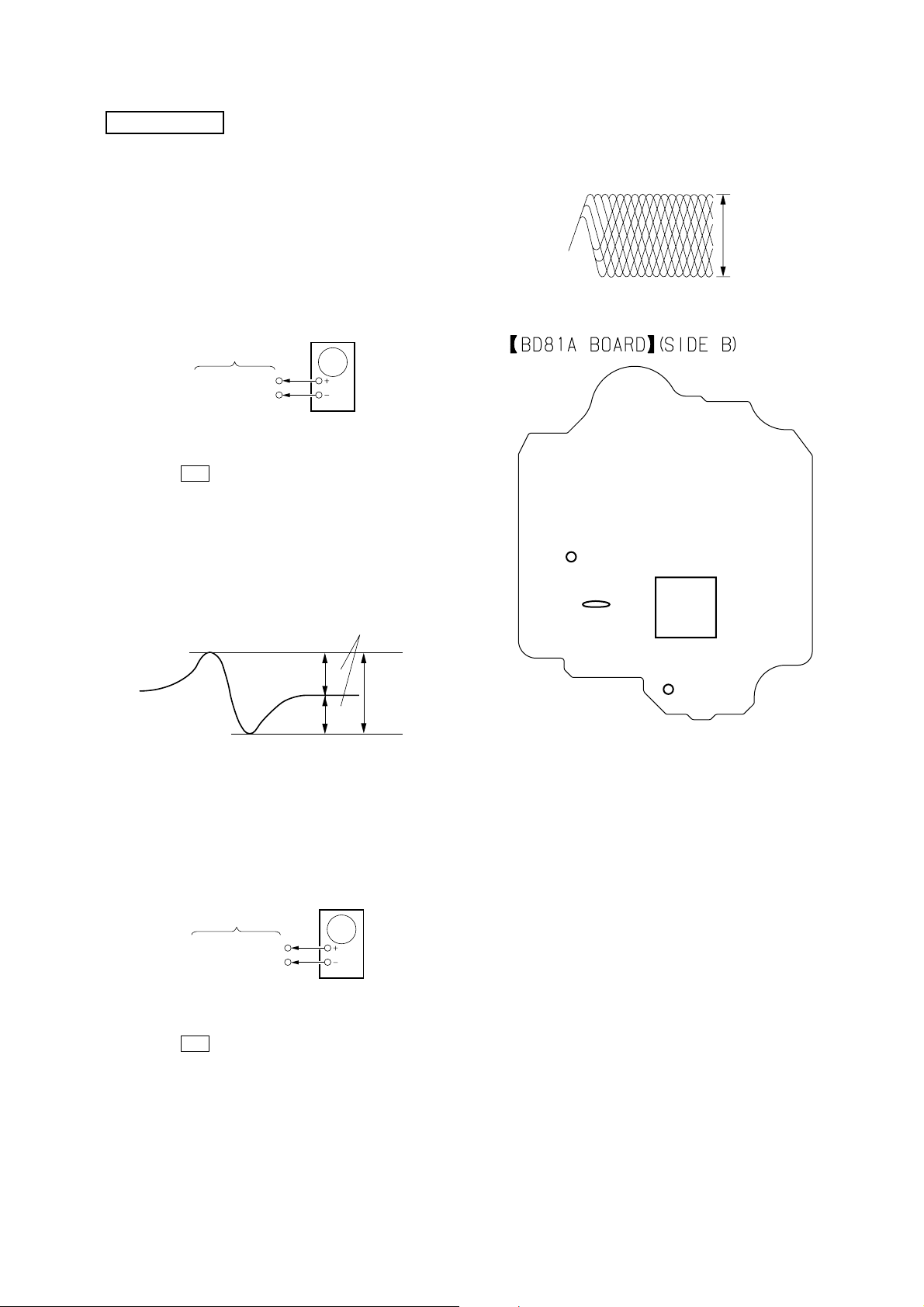
3-14. BD81A BOARD
5
BD81A board
1
optical pick-up (16 core
(CN101)
3
gap tube
4
Remove the four solders.
2
screw
(+BVTP 2.6 (3CR))
20

SECTION 4
TEST MODE
HCD-ZX9
[GC TEST MODE]
• This mode is used to check the fluorescent indicator tube, LED,
model, destination, software version, volume, ke y , jog and VACS
level.
Procedure:
1. Press x (TAPE B) button, [TUNER ENTER] button and [DISC
2] button simultaneously.
2. All LEDs and segments in fluorescent indicator tube are lighted
up.
3. When you want to enter the software version display mode,
press [DISC 1] button. The model and destination are displayed.
4. Each time [DISC 1] button is pressed, the display changes from
MC version, GC version, CD version, CDDM version, CDMA
version, CDMB version, BDA version, BDB version, ST version,
TC version, T A v ersion, TM version in this order , and returns to
the MC version display.
5. When [DISC 3] button is pressed while the version numbers are
being displayed except model and destination, the date of the
software creation appear. When [DISC 3] button is pressed again,
the display returns to the software version display . When [DISC
1] button is pressed while the date of the software creation is
being displayed, the date of the software creation is displayed
in the same order of software version display.
6. Press [DISC 2] button, the key check mode is activated.
7. In the key check mode, the fluorescent indicator tube displays
“K0 J0 V0”. Each time a button is pressed , “K” value increases.
However, once a button has been pressed, it is no longer taken
into account.
“J” value increases in the manner of 0, 1, 2, 3 ... if [JOG] is
turned clockwise, or it decreases in the manner of 0, 9, 8, 7 ... if
[JOG] knob is turned counter-clockwise.
“V” value increases in the manner of 0, 1, 2, 3 ... if [VOLUME]
knob is turned clockwise, or it decreases in the manner of 0, 9,
8, 7 ... if [VOLUME] knob is turned counter-clockwise.
8. When [DISC 3] button is pressed after all LEDs and segments in
fluorescent indicator tube light up, the fluorescent indicator tube
displays “VACS A APBB”. A is VA CS le vel which is trigger by
signal level while BB is VACS le vel which is trigger by APVA CS
(Abuse Protection VACS).
9. When [EX-CHANGE] button is pressed after all LEDs and
segments in fluorescent indicator tube light up, alternate
segments in fluorescent indicator tube would light up. If you
press [EX-CHANGE] button again, another half of altemate
segments in fluorescent indicator tube would light up. Pressing
[EX-CHANGE] button ag ain would cause all segments lights up.
10. To release from this mode, press three buttons in the same
manner as step 1, or disconnect the power cord.
[MC TEST MODE]
•This mode is used to check operations of the respective sections
of Amplifier, Tuner , and Tape.
3. When b button or B button is pressed, GEQ is set to flat and
a message “GEQ FLAT” appears on the fluorescent indicator
tube.
4. When the [VOLUME] knob is turned clockwise even slightly,
the sound volume increases to its maximum and a message
“VOLUME MAX” appears on the fluorescent indicator tube.
5. When the [VOLUME] knob is turned counter-clockwise even
slightly, the sound volume decreases to its minimum and a
message “VOLUME MIN” appears on the fluorescent indicator
tube.
•Tape function
1. When a tape is inserted in Deck B and recording is started, the
function is changed to VIDEO automatically . When [CD SYNC]
button is pressed during recording in function, ALC (Automatic
Logic Control) is turned on.
2. During recording, press . m (TAPE B) button will stop
the recording and the function is changed to T APE B and re wind
the tape in Deck B until the recording start position and playback
of the tape B is started. If the [REC PAUSE/START] button is
pressed for a pause and pressed again to resume recording during
recording time, when the tape is rewind, the tape will be rewind
until the position where the pause is applied.
• AMS Test Mode
1. Select the function “TAPE A” or “TAPE B”.
2. Select Loop or Relay direction mode by pressing the
[DIRECTION] button. Insert a test tape AMS-110A or AMS-120
to selected tape deck.
3. Press the [AMP MENU] button to enter the AMS test mode.
4. After the test tape is rewind to the beginning of the tape, the
AMS+ is checked, and the mechanism is shut off after detecting
the AMS signal twice.
5. Then the AMS– is checked and the mechanism is shut of f after
detecting the AMS signal twice.
6. When the check is complete, a message of either OK or NG
appears on the fluorescent indicator tube.
•To release from MC Test mode
1. To release from this mode, press ?/1 button.
2. The cold reset is enforced at the same time.
[COLD RESET]
• The cold reset clears all data including preset data stored in the
RAM to initial conditions. Execute this mode when returning
the set to the customer.
Procedure:
1. Press x (TAPE B) button, [TUNER ENTER] button, and ?/1
button simultaneously.
2. The fluorescent indicator tube becomes blank for a while, and
the set is reset.
Procedure:
•To enter MC Test Mode
1. Press x (TAPE B) button, [TUNER ENTER] button and [DISC
3] button simultaneously.
2. The 4 speaker symbols and CD ring indicators flash on the
fluorescent indicator tube. The function is changed to VIDEO.
• Check of Amplifier
1. When v button is pressed, GEQ increases to its maximum and
a message “GEQ MAX” appears on the fluorescent indicator
tube.
2. When V button is pressed, GEQ decreases to its minimum and
a message “GEQ MIN” appears on the fluorescent indicator
tube.
[VACS ON/OFF]
•This mode is used to switch ON and OFF the VACS (Variable
Attenuation Control System).
Procedure:
1. Press ?/1 button to turn the set ON.
2. Press [PLAY MODE] button and ?/1 button simultaneously.
The message “VACS OFF” or “VACS ON” appears on the
fluorescent indicator tube.
21
HCD-ZX9
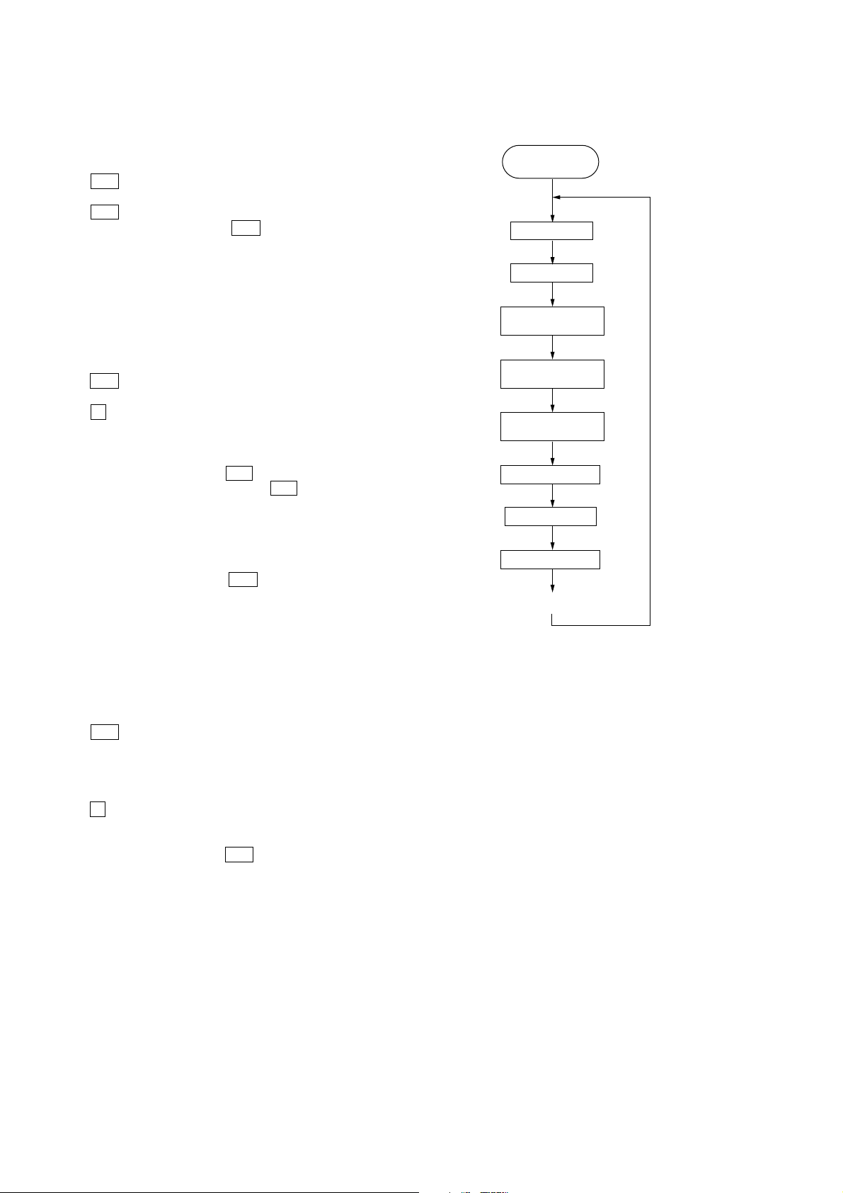
START
(from Disc 1)
TOC Reading
Play first track for 2
seconds
Play last track for 2
seconds
EX-CHANGE open/
close
Open the disc tray
Disc skip
Close the disc tray
Change the next disc
Disc Chucking
[TUNER STEP CHANGE]
•The step interval of AM channels can be toggled between 9 kHz
and 10 kHz.
Procedure:
1. Press ?/1 button to turn the set ON.
2. Press [TUNER BAND] button to select the “AM”.
3. Press ?/1 button to turn the set OFF.
4. Press [TUNER ENTER] button and ?/1 button simultaneously.
The system will turn ON automatically. The message “AM 9k
STEP” or “AM 10k STEP” appears on the fluorescent indicator
tube and thus the channel step is changed.
[CD SERVICE MODE]
•This mode let you move the CD sled motor freely . Use this mode
when you want to clean the optical pick-up.
Procedure:
1. Press ?/1 button to turn the set ON.
2. Select CD function.
3. Press x (TAPE B) button, [TUNER ENTER] button, and [DISC
5] button simultaneously.
4. The CD service mode is activated. The message “SERVICE
MODE” appears on the fluorescent indicator tube.
5. With the CD in stop status, press M (CD) button to move the
optical pick-up to outside track, or press m (CD) button to
move to inside track. The message “SLED OUT” or “SLED
IN” appears on the fluorescent indicator tube.
6. To turn on or off the laser, press [PLAY MODE] button. The
message “LASER ON” or “LASER OFF” appears on the
fluorescent indicator tube.
7. To release from this mode, press ?/1 button.
Aging mode sequence:
[AGING MODE]
• This mode can be used for operation check of CD section.
If an error occurs, the aging operation would stops and the
status is displayed.
If there were no error occurs, the aging operation would
continue repeatedly.
Procedure:
1. Press ?/1 button to turn the set ON.
2. Select CD function.
3. Load five discs on the disc tray.
4. Press [PLAY MODE] button to select the “ALL DISCS” mode,
and press the [REPEAT] button to select “REPEA T OFF” mode.
5. Press x (TAPE B) button, [TUNER ENTER] button, and [DISC
4] button simultaneously.
6. Aging operation is started.
7. T o release from this mode, press ?/1 button or disconnect the
power cord to turn the power OFF.
22
HCD-ZX9
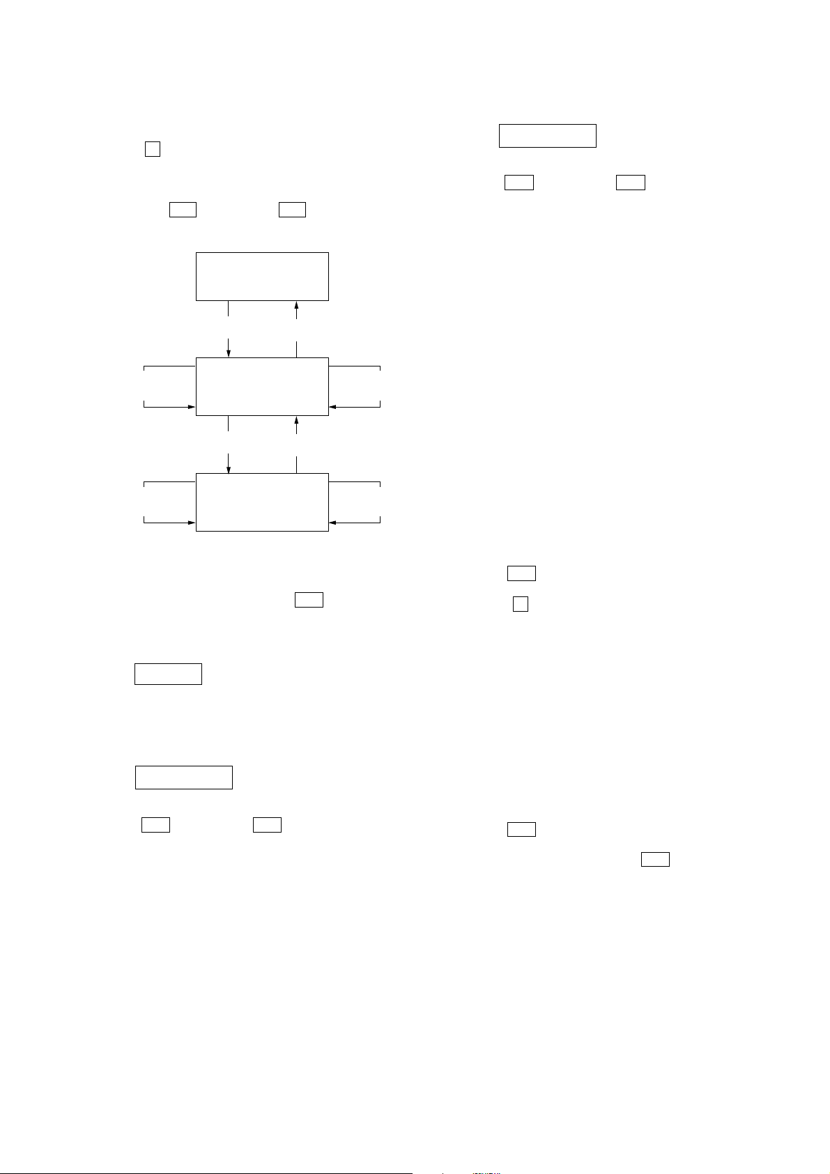
• Display when an error occurred (CD Error Code Mode)
Procedure:
1. Press x (TAPE B) button, [TUNER ENTER] button and [DISC
SKIP] button simultaneously to enter the error code display
mode.
2. The fluorescent indicator tube displays the number of total error.
3. Each time M (CD) button or m (CD) button is pressed,
display change as below.
Display of
Total Error
FF button
AMS (+)
button
FF button
AMS (+)
button
FR button
Display of
Mechanical
Error
FR button
Display of
No Disc
Error
AMS (–)
button
AMS (–)
button
• Display of no disc errors
D*$$%%&&##00
D*: The number of no disc error (“00” is latest one)
(Press > (CD) button or . (CD) button to display next
error)
$$: Error type
01: Focus error
02: GFS error
03: Setup error
%%: Not used
&&:
00: No disc judgment without chucking retry.
01: No disc judgment after chucking retry.
##: The state when judged as no disc
01: Stop
02: Setup
03: TOC reading
04: Access
05: Playback
06: Pause
07: Manual search (Play)
08: Manual search (Pause)
[CD REPEAT 5 LIMIT OFF MODE]
• The number of repeat for CD playback is 5 times when the
repeat mode is “REPEAT ALL”. This mode enables CD to
repeat playback for limitless times.
4. To clear the error record, operate the cold reset. (Refer to the
“MC COLD RESET”)
5. To release from this mode, press the ?/1 button or disconnect
the power plug to turn the power OFF.
• Display of total error
Em **Ed**
Em**: The number of mechanical errors.
Ed**: The number of no disc errors after chucking the disc.
• Display of mechanical errors
M*$$%%&&##00
M*: The number of mechanical error (“00” is latest one)
(Press > (CD) button or . (CD) button to display next
error)
$$: Not used
%%: Loading related error (Second figure is not used)
D: Stop by the problem other than mechanical problem
while closing.
E: Stop by the problem other than mechanical problem
while opening.
C: Stop by the problem other than mechanical problem
while chucking up.
F: Stop by the problem other than mechanical problem
while chucking down.
&&: Emerging error
01: Stop while chucking up.
02: Stop while chucking up.
03: Time-out of EX-CHANGE open.
05: Time-out of EX-CHANGE close.
##: Not used
Procedure:
1. Press ?/1 button to turn the set ON.
2. Select CD function.
3. Press x (TAPE B) button, [TUNER ENTER] button and
[REPEAT] button simultaneously to enter the CD repeat 5 limit
off mode and the fluorescent indicator tube displays “LIMIT
OFF”.
•To release from this mode, operate the cold reset. (Refer to the
“MC COLD RESET”)
[CD SHIP MODE (WITH MEMORY CLEAR)]
•This mode moves the optical pick-up to the position durable to
vibration and clears all data including preset data stored in the
RAM to initial conditions. Use this mode when returning the
set to the customer after repair.
Procedure:
1. Press ?/1 button to turn the set ON.
2. Select CD function.
3. Press [EXCHANGE] button and ?/1 button simultaneously.
The set will power off automatically.
4. After the “STANDBY” blinking display finish, a message
“LOCK” is displayed on the fluorescent indicator tube and the
CD ship mode is set.
23

HCD-ZX9
[CD SHIP MODE (WITHOUT MEMORY CLEAR)]
•This mode moves the optical pick-up to the position durable to
vibration. Use this mode when returning the set to the customer
after repair.
Procedure:
1. Press ?/1 button to turn the set ON.
2. Select CD function.
3. Press [REPEAT] button and ?/1 button simultaneously. The
set will power off automatically.
4. After the “STANDBY” blinking display finish, a message
“LOCK” is displayed on the fluorescent indicator tube and the
CD ship mode is set.
[CD POWER MANAGE]
•This mode let you switch on or off power supply to the BU
during TUNER function.
•When CD POWER is set to OFF, the power supply to the BU is
cut off during TUNER function. It will increase the time taken
to access CD when function change from TUNER to CD but it
will improve tuner reception.
•When CD POWER is set to ON, the power supply to the BU is
not cut off during TUNER function. It will reduce the time taken
to access CD when function change from TUNER to CD but it
will decrease tuner reception performance.
Procedure:
1. Press ?/1 button to turn the set ON.
2. Select CD function.
3. Press ?/1 button to turn the set OFF.
4. Press x (CD) button and ?/1 button simultaneously. The set
will power on automatically.
5. The message “CD POWER ON” or “CD POWER OFF” will
be displayed on the fluorescent indicator tube.
[CD TRAY LOCK MODE]
•This mode let you lock the disc tray. When this mode is activated, the disc tray will not open when [OPEN/CLOSE] button
or [EX-CHANGE] button is pressed. The message “LOCKED”
will be displayed in on the fluorescent indicator tube.
Procedure:
1. Press ?/1 button to turn the set ON.
2. Select CD function.
3. Press x (CD) button and [OPEN/CLOSE] button simultaneously
and hold down until “LOCKED” or “UNLOCKED” displayed
on the fluorescent indicator tube (around 5 seconds).
[VIDEO/MD SWITCHING]
•This mode let you switch from VIDEO to MD and vice-versa.
Procedure:
1. During Power Off, press [FUNCTION] button and ?/1 button
simultaneously. The set power on automatically and the function
will changed to MD. Do the same procedures again to change
from MD to VIDEO.
24
SECTION 5
MECHANICAL ADJUSTMENTS
HCD-ZX9
SECTION 6
ELECTRICAL ADJUSTMENTS
Precaution
1. Clean the following parts with a denatured alcohol-moistened
swab:
record/playback heads pinch rollers
erase head rubber belts
capstan idlers
2. Demagnetize the record/playback head with a head
demagnetizer.
3. Do not use a magnetized screwdriver for the adjustments.
4. After the adjustments, apply suitable locking compound to the
parts adjusted.
5. The adjustments should be performed with the rated power
supply voltage unless otherwise noted.
Torque Measurement
Mode Torque Meter Meter Reading
2.9 – 6.9 mN • m
FWD (30 to 70 g • cm)
CQ-102C (0.42 – 0.97 oz • inch)
FWD
back tension
FF/REW CQ-201B (80 to 170 g • cm)
0.19 – 0.59 mN • m
(2 to 6 g • cm)
(0.03 – 0.08 oz • inch)
7.8 – 16.7 mN • m
(1.11 – 2.36 oz • inch)
DECK SECTION
Precaution
1. Demagnetize the record/playback head with a head
demagnetizer.
2. Do not use a magnetized screwdriver for the adjustments.
3. After the adjustments, apply suitable locking compound to the
parts adjust.
4. The adjustments should be performed with the rated power
supply voltage unless otherwise noted.
5. The adjustments should be performed in the order given in this
service manual. (As a general rule, playback circuit adjustment
should be completed before performing recording circuit
adjustment.)
6. The adjustments should be performed for both L-CH and RCH.
7. Switches and controls should be set as follows unless otherwise
specified.
8. Set to the test mode.
(1) Press the ?/1 button to turn the power ON.
(2) Select the function “TAPE A or B”.
(3) Press the button of x (TC-B) , [TUNER ENTER], and [DISC
3] simultaneously, to set the tape dec k test mode and displays
“TEST MODE” on the fluorescent indicator tube.
(4) To release from the test mode, press the ?/1 button.
•Test Tape
Tape Signal Used for
P-4-A100 10 kHz, –10 dB Azimuth Adjustment
WS-48B 3 kHz, 0 dB Tape Speed Adjustment
0 dB=0.775 V
25
HCD-ZX9
)
Record/Playback Head Azimuth Adjustment
DECK A DECK B
Note: Perform this adjustments for both decks
Procedure:
1. Mode: Playback (FWD)
test tape
P-4-A100
(10 kHz, – 10 dB)
2. Turn the adjustment scre w and check output peaks. If the peaks
do not match for L-CH and R-CH, turn the adjustment screw
so that outputs match within 1dB of peak.
L-CH
peak
Output
level
MAIN board
VIDEO/MD OUT jack (J701)
L-CH, R-CH
level meter
set
within
1dB
+
within
1dB
Adjustment Location: Playback Head (Deck A).
Record/Playback/Erase Head (Deck B).
forward
reverse
R-CH
Screw
position
peak
L-CH
peak
R-CH
peak
Screw
position
3. Mode: Playback
test tape
P-4-A100
(10 kHz, – 10 dB)
L-CH
set
R-CH
in phase 45°90°135°180
4. Repeat step 1 to 3 in playback (REV) mode.
MAIN board
VIDEO/MD
L-CH
R-CH
waveform of oscilloscope
good
OUT jack (J701
oscilloscope
wrong
H
V
°
5. After the adjustments, apply suitable locking compound to the
pats adjusted.
26
HCD-ZX9
p
p
CD SECTION
Note:
1. CD Block is basically designed to operate without adjustment.
Therefore, check each item in order given.
2. Use YEDS-18 (3-702-101-01) unless otherwise indicated.
3. Use an oscilloscope with more than 10M impedance.
4. Clean the object lens by an applicator with neutral detergent
when the signal level is low than specified value with the
following checks.
S-Curve Check
Oscilloscope
BD81A board
TP0102(FE1)
TP117(VC)
Procedure:
1. Connect oscilloscope to TP102 (FE1) and TP117 (VC).
2. Press the ?/1 button to turn the power ON.
3. Load a disc (YEDS-18) and actuate the focus search. (In
consequence of open and close the disc tray, actuate the focus
search)
4. Confirm that the oscilloscope waveform (S-curve) is
symmetrical between A and B. And confirm peak to peak level
within 3 ±0.5 Vp-p.
S-curve waveform
symmetry
Note: Clear RF signal waveform means that the shape “◊” can be
clearly distinguished at the center of the waveform.
VOLT/DIV : 200mV
TIME/DIV : 500ns
±
level : 1.3
0.3Vp-
Checking Location:
TP117
(VC)
TP0102
(FE1)
IC101
A
±
within 3
B
0.5Vp-
Note: •Try to measure sev eral times to make sure than the ratio of
A : B or B : A is more than 10 : 7.
•Take sweep time as long as possible and light up the
brightness to obtain best waveform.
RF Level Check
oscilloscope
BD81A board
TP124(RFACO)
TP117(VC)
Procedure:
1. Connect oscilloscope to TP124 (RFACO) and TP117 (VC).
2. Press the ?/1 button to turn the power ON.
3. Load a disc (YEDS-18) and playback.
4. Confirm that oscilloscope waveform is clear and check RFAC
signal level is correct or not.
TP124
(RFACO)
27
HCD-ZX9
d
d
7-1. CIRCUIT BOARDS LOCATION
SECTION 7
DIAGRAMS
PANEL board
POWER SWITCH board
TC-A board
MIC board
CD-L board
JOG board
CD-R board
VOL board
VOLTAGE SELECTOR board
LIGHTING board
POWER SWITCHING
FUNCTION SW boar
TC-B board
GAME-IN/HP board
CURSOR board
SURROUND board
POWER board
SE-130 board
TRANS board
SENSOR board
MAIN board
BD81A boar
MD-94 board
28
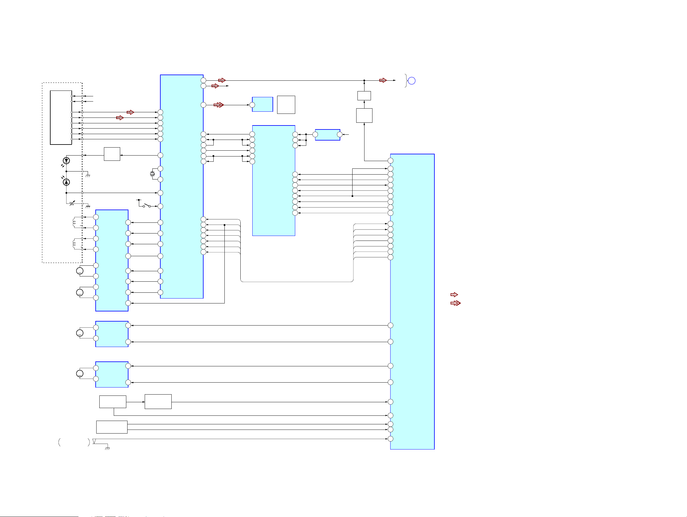
7-2. BLOCK DIAGRAM — CD SERVO SECTION —
RF AMP,DIGITAL
OPTICAL PICK-UP
BLOCK
(KSM-215DCP)
DETECTOR
VC
VCC
A
B
C
D
E
F
GND
VR
FOCUS
COIL
TRACKING
COIL
M101
(SPINDLE)
M102
(SLED)
+1.7V
+3.3V
SL/SP MOTOR
16
CH2OUT-F
15
CH2OUT-R
17
CH1OUT-R
18
CH1OUT-F
19
CH4OUT-R
20
CH4OUT-F
21
CH3OUT-F
CH3OUT-R
22
LD
DRIVER
Q10
DRIVE
IC251
CH1FIN
CH1RIN
CH2FIN
CH2RIN
CH3RIN
CH3FIN
OPIN+
MUTE
16.9344MHz
+3.3V
5
6
7
8
30
29
3
24
X171
S101
(LIMIT)
LD
PD
F+
F
T+
T
M
M
SIGNAL PROCESSOR
IC101
26
A
27
B
28
C
29
D
19
E
20
F
36
LD
XTAO
77
XTAI
78
37
PD
7
PD
11
TFDR
12
TRDR
13
FFDR
14
FRDR
SFDR
9
SRDR
10
6
MPD
AOUT1
AOUT2
DOUT
PCMDI
LRCKI
LRCK
PCMD
BCK
BCKI
XTACN
XRST
DATA
XLAT
CLOCK
SENS
SCOR
100
102
104
105
107
115
HCD-ZX9
A
IC401 (1/4)
MAIN
SECTION
(Page 31)
• R-ch is omitted due to same as L-ch.
• SIGNAL PATH
: CD PLAY(ANALOG OUT)
:
CD PLAY(DIGITAL OUT)
81
86
71
61
62
63
65
66
60
95
R-CH
XTACN
XRST
DATA
XLAT
CLOCK
SENS
SCOR
DIGITAL OUT
IC503
2
DOUT
11
SDO0
16
LRCKIA
19
SFSY/LRCKIB
14
SDIO
15
BCKIA
18
SBSY/BCKIB
DIGITAL
(OPTICAL)
MP3 DECODER
IC301
STANBY
PO11/BUCK/AD14
CD
OUT
VDD
VDD
VDDM
MIACK
MICK
MIDIO
MILP
MICS
RESET
MUTE
Q551
CD MUTE
CONTROL
Q535,536
55
21
40
3
36
8
7
6
5
4
2
+1.5V REG
5 1
IC303
+3.3V
SCOR
SENS
CLOCK
XLT
DATA
XRST
XTACN
CD L
SYSTEM CONTROL
CD A MUTE
41
MP3 DATA IN
6
MP3 STB
31
MP3 REQ
100
1
MP3 ACK
7
MP3 CLK
5
MP3 DATA OUT
2
MP3 LP
3
MP3 CS
18
MP3 RST
SCOR
19
21
SENS
CD CLK
22
XLAT
23
CD DATA
24
XRST
25
XTCN
26
M901
(LOADING)
M902
(TURN TABLE)
TRAY POSITION
DETECT
S901
LOADING MOTOR DRIVER
4
M
2
TABLE MOTOR DRIVER
4
M
2
IC515
OUT1
OUT2
OUT1
OUT2
ROTARY ENCODER
RIN
IC514
RIN
TABLE SENSOR
PH101,102
RE901
FIN
FIN
9
7
9
7
TBL ADDRESS
SENS SWITCH
Q870
49
50
47
48
43
42
44
45
46
LOG NEG
LOG POS
TBL NEG
TBL POS
DSENS
TSENS
OC SW1
CHK SW
OC SW2
HCD-ZX9
29 29
 Loading...