

Sony HCD-ZX70DVD Service Manual

HCD-ZX70DVD
SERVICE MANUAL
SUPPLEMENT-1
File this supplement with the service manual.
Subject: 1. Correction
2. Servicing Note
3. Service Mode
4. T est Mode
5. Electrical Adjustments
6. Block Diagrams
7. IC Block Diagrams
8. IC Pin Function Description
US Model
Canadian Model
AEP Model
UK Model
E Model
Australian Model
Chinese Model
TABLE OF CONTENTS
1. CORRECTION
1-1. Schematic Diagrams ....................................................... 2
1-2. Electrical Parts List ......................................................... 3
2. SERVICING NOTE .................................................. 4
3. SERVICE MODE...................................................... 5
4. TEST MODE.............................................................. 7
5. ELECTRICAL ADJUSTMENTS
DECK Section ................................................................. 17
VIDEO Section ............................................................... 20
6. BLOCK DIAGRAMS
6-1. Block Diagram – SERVO Section – .............................. 21
6-2. Block Diagram
– SIGNAL PROCESS/VIDEO Section –....................... 22
6-3. Block Diagram
– DVD/CD AUDIO, DVD/CD PLL Section – .............. 23
6-4. Block Diagram – DVD/CD MAIN Section –................ 24
6-5. Block Diagram – TUNER/TAPE DECK Section – ...... 25
6-6. Block Diagram – MAIN Section (1/2) – ....................... 26
6-7. Block Diagram – MAIN Section (2/2) – ....................... 27
6-8. Block Diagram – DISPLAY Section – .......................... 28
6-9. Block Diagram – POWER SUPPLY Section – ............. 29
7. IC BLOCK DIAGRAMS........................................ 30
8. IC PIN FUNCTION DESCRIPTION................ 30
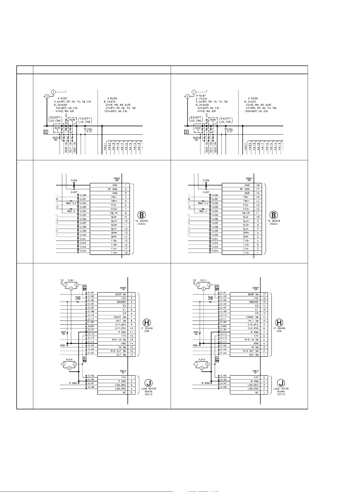
1. CORRECTION
1-1. SCHEMATIC DIAGRAMS
! : Indicates corrected portion.
Page INCORRECT CORRECT
– MB Board (1/10) – Location : B-7
28
– MB Board (8/10) – Location : G-18
35
– MB Board (1/10) – Location : B-7
^
– MB Board (8/10) – Location : G-18
^
(Page 25) (Page 25)
– MB Board (10/10) – Location : I-14
37
• Abbreviation
AR : Ar gentine model
AUS : Australian model
CH : Chinese model
CND: Canadian model
EA : Saudi Arabia model
HK : Hong Kong model
MX : Mexican model
MY : Malaysia model
SP : Singapore model
TH : Thai model
TW : Taiwan model
– MB Board (10/10) – Location : I-14
^
(Page 39) (Page 39)
^
(Page 41)
(Page 41)
2

1-2. ELECTRICAL PARTS LIST
Page INCORRECT CORRECT
Ref. No. Part No. Description RemarkRef. No. Part No. Description Remark
R237 1-216-216-00 RES-CHIP 5.6K 5% 1/8W
88
• Abbreviation
CH : Chinese model
HK : Hong Kong model
MY : Malaysia model
SP : Singapore model
TH : Thai model
TW : Taiwan model
(MY, SP, HK, TH, TW, CH)
R237 1-216-208-00 RES-CHIP 2.7K 5% 1/8W
R237 1-216-216-00 RES-CHIP 5.6K 5% 1/8W
(CH)
(MY, SP, HK, TH, TW)
3
2. SERVICING NOTE
CDM SHIP MODE
In sending the set back to the customers, place the set in the CDM
SHIP MODE through the procedure given below.
If the dummy disc is not inserted in the set returned from the
customers, ask customers for sending it or add new dummy disc
(Part No.: 4-228- 906-01 DISC, DUMMY).
Procedure:
1. Press the I/1 button to turn the power on.
2. Press the Z 1 button to open the disc tray 1, and put the dummy
disc.
3. Press the I/1 button, and the disc tray will close and chucking
the disc automatically.
4. Unplug the power cord when the demo display or clock display
appears on the fluorescent display tube.
Note: Peel off the protection sheets on both sides, if present on the dummy
disc.
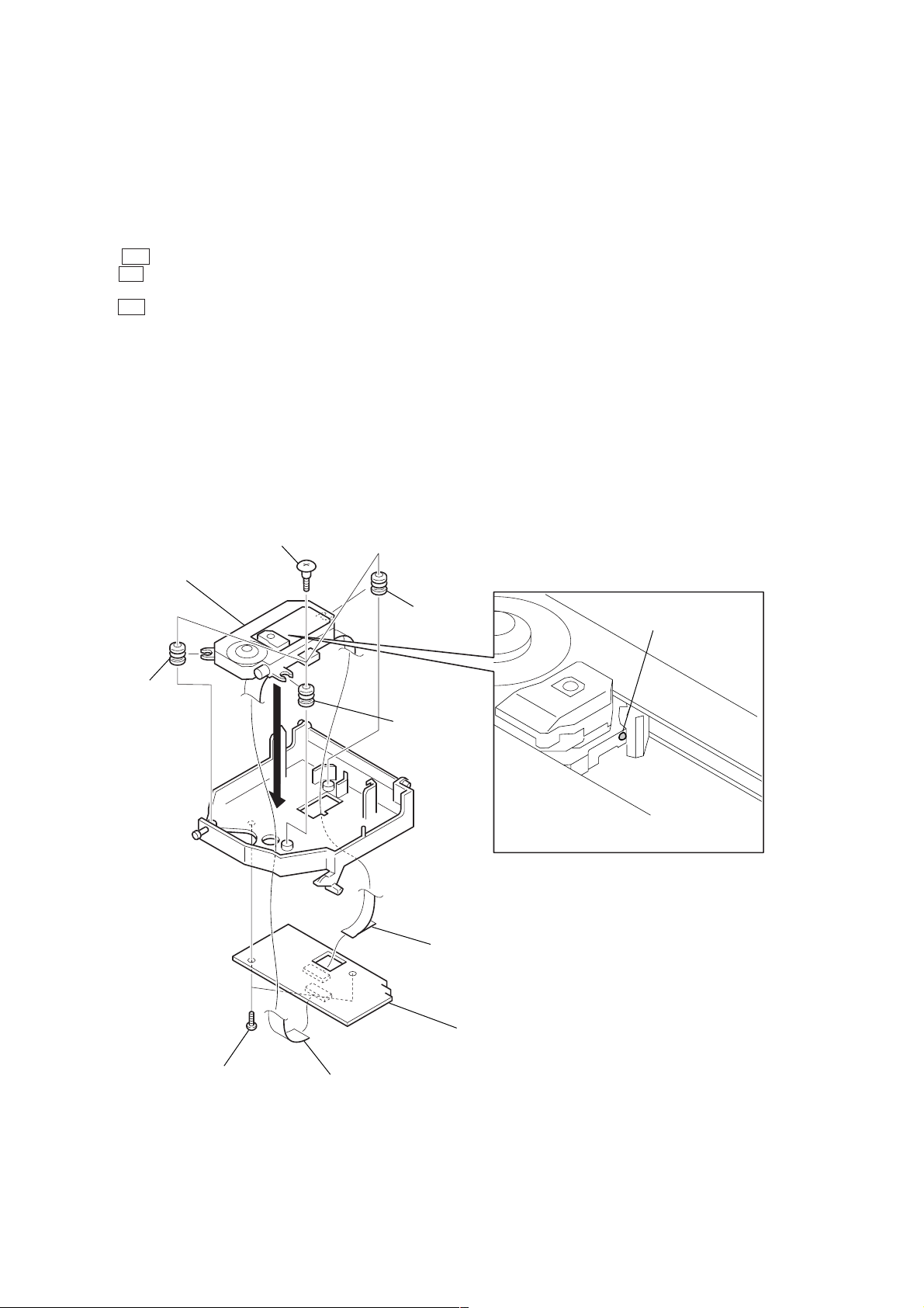
NOTES ON INSTALLING OPTICAL PICK-UP
Note: Follow the assembly procedure in the numerical order given.
3
three step screws
optical pick-up
(KHM-220AAA)
1
insulator
2
1
1
insulator
insulator
Note: Installing optical pick-up,
remove the solder for short.
6
wire (flat type) (21 core) (CN002)
4
TK board
8
Remove the solder.
5
two screws
(BVTP 2.6)
7
wire (flat type) (13 core) (CN001)
4

3. SERVICE MODE
[MC Cold Reset]
• The cold reset clears all data including preset data stored in the
RAM to initial conditions. Execute this mode when returning
the set to the customer.
Procedure:
1. Press three buttons x , DISPLAY , and DISC 5 simultaneously.
2. The fluorescent indicator tube displays “COLD RESET” and
the set is reset.
Note: To initialize DVD, refer to “Initializing set up data” in the “4. TEST
MODE 4-7. EMERGENCY HISTORY” (see page 15).
[MC Hot Reset]
• This mode resets the set with the preset data kept stored in the
memory. The hot reset mode functions same as if the power
cord is plugged in and out.
Procedure:
1. Press three buttons x , DISPLAY , and DISC 1 simultaneously .
2. The fluorescent indicator tube becomes blank instantaneously,
and the set is reset.
[CD Service Mode]
• This mode can run the CD sled motor freely . Use this mode, for
instance, when cleaning the optical pick-up.
Procedure:
1. Enter the test mode. (Refer to “4. TEST MODE” on page 7)
2. Press the [2] key of remote commander to enter the “Drive
Manual Operation”.
3. Press the [2] key of remote commander to enter the “Servo
Control”. (Refer to “2. Servo Control” on page 14)
4. Press the t (outward) or T (inward) key of remote
commander to move the sled motor.
5. To release this mode, press the ?/1 button to turn the power
OFF.
Note: • Always move the pickup to most inside track when exiting from
this mode. Otherwise, a disc will not be unloaded.
• Do not run the sled motor excessively , otherwise the gear can be
chipped.
• Remote commander: RM-SD170 (Part No.: 1-418-911-11)
[VACS ON/OFF Mode]
• This mode is used to switch ON and OFF the VACS (Variable
Attenuation Control System).
Procedure:
1. Press ?/1 button to turn the set ON.
2. Press the PUSH ENTER and x buttons simultaneously. The
message “VACS OFF” or “VACS ON” appears.
[Change-over of AM Tuner Step between 9 kHz and
10 kHz] (Except AEP, UK and Saudi Arabia models)
• A step of AM channels can be changed over between 9 kHz and
10 kHz.
Procedure:
1. Press ?/1 button to turn the set ON.
2. Select the function “TUNER”, and press TUNER/BAND
button to select the BAND “AM”.
3. Press ?/1 button to turn the set OFF.
4. Press MODE SELECT and ?/1 buttons simultaneously, and
the display of fluorescent indicator tube changes to “AM 9 k
STEP” or “AM 10 k STEP”, and thus the channel step is
changed over.
[GC Test Mode]
• This mode is used to check the software version, FL tube, LED,
keyboard and VACS.
Procedure:
1. Press ?/1 button to turn the set ON.
2. Press three buttons x , DISPLAY , and DISC 2 simultaneously.
3. LEDs and fluorescent indicator tube are all turned on.
4. When you want to enter the software version display mode,
press DISC 1 . The model number and destination are displayed.
5. Each time DISC 1 is pressed, the display changes starting
from Z-DVD version, MC version, GC version, VC version,
DVD version, ST version, TC version, TA version, TM version
and BR version in this order, and returns to the model number
and destination display.
6. When DISC 3 is pressed while the version numbers are being
displayed except model number and destination, year, month
and day of the software creation appear. When DISC 3 is
pressed again, the display returns to the software version display .
When DISC 1 is pressed while year, month and day of the
software creation are being displayed, the year, month and day
of creation of the software versions are displayed in the same
order of version display.
7. Press DISC 2 button, and the key check mode is activated.
8. In the key check mode, the fluorescent indicator tube displays
“K 0 Vo 0 Stick N”. Each time a button is pressed, “K 0”
value increases. Ho we v er , once a button is pressed, it is no longer
taken into account.
“Vo 0” value increases like 1, 2, 3 ... if rotating VOLUME
knob in “+” direction, or it decreases like 0, 9, 8 ... if rotating in
“–” direction.
Moving the stick changes the “STICK N” display.
When moved up : “STICK R”
When moved down : “STICK r ”
When moved to the left : “STICK T”
When moved to the right : “STICK t”
9. Also when DISC 3 is pressed after lighting of all LEDs and FL
tubes, value of VACS a ppears.
10. To exit from this mode, press three buttons in the same manner
as step 1, or disconnect the power cord.
5

[MC Test Mode]
• This mode is used to check operations of the respectiv e sections
of Amplifier, Tuner, CD and Tape.
Procedure:
1. Press ?/1 button to turn the set ON.
2. Press the three buttons of x , DISPLAY and DISC 3
simultaneously.
3. A message “TEST MODE” appears on the FL display tube.
4. When the joy stick is pushed up, GEQ increases to its
maximum and a message “GEQ MAX” appears.
5. When the joy stick is pushed down, GEQ decreases to its
minimum and a message “GEQ MIN” appears.
6. When the joy stick is pushed left or right, GEQ is set to flat
and a message “GEQ FLAT” appears.
7. When the VOLUME control knob is turned clockwise even
slightly, the sound volume increases to its maximum and a
message “VOLUME MAX” appears for two seconds, then the
display returns to the original display.
8. When the V OLUME control knob is turned counter-clockwise
even slightly, the sound volume decreases to its minimum and
a message “VOLUME MIN” appears for two seconds, then
the display returns to the original display.
9. In the test mode, the default-preset channel is called even when
the TUNER is selected and an attempt is made to call the preset
channel that has been stored in memory, by operating the .
and > buttons. (It means that the memory is cleared.)
10. When a tape is inserted in Deck B and recording is started, the
input source function selects VIDEO automatically.
11. When x button is pressed to stop recording, the Deck B is
selected and tape is rewound using the m button, tape is
rewound, tape is stops at around the record-starting position
and playback of the recorded portion of the tape is started. If
P A USE is inserted even once during recor ding, tape is rewound
to the position around the P AUSE position and is played back.
12. When the HI-DUB Button is press during playback of Deck
B, either normal speed or high speed can be selected by this
button.
13. Select the desired loop as follows. Press the MODE SELECT
button and press the PUSH ENTER button in the “Set Up
Mode”. Push the joy stick to right or left and press the PUSH
ENTER button in the “Direction Set Up”. Push the joy stick
to right or left and press PUSH ENTER at “Cycle”. Insert a
test tape AMS-110A or AMS-RO to Deck A.
14. Press the CD SYNCHRO button to enter the AMS test mode.
15. After a tape is rewound first, the FF AMS is checked, and the
mechanism is shut off after detecting the AMS signal twice.
16. Then the REW AMS is checked and the mechanism is shut of f
after detecting the AMS signal twice.
17. When the check is complete, a message of either OK or NG
appears.
18. When you want to exit this mode, press the ?/1 button twice.
The cold reset is enforced at the same time.
6

4. TEST MODE
4-1. GENERAL DESCRIPTION
The T est Mode allows you to make diagnosis and adjustment easily using the remote commander and monitor TV. The instructions,
diagnostic results, etc. are given on the on-screen display (OSD).
4-2. STARTING TEST MODE
Press the ?/1 button to turn the set ON, and set the function to
DVD. Press the Z 1 button to insert the DVD disc, and wait for
TOC reading is finish. Next, while pushing the x button and the
[DISPLAY] and [DISC 4] button on the main unit at the same time,
turn the regulator to the right to start Test Mode and display the
menu shown below on the TV screen. At the bottom of the menu
screen, the model name and revision number are displayed.
To execute each function, select the desired menu and press its
number on the remote commander. To exit from Test Mode, press
the ?/1 button.
Note: In the Test Mode, use the remote commander (RM-SD170)
(Part No.: 1-418-911-11).
Test Mode Menu
0. Syscon Diagnosis
1. Drive Auto Adjustment
2. Drive Manual Operation
3. Mecha Aging
4. Emergency History
5. Version Information
6. Video Level Adjustment
Exit: Power Key
_
Model : HCX-984_xxxx
Revision : 1.xxx
### Syscon Diagnosis ###
Diag All Check
No. 2 Version
2-3. ROM Check Sum
Check Sum = 2005
Press NEXT Key to Continue
Press PREV Key to Repeat
_
For the ROM Check, the check sum calculated by the Syscon is
output, and therefore you must compare it with the specified value
for confirmation.
Following the message, press [NEXT] key to go to the next item,
or [PREV] ke y to repeat the same check again. To quit the diagnosis and return to the Check Menu screen, press the x or
[ENTER] key. If an error occurred, the diagnosis is suspended
and the error code is displayed as shown below.
### Syscon Diagnosis ###
3-3. EEPROM Check
Error 03: EEPROM Write/Reed N
Address : 00000001
Write Data : 2492
Read Data : 2490
Press NEXT Key to Continue
Press PREV Key to Repeat
_
4-3. SYSCON DIAGNOSIS
The same contents as board detail check by serial interface can be
checked from the remote commander.
On the Test Mode Menu screen, press [10/0] key on the remote
commander, and the following Check Menu will be displayed.
### Syscon Diagnosis ###
Check Menu
0. Quit
1. All
2. Version
3. Peripheral
4. Servo
5. Supply
6. AV Decoder
7. Video
8. Audio
_
0. Quit
Quit the Syscon Diagnosis and return to the Test Mode Men u.
1. All
All items continuous check
This menu checks all diagnostic items continuously . Normally , all
items are checked successively one after another automatically
unless an error is found, but at a certain item that requires judgment through a visual check to the result, the following screen is
displayed for the key entry.
Press the x key to quit the diagnosis, or [PREV] key to repeat
the same item where an error occurred, or [NEXT] key to continue
the check from the item next to faulty item.
Selecting 2 and subsequent items calls the submenu screen of each
item.
For example, if “5. Supply” is selected, the following submenu
will be displayed.
### Syscon Diagnosis ###
Check Menu
No. 5 Supply
0. Quit
1. All
2. ARP Register Check
3. ARP to RAM Data Bus
4. ARP to RAM Address Bus
5. ARP RAM Check
_
0. Quit
Quit the submenu and return to the Check Menu.
1. All
All submenu items continuous check
This menu checks 2 and subsequent items successively . At the item
where visual check is required for judgment or an error occurred,
the checking is suspended and the message is output for key entry .
Normally, all items are checked successi vely one after another automatically unless an error is found.
7

Selecting 2 and subsequent items executes respective menus and
outputs the results.
For the contents of each submenu, see “Check Items List”.
General Description of Checking Method
2. Version
(2-2) Revision
ROM revision number is displayed.
Error: Not detected.
The revision number defined in the source file of ROM
(IC206) is displayed with four digits.
(2-3) ROM Check Sum
Check sum is calculated.
Error: Not detected.
The 8-bit data are added at addresses 0x000F0000 ~
0x002EFFFF of ROM (IC206) and the result is displayed
with 4-digit hexadecimal number . Error is not detected.
Compare the result with the specified value.
(2-4) Model Type
Model code is displayed.
Error: Not detected.
The model code read from EEPROM (IC201) is displayed
with 2-digit hexadecimal number.
Model Model No.
US and Canadian models 20
E, Mexican and Argentine models 22
AEP, UK and Saudi Arabia models 23
Australian model 24
Malaysia, Singapore, Hong Kong,
Thai and Taiwan models
Chinese model 26
(2-5) Region
Region code is displayed.
Error: Not detected.
The region code determined from the model code is displayed.
25
4. Servo
(4-2) Servo DSP Check
Data write → read, and accord check
Error 12: Read data discord
Data 0x9249, 0x2942, 0x4294 are written to the address
0x602 of RAM in the Servo DSP (IC701), then read and
checked.
(4-3) DSP Driver Test
Test signal data → DSP Driver
Error: Not detected.
Caution: Do not conduct this test with a mechanical deck
connected.
The maximum voltage is applied to the Servo Driver IC
(IC801, IC802). If mechanical deck is connected, the motor and optics could be damaged. Disconnect mechanical
deck following the output message, then enter specified 4or 5-digit number from the remote commander, and press
the [ENTER]. The test is conducted only when the input
data accord. Check the output level, then press the [NEXT]
to finish the test.
This test is skipped if “All” is selected.
Supplement: How to disconnect mechanical deck
Disconnect flat cables connected to the CN002 and CN003
of MB board. Also, disconnect harness from the CN013 of
MB board.
5. Supply
Caution: Do not conduct this check with a mechanical deck con-
nected.
An access is made to the stream supply and servo control IC (IC303) and external RAM (IC304) using check
data. If mechanical deck is connected, the motor and
optics could be damaged. This check is also executed
by the “All” menu item.
Supplement: How to disconnect mechanical deck
Disconnect flat cables connected to the CN002 and
CN003 of MB board. Also, disconnect harness from
the CN013 of MB board.
3. Peripheral
(3-2) Gate Array Check
Data write → read, and accord check
Error 02: Gate array write/read discord
Data 0x00~0xFF are written to the address 0xF of gate array
(IC601), then read and checked if they accord.
(3-3) EEPROM Check
Data write → read, and accord check
Error 03: EEPROM write/read discord
Data 0x9249, 0x2942, 0x4294 are written to addresses
0x00~0xFF of EEPROM (IC201), then read and checked.
Before writing, the data are saved, then after checking, they
are written to restore the contents of EEPROM.
8
(5-2) ARP Register Check
Data write → read, and accord check
Error 08: ARP register write, and read data discord
Data 0x00 to 0xFF are written to the TMAX register (address 0xC6) in ARP (IC303), then they are r ead and checked.
(5-3) ARP to RAM Data Bus
Data write → read, and accord check
Error 09: ARP ←→ RAM data bus error
Data 0x0001 to 0x8000 where one bit each is set to 1 are
written to the address 0 of RAM (IC304) connected to the
ARP (IC303) through the bus, then they are read and
checked. In case of discord, written bit pattern and read
data are displayed. If data where multiple bits are 1 are
read, the bits concerned may touch each other. Further, if
data where certain bit is always 1 or 0 regardless of written
data, the line could be disconnected or shorted.

(5-4) ARP to RAM Address Bus
Data write → other address read discord check
Error 10: ARP → RAM address bus error
Caution: Address and data display in case of an error is
different from the display of other diagnosis (de-
scribed later).
Before starting the test, all addresses of RAM (IC304) are
cleared to 0x0000.
First, 0xA55A is written to the address 0x00000, and the
address data are read and checked from addresses 0x00001
to 0x80000 while shifting 1 bit each. Next, the data at that
address is cleared, and it is written to the address 0x00001,
and read and checked in the same manner. This check is
repeated up to the address 0x80000 while shifting the address data by 1 bit each.
If data other than 0 is read at the addresses except written
address, an error is given because all addresses were already cleared to 0. In this check, the error display pattern is
different from that of other diagnosis; read data, written
address, and read address are displayed in this order. Ho wever , the message uses same template, and accordingly exchange Address and Data when reading. T he following display, for example,
6. AV Decoder
(6-2) 1930 RAM
Data write → read, and accord check
Error 13: AVD RAM read data discord
The program code data stored in ROM (IC206) are copied
to all areas of RAM (IC402, IC403) connected to the AVD
(IC401) through the bus, then they are read and checked if
they accord. Further, the same test is conducted once again
with the data where all bits are inverted between 1 and 0. If
discord is detected, faulty address, written data, and read
data are displayed following the error code 13, and the test
is suspended.
(6-3) 1930 SP
ROM → AVD RAM → Video OUT
Error: Not detected.
The data including sub picture streams in ROM (IC206)
are transferred to the RAM (IC402, IC403) in AVD (IC401),
and output as video signals from the AVD (IC401).
They are output from all video terminals (Composite, Y/C).
7. Video
### Syscon Diagnosis ###
5-4. ARP to RAM Address Bus
Error 10: ARP - RAM Address B
Address : 0000A55A
Write Data : 00000000
Read Data : 00080000
Press NEXT Key to Continue
Press PREV Key to Repeat
_
shows the data 0xA55A was read from address 0x00080000
though it was written to the address 0x00000000. This implies that these addresses are in the form of shadow. Also,
if the read data is not 0xA55A, another error will be present.
(5-5) ARP RAM Check
Data write → read, and accord check
Error 11: ARP RAM read data discord
The program code data stored in ROM are copied to all
areas of RAM (IC304) connected to the ARP (IC303)
through the bus, then they are read and checked if they accord. If the detail check was selected initially, the data are
written to all areas and read, then the same test is conducted
once again with the data where all bits are inverted between
1 and 0. If discord is detected, faulty address, written data,
and read data are displayed following the error code 11,
and the test is suspended.
(7-2) Color Bar
AVD color bar command write → Video OUT
Error: Not detected.
The command is transferred to the AVD, and the color bar
signals are output from video terminals.
They are output from all video terminals (Composite, Y/C).
8. Audio
(8-2) ARP → 1930
Error 14: ARP → 1930 video NG
15: ARP → 1930 audio NG
9

Check Items List
2) Version
(2-2) Revision
(2-3) ROM Check Sum
(2-4) Model Type
(2-5) Region
3) Peripheral
(3-2) Gate Array Check
(3-3) EEPROM Check
4) Servo
(4-2) Servo DSP Check
(4-3) DSP Driver Test
5) Supply
(5-2) ARP Register Check
(5-3) ARP to RAM Data Bus
(5-4) ARP to RAM Address Bus
(5-5) ARP RAM Check
6) AV Decoder
(6-2) 1930 RAM
(6-3) 1930 SP
7) Video
(7-2) Color Bar
Error Codes List
00: Error not detected
01: RAM write/read data discord
02: Gate array NG
03: EEPROM NG
08: ARP register read data discord
09: ARP ←→ RAM data bus error
10: ARP ←→ RAM address bus error
11: ARP RAM read data discord
12: Servo DSP NG
13: 1930 SDRAM NG
14: ARP → 1930 video NG
15: ARP → 1930 audio NG
16: 1910 UCODE download NG
17: System call error (function not supported)
18: System call error (parameter error)
19: System call error (illegal ID number)
20: System call error (time out)
90: Error occurred
91: User verification NG
92: Diagnosis cancelled
8) Audio
(8-2) ARP → 1930
(8-3) Test Tone
10

4-4. DRIVE AUTO ADJUSTMENT
1. DVD-SL (single layer)
On the T est Mode Menu screen, press [1] k e y on the remote commander, and the Adjustment Menu will be displayed.
## Drive Auto Adjustment ##
Adjustment Menu
0. ALL
1. DVD-SL
2. CD
3. DVD-DL
4. SACD
Exit: RETURN
Normally, [10/0] is selected to adjust DVD (single layer), CD,
DVD (dual layer), and SACD in this order. But, individual items
can be adjusted for the case where adjustment is suspended due to
an error. In this mode, the adjustment can be made easily through
the operation following the message displayed on the screen.
The disc used for adjustment must be the one specified for adjustment. However, for SACD disc, use the player with initial data if
the disc is not available.
0. ALL
Select [10/0] and press [ENTER] key, and the servo set data in
EEPROM will be initialized. Then, 1. DVD-SL disc, 2. CD disc,
3. DVD-DL disc, and 4. SACD disc are adjusted in this order.
Each time one disc was adjusted, it is ejected. Replace it with the
specified disc following the message. Though the message to confirm whether discs other than SACD disc are adjusted is not displayed, you can finish the adjustment if pressing the x button.
During adjustment of each disc, the measurement for disc type
judgment is made. As automatic adjustment does not judge the
disc type unlike conventional models, tak e care not to insert wrong
type discs. Also, do not give a shock during adjustment.
Select [1], insert DVD single layer disc, and press [ENTER] key,
and the adjustment will be made through the following steps, then
adjusted values will be written to the EEPROM.
DVD Single Layer Disc Adjustment Steps
1. SLED TILT Reset
2. Disc Check Memory SL
3. Wait 300 msec
4. Set Disc Type SL
5. LD ON
6. Spdl Start
7. Wait 1 sec
8. Focus Servo ON 0
9. Auto Track Offset Adjust
10. CLVA ON
11. Wait 500 msec
12. Tracking ON
13. Wait 1 sec
14. Sled ON
15. Check CLV Lock
16. Auto LFO Adjust
17. Auto Focus Offset Adjust
18. Auto Tilt Position Adjust
19. Auto Focus Gain Adjust
20. Auto Focus Offset Adjust
21. EQ Boost Adjust
22. Auto LFO Adjust
23. Auto Track Gain Adjust
Search Check
24. 32Tj Fwd
25. 32Tj Rev
26. 500Tj Fwd
27. 500Tj Rev
28. All Servo Stop
29. Eep Copy Loop Filter Offset
11

2. CD
3. DVD-DL (dual layer)
Select [2], insert CD disc, and press [ENTER] ke y , and the adjustment will be made through the following steps, then adjusted values will be written to the EEPROM.
CD Adjustment Steps
1. Sled Tilt Rest
2. Disc Check Memory CD
3. Wait 500 msec
4. Set Disc Type CD
5. LD ON
6. Spdl Start
7. Wait 500 msec
8. Focus Servo ON 0
9. Auto Track Offset Adjust
10. CLVA ON
11. Wait 500 msec
12. Tracking ON
13. (TC Display Start)
14. Wait 1 sec
15. Jitter Display Start
16. Sled ON
17. Check CLV ON
18. Auto LFO Adjust
19. Auto Focus Offset Adjust
20. Auto Focus Gain Adjust
21. Auto Focus Offset Adjust
22. Eq Boost Adjust
23. Auto LFO Adjust
24. Auto Track Gain Adjust
Search Check
25. 32Tj Fwd
26. 32Tj Rev
27. 500Tj Fwd
28. 500Tj Rev
Select [3], insert DVD dual layer disc, and press [ENTER] key,
and the adjustment will be made through the following steps, then
adjusted values will be written to the EEPROM.
DVD Dual Layer Disc Adjustment Steps
1. Sled Tilt Reset
2. Disc Check Memory DL
3. Wait 500 msec
4. Set Disc Type DL
5. LD ON
6. Spdl Start
7. Wait 1 sec, Layer 1 Adjust
8. Focus Servo ON 0
9. Auto Track Offset Adjust
10. Clva ON
11. Wait 500 msec
12. Tracking ON
13. Wait 500 msec
14. Sled ON
15. Check CLV Lock
16. Auto Loop Filter Offset Auto Focus Adjust
17. Auto Focus Gain Adjust
18. Auto Focus Offset Adjust
19. Eq Boost Adjust
20. Auto Loop Filter Offset
21. Auto Track Gain Adjust
Search Check
22. 32Tj Fwd
23. 32Tj Rev
24. 500Tj Fwd
25. 500Tj Rev
Layer 0 Adjust
26. Fj (L1 -> L0)
27. Auto Track Offset Adjust L0
29. All Servo Stop
28. Clva ON
29. Wait 500 msec
30. Tracking ON
31. Wait 500 msec
32. Sled ON
33. Check CLV Lock
34. Auto Focus Filter Offset
35. Auto Focus Adjust
36. Auto Focus Gain Adjust
37. Auto Focus Offset Adjust
38. Eq Boost Adjust
39. Auto Loop Filter Offset
40. Auto Track Gain Adjust
Search Check
41. 32Tj Fwd
42. 32Tj Rev
43. 500Tj fwd
44. 500Tj Rev
Layer Jump Check
45. Lj (L0 -> L1)
46. Lj (L1 -> L0)
47. All Servo Stop
12
 Loading...