

Sony HCD-ZX50MD Service manual
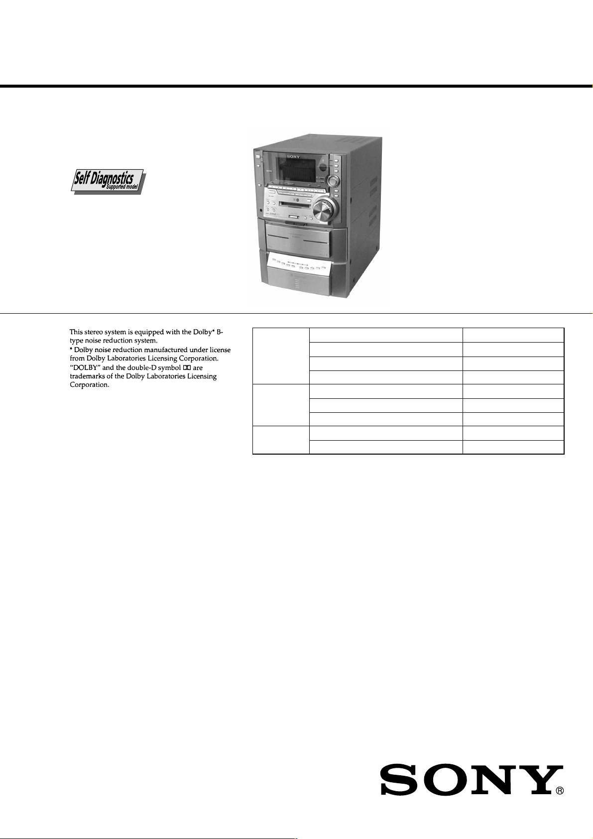
HCD-ZX50MD
SERVICE MANUAL
Ver 1.1 2001.03
HCD-ZX50MD is the tuner, deck, CD, MD and
amplifier section in DHC-ZX50MD.
Model Name Using Similar Mechanism NEW
CD
SECTION
MD
SECTION
TAPE DECK
SECTION
CD Mechanism Type CDM53F-K4BD40
Base Unit Type BU-K4BD40
Optical Pick-up Type KSM-213DHAP/Z-NP
Model Name Using Similar Mechanism MDS-JE640
MD Mechanism Type MDM-7B
Optical Pick-up Type KMS-260B/J1N
Model Name Using Similar Mechanism HCD-ZX10
T ape Transport Mechanism Type TCM-230AWR12
US Model
AEP Model
UK Model
E Model
Australian Model
Amplifier section
AUDIO POWER SPECIFICATIONS:
(US model only)
POWER OUTPUT AND TOTAL HARMONIC
DISTORTION:
with 8 ohm loads both channels driven, from 120–
10,000 Hz; rates 80 watts per channel minimum
RMS power, with no more than 10 % total
harmonic distortion from
250 milliwatts to rated output.
Total harmonics distortion Less than 0.07 %
European model:
DIN power output (rated) 60 + 60 watts
Continuous RMS power output (reference)
Music power output (reference)
(8 ohms at 1 kHz, 50 W)
(8 ohms at 1 kHz, DIN)
80 + 80 watts
(8 ohms at 1 kHz,
10 % THD)
140 + 140 watts
(8 ohms at 1 kHz,
10 % THD)
SPECIFICATIONS
Other models:
The following measured at 120/220/240 V AC, 50/60 Hz
DIN power output (rated) 115 + 115 watts
Continuous RMS power output (reference)
Inputs
VIDEO (AUDIO) IN: voltage 250 mV,
(phono jacks) impedance 47 kilohms
MIC: sensitivity 1 mV,
(mini jack) impedance 10 kilohms
(Asian model only)
Outputs
PHONES: accepts headphones of
(stereo mini jack) 8 ohms or more
FRONT SPEAKER:
US and European models:
Other models: accepts impedance of 6 to 16 ohms
SUPER WOOFER: Voltage 1 V, impedance 1 kilohms
(6 ohms at 1 kHz, DIN)
150 + 150 watts
(6 ohms at 1 kHz,
10 % THD)
accepts impedance of 8 to 16 ohms
MINI Hi-Fi COMPONENT SYSTEM
CD player section
System Compact disc and digital audio
Laser Semiconductor laser
Laser output Max. 44.6 µW*
Wavelength 780 – 790 nm
Frequency response 2 Hz – 20 kHz (±0.5 dB)
Signal-to-noise ratio More than 90 dB
Dynamic range More than 90 dB
system
(λ=780nm)
Emission duration: continuous
*This output is the value measured
at a distance of 200 mm from the
objective lens surface on the
Optical Pick-up Block with 7 mm
aperture.
— Continued on next page —
9-929-512-12
2001C0900-1
© 2001.3
Sony Corporation
Audio Entertainment Group
General Engineering Dept.
1

MD deck section
System MiniDisc digital audio system
Laser Semiconductor laser (λ=780 nm)
Laser output Max. 44.6 µW*
Sampling frequency 44.1 kHz
Frequency response 20 - 20,000 Hz
OPTICAL IN (North American model only)
(Square optical connector jacks, rear panel)
Wavelength 700 nm
Emission duration: continuous
*This output is the value measured
at a distance of 200 mm from the
objective lens surface on the
Optical Pick-up Block with a
7 mm aperture.
Tape player section
Recording system 4-track 2-channel stereo
Frequency response 40 – 13,000 Hz (±3 dB),
(DOLBY NR OFF) using Sony TYPE I cassette
Wow and flutter ±0.15 % W.Peak (IEC)
40 – 14,000 Hz (±3 dB),
using Sony TYPE II cassette
0.1 % W.RMS (NAB)
±0.2 % W.Peak (DIN)
Tuner section
FM stereo, FM/AM superheterodyne tuner
FM tuner section
Tuning range
US model: 87.5 – 108.0 MHz (100 kHz step)
Other models: 87.5 – 108.0 MHz (50 kHz step)
Antenna FM lead antenna
Antenna terminals 75 ohm unbalanced
Intermediate frequency 10.7 MHz
AM tuner section
Tuning range
US model: 530 – 1,710 kHz
European model: 531 – 1,602 kHz
Other models: 531 – 1,602 kHz
Antenna AM loop antenna
Antenna terminals External antenna terminal
Intermediate frequency 450 kHz
(with the interval set at
10 kHz)
531 – 1,710 kHz
(with the interval set at
9 kHz)
(with the interval set at
9 kHz)
(with the interval set at
9 kHz)
530 – 1,710 kHz
(with the interval set at
10 kHz)
General
Power requirements
US model: 120 V AC, 60 Hz
European model: 230 V AC, 50/60 Hz
Australian and New Zealand models:
Mexican model: 120 V AC, 60 Hz
Other models: 120 V, 220 V, 230 – 240 V AC,
Power consumption
US model: 150 watts
European model: 160 watts
Other models: 180 watts
Dimensions (w/h/d) Approx. 250 x 375 x 395 mm
Mass
US model: Approx. 11.5 kg
European model: Approx. 11.5 kg
Other models: Approx. 12.0 kg
Supplied accessories: AM loop antenna (1)
230 – 240 V AC, 50/60 Hz
50/60 Hz
Adjustable with voltage selector
FM lead antenna (1)
Remote Commander (1)
Batteries (2)
Speaker cords (2)
Front speaker pads (8)
Design and specifications are subject to change
without notice.
2
SELF-DIAGNOSIS FUNCTION
The self-diagnosis function consists of error codes for customers which are displayed automatically when errors occur, and error codes which
show the error history in the test mode during servicing. For details on how to view error codes for the customer, refer to the following box
in the instruction manual. For details on how to check error codes during servicing, refer to the following “Procedure for using the SelfDiagnosis Function (Error History Display Mode)”.
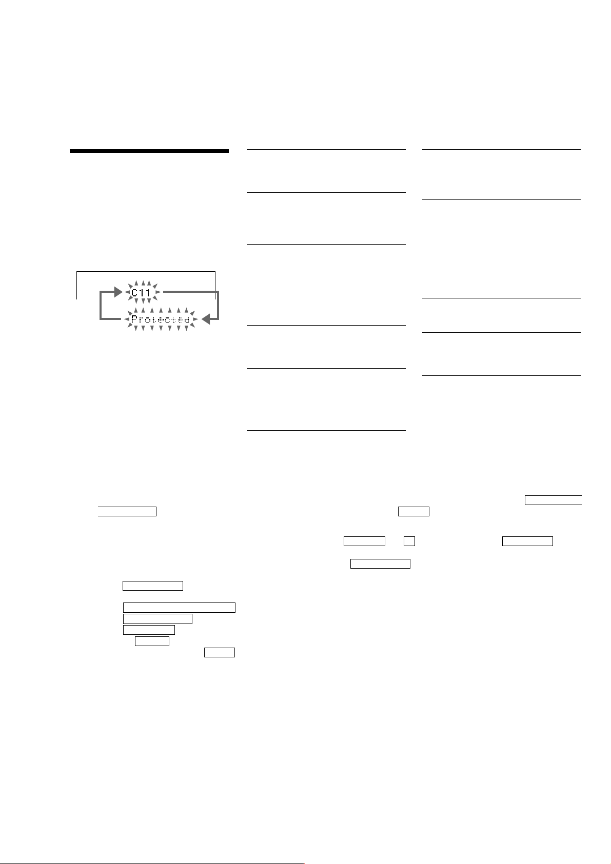
Self-diagnosis Display
This system has the Self-diagnosis display
function to let you know if there is a system
malfunction. The display shows a code made up of
three letters and a message alternately to show you
the problem. To solve the problem refer to the
following list. If any problem persists, consult
your nearest Sony dealer.
C11 / Protected
The MD is protected against erasure.
p Remove the MD and slide the tab to close the
slot (page 37).
C12 / Cannot Copy
You are attempting to record a CD with a
format that the system does not support, such as
CD-ROM.
p ––
C13 / REC Error
Recording is not possible.
p Move the system to a stable place and start
recording over from the beginning.
The MD is dirty or is scratched or the MD does
not meet the standards.
p Change the MD with another one and start
recording over from the beginning.
C13 / Read Error
The MD cannot read the disc information
correctly.
p Eject the MD once, then insert it again.
C14 / Toc Error
The MD cannot read the disc information
correctly.
p Change the MD with another one.
p Erase all the recorded contents of the MD
using the Erase function on page 52.
C41 / Cannot Copy
This unit complies with the Serial Copy
Management System (SCMS) which limits the
number of digital copies that can be made of
any given digital audio source (page 90).
C71 / Check OPT-IN
You tried to record from the digital component
when no component is connected to OPTICAL
IN jack or the digital component is not
connected correctly.
p Connect the digital component correctly to
OPTICAL IN jack with a digital optical cable.
The power of the connected digital component
is off.
p Turn on the digital component.
E0001 / MEMORY NG
The component has internal problems.
p Consult your nearest Sony dealer.
E0101 / LASER NG
There is a problem with the laser pickup.
p The laser pickup may be damaged. Consult
your nearest Sony dealer.
Procedure for using the Self-Diagnosis Function (Error History Display Mode).
Note: Perform the self-diagnosis function in the “error history display mode” in the test mode. The following describes the least required
procedure. Be careful not to enter other modes by mistake. If other modes are entered accidentally, press the NAME EDIT/
CHARACTER button while REC IT is lit, and when REC IT goes off, press the MD Z button to exit the mode.
1. In the power ON state, set the function to MD, and while pressing the DISPLAY and x buttons together , press V-GROOVE . While
the test mode is set. “[Check]” will be displayed.
2. Move the multi-stick left and right to display “[Service]” and press the PUSH ENTER button.
3. Move the multi-stick left and right to display “Err Display”.
4. Press the PUSH ENTER button to enter the error history mode. “op rec tm” will be displayed.
5. Select the item to be displayed or executed using the multi-stick.
6. Press the NAME EDIT/CHARACTER button so that REC IT lights up.
7. Press the MD REC MODE button to display the selected item.
8. Press the REC MODE button another time to return to step 4.
9. Pressing the CLEAR button when REC IT is lit displays “Err Display” and exits the error history display mode.
10. To exit the test mode, press the MD Z button while REC IT is off. This sets the standby state and ends the test mode.
3
ITEMS OF ERROR HISTORY MODE ITEMS AND CONTENTS
Selecting the Test Mode
Display
op rec tm
op play tm
spdl rp tm
retry err
total err
err history
retry adrs
History
Displays the total recording time.
When the total recording time is more than 1 minute, displays the hour and minute
When less than 1 minute, displays “Under 1 min”
The display time is the time the laser is set to high power, which is about 1/4 of the actual recording time.
Displays the total playback time.
When the total playback time is more than 1 minute, displays the hour and minute
When less than 1 minute, displays “Under 1 min”
Displays the total rotating time of the spindle motor.
When the total rotating time is more than 1 minute, displays the hour and minute
When less than 1 minute, displays “Under 1 min”
Displays the total number of retry errors during recording and playback
Displays “r xx p yy”. xx is the number of errors during recording. yy is the number of errors during playback.
This is displayed in hexadecimal from 00 to FF.
Displays the total number of errors
Displays “total xx”. This is displayed in hexadecimal from 00 to FF.
Displays the past ten errors.
Displays “0x ErrCd@@”.
X is the history number. The younger the number , the more recent is the history (00 is the latest). @@ is the error
code.
Select the error history number using the Multi stick.
Displays the past five retry addresses.
Displays “xx ADRS yyyy”, xx is the history number, yyyy is the cluster with the retry error.
Select the error history number using the Multi stick.
er refresh
op change
spdl change
Mode for erasing the error and retry address histories
Procedure
1. Press the MD REC MODE button while “REC IT” is lit when displayed as “er refresh”.
2. Press the PUSH ENTER button when the display changes to “er refresh?”.
When “complete!” is displayed, it means erasure has completed.
Be sure to check the following after executing this mode.
*Data has been erased.
*Perform recording and playback, and check that the mechanism is normal.
Mode for erasing the total time of op rec tm, op play tm.
These histories are based on the time of replacement of the optical pick-up. If the optical pick-up has been
replaced, perform this procedure and erase the history.
Procedure
1. Press the MD REC MODE button while “REC IT” is lit when displayed as “op change”.
2. Press the PUSH ENTER button when the display changes to “op change?”.
When “Complete!” is displayed, it means erasure has completed.
Mode for erasing the total spdl rp tm time
These histories are based on the time of replacement of the spindle motor. If the spindle motor has been replaced,
perform this procedure and erase the history.
Procedure
1. Press the MD REC MODE button while “REC IT” is lit when displayed as “spdl change”
2. Press the PUSH ENTER button when the display changes to “spdl change?”
When “Complete!” is displayed, it means erasure has completed.
4

Table of Error Codes
Error Code
10
12
20
21
22
23
24
30
31
40
41
42
43
50
51
Description
Could not load
Loading switches combined incorrectly
Timed out without reading the top of PTOC
Could read top of PTOC, but detected error
Timed out without accessing UTOC
Timed out without reading UTOC
Error in UTOC
Could not start playback
Error in sector
Retry cause generated during normal recording
Retried in DRAM overflow
Retry occurred during TOC writing
Retry aborted during S.F editing
Other than access processing, and could not read address.
Focus NG occurred and overran.
5

TABLE OF CONTENTS
1. SERVICING NOTES ............................................. 7
2. GENERAL ........................................................................ 15
3. DISASSEMBLY
3-1. Case .................................................................................. 18
3-2. Front Panel Section .......................................................... 18
3-3. MD Mechanism Section
T ape Mechanism Deck Section (TCM-230AWR12)........19
3-4. Back Panel Section ........................................................... 19
3-5. MD Mechanism Deck Section (MDM-7B)...................... 20
3-6. Main Board, Front AMP Board ........................................ 20
3-7. CD Base Unit (BU-K4BD40)........................................... 21
3-8. CD Mechanism Deck Section (CDM53F-K4BD40)........ 21
3-9. Fitting Base (Guide) Assy, Bracket (Chassis) and
Fitting Base (Magnet) Assy.............................................. 22
3-10. Tray (Sub).........................................................................22
3-11. Chassis (Mold B) Section, Stocker Section and
Slider (Selection) ............................................................. 23
3-12. Gears Installation.............................................................. 23
3-13. Slider (Selection) Installation........................................... 24
3-14. Stocker Section Installation.............................................. 24
3-15. Chassis (Mold B) Section Installation.............................. 25
3-16. BD Board.......................................................................... 25
4. TEST MODE...................................................................... 26
5. MECHANICAL ADJUSTMENTS............................... 35
6. ELECTRICAL ADJUSTMENTS................................. 35
7. DIAGRAMS
7-1. Circuit Boards Location ...................................................... 51
7-2. Block Diagrams
• CD Section....................................................................... 54
• MD Section ...................................................................... 55
• SYSCON/SER VO Section............................................... 56
• MAIN Section.................................................................. 57
7-3. Printed Wiring Board – Deck Section –.............................. 58
7-4. Schematic Diagram – Deck Section – ................................ 59
7-5. Printed Wiring Board – CD Section –................................. 60
7-6. Schematic Diagram – CD Section – ................................... 61
7-7. Printed Wiring Board – MD Section –................................ 62
7-8. Schematic Diagram – MD (1/2) Section –.......................... 63
7-9. Schematic Diagram – MD (2/2) Section –.......................... 64
7-10. Printed Wiring Board – Main Section –........................... 65
7-11. Schematic Diagram – Main (1/4) Section – ..................... 66
7-12. Schematic Diagram – Main (2/4) Section – ..................... 67
7-13. Schematic Diagram – Main (3/4) Section – ..................... 68
7-14. Schematic Diagram – Main (4/4) Section – ..................... 69
7-15. Printed Wiring Board – Digital (Side A) Section –.......... 70
7-16. Printed Wiring Board – Digital (Side B) Section –.......... 71
7-17. Schematic Diagram – Digital (1/2) Section – .................. 72
7-18. Schematic Diagram – Digital (2/2) Section – .................. 73
7-19. Printed Wiring Board
– AMP (US, AEP, UK, G, AED, CIS model) Section – .. 74
7-20. Schematic Diagram
– AMP (US, AEP, UK, G, AED, CIS model) Section – .. 75
7-21. Printed Wiring Board – AMP (E, MX, AR, HK,
MY, SP, KR, AUS model) Section – ................................ 76
7-22. Schematic Diagram – AMP (E, MX, AR, HK,
MY, SP, KR, AUS model) Section – ................................ 77
7-23. Printed Wiring Board – Panel Section –........................... 78
7-24. Schematic Diagram – Panel Section – ............................. 79
7-25. Printed Wiring Board – Switch Section – ........................ 80
7-26. Schematic Diagram – Switch Section – ........................... 81
7-27. Printed Wiring Board – CD Mechanism Section – .......... 82
7-28. Schematic Diagram – CD Mechanism Section – ............. 83
7-29. Printed Wiring Board – Leaf SW Section – ..................... 84
7-30. Schematic Diagram – Leaf SW Section –........................ 84
7-31. Printed Wiring Board – MIC Section –............................ 85
7-32. Schematic Diagram – MIC Section –............................... 85
7-33. Printed Wiring Board – Power Supply (US, AEP, UK,
G, AED, CIS model) Section – ........................................ 86
7-34. Schematic Diagram – Power Supply (US, AEP, UK,
G, AED, CIS model) Section – ........................................ 87
7-35. Printed Wiring Board – Power Supply (E, MX, AR, HK,
MY, SP, KR, AUS model) Section – ................................ 88
7-36. Schematic Diagram – Power Supply (E, MX, AR, HK,
MY, SP, KR, AUS model) Section – ................................ 89
7-37. IC Block Diagrams........................................................... 90
7-38. IC Pin Functions............................................................... 94
8. EXPLODED VIEWS
8-1. Back Panel Section ......................................................... 106
8-2. Front Panel Section ........................................................ 107
8-3. Chassis Section............................................................... 108
8-4. CD Mechanism Deck Section-1 ..................................... 109
8-5. CD Mechanism Deck Section-2 ..................................... 110
8-6. Base Unit Section ........................................................... 111
8-7. Tape Mechanism Deck Section-1 ................................... 112
8-8. Tape Mechanism Deck Section-2 ................................... 113
8-9. MD Mechanism Section-1.............................................. 114
8-10. MD Mechanism Section-2.............................................. 115
9. ELECTRICAL PARTS LIST ...................................... 117
MODEL IDENTIFICATION
— BACK PANEL —
6
Parts No.
MODEL
US model
AEP, UK, G, AED, CIS model
MY, SP model
E model
AR model
HK model
MX model
AUS model
KR model
• Abbreviation
G : German model
AED : North European model
MX : Mexican model
AR : Argentine model
HK : Hong Kong model
MY : Malaysia model
SP : Singapore model
KR : Korean model
AUS : Australian model
PARTS No.
4-227-556-0s
4-227-556-2s
4-227-556-3s
4-227-556-4s
4-227-556-5s
4-227-556-6s
4-227-556-7s
4-227-556-8s
4-227-556-9s
0.15µF
To Exposed Metal
Parts on Set
1.5kΩ
AC
voltmeter
(0.75V)
Earth Ground
SECTION 1
SERVICE NOTES
NOTES ON HANDLING THE OPTICAL PICK-UP
BLOCK OR BASE UNIT
The laser diode in the optical pick-up block may suffer electrostatic
break-down because of the potential difference generated by the
charged electrostatic load, etc. on clothing and the human body.
During repair, pay attention to electrostatic break-down and also
use the procedure in the printed matter which is included in the
repair parts.
The flexible board is easily damaged and should be handled with
care.
FOR CD
NOTES ON LASER DIODE EMISSION CHECK
The laser beam on this model is concentrated so as to be focused on
the disc reflective surface by the objective lens in the optical pickup block. Therefore, when checking the laser diode emission,
observe from more than 30 cm away from the objective lens.
FOR MD
NOTES ON LASER DIODE EMISSION CHECK
Never look into the laser diode emission from right above when
checking it for adjustment. It is feared that you will lose your sight.
Laser component in this product is capable
of emitting radiation exceeding the limit for
Class 1.
SAFETY CHECK-OUT
(US model only)
After correcting the original service problem, perform the
following safety checks before releasing the set to the customer:
Check the antenna terminals, metal trim, “metallized” knobs, screws,
and all other exposed metal parts for AC leakage. Check leakage as
described below.
LEAKAGE
The AC leakage from any exposed metal part to earth ground and
from all exposed metal parts to any exposed metal part having a
return to chassis, must not exceed 0.5 mA (500 microampers).
Leakage current can be measured by any one of three methods.
1. A commercial leakage tester , such as the Simpson 229 or RCA
WT -540A. Follow the manufacturers’ instructions to use these
instruments.
2. A battery-operated AC milliammeter. The Data Precision 245
digital multimeter is suitable for this job.
3. Measuring the voltage drop across a resistor by means of a
VOM or battery-operated AC voltmeter . The “limit” indication
is 0.75 V, so analog meters must have an accurate low-voltage
scale. The Simpson 250 and Sanwa SH-63Trd are examples of
a passive VOM that is suitable. Nearly all battery operated
digital multimeters that have a 2V AC range are suitable. (See
Fig. A)
This appliance is classified as a CLASS 1 LASER product. The
CLASS 1 LASER PRODUCT MARKING is located on the rear
exterior.
CAUTION
Use of controls or adjustments or performance of procedures
other than those specified herein may result in hazardous radiation
exposure.
Notes on chip component replacement
• Never reuse a disconnected chip component.
• Notice that the minus side of a tantalum capacitor may be
damaged by heat.
Flexible Circuit Board Repairing
• Keep the temperature of soldering iron around 270˚C
during repairing.
• Do not touch the soldering iron on the same conductor of the
circuit board (within 3 times).
• Be careful not to apply force on the conductor when soldering
or unsoldering.
This caution
label is located
inside the unit.
Fig. A. Using an AC voltmeter to check AC leakage.
SAFETY-RELATED COMPONENT WARNING!!
COMPONENTS IDENTIFIED BY MARK 0 OR DOTTED LINE WITH
MARK 0 ON THE SCHEMATIC DIAGRAMS AND IN THE PARTS
LIST ARE CRITICAL TO SAFE OPERATION. REPLACE THESE
COMPONENTS WITH SONY PARTS WHOSE PART NUMBERS
APPEAR AS SHOWN IN THIS MANUAL OR IN SUPPLEMENTS
PUBLISHED BY SONY .
7
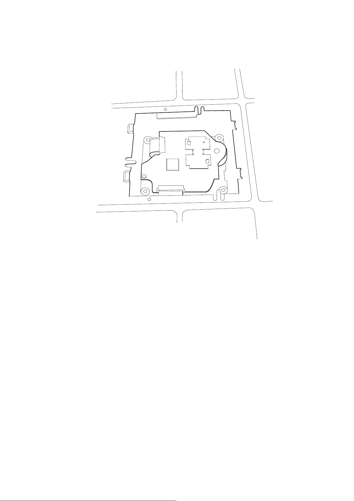
SERVICE POSITION
Jig (A-2501-076-A)
CN701
CN503
• CD MECHANISM BLOCK
Jig (A-2501-165-A)
Jig (A-2501-167-A)
Jig (A-2501-011-A)
8
• BD (CD) BOARD
To repair the BD (CD) board,remove the bottom plate.
Bottom view
9
JIG FOR CHECKING BD (MD) BOARD WAVEFORM
B
The special jig (J-2501-196-A) is useful for checking the waveform of the BD (MD) board. The names of terminals and the checking items
to be performed are shown as follows.
GND : Ground
I+3V : For measuring IOP (Check the deterioration of the optical pick-up laser)
IOP : For measuring IOP (Check the deterioration of the optical pick-up laser)
TE : TRK error signal (Traverse adjustment)
VC : Reference level for checking the signal
RF : RF signal (Check jitter)
FE : Focus error signal
I+3V
GND
FE
RF
IOP
TE
VC
I+3V
IOP
GND
TE
FE
VC
RF
CN105
1
I+3V
Iop
GND
TE
FE
VC
RF
7
for
MDM-7
10

Iop DATA RECORDING AND DISPLAY WHEN OPTICAL PICK-UP AND NON-VOLATILE MEMORY (IC195 OF
BD (MD) BOARD) ARE REPLACED
The Iop value labeled on the optical pick-up can be recorded in the non-volatile memory. By recording the value, it will eliminate the need to
look at the value on the label of the optical pick-up. When replacing the optical pick-up or non-volatile memory (IC195 of BD (MD) board),
record the Iop value on the optical pick-up according to the following procedure.
Record Precedure:
1. In the power ON state, set the function to MD, and while pressing the DISPLA Y and x buttons together, press V-GROOVE .
2. Move the Multi stick to display “[Service]”, and press the PUSH ENTER button.
3. Move the Multi stick to display “Iop Write” (C05), and press the PUSH ENTER button.
4. The display becomes “Ref=@@@.@” (@ is an arbitrary number) and the numbers which can be changed will blink.
5. Input the Iop value written on the optical pick-up.
To select the number : Move the Multi stick.
To select the digit : Press the MD REC MODE button while REC IT is lit.
6. When the PUSH ENTER button is pressed, the display becomes “Measu=@@@.@” (@ is an arbitrary number).
7. As the adjustment results are recorded for the 6 value. Leave it as it is and press the PUSH ENTER button.
8. “Complete!” will be displayed momentarily. The value will be recorded in the non-volatile memory and the display will become “Iop
Write” (C05).
Display Precedure:
1. In the power ON state, set the function to MD, and while pressing the DISPLA Y and x buttons together, press V-GROOVE .
2. Move the Multi stick to display “[Service]”, and press the PUSH ENTER button.
3. Move the Multi stick to display “Iop Read” (C26).
4. “@@.@/##.#” is displayed and the recorded contents are displayed.
@@.@ : indicates the Iop value labeled on the optical pick-up.
##.# : indicates the Iop value after adjustment
5. To end, press the NAME EDIT/CHARACTER button while REC IT is lit, or press the MD REC MODE button to display “Iop Read”
(C26).
11

CHECKS PRIOR TO PARTS REPLACEMENT AND ADJUSTMENTS
Before performing repairs, perform the following checks to determine the faulty locations up to a certain extent.
Details of the procedures are described in “6 Electrical Adjustments”.
• 6-6-2. Laser power check (see page 43)
• 6-6-3. Iop Compare (see page 43)
• 6-6-4. Auto Check (see page 44)
Note:
The criteria for determination above is intended merely to determine if satisfactory or not, and does not serve as the specified value for
adjustments.
When performing adjustments, use the specified values for adjustments.
FORCED RESET
The system microprocessor can be reset in the following procedure.
Use these procedure when the unit cannot be operated normally due to the overrunning of the microprocessor, etc.
Procedure :
1. Disconnect the AC outlet.
2. Momentary short between BT901 pin 3 and BT901 pin # by lead wire.
3. Momentary short between C416 pin 3 and C416 pin # by lead wire.
[MAIN BOARD]
BT901
+
IC401
+
C416
12
RETRY CAUSE DISPLAY MODE
• In this test mode, the causes for retry of the unit during recording can be displayed on the fluorescent indicator tube. During playback, the
“track mode” for obtaining track information will be set.
This is useful for locating the faulty part of the unit.
• The following will be displayed :
During recording and stop: Retry cause, number of retries, and number of retry errors.
During playback : Information such as type of disc played, part played, copyright.
These are displayed in hexadecimal.
Procedure:
1. Press the x button and DISPLAY button, CINEMA SPACE button.
2. When the mode is set, “RTs 00c 00e 000” is displayed.
3. Press the MD REC button to start recording. Then press the MD u button and start recording.
4. To check the “track mode”, press the MD u button to start play.
5. To exit the test mode, press the @/1 button, and turn OFF the power . When “TOC” disappears, disconnect the power plug from the outlet.
If the test mode cannot be exited, refer to “Forced Reset” on page 12 .
Fig. 1 Reading the Test Mode Display
(During recording and stop)
(During playback)
RTs@@c##c***
Fluorescent display tube display
@@ : Cause of retry
## : Number of retries
*** : Number of retry errors
Fig. 2 Reading the Test Mode Display
Reading the Retry Cause Display
Higher Bits Lower Bits
Hexadecimal
Bit
Binary
84218421
b7 b6 b5 b4 b3 b2 b1 b0
00000001
00000010
00000100
00001000
00010000
00100000
01000000
10000000
Hexa-
decimal
01
02
04
08
10
20
40
80
@@####**$$
Fluorescent display tube display
@@ : Parts No. (name of area named on TOC)
## : Cluster
** : Sector
$$ : Track mode (Track information such as copyright
information of each part)
Cause of Retry Occurring conditions
shock
ader5
Discontinuous address
DIN unlock
FCS incorrect
IVR rec error
CLV unlock
Access fault
When track jump (shock) is detected
When ADER was counted more than five times continuously
When ADIP address is not continuous
When DIN unlock is detected
When not in focus
When ABCD signal level exceeds the specified range
When CLV is unlocked
When access operation is not performed normally
Address (Physical address on disc)
}
Reading the Display:
Convert the hexadecimal display into binary display . If more than two causes, they will be added.
Example
When 42 is displayed:
Higher bit : 4 = 0100 t b6
Lower bit : 2 = 0010 t b1
In this case, the retry cause is combined of “CLV unlock” and “ader5”.
When A2 is displayed:
Higher bit : A = 1010 t b7+b5
Lower bit : 2 = 0010 t b2
The retry cause in this case is combined of “access fault”, “IVR rec error”, and “ader5”.
13
Reading the Track Mode Display
Higher Bits Lower Bits
Hexadecimal
Bit
Binary
Reading the Display:
Convert the hexadecimal display into binary display . If more than two causes, they will be added.
Example When 84 is displayed:
Higher bit : 8 = 1000 t b7
Lower bit : 4 = 0100 t b2
In this case, as b2 and b7 are 1 and others are 0, it can be determined that the retry cause is combined of “emphasis OFF”, “monaural”,
“original”, “copyright exists”, and “write allowed”.
Example When 07 is displayed:
Higher bit : 0 = 1000 t All 0
Lower bit : 7 = 0111 t b0+b1+b2
In this case, as b0, b1, and b2 are 1 and others are 0, it can be determined that the retry cause is combined of “emphasis ON”, “stereo”,
“original”, “copyright exists”, and “write prohibited”.
84218421
b7 b6 b5 b4 b3 b2 b1 b0
00000001
00000010
00000100
00001000
00010000
00100000
01000000
10000000
Hexa-
decimal
01
02
04
08
10
20
40
80
When 0 When 1
Emphasis OFF
Monaural
This is 2-bit display. Normally 01.
01:Normal audio. Others:Invalid
Audio (Normal)
Original
Copyright
Write prohibited
Details
Emphasis ON
Stereo
Invalid
Digital copy
No copyright
Write allowed
Hexadecimal t Binary Conversion Table
Hexadecimal Binary Hexadecimal Binary
0
1
2
3
4
5
6
7
0000
0001
0010
0011
0100
0101
0110
0111
8
9
A
B
C
D
E
F
1000
1001
1010
1011
1100
1101
1110
1111
14
SECTION 2
GENERAL
wh
wg
wf
wd
12
ws
wa
9
qa
qs
qd
qf
qg
qh
qj
qk
ql
w;
rd
rs
ra
r;
el
ek
ej
eh
wj wk wl e;3 4 5 678 0
ea
es
ed
ef
eg
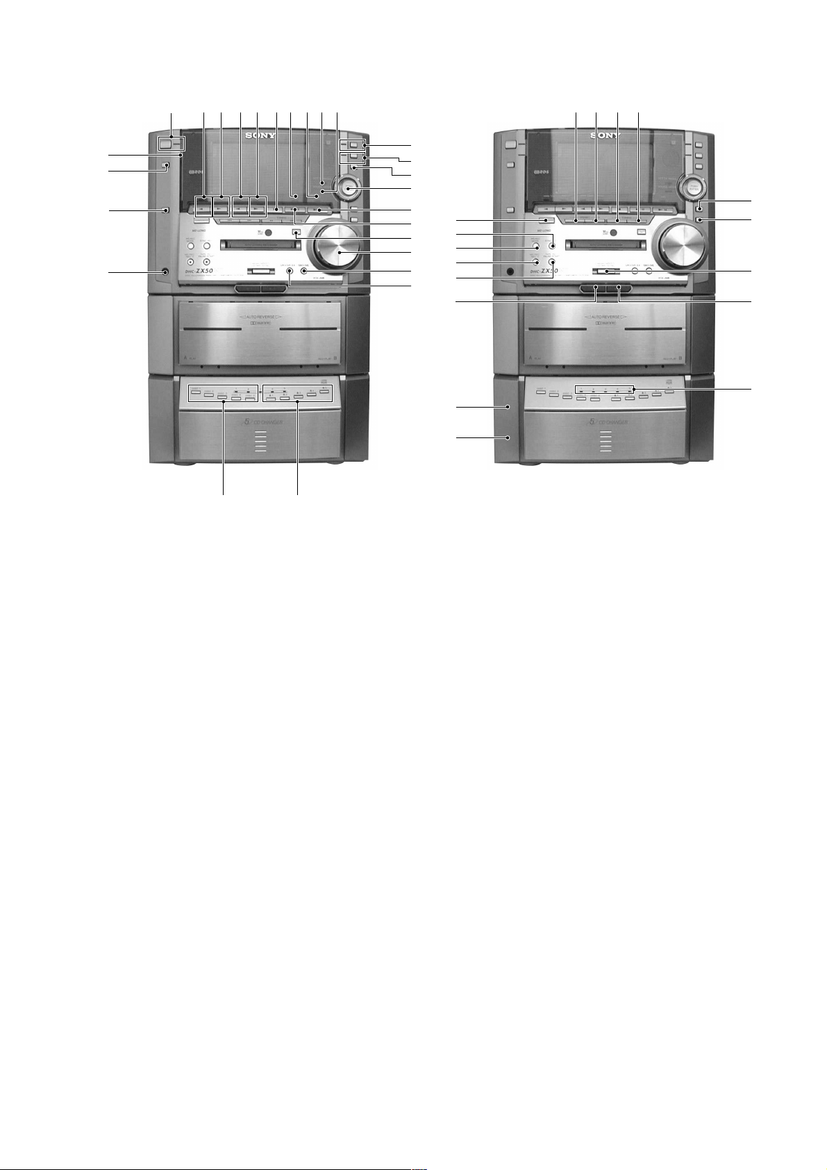
1 ?/1 button and indicator
2 T APE A h button and indicator
3 T APE A H button and indicator
4 TAPE B h button and indicator
5 TAPE B H button and indicator
6 x button
7 CD indicator
8 MD indicator
9 SET UP MODE indicator
0 SOUND MODE indicator
qa CINEMA SPACE button and indicator
qs V-GROOVE button and indicator
qd MODE SELECT button
qf PUSH ENTER button/Multi stick
qg MD u button
qh CD u button
qj MD Z button
qk VOLUME knob
ql GROOVE button
w; GROOVE EX button
wa Z 1 to Z 5 buttons
ws DISC 1 to DISC 5 buttons
wd PHONES jack
wf FUNCTION button
wg DISPLAY button
wh TIMER SELECT indicator
wj . button
wk > button
wl m button
e; M button
ea NAME EDIT/CHARACTER button
es CLEAR button
ed HIGH SPEED CD-MD SYNC button
ef TAPE B Z button
eg DISC 1 to DISC 5 indicator
eh MIC jack (HK,MY,SP,KR model)
ej MIC VOL knob (HK,MY,SP,KR model)
ek T APE A Z button
el TAPE REC PAUSE/START button
r; MD REC button
ra MD REC MODE button
rs SYNC REC button
rd TUNER/BAND button
15
This section is extracted from
instruction manual.
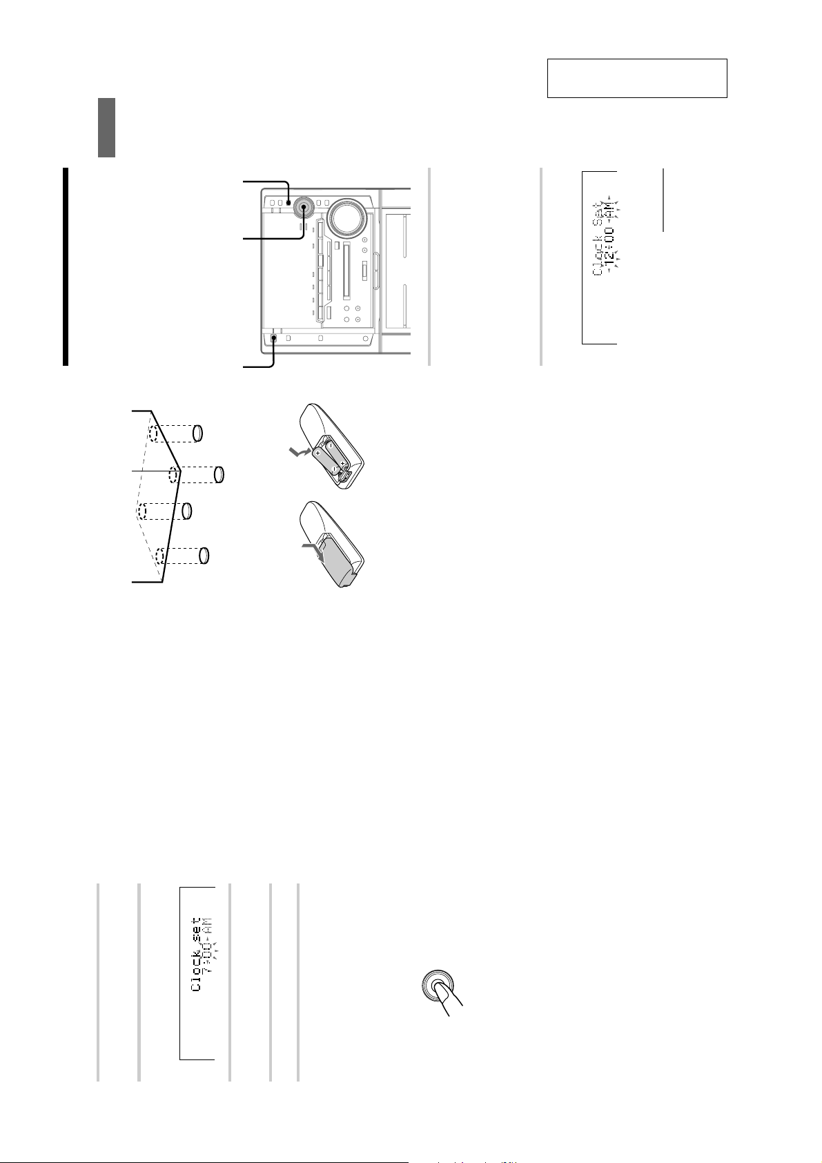
Getting Started
1
2,3,4,5,6
Step 2: Setting the time
You must set the time before using the timer
functions.
The clock is on a 24-hour system for the European
model, and on a 12-hour system for other models.
For illustration purposes, the 12-hour system
model is used.
?/1
(Power)
set Power Saving Mode off, or follow the
steps on the following page (“To change the
When the system is in the Power Saving
Press MODE SELECT when the system
is turned off.
“Clock Set ?” appears.
1
time”) after turning the power on.
Mode, “Clock Set ?” will not appear. Either
Press PUSH ENTER.
The hour indication flashes.
2
7
continued
To attach the front speaker pads
Attach the supplied front speaker pads to the
bottom of the speakers to stabilize the speakers
and prevent them from slipping.
Up Mode”, then press PUSH ENTER.
to select “Timer Set Up ?”, then press PUSH
ENTER.
to select “Clock Set ?”, then press PUSH
To change the time
The previous explanation shows you how to set
the time while the power is off. To change the
time while the power is on, do the following:
1 Press MODE SELECT repeatedly to select “Set
2 Move the multi stick toward b or B repeatedly
ENTER.
3 Move the multi stick toward b or B repeatedly
Inserting two size AA (R6)
The clock settings are canceled when you disconnect
4 Perform steps 3 through 6 on the left.
Note
batteries into the remote
the power cord or if a power failure occurs.
Tip
With normal use, the batteries should last for about
appears in the display.
“LOCK” appears in the display.
six months. When the remote no longer operates the
system, replace both batteries with new ones.
Note
If you do not use the remote for a long period of time,
remove the batteries to avoid possible damage from
battery leakage.
When carrying this system
Do the following to protect the CD mechanism.
Make sure that all discs are removed from the
Right (B)Left (b)
unit.
2 Hold down V-GROOVE and press ?/1 so that
1 Press FUNCTION repeatedly until “CD”
Move the multi stick toward v or V
repeatedly to set the hour.
(continued)
Step 2: Setting the time
3
16
Move the multi stick toward B.
The minute indication flashes.
4
Move the multi stick toward v or V
5
repeatedly to set the minute.
Press PUSH ENTER.
6
To cancel the menu operation
Press MODE SELECT.
Tips
• Refer to the illustration to use the multi stick. Place
PUSH
ENTER
Up (v)
your finger on the center of the multi stick and
move in the direction you want (up/down or left/
right shown v/V or b/B in this manual).
Down (V)
• If you’ve made a mistake, start over from step 1.
8
*
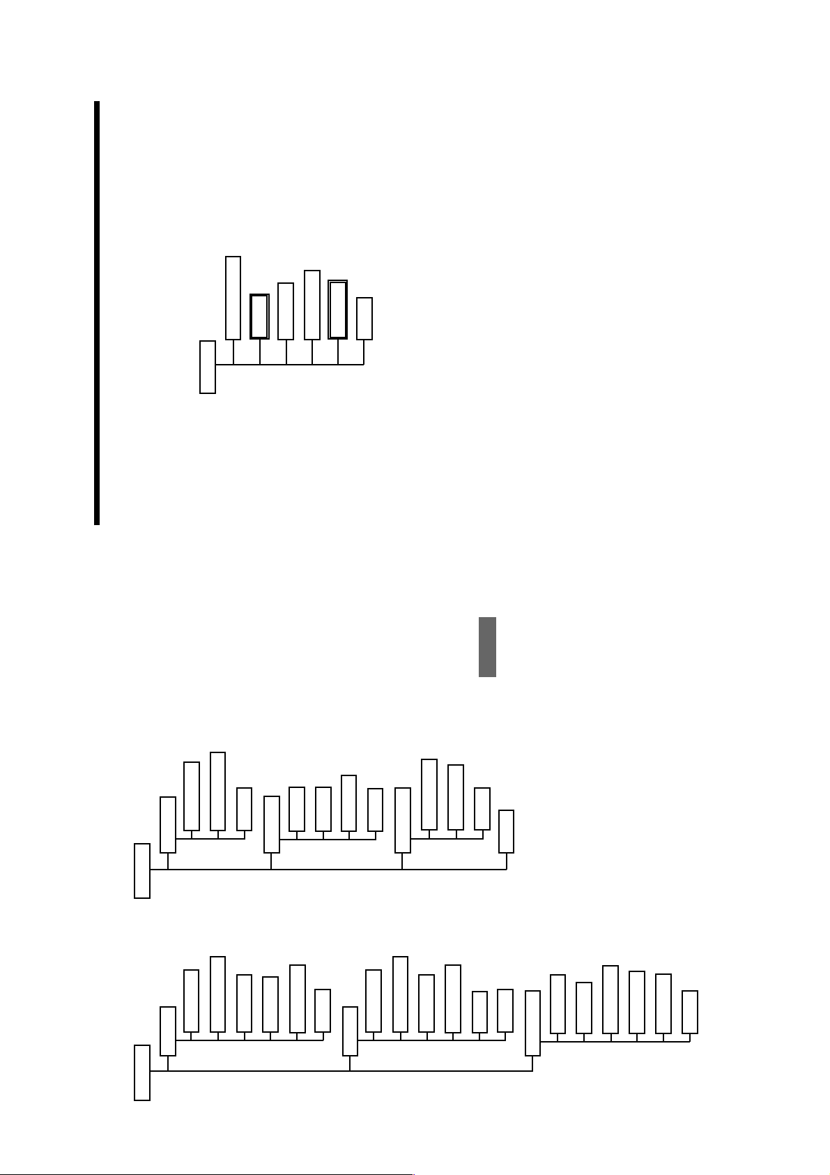
File Select (70, 74)
Effect OnpOff/OffpOn (70)
Sound Mode
Items in “Sound Mode” and “Set Up Mode”
The numbers in parenthesis denotes the page number for the item.
P File Memory (74)
Cinema Space (72)
Equalizer Control (73)
Mode End
buttons on the front panel or on the remote.
• To cancel the menu operation, press MODE SELECT.
• The items with asterisk (*) cannot be selected depending on the situation.
• The items in double box are not in the menu. In order to select the doublebox items, press the corresponding
• Select “Mode End” to finish the menu operation.
Additional Information
100
101
TAPE Set Up ?
Set Up Mode
*
CD Set Up ?
Set Up Mode
Direction Set Up ? (18, 23, 64, 66)
Repeat Set Up ? (26)
Mode End
DOLBY NR Set Up ? (16, 19, 24, 65)
1)
CD Edit Start ? (68)
Play Mode Set Up ? (27, 30)
Clock Set ? (8)
Timer Set Up ?
*
2)
PGM Check Clear (29, 67)
Program Set ? (28, 38, 66)
*
*
Mode End
Timer Select ? (80, 82)
Timer Set ? (80, 82)
*
Mode End
Repeat Set Up ? (33)
MD Set Up ?
Mode End
Dimmer Set Up ? (71)
Spectrum Set Up ? (71)
Display Set Up ?
*
3)
Program Set ? (34)
Play Mode Set Up ? (34, 36)
PGM Check Clear (35, 36)
Mode End
Mode End
MD Edit ? (41, 42, 44–63)
*
*
TUNER Set Up ?
*
Stereo Mono ? (21)
*
TUNER Memory ? (9)
PTY Select ? (76)
TUNER Erase ? (10)
*
TUNER Name? (78)
Mode End
Cannot be selected during CD playback.
1)
Cannot be selected during CD program playback.
Cannot be selected during MD playback.
2)
3)
17
SECTION 3
)
DISASSEMBLY
Note : Follow the disassembly procedure in the numerical order given.
3-1. CASE
4 three screws
(case 3 TP2)
1 three screws
(BVTT 3 × 8)
5 Remove the case
in the arrow direction.
2 two screws
(BVTT 3 × 8)
3 three screws
(case 3 TP2)
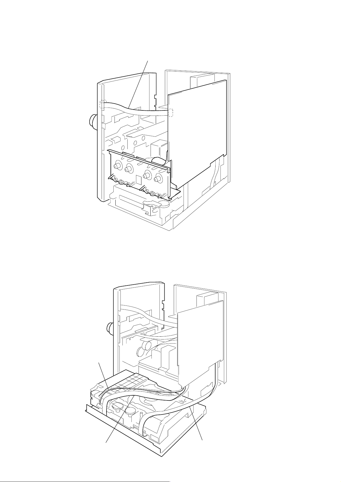
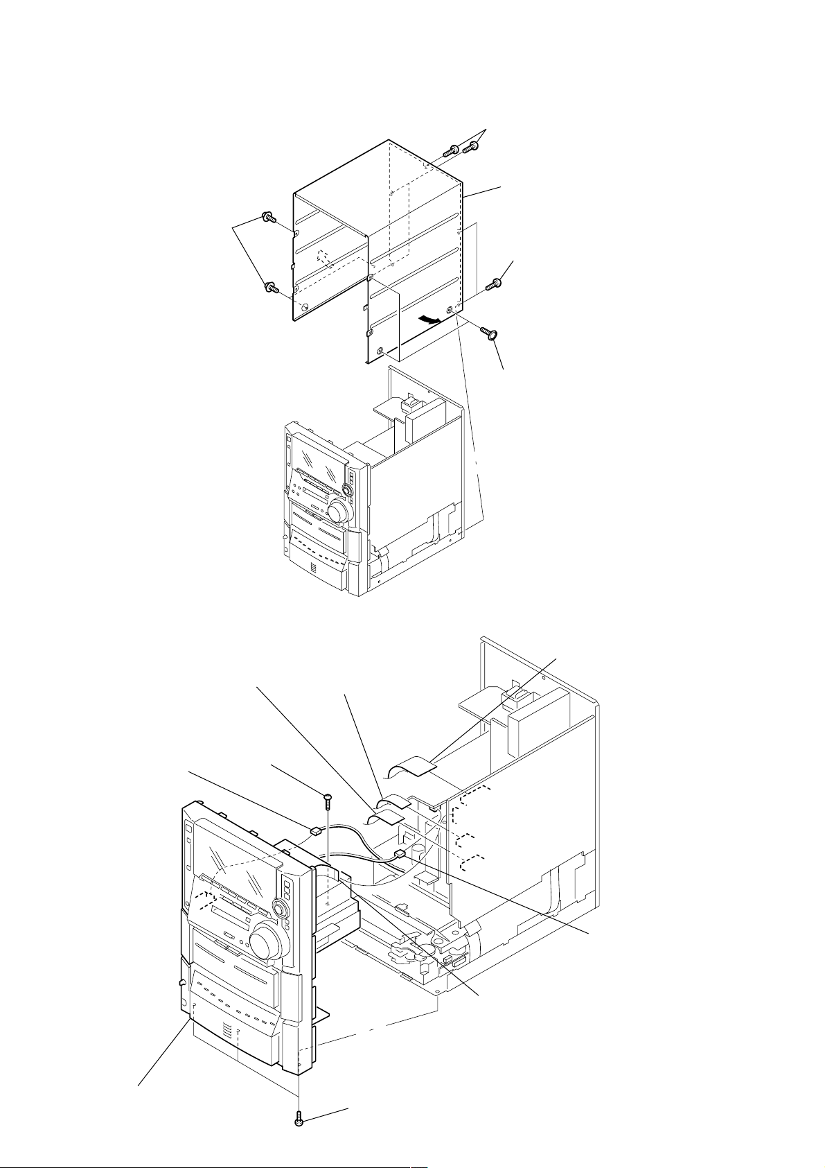
3-2. FRONT PANEL SECTION
4 flat type wire (17core)
(CN304)
8 screw
5 connector
(CN1691)
(BVTP 3 × 8)
3 flat type wire (15core)
(CN305)
2 flat type wire (25core
(CN701)
6 connector
(CN914)
1 flat type wire (11core)
(CN503)
18
9 front panel section
7 three screws
(BVTT 3 × 6)
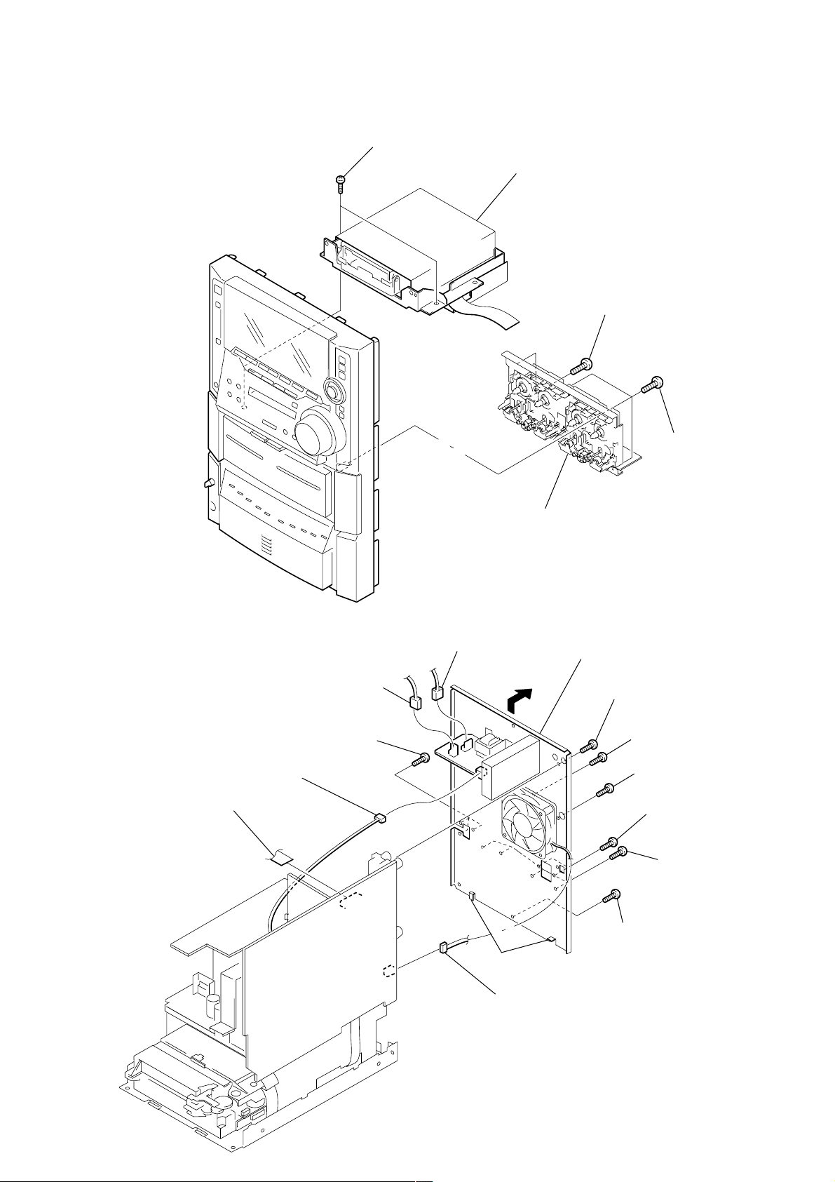
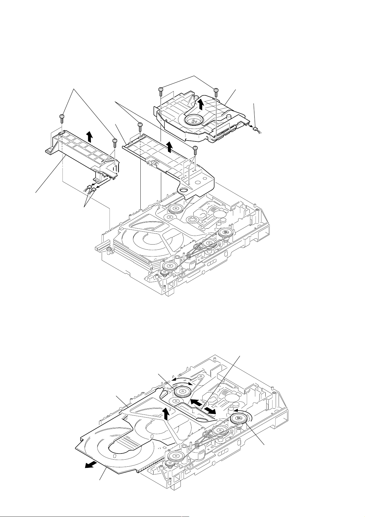
3-3. MD MECHANISM SETION
n
TAPE MECHANISM DECK SECTION
(TCM-230AWR12)
4 two screws
(BVTP 3 × 8)
5 MD mechanism deck section
(MDM-7B)
2 two screws
(BVTP 3 × 8)
1 three screws
(BVTP 3 × 8)
3 tape mechanism deck section
(TCM-230AWR12)
3-4. BACK PANEL SECTION
2 connector
(CN903)
1 flat type wire (13core)
(CN502)
4 connector
(CN902)
qa three screws
(BVTP 3 × 8)
3 connector
(CN901)
claws
qd connector
(CN941)
qs Remove the back panel sectio
in the arrow direction.
0 screw
(BVTP 3 × 8)
9 screw
(BVTP 3 × 8)
8 screw
(BVTP 3 × 8)
7 two screws
(BVTP 3 × 8)
6 four screws
(BVTP 3 × 8)
5 screw
(BVTP 3 × 8)
19
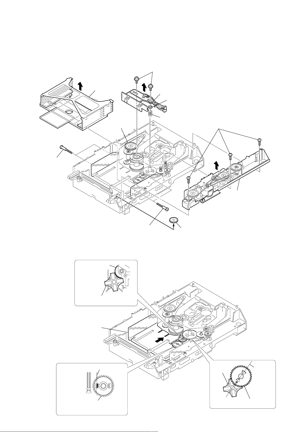
3-5. MD MECHANISM DECK SECTION (MDM-7B)
)
qs two screws
(BVTPWH M3), step
qd MD mechanism deck
(MDM-7B)
8 two claws
1 three screws
(BVTP 3 × 8)
2 plate (B), shield
5 flat type wire (17core)
(CN1004)
6 flat type wire (27core)
(CN1003)
qa two screws
(BVTPWH M3), step
3 screw
(BVTP 3 × 8)
9 DIGITAL board
7 screw
(BVTP 3 × 8)
3-6. MAIN BOARD, FRONT AMP BOARD
qf two screws
(BVTP 3 × 8)
qg Remove the FRONT AMP board
in the arrow direction.
1 screw
(BVTP 3 × 8)
0 flat type wire (25core)
(CN1001)
4 shield (U)
qs two screws
(BVTP 3 × 8)
0 connector
(CN801)
qd heat sink
qa two screws
(BVTP 3 × 16)
7 two connectors
(CN803, CN804)
8 MAIN board
20
2 bracket (MD-R)
9 connector
(CN913)
3 connector
(CN713)
4 flat type wire (17core)
(CN522)
5 flat type wire (13core
(CN523)
6 two screws
(BVTP 3 × 8)
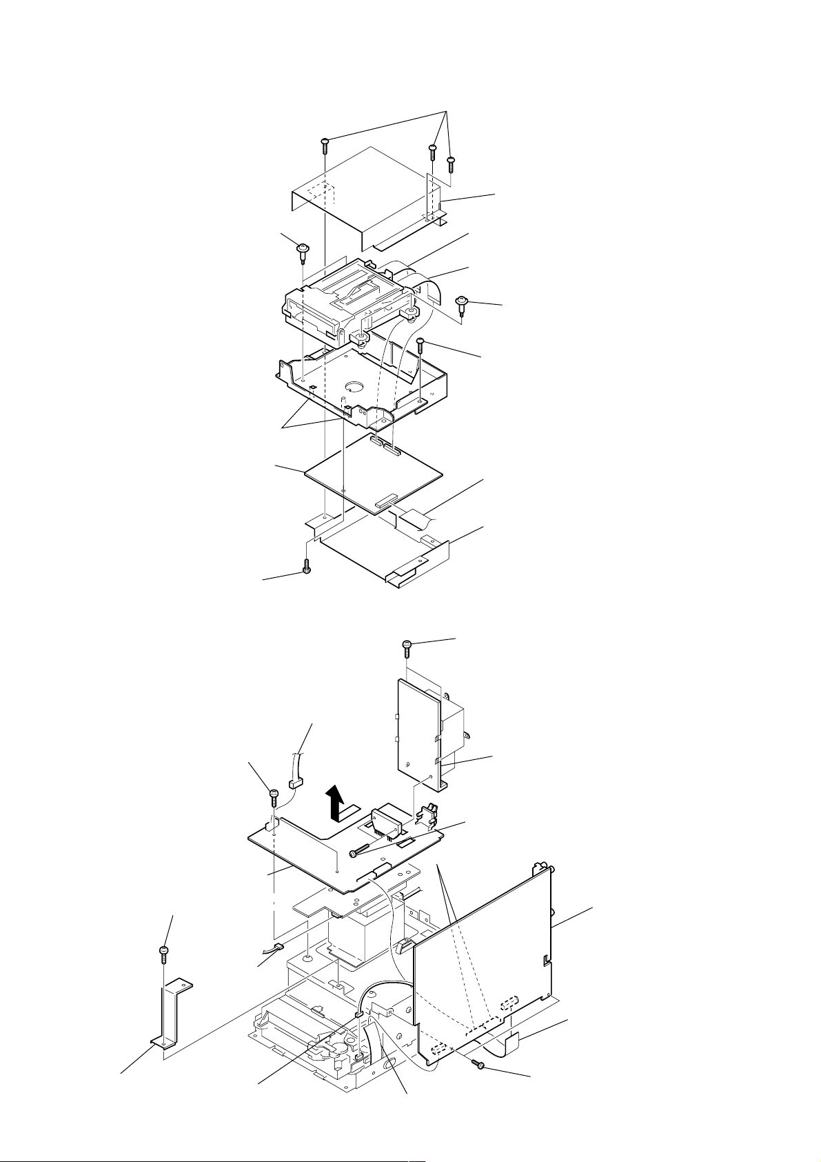
3-7. CD BASE UNIT
1 three screws
(BVTP 3 × 6)
3 two screws
(PTPWH M 2.6)
3 two screws
(PTPWH M 2.6)
4 two springs (insulator),
compression
4 two springs (insulator),
compression
5 CD base unit
(BU-K4BD40)
2 chassis
n
(BU-K4BD40)
3-8. CD MECHANISM DECK SECTION
(CDM53F-K4BD40)
4 four screws
(sumitite (B3), +BV)
2 two screws
(BVTT 3 × 6)
3 chassis, sub
5 CD mechanism deck sectio
(CDM53F-K4BD40)
1 three screws
(BVTT 3 × 6)
21
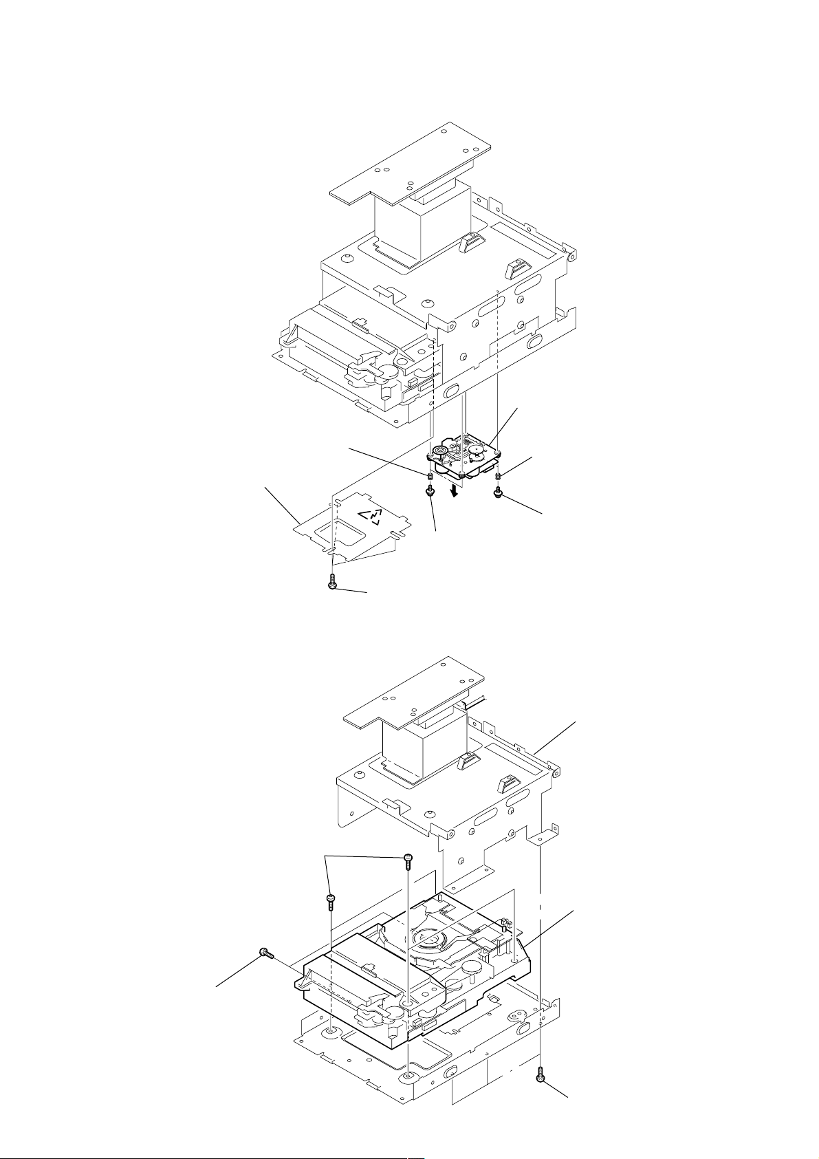
3-9. FITTING BASE (GUIDE) ASSY, BRACKET (CHASSIS) AND
FITTING BASE (MAGNET) ASSY
7 four screws
(BVTP M2.6)
2 four screws
(BVTP M2.6)
4 five screws
(BVTP M2.6)
5 bracket
(chassis)
3 base
(guide) assy, fitting
1 two connectors
(CN709, 715)
8 base (magnet) assy, fitting
6 connector
(CN710)
3-10. TRA Y (SUB)
1 Rotating the pulley (LD), shift the slider (selection) in the arrow A direction.
2 Rotating the pulley (mode) in the arrow direction, adjust the tray (sub) to be removed.
3 Rotating the pulley (LD), shift the slider (selection) in the arrow B direction.
4 Rotating the pulley (mode) in the arrow direction, remove the tray (sub) to be removed.
pulley (LD)
stocker
section
tray (sub)
slider (selection)
A
B
pulley (mode)
22
3-11. CHASSIS (MOLD B) SECTION, STOCKER SECTION AND
)
SLIDER (SELECTION)
Note : In mounting the parts, refer to page 24 and 25.
6 two screws
(PTPWH M2.6)
5 stocker
section
7 slider (selection)
8 washer
4 two step
screws
3-12. GEARS INSTALLATION
3 gear (gear B)
portion A
pulley (LD)
4 two step screws
9 compression
spring
3 gear (eject)
1 three screws
(BVTP M2.6)
2 chassis (mold B) section
Note: Rotating the pulley (LD),
shift the slider (selection
to the left.
Adjust the gear (gear B) with the
portion A as shown.
1 Slide the slider (U/D)
fully in the arrow
direction.
2 gear (U/D slider)
slider (U/D) gear
Adjust the gear so that it meshes with
the bottom tooth of slider (U/D)gear,
as shown.
4 gear (gear A)
gear
(gear B)
Adjust so as to be aligned with
gear (B) linearly,as shown.
linearly
23
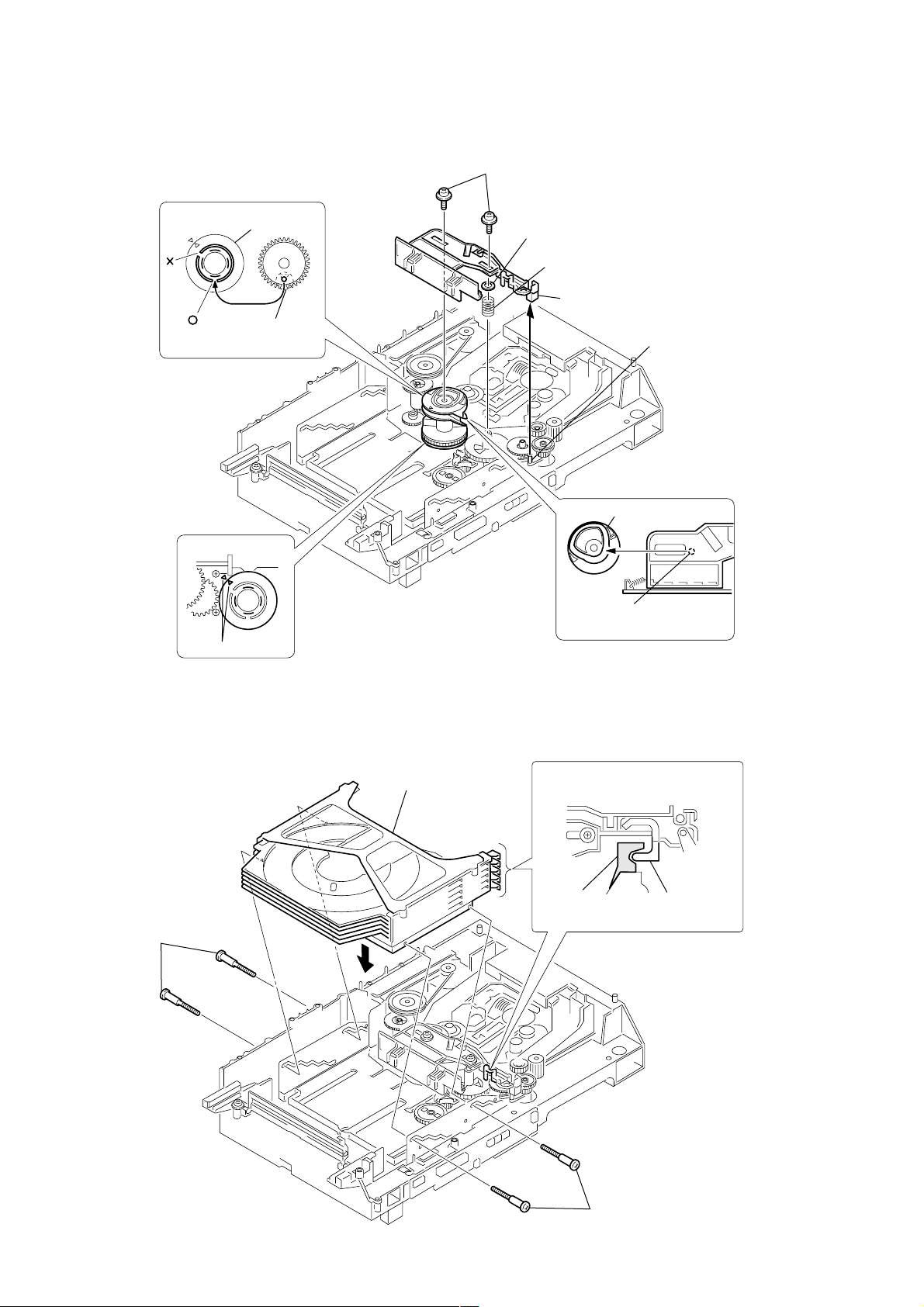
3-13. SLIDER (SELECTION) INSTALLATION
2 gear (chuking)
rotary encoder
Align with the slot of
rotary encoder.
1 rotary encoder
6 two screws
(PTPWH M2.6)
5 washer
4 compression spring
7 Insert the slider (selection)
into the portion A.
portion A
3 convex portion of
slider (selection)
gear (chuking)
align marking
3-14. STOCKER SECTION INSTALLATION
3 two step screws
1 stocker section
Insert a convex portion into
a groove of gear (chuking).
2 portion A of tray (sub)
Hook the portion A of tray (sub)
to the slider (selection).
potion A
of tray (sub)
sticking of
slider (selection)
24
3 two step screws
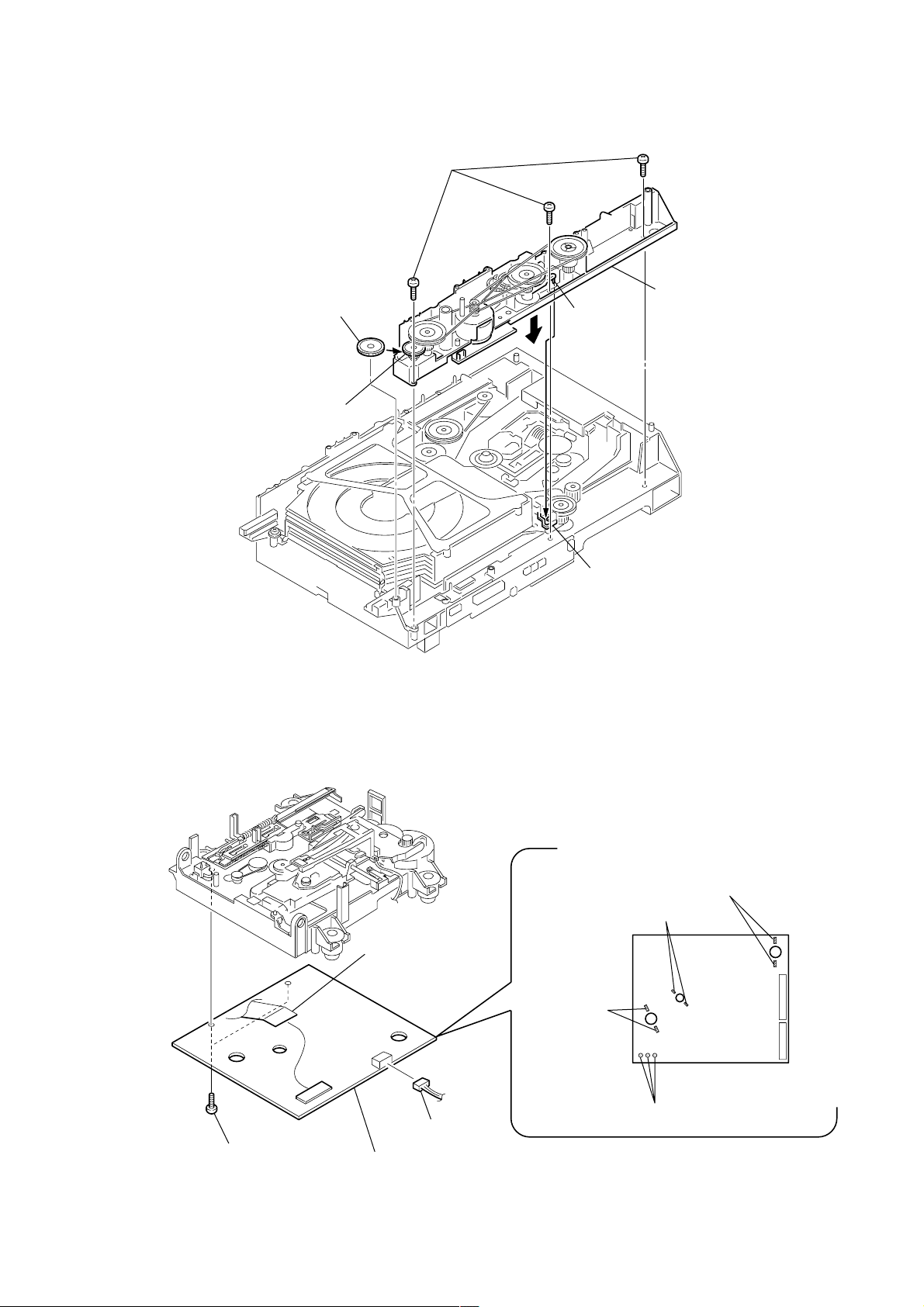
3-15. CHASSIS (MOLD B) SECTION INSTALLATION
n
3 three screws
(BVTP M2.6)
gear (LD deceleration)
3-16. BD (MD) BOARD
2 Insert the gear (eject)
under the gear (LD
deceleration).
portion A
portion B of
slider (selection)
1 Insert the portion A of
chassis (mold B) sectio
into the portion B of
slider (selection).
3 two screws
(BTP 2 × 6)
5 connector
(CN101)
4 BD board
1 connector
(CN104)
2 Remove the solder
(Two portion)
2 Remove the solder
(Two portion)
2 Remove the solder
(Two portion)
M102
M101
M103
S102
2 Remove the solder
(Three portion)
25

SECTION 4
TEST MODE
[MC Cold Reset]
• The cold reset clears all data including preset data stored in the
RAM to initial conditions. Execute this mode when returning
the set to the customer.
Procedure:
1. Press three buttons x , DISPLA Y , and DISC 5 simultaneously.
2. The fluorescent indicator tube displays “COLD RESET” and
the set is reset.
[CD Ship Mode]
• This mode moves the optical pick-up to the position durable to
vibration. Use this mode when returning the set to the customer
after repair.
Procedure:
1. Press ?/1 button to turn the set ON.
2. Press V-GROOVE button and ?/1 button simultaneously.
3. After the “STANDBY” display blinks six times, a message
“LOCK” is displayed on the fluorescent indicator tube, and the
CD ship mode is set.
[MC Hot Reset]
• This mode resets the set with the preset data kept stored in the
memory. The hot reset mode functions same as if the power
cord is plugged in and out.
Procedure:
1. Press three buttons x , DISPLA Y , and DISC 1 simultaneously.
2. The fluorescent indicator tube becomes blank instantaneously,
and the set is reset.
[CD Service Mode]
• This mode can run the CD sled motor freely . Use this mode, for
instance, when cleaning the optical pick-up.
Procedure:
1. Press ?/1 button to turn the set ON.
2. Select the function “CD”.
3. Press three buttons x , DISPLA Y , and Z 3 simultaneously.
4. The CD service mode is selected.
5. With the CD in stop status, turn the shuttle knob clockwise to
move the optical pick-up to outside track, or turn the shuttle
knob counter-clockwise to inside track.
6. To exit from this mode, perform as follows:
1) Move the optical pick-up to the most inside track.
2) Press three buttons in the same manner as step 2.
Note: • Always move the optical pick-up to most inside track when exit-
ing from this mode. Otherwise, a disc will not be unloaded.
• Do not run the sled motor excessively, otherwise the gear can be
chipped.
[VACS ON/OFF Mode]
• This mode is used to switch ON and OFF the VACS (Variable
Attenuation Control System).
Procedure:
Press the PUSH ENTER and x buttons simultaneously. The
message “VACS OFF” or “VACS ON” appears.
[Change-over of MW Tuner Step between 9 kHz and
10 kHz]
• A step of MW channels can be changed over between 9 kHz
and 10 kHz.
Procedure:
1. Press ?/1 button to turn the set ON.
2. Select the function “TUNER”, and press TUNER/BAND
button to select the BAND “MW”.
3. Press ?/1 button to turn the set OFF.
4. Press MODE SELECT and ?/1 buttons simultaneously , and
the display of fluorescent indicator tube changes to “MW 9 k
STEP” or “MW 10 k STEP”, and thus the channel step is
changed over.
[GC Test Mode]
• This mode is used to check the software version, FL tube, LED,
keyboard and VACS.
Procedure:
1. Press three buttons x , DISPLA Y , and DISC 2 simultaneously.
2. LEDs and fluorescent indicator tube are all turned on.
3. When you want to enter the software version display mode,
press DISC 1 . The model number and destination are displayed.
4. Each time DISC 1 is pressed, the display changes starting
from MC version, GC version, VC version, CD version, CDM
version, ST version, TC version, TA version, TM version and
BR version in this order, and returns to the model number and
destination display.
5. When DISC 3 is pressed while the version numbers are being
displayed except model number and destination, year, month
and day of the software creation appear. When DISC 3 is
pressed again, the display returns to the software version display.
When DISC 1 is pressed while year, month and day of the
software creation are being displayed, the year, month and day
of creation of the software versions are displayed in the same
order of version display.
6. Press DISC 2 button, and the key check mode is activated.
7. In the key check mode, the fluorescent indicator tube displays
“K 0 VO 0 STICK N”. Each time a button is pressed, “K 0”
value increases. However, once a button is pressed, it is no longer
taken into account.
“VO 0” value increases like 1, 2, 3 ... if rotating VOLUME
knob in “+” direction, or it decreases like 0, 9, 8 ... if rotating in
“–” direction.
Moving the stick changes the “STICK N” display.
When moved up : “STICK
When moved down : “STICK r”
When moved to the left : “STICK T”
When moved to the right : “STICK t”
8. Also when DISC 3 is pressed after lighting of all LEDs and FL
tubes, value of VACS appears.
9. To exit from this mode, press three buttons in the same manner
as step 1, or disconnect the power cord.
R”
26

[MC Test Mode]
• This mode is used to check operations of the respective sections
of Amplifier, Tuner, CD and T ape.
Procedure:
1. Press the ?/1 button to turn on the set.
2. Press the three buttons of x , DISPLAY and DISC 3
simultaneously.
3. A message “TEST MODE” appears on the FL display tube.
4 When f (STIC UP) button is pressed, GEQ increases to its
maximum and a message “GEQ MAX” appears.
5. When F (STIC DOWN) button is pressed, GEQ decreases to
its minimum and a message “GEQ MIN” appears.
6. When g (STIC LEFT) or G (STIC RIGHT) button is pressed,
GEQ is set to flat and a message “GEQ FLAT” appears.
7. When the VOLUME control knob is turned clockwise even
slightly, the sound volume increases to its maximum and a
message “VOLUME MAX” appears for two seconds, then the
display returns to the original display.
8. When the VOLUME control knob is turned counter-clockwise
even slightly, the sound volume decreases to its minimum and
a message “VOLUME MIN” appears for two seconds, then
the display returns to the original display.
9. In the test mode, the default-preset channel is called even when
the TUNER is selected and an attempt is made to call the preset
channel that has been stored in memory, by operating the Shuttle
knob. (It means that the memory is cleared.)
10. When CD is selected and press MODE SELECT , and press
PUSH ENTER when “Set up Mode” is displayed.
Press PUSH ENTER when “CD Set up?” is displayed.
Move the stick left and right to display “CD Edit Start?”, and
press PUSH ENTER , the disc that is being chucked at this
moment becomes the default setting. It means that the default
disc only is accessed when any other discs are selected even
though the display indication changes accordingly. At the same
time, the Z1 to Z5 cannot be accepted. (It means that the
tray motor and the turntable motor are disabled of their
operation.)
11. When a tape is inserted in Deck B and recording is started, the
input source function selects VIDEO automatically.
12. When x button is pressed to stop recording, the Tape (Deck)
B is selected and tape is rewound using the m button, tape
is rewound, tape is stops at around the record-starting position
and playback of the recorded portion of the tape is started. If
P AUSE is inserted even once during recording, tape is rewound
to the position around the P AUSE position and is played back.
13. When the HI-SPEED CD-MD SYNC Button is press during
playback of Deck B, either normal speed or high speed can be
selected by this button.
14. Select the desired loop by pressing MODE SELECT , and
press PUSH ENTER when “Set up Mode” is displayed.
Press PUSH ENTER when “CD Set up?” is displayed.
Move the stick left and right to display “Tape Set Up?”, and
press PUSH ENTER .
Press PUSH ENTER when “Direction Set Up?” is displayed.
Move the stick left and right to display “Cycle?”, and press
PUSH ENTER .
Insert a test tape AMS-110A or AMS-RO to Deck A.
15. Press the SYNC REC button to enter the AMS test mode.
16. After a tape is rewound first, the FF AMS is checked, and the
mechanism is shut off after detecting the AMS signal twice.
17. Then the REW AMS is checked and the mechanism is shut off
after detecting the AMS signal twice.
18. When the check is complete, a message of either OK or NG
appears.
19. When you want to exit this mode, press the ?/1 button twice.
The cold reset is enforced at the same time.
27

[Aging Mode]
This mode can be used for operation check of CD section and tape deck section.
• If an error occurred:
The aging operation stops and display status.
• If no error occurs:
The aging operation continues repeatedly.
1. Operating method of Aging Mode
Turn on the main power and select “CD” of the function.
1) Set a disc in DISC1 tray. Select ALL DISC CONTINUE, and REPEAT OFF.
2) Load the tapes recording use into the decks A and B respectively.
3) Press three buttons x , DISPLAY , and DISC 4 simultaneously.
4) Aging operations of CD and tape are started at the same time.
• T ape Deck
1. The tape in deck A is rewound. “TAPE A AG-1” is displayed.
2. The FWD side of deck A is played for two minutes.
“TAPE A AG-2” is displayed.
3. The tape in deck A is fast forwarded. “TAPE A AG-3” is displayed. Fast forward is carried out for 20 seconds or to the tape end.
4. The RVS side of deck A is played for two minutes.
“TAPE A AG-4” is displayed.
5. The tape in deck A is rewound. “TAPE A AG-5” is displayed.
6. The FWD side of deck B is played for two minutes.
“T APE B AG-2” is displayed.
7. The tape in deck B is fast forwarded. “TAPE B AG-3” is displayed. Fast forward is carried out for 20 seconds or to the tape end.
8. The RVS side of deck B is played for two minutes.
“T APE B AG-4” is displayed.
9. The tape in deck A is rewound. “TAPE A AG-5” is displayed.
10. Repeated from step 2.
• CD
1. The tray rotates.
2. DISC 5 is chucked.
3. The TOC is read.
4. The first track is played for 3 seconds.
5. The last track is played for 3 seconds.
6. DISC 1 is open.
7. DISC 1 is close.
8. Repeated from step 2.
28

2. Correction of Errors
[When due to tape deck]
Stopped while tape aging operation with the ”” displayed state.
[When due to CD]
Press x , DISPLAY , and CD Z together to display the error code.
• Display of number of mechanism errors
Move the stick to the left and right to display “CDM Err Count *”.
* is the number of mechanism errors.
• Display of mechanism error
Move the stick to the left and right to display “CDM E**D##$$%%!!”.
Move the stick up and down to send the error number.
** : Error number 00 is the latest error.
The larger the number, the older will the error be. (Maximum 9)
## : FF is the mechanism error after mechanism initialization ends.
$$ : Judge from the first digit of the error number. (Don’t care the second digit.)
When the error number is 1 or 2, it indicates mechanism error in tray loading between the stocker position and behind it.
%% : Judge from the first digit of the error number. (Don’t care the second digit.)
When the error number is 2, it indicates mechanism error in the up/down movements of the stocker.
!! : Judge from the first digit of the error number. (Don’t care the second digit.)
When the error number is 2, it indicates mechanism error during switching of the clamper and mode.
• No DISC error display
Move the stick left and right to display “No Disc Count *”.
* means the number of no discs.
• No DISC error display
Move the stick left and right to display “No E**D##$$%%00”.
Move the stick up and down to send the error number.
** : Error number 01 is the latest error.
The larger the number, the older will the error be. (Maximum 3)
## : 01 .... FOCUS ERROR
02 .... GFS ERROR
03 .... SET UP ERROR
$$ : 00 .... Judged as No DISC without attempting chucking retry
02 .... Judged as No DISC after chucking retry
%% : Judged with the first digit of the error number in the state where No DISC has been determined.
(Don’t care the second digit.)
1 ...... STOP
2 ...... SET UP
3 ...... TOC Read
4 ...... Access
5 ...... PLAY
6 ...... PAUSE
7 ...... Manual Search (during PLAY)
8 ...... Manual Search (during P AUSE)
3. Ending the Aging Mode
1) End the Aging Mode with the power off.
2) To reset the CD error history, be sure to perform cold reset.
29

4-1. PRECAUTIONS FOR USE OF TEST MODE
• As loading related operations will be performed regardless of the test mode operations being performed, be sure to check that the disc
is stopped before setting and removing it.
Even if the MD Z button is pressed while the disc is rotating during continuous playback, continuous recording, etc., the disc will not
stop rotating.
Therefore, it will be ejected while rotating.
Be sure to press the CLEAR button while REC IT is lit, and press the MD Z button while REC IT is off after the disc stops rotating.
4-1-1. Recording laser emission mode and operating buttons
• Continuous recording mode (CREC 1MODE) (C35)
• Laser power check mode (LDPWR CHECK) (C13)
• Laser power adjustment mode (LDPWR ADJUS) (C04)
• Iop check (Iop Compare) (C27)
• Iop value nonvolatile writing (Iop NV Save) (C06)
• Traverse (MO) check (EF MO CHECK) (C14)
• Traverse (MO) adjustment (EF MO ADJUS) (C07)
• When pressing the MD REC button.
4-2. SETTING THE TEST MODE
The following are two methods of entering the test mode.
Procedure 1:In the power ON state, set the function to MD, and while pressing the DISPLA Y and x buttons together, press V-GROOVE .
When the test mode is set, “[Check]” will be displayed. Move the multi-stick to switch between the following three groups;
··· y Check y Service y Develop y ···.
Procedure 2:In the power ON state, set the function to MD, and while pressing the DISPLA Y and x buttons together, press the NAME
EDIT/CHARACTER button.
When the test mode is set, “AUTO CHECK” will be displayed. By setting the test mode using this method, only the “Check”
group of method 1 can be executed.
NOTE: Do not use the test mode in the [Develop] group.
If used, the unit may not operate normally.
If the [Develop] group is set accidentally, press the CLEAR button while REC IT is lit, immediately to exit the [Develop] group.
4-3. EXITING THE TEST MODE
Press the MD Z button while REC IT is off. The disc is ejected when loaded, and “Standby” display blinks, and the STANDBY state is set.
4-4. BASIC OPERATIONS OF THE TEST MODE
Operate using the multi-stick, PUSH ENTER button, MD REC MODE button, CLEAR button, NAME EDIT/CHARACTER button.
Function name
CLEAR button (When REC IT is lit)
PUSH ENTER button
Mulit stick (Left or Right)
MD REC MODE button (When REC IT is lit)
NAME EDIT/CHARACTER button
Cancel or move to top hierarchy
Set
Select
Set submenu
Switching of button operations (REC IT lights up/goes off)
Function
30
 Loading...