

Sony HCD-ZX10D Service Manual

HCD-ZX10D
Q
Q
3
7
6
3
1
5
1
5
0
SERVICE MANUAL
Ver 1.0 2004.07
TEL 13942296513 QQ 376315150 892498299
HCD-ZX10D is the amplifier, disc player, tape
deck and tuner section in LBT-ZX10D.
This system incorporates Dolby* Digital, Dolby Pro
Logic (II) adaptive matrix surround decoder, and the
DTS** Digital Surround System.
*Manufacturedunderlicense from Dolby
Laboratories.
“Dolby”, “Pro Logic”, and the double-D symb ol are
trademarks of Dolby Laboratories.
** Manufactured under license from Digital Theater
Systems, Inc.
“DTS” and “DTS Digital Surround” are registered
trademarks of Digital Theater Systems. Inc.
TEL
13942296513
DVD
Section
Tape deck Model Name Using Similar Mechanism HCD-GN100D
Section Tape Transport Mechanism Type CWM43RR35
Q
Q
SPECIFICATIONS
Model Name Using Similar Mechanism NEW
DVD Mechanism Type CDM79B-DVBU64
Optical Traverse Unit Name DBU-3
7
3
8
6
3
9
1
5
2
1
5
4
9
8
2
E Model
Australian Model
8
9
4
2
9
8
0
9
2
9
9
TEL 13942296513 QQ 376315150 892498299
9
Amplifier section
The following measured at AC 120, 220, 240 V,
50/60 Hz
DIN power output (rated)
Front speakers: 140 + 140 watts
(6 ohms at 1 kHz, DIN)
Center speaker: 55 watts
(24 ohms at 1 kHz, DIN)
Surround speakers: 140 + 140 watts
(6 ohms at 1 kHz, DIN)
Continuous RMS power ouput (reference)
Front speakers: 180 + 180 watts
(6 ohms at 1 kHz, 10%
THD)
Center speaker: 70 watts
(24 ohms at 1 kHz, 10%
THD)
Surround speakers: 180 + 180 watts
(6 ohms at 1 kHz, 10%
THD)
Inputs
PHONO IN (phono jacks):
sensitivity 3 mV,
impedance 47 kOhms
MIC (phone jack): sensitivity 1 mV,
impedance 10 kOhms
GAME INPUT AUDIO L/R (phono jacks):
sensitivity 250 mV,
impedance 47 kOhms
GAME INPUT VIDEO (phono jack):
VIDEO/SAT IN L/R (phono jacks):
Outputs
PHONES (stereo phone jack):
VIDEO/SAT OUT L/R (phono jacks):
VIDEO OUT (phono jack):
COMPONENT VIDEO OUT:
S VIDEO OUT (4-pin/mini-DIN jack):
1 Vp-p, 75 ohms
sensitivity 250 mV/
450 mV, impedance
47 kOhms
accepts headphones of
8ohms or more
voltage 250 mV,
impedance 1 kOhm
max. output level 1 Vp-p,
load impedance 75 ohms
Y: 1 Vp-p, 75 ohms
B/CB: 0.7 Vp-p, 75 ohms
P
R/CR: 0.7 Vp-p, 75 ohms
P
Y: 1 Vp-p, unbalanced,
Sync negative
C: 0.286 Vp-p load
impedance 75 ohms
SUBWOOFER OUT (phono jack):
voltage 250 mV,
impedance 1 kOhm
SPEAKERS:
FRONT L/R, SURROUND L/R:
Use only the supplied
speaker SS-ZX10D
CENTER: Use only the supplied
speaker SS-CT381
Disc player section
System Compact disc and digital
audio and video system
Laser Semiconductor laser
(DVD: λ=650 nm,
CD: λ=780 nm)
Emission duration:
continuous
Frequency response DVD (PCM 48 kHz):
2 Hz – 22 kHz (±1 dB)
CD: 2 Hz – 20 kHz
(±0.5 dB)
Video color system format
NTSC, PAL
– Continued on next page –
DVD DECK RECEIVER
w
w
9-879-053-01
2004G0579-1
© 2004.07
w
.
xia
Sony Corporation
Home Audio Company
Published by Sony Engineering Corporation
o
y
u
1
6
3
.
c
o
m
HCD-ZX10D
This appliance is
classified as a CLASS 1
LASER product. This
label is located on the
rear exterior.
Tape deck section
Recording system 4-track 2-channel, stereo
Q
Q
Frequency response 50 – 13,000 Hz (±3 dB),
Tuner section
FM stereo, FM/AM superheterodyne tuner
FM tuner section
Tuning range 87.5 – 108.0 MHz
Antenna FM lead antenna
Antenna terminals 75 ohms unbalanced
Intermediate frequency 10.7 MHz
AM tuner section
Tuning range 531 – 1, 602 kHz
TEL 13942296513 QQ 376315150 892498299
Antenna AM loop antenna
Antenna terminals External antenna terminal
Intermediate frequency 450 kHz
General
Power requirements
Australian model: 230 – 240 V AC,
Other models: 120 V, 220 V or
7
3
using Sony TYPE I tapes
(50 kHz step)
(with the tuning interval
set at 9 kHz)
530 – 1, 710 kHz
(with the tuning interval
set at 10 kHz)
50/60 Hz
230 – 240 V AC, 50/60 Hz
Adjustable with voltage
selector
6
3
1
5
1
5
Notes on chip component replacement
• Never reuse a disconnected chip component.
0
• Notice that the minus side of a tantalum capacitor may be
damaged by heat.
Flexible Circuit Board Repairing
• Keep the temperature of the soldering iron around 270 ˚C
during repairing.
• Do not touch the soldering iron on the same conductor of the
circuit board (within 3 times).
• Be careful not to apply force on the conductor when soldering
or unsoldering.
CAUTION
Use of controls or adjustments or performance of procedures
other than those specified herein may result in hazardous radiation
exposure.
The following caution label is located inside the
apparatus.
8
9
2
4
9
8
2
9
9
TEL 13942296513 QQ 376315150 892498299
Power consumption 370 watts
Dimensions (w/h/d) (Unit)
TEL
Mass (Unit) Approx. 20.0 kg
Design and specifications are subject to change
without notice.
Approx. 362 × 437 ×
465 mm
13942296513
Q
Q
3
7
6
3
1
5
1
5
0
8
9
2
4
9
8
2
9
9
2
w
w
w
.
xia
SAFETY-RELATED COMPONENT WARNING!!
COMPONENTS IDENTIFIED BY MARK 0 OR DOTTED LINE
WITH MARK 0 ON THE SCHEMATIC DIAGRAMS AND IN
o
y
THE PARTS LIST ARE CRITICAL TO SAFE OPERATION.
u
1
6
REPLACE THESE COMPONENTS WITH SONY PARTS WHOSE
PART NUMBERS APPEAR AS SHOWN IN THIS MANUAL OR
IN SUPPLEMENTS PUBLISHED BY SONY.
3
.
c
o
m
Region code of DVDs you can
playback on this system
Your system has a region code printed on the
back of the unit and will only playback DVDs
labeled with identical region code.
DVDs labeled will also be played back on
this system.
If you try to playback any other DVD, the
message “Playback prohibited by area
limitations.” will appear on the TV screen.
Depending on the DVD, no region code
indication may be labeled even though playing
the DVD is prohibited by area restrictions.
Discs that this system cannot
playback
•CD-ROMs other than those with extension
“.MP3”, “.JPG” or “.JPEG”.
•CD-Rs/CD-RWs other than those recorded in
the following formats:
–Audio CD format.
–VIDEO CD format.
–MP3 (MPEG 1 Audio Layer 3)/JPEG
format that conforms to ISO 9660
1)
Level
1/Level 2 or Joliet.
•Data part of CD-Extras
2)
.
•Data part of Mixed CDs
3)
.
•Super Audio CDs.
•DVD-RWs in VR (Video Recording) mode.
•DVD-ROMs.
•DVD-RAMs.
• DVD Audio discs.
• DVDs with a different region code.
•Progressive JPEG format files.
•Disc with non-standard shapes (e.g., heart,
square, star).
•Discs with adhesive, cellophane tape or
sticker still left on them.
1)
ISO 9660 Format
The most common international standard for the
logical format of files and folders on a CD-ROM.
There are several specificat ion levels. In Level 1, file
names must be in the 8.3 format (no more than eight
characters in the name, no more than three characters
in the extension and in capital letters). Folder names
can be no longer than eight characters. There can be
no more than eight nested folder levels. Level 2
specifications allow file names and folder names up
to 31 characters long. Each folder can have up to
eight nested folder levels.
2)
CD-Extra
This format records audio (audio CD data) on the
tracks in session 1 and data on the tracks in session 2.
3)
Mixed CD
This format records data on the first track and audio
(audio CD data) on the second and s ubsequent tracks
of a session.
Notes about CD-R/CD-RW/
DVD-R/DVD-RW (Video mode)/
DVD+R/DVD+RW
•In some cases, CD-Rs, CD-RWs, DVD-Rs,
DVD-RWs (Video mode) (DVD-RWs
created in video mode have the same format
as DVD VIDEO), DVD+Rs or DVD+RWs
cannot be played back on this system
depending upon the recording quality or
physical condition of the disc, or the
characteristics of the recording device.
Furthermore, the disc will not playback if it
has not been correctly finalized. For more
information, see the operation instructions for
the recording device.
•A disc recorded in packet write format cannot
be played back.
ALL
x
Region code
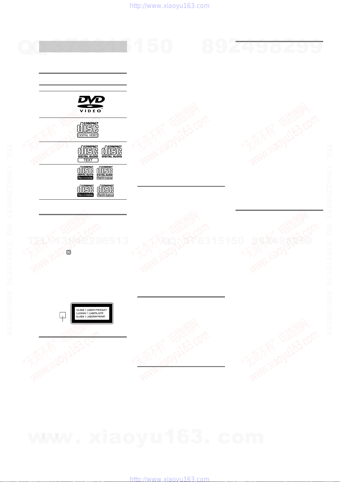
You can playback the following discs on this
system. Other discs cannot be played back.
List of playable discs
The “DVD VIDEO” logo is a trademark.
Playable discs
Format of discs Disc logo
DVD VIDEOs
VIDEO CDs
Audio CDs
CD-R/CD-RW
(Audio CDs/Discs
with MP3 audio
tracks/Discs with
JPEG image files)
Note on playback operations
of DVDs and VIDEO CDs
Some playback operations of DVDs and VIDEO
CDs may be intentionally set by software
producers. Since this system playback DVDs
and VIDEO CDs according to the disc contents
the software producers designed, some playback
features may not be available. Also, refer to the
instructions supplied with the DVDs or VIDEO
CDs.
Music discs encoded with
copyright protection
technologies
This product is designed to playback discs that
conform to the Compact Disc (CD) standard.
Recently, various music discs encoded with
copyright protection technologies are marketed
by some record companies. Please be aware that
among those discs, there are some that do not
conform to the CD standard and may not be
playable by this product.
Cautions when playing a disc
that is recorded in Multi
Session
•This system can playback Multi Session discs
when an MP3 audio track is contained in the
first session. Any subsequent MP3 audio
tracks recorded in later sessions can also be
played back.
•This system can playback Multi Session discs
when a JPEG image file is contained in the
first session. Any subsequent JPEG image
files recorded in later sessions can also be
played back.
• If audio tracks and images in audio CD format
or VIDEO CD format are recorded in the first
session, only the first session will be played
back.
•When you playback Multi Session discs with
different formats in each session, the format
of the first session is recognized as the disc
type. Tracks in the second and subsequent
sessions are played back if they are the same
formats as the first session except for audio
CD and VIDEO CD format.
•CD-Rs and CD-RWs recorded in Multi
Session that have not ended by “closing the
session” are not supported.
Copyrights
This product incorporates copyright protection
technology that is protected by U.S. patents and
other intellectual property rights. Use of this
copyright protection technology must be
authorized by Macrovision, and is intended for
home and other limited viewing uses only unless
otherwise authorized by Macrovision. Reverse
engineering or disassembly is prohibited.
HCD-ZX10D
7
Q
Q
TEL 13942296513 QQ 376315150 892498299
TEL
3
13942296513
6
1
5
1
3
5
0
Q
Q
4
2
9
8
1
3
6
7
3
5
1
5
0
8
9
9
8
2
4
2
9
8
9
2
9
9
TEL 13942296513 QQ 376315150 892498299
9
w
w
w
.
xia
o
y
u
1
6
3
.
c
o
m
3

HCD-ZX10D
TABLE OF CONTENTS
7
Q
Q
1. SERVICING NOTES ............................................ 5
2. GENERAL .............................................................. 7
3. DISASSEMBLY
3-1. FLOW CHART .................................................................. 9
3-2. COVER (TOP) ................................................................. 10
3-3. CASE ................................................................................ 10
3-4. LOADING PANEL .......................................................... 11
3-5. FRONT PANEL SECTION ............................................ 11
3-6. BACK PANEL SECTION .............................................. 12
3-7. MAIN BOARD ............................................................... 12
3-8. BRACKET (TR) BLOCK ................................................ 13
3-9. DVD MECHANISM DECK ............................................ 13
TEL 13942296513 QQ 376315150 892498299
3-10. OPTICAL TRAVERSE UNIT ......................................... 14
3-11. RF BOARD ...................................................................... 14
3-12. TAPE MECHANISM DECK ........................................... 15
4. TEST MODE ............................................................... 16
5. MECHANICAL ADJUSTMENTS ........................ 27
6. ELECTRICAL ADJUSTMENTS ..........................27
7. DIAGRAMS
7-1. BLOCK DIAGRAM – RF SERVO SECTION – ........... 29
7-2. BLOCK DIAGRAM
– VIDEO/CHANGER SECTION – ................................. 30
7-3. BLOCK DIAGRAM
– TUNER/TAPE SECTION – .......................................... 31
TEL
7-4. BLOCK DIAGRAM – AUDIO SECTION – ................. 32
7-5. BLOCK DIAGRAM – AMP SECTION – ..................... 33
7-6. BLOCK DIAGRAM
– PANEL/POWER SUPPLY SECTION – ....................... 34
7-7. PRINTED WIRING BOARD – RF BOARD –............. 36
7-8. SCHEMATIC DIAGRAM – RF BOARD –................... 37
7-9. PRINTED WIRING BOARD
– DMB07 BOARD (Component Side) –.......................... 38
7-10. PRINTED WIRING BOARD
– DMB07 BOARD (Conductor Side) – .......................... 39
7-11. SCHEMATIC DIAGRAM
– DMB07 BOARD (1/8) – ............................................... 40
7-12. SCHEMATIC DIAGRAM
– DMB07 BOARD (2/8) – ............................................... 41
7-13. SCHEMATIC DIAGRAM
– DMB07 BOARD (3/8) – ............................................... 42
7-14. SCHEMATIC DIAGRAM
– DMB07 BOARD (4/8) – ............................................... 43
7-15. SCHEMATIC DIAGRAM
– DMB07 BOARD (5/8) – ............................................... 44
7-16. SCHEMATIC DIAGRAM
– DMB07 BOARD (6/8) – ............................................... 45
7-17. SCHEMATIC DIAGRAM
– DMB07 BOARD (7/8) – ............................................... 46
7-18. SCHEMATIC DIAGRAM
– DMB07 BOARD (8/8) – ............................................... 47
7-19. PRINTED WIRING BOARD
– VIDEO BOARD – ......................................................... 48
7-20. SCHEMATIC DIAGRAM
– VIDEO BOARD – ......................................................... 49
7-21. PRINTED WIRING BOARDS
– CHANGER SECTION – ............................................... 50
w
3
13942296513
w
w
6
.
1
3
xia
5
o
1
y
5
u
0
7-23. PRINTED WIRING BOARD
– MAIN BOARD – .......................................................... 51
7-24. SCHEMATIC DIAGRAM
– MAIN BOARD (1/5) –.................................................. 52
7-25. SCHEMATIC DIAGRAM
– MAIN BOARD (2/5) –.................................................. 53
7-26. SCHEMATIC DIAGRAM
– MAIN BOARD (3/5) –.................................................. 54
7-27. SCHEMATIC DIAGRAM
– MAIN BOARD (4/5) –.................................................. 55
7-28. SCHEMATIC DIAGRAM
– MAIN BOARD (5/5) –.................................................. 56
7-29. PRINTED WIRING BOARDS
– FRONT AMP SECTION –............................................ 57
7-30. SCHEMATIC DIAGRAM
– FRONT AMP SECTION (1/2) – ................................... 58
7-31. SCHEMATIC DIAGRAM
– FRONT AMP SECTION (2/2) – ................................... 59
7-32. PRINTED WIRING BOARD
– SURROUND BOARD – ............................................... 60
7-33. SCHEMATIC DIAGRAM
– SURROUND BOARD – ............................................... 61
7-34. PRINTED WIRING BOARDS
– PANEL SECTION (1/5) – ............................................. 62
7-35. SCHEMATIC DIAGRAM
– PANEL SECTION (1/5) – ............................................. 63
7-36. PRINTED WIRING BOARD
– PANEL SECTION (2/5) – ............................................. 64
7-37. SCHEMATIC DIAGRAM
– PANEL SECTION (2/5) – ............................................. 65
7-38. PRINTED WIRING BOARDS
Q
Q
7-39. SCHEMATIC DIAGRAM
7-40. PRINTED WIRING BOARDS
7-41. SCHEMATIC DIAGRAM
7-42. PRINTED WIRING BOARDS
7-43. SCHEMATIC DIAGRAM
7-44. PRINTED WIRING BOARDS
7-45. SCHEMATIC DIAGRAM
8. EXPLODED VIEWS
8-1. CASE SECTION ............................................................. 93
8-2. PANEL BOARD SECTION............................................ 94
8-3. FRONT PANEL SECTION .............................................. 95
8-4. BACK PANEL SECTION ................................................ 96
8-5. HEAT SINK SECTION.................................................... 97
8-6. CHASSIS SECTION ........................................................ 98
8-7. DVD MECHANISM DECK SECTION-1
8-8. DVD MECHANISM DECK SECTION-2
8-9. OPTICAL BLOCK SECTION ....................................... 101
9. ELECTRICAL PARTS LIST............................... 102
1
7
3
– PANEL SECTION (3/5) – ............................................. 66
– PANEL SECTION (3/5) – ............................................. 67
– PANEL SECTION (4/5) – ............................................. 68
– PANEL SECTION (4/5) – ............................................. 69
– PANEL SECTION (5/5) – ............................................. 70
– PANEL SECTION (5/5) – ............................................. 71
– POWER SUPPLY SECTION – ..................................... 72
– POWER SUPPLY SECTION – ..................................... 73
(CDM79B-DVBU64) ....................................................... 99
(CDM79B-DVBU64) ..................................................... 100
6
3
8
6
3
.
9
1
1
5
c
2
5
o
4
0
m
9
8
9
8
2
4
2
9
8
9
2
9
9
TEL 13942296513 QQ 376315150 892498299
9
4
SECTION 1
SERVICING NOTES
HCD-ZX10D
NOTES ON HANDLING THE OPTICAL PICK-UP
Q
TEL 13942296513 QQ 376315150 892498299
BLOCK OR BASE UNIT
Q
The laser diode in the optical pick-up block may suffer electrostatic
break-down because of the potential difference generated by the
charged electrostatic load, etc. on clothing and the human body.
During repair, pay attention to electrostatic break-down and also
use the procedure in the printed matter which is included in the
repair parts.
The flexible board is easily damaged and should be handled with
care.
NOTES ON LASER DIODE EMISSION CHECK
The laser beam on this model is concentrated so as to be focused on
the disc reflective surface by the objective lens in the optical pickup block. Therefore, when checking the laser diode emission,
observe from more than 30 cm away from the objective lens.
UNLEADED SOLDER
Boards requiring use of unleaded solder are printed with the leadfree mark (LF) indicating the solder contains no lead.
(Caution: Some printed circuit boards may not come printed with
Unleaded solder has the following characteristics.
• Unleaded solder melts at a temperature about 40 °C higher
TEL
• Strong viscosity
• Usable with ordinary solder
7
3
the lead free mark due to their particular size)
: LEAD FREE MARK
than ordinary solder.
Ordinary soldering irons can be used but the iron tip has to be
applied to the solder joint for a slightly longer time.
Soldering irons using a temperature regulator should be set to
about 350 °C.
13942296513
Caution: The printed pattern (copper foil) may peel away if
Unleaded solder is more viscou-s (sticky, less prone to flow)
than ordinary solder so use caution not to let solder bridges
occur such as on IC pins, etc.
It is best to use only unleaded solder but unleaded solder may
also be added to ordinary solder.
6
the heated tip is applied for too long, so be careful!
3
1
5
1
5
0
Q
Q
NOTE OF REPLACING THE DMB07 BOARD
When replacing the DMB07 board, since the adjustment value is
not set up correctly, “Drive Auto Adjustment” can’t be performed.
In this case, initialize memory in the following procedures.
Procedure:
1. Set the test mode. (See page 18)
2. Press the [2] key on the remote commander, and set the
3. Press the [6] key on the remote commander, and set the “2-6,
4. Press the [CLEAR] key on the remote commander, and initialize
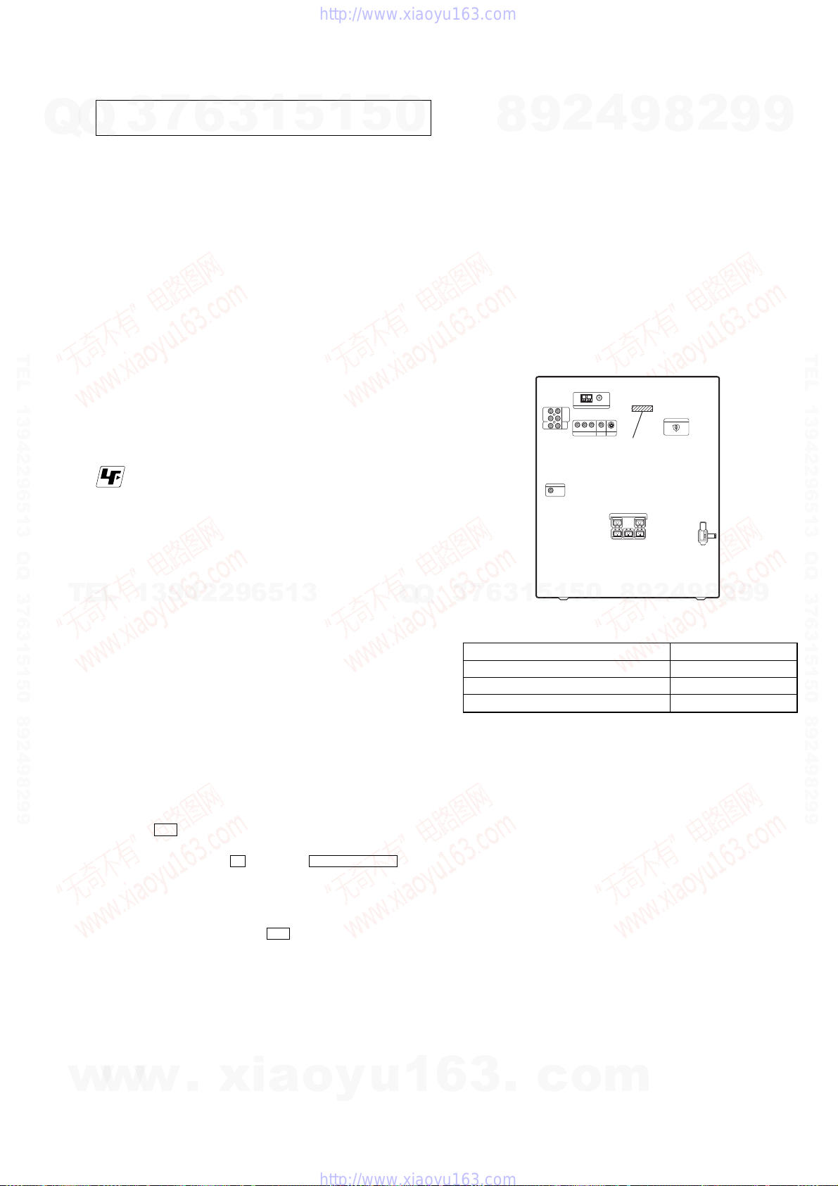
• MODEL IDENTIFICATION
–Back Panel–
7
3
Singapore and Malaysia models 4-252-689-6[]
Iranian model 4-252-689-7[]
Australian model 4-252-689-8[]
4
2
9
8
“DRIVE MANUAL OPERATION”. (See page 21)
Memory Check”. (See page 23)
Memory.
0
5
1
5
1
3
6
Model Name Part No.
9
PART No.
2
9
8
8
4
2
9
8
2
9
9
9
TEL 13942296513 QQ 376315150 892498299
9
RELEASING THE DISC TRAY LOCK
The disc tray lock function for the antitheft of an demonstration
disc in the store is equipped.
Releasing Procedure :
1. Press
2. Press the [FUNCTION] button to select the “DVD”.
3. Press two buttons of x (DVD) and Z
Note: When “LOCKED” is displayed, the tray lock is not released by
w
w
?/1 button to turn the power on.
OPEN/CLOSE
simultaneously and hold down until “UNLOCKED” displayed
on the fluorescent indicator tube (around 5 seconds).
turning power on/off with the ?/1 button.
w
.
xia
o
y
u
1
6
3
.
c
o
m
5
p
HCD-ZX10D
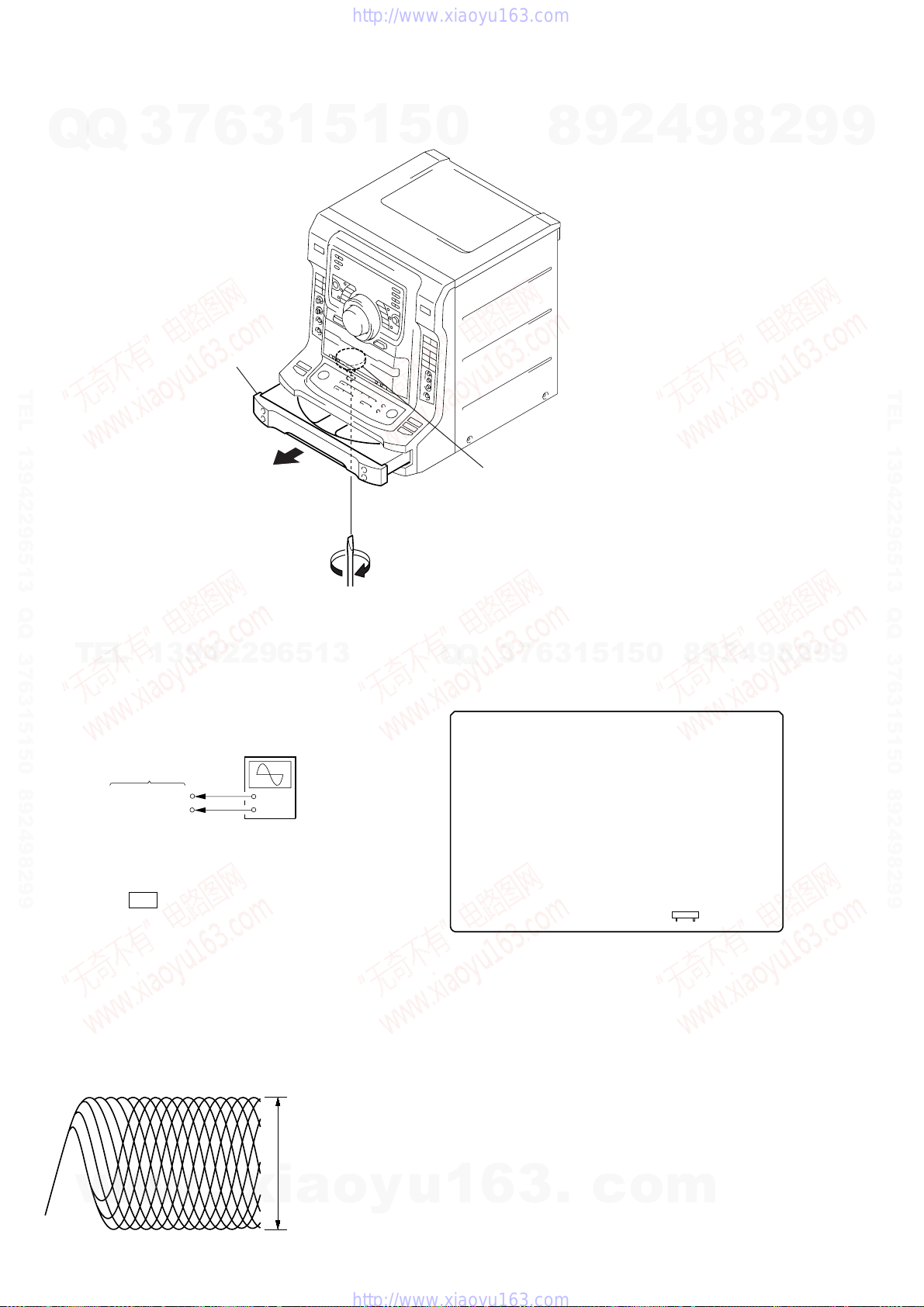
HOW TO OPEN THE DISC TRAY WHEN POWER SWITCH TURNS OFF
Q
Q
7
3
2
Pull-out the disc tray.
6
3
1
5
1
5
0
8
9
2
4
9
8
2
9
9
TEL 13942296513 QQ 376315150 892498299
1
Tu rn the gear (chuck)
in the direction of
arrow
A
TEL
DECISION TO PASS OR FAIL OF THE OPTICAL PICK-UP
BLOCK
Connection:
13942296513
oscilloscope
DMB07 board
CN901
1
CN901
3
pin
pin
+
–
7
3
Q
Q
Checking Location:
– DMB07 BOARD (Component Side) –
A
6
.
3
1
5
1
5
0
8
9
2
4
9
8
2
9
TEL 13942296513 QQ 376315150 892498299
9
Procedure:
1. Connect an oscilloscope to test point 1 pin and 3 pin of
CN901 on the DMB07 board.
2. Press the ?/1 button to turn the power on.
3. Put the disc (LUV-P01) (Part No. 4-999-032-01) (CD) in to
playback.
4. Confirm that oscilloscope waveform is clear and check RF
signal level is correrect or not.
5. Put the disc (TDV-520CSO) (Part No. J-2501-236-A) (DVD)
in to playback.
6. Perform Comfirmation in the same manner as step 4.
Note: A clear RF signal waveform means that the shape “◊” can be clearly
distinguished at the center of the waveform.
RF signal waveform
VOLT/DIV: 200 mV
TIME/DIV: 500 ns
±
0.2 Vp-p
±
0.2 Vp-
o
y
6
w
w
w
.
xia
CD: 1.05
DVD: 1.09
u
1
6
3
.
c
o
CN901
17
m
t
t
t
1
23 456 7 89 q;qaq
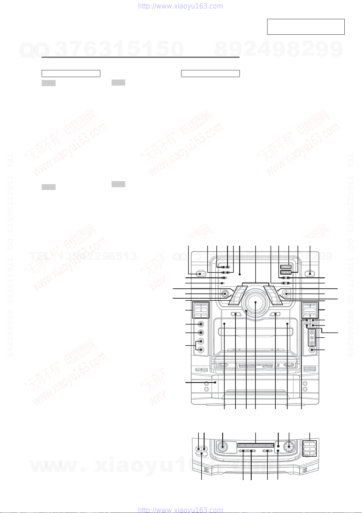
SECTION 2
GENERAL
• LOCATION OF CONTROLS
7
Q
Q
TEL 13942296513 QQ 376315150 892498299
TEL
3
Main unit
ALPHABETICAL ORDER
A – D
ALBUM +/– rl
AMP MENU qk
CD SYNC w;
CLOCK/TIMER SELECT 2
CLOCK/TIMER SET 5
Deck A ea
Deck B wh
DIRECTION eh
DISC 1 ~ 5 rh
DISC SKIP td
Disc tray es
DISPLAY 3
Display 6
DOLBY PL II tf
DVD MENU qj
DVD TOP MENU qg
E – H
ECHO LEVEL eg
EFFECT ON/OFF ej
ENTER qh
EX-CHANGE ts
FLASH rg
FM MODE 8
FUNCTION qs
GAME ws
GAME INPUT AUDIO L/R
(jacks) wd
GAME INPUT VIDEO (jack) wd
GAME MIXING wa
13942296513
6
1
3
I – Q
ILLUMINATION rs
IR (receptor) ra
JOG rk
MEMORY 9
MIC 1/MIC 2 (jacks) ed
MIC LEVEL ef
MODE t;
P FILE ek
PHONES (jack) wf
PLAY MODE rd
Power illuminator wl
Preset Effect buttons 7
SALSA/REGGAE/POP/
SAMBA/TANGO/ROCK/
JAZZ/DANCE/MOVIE/
GAME
R – Z
REC PAUSE/START wg
REPEAT rf
SLEEP 4
SPEAKERS t;
SOUND FIELD r;
TUNER/BAND q;
TUNER ENTER qd
TUNING –/+ qa
TUNING MODE qf
VOLUME +/– wk
X-GROOVE el
X-ROUND ON/OFF rj
5
1
5
0
SYMBOLS
?/1 (power) 1
A Z e;
Z B wj
V/v/B/b
DVD Function:
Z OPEN/CLOSE ta
NX (play/pause) rl
x (stop) rl
m/M (rewind/fast forward)
rl
./> (go backward/go
forward) rl
TAPE A function:
h/H (play) eh
x (stop) eh
.m/M> eh
TAPE B function:
h/H (play) ql
x (stop) ql
.m/M> ql
3
Q
Q
rs
ra
r;
el
ek
ej
eh
eg
ef
ed
qh
7
8
6
3
1
R
9
5
2
1
5
HCD-ZX10D
This section is extracted from
instruction manual.
4
0
9
8
9
2
8
4
2
9
8
s
2
9
9
9
qd
qf
qh
qk
ql
w;
wa
wd
wf
9
TEL 13942296513 QQ 376315150 892498299
qg
qj
ws
w
w
w
es
wgwhwjwke; wlea
rd
.
xia
o
y
u
1
6
3
f
.
c
o
m
d
stat;
rlrkrjrhrgrf
PLAY
MODE
HS s
7

HCD-ZX10D
Remote control
Q
Q
ALPHABETICAL ORDER
A – E
ALBUM + 7
ALBUM – qa
ANGLE qk
AUDIO qk
BAND wg
CLEAR wl
CLOCK/TIMER SELECT e;
CLOCK/TIMER SET e;
DISC SKIP wf
DISPLAY wa
DVD DISPLAY wh
DVD MENU 7
DVD SETUP ws
DVD TOP MENU qa
TEL 13942296513 QQ 376315150 892498299
ENTER wj
TEL
7
3
ea
e;
wl
13942296513
wk
wj
wh
wg
wf
6
F – Z
FM MODE 5
FUNCTION +/– q;
KARAOKE/MPX qf
KEY CONTROL
Numeric buttons qd
PLAY MODE 4
REPEAT 5
SLEEP qh
SLOW / w;
SOUND FIELD +/– wd
SUBTITLE qk
TUNER MEMORY 3
TUNING MODE 4
TUNING +/– wk
TV CH +/– qg
TV/VIDEO ea
TV VOL +/– 2
TV ?/1 qj
VOLUME +/– 8
+–+
–
O
+–
y
y
mM.>
XbB
x
+––
V
bB
+
v
+
–+–
3
1
qj
qk
ql
w;
wa
ws
wd
#/2
qh
qf
qd
qs
qa
0
5
9
1
5
SYMBOLS
?/1 (power) 1
nN (play) 6
X (pause) 6
x (stop) 6
>10 qs
O RETURN ql
m (rewind) w;
M (fast forward) w;
V/v/B/b
. (go backward) wk
> (go forward) wk
+–+
+–
y
mM.>
XbB x
+–
V
bB
v
+
–+–
+
–
–
O
y
0
1
2qg
3
4
5
Q
Q
6
7
8
9
wj
3
7
8
6
Setting the clock
9
1
Press ?/1 to turn on the system.
2
Press CLOCK/TIMER SET.
“CLOCK” appears in the display. Then, the
hour indication flashes in the display.
3
Press V or v repeatedly to set the
hour.
4
Press ENTER.
The minute indication flashes in the
display.
5
Press V or v repeatedly to set the
minute.
6
Press ENTER.
The clock starts functioning.
To adjust the clock
1
Press CLOCK/TIMER SET.
“SET” appears in the display, then “PLAY
SET?” flashes in the display.
2
Press V orv repeatedly to select “CLOCK
SET?”, then press ENTER.
The hour indication flashes in the display.
3
Do the same procedures as step 3 to 6
above.
Notes
•The clock settings are canceled when you disconnect
the power cord or if a power failure occurs.
•You cannot set the clock in Power Saving Mode.
5
1
3
2
1
5
4
0
9
8
9
8
2
4
2
9
8
9
2
9
9
TEL 13942296513 QQ 376315150 892498299
9
8
w
w
w
.
xia
o
y
u
1
6
3
.
c
o
m
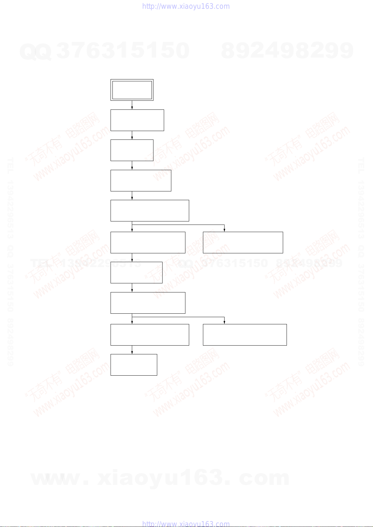
SECTION 3
DISASSEMBLY
• This set can be disassembled in the order shown below.
7
Q
Q
TEL 13942296513 QQ 376315150 892498299
3
3-1. FLOW CHART
6
1
3
5
SET
3-2. COVER (TOP)
(Page 10)
3-3. CASE
(Page 10)
3-4. LOADING PANEL
(Page 11)
1
5
0
8
9
2
4
9
HCD-ZX10D
2
8
9
9
TEL 13942296513 QQ 376315150 892498299
TEL
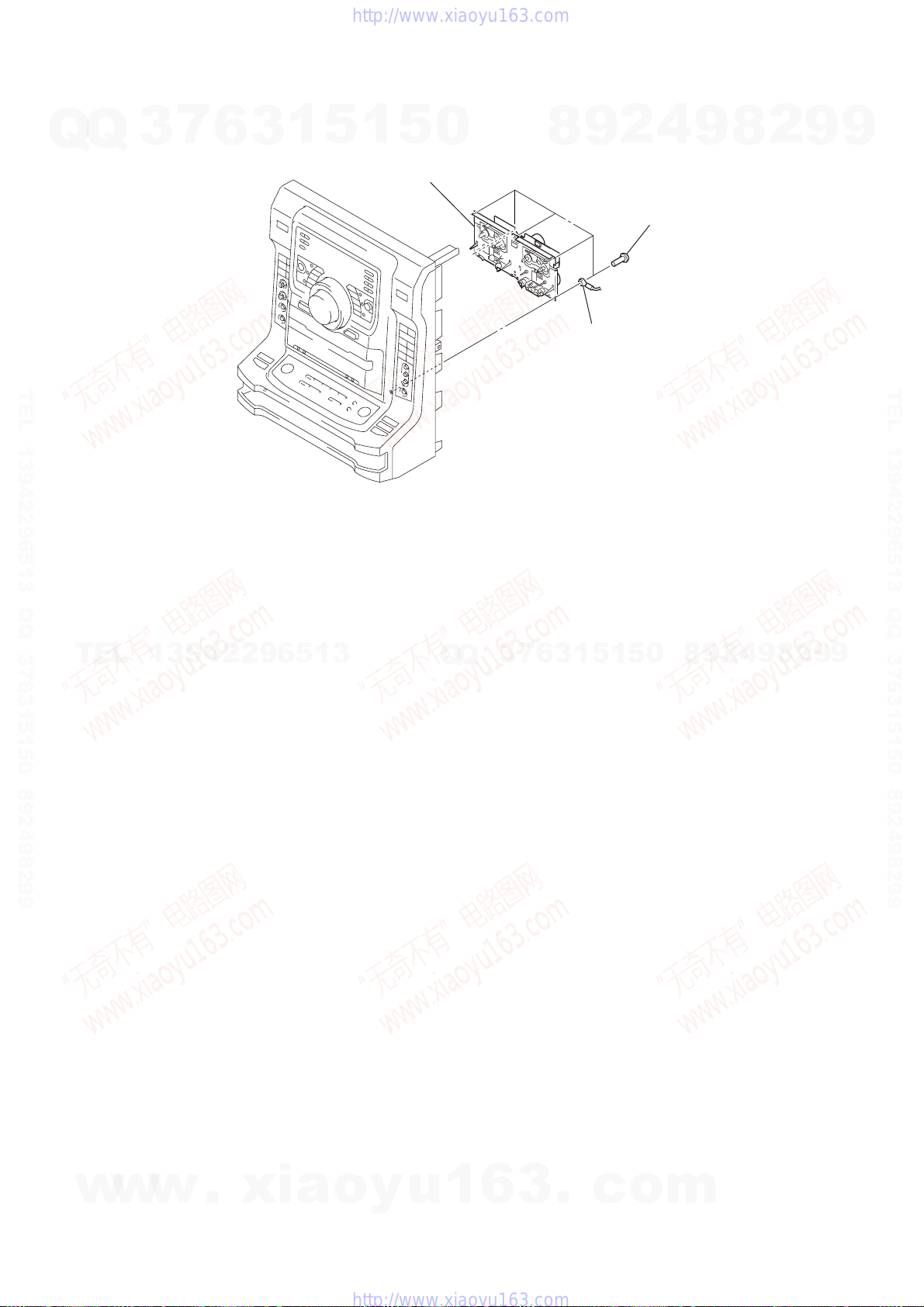
3-5. FRONT PANEL SECTION
(Page 11)
3-6. BACK PANEL SECTION
(Page 12)
13942296513
3-7. MAIN BOARD
(Page 12)
3-8. BRACKET (TR) BLOCK
(Page 13)
3-9. DVD MECHANISM DECK
(Page 13)
3-11. RF BOARD
(Page 14)
Q
Q
3-12. TAPE MECHANISM DECK
(Page 15)
0
5
1
5
1
3
6
7
3
3-10. OPTICAL TRAVERSE UNIT
(Page 14)
8
9
2
4
9
8
2
9
9
w
w
w
.
xia
o
y
u
1
6
3
.
c
o
m
9
s
)
HCD-ZX10D
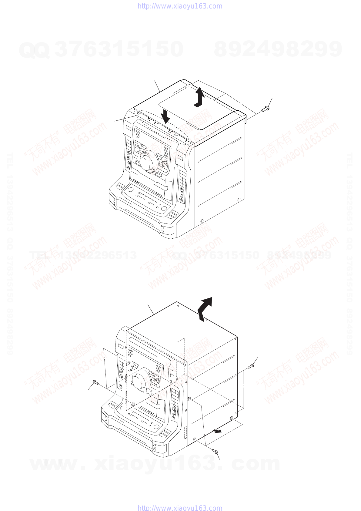
Note: Follow the disassembly procedure in the numerical order given.
7
Q
Q
3-2. COVER (TOP)
3
2
Push the cover (top)
in the direction of arrow
and release six claws.
6
3
1
A
5
1
3
cover (top)
,
5
A
0
8
9
2
4
1
three screw
(BVTP3 × 8)
9
8
2
9
9
TEL 13942296513 QQ 376315150 892498299
TEL
3-3. CASE
13942296513
4
case
Q
Q
3
7
6
3
1
5
1
5
0
8
9
2
4
9
8
2
9
TEL 13942296513 QQ 376315150 892498299
9
10
w
w
2
three screws
(case 3 TP2)
w
.
xia
o
y
u
1
6
3
1
three screws
.
(case 3 TP2)
c
3
o
four screws
(BVTP3
×
m
8
)
Q
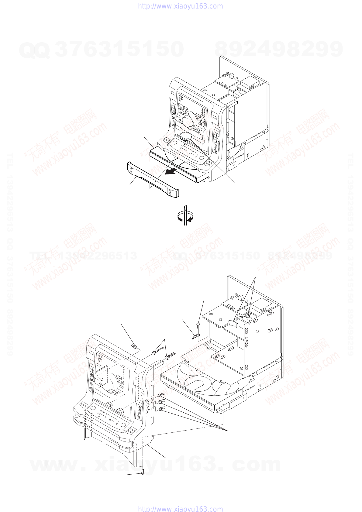
3-4. LOADING PANEL
7
Q
3
6
2
1
5
1
3
Pull-out the tray in the direction
of arrow
B
.
5
0
8
9
2
4
9
HCD-ZX10D
2
8
9
9
TEL 13942296513 QQ 376315150 892498299
B
3
loading panel
A
3-5. FRONT PANEL SECTION
TEL
13942296513
2
connector
(CN920)
4
lead wire
Q
Q
3
7
3
screw
(BVTP3
×
6
8)
3
1
Rotate the gear (chuck)
in the direction of arrow
9
8
0
5
1
5
1
1
two wires (flat type)
(CN104: 13 core, CN507: 21 core
2
4
A
.
9
8
2
9
TEL 13942296513 QQ 376315150 892498299
9
w
w
w
.
xia
5
eight screws
×
(BVTP3
8)
2
two connectors
6
front panel section
o
y
u
1
6
3
.
2
three connectors
(CN801, 802, 803)
c
o
m
11
s
d
HCD-ZX10D
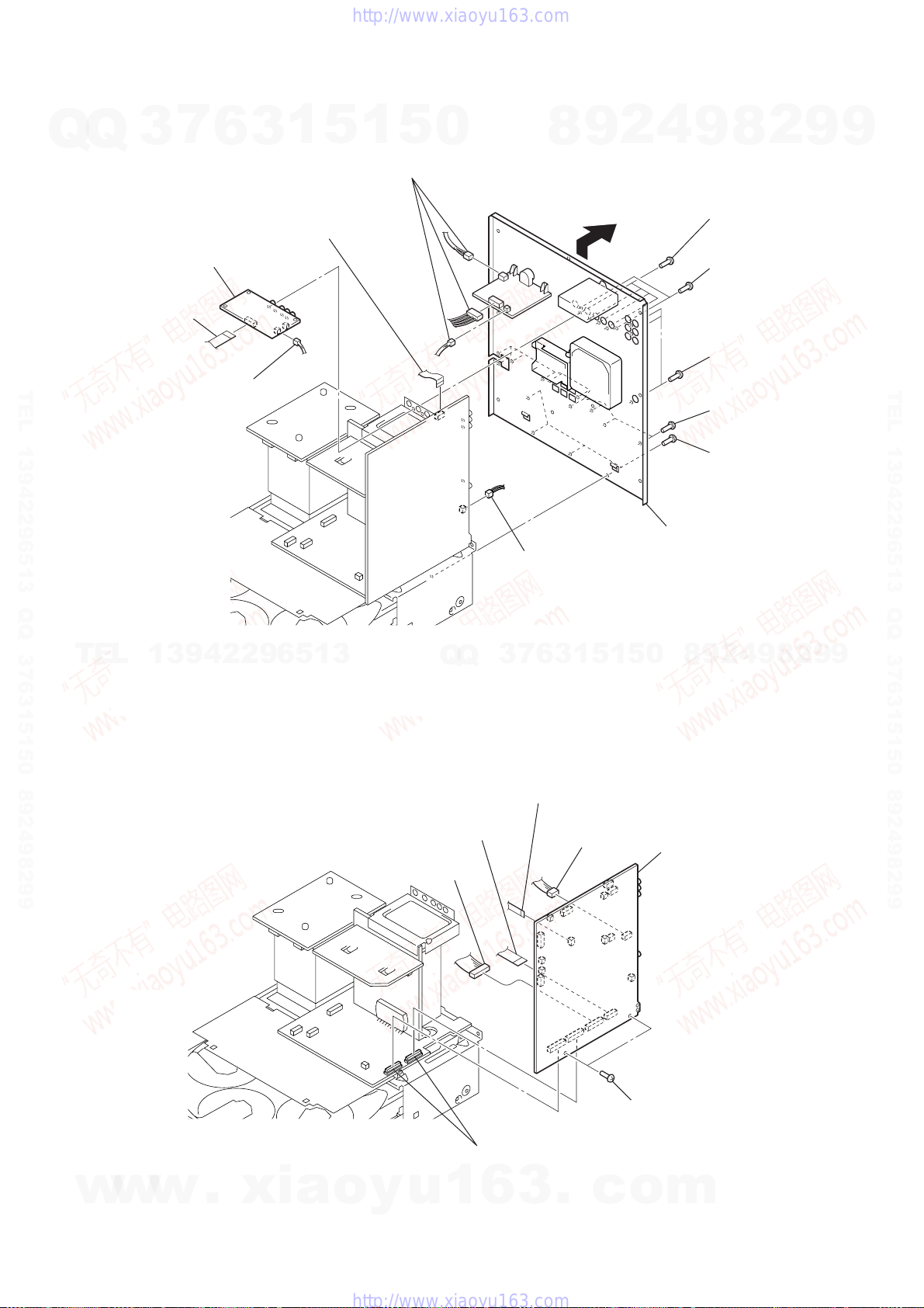
3-6. BACK PANEL SECTION
7
Q
Q
1
wire (flat type)
(17 core) (CN1202)
TEL 13942296513 QQ 376315150 892498299
3
4
VIDEO board
2
connector
(CN1200)
6
1
3
1
wire (flat type)
(11 core) (CN504)
5
1
2
5
three connectors
(CN1000, 1002, 1004)
0
8
9
9
2
4
9
3
5
6
7
8
2
8
four screws
×
(BVTP3
two screws
(BVTP3
three screw
(BVTP3 × 8)
ten screws
(BVTP3
four screws
(BVTP3
8)
×
8)
×
8)
×
8)
9
9
TEL 13942296513 QQ 376315150 892498299
TEL
3-7. MAIN BOARD
13942296513
Q
Q
5
wire (flat type)
(21 core) (CN503)
6
connector
(CN506)
0
connector
(CN513)
3
6
7
3
1
wire (flat type)
(7 core) (CN404)
1
2
connector
(CN502)
5
1
5
qa
back panel section
8
0
7
MAIN boar
9
2
9
9
2
8
9
4
12
w
w
w
.
xia
4
two connectors
(CN601, 602)
o
y
u
1
6
3
.
c
3
two screws
(BVTP3 × 8)
o
m
k
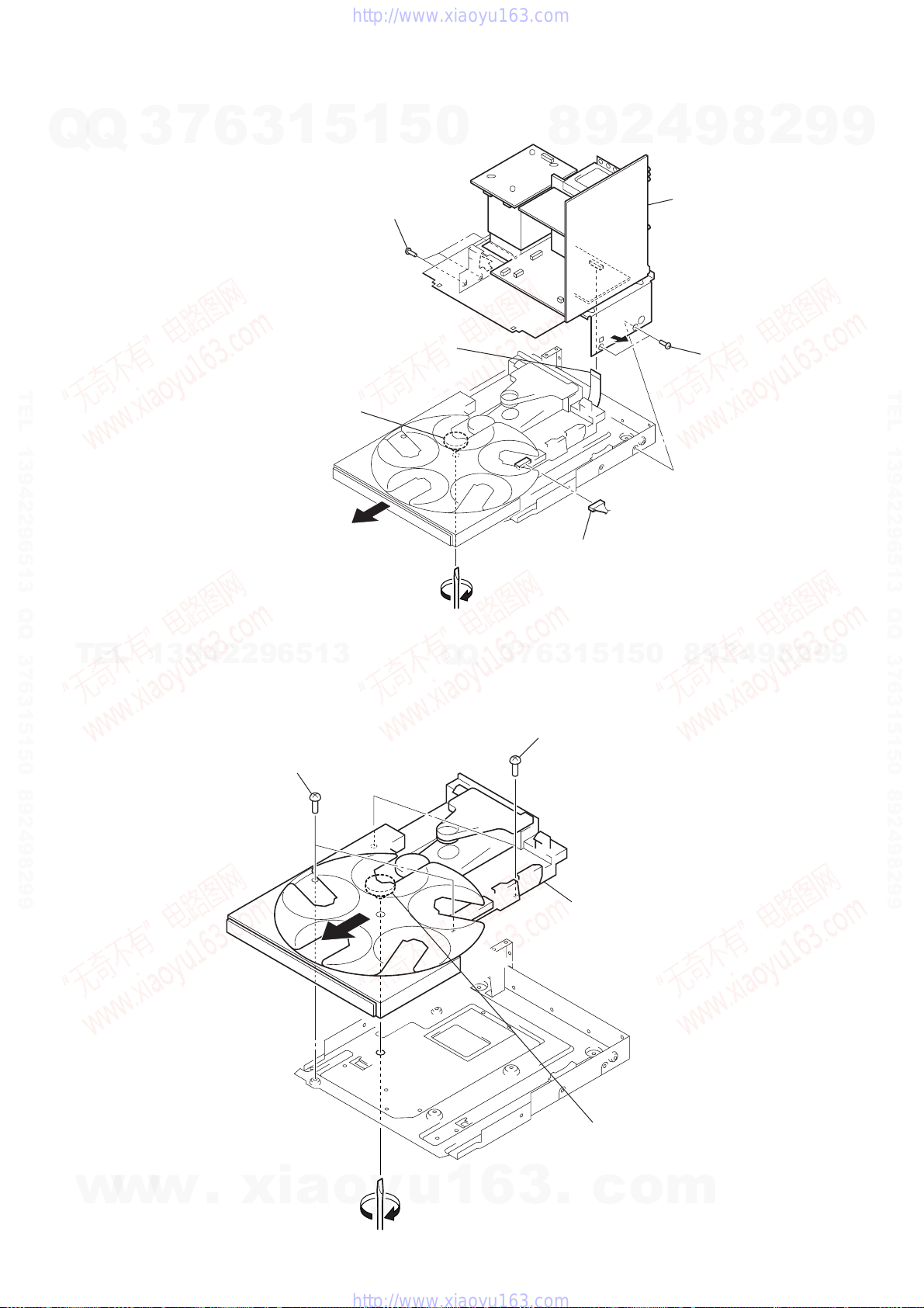
3-8. BRACKET (TR) BLOCK
7
Q
Q
TEL 13942296513 QQ 376315150 892498299
3
6
2
Rotate the gear (chuck)
in the direction of arrow
3
1
5
1
5
three screws
(BVTP3
1
wire (flat type)
(29 core) (CN501)
A
.
5
×
8)
0
8
9
2
4
9
7
bracket (TR) bloc
8
6
two screws
(BVTP3
HCD-ZX10D
2
×
8)
9
9
TEL 13942296513 QQ 376315150 892498299
TEL
13942296513
3-9. DVD MECHANISM DECK
3
two screws
(BV3)
2
3
Q
Q
A
3
7
3
6
4
two screws
(BV3)
4
connector
0
5
1
5
1
5
DVD mechanism deck
8
9
2
4
9
8
2
9
9
w
w
w
.
xia
o
y
u
1
6
3
A
.
1
Rotate the gear (chuck)
in the direction of arrow
c
o
m
A
.
13
HCD-ZX10D
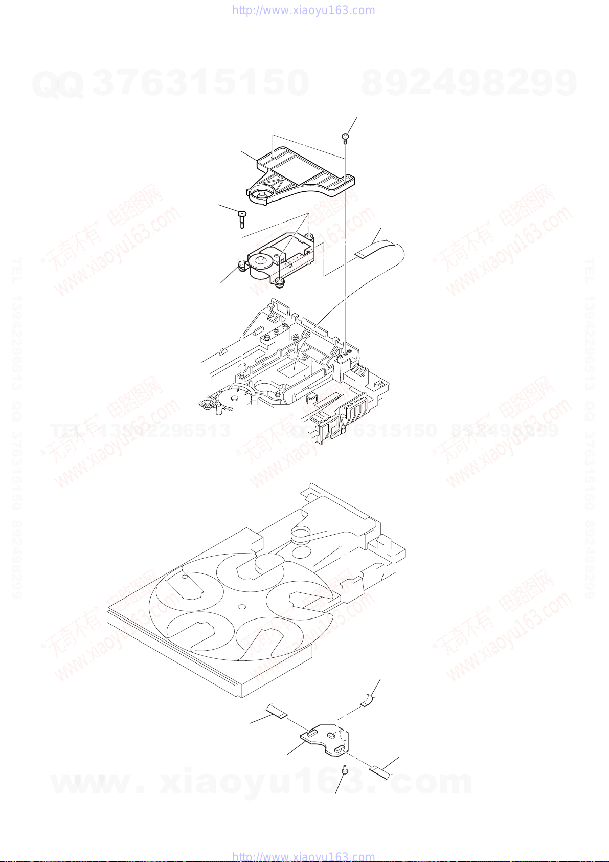
3-10. OPTICAL TRAVERSE UNIT
7
Q
Q
3
6
3
3
three step screws (M)
1
2
chuck assy
5
1
5
0
1
two screws
(BVTP3 × 8)
9
8
4
flexible flat cable
(24 core)
2
4
9
8
2
9
9
TEL 13942296513 QQ 376315150 892498299
5
optical traverse unit
TEL
3-11. RF BOARD
13942296513
Q
Q
3
7
6
3
1
5
1
5
0
8
9
2
4
9
8
2
9
TEL 13942296513 QQ 376315150 892498299
9
14
w
w
w
.
xia
4
wire (flat type)
(29 core) (CN002)
5
RF board
o
y
u
1
6
1
3
two screws
(BTP2.6
×
10)
3
flexible flat cable
(24 core) (CN001)
.
c
2
flexible board
(CN003)
o
m
)
Q
3-12. TAPE MECHANISM DECK
7
Q
3
6
3
1
5
1
5
0
3
tape mechanism deck
8
9
2
lead wire
2
4
1
five screws
(BVTP2.6
9
HCD-ZX10D
2
8
×
8
9
9
TEL 13942296513 QQ 376315150 892498299
TEL
13942296513
Q
Q
3
7
6
3
1
5
1
5
0
8
9
2
4
9
8
2
9
TEL 13942296513 QQ 376315150 892498299
9
w
w
w
.
xia
o
y
u
1
6
3
.
c
o
m
15

HCD-ZX10D
SECTION 4
TEST MODE
GC TEST MODE
This mode is used to check the fluorescent indicator tube, LED,
Q
Q
model, destination, software version, volume, key, jog and VACS
level.
Procedure:
1. Press three buttons of x (TAPE B), [TUNER ENTER] , and
[DISC 2] simultaneously.
2. All LEDs and segments in fluorescent indicator tube are lighted
up.
3. When you want to enter the software version display mode,
press the [DISC 1] button. The model and destination are displayed.
4. Each time [DISC 1] button is pressed, the display changes from
MC version, GC version, CD version, ST version, TC version,
TA version, TM version in this order, and returns to the MC
TEL 13942296513 QQ 376315150 892498299
version display.
5. When [DISC 3] button is pressed while the version numbers are
being displayed except model and destination, the date of the
software creation appear. When [DISC 3] button is pressed again,
the display returns to the software version display. When
[DISC 1] button is pressed while the date of the software creation
is being displayed, the date of the software creation is displayed
in the same order of software version display.
6. Press the [DISC 2] button, the key check mode is activated.
7. In the key check mode, the fluorescent indicator tube displays
“K 0 J0 V0”. Each time a button is pressed, “K” value
increases. However, once a button has been pressed, it is no
longer taken into account.
8. When [DISC 3] button is pressed after all LEDs and segments
in fluorescent indicator tube light up, the fluorescent indicator
tube displays “VACS A APBB”. A is VACS level which is
trigger by signal level while BB is VACS level which is trigger
by APVACS (Abuse Protection VACS).
TEL
9. When [EX-CHANGE] button is pressed after all LEDs and
segments in fluorescent indicator tube light up, alternate
segments in fluorescent indicator tube would light up. If you
press [EX-CHANGE] button again, another half of alternate
segments in fluorescent indicator tube would light up. Pressing
[EX-CHANGE] button again would cause all segments lights up.
10. To release from this mode, press three buttons in the same
manner as step 1, or disconnect the power cord.
MC TEST MODE
This mode is used to check operations of the respective sections of
amplifier, tuner, and tape.
Procedure:
• To enter MC test mode
1. Press three buttons of x (TAPE B), [TUNER ENTER] , and
[DISC 3] simultaneously.
2. The 4 speaker symbols and CD ring indicators flash on the
fluorescent indicator tube. The function is changed to
“VIDEO”.
• Check of amplifier
1. When [ENTER] button is pushed with the up side, GEQ
increases to its maximum and a message “GEQ MAX” appears
on the fluorescent indicator tube.
2. When [ENTER] button is pushed with the down side, GEQ
decreases to its minimum and a message “GEQ MIN” appears
on the fluorescent indicator tube.
3. When [ENTER] button is pushed with the left side or ENTER
button is pushed with the right side, GEQ is set to flat and a
message “GEQ FLAT” appears on the fluorescent indicator
tube.
4. When the [VOLUME] knob is turned clockwise even slightly,
w
w
the sound volume increases to its maximum and a message
“VOLUME MAX” appears on the fluorescent indicator tube.
3
7
6
3
1
13942296513
w
.
xia
5
o
1
y
5
u
5. When the [VOLUME] knob is turned counterclockwise even
slightly, the sound volume decreases to its minimum and a
0
message “VOLUME MIN” appears on the fluorescent
indicator tube.
• Tape function
1. When a tape is inserted in deck-B and recording is started, the
function is changed to “VIDEO” automatically. When
[CD SYNC] button is pressed during recording in function, ALC
(Automatic Logic Control) is turned on.
2. During recording, press the . m (TAPE B) button will
stop the recording and the function is changed to “TAPE B”
and rewind the tape in deck-B until the recording start position
and playback of the tape is started. If the [REC PAUSE/START]
button is pressed for a pause and pressed again to resume
recording during recording time, when the tape is rewind, the
tape will be rewind until the position where the pause is applied.
• AMS test mode
1. Press the [FUNCTION] button to select the “TAPE A” or “TAPE
B”.
2. Press the [DIRECTION] button to select loop or relay mode.
Insert a test tape AMS-110A or AMS-120 to selected tape
deck.
3. Press the [AMP MENU] button to enter the AMS test mode.
4. After the test tape is rewind to the beginning of the tape, the
AMS+ is checked, and the mechanism is shut off after detecting
the AMS signal twice.
5. Then the AMS– is checked and the mechanism is shut off
after detecting the AMS signal twice.
6. When the check is complete, a message of either “OK” or
“NG” appears on the fluorescent indicator tube.
7
3
Q
Q
• To release MC test mode
1. To release from this mode, press the I/1 button.
2. The cold reset is enforced at the same time.
COLD RESET
The cold reset clears all data including preset data stored in the
RAM to initial conditions. Execute this mode when returning the
set to the customer.
Procedure:
1. Press three buttons of x (TAPE B), [TUNER ENTER] , and
I/1 simultaneously.
2. The fluorescent indicator tube becomes blank for a while, and
the set is reset.
VACS ON/OFF
This mode is used to switch on and off the VACS (Variable
Attenuation Control System).
Procedure:
1. Press the I/1 button to turn the power on.
2. Press two buttons of [PLAY MODE] and I/1 simultaneously.
The message “VACS OFF” or “VACS ON” appears on the
fluorescent indicator tube.
AM STEP CHANGE
The step interval of AM channels can be toggled between 9 kHz
and 10 kHz.
Procedure:
1. Press the I/1 button to turn the power on.
2. Press the [TUNER/BAND] button to select the “AM”.
3. Press the I/1 button to turn the power off.
4. Press two buttons of [TUNER ENTER] and I/1 simultaneously.
The system will turn on automatically. The message “AM 9k
1
6
3
STEP” or AM 10k STEP” appears on the fluorescent indicator
tube and thus the channel step is changed.
8
6
3
.
9
1
1
5
c
2
5
o
4
0
m
9
8
9
8
2
4
2
9
8
9
2
9
9
TEL 13942296513 QQ 376315150 892498299
9
16

HCD-ZX10D
REPEAT 5 LIMIT OFF MODE
Q
TEL 13942296513 QQ 376315150 892498299
The number of repeat for disc playback is 5 times when the repeat
Q
mode is “REPEAT ALL”. This mode enables the disc to repeat
playback for limitless times.
Procedure:
1. Press the I/1 button to turn the power on.
2. Press the [FUNCTION] button to select the “DVD”.
3. Press three buttons of x (TAPE B), [TUNER ENTER] , and
4. To release from this mode, operate the cold reset.
DVD SHIP MODE (WITH MEMORY CLEAR)
This mode moves the optical pick-up to the position durable to
vibration and clears all data including preset data stored in the RAM
to initial conditions. Use this mode when returning the set to the
customer after repair.
Procedure:
1. Press the I/1 button to turn the power on.
2. Press the [FUNCTION] button to select the “DVD”.
3. Press two buttons of [EX-CHANGE] and I/1 simultaneously.
4. After the “STANDBY” blinking display finish, a message
DVD SHIP MODE (WITHOUT MEMORY CLEAR)
This mode moves the optical pick-up to the position durable to
vibration. Use this mode when returning the set to the customer
after repair.
Procedure:
1. Press the I/1 button to turn the power on.
TEL
2. Press the [FUNCTION] button to select the “DVD”.
3. Press two buttons of [REPEAT] and I/1 simultaneously. The
4. After the “STANDBY” blinking display finish, a message
DVD POWER MANAGE
This mode let you switch on or off power supply to the ZIVA during
tuner function.
When DVD power is set to off, the power supply to the ZIVA is cut
off during tuner function. It will increase the time taken to access
disc when function change from tuner to DVD but it will improve
tuner reception performance.
When DVD power is set to off, the power supply to the ZIVA is not
cut off during tuner function. It will reduce the time taken to access
disc when function change from tuner to DVD but it will decrease
tuner reception performance.
Procedure:
1. Press the I/1 button to turn the power on.
2. Press the [FUNCTION] button to select the “DVD”.
3. Press the I/1 button to turn the power off.
4. Press two buttons of x (DVD) and I/1 simultaneously. The
5. The message “DVD POWER ON” or “DVD POWER OFF”
7
3
[REPEAT] simultaneously to enter the repeat 5 limit off mode
and the fluorescent indicator tube displays “LIMIT OFF”.
The set will power off automatically.
“LOCK” is displayed on the fluorescent indicator tube and
the DVD ship mode is set.
6
13942296513
set will power off automatically.
“LOCK” is displayed on the fluorescent indicator tube and
the DVD ship mode is set.
set will power on automatically.
will be displayed on the fluorescent indicator tube.
3
1
5
1
5
0
Q
Q
CD TRAY LOCK MODE
This mode let you lock the disc tray. When this mode is activated,
the disc tray will not open when Z OPEN/CLOSE button or
[EX-CHANGE] button is pressed. The message “LOCKED” will be
displayed in on the fluorescent indicator tube.
Procedure:
1. Press the I/1 button to turn the power on.
2. Press the [FUNCTION] button to select the “DVD”.
3. Press two buttons of x (DVD) and Z OPEN/CLOSE simul-
VIDEO/SAT SWITCHING
This mode let you switch from VIDEO to SAT and vice-versa.
Procedure:
1. Set to the power off state.
2. Press two buttons of [FUNCTION] and I/1 simultaneously.
DVD COLOR SYSTEM SWITCHING
This mode let you change the color system of the video output from
PAL to NTSC or vice-versa.
Procedure:
1. Press the I/1 button to turn the power on.
2. Press the [FUNCTION] button to select the “DVD”.
3. Press the I/1 button to turn the power off.
4. Press two buttons of x (TAPE B) and I/1 simultaneously.
5. The message “COLOR SYSTEM PAL” or “COLOR
7
3
DVD PROGRESSIVE
This mode let you change the video signal format from progressive
format to interlace format if you accidentally change the
COMPONENT OUT settings in DVD SETUP MENU to progressive
and your TV cannot accept progressive signal.
Procedure:
1. Press the I/1 button to turn the power on.
2. Press the [FUNCTION] button to select the “DVD”.
3. Press two buttons of x (DVD) and [DVD MENU] simul-
4
2
9
8
taneously and hold down until “LOCKED” or “UNLOCKED”
displayed on the fluorescent indicator tube (around 5 seconds).
The set power on automatically and the function will changed
to SAT. Do the same procedures again to change from SAT to
VIDEO.
The set will power on automatically.
SYSTEM NTSC” will be displayed on the fluorescent
0
5
1
5
1
3
6
indicator tube
taneously.
9
8
9
2
8
4
2
9
8
9
2
9
9
9
TEL 13942296513 QQ 376315150 892498299
w
w
w
.
xia
o
y
u
1
6
3
.
c
o
m
17
HCD-ZX10D
DVD SECTION
7
Q
Q
DVD TEST MODE GENERAL DESCRIPTION
This mode let you make diagnosis and adjustment easily by using
the remote commander and monitor TV. The instructions, diagnostic
results, etc. are given on the on-screen display (OSD).
• Test Disc List
Use the following test disc on test mode.
TDV-520CSO (DVD-SL): Part No. J-2501-236-A
LUV-P01 (CD) : Part No. 4-999-032-01
TDV-540C (DVD-DL) : Part No. J-2501-235-A
Note: Do not use existing test disc for DVD.
STARTING DVD TEST MODE
1. Press the I/1 button to turn the power on.
TEL 13942296513 QQ 376315150 892498299
2. Press the [FUNCTION] button to select the “DVD”.
3. Press two buttons of x (DVD) and Z OPEN/CLOSE
simultaneously, and then turn the [VOLUME] knob clockwise.
4. The message “SERVICE IN” will be displayed on the
fluorescent indicator tube and the Test Mode Menu is displayed
on the on-screen display on the monitor TV as follows. The
model name and revision number is displayed at the bottom
of the on-screen display
Test Mode Menu
0. Syscon Diagnosis
1. Drive Auto Adjustment
2. Drive Manual Operation
3. Mecha Aging
TEL
4. Emergency History
5. Mecha Error History
6. Version Information
7. Video Level Adjustment
Exit: POWER Key
Model :LBT-ZX10D xx
Revision :x.xx
3
13942296513
6
3
1
5
1
5
OPERATING DVD TEST MODE
0
0. Syscon Diagnosis
The same contents as board detail check by serial interface can be
checked from the remote commander operation.
On the Test Mode Menu screen, press [10/0] key on the remote
commander, and the following Check Menu will be displayed.
### Syscon Diagnosis ###
Check Menu
0. Quit
1. All
2. Version
3. EEPROM
4. GPIO
5. SD Bus
6. Video
0-0. Quit
Quit the Syscon Diagnosis and return to the Test Mode Menu.
0-1. All (All items continuous check)
This menu checks all diagnostic items continuously. Normally, all
items are checked successively one after another automatically
unless an error is found, but at a certain item that requires judgment
through a visual check to the result, the following screen is displayed
for the key entry.
7
3
Q
Q
### Syscon Diagnosis ###
Diag All Check
No.2 Version
9
8
1
3
6
Example display
5
2
1
5
4
0
9
8
9
8
2
4
2
9
8
9
2
9
9
TEL 13942296513 QQ 376315150 892498299
9
5. To execute each function, press its number by using numeric
button on the remote commander (RM-SD5).
6. To release from this mode, press the I/1 button to turn the
power off.
w
w
w
.
xia
o
y
2-2. Version
ROM Reversion = X.XX
Press NEXT Key to Continue
Press PREV Key to Repeat
For the ROM check, the check sum calculated by the syscon is
output, and therefore you must compare it with the specified value
for confirmation.
Following the message, press the > button to go to the next item,
or press the . button to repeat the same operation again.
To quit the diagnosis and return to Check Menu screen, press the
[RETURN] key on the remote commander to display Check Menu.
• Error occurred
If an error occurred, the diagnosis is suspended and error is displayed.
Press the [RETURN] key on the remote commander to quit the
diagnosis, or press the . button to repeat the same check where
an error occurred, or press the > button to continue the check
from the item next to faulty item.
u
1
6
3
.
c
o
m
18

HCD-ZX10D
General Description of Checking Method
Q
TEL 13942296513 QQ 376315150 892498299
Selecting 2 and subsequent items call the submenu screen of each
Q
item. And selecting 2 and subsequent items execute respective menus
and outputs the results.
For the contents of each submenu, see “Check Items List” as below.
Check Items List:
0-2. Version
0-3. EEPROM Check
0-4. GP I/O Check
0-5. SD Bus Check
0-6. Video Check
0-2. Version
0-2-2. Revision
0-2-3. ROM Check Sum
0-2-4. Model Type
0-2-5. Region
TEL
7
3
0-2-1. All
0-2-2. Revision
0-2-3. ROM Check Sum
0-2-4. Model Type
0-2-5. Region
0-3-1. Sampling Check
0-3-2. Detail Check
The revision number of ROM IC205 that the program for
the DVD system processor (IC207) is stored.
Check sum is calculated. (4 digits hexadecimal number)
Model name is displayed. (LBT-ZX10D)
Model destination code is displayed. (2 digits number)
13942296513
6
3
1
5
1
5
0
Q
Q
1. Drive Auto Adjustment
On the Test Mode Menu screen, press the [1] key on the remote
commander, the Adjustment Menu will be displayed.
Normally, [10/0] is selected to adjust DVD (single layer), CD and
DVD (dual layer) in this order. But, individual items can be adjusted
for the case where adjustment is suspended due to an error. In this
mode, the adjustment can be made easily through the operation
following the message displayed on the screen. The disc used for
adjustment must be the one specified for adjustment.
1-0. ALL
Press the 10/0 key on the remote commander, and the servo set data
in EEPROM will be initialized. Then, DVD-SL disc, CD disc, and
DVD-DL disc are adjusted in this order. Each time one disc was
adjusted, it is ejected. Replace it with the specified disc following
the message. You can finish the adjustment by pressing the [RETURN]
key on the remote commander.
7
3
4
2
9
8
## Drive Auto Adjustment ##
Adjustment Menu
0. ALL
1. DVD-SL
2. CD
3. DVD-DL
Exit: RETURN
0
5
1
5
1
3
6
9
8
9
2
8
4
2
9
8
9
2
9
9
TEL 13942296513 QQ 376315150 892498299
9
0-3. EEPROM Check
0-3-1. Sampling Check
EEPROM check at every 64 words.
It compares read data with write data of each address. When
there are discrepancies between two data, it displays error.
0-3-2. Detail Check
EEPROM check at every 1 word.
It compares read data with write data of each address. When
there are discrepancies between two data, it displays error.
0-4. GP I/O Check
Pull up/down setting check of the DVD system processor (IC207)
pin 150, 151 and 154 (for clock setting port).
0-5. SD Bus Check
SD bus data check between DVD decoder (IC701) and D-RAM
(IC706).
0-6. Video Check
Output the color bars for video level adjustment.
Note: During adjustment of each disc, the measurement for disc type
judgment is made. As automatic adjustment does not judge the disc
type unlike conventional models, take care not to insert wrong type
discs. Also, do not give a shock during adjustment.
w
w
w
.
xia
o
y
u
1
6
3
.
c
o
m
19

HCD-ZX10D
1-1. DVD-SL (single layer)
Press the [1] key on the remote commander and insert a DVD single
Q
Q
layer disc following the message. Then the adjustment will be made
through the steps below, then adjusted values will be written to the
EEPROM.
DVD Single Layer Disc Adjustment Steps:
1. Sled tilt reset
2. Disc check memory SL
3. Wait 300 msec
4. Set disc type SL
5. LD on
6. Spindle start
7. Wait 1 sec
8. Focus servo on 0
9. Auto track offset adjust
10. CLVA on
TEL 13942296513 QQ 376315150 892498299
11. Wait 500 msec
12. Tracking on
13. Wait 1 sec
14. Sled on
15. Check CLV on
16. Auto LFO adjust
17. Auto focus offset adjust
18. Auto tilt position adjust
19. Auto focus gain adjust
20. Auto focus offset adjust
21. EQ boost adjust
22. Auto loop filter offset adjust
23. Auto track gain adjust
Search check
24. 32 track jump forward
25. 32 track jump reverse
TEL
26. 500 track jump forward
27. 500 track jump reverse
28. All servo stop
29. EEP copy loop
3
7
6
3
1
13942296513
5
1
5
1-2. CD
Press the [2] key on the remote commander and insert a CD disc
0
following the message. Then the adjustment will be made through
the steps below, then adjusted values will be written to the EEPROM.
CD Adjustment Steps:
1. Sled tilt rest
2. Disc check memory CD
3. Wait 500 msec
4. Set disc type CD
5. LD on
6. Spindle start
7. Wait 500 msec
8. Focus servo on 0
9. Auto track offset adjust
10. CLVA on
11. Wait 500 msec
12. Tracking on
13. (TC display start)
14. Wait 1 sec
15. Jitter display start
16. Sled ON
17. Check CLV on
18. Auto loop filter offset adjust
19. Auto focus offset adjust
20. Auto focus gain adjust
21. Auto focus offset adjust
22. EQ boost adjust
23. Auto LFO adjust
24. Auto track gain adjust
Search check
25. 32 track jump forward
26. 32 track jump reverse
7
3
Q
Q
27. 500 track jump forward
28. 500 track jump reverse
29. All servo stop
8
6
3
9
1
5
2
1
5
4
0
9
8
9
8
2
4
2
9
8
9
2
9
9
TEL 13942296513 QQ 376315150 892498299
9
20
w
w
w
.
xia
o
y
u
1
6
3
.
c
o
m
HCD-ZX10D
1-3. DVD-DL (dual layer)
Q
TEL 13942296513 QQ 376315150 892498299
Press the 3 key on the remote commander and insert a DVD dual
Q
layer disc following the message. Then the adjustment will be made
through the steps below, then adjusted values will be written to the
EEPROM.
DVD Dual Layer Disc Adjustment Steps:
1. Sled tilt reset
2. Disc check memory DL
3. Wait 500 msec
4. Set disc type DL
5. LD on
6. Spindle start
7. Wait 1 sec
Layer 1 Adjust
8. Focus servo on 0
9. Auto track offset adjust
10. CLVA on
11. Wait 500 msec
12. Tracking on
13. Wait 500 msec
14. Sled on
15. Check CLV lock
16. Auto loop filter offset adjust, Auto focus adjust
17. Auto focus gain adjust
18. Auto focus offset adjust
19. EQ boost adjust
20. Auto loop filter offset adjust
21. Auto Track Gain Adjust
Search check
TEL
Layer 0 Adjust
26. Focus jump (L1 → L0)
27. Auto track offset adjust L0
28. CLVA on
29. Wait 500 msec
30. Tracking on
31. Wait 500 msec
32. Sled on
33. Check CLV lock
34. Auto focus filter offset Adjust
35. Auto Focus Adjust
36. Auto focus gain adjust
37. Auto focus offset adjust
38. EQ boost adjust
39. Auto Loop Filter Offset
40. Auto track gain adjust
Search check
Layer Jump check
47. All servo stop
7
3
22. 32 track jump forward
23. 32 track jump reverse
24. 500 track jump forward
13942296513
25. 500 track jump reverse
41. 32 track jump forward
42. 32 track jump reverse
43. 500 track jump forward
44. 500 track jump reverse
45. Layer jump (L0 → L1)
46. Layer jump (L1 → L0)
6
3
1
5
1
5
0
Q
Q
2. Drive Manual Operation
Note: This mode is used for design, and not used in service fundamentally.
On the Test Mode Menu screen, press the [2] key on the remote
commander, and the Operation Menu will be displayed. For the
manual operation, each servo on/off control and adjustment can be
executed manually.
In using the manual operation menu, take care of the following
points. These commands do not provide protection, thus requiring
correct operation. The sector address or time code field is displayed
when a disc is loaded.
Note:
1. Set correctly the disc type to be used on the Disc Type screen.
2. In case of an alarm, immediately press the x button to stop the
7
3
Basic operation:
(controllable from front panel or remote commander)
I/1 :Power off (release the test mode)
x : Servo stop
Z
OPEN/CLOSE
[RETURN] : Return to Operation Menu or Test Mode Menu
. , > :Transition between sub modes of menu
[1] to [9] , [10/0] : Selection of menu items
Cursor v / V : Increase/Decrease in manually adjusted value
4
2
9
8
## Drive Manual Operation ##
Operation Menu
1. Disc Type
2. Servo Control
3. Track/Layer Jump
4. Non EEPROM Write Adjust
5. EEPROM Write Adjust
6. Memory Check
7. Disc Check Memory
8. Error Rate Display
9. SACD Water Mark
Exit: RETURN
servo operation, and press the I/1 button to turn the power off.
0
5
1
5
1
3
6
: Stop and eject/loading
9
8
9
2
8
4
2
9
8
9
2
9
9
TEL 13942296513 QQ 376315150 892498299
9
w
w
w
.
xia
o
y
u
1
6
3
.
c
o
m
21
HCD-ZX10D
2-1. Disc Type
7
Q
Q
Disc Type
Disc Type Select
1. Disc Type Auto Check
2. Set Disc Type DVD
3. Set Disc Type CD
4. Set Disc Type Hybrid
Exit: RETURN
TEL 13942296513 QQ 376315150 892498299
2-1-1. Disc Type Auto Check
1. Press the [1] key on the remote commander to display the Disc
Type Auto Check screen.
2. Insert a disc and press the [ENTER] key on the remote
commander.
3. It judges the type of inserted disc automatically and displays
the disc type and so on as below.
Disc Type Auto Check
Disc Type xx
Layer xx
Mirr Time xx
Mirr Count xx
FZC Count xx
PI Reference xx
TEL
PI Peak xx
3
13942296513
6
3
1
5
1
5
2-1-3. Disc Type CD
It sets up so that it may judge as a disc type of specification of the
0
disc with which the set was inserted.
[1]: CD disc (normal speed, 12 cm)
[2]: CD disc (double speed, 12 cm)
[3]: CD disc (normal speed, 8 cm)
[4]: CD disc (double speed, 8 cm)
[5]: CD-RW disc (normal speed, 12 cm)
[6]: CD-RW disc (double speed, 12 cm)
[7]: CD-RW disc (normal speed, 8 cm)
[8]: CD-RW disc (double speed, 8 cm)
2-1-4. Disc Type Hybrid
It sets up so that it may judge as a disc type of specification of the
disc with which the set was inserted.
[1]: SACD Hybrid disc (SACD layer, 12 cm)
[2]: SACD Hybrid disc (CD layer, normal speed, 12 cm)
[3]: SACD Hybrid disc (CD layer, double speed, 12 cm)
[4]: SACD Hybrid disc (SACD layer, 8 cm)
[5]: SACD Hybrid disc (CD layer, normal speed, 8 cm)
[6]: SACD Hybrid disc (CD layer, double speed, 8 cm)
2-2. Servo Control
Note: Be sure to perform the disc type setup before performing this item.
Servo Control
1. LD off R.Sled FWD
2. Focus off L.Sled REV
3. SPDL off U.Sled Reset
4. CLVA off D.Sled Limit
5. Trk. off
6. Sled off
7. Fcs.Srch off
7
3
Q
Q
8
6
3
9
1
5
2
1
5
4
0
9
8
9
8
2
4
2
9
8
9
2
9
9
TEL 13942296513 QQ 376315150 892498299
9
ENTER.Execute
Exit: RETURN
Disc Type : CD, DVD or Hybrid (SACD)
Layer : SINGLE, DUAL or HYBRID
Mirr Time : Mirror time of between disc surface and record
surface when disc type judgment. (hexadecimal
number)
Mirr Count : The number of times which mirror counts between
disc surface and record surface when disc type
judging.
FZC Count : The number of times which focus zero cross points
of each layer when lens down.
PI Reference : The average of PI reference voltage. (hexadecimal
number)
PI Peak : PI peak level voltage. It performs only when disc
type judgment is successful. (hexadecimal number)
2-1-2. Disc Type DVD
It sets up so that it may judge as a disc type of specification of the
disc with which the set was inserted.
[1]: DVD single layer disc (12 cm)
[2]: DVD dual layer disc (0 layer, 12 cm)
[3]: DVD dual layer disc (1 layer, 12 cm)
[4]: DVD-RW disc (12 cm)
[5]: DVD single layer disc (8 cm)
[6]: DVD dual layer disc (0 layer, 8 cm)
[7]: DVD dual layer disc (1 layer, 8 cm)
[8]: DVD-RW disc (8 cm)
w
w
w
.
xia
o
y
0. All Servo Off
Exit: RETURN
On this screen, the servo on/off control necessary for replay is
executed. Normally, turn on each servo from 1 sequentially and
when CLVA is turned on, the usual trace mode becomes active. In
the trace mode, DVD sector address or CD time code is displayed.
This is not displayed where the spindle is not locked. The spindle
could run overriding the control if the spindle system is faulty or
RF is not present. In such a case, do not operate CLVA.
[1] LD : Turn on/off the laser.
[2] Focus : Search the focus and turn on the focus.
[3] SPDL : Turn on/off the spindle.
[4] CLVA : Turn on/off normal servo of spindle servo.
[5] Trk. : Turn on/off the tracking servo.
[6] Sled : Turn on/off the sled servo.
[7] FCS. Srch : Turn on/off the focus search.
[10/0] : All servo off.
b Sled FWD (right cursor) : Move the sled forward.
B Sled REV (left cursor) : Move the sled reverse.
V Sled FWD (up cursor) : Reset the sled.
v Sled REV (down cursor) : Limit in the sled.
u
1
6
3
.
c
o
m
22
HCD-ZX10D
2-3. Track/Layer Jump
7
Q
Q
TEL 13942296513 QQ 376315150 892498299
3
Track/Layer Jump
1. 1Tj FWD
2. 1Tj REV
3.500Tj Fine FWD
4.500Tj Fine REV
5.10kTj Dirc FWD
6.10kTj Dirc REV
7.20kTj Dirc FWD
8.20kTj Dirc REV
0.All Servo Off
Exit: RETURN
On this screen, track jump, etc. can be performed. Only for the DVD
dual layer disc, the focus jump and layer jump are displayed in the
right field
[1] 1Tj FWD : 1 track jump forward.
[2] 1Tj REV : 1 track jump reverse.
[3] 500Tj FWD : 500 track jump (fine search)forward.
[4] 500Tj REV : 500 track jump (fine search) reverse.
[5] 10kTj FWD : 10k track jump (direct search) forward.
[6] 10kTj REV : 10k track jump (direct search) reverse.
[7] 20kTj FWD : 20k track jump (direct search) forward.
[8] 20kTj REV : 20k track jump (direct search) reverse.
[10/0] : All servo off.
2-4. Non EEPROM Write Adjust
6
3
1
5
1
5
0
2-5. EEPROM Write Adjust
On this screen, each item can be adjusted automatically. Select the
desired number [1] to [10/0] from the remote commander, and
selected item is adjusted automatically.
2-6. Memory Check
Display images are shown as follows, and all two screens are able
to switch by the
4
2
9
8
EEPROM Write Adjust
1. Focus Offset
2. Focus Gain
3. Trk. Offset Coarse
4. ------------
5. Trk. Gain
6. EQ Boost
0. All Servo Off
Exit: RETURN
[1] Focus Offset : Adjusts focus offset.
[2] Focus Gain : Adjusts focus gain.
[3] TRK. Offset Coarse : Adjusts tracking offset of the RF
[5] TRK. Gain : Adjusts track gain.
[6] EQ Boost : Adjusts amount of boost of
[10/0] : All servo off.
V key (UP) or v key (DW).
9
amplifier (IC001) side.
equalizer.
8
2
9
9
TEL 13942296513 QQ 376315150 892498299
TEL
w
Non EEPROM Write Adjust
13942296513
1. Focus Offset
2. Focus Gain
3. Trk. Offset Coarse
4. Trk. Offset Fine
5. Trk. Gain
6. EQ Boost
0. All Servo Off
Exit: RETURN
On this screen, each item can be adjusted automatically. Select the
desired number [1] to [10/0] from the remote commander, and current
setting for the selected item will be displayed, then increase or
decrease numeric value with the V key or v key. T his value is
stored in the EEPROM. If CLV has been applied, the jitter is
displayed for reference for the adjustment.
[1] Focus Offset : Adjusts focus offset.
[2] Focus Gain : Adjusts focus gain.
[3] TRK. Offset Coarse : Adjusts tracking offset of the RF
amplifier (IC001) side.
[4] TRK. Offset Fine : Adjusts tracking offset of the DSP
(IC401) side.
[5] TRK. Gain : Adjusts track gain.
[6] EQ Boost : Adjusts amount of boost of
equalizer.
[10/0] : All servo off.
w
w
.
xia
o
y
u
Q
Q
1
3
6
Focus Gain xx xx xx xx
Trk. Gain xx xx xx xx
Focus Offset xx xx xx xx
Trk. Offset xx xx xx xx
EQ. Boost xx xx xx xx
PI Level xx xx -- -Fcs. Balance -- xx -- -Jitter xx xx xx xx
Mirror Time xx xx xx -FE Level -- xx -- -Traverse Lv1. -- xx -- -Next:DW Default:CLR Exit:RET
EEPROM Data 2/2 CDRW DVDRW
Focus Gain xx xx
Trk. Gain xx xx
Focus Offset xx xx
Trk. Offset xx xx
EQ. Boost xx xx
Prev:UP Default:CLR Exit:RET
On this screen, current servo adjusted data stored in the EEPROM
are displayed. The adjusted data are initialized by pressing the
[CLEAR] key, but be careful that they are not recoverable after
initialization.
3
.
Before clearing the adjusted data, make a note of the set data. This
screen will also appear if “0. ALL” is selected in the Drive Auto
Adjustment. In this case, default setting cannot be made.
EEPROM Data 1/2 CD SL L0 L1
1
3
6
7
1
5
c
5
o
0
m
8
9
2
4
9
8
2
9
9
23
HCD-ZX10D
2-7. Disc Check Memory
7
Q
Q
Disc Check Memory
1. SL Disc check
2. CD Disc check
3. DL Disc check
Exit: RETURN
On this screen, measure the mirror time of chucked disc, and write
TEL 13942296513 QQ 376315150 892498299
to the EEPROM.
2-8. Error Rate Display
Error Rate Display
UC CR Address
PI1 Err Now xx xxxx xxxxxxxx
Max xx xxxx xxxxxxxx
Avg xx xxxx xxxxxxxx
PI2 Err Now xx xxxx xxxxxxxx
Max xx xxxx xxxxxxxx
Avg xx xxxx xxxxxxxx
PO Err Now xx xxxx xxxxxxxx
Max xx xxxx xxxxxxxx
Avg xx xxxx xxxxxxxx
TEL
Exit: RETURN
3
13942296513
6
3
1
5
1
5
3. Mecha Aging
On the Test Mode Menu screen, selecting [3] executes the aging of
0
the mechanism deck.
### Aging Test MENU ###
** Pls use over 40min.CD **
Operation Menu
1. Open/Close Test
Exit: RETURN
1. On the Aging Test MENU screen, press the [1] key on the
remote commander to display the Open/Close Test screen.
2. Insert discs and press the [ENTER] key on the remote
commander.
3. Is starts the aging.
During aging, the disc number, operating status and repeat
cycle are displayed. Aging can be aborted at any time by
pressing the [RETURN] key. After the operation is stopped,
press the [RETURN] key to return to the Aging Test MENU.
7
3
Q
Q
8
6
3
9
1
5
2
1
5
4
0
9
8
9
8
2
4
2
9
8
9
2
9
9
TEL 13942296513 QQ 376315150 892498299
9
On this screen, measure and display the error rate.
UC : Incorrect value
CR : Correct value
2-9. SACD Water Mark Check
SACD Water Mark Check
PSP AMP
PSN
Adjust Error Failed
Start: ENTER Stop: RETURN
On this screen, measure the PSP AMP value and PSN value of SACD
water mark.
24
w
w
w
.
xia
o
y
u
1
6
3
.
c
o
m
HCD-ZX10D
4. Emergency History
Q
TEL 13942296513 QQ 376315150 892498299
On the Test Mode Menu screen, selecting [4] displays the
Q
information such as servo emergency history. The history
information from last 1 up to 10 can be scrolled with the V key
or v key. Also, specific information can be displayed by directly
entering that number with ten keys.
• Clearing History Information
Clearing laser hours:
Press the [DVD DISPLAY] and [CLEAR] keys in this order.
Then both CD and DVD data are cleared.
Clearing emergency history:
Press the [DVD TOP MENU] and [CLEAR] keys in this order.
TEL
Initializing set up data:
Press the [DVD MENU] and [CLEAR] keys in this order.
The data have been initialized when “Set Up Initialize” message
is displayed, the EMG. History screen will be restored soon.
• Code list of Emergency History
10: Communication to RF amplifier (IC001) failed.
11: Each servo for focus, tracking, and spindle is unlocked.
12: Check sum error of EEPROM (IC204).
14: Communication to servo DSP (IC509) failed, or servo DSP
15: Communication to DVD decoder (IC701) failed, or DVD
16: Communication to DSD decoder (not used) failed, or DSD
20: Initialization of sled servo failed. It is not placed in the initial
23: Sled servo operation error.
24: Made a request to move the sled servo to wrong position.
30: Tracking balance adjustment error.
31: Tracking gain adjustment error.
33: Focus bias adjustment error.
34: Focus gain adjustment error.
35: Equalizer adjustment error.
40: Focus servo does not operate.
41: With a DVD dual layer disc, focus jump failed.
50: CLV (spindle) servo does not operate.
51: Spindle does not stop.
60: Made a request to seek nonexistent address.
61: Seek error of retry more than regulated times.
70: Control data could not be read.
80: Disc reading failed.
w
w
7
3
### EMG. History ###
Laser Hours CD xxxxhxxm
DVD xxxxhxxm
a. bb xx xx xx xx xx xx xx
xx xx xx xx xx xx xx xx
a. bb xx xx xx xx xx xx xx
xx xx xx xx xx xx xx xx
Select:1-9 Scroll:UP/DOWN
(1.Latest EMG.) Exit: RETURN
xxxxhxxm : The laser on total hours. Data below minutes are
a. : Error number.
bb : Error code.
xx : Not used.
6
omitted.
13942296513
(IC509) is faulty.
decoder (IC701) is faulty.
decoder (not used) is faulty.
position.
w
.
1
3
xia
5
o
1
y
5
u
0
Q
Q
1
5. Mecha Error History
On the Test Mode Menu screen, selecting [5] displays the
information of mechanism deck error history.
The history information from last 1 up to 8 can be scrolled with
the V key or v key. Also, specific information can be displayed
by directly entering that number with ten keys.
aa : Initialization is completed or not.
bb : Operating status of mechanism deck at an error occurred.
7
3
cc : Operating status of mechanism deck at an error occurred.
6
3
4
2
9
8
### Mecha Error History ###
1. aa bb cc xx xx xx xx xx
2. aa bb cc xx xx xx xx xx
3. aa bb cc xx xx xx xx xx
4. aa bb cc xx xx xx xx xx
5. aa bb cc xx xx xx xx xx
6. aa bb cc xx xx xx xx xx
7. aa bb cc xx xx xx xx xx
8. aa bb cc xx xx xx xx xx
Scroll:UP/DOWN
(1.Latest Err.) Exit: RETURN
FF : Complete.
other number : Not complete.
(lod sq jcp)
00 : Initializing.
10 to 15 : Open operating.
16 to 19 : Kicking cause open failed.
1A to 1F : Open operating.
20 to 27 : Complete the open operation.
28 : No disc and complete the open operation.
5
1
3
6
29 to 2F : Complete the open operation.
30 to 3F : Close requesting.
40 to 4F : Open requesting.
50 to 5F : Close operating.
60 to 6F : Complete the chucking operation.
80 to 8F : Complete the release operation.
90 to 9F : BU down operating.
A0 to AF : Opening/closing the shutter. Or stationary state
B0 to BF : BU up requesting.
C0 to CF : BU down requesting.
D0 to DF : BU upping.
E0 to EF : No disc checking in disc loading.
(lod op jcp)
00 : Complete the operation.
10 to 1F : Open operating.
20 to 2F : Close operating.
30 to 3F : Release operating.
60 to 6F : Chucking operating.
70 to 7F : Kicking operating.
80 to 8F :Returning the BU to home position. (after
.
c
0
5
1
(BU is home position)
in open/close the shutter is enablement.
kicking)
o
9
9
8
m
2
8
4
2
9
8
9
2
9
9
9
TEL 13942296513 QQ 376315150 892498299
25
HCD-ZX10D
6. Version Information
On the Test Mode Menu screen, selecting [6] displays the ROM
Q
Q
version and region code.
The parenthesized hexadecimal number in version field is checksum
value of ROM.
## Version Information ##
IF con. Ver.x. xxx
SYScon. Ver.x. xx (xxxx)
Model LBT-ZX10D
Region 0x
Config xxxxxxxx
3
7
6
3
1
5
1
5
0
8
9
2
4
9
8
2
9
9
TEL 13942296513 QQ 376315150 892498299
Front End Ver.x.xx
Exit: RETURN
IF con. : The version of master controller (IC401).
SYScon. : The version of DVD system processor (IC207).
Front End : The version of mechanism controller (IC901).
7. Video Level Adjustment
On the Test Mode Menu screen, selecting [7] displays color bars for
video level adjustment. During display of color bars, OSD disappears
but the menu screen will be restored if pressing the [RETURN] key.
TEL
13942296513
Q
Q
3
7
6
3
1
5
1
5
0
8
9
2
4
9
8
2
9
TEL 13942296513 QQ 376315150 892498299
9
26
w
w
w
.
xia
o
y
u
1
6
3
.
c
o
m
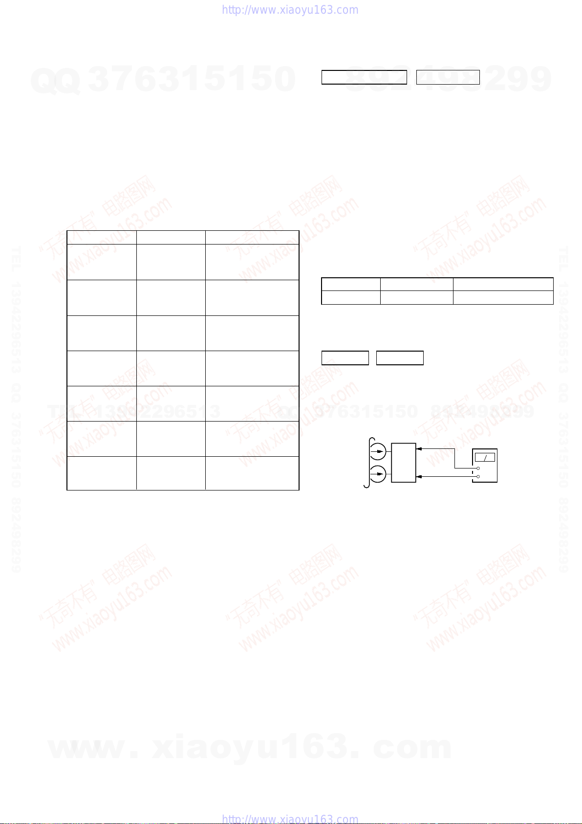
set
MAIN board
IC101
Pin
wk
(L-CH)
Pin
ej
(R-CH)
MAIN board
IC101
Pin
eh
(GND)
+
–
level meter
test tape
P-4-A063
(6.3 kHz, –10 dB)
SECTION 5
MECHANICAL ADJUSTMENTS
HCD-ZX10D
SECTION 6
ELECTRICAL ADJUSTMENTS
PRECAUTION
Q
TEL 13942296513 QQ 376315150 892498299
1. Clean the following parts with a denatured alcohol-moistened
Q
swab:
record/playback heads pinch rollers
erase head rubber belts
capstan idlers
2. Demagnetize the record/playback head with the a head
demagnetizer.
3. Do not use a magnetized screwdriver for the adjustments.
4. After the adjustments, apply suitable locking compound to the
parts adjusted.
5. The adjustments should be performed with the rated power
supply voltage unless otherwise noted.
TORQUE MEASUREMENT
FWD
FWD
back tension
REV
REV
back tension
FF/REW
TEL
FWD tension
REV tension
3
Mode
7
6
Tor que meter
1
3
CQ-102C
CQ-102C
CQ-102RC
CQ-102RC
CQ-201B
13942296513
CQ-403A
CQ-403R
5
1
5
0
Meter reading
3.06 N • m to 6.96 N • m
31 to 71 g • cm
(0.43 – 0.98 oz • inch)
0.19 N • m to 0.58 N • m
2 to 6 g • cm
(0.02 – 0.08 oz • inch)
3.06 N • m to 6.96 N • m
31 to 71 g • cm
(0.43 – 0.98 oz • inch)
0.19 N • m to 0.58 N • m
2 to 6 g • cm
(0.02 – 0.08 oz • inch)
6.96 N • m to 14.02 N • m
71 to 143 g • cm
(0.98 – 1.99 oz • inch)
9.80 N • m
100 g or more
(3.53 oz or more)
9.80 N • m
100 g or more
(3.53 oz or more)
Q
Q
DECK SECTION
1. Demagnetize the record/playback head with a head
demagnetizer.
2. Do not use a magnetized screwdriver for the adjustments.
3. After the adjustments, apply suitable locking compound to the
parts adjust.
4. The adjustments should be performed with the rated power
supply voltage unless otherwise noted.
5. The adjustments should be performed in the order given in this
service manual. (As a general rule, playback circuit adjustment
should be completed before performing recording circuit
adjustment.)
6. The adjustments should be performed for both L-CH and RCH.
7. Switches and controls should be set as follows unless otherwise
specified.
•Test Tape
P-4-A063 6.3 kHz, –10 dB Azimuth Adjustment
RECORD/PLAYBACK HEAD AZIMUTH ADJUSTMENT
DECK A DECK B
Note: Perform this adjustments for both decks
Procedure:
1. Mode: Playback
7
3
2
9
8
Tape Signal Used for
0
5
1
5
1
3
6
9
8
9
2
0 dB=0.775 V
4
8
4
2
9
8
2
9
9
9
TEL 13942296513 QQ 376315150 892498299
9
w
w
w
.
xia
o
y
u
1
6
3
.
c
o
m
27
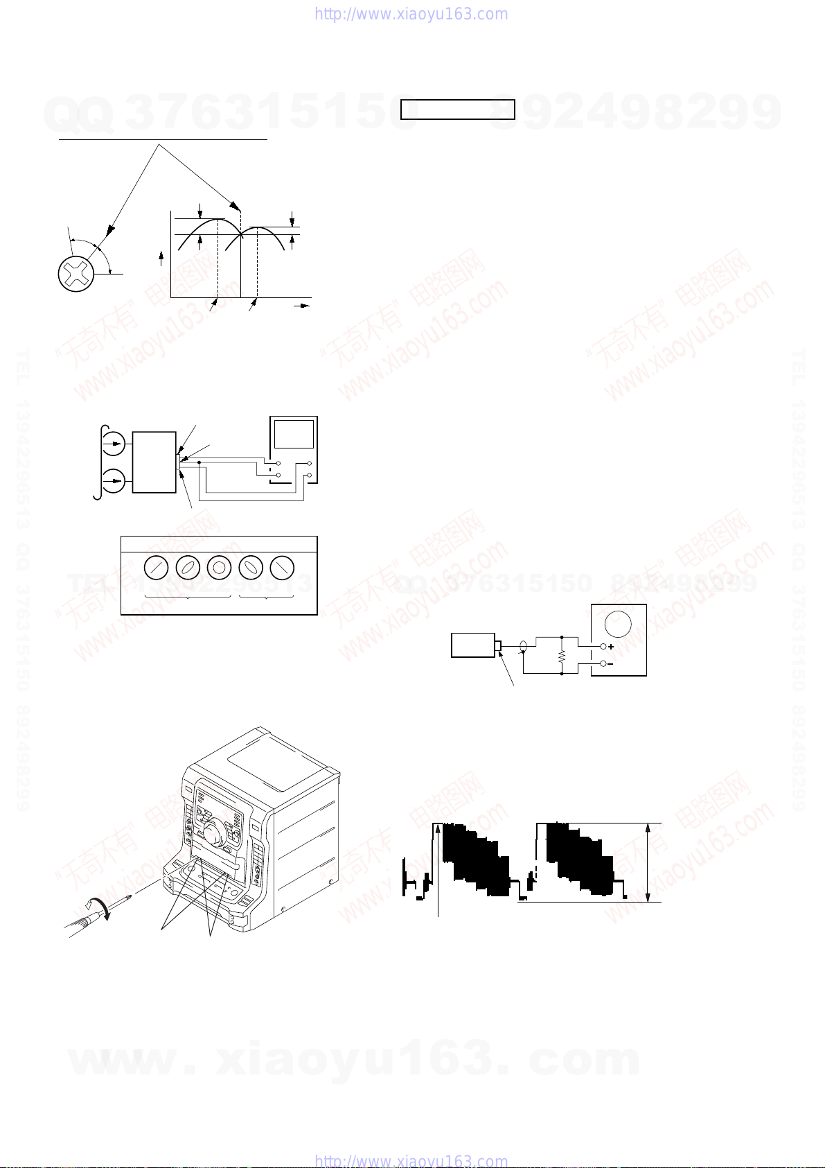
HCD-ZX10D
e
e
2. Turn the adjustment screw and check output peaks. If the peaks
do not match for L-CH and R-CH, turn the adjustment screw
Q
Q
so that outputs match within 1dB of peak.
L-CH
peak
R-CH
Screw
position
TEL 13942296513 QQ 376315150 892498299
3. Mode: Playback
peak
test tape
P-4-A063
(6.3 kHz, –10 dB)
7
3
Output
level
L-CH
MAIN
board
IC101
R-CH
6
within
1dB
L-CH
peak
pin
wk
pin
L
R
ej
pin
waveform of oscilloscope
3
R-CH
peak
eh
1
5
oscilloscop
V
1
within
1dB
Screw
position
H
5
DVD SECTION
0
About the dicision to pass or fail of the optical pick-up block, refer
to “DICISION TO PASS OR FAIL OF THE OPTICAL PICK-UP
BLOCK” (Refer to page 6 in SERVICING NOTES)
• Precaution
1. DVD block is basically designed to operate without
adjustment. Therefore, check each item in order given.
2. Use DVD reference disc unless othermise indicated.
[DVD reference disc]
TDV-520CSO (DVD-SL) : PART No. J-2501-236-A
LUV-P01 (CD) : PART No. 4-999-032-01
TDV-540C (DVD-DL) : PART No. J-2501-235-A
Note: Do not use exiting test disc for DVD.
3. Use an oscilloscope with more than 10MW impedance.
4. Clean the object lens by an applicator with neutral detergent
when the signal level is low than specified value with the
following checks.
AUTO SERVO ADJUSTMENT
After parts related to the servo circuit (RF amplifier (IC001), DSP
(IC509), motor driver (IC501), EEPROM (IC903) so on) are
replaced, re-adjusting the servo circuit is necessary. Select “ALL”
at “1. Drive Auto Adjustment” (Refer to page 19 in TEST MODE)
and adjust DVD-SL (single layer), CD and DVD-DL (dual layer).
VIDEO LEVEL CHECK
Purpose:
This adjustment is made to satisfy the NTSC standard, and if not
adjusted correctly, the brightness will be too large or small.
8
9
2
4
9
8
2
9
9
TEL 13942296513 QQ 376315150 892498299
TEL
4. After the adjustments, apply suitable locking compound to the
pats adjusted.
Adjustment Location: Playback Head (Deck A).
in phase 45°90°135°180
13942296513
good
Record/Playback/Erase Head (Deck B).
forward
reverse
°
wrong
Q
set
VIDEO board
VIDEO OUT jack (J1201)
Procedure:
1. Connect an oscilloscope to VIDOE OUT jack (J1201) on the
VIDEO board.
2. Load a DVD reference disc playback.
3. Check the video signal level is 1.00 ± 0.05 Vp-p.
(WHITE 100%)
75
Oscilloscop
Ω
1.00 ± 0.05 Vp-p
9
4
2
9
8
0
5
1
5
1
3
6
7
3
Q
8
2
9
9
28
w
w
w
.
xia
o
y
u
1
6
3
.
c
o
m
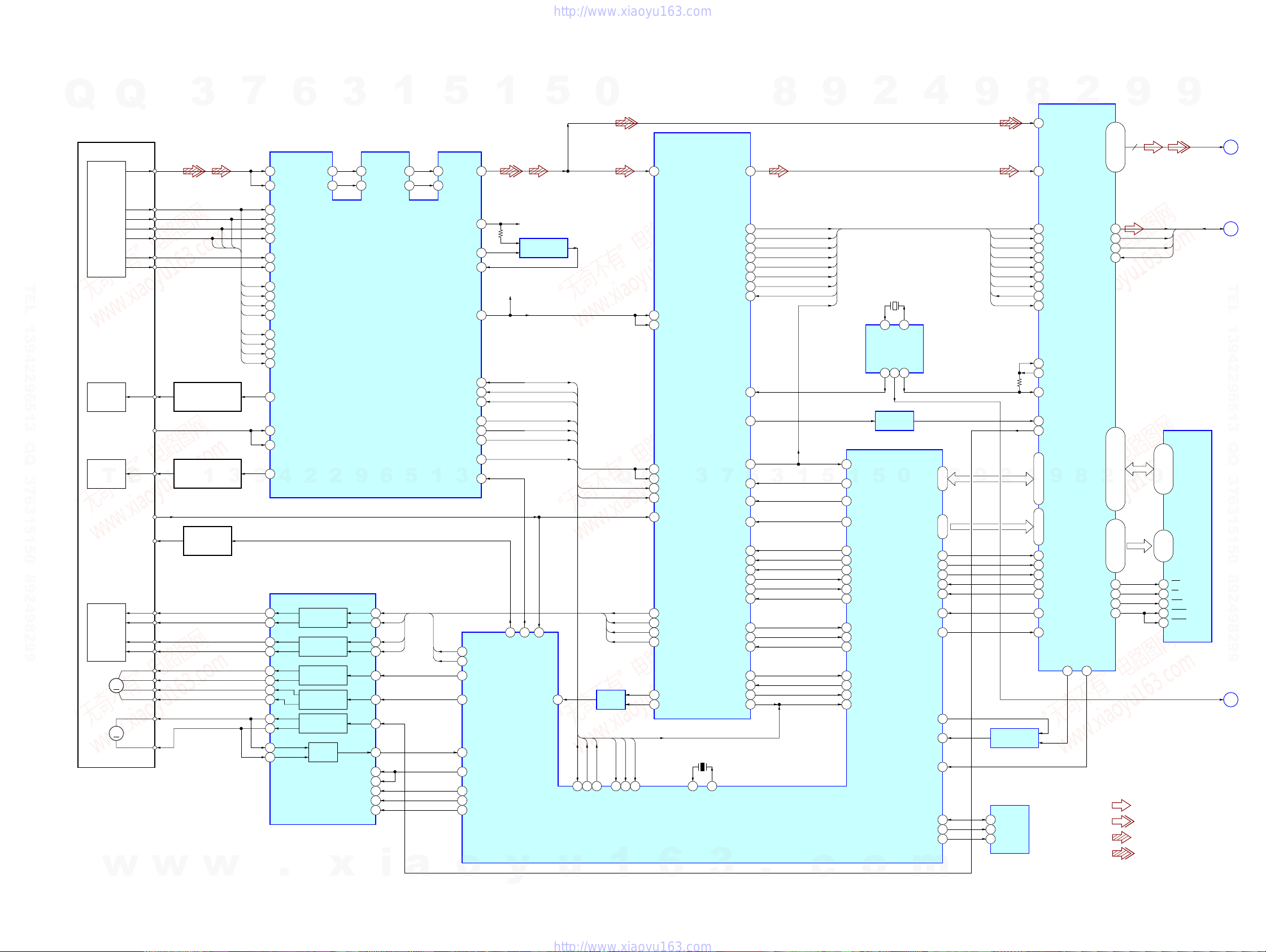
7-1. BLOCK DIAGRAM – RF SERVO SECTION –
Q
Q
RF
3
7
1
63 61
6
DVDRFP
RFSINBATON
SECTION 7
DIAGRAMS
3
62
ATOP
59
AIP
60
AIN
1
53
FNP
52
FNN
5
54
55
DIP
DIN
RFAC
57
1
5
0
50
RFAC
PCMD
HCD-ZX10D
RFIN
MDAT
2
9
32, 30, 27, 24
HDB0 – HDB7
44, 41, 39, 35,
9
8
SD0 – SD7
A
(Page 30)
8
66
9
2
4
9
8
117
160
A
DETECTOR
B
C
D
F
E
D
CBA
TEL 13942296513 QQ 376315150 892498299
OPTICAL TRAVERSE
UNIT
(DBU-3)
LASER
(FOR CD)
LASER
(FOR DVD)
DEVICE
FOCUS/
TRACKING
SLED
SPINDLE
DIODE
DIODE
T
2AXIS
COIL
MM
M
w
CD LD
PD
DVD LD
E
INLIM
SW
FCS+
FCS–
TRK+
TRK–
SLEDA+
SLEDA–
SLEDB+
SLEDB–
SPDL+
SPDL–
AUTOMATIC POWER
AUTOMATIC POWER
CONTROL (FOR DVD)
L
w
CONTROL (FOR CD)
Q002
1
Q001
LASER DIODE
SELECT SWITCH
Q901
w
3
3
A2
4
B2
5
C2
6
D2
18
CD_E
17
CD_F
12
A
A
11
B
D
10
C
C
9
D
B
16
CD_A
A
15
CD_B
D
14
CD_C
C
13
CD_D
22
CDLD
24
CDPD
23
DVDPD
21
DVDLD
9
4
FOCUS/TRACKING COIL DRIVER,
SPINDLE/SLED MOTOR DRIVER
36
37
34
35
32
31
30
29
27
28
47
46
.
FOCUS/TRACKING ERROR AMP
2
2
IC501
FOCUS COIL
DRIVE
TRACKING COIL
DRIVE
SLED MOTOR
DRIVE
SLED MOTOR
DRIVE
SPINDLE MOTOR
DRIVE
BUFFER
POWER SAVE
x
CD/DVD RF AMP,
IC001
9
48
1
3
4
7
10
13
45
19
MUTE12
20
MUTE34
21
MUTE5
22
TSD-M
6
FF
FR
TF
TR
i
5
a
1
VC VC
MEVO
MIN
V125
SDATA
SCLK
SDEN
TE
FE
PI
MIRR
LDON
3
FF
7
FCS_JMP_1
FR
8
FCS_JMP_2
44
SLED_B
43
SLED_A
62
FG
60
MUTE_2D
63
SP_ON
73
TDS-M
9739
DSAVE
o
SDEF, XSAK,
1
BCK
LRCK
C2PO
GSCOR
DFCT
WFCK
SBSO
EXCK
SCOR
5
c
CLOCK
GENERATOR
IC906
26
SCOR
1
10
CDSP2
DOCTRL/
3
ISBTEST
98
XDRST
49
DATA_CD
50
CLOK_CD
27
LAT_CD
9
SENS_CD
52
SQSO
54
SQCK
75
LOCK_CD
71
GFS_CD
59
MUTE_CD
30
COUT_CD
72
SCLK_CD
74
FOK_CD
29
MIRR
5
o
X902
27MHz
7 8
XTI
SO3
MO1
10
13 3
BUFFER
IC703 (2/2)
0
XTO
SO2
XRD
XWR
XCS_DVD
INT0_DVD
INT1_DVD
GFS_DVD
XRST_1882
SCK_DSD
MNT1
SDA_EEP
SCL_EEP
WP_EEP
m
D0 – D7
A0 – A7
JIT
85
84
12
22
23
58
25
45
64
6
5
100
99
8
14 – 21
89 – 96
20
COMPARATOR
AVC
76
LDSEL
y
28
LDON
IC003
DATA RF
CLK RF
SDEN
PI/CE
MIRR
31
INLIM
SLED
TE
FE
61
u
TE
FE
PI/CE
CLKRF
DATA RF
82
83
SDATA_RF
AMP
IC503
SDEN
2
SDEN
SDCLK_RF
1
Q
FF
FR
TF
TR
TE
65
38
VC
42
CE
CD DECODER,
DIGITAL SERVO PROCESSOR
IC509
41
TE
40
SE
Q
39
43
26
33
34
31
32
29
30
MIRR
FE
PI/CE
67
66
PI
FE
TE
6
3
FE
RFDC
SSTP
FFDR
FRDR
TFDR
TRDR
SFDR
SRDR
X901
20MHz
40 41
XTAL
MECHANISM CONTROLLER
IC901 (1/2)
3
32
31
(1.65V)
36
47
46
48
39
40
38
27
26
7
EXTAL
BCK
LRCK
C2PO
WDCK
DFCT
WFCK
SBSO
EXCK
XTAI
MDP
SCOR
XTSL
MD2
XRST
DATA
CLOK
XLAT
SENS
SQSO
SQCK
LOCK
GFS
MUTE
COUT
SCLK
FOK
MIRR
67
65
14
17
11
10
79
80
71
25
15
6
69
63
2
4
6
5
7
76
77
24
13
3
19
8
22
20
3
.
9
BCK
LRCK
C2PO
GSCOR
DFCT
WFCK
SBSO
EXCK
SCOR
2
COMPARATOR
IC703 (1/2)
EEPROM
IC903
5
SDA
6
SCL
7
WP
158
163
155
146
145
151
148
147
150
167
169
170
137
135
4
172 – 176, 1, 2, 4
5, 7, 9 – 14
17
18
19
20
21
107
164
BCLK
LRCK
C2PO
GSCOR
DFCT
WFCK
SBIN
EXCK
SCOR
DVD DECODER
XTAL
XTL2
XTL1
MDIN2
SPO
9
D0 – D7
A0 – A7
XRD
XWR
XCS
XINT0
XINT1
GFS
XRST
109
IC701
8
APE0
26
HDB8
46
HDRQ
48
XHWR
53
XHAC
2
MDBA – MDBF
MDB0 – MDB9,
66 – 69, 71, 73 – 75, 96, 97,
MA0 – MA9
79, 80, 82 – 87,
76
XMWR
94
XOE
78
XRAS
95
XCAS
MNT1
92
• SIGNAL PATH
SDEF
XSAK
XDCK
XSRQ
9
9
99, 101, 102, 104 – 106
89, 91
: AUDIO
: VIDEO
: CD PLAY
: DVD PLAY
I/O0 – I/O15A0 – A9
2 – 5, 7 – 10,
41 – 44, 46 – 49
16Mbit
D-RAM
IC706
27 – 32
21 – 24,
17
WE
33
OE
18
RAS
34
UCAS
35
LCAS
XDCK, XSRQ
27M
B
(Page 30)
TEL 13942296513 QQ 376315150 892498299
C
(Page 30)
HCD-ZX10D
2929
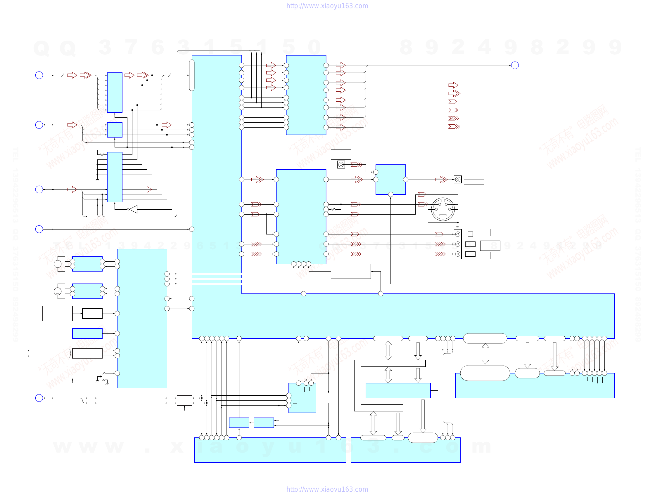
HCD-ZX10D
7-2. BLOCK DIAGRAM – VIDEO/CHANGER SECTION –
LATCH
IC256
LATCH
IC258
LATCH
IC259
7
Q201
6
3
SDEF
XDCK
XSAK
XSRQ
D3V
ADC_DATA
BCK
LRCK
XCK
3
SD0
SD1
SD2
SD3
SD4
SD5
SD6
SD7
BCK
LRCK
Q
A
(Page 29)
B
(Page 29)
Q
8 8
SD0 – SD7
SDEF, XSAK,
XDCK, XSRQ
TEL 13942296513 QQ 376315150 892498299
ADC_DATA, BCK,
LRCK, XCK
D
(Page 32)
1
177 –174, 171 –168
SDDATA0 – SDDATA7
182
SDERROR
183
SDCLK
179
SDEN
178
SDREQ
192
INT/EXT
5
DATA0 (DM)
DATA1 (FLR)
DATA (SLR)
DATA (CSW)
XCK
BCK
LRCK
MDI
MC
ML
VDAC_0
VDAC_1
VDAC_2
1
BCK
XCK
LRCK
150
151
154
155
147
149
148
113
114
115
131
128
125
5
31
DATA4
45
DATA1
46
DATA2
47
DATA3
38
SCKI
40
BCK
41
LRCK
34
MDI
35
MC
36
ML
D/A CONVERTER
VIDEO AMP, 75Ω DRIVER
IC1201
4
CVBSIN
2
CIN
6
YIN
IC302
0
VOUT8
VOUT7
VOUT1
VOUT2
VOUT3
VOUT4
VOUT5
VOUT6
CVBSOUT
C OUT
S-DCOUT
YOUT
20
16
14
13
12
11
10
9
23
26
27
21
J850 (1/2)
GAME INPUT
VIDEO
DML
DMR
FL
FR
SL
SR
C
SW
VIDEO SWITCH, 75Ω DRIVER
3
VIN2
1
VIN1
IC1200
2
VOUT
SW1
8
7
9
CY
2
• SIGNAL PATH
4
DML, DMR, FL, FR, SL, SR, C, SW
: AUDIO
: VIDEO
: Y
: CHROMA
: COMPONENT VIDEO
: GAME INPUT (VIDEO)
J1201
VIDEO OUT
J1202
S VIDEO OUT
9
F
(Page 32)
8
2
9
9
TEL 13942296513 QQ 376315150 892498299
27M
C
(Page 29)
T
M001
(LOADING)
CHUCKING DETECT,
TRAY OPEN/CLOSE DETECT
E
(Page 34)
M
M002
M
(TABLE)
DISC IN
DETECT SENSOR
PH101
(TRAY OPEN/CLOSE DETECT)
I2C DATA, I2C CLK
w
E
L
LOADING MOTOR DRIVE
IC515
4
OUT1
2
OUT29FIN
TABLE MOTOR DRIVE
IC514
4
OUT1
2
OUT29FIN
LEVEL SHIFT
Q870
TABLE SENSOR
PH102
S002
ROTARY ENCODER
S001
OPEN
CLOSE
I2C DATA
I2C CLK
w
FIN
FIN
1
7
7
w
MASTER CONTROLLER
3
9
50
LOD-POS
49
LOD-NEG
48
TBL-POS
47
TBL-NEG
43
DSENS
42
TSENS
45
CHK-SW
44
OC-SW1
46
OC-SW2
IC401 (1/5)
4
.
2
VMUTE2
VMUTE
VIDEO OUT
MREQ
SYS RST
35
36
70
38
37
2
SWITCH
D+3.3V
x
9
IC111
139
XIN
122
5
DRVRX
DRVTX
187
186
33
34
a
SI_ZIVA
SO_ZIVA
1
DRVCLK
184
185
36
35
SCK_ZIVA
VDAC_3
VDAC_4
HIRQ1
SWITCHING
DRVIRQ
3
119
DRVRDY
188
IC904
37
MECHANISM CONTROLLER
o
DRVRDY
SWITCHING
6
110
MREQ
202
RESET
I2C_CL
I2C_DA
160
161
79
78
i
I2C_SIO
I2C_SCL
IC902
y
IC901 (2/2)
10
CYIN
12
CBIN
14
CRIN
MUTE113MUTE225S19I/P
3
107
VS
WRITE_CTRL
HIRQ2
165
116
81
R/B
6
DO
EEPROM
5
DI
IC204
4
SK
u
CYOUT
CBOUT
CROUT
(ZIVA_E2P)
3
CS
WC
1
20
18
Q
Q
16
INTERLACE/PROGRESSIVE
CS (ZIVA_E2P)
191
162
BUFFER
Q202
38
32
CS_ZIVA
3
SELECT SWITCH
Q1200
RST_SPC
HAD0 – HAD15 HA1 – HA3
HAD0 – HAD15 HA1 – HA2
DATA & ADDRESS BUS
HAD0 – HAD15 HA1 – HA3
29 – 36, 38 – 45
RST
6
DQ0 – DQ15
3
1
3
6
7
108
I/P SW
DVD SYSTEM PROCESSOR
IC207
22, 19 – 14, 11 – 3 2, 207, 206
DATA & ADDRESS BUS
ADDRESS LATCH
IC231 – 233
25 – 23
A0 – A2
.
HA1 – HA3HAD0 – HAD15
22 – 18, 8 – 1,48,
17, 16, 9, 10, 13
PROGRAM ROM
IC205
ADDRESS BUS
A3 – A21
5
HA4 – HA22
c
Y
J1200
COMPONENT
PB/C
B
VIDEO OUT
0
5
1
PR/C
R
HCS0
WEH.UDS
HREAD
ALE
195
27
190
OE
CE
CE
OE
28
26
CE
OE
o
57 – 60, 64 – 71, 75 – 78,
25
81 – 84, 88 – 95, 99 – 102
WE
2,4,5,7,8,10,11,13,74,76,77,79,
82,83,85,31,33,34,36,37,39,40,
42,45,47,48,50,51,53,54,56
WE
11
WE
m
8
MD0 – MD31
DQ0 – DQ31
9
2
MA0 – MA11
42 – 33, 45, 46
25 – 27,
60 – 66, 24, 21
A0 – A9,
A10/AP, NC
128Mbit SD-RAM
4
IC203
9
MDQM0 – MDQM3
62, 73, 86, 97
16, 71, 28, 59
DQM0 – DQM3
8
2
48
22
BA0
47
23
BS0
BA1
BS1
9
56
68
MCLK
49
20
CLK
MCS0
53
17
CS
9
MWE
WE
51
19
MRAS
52
18
RAS
MCAS
CAS
HCD-ZX10D
3030
 Loading...