

Sony HCD-ZX80D, HCD-ZX100D Service Manual

HCD-ZX80D/ZX100D
SERVICE MANUAL
Ver. 1.0 2006.05
• HCD-ZX80D is the amplifier, disc player, tape deck
and tuner section in FST-ZX80D/LBT-ZX80D.
• HCD-ZX100D is the amplifier, disc player, tape deck
and tuner section in FST-ZX100D/LBT-ZX100D.
This system incorporates Dolby* Digital, Dolby
Pro Logic (II) adaptive matrix surround decoder,
and the DTS** Digital Surround System.
* Manufactured under license from Dolby
Laboratories.
“Dolby”, “Pro Logic”, and the double-D
symbol are trademarks of Dolby
Laboratories.
**Manufactured under license from Digital
Theater Systems, Inc.
“DTS” and “ DTS Digital Surround” are
registered trademarks of Digital Theater
Systems, Inc.
DVD
Section
Tape deck Model Name Using Similar Mechanism NEW
Section T ape Transport Mechanism T ype CWN42RR603
Photo: HCD-ZX80D
Model Name Using Similar Mechanism NEW
DVD Mechanism Type CDM74HF-DVBU101
Optical Pick-up Block Name KHM-310CAB or KHM-313CAB
SPECIFICATIONS
E Model
Amplifier section
HCD-ZX100D
The following are measured at AC 120, 127, 220,
240V 50/60 Hz
DIN power output (rated): 130 W + 130 W
(6 ohms at 1 kHz, DIN)
Continuous RMS power output (reference)
Front speaker: 170 W + 170 W
(6 ohms at 1 kHz, 10%
THD)
Center speaker: 80 W
(16 ohms at 1 kHz, 10%
THD)
Surround speaker: 170 W + 170 W
(6 ohms at 1 kHz, 10%
THD)
Subwoofer: 180 W (8 ohms at 100 Hz,
10% THD)
HCD-ZX80D
The following are measured at AC 120, 127, 220,
240V 50/60 Hz
DIN power output (rated):155 W + 155 W
(6 ohms at 1 kHz, DIN)
Continuous RMS power output (reference)
Front speaker: 200 W + 200 W
(6 ohms at 1 kHz, 10%
THD)
Center speaker: 80 W
(16 ohms at 1 kHz, 10%
THD)
Surround speaker: 200 W + 200 W
Inputs
VIDEO INPUT (phono jacks):
TV/SAT AUDIO IN L/R (phono jacks):
MIC 1 or 2 (phone jack): Sensitivity 1 mV,
Outputs
AUDIO OUT (phono jacks):
VIDEO OUT (phono jack):
COMPONENT VIDEO OUT:
S VIDEO OUT (4-pin/mini-DIN jack):
(6 ohms at 1 kHz, 10%
THD)
VIDEO: 1 Vp-p, 75 ohms
AUDIO L/R: Voltage
250 mV, impedance 47
kilohms
Voltage 250 mV/450 mV,
impedance 47 kilohms
impedance 10 kilohms
Voltage 250 mV,
impedance 1 kilohm
Max. output level 1 Vp-p,
unbalanced, Sync.
negative load impedance
75 ohms
Y: 1 Vp-p, 75 ohms
B/CB
: 0.7 Vp-p, 75 ohms
P
P
R/CR
: 0.7 Vp-p, 75 ohms
Y: 1 Vp-p, unbalanced,
Sync. negative
C: 0.286 Vp-p, load
impedance 75 ohms
PHONES (stereo mini jack):
FRONT SPEAKER: Use only the supplied
SURR SPEAKER: Use only the supplied
CENTER SPEAKER: Use only the supplied
SUBWOOFER OUT:
HCD-ZX100D:
HCD-ZX80D (phono jacks):
Disc player section
System Compact disc and digital
Laser Semiconductor laser
accepts headphones of
8 ohms or more
speakers
speakers
speaker
Use only the supplied
subwoofer
Voltage 250 mV,
impedance 1 kilohm
audio and video system
(DVD: λ = 650 nm,
CD: λ = 790 nm)
Emission duration:
continuous
– Continued on next page –
DVD DECK RECEIVER
9-887-251-01
2006E05-1
© 2006.05
Sony Corporation
Home Audio Division
Published by Sony Techno Create Corporation

HCD-ZX80D/ZX100D
Frequency response DVD (PCM 48 kHz):
Video color system format
Latin American models: NTSC
Other models: NTSC and PAL
Tape deck section
Recording system 4-track 2-channel stereo
Frequency response 50 – 13,000 Hz (±3 dB),
Tuner section
FM stereo, FM/AM superheterodyne tuner
FM tuner section
Tuning range
Antenna FM lead antenna
Antenna terminals 75 ohms unbalanced
Intermediate frequency 10.7 MHz
AM tuner section
Tuning range
Latin American models: 530 – 1,710 kHz
Russian models:
Other models: 531 – 1,602 kHz
Antenna AM loop antenna
Antenna terminals External antenna terminal
Intermediate frequency 450 kHz
General
Power requirements
Mexican model: 127 V AC, 60 Hz
Other models: 120 V, 220 V or
2 Hz – 22 kHz (±1dB)
CD: 2 Hz – 20 kHz
(±0.5 dB)
using Sony TYPE I tape
87.5 – 108.0 MHz
(50 kHz step)
(with the interval set at
10 kHz)
531 – 1,710 kHz
(with the interval set at
9 kHz)
531– 1,602 kHz
(with the interval set at
9 kHz)
(with the interval set at
9 kHz)
530 – 1,710 kHz
(with the interval set at
10 kHz)
230 – 240 V AC, 50/60 Hz
Adjustable with voltage
selector
Power consumption
HCD-ZX100D
HCD-ZX80D
430 W
390 W
Dimensions (w/h/d) (Approx.)
281 × 379 × 404.5 mm
Mass (Approx.)
16.3 kg
Design and specifications are subject to change
without notice.
SELF DIAGNOSIS FUNCTION
Self-diagnosis Function
(When letters/numbers appear in the
display)
When the self-diagnosis function is activated to
prevent the system from malfunctioning, a
5-character service number (e.g. C 13 50) with a
combination of a letter and 4 digits appears on
the TV screen and the front panel display. In this
case, check the following table.
First 3
characters of
the service
number
C 13 This disc is dirty.
C 31 The disc is not inserted correctly.
E XX
(XX is a
number)
When displaying the version number on the
TV screen
When you turn on the system, the version
number [VER.X.XX] (X is a number) may
appear on the TV screen. Although this is not a
malfunction and for Sony service use only,
normal system operation will not be possible.
Turn off the system, and then turn on the system
again to operate.
Notes on chip component replacement
• Never reuse a disconnected chip component.
• Notice that the minus side of a tantalum capacitor may be
Flexible Circuit Board Repairing
• Keep the temperature of the soldering iron around 270 ˚C
• Do not touch the soldering iron on the same conductor of the
• Be careful not to apply force on the conductor when soldering
Cause and corrective action
•Clean the disc with a soft cloth.
• Restart the system, then re-insert
the disc correctly.
To p revent a malfunction, the system
has performed the self-diagnosis
function.
• Contact your nearest Sony dealer or
local authorized Sony service
facility and give the 5-character
service number.
Example: E 61 10
VER.X.XX
damaged by heat.
during repairing.
circuit board (within 3 times).
or unsoldering.
SAFETY-RELATED COMPONENT WARNING!!
COMPONENTS IDENTIFIED BY MARK 0 OR DOTTED LINE
WITH MARK 0 ON THE SCHEMATIC DIAGRAMS AND IN
THE PARTS LIST ARE CRITICAL TO SAFE OPERATION.
REPLACE THESE COMPONENTS WITH SONY P AR TS WHOSE
PART NUMBERS APPEAR AS SHOWN IN THIS MANU AL OR
IN SUPPLEMENTS PUBLISHED BY SONY.
2
CAUTION
Use of controls or adjustments or performance of procedures
other than those specified herein may result in hazardous radiation
exposure.
This appliance is
classified as a CLASS 1
LASER product. This
label is located on the
rear exterior.
The following caution label is located inside the
apparatus.

TABLE OF CONTENTS
HCD-ZX80D/ZX100D
1. SERVICING NOTES ............................................... 4
2. GENERAL ................................................................... 6
3. DISASSEMBLY
3-1. Disassembly Flow ........................................................... 8
3-2. Case ................................................................................. 9
3-3. Escution Top Block ......................................................... 9
3-4. Loading Panel .................................................................. 10
3-5. Tuner (FM/AM) (TM10SE) ............................................ 10
3-6. DVD Mechanism Deck Block......................................... 11
3-7. Front Panel Block ............................................................ 11
3-8. Back Panel Block ............................................................ 12
3-9. MAIN Board Block ......................................................... 12
3-10. MAIN Board.................................................................... 13
3-11. Cover (CDM)................................................................... 13
3-12. DRIVER Board, SW Board............................................. 14
3-13. Optical Pick-Up Block
(KHM-310CAB or KHM-313CAB) ............................... 14
3-14. SENSOR Board ............................................................... 15
3-15. MOTOR (TB) Board ....................................................... 15
3-16. MOTOR (LD) Board ....................................................... 16
4. TEST MODE .............................................................. 17
5. MECHANICAL ADJUSTMENTS ....................... 21
6. ELECTRICAL ADJUSTMENTS ......................... 21
7-15. Printed Wiring Board – VIDEO Board –......................... 38
7-16. Schematic Diagram – VIDEO Board – ........................... 39
7-17. Printed Wiring Board – MIC Board – ............................. 40
7-18. Schematic Diagram – MIC Board – ................................ 41
7-19. Printed Wiring Board – EFFECTOR Board – ................. 42
7-20. Schematic Diagram – EFFECTOR Board –.................... 43
7-21. Printed Wiring Board – KARAOKE Board – ................. 44
7-22. Schematic Diagram – KARAOKE Board – .................... 44
7-23. Printed Wiring Board – MAIN Board – .......................... 45
7-24. Schematic Diagram – MAIN Board (1/6) – .................... 46
7-25. Schematic Diagram – MAIN Board (2/6) – .................... 47
7-26. Schematic Diagram – MAIN Board (3/6) – .................... 48
7-27. Schematic Diagram – MAIN Board (4/6) – .................... 49
7-28. Schematic Diagram – MAIN Board (5/6) – .................... 50
7-29. Schematic Diagram – MAIN Board (6/6) – .................... 51
7-30. Printed Wiring Board – PA Board – ................................ 52
7-31. Schematic Diagram – PA Board –................................... 53
7-32. Printed Wiring Board – SURROUND Board – ............... 55
7-33. Schematic Diagram – SURROUND Board (1/2) – ......... 56
7-34. Schematic Diagram – SURROUND Board (2/2) – ......... 57
7-35. Printed Wiring Board – PANEL Board – ........................ 58
7-36. Schematic Diagram – PANEL Board – ........................... 59
7-37. Printed Wiring Boards – FRONT KEY Section – ........... 60
7-38. Schematic Diagram – FRONT KEY Section – ............... 61
7-39. Printed Wiring Boards – TOP KEY Section – ................ 62
7-40. Schematic Diagram – TOP KEY Section –..................... 63
7-41. Printed Wiring Board – TRANSFORMER Board – ....... 64
7-42. Printed Wiring Board – PRIMARY Board – ................... 65
7-43. Schematic Diagram – POWER SUPPLY Section – ........ 66
7. DIAGRAMS
7-1. Block Diagram – RF SERVO/VIDEO Section – ............ 23
7-2. Block Diagram – MIC/EFFECTOR Section – ................ 24
7-3. Block Diagram – TUNER/TAPE Section – .................... 25
7-4. Block Diagram – AUDIO Section – ................................ 26
7-5. Block Diagram – AMP Section – .................................... 27
7-6. Block Diagram
– PANEL/POWER SUPPLY Section – ........................... 28
7-7. Printed Wiring Board – DMB15 Board (Side A) – ......... 30
7-8. Printed Wiring Board – DMB15 Board (Side B) – ......... 31
7-9. Schematic Diagram – DMB15 Board (1/4) –.................. 32
7-10. Schematic Diagram – DMB15 Board (2/4) –.................. 33
7-11. Schematic Diagram – DMB15 Board (3/4) –.................. 34
7-12. Schematic Diagram – DMB15 Board (4/4) –.................. 35
7-13. Printed Wiring Boards – CHANGER Section –.............. 36
7-14. Schematic Diagram – CHANGER Section – .................. 37
8. EXPLODED VIEWS
8-1. Case, Escutcheon Top Section ......................................... 81
8-2. PANEL Board Section..................................................... 82
8-3. Tape Mecha Deck Section............................................... 83
8-4. Back Panel Section .......................................................... 84
8-5. DMB15/KARAOKE/VIDEO Boards Section................. 85
8-6. MAIN/PA/SURROUND Boards Section ........................ 86
8-7. Power Transformer Section ............................................. 87
8-8. DVD Mechanism Deck Section-1
(CDM74HF-DVBU101).................................................. 88
8-9. DVD Mechanism Deck Section-2
(CDM74HF-DVBU101).................................................. 89
9. ELECTRICAL PARTS LIST................................ 90
3
HCD-ZX80D/ZX100D
Model number label
B
B
SECTION 1
SERVICING NOTES
NOTES ON HANDLING THE OPTICAL PICK-UP
BLOCK OR BASE UNIT
The laser diode in the optical pick-up block may suffer electrostatic
break-down because of the potential difference generated by the
charged electrostatic load, etc. on clothing and the human body.
During repair, pay attention to electrostatic break-down and also
use the procedure in the printed matter which is included in the
repair parts.
The flexible board is easily damaged and should be handled with
care.
NOTES ON LASER DIODE EMISSION CHECK
The laser beam on this model is concentrated so as to be focused on
the disc reflective surface by the objective lens in the optical pickup block. Therefore, when checking the laser diode emission,
observe from more than 30 cm away from the objective lens.
UNLEADED SOLDER
Boards requiring use of unleaded solder are printed with the leadfree mark (LF) indicating the solder contains no lead.
(Caution: Some printed circuit boards may not come printed with
the lead free mark due to their particular size)
: LEAD FREE MARK
Unleaded solder has the following characteristics.
• Unleaded solder melts at a temperature about 40 °C higher
than ordinary solder.
Ordinary soldering irons can be used but the iron tip has to be
applied to the solder joint for a slightly longer time.
Soldering irons using a temperature regulator should be set to
about 350 °C.
Caution: The printed pattern (copper foil) may peel away if
the heated tip is applied for too long, so be careful!
• Strong viscosity
Unleaded solder is more viscou-s (sticky, less prone to flow)
than ordinary solder so use caution not to let solder bridges
occur such as on IC pins, etc.
• Usable with ordinary solder
It is best to use only unleaded solder but unleaded solder may
also be added to ordinary solder.
RELEASING THE DVD TRAY LOCK
The disc tray lock function for the antitheft of an demonstration
disc in the store is equipped.
Releasing Procedure :
1. Press the
I/1 button to turn the power on.
2. Press the DVD button to select “DVD”.
3. While pressing the x button, press the Z OPEN/CLOSE button
until “UNLOCKED” displayed on the fluorescent indicator
tube (around 5 seconds).
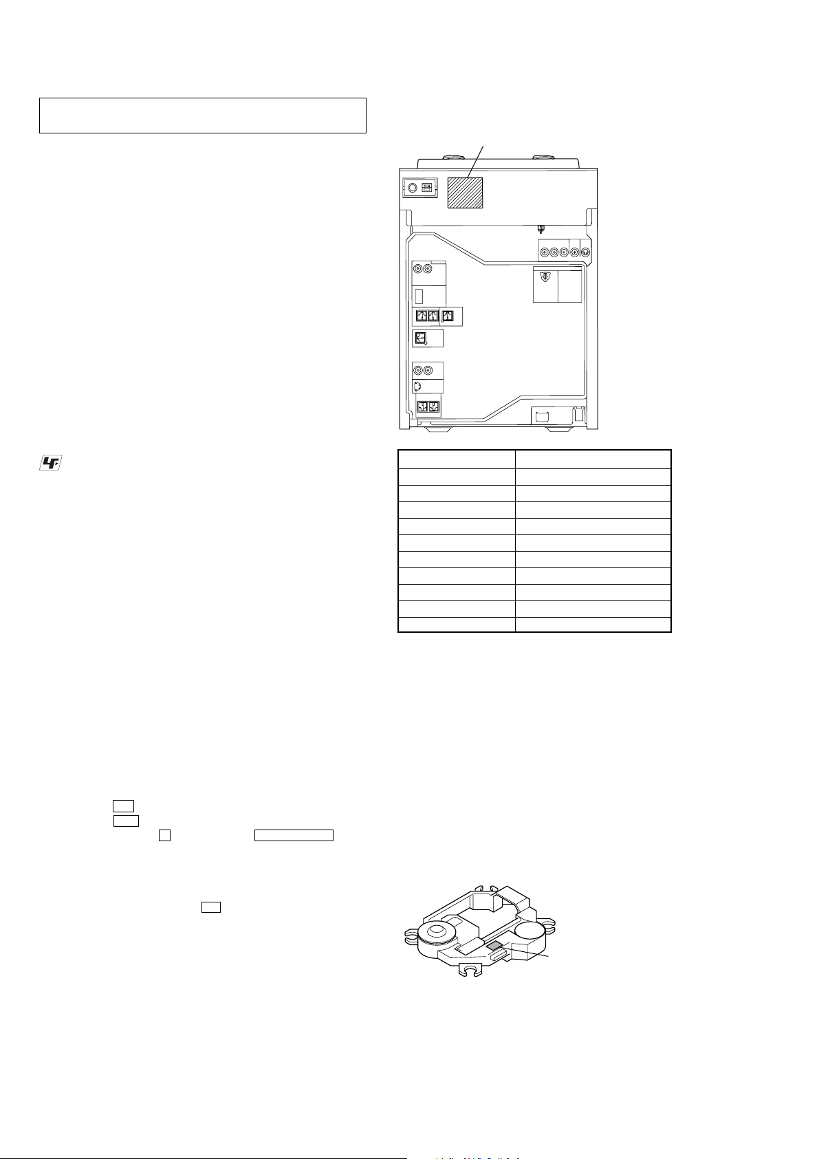
MODEL IDENTIFICATION
– Back Panel –
Label indication Model
2-661-760-5[] E2 ZX80D: E2
2-661-760-6[] E2 ZX100D: E2
2-661-761-3[] MX ZX100D: MX
2-661-761-4[] MX ZX80D: MX
2-672-142-0[] E3 ZX100D: E3
2-672-142-1[] E3 ZX80D: E3
2-675-973-2[] E51 ZX80D: E51
2-675-973-3[] E51 ZX100D: E51
2-686-974-1[] SP2/6 ZX100D: SP, MY
2-686-106-0[] E13 ZX80D: E13
• Abbreviation
E2 : 120V AC area in E model
E3 : 240V AC area in E model
E13 : Russian model and 220V – 230V AC area in E model
E51 : Chilean and Peruvian models
MX : Mexican model
MY : Malaysia model
SP : Singapore model
HOW TO IDENTIFY OPTICAL PICK-UP BLOCK
There are two kinds of OPTICAL PICK-UP BLOCK in this set.
When replacing the OPTICAL PICK-UP BLOCK, make sure which
OPTICAL PICK-UP BLOCK it is following the “How to Identify”
in the figure shown below.
Printed of KHM-310CAB or KHM-313CAB.
Note: When “LOCKED” is displayed, the disc tray lock is not released by
turning power on/off with the I/1 button.
NOTES ON REPLACEMENT OF THE DMB15 BOARD
New part of EEPROM (IC103) on the DMB15 board cannot be
used. Therefore, if the mounted DMB15 board is replaced, exchange
new EEPROM with that used before the replacement.
4
KHM-310CA
or
KHM-313CA

Playable discs
DVD DECK RECEIVER
MODELN0. HCD-ZX100D
SERIAL NO.
AC:120-127/220/230-240V 50/60Hz430W
You can play back the following discs on this
system. Other discs cannot be played back.
List of playable discs
Format of discs Disc logo
DVD VIDEO
DVD-RW/DVD-R
DVD+RW/
DVD+R
VIDEO CD
AUDIO CD
CD Graphics
(CDG)
(Latin American
models only)
CD-R/CD-RW
“DVD+RW”, “DVD-RW”, “DVD+R”,
“DVD VIDEO”, and the “CD” logos are
trademarks.
Notes on discs
The system can play back the following disc:
• CD-ROMs/CD-Rs/CD-RWs recorded in the
following formats:
– VIDEO CD format
– AUDIO CD format
– CD Graphics (Latin American models
only)
– DATA CD format which contains MP3
audio tracks, JPEG image files and DivX
video files of format conforming to ISO
9660 Level 1, Level 2 or Joliet in
expansion format
• DVD-ROMs/DVD-Rs/DVD-RWs/DVD+Rs/
DVD+RWs recorded in the following
formats:
– DVD VIDEO format
– DATA DVD format which contains MP3
audio tracks, JPEG image files and DivX
video files of format conforming to UDF
(Universal Disk Format)
– VR (Video Recording) format (DVD-Rs/
DVD-RWs only)
The system cannot play back the following
discs:
• CD-ROMs recorded in PHOTO CD format
• Data part of CD-Extras
• Data part of Mixed CDs
• Super Audio CDs
• DVD Audio discs
• DVD-RAMs
•A DVD VIDEO with a different region code.
•A disc that has a non-standard shape (e.g.,
heart, square, star).
•A disc that has the adhesive cellophane tape
or a sticker still left on it.
HCD-ZX80D/ZX100D
1)
MP3 audio tracks must be in MPEG 1 Audio
Layer 3 format.
2)
DivX video files must be recorded in DivX format
with the extension “.AVI” or “.DIVX”.
3)
ISO 9660 Format
A logical format of files and folders on CD-ROMs,
defined by ISO (International Organization for
Standardization).
4)
CD-Extra: This format records audio (AUDIO CD
data) on the tracks in session 1 and data on the tracks
in session 2.
5)
Mixed CD: This format records data on the first track
and audio (AUDIO CD data) on the second and
subsequent tracks of a session.
Region code of DVD VIDEOs
you can play back on this
system
Your system has a region code printed on the
back of the unit and will only play back DVD
VIDEOs labeled with identical region code.
DVD VIDEOs labeled will also be played
ALL
back on this system.
If you try to play back any other region code
DVD VIDEO, the message “Playback
prohibited by area limitations.” will appear on
the TV screen. Depending on the DVD VIDEO,
no region code indication may be labeled even
though playing the DVD VIDEO is prohibited
by area restrictions.
Example:
Region code
Note on DualDiscs
A DualDisc is a two sided disc product which
mates DVD recorded material on one side with
digital audio material on the other side.
However, since the audio material side does not
conform to Compact Disc (CD) standard,
playback on this product is not guaranteed.
Notes on CD-R/CD-RW/DVD-R/
DVD-RW/DVD+R/DVD+RW
1)
2)
3)
1)
2)
4)
5)
• In some cases, CD-Rs/CD-RWs/DVD-Rs/
DVD-RWs/DVD+Rs/DVD+RWs cannot be
played back on this system due to the
recording quality or physical condition of the
disc, or the characteristics of the recording
device and authoring software. The disc will
not be played back if it has not been correctly
finalized. For more information, see the
operation instructions for the recording
device.
• Note that some playback functions may not
work with some DVD+RWs/DVD+Rs, even
if they have been correctly finalized. In this
case, view the disc by normal playback.
•A disc created in Packet Write format cannot
be played back.
Note on playback operations
of DVD VIDEOs and VIDEO
CDs
Some playback operations of DVD VIDEOs and
VIDEO CDs may be intentionally set by
software producers. Since this system play back
DVD VIDEOs and VIDEO CDs according to
the disc contents the software producers
designed, some playback features may not be
available. Also, refer to the instructions supplied
with the DVD VIDEOs or VIDEO CDs.
Note on PBC (Playback
Control) (VIDEO CDs)
This system conforms to Ver. 1.1 and Ver. 2.0 of
VIDEO CD standards. You can enjoy two kinds
of playback depending on the disc type.
Disc type You can
VIDEO CDs
without PBC
functions
(Ver. 1.1 discs)
Disc type You can
VIDEO CDs
with PBC
functions
(Ver. 2.0 discs)
Enjoy video playback (moving
pictures) as well as music.
Play back interactive software
using menu screens displayed on
the TV screen (PBC Playback), in
addition to the video playback
functions of Ver. 1.1 discs.
Moreover, you can play back highresolution still pictures, if they are
included on the disc.
Music discs encoded with
copyright protection
technologies
This product is designed to play back discs that
conform to the Compact Disc (CD) standard.
Recently, various music discs encoded with
copyright protection technologies are marketed
by some record companies. Please be aware that
among those discs, there are some that do not
conform to the CD standard and may not be
playable by this product.
Notes on Multi Session disc
• This system can play back Multi Session discs
when an MP3 audio track is contained in the
first session. Any subsequent MP3 audio
tracks recorded in later sessions can also be
played back.
• This system can play back Multi Session discs
when a JPEG image file is contained in the
first session. Any subsequent JPEG image
files recorded in later sessions can also be
played back.
• If the first session is recorded in AUDIO CD
or VIDEO CD format, only the first session
will be played back.
•The system will recognize a Multi Session
disc as an AUDIO CD if there is a session
recorded in AUDIO CD format on the disc.
However, the system will only play back the
disc if the first session is recorded in AUDIO
CD format.
•With DATA CD or DATA DVD, the system
will only play back DivX video files even if it
contains MP3 audio tracks or JPEG image
files.
5

HCD-ZX80D/ZX100D
w
w
wdwfw
w
w
tstat;r
LOCATION OF CONTROLS
Unit
ALPHABETICAL ORDER
A – D
AMP MENU e;
BALANCE rh
BEAT JUMP rs
BEAT MAX ra
BEAT PAD r;
CD SYNC q;
CHORUS wl
Deck A ea
Deck B qk
DELAY wk
DIRECTION ql
DISC 1 ~ 3 ts
Disc tray 8
DISPLAY 2
Display 6
DVD ej
E – L
ECHO LEVEL ws
ENTER wa
EQ BAND w;
EX-CHANGE/DISC SKIP t;
FADER rg
FLANGER 3
GROOVE qh
ILLUMINATION 1
IR Receptor ek
SECTION 2
GENERAL
M – R
MASTER VOLUME wf
MIC 1/2 (jack) wg
MIC 1/2 LEVEL wd
OPERATION DIAL ta
PHONES (jack) wj
Power illuminator 5
PRESET +/– qf
PROGRESSIVE 7
RANDOM rd
REC PAUSE/START 9
S – Z
SOUND FIELD 4
SPEAKERS rj
TAPE A/B eg
TUNER/BAND eh
TUNING +/– qg
TV/SAT ef
VIDEO INPUT (jacks) wh
VIDEO ed
X-ROUND JOG rk
X-ROUND OFF rj
WAVE rf
SYMBOLS
?/1 (on/standby) el
Z OPEN/CLOSE rl
nN (play) qa
.> (go backward/forward) qf
mM (rewind/fast forward) qg
X (pause) qs
x (stop) qd
A Z (Eject A) es
B Z (Eject qj
This section is extracted from
instruction manual.
Front Panel
el
ek
ej
eh
eg
ef
ed
es
ea
e;
wl
wk
Top Panel
34 5678
12
h
j
9
q;
qa
qs
qd
qf
qg
qh
qj
qk
ql
w;
a
rg
s
rjrh
rk
g
rdrsrar;
rf
6
l

Remote control
HCD-ZX80D/ZX100D
ALPHABETICAL ORDER
A – L
ADVANCE wf
ALBUM +/– qa
ANGLE q;
AUDIO 8
CLEAR wk
DISC SKIP 3
DISPLAY ed
ENTER wh
FM MODE 7
FUNCTION +/– 4
KARAOKE MODE ea
KARAOKE PON e;
KEY CONTROL #/2 es
M – S
MENU qs
Numeric Buttons
PICTURE NAVI 6
PRESET + qh
PRESET – wd
REPEAT 7
REPLAY wf
SCORE 5
SLEEP eg
SLOW qj
SLOW ws
SOUND FIELD qd
STEP C wf
SUBTITLE 9
1)
wl
T – Z
THEATRE SYNC 1
TIMER MENU eh
TIME/TEXT ef
TOP MENU wj
TUNING + qj
TUNING – ws
TV w;
TV CH + qh
TV CH – wd
TV/VIDEO eg
TV VOL +/– qf
TV &/1 (on/standby) 2
VOLUME +/– qf
NUMBERS AND SYMBOLS
?/1 (on/standby) 2
x (stop) qk
X (pause) ql
H
> (go forward) qh
. (go backward) wd
M (fast forward) qj
m (rewind) ws
1)
(play) wa
1)
1)
V/v/B/b wh
10/0 wl
-/-- wk
O RETURN wg
DISPLAY qg
c STEP wf
1)
The numeric button 5, TV VOL
+, VOLUME + and H
buttons have a tactile dot. Use
the tactile dot as a reference
when operating the system.
eh
eg
ef
ed
es
ea
e;
wl
wk
wj
wh
wg
wf
wd
ws
wa
w;
1
3
5
7
9
qa
qd
qf
qh
qk
2
4
6
8
q;
qs
qg
qj
ql
Setting the clock
1
Press ?/1 to turn on the system.
2
Press TIMER MENU.
The hour indication flashes in the display.
3
Press V or v repeatedly to set the
hour.
4
Press ENTER.
The minute indication flashes in the
display.
5
Press V or v repeatedly to set the
minute.
6
Press ENTER.
The clock starts functioning.
To adjust the clock
1
Press TIMER MENU.
“PLAY SET?” flashes in the display.
2
Press V or v repeatedly to select “CLOCK
SET?”, then press ENTER.
The hour indication flashes in the display.
3
Do the same procedures as step 3 to 6
above.
Notes
• The clock settings are canceled when you disconnect
the power cord or if a power failure occurs.
•You cannot set the clock in Power Saving Mode.
7

HCD-ZX80D/ZX100D
SECTION 3
DISASSEMBLY
• This set can be disassembled in the order shown below.
3-1. DISASSEMBLY FLOW
Note 1: The process described in can be performed in any order.
Note 2: Without completing the process described in , the next process can not be performed.
SET
3-2. CASE
(Page 9)
3-3. ESCUTCHEON TOP BLOCK
(Page 9)
3-5. TUNER (FM/AM) (TM10SE)
(Page 10)
3-6. DVD MECHANISM DECK BLOCK
(Page 11)
3-7. FRONT PANEL BLOCK
(Page 11)
3-8. BACK PANEL BLOCK
(Page 12)
3-9. MAIN BOARD BLOCK
(Page 12)
3-4. LOADING PANEL
(Page 10)
3-11. COVER (CDM)
(Page 13)
3-12. DRIVER BOARD,
SW BOARD
(Page 14)
3-14. SENSOR BOARD
(Page 15)
3-15. MOTOR (TB) BOARD
(Page 15)
3-10. MAIN BOARD
(Page 13)
8
3-13. OPTICAL PICK-UP BLOCK
(KHM-310CAB or KHM-313CAB)
(Page 14)
3-16. MOTOR (LD) BOARD
(Page 16)
Note: Follow the disassembly procedure in the numerical order given.
)
s
HCD-ZX80D/ZX100D
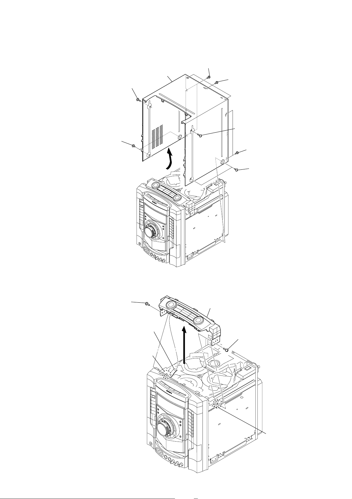
3-2. CASE
3
screw
(case 3 TP2)
4
two screws
(case 3 TP2)
5
case
2
two screws
(BVTP 3
×
10)
1
three screws
(BVTP 3
3
screw (case 3 TP2
2
4
×
10)
two screws
(BVTP 3
two screws
(case 3 TP2)
×
10)
3-3. ESCUTCHEON TOP BLOCK
1
screw
(BVTP 3
3
×
12)
wire (flat type) (7 core)
(CN1153)
2
boss
4
escutcheon top block
1
screw
(BVTP 3
×
12)
2
bos
9

HCD-ZX80D/ZX100D
)
3-4. LOADING PANEL
3
four claws
1
Turn the gear (loading A)
to the direction of the arrow.
2
loading panel
4
3-5. TUNER (FM/AM) (TM10SE)
3
tuner (FM/AM) (TM10SE)
2
two
(BVTT 3
1
wire (flat type) (9 core)
screws
×
8
10
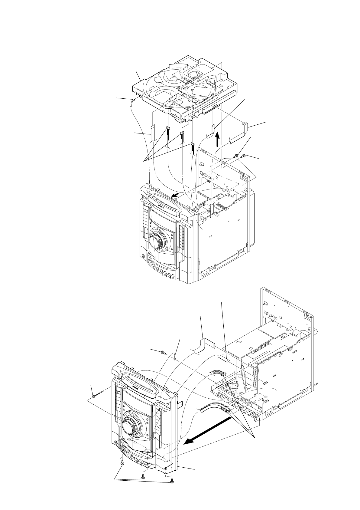
3-6. DVD MECHANISM DECK BLOCK
8
DVD mechanisim deck block
4
connector
(CN802)
3
wire (flat type) (21 core)
(CN302)
4
three
connectors
(CN401, CN800, NO2000)
7
HCD-ZX80D/ZX100D
1
wire (flat type) (13 core)
(CN106)
2
wire (flat type) (13 core)
(CN701)
5
four
screws
×
(BVTT 3
5
10)
three
screws
(BVTT 3
× 10
)
3-7. FRONT PANEL BLOCK
1
screw
(BV3 (3-CR))
6
6
wire (flat type) (17 core)
(CN508)
2
ground
wire
7
wire (flat type) (11 core)
(CN509)
3
connector
(CN1102)
4
six screws
(BVTP 3
8
5
9
front panel block
×
8)
three connectors
(CN100, CN503, CN504)
11
HCD-ZX80D/ZX100D
k
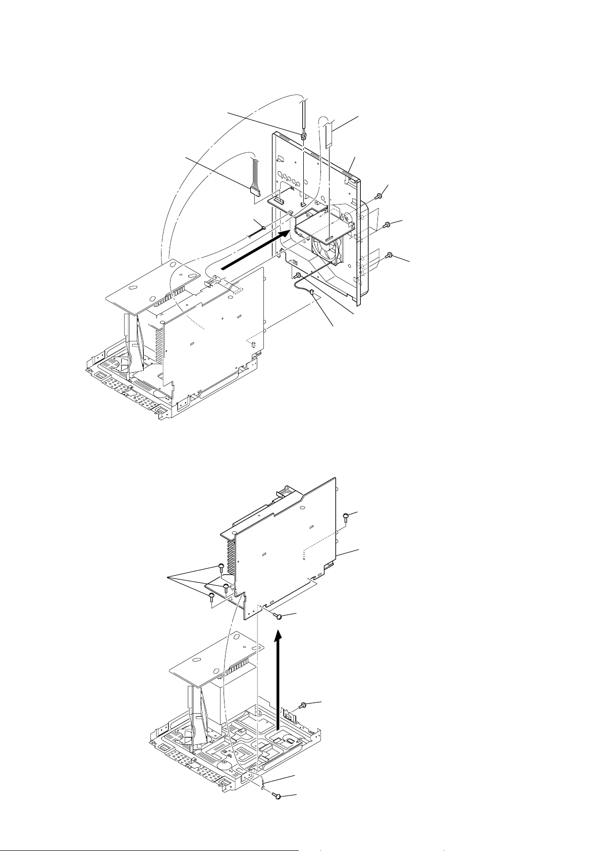
3-8. BACK PANEL BLOCK
2
connector
(CN1204)
2
connector
(CN1202)
2
connector
(CN1200)
1
wire (flat type) (19 core)
(CN1502)
6
back panel block
3
two
(BVTT 3
3
screws
×
three
(BVTT 3
10)
screws
×
10)
3-9. MAIN BOARD BLOCK
4
5
connector
(CN580)
3
screw
(BVTT 3
3
screw
(BV3 (3-CR))
6
MAIN board bloc
×
3
10)
four
screws
(BVTT 3
×
10)
12
3
three
(BV3 (3-CR))
screws
5
two
(BVTT 3
2
ground wire
1
screw
(BVTT 3
screws
×
4
screw
(BVTT 3
×
8)
×
10)
8)

3-10. MAIN BOARD
d
2
two
connectors
(CN513, CN514)
1
HCD-ZX80D/ZX100D
3
MAIN boar
screw
(BVTT 3
×
8)
3-11. COVER (CDM)
1
2
KARAOKE board
two
screws
(BVTT 3
×
10)
8
three
screws
(BVTT 3
7
connector
(CN201)
×
10)
2
two
connectors
(CN501, CN502)
6
wire (flat type) (24 core)
(CN101)
4
two
(BVTT 3
screws
×
10)
3
wire (flat type) (13 core)
(CN801)
5
VIDEO board
9
cover (CDM)
13

HCD-ZX80D/ZX100D
)
3-12. DRIVER BOARD, SW BOARD
1
two
(BTTP (M2.6))
4
DRIVER
2
wire (flat type) (5 core)
(CN702)
screws
board
3
connector
(CN703)
5
screw
(BTTP (M2.6))
6
SW board
3-13. OPTICAL PICK-UP BLOCK (KHM-310CAB or KHM-313CAB)
3
two
insulator
screws
4
two
insulators
7
optical pick-up block
(KHM-310CAB or
KHM-313CAB)
2
holder (310) assy
3
two
insulator
screws
5
connector
4
two insulators
6
wire (flat type
(24 core)
1
floating screw
(PTPWH M2.6)
14

3-14. SENSOR BOARD
2
t
ray
1
floating
(PTPWH M2.6)
6
floating
(PTPWH M2.6)
7
g
ear (geneva)
screw
8
s
(BTTP (M2.6))
screw
crew
0
SENSOR board
9
connector
(
CN731)
3
b
elt (table)
4
floating
(PTPWH M2.6)
5
p
HCD-ZX80D/ZX100D
screw
ulley (table)
3-15. MOTOR (TB) BOARD
2
stopper
4
1
stopper
7
t
able motor assy (M741)
3
wire (flat type) (5 core) (CN742)
8
MOTOR (TB) board
6
Remove the two solderings of motor.
5
two
screws
(BTTP (M2.6))
15

HCD-ZX80D/ZX100D
3-16. MOTOR (LD) BOARD
3
Remove the two solderings of motor.
5
l
oading motor assy (M751)
2
two
screws
(BTTP (M2.6))
4
MOTOR (LD) board
1
b
elt (loading)
16

SECTION 4
TEST MODE
HCD-ZX80D/ZX100D
PANEL TEST MODE
This mode is used to check the fluorescent indicator tube, LEDs,
keys, MASTER VOLUME knob, OPERATION DIAL knob, XROUND JOG knob, model, destination, software v ersion and VACS
level.
Procedure:
1. Press three buttons of x , [ENTER] and [DISC 2] simultaneously.
2. All LEDs except I/1 LED (green color) and segments in
fluorescent indicator tube are lighted up.
3. When you want to enter the software version display mode,
press the [DISC 1] button. The model information appears on
the fluorescent indicator tube.
4. Each time the [DISC 1] button is pressed, the display changes
from destination in fo rm ation, MC version, GC version, SYS
version, DVD version, ST version, TC version, TA version,
TM version in this order, and returns to the model information
display.
5. When the [DISC 3] button is pressed while the version numbers
are being displayed except model information and destination
information, the date of the software creation appears. When
the [DISC 3] button is pressed again, the display returns to the
software version display . When the [DISC 1] button is pressed
while the date of the software creation is being displayed, the
date of the software creation is displayed in the same order of
software version display.
6. Press the [DISC 2] button, the key check mode is activated.
7. In the key check mode, the fluorescent indicator tube displays
“K 0 V0J0 X0”. Each time a button is pressed, “K 0” value
increases. However, once a button has been pressed, it is no
longer taken into account.
8. “V” value increases in the manner of 0, 1, 2, 3 ... if the
[MASTER VOLUME] knob is turned clockwise, or it decreases
in the manner of 0, 9, 8, 7 ... if the [MASTER VOLUME] knob is
turned counterclockwise.
“J” value increases in the manner of 0, 1, 2, 3 ... if the
[OPERATION DIAL] knob is turned clockwise, or it decreases
in the manner of 0, 9, 8, 7 ... if the [OPERATION DIAL] knob is
turned counterclockwise.
“X” value increases in the manner of 0, 1, 2, 3 ... if the [X-
ROUND JOG] knob is turned clockwise, or it decreases in the
manner of 0, 9, 8, 7 ... if the [X-ROUND JOG] knob is turned
counterclockwise.
9. When the
(green color) and segments in fluorescent indicator tube light
up, the fluorescent indicator tube displays “VACS A+B F
APC”. A is conventional VACS level which is triggered by
signal level. B is thermal VACS level which is triggered by
temperature F is shown if the fan is turned in high speed and
vice-versa. C is VACS level which is triggered by APVACS
(Abuse Protection VACS). The signal le vel , which will trigger
VACS A is shown in the center area of the fluorescent
indicator tube.
10. When [EX-CHANGE/DISC SKIP] button is pressed after all LEDs
except I/1 LED (green color) and segments in fluorescent
indicator tube light up, alternate segments in fluorescent
indicator tube and LEDs would light up. If you press [EX-
CHANGE/DISC SKIP] button again, another half of alternate
segments in fluorescent indicator tube and LEDs would light
up. Press [EX-CHANGE/DISC SKIP] button again would cause
all LEDs except I/1 LED (green color) and segments in
fluorescent indicator tube lights up.
11. To release from this mode, press three buttons in the same
manner as step 1 or disconnect the power cord.
[DISC 3] button is pressed after all LEDs except I/1 LED
COMMON TEST MODE
This mode is used to check operations of the respective sections of
amplifier and tape.
Procedure:
• To enter common test mode
1. Press three buttons of x , [ENTER] and [DISC 3] simultaneously.
2. The DVD ring indicators, tape A and B indicators and the line
below DVD ring indicators and tape A and B indicators flash
synchronously on the fluorescent indicator tube. The function
is changed to “TV”.
• Check of amplifier
1. Press the [EQ BAND] button repeatedly until a message “GEQ
MAX” appears on the fluorescent indicator tube. GEQ
increases to its maximum.
2. Press the [EQ BAND] button repeatedly until a message “GEQ
MIN” appears on the fluorescent indicator tube. GEQ
decreases to its minimum.
3. Press the [EQ BAND] button repeatedly until a message “GEQ
FLAT” appears on the fluorescent indicator tube. GEQ is set
to flat.
4. When the [MASTER VOLUME] knob is turned clockwise even
slightly, the sound volume increases to its maximum and a
message “VOLUME MAX” appears on the fluorescent
indicator tube.
5. When the [MASTER VOLUME] knob is turned counterclockwise
even slightly, the sound volume decreases to its minimum and
a message “VOLUME MIN” appears on the fluorescent
indicator tube.
• Tape function
1. When a tape is inserted in deck-B and recording is started, the
function is changed to “TV” automatically. When the [CD
SYNC] button is pressed during recording in function, ALC
(Automatic Logic Control) is turned on.
2. During recording, press the
and the function is changed to “T APE B” and re wind the tape
in deck-B until the recording start position and playback of
the tape is started. If the [REC PAUSE/START] button is pressed
for a pause and pressed again to resume recording during
recording time, when the tape is rewind, the tape will be rewind
until the position where the pause is applied.
• To release common test mode
1. To release from this mode, press the I/1 button.
2. The cold reset is enforced at the same time.
m button will stop the recording
COLD RESET
The cold reset clears all data including preset data stored in the
RAM to initial conditions.
Procedure:
1. Press the I/1 button to turn on the system.
2. Press three buttons of x , [ENTER] and I/1 simultaneously.
3. The message “COLD RESET“ appears on the fluorescent
indicator tube. Then, the fluorescent indicator tube becomes
blink for a while , and the system is reset.
VACS ON/OFF
This mode is used to switch on and off the VACS (Variable
Attenuation Control System).
Procedure:
1. Press the I/1 button to turn on the system.
2. Press two buttons of x and [ILLUMINATION] simultaneously.
The message “VACS OFF” or “VACS ON” appears on the
fluorescent indicator tube.
17

HCD-ZX80D/ZX100D
TUNER STEP CHANGE
The step interval of AM channels can be toggled between 9 kHz
and 10 kHz. This mode is not available for Russian model.
Procedure:
1. Press the I/1 button to turn on the system.
2. Press the [TUNER/BAND] button repeatedly to select the “AM”.
3. Press the I/1 button to turn off the system.
4. Press two buttons of [ENTER] and I/1 simultaneously. The
system will turn on automatically. The message “AM 9k
STEP” or AM 10k STEP” appears on the fluorescent indicator
tube and thus the channel step is changed.
DVD SHIP MODE (WITH MEMORY CLEAR)
This mode moves the optical pick-up to the position durable to
vibration and clears all data including preset data stored in the RAM
to initial conditions. Use this mode when returning the set to the
customer after repair.
Procedure:
1. Press the I/1 button to turn on the system.
2. Press the [DVD] button to select the “DVD”.
3. Press three buttons of x , [DELAY] and I/1 simultaneously
during “DVD No Disc” condition. The system will turn off
automatically.
4. After the “STANDBY” blinking display finishes, a message
“MECHA LOCK” appears on the fluorescent indicator tube
and the DVD ship mode is set.
DVD SHIP MODE (WITHOUT MEMORY CLEAR)
This mode moves the optical pick-up to the position durable to
vibration.
Procedure:
1. Press the I/1 button to turn on the system.
2. Press the [DVD] button to select the “DVD”.
3. Press two buttons of [DVD]
“DVD No Disc” condition. The system will turn off
automatically.
4. After the “STANDBY” blinking display finishes, a message
“MECHA LOCK” appears on the fluorescent indicator tube
and the DVD ship mode is set.
and I/1 simultaneously during
DVD TRAY LOCK MODE
This mode is used to lock the disc tray. When this mode is acti vated,
the disc tray will not open when Z OPEN/CLOSE button or [EX-
CHANGE/DISC SKIP] button is pressed. The message “LOCKED”
appears on the fluorescent indicator tube.
Procedure:
1. Press the I/1 button to turn on the system.
2. Press the [DVD] button to select the “DVD”.
3. Press two buttons of x and Z OPEN/CLOSE simultaneously
and hold down until “LOCKED” or “UNLOCKED” appears
on the fluorescent indicator tube (around 5 seconds).
TV/SAT SWITCHING
This mode let you switch from TV to SAT and vice-versa.
Procedure:
1. Press the I/1 button to turn on the system.
2. Press the [TV/SAT] button to select the “TV”.
3. Press two buttons of [TV/SAT] and I/1 simultaneously. The
function will changed to SA T. Press the same buttons again to
change from SAT to TV.
DVD COLOR SYSTEM
This mode let you change the color system of the video output from
PAL to NTSC or vice-versa. This mode is not available for Latin
American model and Russian models.
Procedure:
1. Press the I/1 button to turn on the system.
2. Press the [DVD] button to select the “DVD”.
3. Press the I/1 button to turn off the system.
4. Press two buttons of X and I/1 simultaneously . The system
will turn on automatically. The message “COLOR PAL” or
“COLOR NTSC” appears on the fluorescent indicator tube.
REMOTE DISABLE MODE
This mode let you disable the remote commander reception. When
this mode is activated, the system will not response if the button on
the remote commander is pressed. The message “RemoteDisable”
appears on the fluorescent indicator tube. This mode is essential
for conducting test and repairing when no interruption from the
other remote commander is expected. This mode is cancelled
automatically when the AC power supply is cutoff.
Procedure:
1. Press the I/1 button to turn on the system.
2. Press three buttons of x , [FLANGER] and [DISC 2]
simultaneously until “RemoteDisable” or “RemoteEnable”
appears on the fluorescent indicator tube.
TCM OFFLINE MODE
This mode is used to prevent the system from turning off
automatically when TCM is not connected. Therefore, measurements
can be done even when TCM is not connected during production.
Procedure:
1. When the system is turned off, press three buttons of [EQ
BAND], [TAPE A/B] and
turn on automatically.
2. The message “TCM OFFLINE” appears on the fluorescent
indicator tube.
I/1 simultaneously. The system will
MTK FIRMWARE DISPLAY
This mode is used to display the MTK firmware version.
Procedure:
1. Press the I/1 button to turn on the system.
2. Press the [DVD] button to select the “DVD”.
3. Press the I/1 button to turn off the system.
4. Press two buttons of x and I/1 simultaneously. The system
will turn on automatically.
5. The version of MTK firmware appears on the TV screen.
MTK OFFLINE
This mode is used to enable audio output from the function other
than DVD function in order to check the audio output from the
system without connecting MTK.
Procedure:
1. Press the I/1 button to turn on the system.
2. Press three buttons of x , [FLANGER] and [DISC 1]
simultaneously and the message “MTK OFFLINE” appears
on the fluorescent indicator tube.
18

HCD-ZX80D/ZX100D
DVD SECTION
1. DVD SER VICE MODE GENERAL DESCRIPTION
This mode let you make diagnosis and adjustment easily by using
the remote commander and the TV screen. The instructions,
diagnostic results, etc. are given on the on-screen display.
2. ENTERING DVD SERVICE MODE
Procedure:
1. Press the I/1 button to turn on the system.
2. Press the [DVD] button to select the “DVD”.
3. Press two buttons x and Z OPEN/CLOSE simultaneously and
then turn the [MASTER VOLUME] knob clockwise.
4. The message “SERVICE IN” appears on the fluorescent
indicator tube and top menu of the Remocon Diagnosis Menu
appears on the on-screen display on the TV screen as follows.
The model name, IF-con version and Syscon version are
displayed at the bottom of the on-screen display.
Remocon Diagnosis Menu
0. External Chip Check
1. Servo Parameter Check
2. Drive Manual Operation
3. Emergency History
4. Version Information
Model Name :xxxxxxxxxx
IF-con:Ver.xx.xx(xxxx)
Syscon:Ver.x.xxx
Manual Adjust
1. Track Balance Adjust:
2. Track Gain Adjust:
3. Focus Balance Adjust:
4. Focus Gain Adjust:
5. Eq boost Adjust:
6. Iop:
7. TRV. Level:
8. S curve(FE) Level:
9. RFL(PI) Level:
0. MIRR Time:
V v Change Value
[RETURN]Return to previous menu
3. Select “6. Iop:” by pressing [6] button on the remote
commander.
4. Wait until a hexadecimal number appear in the on-screen
display as below.
Manual Adjust
1. Track Balance Adjust:
2. Track Gain Adjust:
3. Focus Balance Adjust:
4. Focus Gain Adjust:
5. Eq boost Adjust:
6. Iop: ED:
7. TRV. Level:
8. S curve(FE) Level:
9. RFL(PI) Level:
0. MIRR Time:
V v Change Value
[RETURN]Return to previous menu
5. To execute each function, press its number by using numeric
button on the remote commander.
6. To release from this mode, press the
system.
I/1 button to turn off the
3. EXECUTING IOP MEASUREMENT
In order to execute IOP measurement, the following standard
procedures must be followed.
Procedure:
1. From the top menu of Remocon Diagnosis Menu, select “2
Drive Manual Operation” by pressing the [2] button on the
remote commander. The following screen appears on the onscreen display
Drive Manual Operation
1. Servo Control
2. Track/Layer Jump
3. Manual Adjustment
4. Mecha Test Mode
5. MIRR time Adjust
0. Return to Top Menu
5. Convert data from hexadecimal to decimal by using conversion
table.
6. If the value is smaller than 93 (decimal), then it is OK. However
if the value is higher than 93, then BU (base unit) is defective
and need to be change.
7. Press the
return to previous menu.
8. Press the [0] button on the remote commander to return to the
top menu of Remocon Diagnosis Menu.
9. Press the I/1 button to turn off the system.
O RETURN button on the remote commander to
4. CHECKING EMERGENCY HISTORY
To check the emergency history, please follow the following
procedure.
Procedure:
1. From the top menu of Remocon Diagnosis Menu, select “3.
Emergency History” by pressing the [3] button on the remote
commander. The following screen appears on the on-screen
display.
Emg. History Check
Laser Hours CD 999h 59min
DVD 999h 59min
01. 01 05 04 04 00 92 46 00
00 00 00 00 00 00 23 45
2. Select “3. Manual Adjustment” by pressing the [3] button on
the remote commander. The following screen appears on the
on-screen display.
02. 02 02 01 01 00 A9 4B 00
00 00 00 00 00 00 23 45
[Next]Next page [Prev]Prev page
[0]Return to Top Menu
19

HCD-ZX80D/ZX100D
2. You can check the total time when the laser is turned on during
playback of DVD and CD from the above menu. The maximum
time, which can be displayed are 999h 59min.
3. You can check the error code of latest 10 emergency history
from the above menu. To view the previous or next page of
emergency history, press the . or > button on the
remote commander. The error code consists of three kinds of
error codes.
A. Error code
Example of Error code
01. 01 05 04 04 00 92 46 00
00 00 00 00 00 00 23 45
The meaning of error code is as below:
01: Communication error (No reply from syscon)
02: Syscon hung up
03: Power OFF request when syscon hung up
19: Thermal shutdown
24: MoveSledHome error
25: Mechanical move error (5 changer)
26: Mechanical move stack error
30: DC motor adjustment error
31: DPD offset adjustment error
32: TE balance adjustment error
33. TE sensor adjustment error
34. TE loop gain adjustment error
35. FE loop gain adjustment error
36. Bad jitter after adjustment
40. Focus NG
42. Focus layer jump NG
52. Open kick spindle error
51: Spindle stop error
60: Focus on error
61: Seek fail error
62: Read Q data/ID error
70: Lead in data read fail
71: TOC read time out (CD)
80: Can’t buffering
81: Unknown media type
B. Parameter of error code
This is the detail of error code.
Example of Error code
01. 01 05 04 04 00 92 46 00
00 00 00 00 00 00 23 45
To Clear the Laser Hour
Press the [ DISPLAY] button on the remote commander and then
press the [CLEAR] button on the remote commander. The data for
both CD and DVD data are reset.
Emg. History Check
Laser Hours CD 0h 0min
DVD 0h 0min
01. 01 05 04 04 00 92 46 00
00 00 00 00 00 00 23 45
02. 02 02 01 01 00 A9 4B 00
00 00 00 00 00 00 23 45
[Next]Next page [Prev]Prev page
[0]Return to Top Menu
To Clear the Emergency History
Press the [MENU] button on the remote commander and then press
the [CLEAR] button on the remote commander. The error code for
all emergency history would be reset.
Emg. History Check
Laser Hours CD 999h 59min
DVD 999h 59min
01. 00 00 00 00 00 00 00 00
00 00 00 00 00 00 00 00
02. 00 00 00 00 00 00 00 00
00 00 00 00 00 00 00 00
[Next]Next page [Prev]Prev page
[0]Return to Top Menu
To Return to the Top Menu of Remocon Diagnosis
Menu
Press the [0] button on the remote commander.
5. CHECKING VERSION INFORMATION
To check the version information, please follow the following
procedure.
Procedure:
1. From the top menu of Remocon Diagnosis Menu, select “4.
Ve rsion Information” by pressing the [4] button on the remote
commander. The following screen appears on the on-screen
display.
C. Time of error code
This is the laser time when an error occurred.
Example of Error code
01. 01 05 04 04 00 92 46 00
00 00 00 00 00 00 23 45
20
Version information
Firm(Main): Ver. X.XXXX
Firm(Sub): XX.XX
RISC: XXXXXX
8032: XXXXXX
Audio DSP: XX.XX.XX.XX
Servo DSP: XX.XX.XX.XX
[0]Return to Top Menu
2. To return to the top menu of Remocon Diagnosis Menu, press
the [0] on the remote commander.

SECTION 5
e
set
MAIN board
CN510
pin
1
(L-CH)
pin
3
(R-CH)
MAIN board
CN510
pin
2
(GND)
+
–
level meter
test tape
P-4-A100
(10 kHz, –10 dB)
MECHANICAL ADJUSTMENTS
HCD-ZX80D/ZX100D
SECTION 6
ELECTRICAL ADJUSTMENTS
PRECAUTION
1. Clean the following parts with a denatured-alcohol-moistened
swab :
record/playback head pinch roller
erase head rubber belts
capstan idlers
2. Demagnetize the record/playback head with a head
demagnetizer.
3. Do not use a magnetized screwdriver for the adjustments.
4. After the adjustments, appiy suitable locking compound to
the parts adjusted.
5. The adjustments should be performed with the rated power
supply voltage unless otherwise noted.
TORQUE MEASUREMENT
Mode Torque Meter Meter Reading
3.06 – 6.96 mN⋅m
FWD CQ-102C (31 – 71 g⋅cm)
(0.43 – 0.98 oz⋅inch)
FWD
Back Tension
REV CQ-102RC (31 – 71 g⋅cm)
REV
Back Tension
FF/REW CQ-201B (71 – 143 g⋅cm)
FWD CQ-403A more than 100 g
REV CQ-403R more than 100 g
CQ-102C (2.0 – 6.0 g⋅cm)
CQ-102RC (2.0 – 6.0 g⋅cm)
0.19 – 0.58 mN⋅m
(0.02 – 0.08 oz⋅inch)
3.06 – 6.96 mN⋅m
(0.43 – 0.98 oz⋅inch)
0.19 – 0.58 mN⋅m
(0.02 – 0.08 oz⋅inch)
6.96 – 14.02 mN⋅m
0.98 – 1.99 oz⋅inch)
9.80 mN⋅m
(more than 3.53 oz)
9.80 mN⋅m
(more than 3.53 oz)
0 dB=0.775 VDECK SECTION
1. Demagnetize the record/playback head with a head
demagnetizer.
2. Do not use a magnetized screwdriver for the adjustments.
3. After the adjustments, apply suitable locking compound to the
parts adjust.
TEST TAPE
Tape Signal Used for
P-4-A100 10 kHz, -10 dB Azimuth Adjustment
RECORD/PLA YBA CK HEAD AZIMUTH ADJUSTMENT
DECK A DECK B
Note : Perform this adjustment for both decks.
Procedure:
1. Mode: Playback
2. Turn the adjustment screw and check output peaks. If the peaks
do not match for L-CH and R-CH, turn the adjustment screw
so that outputs match within 1dB of peak.
Output
level
within
1dB
within
1dB
L-CH
peak
R-CH
Screw
position
peak
3. Mode: Playback
test tape
P-4-A100
(10 kHz, –10 dB)
L-CH
MAIN
board
CN510
R-CH
in phase 45°90°135°180
L-CH
peak
pin
L
R
pin
waveform of oscilloscope
good
1
pin
3
2
R-CH
peak
oscilloscop
wrong
Screw
position
H
V
°
21

HCD-ZX80D/ZX100D
e
V
4. After the adjustments, apply suitable locking compound to
the pats adjusted.
Adjustment Location: Playback Head (DECK-A)
Record/Playback/Erase Head (DECK-B)
reverse
forward
DVD SECTION
RFMON LEVEL CHECK
Connection :
oscilloscop
DMB15 board
CN105 pin
CN105 pin
Procedure :
1. Connect an oscilloscope to CN105 pin 6 (RFMON) and
CN105 pin 3 (GND) on the DMB15 board.
2. Press the I/1 button to turn the power on, and press
the Z OPEN/CLOSE button to open the CD disc table.
3. Set the test disc (DVD-SL (NTSC): HLX-503 (Part No. J6090-069-A, CD: YEDS-18 (Part No. 3-702-101-01) on the
tray and press the Y button to playback.
4. Confirm that oscilloscope waveform is clear and check
RFMON signal level is correct or not.
Note: A clear RFMON signal waveform means that the shape “◊” can be
clearly distinguished at the center of the waveform.
6
(RFMON)
3
(GND)
+
–
VOLT/DIV: 200 m
TIME/DIV: 500 ns
Connecting Location:
– DMB15 Board (Side A) –
CN105
16
IC201
IC102
level:
0.58
±
1.23 Vp-p
(DVD-SL)
0.57
±
1.1 Vp-p
(CD)
22

SECTION 7
DIAGRAMS
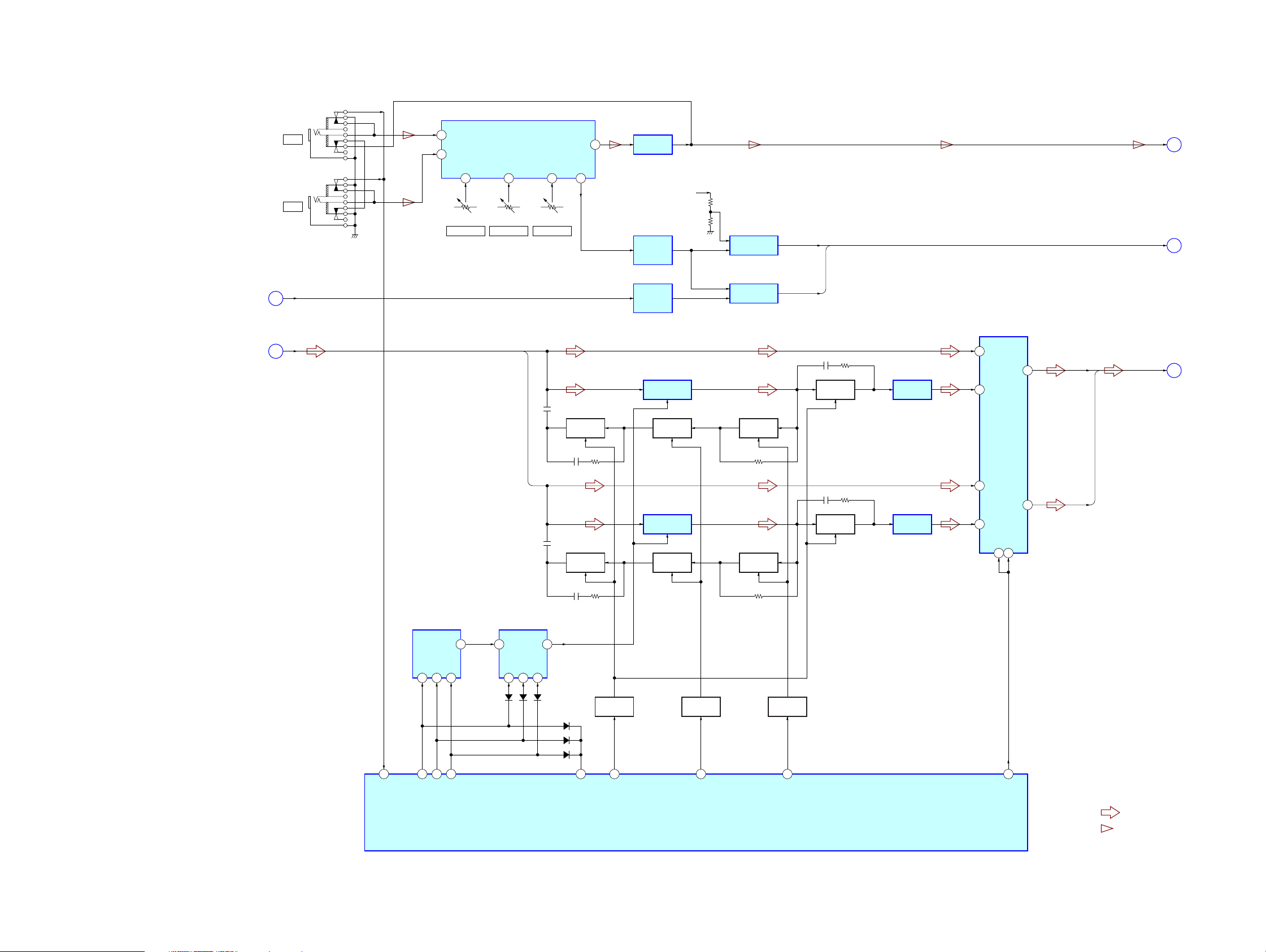
7-1. BLOCK DIAGRAM – RF SERVO/VIDEO SECTION –
HCD-ZX80D/ZX100D
VOD/D
OPTICAL PICK-UP
BLOCK
KHM-310CAB
OR
KHM-313CAB
VR (780)
VOA/A
VOB/B
VOC/C
MSW
ASDATA0 217 LOUT1+ 2
RF
PD
AUTOMATIC POWER
CONTROL (FOR CD)
Q102-1
AUTOMATIC POWER
CONTROL (FOR DVD)
Q102-2
CD ON
SWITCH
Q101-1
DVD ON
SWITCH
Q101-2
Q103
6
DVDRFIP
MA
8
MB
9
MC
10
MD
11
22LD (650)
50VR (650)
176LIMIT
ASDATA1 218 LOUT2+ 46
DVDA2
DVDB3
DVDC4
DVDD5
ASDATA2 219 LOUT3+ 42
TNI18VOE/E+G
TPI19VOF/F+H
V2O29VC
MDI120
ASDATA4 222 LOUT4+ 38
MDI221
LDO123LD (780)
LDO2
RF AMP, SERVO DSP,
MPEG DECODER
IC102
SPDATA 209
MSW
LIMSW
YUV3
YUV2
YUV1
ACLK
ABCK
6
5
EEPROM
SCL
SDA
198
196
194
ALRCK
IC103
SDTI114
SDTI215 SL
SDTI316 FC
SDTI413 LT
MCLK
10ACLK 215
BICK
9ABCK 214
LRCK
17ALRCK 213
8XRST 220
PDN
SDA
20SDA 103
19SCL 102
SCL
LOUT1– 1
ROUT1+
ROUT1–
D/A CONVERTER
IC301
LOUT2– 45
ROUT2+
LOUT3– 41
ROUT3+
LOUT4– 37
ROUT4+
SPDATA
MIX AMP
48
47
44
43ROUT2–
40
39ROUT3–
33
32ROUT4–
IC3711
MIX AMP
IC3731
MIX AMP
IC3751
MIX AMP
IC3771
FL
FR
SR
SW
RT
CENTER VOLTAGE
GENERATOR
Q3801
4
CVBSIN
2
CIN
6
YIN
AU+5V
VIDEO AMP, 75Ω DRIVER
IC801
CVBSOUT
S-DCOUT
C OUT
YOUT
J1102 (1/2)
VIDEO INPUT
VIDEO
23
26
27
21
SPDATA
ABCK
ABCK
ALRCK
VIDEO SWITCH, 75Ω DRIVER
IC800
3
VIN2
1
VIN1
7
VOUT
SW1
2
FL, FR, SL, SR, FC, SW
• R-ch is omitted due to same as L-ch.
• SIGNAL PATH
: CD PLAY
: DVD PLAY
: DIGITAL OUT
: AUDIO
: VIDEO
: Y
: CHROMA
: COMPONENT VIDEO
: VIDEO INPUT (VIDEO)
A/D CONVERTER
IC3601
12
DOUT
15
SCKI
11
BCK
10
LRCK
1
LIN
2
RIN
CY
R-CH
J802
VIDEO
OUT
J801
S VIDEO
OUT
LT, RT
ANALOG-L
B
(Page 26)
C
(Page 24)
D
(Page 26)
XVOICE, SCORE
A
(Page 24)
HCD-ZX80D/ZX100D
FCS+
FCS– 37
TRK+ 35
TRK– 34
SL+ 29
SL– 30
SP+ 27
SP– 28
REGO2
REGO1
FOCUS/TRACKING COIL DRIVE,
SPINDLE/SLED MOTOR DRIVE
IC201
36
46
47
42
31
32
FOCUS
COIL DRIVE
TRACKING
COIL DRIVE
SLED
MOTOR DRIVE
SPINDLE
MOTOR DRIVE
BUFFER
BUFFER
REGULATOR
MUTE5
200
YUV4
202
YUV5
1
4
10
13
45
19
21
20
22
40
8
FOO42
TRO41
FMO38
DMO37
SPFG47
MUTE123MUTE12 211
MUTEMUTE34 210
TSD_MTSD-M 170
IOPMON40
RF+3.3V
YUV6
203
2, 4, 5, 7, 8, 10, 11, 13, 42,
44, 45, 47, 48, 50, 51, 53
125 – 123, 121, 120, 118, 117,
115, 135, 133 – 128, 126
VOICE
SMSCK
206
208
XVOICE
SCORE
DQ0 – DQ15
RD0 – RD15
XTALI
229
X101
27MHz
228
XTALO
SD-RAM
IC104
A0 – A11
23 – 26,
29 – 34, 22, 35
147, 149 – 151, 166 – 164,
162, 160, 159, 146, 158
RA0 – RA11
AD0 – AD7
81 – 84,
86 – 88, 91
29, 31, 33, 35,
38, 40, 42, 44
DQ0 – DQ7
20
21
38
37
15
143
145
156
157
113
BA0 BA0
BA1 BA1
CKE CKE
RCLK CLK
DQM0 LDQM
IOA0 – IOA21
93, 78, 53 – 59, 75, 74,
72 – 67, 92, 60, 61, 76, 89
45, 25 – 18, 8 – 1,
48, 17, 16, 9, 10
A-1, A0 – A20
FLASH ROM
IC101
137
39
18
140
DQM1 UDQM
17
139
RAS /RAS
77
26
19
142
CAS /CAS
IOCSCE
79
28
RCS /CS
IOOEOE
16
138
RWE /WE
IOWRWE
66
11
10
CYIN
12
CBIN
14
CRIN
S1
25
49
WIDE
98
100
205
24
105
23
MTK-XIFCS IXFCS
MTK-IFBSY IFBSY
207
110
21
22
25
MTK-KMOD KRMOD
MTK-RESET PRST
MIC STATUS MIC
101
99
32
31
33
MTK-SIO IFSDI
MTK-CLK IFCK
MTK-SOD IFSDO
CYOUT
CBOUT
CROUT
MUTE113MUTE2
3
88
VMUTE
20
18
16
MASTER CONTROLLER
IC401 (1/6)
87
LM-F
LM-R
VIDEO-OUT-SW
TM-F
TM-R
TBL SENS
E1
E2
E3
EJECT SW
LOADING MOTOR DRIVE
7
38
9
39
7
36
9
37
27
35
34
28
26
IC701
FIN
OUT1
OUT2
FIN
TABLE MOTOR DRIVE
IC712
FIN
OUT1
OUT2
FIN
LEVEL SHIFT
Q731
S711
ROTARY
ENCODER
S751
DISC TABLE
OPEN/CLOSE DETECT
OPEN
CLOSE
Y
PB/C
PR/C
4
M
2
4
M
2
DISC TABLE
ADDRESS SENSOR
IC731
DISC TABLE
DETECT
ADDRESS
COMPONENT
B
R
M751
(LOADING)
M741
(TABLE)
J800
VIDEO OUT
2323
HCD-ZX80D/ZX100D
7-2. BLOCK DIAGRAM – MIC/EFFECTOR SECTION –
(Page 26)
(Page 23)
E
C
J1100
MIC 1
J1101
MIC 2
MUSIC L+R
LT, RT
16
MC2P
15
MC1P
MIC 1 LEVEL
VOL2
6
RV1102
DIGITAL ECHO
IC1100
VOL1
5
RV1101
MIC 2 LEVEL
VOL321MCO
7
RV1100
ECHO LEVEL
LT
POOUT
SWITCHING
Q1505
29
MIC AMP
IC1101
MIC
F
(Page 26)
A+9V
AC/DC
CONVERTER
IC2000 (1/2)
AC/DC
CONVERTER
IC2000 (2/2)
DIGITAL ECHO
IC1504
SWITCHING
Q1504
COMPARATOR
IC2002
COMPARATOR
IC2001
SWITCHING
Q1503
XVOICE
SCORE
SWITCHING
Q1508
MIXER
IC1505 (2/2)
SIGNAL SELECTOR
IC1506
1
0Y
Y COM
4
3Y
3
DM_L
XVOICE, SCORE
DM_L, DM_R
A
(Page 23)
G
(Page 26)
85
MIC-DETECT
MULTIPLEXER
IC1503
COM
A10B9C
11
19
43
EFFECTOR-S0
EFFECTOR-S1
3
44
EFFECTOR-S2
MULTIPLEXER
IC1502
13
D0
A10B9C
11
D1503
COM
D1504
RT
D1505
3
D1506
D1507
D1508
SWITCHING
Q1502
45
EFFECTOR-S3
LEVEL SHIFT
Q1509, 1510
57
EFFECTOR-CTR1
DIGITAL ECHO
IC1501
SWITCHING
Q1501
LEVEL SHIFT
Q1511, 1512
63
EFFECTOR-CTR2
SWITCHING
Q1500
LEVEL SHIFT
Q1513, 1514
70
EFFECTOR-CTR3
SWITCHING
Q1506
MIXER
IC1505 (1/2)
MASTER CONTROLLER
IC401 (2/6)
12
0X
13
X COM
11
3X
B
9A10
18
DM_R
• SIGNAL PATH
: AUDIO
EFFECTOR-SELECT
: MIC INPUT
HCD-ZX80D/ZX100D
2424

7-3. BLOCK DIAGRAM – TUNER/TAPE SECTION –
HCD-ZX80D/ZX100D
HP1
(PB)
(DECK-A)
HRPE1
(REC/PB/ERASE)
(DECK-B)
L-CH
R-CH
L-CH
R-CH
R-CH
R-CH
MUTING
Q325
MUTING
Q321, 322
R-CH
R-CH
MUTING CONTROL
SWITCH
Q382, 383
MUTING CONTROL
SWITCH
Q377, 379, 381
ANTENNA
FM 75Ω
COAXIAL
AM
DECK A/B SELECT SWITCH,
REC/PB EQ AMP
IC301
AIN1
32
BIN1
34
REC-OUT1 REC-IN1
21 24
EQ-OUT1
MUTE ON/OFF
A/B
ALC ON/OFF
REC MUTE ON/OFF
EQ
TUNER (FM/AM)
FM ANT
AM ANT
ST-DOUT/MC-DIN
ST-DIN/MC-DOUT
28
14
13
11
15
TAI1 PB-OUT1
27 26
ST-L
ST-R
ST-CLK
ST-CE
TUNED
R-CH
MUTING
Q106
R-CH
MUTING CONTROL
SWITCH
Q509, 510
5
2
3
6
1
71
55
56
54
53
ST-DIN
ST-DOUT
ST-CLK
ST-CE
TUNED
TC-MUTE
PB A/B
ALC
REC MUTE
TC-RELAY
ST-L
TC-L
REC-L
H
J
K
(Page 26)
(Page 26)
(Page 26)
ERASE
• R-ch is omitted due to same as L-ch.
• SIGNAL PATH
: TUNER (FM/AM)
: TAPE PLAY (DECK-A)
: TAPE PLAY (DECK-B)
: REC
T301
BIAS OSC
BIAS OSC
Q370
REC BIAS
SWITCH
Q378, 380
A+9V
TAPE MECHANISM
DECK BLOCK
A SHUT
B SHUT
AHALF
BHALF
REC (FWD)
REC (REV)
ATRGM+
(DECK-A)
BTRGM+
(DECK-B)
CAPM+
M
(CAPSTAN/REEL)
TRIGGER PLUNGER
DRIVE (DECK-A)
Q340, 343
TRIGGER PLUNGER
DRIVE (DECK-B)
Q342, 345
CAPSTAN/REEL
MOTOR DRIVE
Q341, 344
MASTER CONTROLLER
IC401 (3/6)
REC BIAS
52
A-SHUT
89
B-SHUT
90
A-HALF
47
B-HALF
91
A-TRIG
48
B-TRIG
49
CAPM
50
HCD-ZX80D/ZX100D
2525
HCD-ZX80D/ZX100D
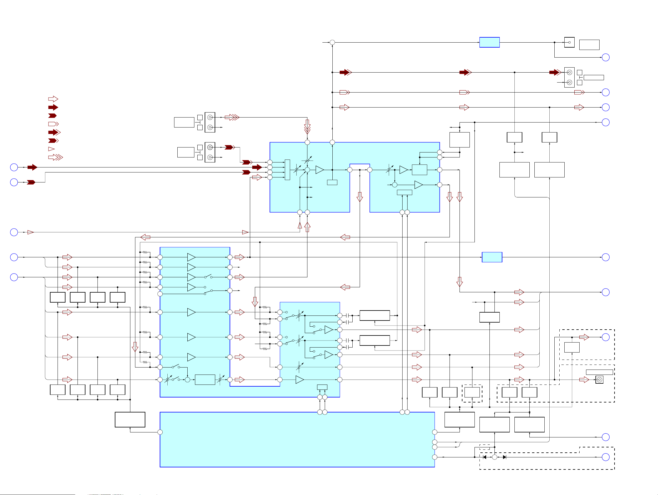
7-4. BLOCK DIAGRAM – AUDIO SECTION –
• R-ch is omitted due to same as L-ch.
• SIGNAL PATH
: AUDIO
: TUNER (FM/AM)
: TAPE PLAY
: REC
: AUDIO OUT
: TV/SAT AUDIO IN
: MIC INPUT
(Page 25)
ST-L
H
TC-L
J
(Page 25)
: VIDEO INPUT (AUDIO)
VIDEO INPUT
AUDIO
TV/SAT
AUDIO IN
J1102 (2/2)
L
R
J201
L
R
R-CH
R-CH
R-CH
+
SPEANA AMP
IC304 (2/2)
J202
R-CH
D-LIGHT
SYNC OUT
L
R
J103
SPEANA
AUDIO OUT
REC-L
L
(Page 28)
K
(Page 26)
ANALOG-L
D
(Page 23)
DBFB F/B
M
(Page 27)
BB_A1
BB_B1
OUT1
SWOUT
R-CH
FEED BACK
SWITCH
Q101
16
17
24
MUTING
Q206
MUTING CONTROL
SWITCH
Q521, 522
OUT-MUTE
R-CH
MUTING
Q117
MUTING CONTROL
SWITCH
Q516, 517
IN-MUTE
INPUT SELECT SWITCH,TONE CONTROL,
ELECTRICAL VOLUME, BASS BOOST AMP
7
SELECTOR
MIC
2 42
VIDEO-L
+
SUR1
SAT-L
4
ST-L
6
TC-L
3
DVD-L
5
R-CH
R-CH
RECB1
TONE
8
TOUT1
14 15 18
VOLIN1
R-CH
+
IC101
I/F MCU
DATA
2221
CLOCK
BASS
BOOST
MIC
F
(Page 24)
DM_L, DM_R
G
(Page 24)
FL, FR, SL,
SR, FC, SW
B
(Page 23)
DM_L
DM_R
FL
FR
MUTING
SL
SR
FC
SW
MUTING
Q204
Q202
MUTING
Q254
MUTING
Q252
MUTING
Q203
MUTING
Q200
MUTING
Q253
MUTING
Q250
MUTING CONTROL
SWITCH
Q507, 508
37
40
41
2
33
6
10 9 8
13
15
AUTO GAIN
+
CONTROL
77
DVD-A-MUTE
38
39
R-CH
34
32
R-CH
5
R-CH
12
ELECTRICAL VOLUME
IC201
4
3
7
11
2314 24 22
I/F
17
18
81
82
VOL-IC-CLK
VOL-IC-DATA
MASTER CONTROLLER
IC401 (4/6)
BUFFER
IC304 (1/2)
MUSIC L+R
E
(Page 24)
FL
R-CH
31
30
29
28
27
26
25
FEED BACK SWITCH
Q205
FEED BACK SWITCH
Q255
79
80
LINE-MUTE
AUDIO-IC-CLK
AUDIO-IC-DATA
AUDIO-OUT-SW
ANALOG-IN-MUTE
SW-MUTE
MUTING
Q750
76
83
46
75
MUTING
Q700
MUTING CONTROL
SWITCH
Q505, 506
OUT-MUTE
IN-MUTE
(ZX100D)
MUTING
Q740
(ZX100D)
MUTING
Q514, 564
MUTING CONTROL
SWITCH
Q511
+
D511D510
MUTING
Q207
MUTING CONTROL
FR
SL
SR
CTR
MUTING
Q208
SWITCH
Q512, 515, 519
FL, FR, SL, SR, CTR
MUTING
Q810
(Page 27)
SW
(Page 27)
(ZX100D)
J203
SUBWOFFER OUT
(ZX80D)
(Page 28)
AC4
(ZX80D)
SW-MUTE
(Page 27)
N
P
Q
S
HCD-ZX80D/ZX100D
2626
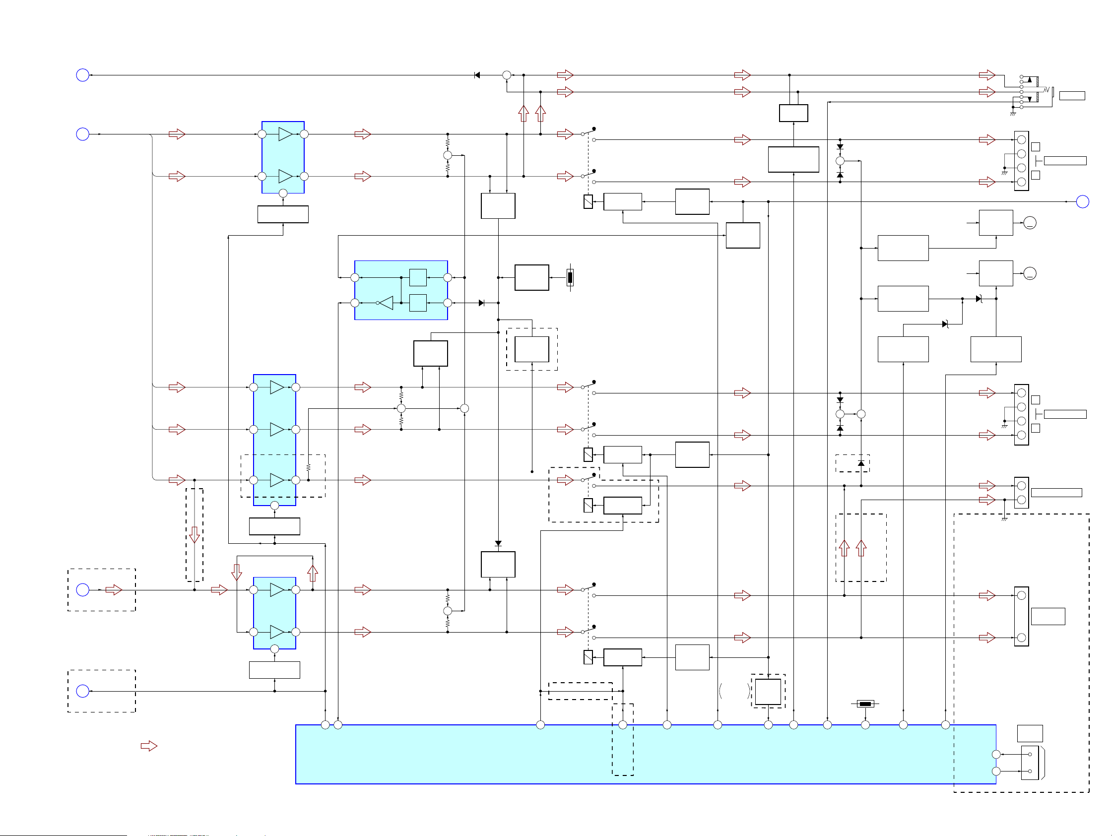
7-5. BLOCK DIAGRAM – AMP SECTION –
HCD-ZX80D/ZX100D
M
(Page 26)
N
(Page 26)
(ZX100D)
P
(Page 26)
(ZX80D)
S
(Page 26)
DBFB F/B
FL, FR, SL, SR, CTR
SW
SW-MUTE
FL
FR
SL
SR
CTR
(ZX80D)
• SIGNAL PATH
: AUDIO
POWER AMP
IC600
18 11
14 8
12
STANDBY SWITCH
Q604, 606, 610
POWER AMP
IC702
18 11
14 8
19 21
12
STANDBY SWITCH
Q720 – 722
POWER AMP
IC800
11 4
15 6
13
STANDBY SWITCH
Q812
(ZX100D)
60
STK-MUTE
OVER CURRENT PROTECTOR
CT
4
OUT OCP
3
67
PROTECT
IC550
DC
DET
OVER
LOAD
OVER LOAD
DETECT
Q730, 780
+
MASTER CONTROLLER
VP
IC401 (5/6)
D624
+
J1103
PHONES
MUTING
Q640, 641
SWITCH
Q588
SWITCH
Q585
Q578
TM600
+
–
–
+
M
M
TM700
+
–
–
+
TM701
+
–
TM101
L
FRONT SPEAKER
R
AC CUT DETECT
(Page 28)
M502
(FAN)
M501
(FAN)
L
SURR SPEAKER
R
CENTER SPEAKER
R
–1
+
–2
OVER LOAD
DETECT
Q618, 668
2
1
D550
THERMAL
DETECT
Q628, 630
(ZX100D)
OVER LOAD
DETECT
Q770
RY646
TH629
RELAY DRIVE
Q644
–1
PROTECT
SWITCH
Q647
OVER LOAD
DETECT
Q648
MUTING CONTROL
SWITCH
Q634, 682
+
–2
PROTECT
SWITCH
Q765
D812
OVER LOAD
DETECT
Q800, 850
(ZX100D)
RY760
RY761
RELAY DRIVE
Q763
RELAY DRIVE
Q762
–1
D655
+
D654
D764
+ +
D763
(ZX100D)
D765
CONTROL SWITCH
CONTROL SWITCH
FAN MOTOR SPEED
CONTROL SWITCH
(ZX80D)
FAN MOTOR
Q587, 589
FAN MOTOR
Q581, 582
Q579
D581
UNREG
B+
UNREG
B+
FAN MOTOR
FAN MOTOR
D582
FAN MOTOR
CONTROL SWITCH
+
+
–2
SUBWOOFER
OUT
–
PROTECT
SWITCH
61
REAR-RELAY
Q815
Mexican
66
FR-RELAY
Except
AC CUT
DETECT
Q504
69
UNDER VOLTAGE
72
HP-MUTE
84
HP-DETECT
TH630
94
THERMAL VACS
58
FAN HI SPEED
42
SW-LEVEL-IN
FAN CONTROL
SW-LED
CN102
SYSTEM
CONTROL
95
100
TO
SS-WGV100D
(ZX100D)
65
CTR-RELAY
RY862
(ZX80D)
RELAY DRIVE
Q814
51
SW-SPK RELAY
(ZX100D)
HCD-ZX80D/ZX100D
2727

HCD-ZX80D/ZX100D
7-6. BLOCK DIAGRAM – PANEL/POWER SUPPLY SECTION –
SPEANA
L
(Page 26)
FL901
FLUORESCENT
INDICATOR TUBE
S900 – 925,
S1041 – 1047, 1049
(FRONT & TOP PANEL KEY)
OPERATION DIAL
MASTER VOLUME
X-ROUND JOG
GRID DRIVE
Q901, 902, 914
ROTARY
ENCODER
S1161
ROTARY
ENCODER
S970
ROTARY
ENCODER
S1040
1
IN1
2
IN2
9, 10, 12– 22,
93 – 95
8 – 1, 100 – 96,
64 – 66
72
74
73
3BUF1OUT
20BUF2OUT
BAND-PASS FILTER
P1 – P36
24 – 41, 43 – 47
G14 – G16
92 – 85
G1 – G13,
G17 – G24
KEY 0 – KEY 2
OPERATION DIAL
LED- (BALANCE, WAVE, FADER, RANDOM), DELAY,
VOLUME
X-JOG-ROUND
4
5
6
7
8
9
19
18
IC904
DISPLAY CONTROLLER
IC902
LED-VIDEO, (PAUSE, STOP),
LED- (AMS+, AMS–), (FF, FR),
LED- (BEAT JUMP, BEAT MAX),
LED-FLANGER, CHORUS,
XIN82XOUT
83
X901
4MHz
BPF2IN1
BPF2IN2
BPF3IN1
BPF3IN2
BPF4IN1
BPF4IN2
BPF1IN1
BPF1IN2
LED-CD/DVD, TUNER,
LED-TAPE, TV/SAT,
LED-VOLUME 1, 2,
LED-VOLUME 3, 4,
LED-VOLUME 5, 6,
LED-VOLUME 7, 8,
LED-PLAY
I2C-CLOCK
15BPF3OUT
14BPF2OUT
13BPF1OUT
16BPF4OUT
17RECOUT
71BF1
70BF2
69BF3
68BF4
67ALL-BAND
80LED SELECTOR
52 – 59, 75, 76, 78, 79
REMOTE CONTROL
BPF3
BPF2
BPF1
BPF4
REC
BPF1
BPF2
BPF3
BPF4
REC
LED ON/OFF
CONTROL SWITCH
Q906
LED DRIVE
Q908 – 913, 915,
918 – 921, 1041
RECEIVER
IC903
S927
I
S928
DISPLAY
/ 1
SEL B B+ LED+9V
SEL A B+
LED ON/OFF
CONTROL SWITCH
Q907
D908 – 911, 913 – 917,
D919 – 926, 929, 930,
D1016, 1017, 1020, 1040,
D1042, 1044, 1046, 1048,
D1050, 1052, 1054, 1056,
MASTER CONTROLLER
IC401 (6/6)
3060 IIC-DATAI2C-DATA
2961 IIC-CLK
4077 GC-RESETRESET
4
SIRCS
74 POWER-KEY
73 DISPLAY-KEY
X-IN13X-OUT
15
B+ SWITCH
Q905
B+ SWITCH
Q904
D1058, 1145, 1153
MTK- POWER
OVER VOLTAGE
STBY-RELAY
STBY-LED
AC-CUT
RESET
XC-IN11XC-OUT
10
D661
T1200
POWER
D660
+VL
–VL
+3.3V
SW+5V
+5.6V
REGULATOR
Q1507
+4V
REGULATOR
Q323
+5V
REGULATOR
Q103
REGULATOR
REGULATOR
REGULATOR
+3.3V
IC105
+3.3V
IC107
+1.8V
IC106
D101, 102
D585, 586
TO FLUORESCENT
INDICATOR TUBE
REGULATOR
REGULATOR
REGULATOR
+5V
REGULATOR
IC558
+3.3V
REGULATOR
IC559
+9V
IC560
+9V
IC561
+9V
IC507
FL901
EVER+3.3V
+VH
–VH
VP
(–36V)
VF1
VF2
OVER VOLTAGE
DETECT
(Except Mexican)
B+ SWITCH
Q513, 520
EVER+4V
D+3.3V
Q550
+5.6V
D+4V
AU+5V
RGRULATOR
CONTROL SWITCH
Q104
A+9V
M+9V,
LED+9V
SW+9V
RGRULATOR
CONTROL SWITCH
Q503, 518
RF+3.3V
RF+1.8V
SW+3.3V
78
68
7
41
20
12
LED DRIVE
Q903
LED DRIVE
Q917
RESET
SWITCH
Q501
D927
I
/ 1
(RED)
D928
I
/ 1
(GRN)
RESET SIGNAL
GENERATOR
IC501
UNREG B+
D551
RECT
D561
B+ SWITCH
Q523, 524
M+9V
RECT
D658
RECT
D656
–36V
REGULATOR
Q1264
RECT
D560
D505
D504
F1261
F1271
F1241
F1251
D1292
F1281
F1291
D507
D506
TRANSFORMER
AC2
AC2
AC1
AC1
VP
VF
VF
AC3
AC3
AC4
AC4
POWER
SWITCHING
(Except Mexican)
VOLTAGE
SELECTOR
S1200
(Mexican)
POWER ON/OFF
RELAY DRIVE
Q1200
RY1200
AC CUT DETECT
(Page 27)
(AC IN)
AC4
(Page 26)
R
Q
HCD-ZX80D/ZX100D
X402
5MHz
X401
32.768kHz
2828

HCD-ZX80D/ZX100D
)
d
• Note for Printed Wiring Boards and Schematic Diagrams
Note on Printed Wiring Board:
• X : parts extracted from the component side.
• Y : parts extracted from the conductor side.
f
•
• : Pattern from the side which enables seeing.
(The other layers' patterns are not indicated.)
Caution:
Pattern face side: Parts on the pattern face side seen from
(Side B) the pattern face are indicated.
Parts face side: P arts on the parts face side seen from
(Side A) the parts face are indicated.
• DMB15 board is multi-layer printed board.
• Indication of transistor
: internal component.
However, the patterns of intermediate layers have not been
included in diagrams.
C
Q
B
E
Q
B
These are omitted.
CE
These are omitted.
Note on Schematic Diagram:
• All capacitors are in µF unless otherwise noted. (p: pF)
50 WV or less are not indicated except for electrolytics
and tantalums.
• All resistors are in Ω and 1/
specified.
f : internal component.
•
• 2 : nonflammable resistor.
• 5 : fusible resistor.
• C : panel designation.
Note: The components identified by mark 0 or dotted line
with mark 0 are critical for safety.
Replace only with part number specified.
• A : B+ Line.
• B : B– Line.
• Voltages and waveforms are dc with respect to ground
under no-signal (detuned) conditions.
– DMB15/VIDEO Boards –
no mark : DVD PLAY
∗ : Impossible to measure
– Other Boards –
no mark : TUNER (FM/AM)
(): DVD PLAY
〈〈 〉〉 : TAPE PLAY (DECK-A)
{ }: REC
∗ : Impossible to measure
• Voltages are taken with a VOM (Input impedance 10 MΩ).
Voltage variations may be noted due to normal production tolerances.
• Waveforms are taken with a oscilloscope.
Voltage variations may be noted due to normal production tolerances.
• Circled numbers refer to waveforms.
• Signal path.
J : CD PLAY
c : DVD PLAY
I : DIGITAL OUT
F : AUDIO
L : VIDEO
E : Y
a : CHROMA
r : COMPONENT VIDEO
f : TUNER (FM/AM)
j : TAPE PLAY (DECK-A)
d : TAPE PLAY (DECK-B)
G : REC
k : TV/SAT AUDIO IN
h : AUDIO OUT
N : MIC INPUT
g : VIDEO INPUT (AUDIO)
p : VIDEO INPUT (VIDEO)
• Abbreviation
E2 : 120V AC area in E model
E3 : 240V AC area in E model
E13 : Russian model and 220V – 230V AC area in E
E51 : Chilean and Peruvian models
MX : Mexican model
MY : Malaysia model
SP : Singapore model
model
4
W or less unless otherwise
• Circuit Boards Location
TRANS board
SURROUND board
MOTOR (LD) board
CD-SW board
JOG board
PRIMARY board
X-ROUND board
PA board
SW board
POWER SWITCHING
EFFECTOR boar
MAIN board
VIDEO board
SENSOR board
DMB15 board
MOTOR (TB) board
TUNER (FM/AM
KARAOKE board
DRIVER board
PANEL board
HCD-ZX80D/ZX100D
FUNCTION board
MIC board
2929

HCD-ZX80D/ZX100D
• Semiconductor
Location
Ref. No. Location
D1001 E-3
D3501 H-5
D3502 H-5
IC101 C-7
IC102 E-6
IC103 E-4
IC104 E-4
IC106 E-3
IC201 C-4
Q103 F-8
Q3801 G-5
7-7. PRINTED WIRING BOARD – DMB15 Board (Side A) –
1 2 3 4 5 6 7 8 9
A
DMB15 BOARD
(SIDE A)
(FOR CHECK)
CN105
B
R208
R209
C205
R214
R215
C206
C
R210
C208
FL402
R3737
R3717
R3716
R3731
R3733
R3738
R3718
C403
R3732
C3731
C3732
R216
C402
5
1
R3734
R3714
21
C189
R3736
R3742
C3733
C3703
C3734
R3722
C3713
C3714
20
C3701
C210
FB406
R3653
C305
R3741
R3721
D1001
R1527
R3735
R3746
C3744
R3715
R3726
C3724
R224
R219
FB404
C187
C3741
C3721
C306
R3743
R3744
C3742
R3745
C3743
R3747
R3748
R3723
R3724
C3722
R3725
C3723
R3727
R3728
FB405
FB401
FB403
FB402
FL403
FL401
D
B
MAIN BOARD
NO523
CN401
(Page 45)
IC106
E
C307
F
G
H
R3801
R319
R3603
R3802
C3801
R3607
C3603
C3608
L3602
C3605
R3651
C3606
R3712
C3711
R3711
R3713
C3609
C3712
• See page 29 for Circuit Boards Location.
R107
R233
C215
C220
C224
C218
C219
IC201
C217
C221
C222
RB107
RB108
C190
C179
C180
IC104
C181
CN302
R191
R193
C167
IC103
C302
C177
C178
FL107
C3804
R3803
R3804
Q3801
E
C3802
C3803
1
2
C170
R1101
C3805
R3805
D3501
R1105
D3502
R1108
R1553
R189
R3757
R3758
R3751
3753
R
R3777
R3778
190
R
R3771
R3773
R3752
C3751
C3752
192
R
C3771
C3772
RB113
R195
R3754
R3756
C3754
3774
R
C3774
R3762
R3755
C3753
C3705
R3772
R3775
C3773
R3776
RB112
R197
R3761
R3782
C3707
R161
1102
R1550
R
R3781
R1549
R155
3766
R
3786
R
: Uses unleaded solder.
(Page 45)
MAIN BOARD
A
CN520
CN106
FB114
FB113
FB112
FB115
C102
R1557
R152
IC101
IC102
R1168
R142
X101
C153
R1543
C3762
R3764
R3765
C3763
R3767
R3768
C3764
R3784
R3787
R3788
C3784
C3761
C3781
C3782
R3785
C3783
R153
R3763
R3783
C108
C152
R1559
R1544
C138
C132
C133
C129
C137
C135
R4706
C150
R234
R136
C116
C117
R4705
C119
CN301
C118
R117
C105
C112
FL101
R116
E
Q103
R101
C101
CN201
CN101
R1129
OPTICAL
PICK-UP
BLOCK
KHM-310CAB
OR
KHM-313CAB
New part of EEPROM (IC103) on the DMB15 board cannot be used.
Therefore, if the mounted DMB15 board is replaced, exchange new
EEPROM with that used before the replacement.
HCD-ZX80D/ZX100D
D
3030
MAIN BOARD
CN521
(Page 45)
C
VIDEO BOARD
CN801
1-869-463-
(Page 38)
11
 Loading...