

Page 1
– 1 –
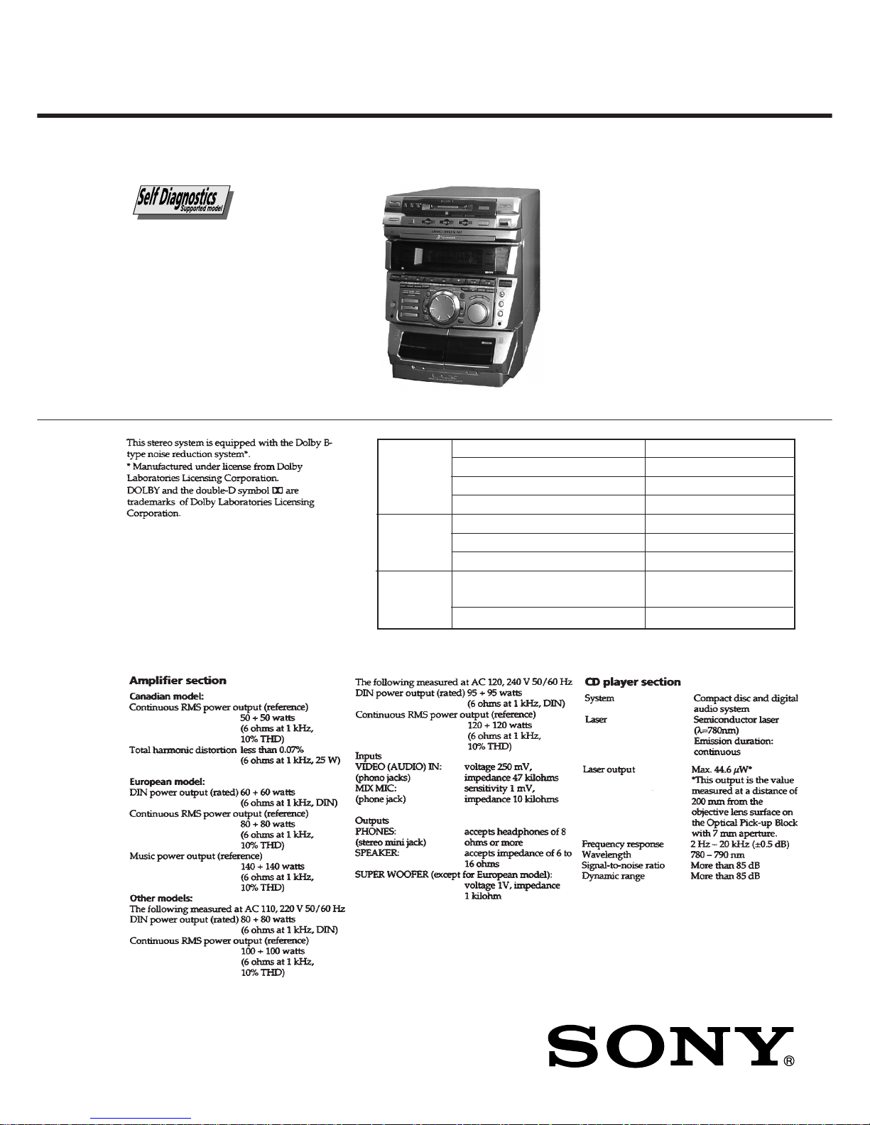
HCD-MDX10
US Model
Canadian Model
AEP Model
UK Model
E Model
Australian Model
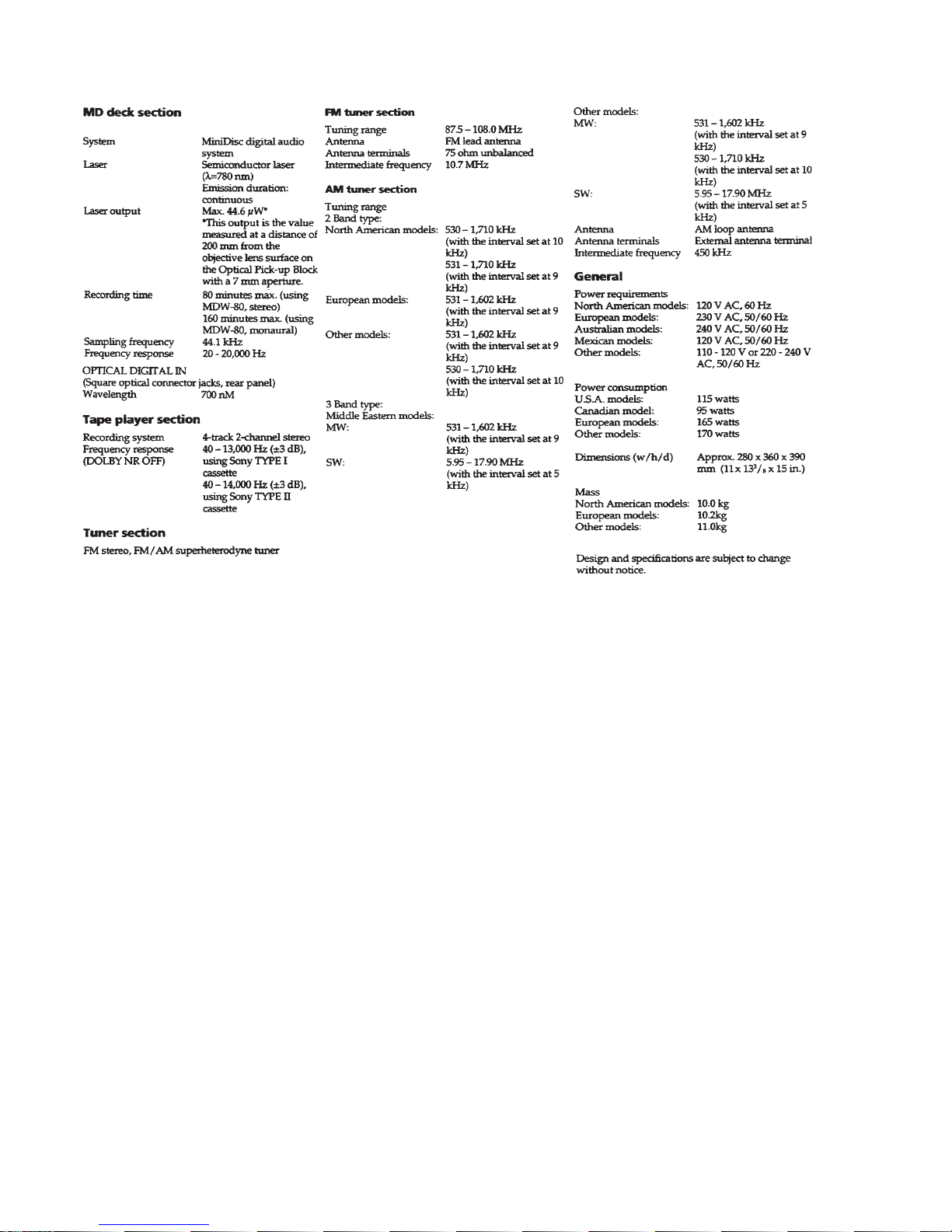
SPECIFICATIONS
COMP ACT DISC DECK RECEIVER
— Continued on next page —
Model Name Using Similar Mechanism NEW
Mechanism Type CDM38LH-5BD32L
Base Unit Type BU-5BD32L
Optical Pick-up Type KSS-213D/Q-NP
Model Name Using Similar Mechanism MDS-JE520
Mechanism Type MDM-5A
Optical Pick-up Type KMS-260A/K1NP
Model Name Using Similar Mechanism HCD-DR4/DR5/DR6/DR440/
W300/W5000/XB500
Tape Transport Mechanism Type TCM-230AWR2/230PWR2
CD
SECTION
TAPE DECK
SECTION
SERVICE MANUAL
HCD-MDX10 is the tuner, deck,
CD, MD and amplifier section in
MHC-MDX10.
MD
SECTION
Ver 1.1 2001. 06
9-928-878-12
2001F0200-1
© 2001.6
Sony Corporation
Home Audio Company
Shinagawa Tec Service Manual Production Group
Page 2
– 2 –
Page 3
– 3 –
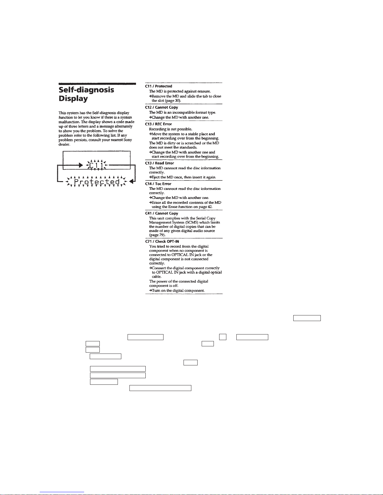
SELF-DIAGNOSIS FUNCTION
The self-diagnosis function consists of error codes for customers which are displayed automatically when errors occur, and error codes which
show the error history in the test mode during servicing. For details on how to view error codes for the customer, refer to the following box
in the instruction manual. For details on how to check error codes during servicing, refer to the following “Procedure for using the SelfDiagnosis Function (Error History Display Mode)”.
Procedure for using the Self-Diagnosis Function (Error History Display Mode).
Note: Perform the self-diagnosis function in the “error history display mode” in the test mode. The following describes the least required
procedure. Be careful not to enter other modes by mistake. If you set other modes accidentally, press the MENU/NO button to exit
the mode.
1. With the power ON, press the CD-MD SYNC button while pressing the p and ENTER/YES buttons together.
2. Rotate the AMS dial and when “Service” is displayed, press the YES button.
3. Rotate the AMS dial and display “ERR DP MODE”.
4. Pressing the ENTER/YES button sets the error history mode and displays “total rec”.
5. Select the contents to be displayed or executed using the AMS dial.
6. Pressing the MD WALKMAN SYNC button will display or execute the contents selected.
7. Pressing the MD WALKMAN SYNC button another time returns to step 4.
8. Pressing the MENU/NO button displays “ERROR DP MODE” and exits the error history mode.
9. To exit the test mode, press the REPEAT/STEREO/MONO button.
Page 4
– 4 –
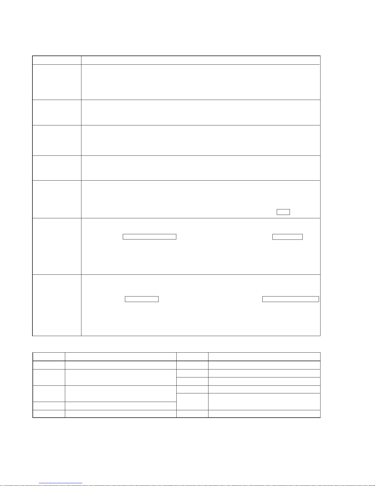
ITEMS OF ERROR HISTORY MODE ITEMS AND CONTENTS
Selecting the Test Mode
Display
total rec
total play
retry err
total err
err history
er refresh
tm refresh
Details of History
No error
Read error. PTOC cannot be read
(DISC ejected)
TOC error. UTOC error
(DISC not ejected)
Loading error
Address cannot be read (Servo has deviated)
Displays the recording time.
Displayed as “rππππππh”.
The displayed time is the total time the laser is set to the high power state.
This is about 1/4 of the actual recording time.
The time is displayed in decimal digits from 0h to 65535h.
Displays the play time.
Displayed as “pππππππh”. The time displayed is the total actual play time. Pauses are not counted.
The time is displayed in decimal digits from 0h to 65535h.
Displays the total number of retries during recording and number of retry errors during play.
Displayed as “rππ pππ”.
“r” indicates the retries during recording while “p” indicates the retry errors during play.
The number of retries and retry errors are displayed in hexadecimal digits from 00 to FF.
Displays the total number of errors.
Displayed as “total ππ”.
The number of errors is displayed in hexadecimal digits from 00 to FF.
Displays the 10 latest errors.
Displayed as “0π E@@”.
π indicates the history number. The smaller the number, the more recent is the error. (00 is the latest).
@@ indicates the error code.
Refer to the following table for the details. The error history can be switched by rotating the AMS dial.
Mode which erases the “retry err”, “total err”, and “err history” histories.
When returning the unit to the customer after completing repairs, perform this to erase the past error history,
After pressing the MD W ALKMAN SYNC button and “er refresh?” is displayed, press the ENTER/YES button
to erase the history.
“Complete!” will be displayed momentarily.
Be sure to check the following when this mode has been executed.
• The data has been erased.
• The mechanism operates normally when recording and play are performed.
Mode which erases the “total rec” and “total play” histories.
These histories serve as approximate indications of when to replace the optical pickup.
If the optical pickup has been replaced, perform this operation and erase the history.
After pressing the ENTER/AMS button and “tm refresh?” is displayed, press the MD WALKMAN SYNC
button to erase the history.
“Complete!” will be displayed momentarily.
Be sure to check the following when this mode has been executed.
• The data has been erased.
• The mechanism operates normally when recording and play are performed.
Table of Error Codes
Error Code
E00
E01
E02
E03
E04
E05
E06
E07
E08
E09
E0A
FOK has deviated
Cannot focus (Servo has deviated)
Recording retry
Recording retry error
Playback retry error
(Access error)
Play retry error (C2 error)
Details of Error
Error Code
Details of Error
Page 5
– 5 –
4-216-211-0π AEP, UK, G, CIS
4-216-211-1π E, SP, MY, HK, AR
4-216-211-2π US, CND, KR, AUS
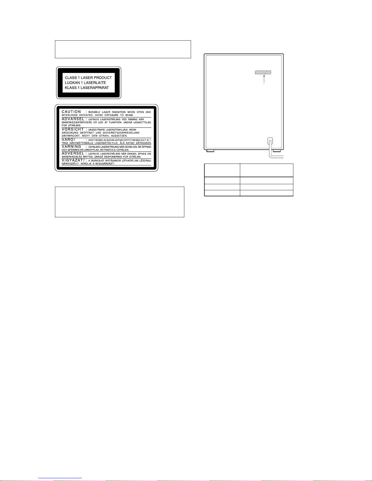
MODEL IDENTIFICATION
— BACK PANEL —
• Abbreviation
CND : Canadian model
G : German model
SP : Singapore model
MY : Malaysia model
HK : Hong Kong model
AR : Argentine model
KR : Korea model
AUS : Australian model
Parts No.
PAR TS No.
MODEL
SAFETY-RELATED COMPONENT WARNING !!
COMPONENTS IDENTIFIED BY MARK ! OR DO TTED LINE
WITH MARK ! ON THE SCHEMATIC DIAGRAMS AND IN
THE PARTS LIST ARE CRITICAL TO SAFE OPERATION.
REPLACE THESE COMPONENTS WITH SONY PARTS
WHOSE PART NUMBERS APPEAR AS SHOWN IN THIS
MANUAL OR IN SUPPLEMENTS PUBLISHED BY SONY.
ATTENTION AU COMPOSANT AYANT RAPPORT
À LA SÉCURITÉ!!
LES COMPOSANTS IDENTIFIÉS P AR UNE MARQUE ! SUR
LES DIAGRAMMES SCHÉMATIQUES ET LA LISTE DES
PIÈCES SONT CRITIQUES POUR LA SÉCURITÉ DE
FONCTIONNEMENT. NE REMPLACER CES COMPOSANTS
QUE PAR DES PIÈCES SONY DONT LES NUMÉROS
SONT DONNÉS DANS CE MANUEL OU DANS LES
SUPPLÉMENTS PUBLIÉS P AR SONY.
CAUTION
Use of controls or adjustments or performance of procedures
other than those specified herein may result in hazardous radiation exposure.
Notes on chip component replacement
• Never reuse a disconnected chip component.
• Notice that the minus side of a tantalum capacitor may be
damaged by heat.
Flexible Circuit Board Repairing
• Keep the temperature of soldering iron around 270˚C
during repairing.
• Do not touch the soldering iron on the same conductor of the
circuit board (within 3 times).
• Be careful not to apply force on the conductor when soldering
or unsoldering.
Laser component in this product is capable of emitting radiation
exceeding the limit for Class 1.
This appliance is classified as
a CLASS 1 LASER product.
The CLASS 1 LASER PRODUCT MARKING is located on
the rear exterior.
This caution
label is located
inside the unit.
Page 6
– 6 –
NOTES ON HANDLING THE OPTICAL PICK-UP BLOCK
OR BASE UNIT
The laser diode in the optical pick-up block may suffer electrostatic
break-down because of the potential difference generated by the
charged electrostatic load, etc. on clothing and the human body.
During repair, pay attention to electrostatic break-down and also
use the procedure in the printed matter which is included in the
repair parts.
The flexible board is easily damaged and should be handled with
care.
NOTES ON LASER DIODE EMISSION CHECK
The laser beam on this model is concentrated so as to be focused on
the disc reflective surface by the objective lens in the optical pickup block. Therefore, when checking the laser diode emission, observe from more than 30 cm away from the objective lens.
LASER DIODE AND FOCUS SEARCH OPERATION
CHECK
Carry out the “S curve check” in “CD section adjustment” and check
that the S curve waveform is output four times.
SAFETY CHECK-OUT
After correcting the original service problem, perform the following safety checks before releasing the set to the customer:
Check the antenna terminals, metal trim, “metallized” knobs, screws,
and all other exposed metal parts for AC leakage. Check leakage as
described below.
LEAKAGE
The AC leakage from any exposed metal part to earth Ground and
from all exposed metal parts to any exposed metal part having a
return to chassis, must not exceed 0.5 mA (500 microampers). Leakage current can be measured by any one of three methods.
1. A commercial leakage tester, such as the Simpson 229 or RCA
WT-540A. Follow the manufacturers’ instructions to use these
instruments.
2. A battery-operated AC milliammeter. The Data Precision 245
digital multimeter is suitable for this job.
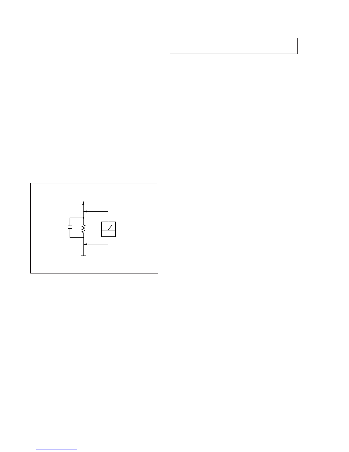
3. Measuring the voltage drop across a resistor by means of a VOM
or battery-operated AC voltmeter . The “limit” indication is 0.75
V, so analog meters must have an accurate low-voltage scale.
The Simpson 250 and Sanwa SH-63Trd are examples of a passive VOM that is suitable. Nearly all battery operated digital
multimeters that have a 2V AC range are suitable. (See Fig. A)
Fig. A. Using an AC voltmeter to check AC leakage.
0.15µF
To Exposed Metal
Parts on Set
1.5k
Ω
AC
voltmeter
(0.75V)
Earth Ground
Page 7

– 7 –
TABLE OF CONTENTS
1. SERVICING NOTE .......................................................... 8
2. GENERAL ........................................................................ 14
3. DISASSEMBLY
3-1. Loading Panel ..................................................................... 16
3-2. MD Mechanism and Front Panel ........................................ 16
3-3. Cassette Lid and Tape Mechanism...................................... 17
3-4. MD Link, Power SW, CD Panel Boards and
Display Board ..................................................................... 17
3-5. Disc Tray.............................................................................18
3-6. Slider (CAM) ...................................................................... 18
3-7. Base Unit (MBU-5A) and BD (MD) Board ....................... 19
3-8. SW Board and Loading Motor (M103) .............................. 19
4. SERVICE MODE ............................................................ 20
5. TEST MODE (MD) ......................................................... 22
6. MECHANICAL ADJUSTMENTS ..........................26
7. ELECTRICAL ADJUSTMENTS ............................... 27
8. DIAGRAMS
8-1. Circuit Boards Location ......................................................40
8-2. Block Diagrams
• BD (CD) Section.............................................................. 41
• BD (MD) Section (1) ....................................................... 43
• BD (MD) Section (2) ....................................................... 45
• Main Section ....................................................................47
• Deck Section ....................................................................49
• Display Section ................................................................51
• Main Power/Sub Power Section ...................................... 53
8-3. Printed Wiring Board – BD (CD) Section – ....................... 57
8-4. Schematic Diagram – BD (CD) Section – .......................... 59
8-5. Printed Wiring Board – BD (MD) Section – ...................... 61
8-6. Schematic Diagram – BD (MD) (1/2) Section – ................ 63
8-7. Schematic Diagram – BD (MD) (2/2) Section – ................ 65
8-8. Schematic Diagram – Main (1/4) Section – ........................67
8-9. Schematic Diagram – Main (2/4) Section – ........................69
8-10. Schematic Diagram – Main (3/4) Section – ..................... 71
8-11. Schematic Diagram – Main (4/4) Section – ..................... 73
8-12. Printed Wiring Board – Main Section – ........................... 75
8-13. Printed Wiring Board – Deck Section – ........................... 77
8-14. Schematic Diagram – Deck Section – ..............................79
8-15. Printed Wiring Board – Leaf SW Section – ..................... 81
8-16. Schematic Diagram – Leaf SW Section – ........................ 81
8-17. Schematic Diagram – Display (1/2) Section – ................. 83
8-18. Schematic Diagram – Display (2/2) Section – ................. 85
8-19. Printed Wiring Board – Display Section – ....................... 87
8-20. Printed Wiring Board – MD Digital Section –.................89
8-21. Schematic Diagram – MD Digital (1/2) Section – ........... 91
8-22. PSchematic Diagram – MD Digital (2/2) Section –.........93
8-23. Schematic Diagram – BD Switch Section –..................... 95
8-24. Printed Wiring Board – BD Switch Section –.................. 96
8-25. Printed Wiring Board – CD Motor Section – ...................97
8-26. Schematic Diagram – CD Motor Section –......................99
8-27. Printed Wiring Board – MD Link Section –................... 101
8-28. Schematic Diagram – MD Link Section – ..................... 103
8-29. Schematic Diagram – Power Section – .......................... 105
8-30. Printed Wiring Board – Power Section – ....................... 107
8-31. IC Block Diagrams .........................................................109
8-32. IC Pin Functions .............................................................112
9. EXPLODED VIEWS
9-1. Case Section......................................................................119
9-2. Chassis Section ................................................................. 120
9-3. Front Panel Section ........................................................... 121
9-4. CD Mechanism Deck Section-1 (CDM38LH-5BD32L) .. 122
9-5. CD Mechanism Deck Section-2 (CDM38LH-5BD32L) .. 123
9-6. Base Unit Section (BU-5BD32L) ..................................... 124
9-7. TC Mechanism Section-1 (TCM230AWR2/230PWR2) .. 125
9-8. TC Mechanism Section-2 (TCM230AWR2/230PWR2) .. 126
9-9. MD Mechanism Section-1 (MDM-5A) ............................ 127
9-10. MD Mechanism Section-2 (MDM-5A) .......................... 128
10. ELECTRICAL PARTS LIST ...............................129
Page 8
– 8 –
CD-TEXT
This unit is provided with a simple CD-TEXT display function.
The CD-TEXT contents of 50 tracks are displayed on the fluorescent display tube.
Since the function is simple, some special characters may not be displayed, or may be displayed as other characters.
SECTION 1
SERVICING NOTE
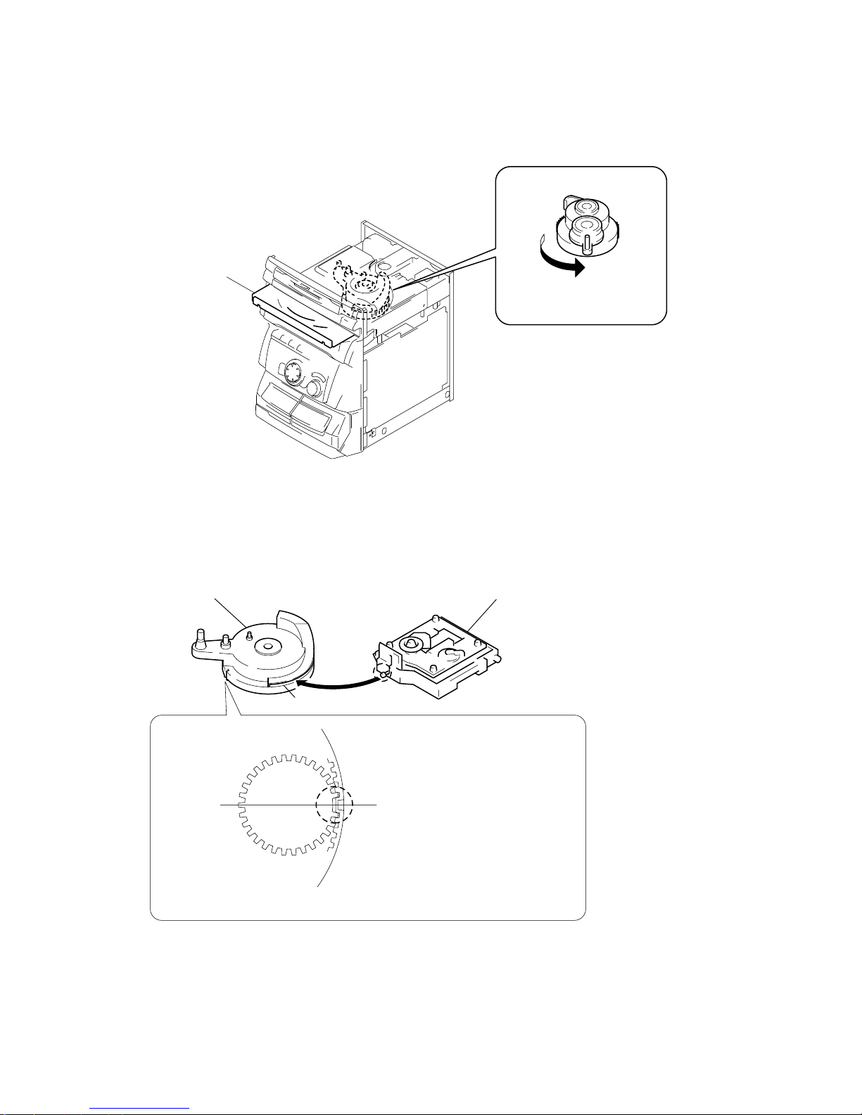
HOW TO OPEN THE DISC TRAY WHEN POWER SWITCH
TURNS OFF
NOTE FOR INSTALLATION (ROTARY ENCODER)
3
Pull-out the disc tray.
1
Remove the Case.
2
Turn the cam to the direction
of arrow.
BU cam
Groove
Section A
Note:When attaching the Base unit, Insert the
section A into the groove of BU cam.
Note:When attaching the BU cam,
engage the Rotary encoder
switch as shown in the figure.
Page 9
– 9 –
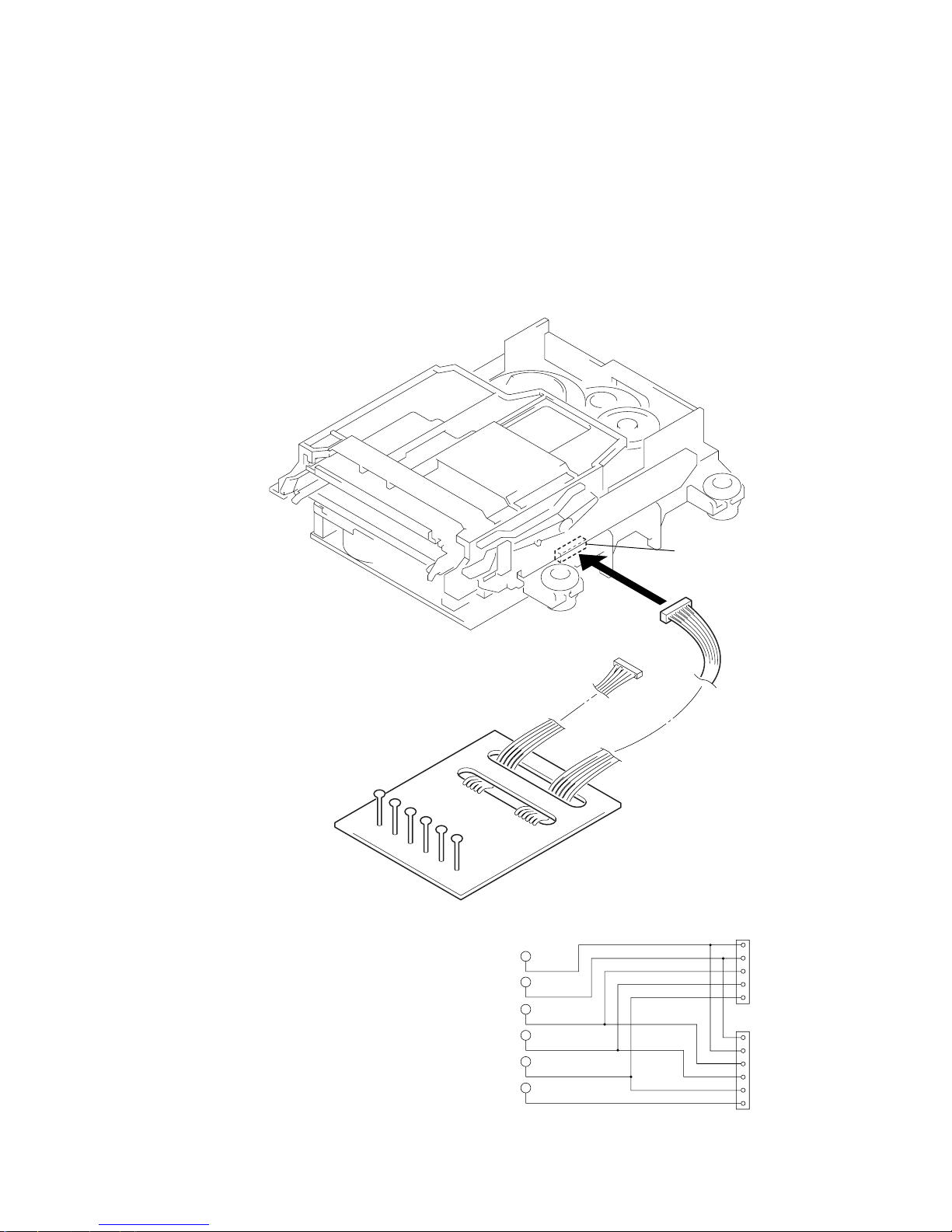
JIG FOR CHECKING BD BOARD WAVEFORM
The special jig (J-2501-149-A) is useful for checking the waveform of the BD board. The names of terminals and the checking items to be
performed are shown as follows.
GND : Ground
I+3V : For measuring IOP (Check the deterioration of the optical pick-up laser)
IOP : For measuring IOP (Check the deterioration of the optical pick-up laser)
TEO : TRK error signal (Traverse adjustment)
VC : Reference level for checking the signal
RF : RF signal (Check jitter)
RF
VC
TEO For MDM-
3
For MDM-5
IOP
I-3V
VC
RF
TEO
IOP
I+3V
GND
VC
RF
TEO
IOP
I+3V
GND
1
5
1
6
CN110
RF
5P connector
6P connecto
r
VC
TEO
IOP
I+3V
GND
Mechanism deck
Page 10

– 10 –
IOP DATA RECORDING AND DISPLAY WHEN OPTICAL PICK-UP AND NON-VOLATILE MEMORY (IC171 OF
BD BOARD) ARE REPLACED
The IOP value labeled on the optical pick-up can be recorded in the non-volatile memory. By recording the value, it will eliminate the need
to look at the value on the label of the optical pick-up. When replacing the optical pick-up or non-volatile memory (IC171 of BD board),
record the IOP value on the optical pick-up according to the following procedure.
Record Precedure:
1. With the power ON, press the CD-MD SYNC button while pressing the p and ENTER/YES buttons together.
2. Rotate the AMS dial to display “Service”, and press the ENTER/YES button.
3. Rotate the AMS dial to display “lop.Write”, and press the ENTER/YES button.
4. The display becomes “Ref=@@@.@” (@ is an arbitrary number) and the numbers which can be changed will blink.
5. Input the IOP value written on the optical pick-up.
To select the number : Rotate the AMS dial.
To select the digit : Press the MD WALKMAN SYNC button.
6. When the ENTER/YES button is pressed, the display becomes “Measu=@@@.@” (@ is an arbitrary number).
7. As the adjustment results are recorded for the 6 value. Leave it as it is and press the ENTER/YES button.
8. “Complete!” will be displayed momentarily. The value will be recorded in the non-volatile memory and the display will become “Iop
Write”.
9. Press the REPEAT/STEREO/MONO button to complete.
Display Precedure:
1. With the power ON, press the CD-MD SYNC button while pressing the p and ENTER/YES buttons together.
2. Rotate the AMS dial to display “Service”, and press the YES button.
3. Rotate the AMS dial to display “lop.Read”.
4. “@@.@/##.#” is displayed and the recorded contents are displayed.
@@.@ : indicates the Iop value labeled on the pick-up.
##.# : indicates the Iop value after adjustment
5. To end, press the MD WALKMAN SYNC button or MENU/NO button to display “Iop Read”. Then press the REPEAT/STEREO/
MONO button.
Page 11
– 11 –
• 0.9 mW power
Specified value : 0.84 to 0.92 mW
• 7.0 mW power
Specified value : 6.8 to 7.2 mW
lop (at 7mW)
• Labeled on the optical pickup
Iop value ± 10mA
• Traverse waveform
Specified value : Below 10% offset
• Error rate check
Specified value : For points a, b, and c
C1 error : Below 220
AD error : Below 2
• Error rate check
Specified value:
a.When using test disc (MDW-74/AU-1)
C1 error : Below 80
AD error : Below 2
b.When using check disc (TDYS-1)
C1 error : Below 50
• CPLAY error rate check
Specified value:
C1 error : Below 80
AD error : Below 2
• Unsatisfactory if displayed as T=@@ (##) NG”
NG
(@@, ## are both arbitrary numbers)
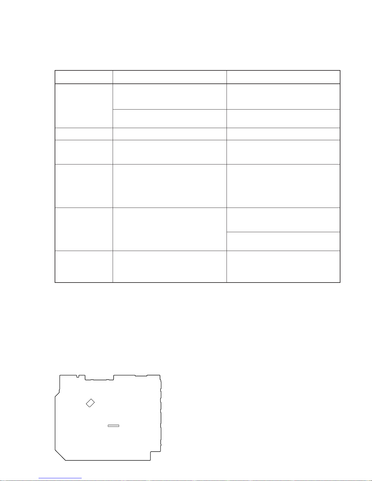
CHECKS PRIOR TO PARTS REPLACEMENT AND ADJUSTMENTS
Before performing repairs, perform the following checks to determine the faulty locations up to a certain extent.
Details of the procedures are described in “5 Electrical Adjustments”.
Laser power check
(7-6-2 : See page 29)
Traverse check
(7-6-3 : See page 29)
Focus bias check
(7-6-4 : See page 30)
C PLAY check
(7-6-5 : See page 30)
Self-recording/playback
check
(REC/PLAY)
(7-6-6 : See page 30)
TEMP check
(Temperature
compensation
offset check)
(7-6-1 : See page 29)
Criteria for Determination
(Unsatisfactory if specified value is not satisfied)
• Clean the optical pick-up
• Adjust again
• Replace the optical pick-up
• Replace the optical pick-up
• Replace the optical pick-up
• Replace the optical pick-up
• Replace the optical pick-up
If always unsatisfactory:
• Replace the overwrite head
• Check for disconnection of the circuits around the
overwrite head
If occasionally unsatisfactory:
• Check if the overwrite head is distorted
• Check the mechanism around the sled
• Check for disconnection of the circuits around D101
(BD board)
• Check the signals around IC101, IC121, CN102,
CN103 (BD board)
Measure if unsatisfactory:
Note:
The criteria for determination above is intended merely to determine if satisfactory or not, and does not serve as the specified value for
adjustments.
When performing adjustments, use the specified values for adjustments.
FORCED RESET
The system microprocessor can be reset in the following procedure.
Use these procedure when the unit cannot be operated normally due to the overrunning of the microprocessor, etc.
Procedure :
Disconnect the power plug, short-circuit both edge of BT921.
[MAIN BOARD] (Component Side)
IC801
BT921
Page 12
– 12 –
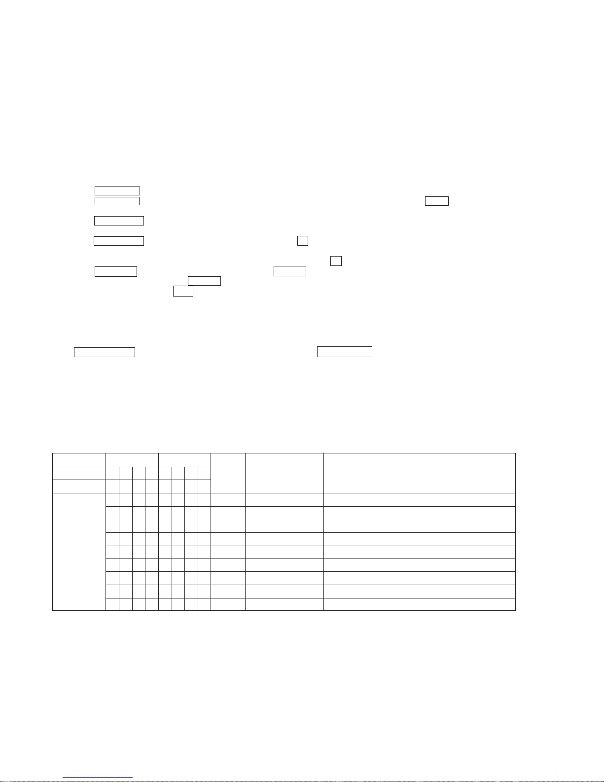
RETRY CAUSE DISPLAY MODE
• In this test mode, the causes for retry of the unit during recording can be displayed on the fluorescent indicator tube. During playback, the
“track mode” for obtaining track information will be set.
This is useful for locating the faulty part of the unit.
• The following will be displayed :
During recording and stop : Retry cause, number of retries, and number of retry errors.
During playback : Information such as type of disc played, part played, copyright.
These are displayed in hexadecimal.
Precedure:
1. Load a recordable disc whose contents can be erased into the unit.
2. Press the FUNCTION button and set the function to “MD”.
3. Press the MENU/NO button. When “Edit/Menu” is displayed on the fluorescent indicator tube, rotate the AMS dial to display “All
Erase?”.
4. Press the ENTER/YES button.
5. “All Erase??” is displayed on the fluorescent indicator tube.
6. Press the ENTER/YES button to display “Complete!!”, and press the p button immediately. Wait for about 10 seconds while pressing
the button.
7. When the “TOC” displayed on the fluorescent display tube goes off, release the p button.
8. Press the REC (MD) button to start recording. Then press the ^/MD button and start recording.
9. To check the “track mode”, press the ^/MD button to start play.
10. To exit the test mode, press the 1/u button, and turn OFF the power. When “TOC” disappears, disconnect the power plug from the
outlet. If the test mode cannot be exited, refer to “Forced Reset” on page 8.
} Address (Physical address on disc)
Hexadecimal
Bit
Binary
Higher Bits Lower Bits
84218421
b7 b6 b5 b4 b3 b2 b1 b0
00000001
00000010
00000100
00001000
00010000
00100000
01000000
10000000
When track jump (shock) is detected
When ADER was counted more than five times
continuously
When ADIP address is not continuous
When DIN unlock is detected
When not in focus
When ABCD signal level exceeds the specified range
When CLV is unlocked
When access operation is not performed normally
Hexa-
decimal
shock
ader5
Discontinuous address
DIN unlock
FCS incorrect
IVR rec error
CLV unlock
Access fault
Cause of Retry Occurring conditions
01
02
04
08
10
20
40
80
Fig. 1 Reading the Test Mode Display
(During recording and stop)
RTs@@c##c**
Fluorescent display tube display
@@ : Cause of retry
## : Number of retries
** : Number of retry errors
Fig. 2 Reading the Test Mode Display
(During playback)
@@####**$$
Fluorescent display tube display
@@ : Parts No. (name of area named on T OC)
## : Cluster
** : Sector
$$ : Track mode (Track information such as copyright infor-
mation of each part)
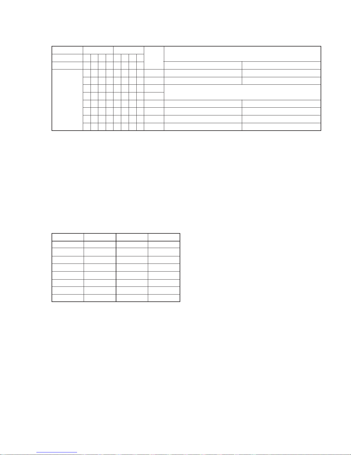
Reading the Retry Cause Display
Reading the Display:
Convert the hexadecimal display into binary display. If more than two causes, they will be added.
Example
When 42 is displayed:
Higher bit : 4 = 0100 n b6
Lower bit : 2 = 0010 n b1
In this case, the retry cause is combined of “CLV unlock” and “ader5”.
When A2 is displayed:
Higher bit : A = 1010 n b7+b5
Lower bit : 2 = 0010 n b2
The retry cause in this case is combined of “access fault”, “IVR rec error”, and “ader5”.
Page 13
– 13 –
Hexadecimal
Bit
Binary
Higher Bits Lower Bits
84218421
b7 b6 b5 b4 b3 b2 b1 b0
00000001
00000010
00000100
00001000
00010000
00100000
01000000
10000000
Hexa-
decimal
Details
01
02
04
08
10
20
40
80
Emphasis OFF
Monaural
This is 2-bit display. Normally 01.
01:Normal audio. Others:Invalid
Audio (Normal)
Original
Copyright
Write prohibited
When 0 When 1
Emphasis ON
Stereo
Invalid
Digital copy
No copyright
Write allowed
Reading the Display:
Convert the hexadecimal display into binary display. If more than two causes, they will be added.
Example When 84 is displayed:
Higher bit : 8 = 1000 n b7
Lower bit : 4 = 0100 n b2
In this case, as b2 and b7 are 1 and others are 0, it can be determined that the retry cause is combined of “emphasis OFF”, “monaural”,
“original”, “copyright exists”, and “write allowed”.
Example When 07 is displayed:
Higher bit : 0 = 1000 n All 0
Lower bit : 7 = 0111 n b0+b1+b2
In this case, as b0, b1, and b2 are 1 and others are 0, it can be determined that the retry cause is combined of “emphasis ON”, “stereo”,
“original”, “copyright exists”, and “write prohibited”.
Hexadecimal n Binary Conversion Table
Hexadecimal Binary Hexadecimal Binary
0
1
2
3
4
5
6
7
8
9
A
B
C
D
E
F
0000
0001
0010
0011
0100
0101
0110
0111
1000
1001
1010
1011
1100
1101
1110
1111
Reading the Track Mode Display
Page 14
– 14 –
SECTION 2
GENERAL
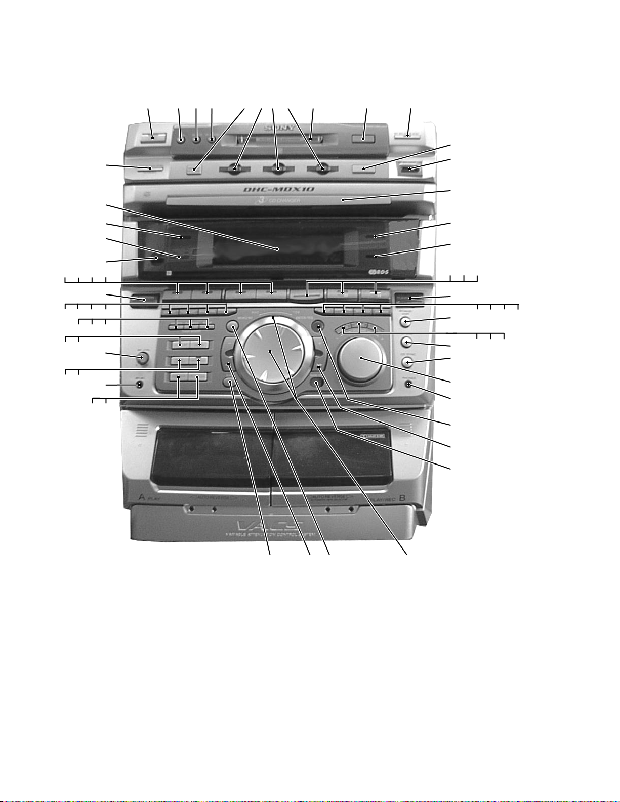
Front Panel
7
56
910
811
12
13
14
15
16
17
24
25
26
27
19
20
21
18
22
23
28
31
30
29
32
231
33
34
38
41
42
40
35
3639 37
51
52
43
47
5354
44
45
46
4849
50
4
57
55
56
58
59
60
61
62
63
64
Page 15
– 15 –
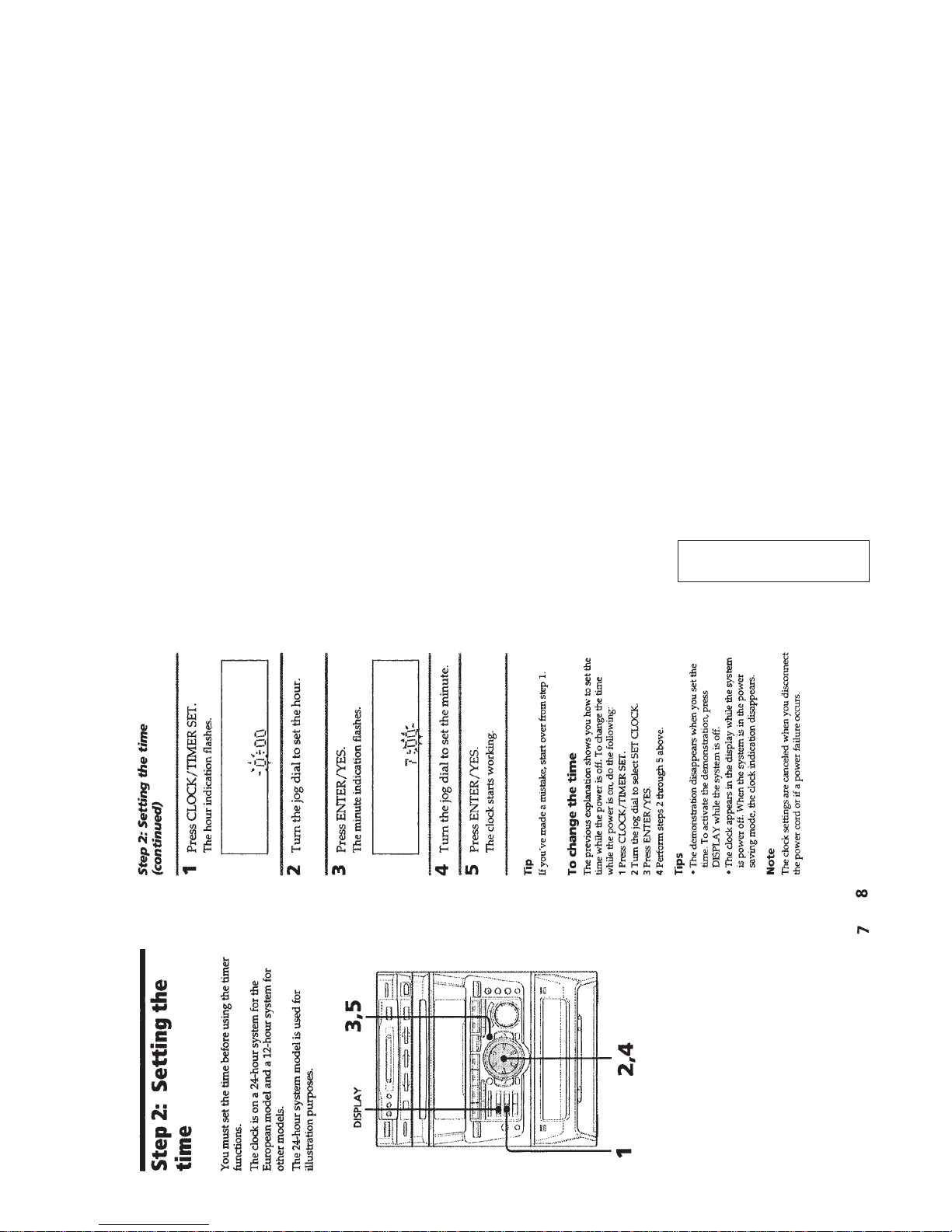
This section is extracted from
instruction manual.
LOCATION OF PARTS AND CONTROLS
1 1/u (POWER) button and indicator
2 REC button and indicator
3 REC IT button
4 CD-MD SYNC button
5 DISC SKIP/EX-CHANGE button
6 DISC 1 button and indicator
7 DISC 2 button and indicator
8 DISC 3 button and indicator
9 Disk compartment
10 § (Eject) (MD) button
11 MD WALKMAN SYNC button
12 § (Eject) (CD) button
13 MD WALKMAN LINK jack
14 Disc tray
15 SYNC BASS HIGH indicator
16 SYNC BASS LOW indicator
17 p button
18 ^/CD button and indicator
19 ^/MD button and indicator
20 TUNER/BAND button and indicator
21 CD NON-STOP button and indicator
22 KARAOKE PON/MPX button
23 SYNC EQ button
24 SYNC BASS button
25 REC P AUSE/START button and
indicator
26 DBFB button
27 GROOVE button
28 SURROND button
29 HI DUB button
30 CD-TAPE SYNC button
31 VOLUME knob
32 PHONES jack
33 ENTER/YES button and indicator
34 ) + button and indicator
35 NAME EDIT/CHAR button
36 JOG/0x) dial and
indicator
37 MENU/NO button
38 ) – button and indicator
39 CLEAR button
40 CD FLASH button
41 CD LOOP button
42 MIX MIC jack
43 TIMER SELECT button and indicator
44 CLOCK/TIMER SET button
45 MIC LEVEL knob
46 SPECTRUM ANAL YZER button
47 DISPLAY button
48 REPEAT STEREO/MONO button
49 DOLBY NR/PLAY MODE/PTY button
50 DIRECTION/EDIT/TUNER MEMORY
button
51 P FILE MEMORY button
52 GEQ CONTROL button
53 FILE SELECT button
54 EFFECT button
55 FUNCTION button and indicator
56 9/TAPE B button and indicator
57 (/TAPE B button and indicator
58 9/TAPE A button and indicator
59 (/TAPE A button and indicator
60 Remote sensor
61 SYNC EQ indicator
62 EFFECT indicator
63 Display Window
64 POWER SAVE/DEMO (STANDBY)
button
Page 16
– 16 –
SECTION 3
DISASSEMBLY
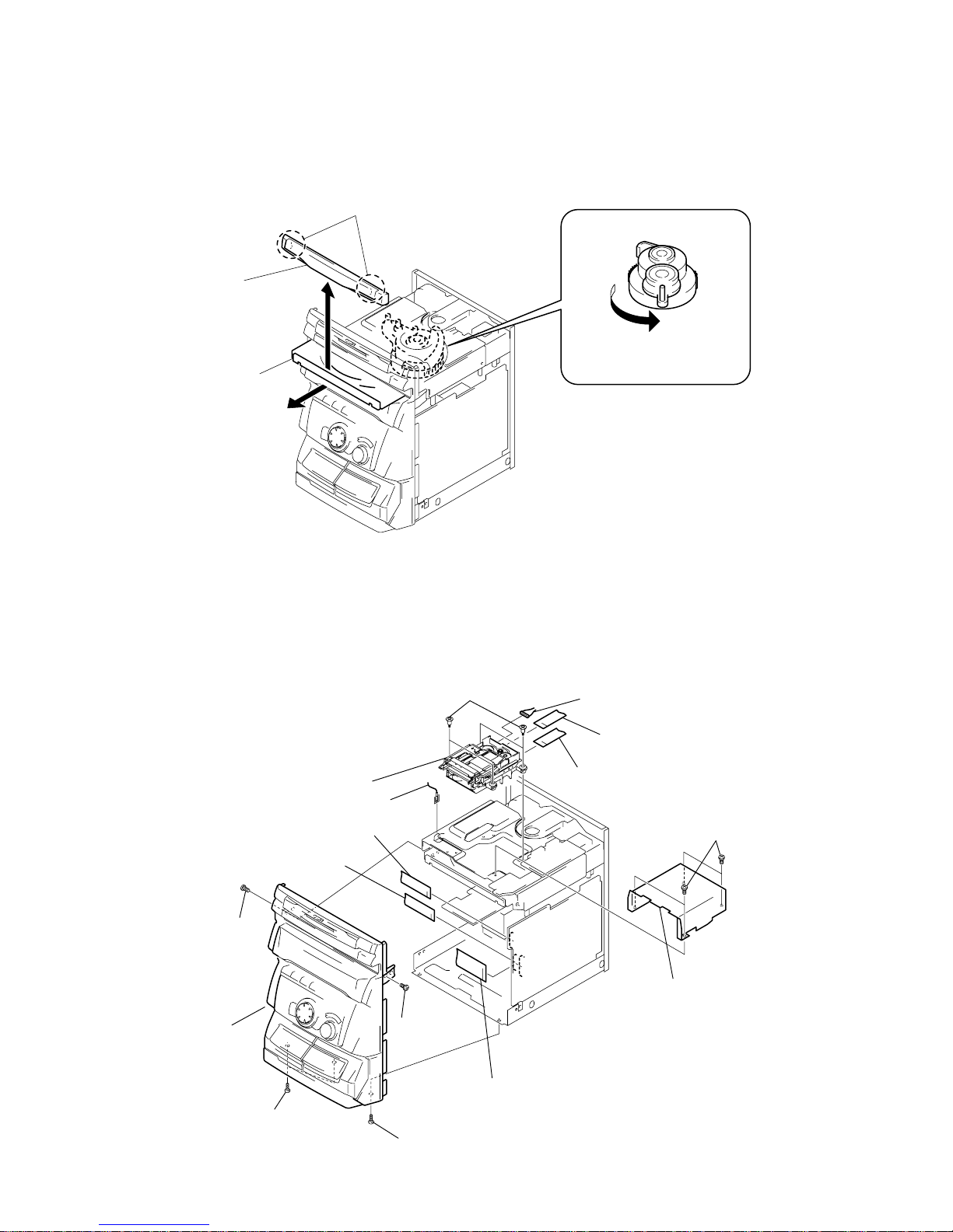
Note: Follow the disassembly procedure in the numerical order given.
3-1. LOADING PANEL
3-2. MD MECHANISM AND FRONT PANEL
3
Loading panel
2
Pull-out the disc tray.
Claws
1
Turn the cam to the direction
of arrow.
9
Screw (BVTT3x6
)
0
Two screws
(BVTT3x6)
!§
Front panel
!™
Screw (BVTP 3x10)
!¡
Screw
(BVTP 3x10)
1
Four screws
(BVTP 3x8)
3
Wire
4
Flat type wire
(CN102)
6
Connector
(CN601)
5
Flat type wire
(CN103)
!£
Flat type wire
(CN501)
!¢
Flat type wire
(CN304)
!∞
Flat type wire
(CN303)
7
Four step screws
8
MD mechanism
2
Bracket (MDM)
Page 17
– 17 –
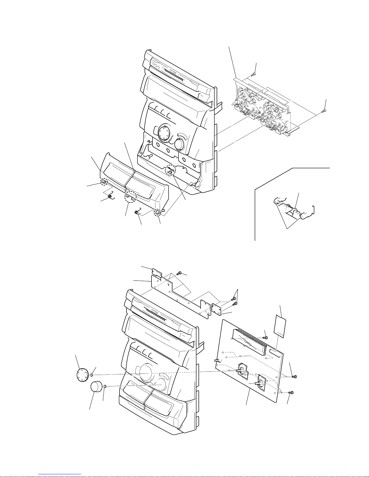
3-3. CASSETTE LID AND TAPE MECHANISM
3-4. MD LINK, POWER SW, CD PANEL BOARDS AND DISPLAY BOARD
1
Release
3
Cassette lid (R) block
4
Cassette lidr (L) block
Portion
A
Portion
A
5
Spring (R)
7
T wo screws
(BVTP2.6x8)
8
Three screws
(BVTP2.6x8)
9
T ape mechanism
6
Spring (L)
2
Releas
Note for installation
Portion
B
Portion
B
6
Knob (Jog)
7
Knob (Vol)
!¡
Three screws
(BVTP2.6x8)
5
CD Panel board
(Two claws)
4
Power SW board
(Two claws)
3
MD link SW board
(Three claws)
!¢
Display board
0
Flat type wire
(CN601)
1
Four screws
(BVTP2.6x8)
2
Four screws
(BVTP2.6x8)
!™
Four screws
(BVTP2.6x8)
!£
Six screws
(BVTP2.6x8)
9
Nut
8
Nut
Page 18
– 18 –
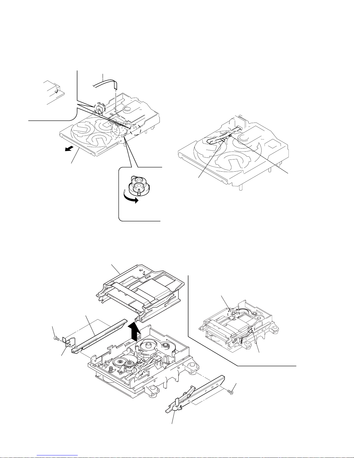
3-5. DISC TRAY
3-6. SLIDER (CAM)
(Perform after removing the front panel.) Note:When installing the Disc tray, pull around the flat type wire to
pass through the claw
A
and claw B, as shown in the figure.
Claw
B
Claw
A
1
Turn the cam the
direction of arrow.
2
Pull-out the disc tray.
5
Remove the disc tray.
4
Two claws
3
Flat type wire (8 core)
1
Two screws (BTP2.6x6)
2
Bracket (Guide L)
3
Leaf spring
5
Bracket (Guide R)
6
Slider (Cam)
4
Two screws (BTP2.6x6)
Set the shaft of Lever (O/C) to
be at the position in the figure.
Set the shaft of Cam gear to
be at the position in the figure.
Page 19
– 19 –
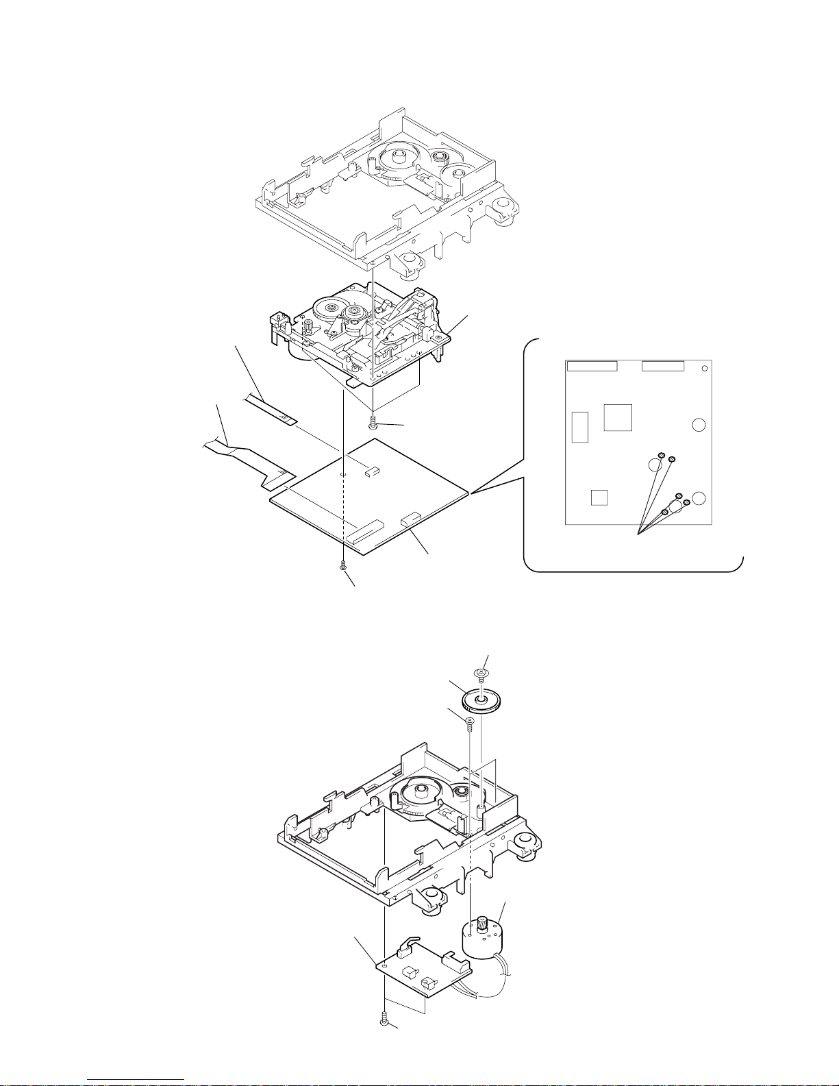
3-7. BASE UNIT (MBU-5A) AND BD (MD) BOARD
3-8. SW BOARD AND LOADING MOTOR (M103)
1
Three screws
(BTP2.6x6)
2
Base unit (MBU-5A)
3
Remove the solder (Five portion)
4
Screw (M1.7x4)
6
Flexible board
(CN101)
7
BD (MD) board
5
Flexible board
(CN104)
5
Two screws (BTP2.6x6)
6
SW board
4
Loading motor (M103)
3
Two screws
(PWH1.7x3)
1
Screw (PTPWH M2.6x6)
2
Gear B
Page 20

– 20 –
SECTION 4
SERVICE MODE
MC Cold Reset
• The cold reset clears all data including preset data stored in the RAM to initial conditions. Execute this mode when returning the set to the
customer.
Procedure:
1. Press three buttons p , ENTER/YES , and 1/u simultaneously.
2. “COLD RESET” is displayed on the fluorescent display tube and reset is executed.
CD Delivery Mode
• This mode moves the optical pick-up to the position durable to vibration. Use this mode when returning the set to the customer after repair.
Procedure:
1. Press 1/u button to turn the set ON.
2. Press CD LOOP button and 1/u button simultaneously.
3. A message “LOCK” is displayed on the fluorescent indicator tube, and the CD delivery mode is set.
MC Hot Reset
• This mode resets the set with the preset data kept stored in the memory . The hot reset mode functions same as if the power cord is plugged
in and out.
Procedure:
1. Press three buttons p , ENTER/YES , and DISC 1 simultaneously.
2. The fluorescent indicator tube becomes blank instantaneously, and the set is reset.
Sled Servo Mode
• This mode can run the CD sled motor freely. Use this mode, for instance, when cleaning the pick-up.
Procedure:
1. Press 1/u button to turn the set ON.
2. Press three buttons p , ENTER/YES , and § (CD) simultaneously.
3. The Sled Servo mode is selected, if “CD” is blanking on the fluorescent indicator tube.
4. With the CD in stop status, When the ≠ AMS ± knob is rotated in the clockwise direction, the optical pick-up moves outside.
When rotated counterclockwise, it moves inside.
5. To exit from this mode, perform as follows:
1) Move the optical pick-up to the most inside track.
2) Execute MC cold reset. (Press the three buttons p , ENTER/YES , and 1/u button simultaneously.)
Note:
• Always move the pick-up to most inside track when exiting from this mode. Otherwise, a disc will not be unloaded.
• Do not run the sled motor excessively, otherwise the gear can be chipped.
Change-over of AM Tuner Step between 9kHz and 10kHz
• A step of AM channels can be changed over between 9kHz and 10kHz.
Procedure:
1. Press 1/u button to turn the set ON.
2. Select the function “TUNER”, and press TUNER/BAND button to select the BAND “AM”.
3. Press 1/u button to turn the set OFF.
4. Press ENTER/YES and 1/u buttons simultaneously, and the display of fluorescent indicator tube changes to “AM 9k STEP” or “AM
10k STEP”, and thus the channel step is changed over.
LED and Fluorescent Indicator Tube All Lit, Key Check Mode
Procedure:
1. Press three buttons p , ENTER/YES , and DISC 2 simultaneously.
2. LEDs and fluorescent indicator tube are all turned on.
Press DISC 2 button, and the key check mode is activated.
3. In the key check mode, the fluorescent indicator tube displays “K 0 V0 J0”. Each time a button is pressed, “K”value increases. However ,
once a button is pressed, it is no longer taken into account.
“J” Value increases like 1, 2, 3 ... if rotating ≠ AMS ± knob in “+” direction, or it decreases like 0, 9, 8 ... if rotating in “-”
direction.
“V” Value increases like 1, 2, 3 ... if rotating VOLUME knob in “+” direction, or it decreases like 0, 9, 8 ... if rotating in “-” direction.
4. To exit from this mode, press three buttons in the same manner as step 1, or disconnect the power cord.
Page 21

– 21 –
AMS Test Mode
• This mode is used for checking the AMS operations of the tape deck.
JIG
7-819-039-12 Alignment tape, AMS-110A
Procedure:
1. Press the 1/u button to turn the unit ON.
2. Set the tape (AMS-110A).
3. Press the three buttons p , ENTER/YES , and DISC 3 button simultaneously.
4. “TEST MODE” is displayed on the fluorescent display tube.
5. Press the FUNCTION button and switch the function to the deck with the tape (AMS-110A).
6. Press the CD SYNC button. “AMS CHECK” is displayed on the fluorescent display tube and the tape is rewound.
7. AMS starts in the normal direction. If the AMS count is 2 at shut down, proceed to step 8.
“NG” is displayed at other times, and the deck stops.
8. AMS starts in the opposite direction. If the AMS count is 2 at shut down again, “OK” is displayed.
“NG” is displayed at other times.
Note: The p button of CD section will become effective and the aging of CD section will stop sometime, if the buttons described in step 3
are not pressed simultaneously. In that case, press ^/CD button and operate the CD section.
Page 22

– 22 –
SECTION 5
TEST MODE (MD)
5-1. PRECAUTIONS FOR USE OF TEST MODE
• As loading related operations will be performed regardless of the test mode operations being performed, be sure to check that the disc is
stopped before setting and removing it.
Even if the §EJECT (MD) button is pressed while the disc is rotating during continuous playback, continuous recording, etc., the disc
will not stop rotating.
Therefore, it will be ejected while rotating.
Be sure to press the §EJECT (MD) button after pressing the MENU/NO button and the rotation of disc is stopped.
5-1-1. Recording laser emission mode and operating buttons
• Continuous recording mode (CREC MODE)
• Laser power check mode (LDPWR CHECK)
• Laser power adjustment mode (LDPWR ADJUST)
• Traverse (MO) check (EF MO CHECK)
• Traverse (MO) adjustment (EF MO ADJUST)
• When pressing the REC (MD) button.
5-2. SETTING THE TEST MODE
The following are two methods of entering the test mode.
Procedure 1:With the power ON, press the CD-MD SYNC button while pressing the p and ENTER/YES buttons together.
When the test mode is set, “Check” will be displayed. Rotating the AMS dial switches between the following four groups;
···Nn Check Nn Adjust Nn Service Nn Develop Nn ···.
Procedure 2:With the power ON, press the REC (MD) button while pressing the p and ENTER/YES buttons together.
When the test mode is set, “TEMP CHECK” will be displayed. By setting the test mode using this procedure, only the “Check”
group of procedure 1 can be executed.
5-3. EXITING THE TEST MODE
Press the REPEAT/STEREO/MONO button.
5-4. BASIC OPERATIONS OF THE TEST MODE
All operations are performed using the AMS dial, ENTER/YES button, and MENU/NO button.
The functions of these buttons are as follows.
Function name
AMS dial
ENTER/YES button
MENU/NO button
Function
Changes parameters and modes
Proceeds onto the next step. Finalizes input.
Returns to previous step. Stops operations.
Page 23
– 23 –
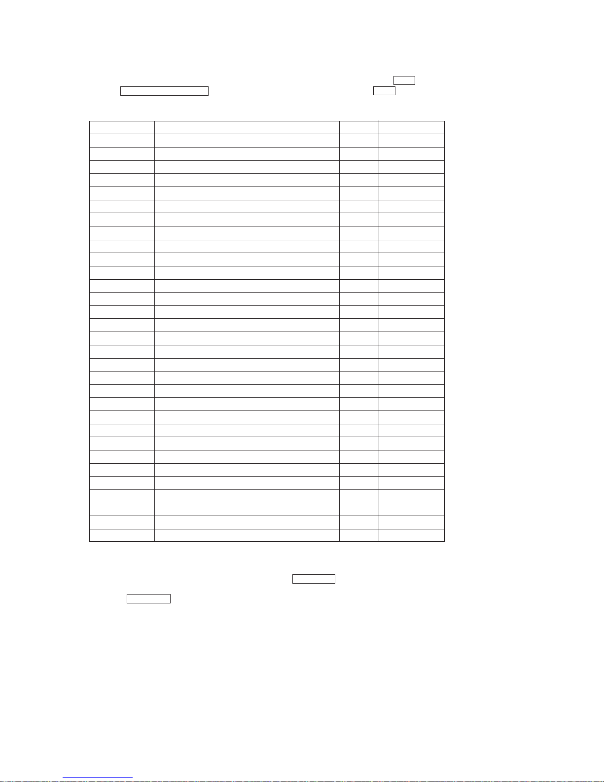
5-5. SELECTING THE TEST MODE
There are 31 types of test modes as shown below. The groups can be switched by rotating the AMS dial. After selecting the group to be used,
press the MD WALKMAN SYNC button. After setting a certain group, rotating the AMS dial switches between these modes.
Refer to “Group” in the table for details selected.
All items used for servicing can be treated using group S. So be carefully not to enter other groups by mistake.
Display
TEMP CHECK
LDPWR CHECK
EF MO CHECK
EF CD CHECK
FBIAS CHECK
S curve CHECK
VERIFY MODE
DETRK CHECK
TEMP ADJUST
LDPWR ADJUST
EF MO ADJUST
EF CD ADJUST
FBIAS ADJUST
EEP MODE
MANUAL CMD
SVDATA READ
ERR DP MODE
SLED MOVE
ACCESS MODE
0920 CHECK
HEAD ADJUST
CPLA Y2 MODE
CREC2 MODE
ADJ CLEAR
AG Set (MO)
AG Set (CD)
Iop Read
Iop Write
INFORMATION
CPLAY MODE
CREC MODE
Contents
Temperature compensation offset check
Laser power check
Traverse (MO) check
Traverse (CD) check
Focus bias check
S letter check
Non-volatile memory check
Detrack check
Temperature compensation offset adjustment
Laser power adjustment
Traverse (MO) adjustment
Traverse (CD) adjustment
Focus bias adjustment
Non-volatile memory control
Command transmission
Status display
Error history display, clear
Sled check
Access check
Outermost circumference check
Head position check
Same functions as CPLAY MODE
Same functions as CREC MODE
Initialization of non-volatile memory of adjustment value
Auto gain output level adjustment (MO)
Auto gain output level adjustment (CD)
IOP data display
IOP data write
Microprocessing version display
Continuous play mode
Continuous recording mode
Mark
(X)
(X)
(X)
(X) (!)
(X)
(X)
(X)
(X)
(X)
(X)
(X)
(X)
Group (*)
CS
CS
CS
CS
CS
C
C
C
AS
AS
AS
AS
AS
D
D
D
S
D
D
D
D
D
D
AS
AS
AS
CS
AS
CS
CASD
CASD
• For details of each adjustment mode, refer to “5. Electrical Adjustments”.
For details of “ERR DP MODE”, refer to “Self-Diagnosis Function” on page 3.
• If a different mode has been selected by mistake, press the MENU/NO button to exit that mode.
• Modes with (X) in the Mark column are not used for servicing and therefore are not described in detail. If these modes are set accidentally,
press the MENU/NO button to exit the mode immediately. Be especially careful not to set the modes with (!) as they will overwrite the
non-volatile memory and reset it, and as a result, the unit will not operate normally.
Group (*)
C: Check
S: Service
A: Adjust
D: Develop
Page 24

– 24 –
“CPLAY MID” n “CPLAY OUT” n “CPLAY IN”
“CPLAY MID” n “CPLAY OUT” n “CPLAY IN”
5-5-1. Operating the Continuous Playback Mode
1. Entering the continuous playback mode
1 Set the disc in the unit. (Whichever recordable discs or discs for playback only are available.)
2 Rotate the AMS dial and display “CPLAY MODE”.
3 Press the ENTER/YES button to change the display to “CPLAY MID”.
4 When access completes, the display changes to “C1 = AD = ”.
Note : The numbers “ ” displayed show you error rates and ADER.
2. Changing the parts to be played back
1 Press the ENTER/YES button during continuous playback to change the display as below.
When pressed another time, the parts to be played back can be moved.
2 When access completes, the display changes to “C1 = AD = ”.
Note : The numbers “ ” displayed show you error rates and ADER.
3. Ending the continuous playback mode
1 Press the MENU/NO button. The display will change to “CPLAY MODE”.
2 Press the §EJECT (MD) button to remove the disc.
Note : The playback start addresses for IN, MID, and OUT are as follows.
IN 40h cluster
MID 300h cluster
OUT 700h cluster
5-5-2. Operating the Continuous Recording Mode (Use only when performing self-recording/palyback check.)
1. Entering the continuous recording mode
1 Set a recordable disc in the unit.
2 Rotate the AMS dial and display “CREC MODE”.
3 Press the ENTER/YES button to change the display to “CREC MID”.
4 When access completes, the display changes to “CREC ( )” and “REC” indicator lights up.
Note : The numbers “ ” displayed shows you the recording position addresses.
2. Changing the parts to be recorded
1 When the ENTER/YES button is pressed during continuous recording, the display changes as below.
When pressed another time, the parts to be recorded can be changed. “REC” indicator goes off.
2 When access completes, the display changes to “CREC ( )” and “REC” indicator lights up.
Note : The numbers “ ” displayed shows you the recording position addresses.
3. Ending the continuous recording mode
1 Press the MENU/NO button. The display changes to “CREC MODE” and “REC” indicator goes off.
2 Press the §EJECT (MD) button to remove the disc.
Note 1 : The recording start addresses for IN, MID, and OUT are as follows.
IN 40h cluster
MID 300h cluster
OUT 700h cluster
Note 2 :The MENU/NO button can be used to stop recording anytime.
Note 3 :Do not perform continuous recording for long periods of time above 5 minutes.
Note 4 :During continuous recording, be careful not to apply vibration.
5-5-3. Non-Volatile Memory Mode (EEP MODE)
This mode reads and writes the contents of the non-volatile memory.
It is not used in servicing. If set accidentally, press the MENU/NO button immediately to exit it.
Page 25
– 25 –
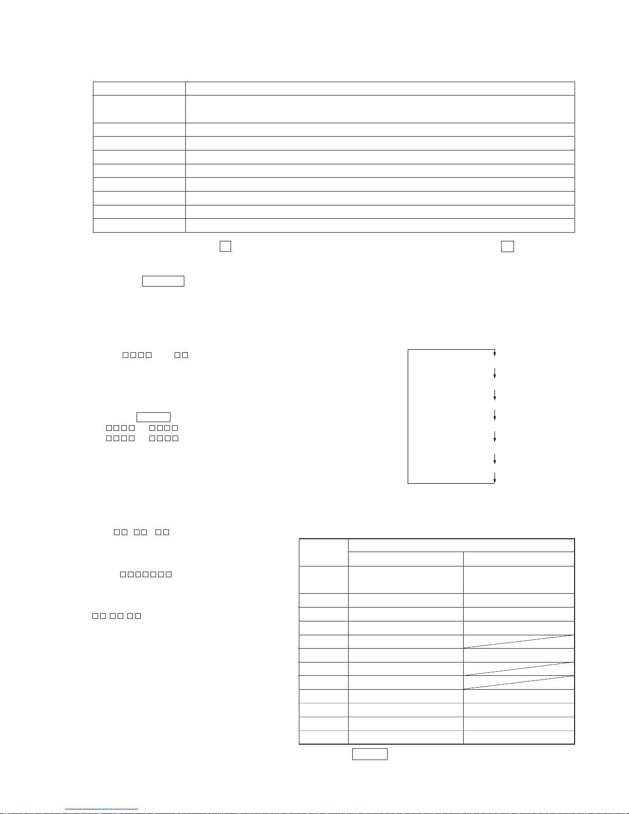
MEANINGS OF OTHER DISPLAYS
Mode display
Error rate display
Address display
Auto gain display (Not used in servicing)
Detrack check display (Not used in servicing)
IVR display (Not used in servicing)
5-6. FUNCTIONS OF OTHER BUTTONS
Contents
Sets continuous playback when pressed in the STOP state. When pressed during continuous playback, the tracking servo turns
ON/OFF.
Stops continuous playback and continuous recording.
The sled moves to the outer circumference only when this is pressed.
The sled moves to the inner circumference only when this is pressed.
Switches between the pit and groove modes when pressed.
Switches the spindle servo mode (CLV S ˜ CLV A).
Switches the displayed contents each time the button is pressed
Ejects the disc
Exits the test mode
Function
^/MD
p
) *
0 *
CLEAR
PLAY MODE
DISPLAY
§ EJECT (MD)
REPEAT/STEREO/MONO
* This function works only when the p button is pressed and “MD” is displayed. In other cases, it works everytime the p button is pressed.
5-7. TEST MODE DISPLAYS
Each time the DISPLAY button is pressed, the display changes in the following order.
1. Mode display
Displays “TEMP ADJUST”, “CPLAYMODE”, etc.
2. Error rate display
Displays the error rate in the following way.
C1 = AD =
C1 = Indicates the C1 error.
AD = Indicates ADER.
3. Address display
The address is displayed as follows. (MO:recordable disc, CD:playback only disc)
Pressing the CLEAR button switches between the groove display and pit display.
h = s = (MO pit and CD)
h = a = (MO groove)
h = Indicates the header address.
s = Indicates the SUBQ address.
a = Indicates the ADIP address.
Note: “–” is displayed when servo is not imposed.
4. Auto gain display (Not used in servicing)
The auto gain is displayed as follows.
AG = /
5. Detrack check display (Not used in servicing)
The detrack is displayed as follows.
ADR =
6. IVR display (Not used in servicing)
The IVR is displayed as follows.
^/MD *
^/MD *
REC
SYNC
L-SYNC
OVER
1
REPEAT
TRACK
DISC
SHUFFLE
MONO
When Off
Contents
Display
When Lit
During continuous playback
(CLV: ON) (Green)
Tracking servo OFF (Unber)
Recording mode ON
CLV low speed mode
ABCD adjustment completed
Tracking offset cancel ON
Tracking auto gain OK
Focus auto gain OK
Pit
High reflection
CLV S
CLV LOCK
STOP (CLV: OFF) (Light off)
Tracking servo ON (Green)
Recording mode OFF
CLV normal mode
Tracking offset cancel OFF
Groove
Low reflection
CLV A
CLV UNLOCK
* Differentiate ^/MD by the color of the button indicator.
Page 26

– 26 –
Precaution
1. Clean the following parts with a denatured alcohol-moistened
swab:
record/playback heads pinch rollers
erase head rubber belts
capstan idlers
2. Demagnetize the record/playback head with a head demagnetizer.
3. Do not use a magnetized screwdriver for the adjustments.
4. After the adjustments, apply suitable locking compound to the
parts adjusted.
5. The adjustments should be performed with the rated power supply voltage unless otherwise noted.
Torque Measurement
31 to 71 g • cm
(0.43 – 0.98 oz • inch)
2 to 6 g • cm
(0.02 – 0.08 oz • inch)
31 to 71 g • cm
(0.43 – 0.98 oz • inch)
2 to 6 g • cm
(0.02 – 0.08 oz • inch)
71 to 143 g • cm
(0.98 – 1.99 oz • inch)
100 g or more
(3.53 oz or more)
100 g or more
(3.53 oz or more)
SECTION 6
MECHANICAL ADJUSTMENTS
Mode
FWD
Torque meter
CQ-102C
Meter reading
FWD
back tension
REV
REV
back tension
FF/REW
FWD tension
REV tension
CQ-102C
CQ-102RC
CQ-102RC
CQ-201B
CQ-403A
CQ-403R
Page 27
– 27 –
MD SECTION
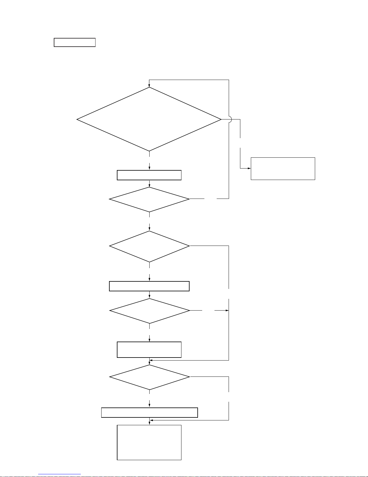
7-1. PARTS REPLACEMENT AND ADJUSTMENT
• Check and adjust the MDM and MBU as follows.
The procedure changes according to the part replaced
SECTION 7
ELECTRICAL ADJUSTMENTS
• Abbreviation
OP : Optical pick-up
OWH: Overwrite head
• Temperature compensation offset check
• Laser power check
• Traverse check
• Focus bias check
• C PLAY check
• Self-recording/playback check
Parts Replacement and Repair
NG
Has the OWH been replaced?
NO
OK
NO
NO
NO
Has OP, IC171, IC101, or
IC121 been replaced?
YES
YES
Initial setting of the adjustment value
Has OP or IC171 been replaced?
YES
IOP information recording
(IOP value labeled on OP)
Has IC171 or D101
been replaced?
YES
Temperature compensation offset adjustment
• Laser power adjustment
• Traverse adjustment
• Focus bias adjustment
• Error rate adjustment
• Focus bias check
• Auto gain adjustment
Check the sleding and spindle
mechanisms.
Other causes can be suspected.
Page 28
– 28 –
7-2. PRECA UTIONS FOR CHECKING LASER DIODE
EMISSINON
To check the emission of the laser diode during adjustments, never
view directly from the top as this may lose your eye-sight.
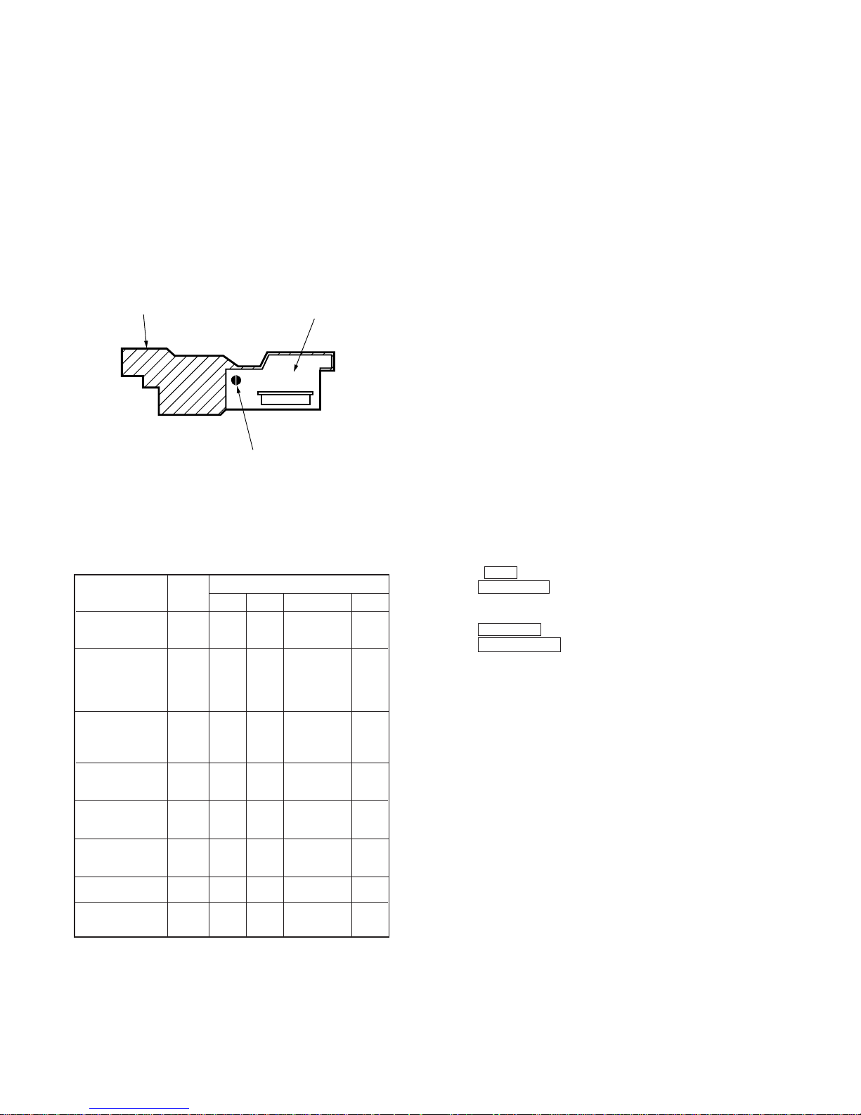
7-3. PRECAUTIONS FOR USE OF OPTICAL PICK-
UP (KMS-260A)
As the laser diode in the optical pick-up is easily damaged by static
electricity, solder the laser tap of the flexible board when using it.
Before disconnecting the connector, desolder first. Before connecting the connector, be careful not to remove the solder. Also take
adequate measures to prevent damage by static electricity. Handle
the flexible board with care as it breaks easily.
Optical pick-up flexible board
7-4. PRECAUTIONS FOR ADJUSTMENTS
1) When replacing the following parts, perform the adjustments
and checks with ¬ in the order shown in the following table.
Optical
Pick-up
BD Board
IC101, IC121
D101
IC171
¬G¬¬
pick-up
flexible board
laser tap
1. Initial setting of
adjustment value
2.Recording of IOP
information
(Value written in
the pick-up)
3.Temperature
compensation
offset adjustment
4.Laser power
adjustment
5.Traverse
adjustment
6.Focus bias
adjustment
7.Error rate check
8. Auto gain output
level adjustment
IC192
G
¬G¬GG
¬¬GGG
¬G¬¬¬
¬G¬¬G
¬G¬¬G
¬G¬¬G
¬G¬¬G
2) Set the test mode when performing adjustments.
After completing the adjustments, exit the test mode.
Perform the adjustments and checks in “group S” of the test mode.
3) Perform the adjustments to be needed in the order shown.
4) Use the following tools and measuring devices.
• Check Disc (MD) TDYS-1
(Parts No. 4-963-646-01)
• Test Disk (MDW-74/AU-1) (Parts No. 8-892-341-41)
• Laser power meter LPM-8001 (Parts No. J-2501-046-A)
or
MD Laser power meter 8010S (Parts No. J-2501-145-A)
• Oscilloscope (Measure after performing CAL of prove.)
• Digital voltmeter
• Thermometer
• Jig for checking BD board waveform
(Parts No. : J-2501-149-A)
5) When observing several signals on the oscilloscope, etc.,
make sure that VC and ground do not connect inside the oscilloscope.
(VC and ground will become short-circuited.)
6) Using the above jig enables the waveform to be checked without
the need to solder.
(Refer to Servicing Note on page 9.)
7) As the disc used will affect the adjustment results, make sure
that no dusts nor fingerprints are attached to it.
Note:
When performing laser power checks and adjustment (electrical
adjustment), use of the new MD laser power meter 8010S (J-2501145-A) instead of the conventional laser power meter is convenient.
It sharply reduces the time and trouble to set the laser power meter
sensor onto the objective lens of the optical pick-up.
7-5. CREATING CONTINUOUSL Y RECORDED DISC
* This disc is used in focus bias adjustment and error rate check.
The following describes how to create a continuous recording disc.
1. Insert a disc (blank disc) commercially available.
2. Rotate the AMS dial and display “CREC MODE”.
3. Press the ENTER/YES button again to display “CREC MID”.
Display “CREC (0300)” and start to recording.
4. Complete recording within 5 minutes.
5. Press the MENU/NO button and stop recording .
6. Press the §EJECT (MD) button and remove the disc.
The above has been how to create a continuous recorded data for
the focus bias adjustment and error rate check.
Note :
• Be careful not to apply vibration during continuous recording.
Page 29
– 29 –
7-6. CHECKS PRIOR TO REPAIRS
These ch ecks a re pe rforme d before replacing parts according to
“approximate specifications” to determine the faulty locations. For
details, refer to “Checks Prior to Parts Replacement and
Adjustments” (See page 11).
7-6-1. Temperature Compensation Offset Check
When performing adjustments, set the internal temperature and room
temperature to 22 to 28°C.
Checking Procedure:
1. Rotate the AMS dial to display “TEMP CHECK”.
2. Press the ENTER/YES button.
3. “T=@@(##) OK” should be displayed. If “T=@@ (##) NG” is
displayed, it means that the results are bad.
(@@ indicates the current value set, and ## indicates the value
written in the non-volatile memory.)
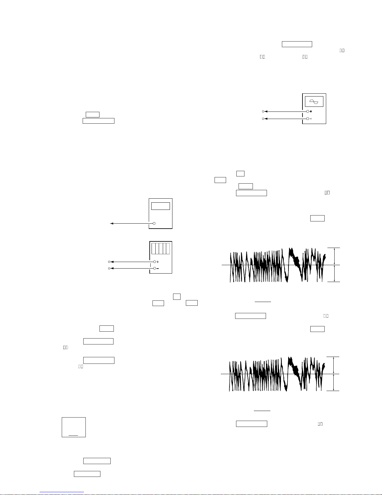
7-6-2. Laser Power Check
Before checking, check the IOP value of the optical pick-up.
(Refer to 7-8. Recording and Displaying IOP Information.)
Connection :
KMS
260A
27X40
B0825
N
Iop = 82.5 mA in this case
Iop (mA) = Digital voltmeter reading (mV)/1 (Ω)
Checking Procedure:
1. Set the laser power meter on the objective lens of the optical
pick-up. (When it cannot be set properly, press the p button
and display the “MD”, and then press the 0 button or )
button to move the optical pick-up.)
Connect the digital volt meter to CN110 pin 5 (I+3V) and
CN110 pin 4 (IOP).
2. Then, rotate the AMS dial and display “LDPWR CHECK”
(C02).
3. Press the ENTER/YES button once and display “LD 0.9 mW $
”. Check that the reading of the laser power meter become
0.84 to 0.92 mW.
4. Press the ENTER/YES button once more and display “LD 7.0
mW $ ”. Check that the reading the laser power meter and
digital volt meter satisfy the specified value.
Specified Value :
Laser power meter reading : 7.0 ± 0.2 mW
Digital voltmeter reading : Optical pick-up displayed value ± 10%
(Optical pick-up label)
5. Press the MENU/NO button and display “LDPWR CHECK”
and stop the laser emission.
(The MENU/NO button is effective at all times to stop the laser
emission.)
(For details of the method for checking
this value, refer to “7-8. Recording and
Displaying IOP Information”.)
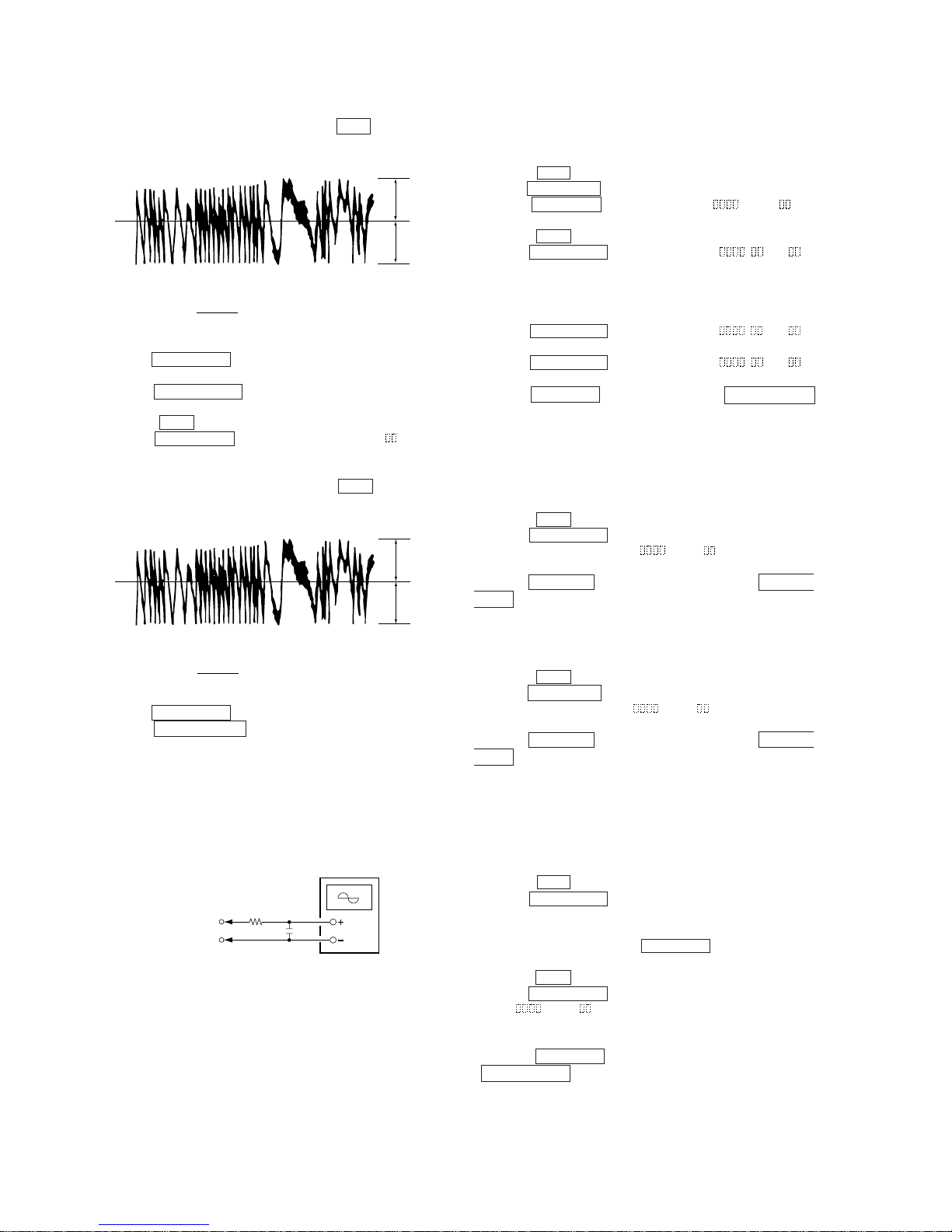
7-6-3. T raverse Check
Connection :
Checking Procedure:
1. Connect an oscilloscope to CN110 pin 3 (TE) and CN110 pin
1 (VC) of the BD board.
2. Load a disc (any available on the market). (Refer to Note 1.)
3. Press the p button and display the “MD”, and then press the
) button and move the optical pick-up outside the pit.
4. Rotate the AMS dial and display “EF MO CHECK”(C03).
5. Press the ENTER/YES button and display “EFB =
MO-R”.
(Laser power READ power/Focus servo ON/tracking servo OFF/
spindle (S) servo ON)
6. Observe the waveform of the oscilloscope, and check that the
specified value is satisfied. Do not rotate the AMS dial.
(Read power traverse checking)
(Traverse Waveform)
7. Press the ENTER/YES button and display “EFB =
MO-W”.
8. Observe the waveform of the oscilloscope, and check that the
specified value is satisfied. Do not rotate the AMS dial.
(Write power traverse checking)
(Traverse Waveform)
9. Press the ENTER/YES button display “EFB =
MO-P”.
Then, the optical pick-up moves to the pit area automatically
and servo is imposed.
Note 1: After step 4, each time the ENTER/YES button is pressed,
the display will be switched between “LD 0.7 mW $ ”,
“LD 6.2 mW $ ”, and “LD WP $ ”. Nothing needs to
be performed here.
Laser power
meter
Optical pick-up
objective lens
Digital volt mete
r
BD board
CN110 pin
5
(I+3V)
CN110 pin
4
(IOP)
V : 0.5 V/div
H : 10 ms/div
Input : DC mod
e
Oscilloscope
BD board
CN110 pin
3
(TE)
CN110 pin
1
(VC)
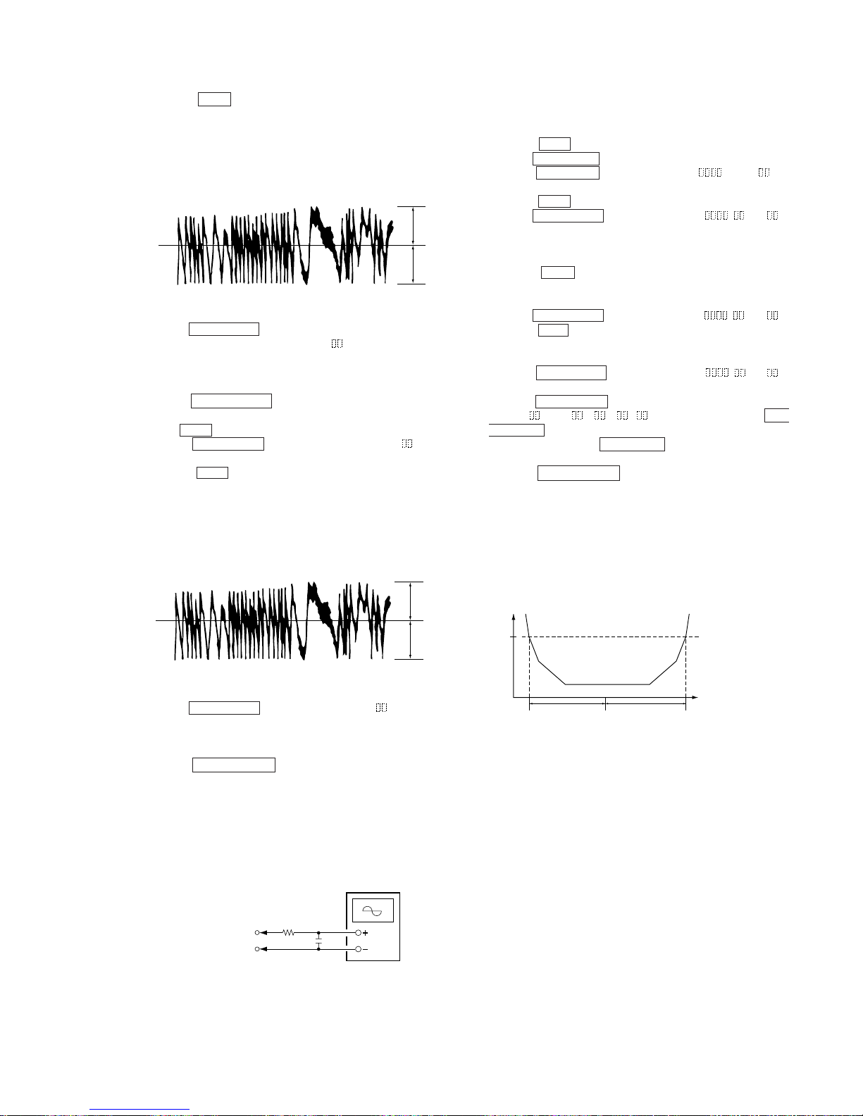
VC
A
B
Specified value : Below 10% offset value
Offset value (%) = X 100
I
A – B
I
2 (A + B)
VC
A
B
Specified value : Below 10% offset value
Offset value (%) = X 100
I
A – B
I
2 (A + B)
Page 30
– 30 –
10.Observe the waveform of the oscilloscope, and check that the
specified value is satisfied. Do not rotate the AMS dial.
(Traverse Waveform)
11. Press the ENTER/YES button display “EF MO CHECK”
The disc stops rotating automatically.
12. Press the §EJECT (MD) button and remove the disc.
13. Load the check disc (MD) TDYS-1.
14. Roteto the AMS dial and display “EF CD CHECK”.
15. Press the ENTER/YES button and display “EFB = CD”.
Servo is imposed automatically.
16. Observe the waveform of the oscilloscope, and check that the
specified value is satisfied. Do not rotate the AMS dial.
(Traverse Waveform)
17. Press the ENTER/YES button and display “EF CD CHECK”.
18. Press the §EJECT (MD) button and remove the check disc
(MD) TDYS-1.
Note 1 : MO reading data will be erased during if a recorded disc is
used in this adjustment.
Note 2 : If the traverse waveform is not clear, connect the oscillo-
scope as shown in the following figure so that it can be
seen more clearly.
7-6-4. Focus Bias Check
Change the focus bias and check the focus tolerance amount.
Checking Procedure :
1. Load a test disk (MDW-74/AU-1).
2. Rotate the AMS dial and display “CPLAY MODE”.
3. Press the ENTER/YES button twice and display “CPLA Y MID”.
4. Press the MENU/NO button when “C1 = AD = ” is
displayed.
5. Rotate the AMS dial and display “FBIAS CHECK”.
6. Press the ENTER/YES button and display “ / c = ”.
The first four digits indicate the C1 error rate, the two digits
after “/” indicate ADER, and the 2 digits after “c =” indicate the
focus bias value.
Check that the C1 error is below 220 and ADER is below 2.
7. Press the ENTER/YES button and display “ / b = ”.
Check that the C1 error is below 220 and ADER is below 2.
8. Press the ENTER/YES button and display “ / a = ”.
Check that the C1 error is below 220 and ADER is below 2.
9. Press the MENU/NO button, next press the §EJECT (MD)
button, and remove the test disc.
7-6-5. C PLAY Checking
MO Error Rate Check
Checking Procedure :
1. Load a test disk (MDW-74/AU-1).
2. Rotate the AMS dial and display “CPLAY MODE”.
3. Press the ENTER/YES button and display “CPLAY MID”.
4. The display changes to “C1 =
AD = ”.
5. If the C1 error rate is below 80, check that ADER is below 2.
6. Press the MENU/NO button, stop playback, press the §EJECT
(MD) button, and test disc.
CD Error Rate Check
Checking Procedure :
1. Load a check disc (MD) TDYS-1.
2. Rotate the AMS dial and display “CPLAY MODE”.
3. Press the ENTER/YES button twice and display “CPLA Y MID”.
4. The display changes to “C = AD = ”.
5. Check that the C1 error rate is below 50.
6. Press the MENU/NO button, stop playback, press the §EJECT
(MD) button, and the test disc.
7-6-6. Self-Recording/playback Check
Prepare a continuous recording disc using the unit to be repaired
and check the error rate.
Checking Procedure :
1. Insert a recordable disc (blank disc) into the unit.
2. Rotate the AMS dial to display “CREC MODE”.
3. Press the ENTER/YES button to display the “CREC MID”.
4. When recording starts, “REC” is displayed, this becomes “CREC
(@@@@)" (@@@@) is the address), and recording starts.
5. About 1 minute later, press the MENU/NO button to stop continuous recording.
6. Rotate the AMS dial to display “C PLAY MODE”.
7. Press the ENTER/YES button to display “C PLAY MID”.
8. “C1 = AD = ” will be displayed.
9. Check that the C1 error becomes below 80 and the AD error
below 2.
10. Press the MENU/NO button to stop playback, and press the
§EJECT (MD) button and remove the disc.
VC
A
B
Specified value : Below 10% offset value
Offset value (%) = X 100
I
A – B
I
2 (A + B)
VC
A
B
Specified value : Below 10% offset value
Offset value (%) = X 100
I
A – B
I
2 (A + B)
330 k
Ω
Oscilloscop
e
10pF
BD board
CN110 pin
3
(TE)
CN110 pin
1
(VC)
Page 31

– 31 –
7-7. INITIAL SETTING OF ADJUSTMENT VALUE
Note:
Mode which sets the adjustment results recorded in the non-volatile
memory to the initial setting value. However the results of the
temperature compensation offset adjustment will not change to the
initial setting value.
If in itial set ting is perfor med, perfor m all adjust ments again
excluding the temperature compensation offset adjustment.
For details of the initial setting, refer to “7-4. Precautions on Adjustments” and execute the initial setting before the adjustment as
required.
Setting Procedure :
1. Rotate the AMS dial to display “ADJ CLEAR”.
2. Press the ENTER/YES button. “Complete!” will be displayed
momentarily and initial setting will be executed, after which
“ADJ CLEAR” will be displayed.
7-8. RECORDING AND DISPLAYING THE IOP
INFORMATION
The IOP data can be recorded in the non-volatile memory . The IOP
value on the label of the optical pickup and the IOP value after the
adjustment will be recorded. Recording these data eliminates the
need to read the label on the optical pick-up.
Recording Procedure :
1. With the power ON, press the CD-MD SYNC button while
pressing the p and ENTER/YES buttons together.
2. Rotate the AMS dial to display “Service”, and press the ENTER/YES button.
3. Rotate the AMS dial to display “Iop.Write”, and press the
ENTER/YES button.
4. The display becomes Ref=@@@.@ (@ is an arbitrary number)
and the numbers which can be changed will blink.
5. Input the IOP value written on the optical pick-up.
To select the number : Rotate the AMS dial.
To select the digit : Press the MD MALKMAN SYNC button.
6. When the ENTER/YES button is pressed, the display becomes
“Measu=@@@.@” (@ is an arbitrary number).
7. As the adjustment results are recorded for the 6 value. Leave it
as it is and press the ENTER/YES button.
8. “Complete!” will be displayed momentarily. The value will be
recorded in the non-volatile memory and the display will become
“Iop Write”.
Display Procedure :
1. Rotate the AMS dial to display “Iop.Read”.
2. “@@.@/##.#” is displayed and the recorded contents are
displayed.
@@.@ indicates the Iop value labeled on the pick-up.
##.# indicates the Iop value after adjustment
3. To end, press the MD MALKMAN SYNC button or MENU/
NO button to display “Iop Read”.
7-9. TEMPERATURE COMPENSATION OFFSET
ADJUTMENT
Save the temperature data at that time in the non-volatile memory
as 25 ˚C reference data.
Note :
1. Usually, do not perform this adjustment.
2. Perform this adjustment in an ambient temperature of 22 ˚C to
28 ˚C. Perform it immediately after the power is turned on when
the internal temperature of the unit is the same as the ambient
temperature of 22 ˚C to 28 ˚C.
3. When D101 has been replaced, perform this adjustment after
the temperature of this part has become the ambient temperature.
Adjusting Procedure :
1. Rotate the AMS dial and display “TEMP ADJUST”.
2. Press the ENTER/YES button and select the “TEMP ADJUST”
mode.
3. “TEMP = OK” and the current temperature data will be displayed.
4. To save the data, press the ENTER/YES button.
When not saving the data, press the MENU/NO button.
5. When the ENTER/YES button is pressed, “TEMP = SAVE”
will be displayed and turned back to “TEMP ADJUST” display
then. When the MENU/NO button is pressed, “TEMP ADJUST” will be displayed immediatelly.
Specified Value :
The “TEMP = ” should be within “E0 - EF”, “F0 - FF”, “00 0F”, “10 - 1F” and “20 - 2F”.
7-10. LASER POWER ADJUSTMENT
Check the IOP value of the optical pick-up before adjustments.
(Refer to 7-8. Recording and Displaying IOP Information.)
Connection :
Adjusting Procedure :
1. Set the laser power meter on the objective lens of the optical
pick-up. (When it cannot be set properly, press the p button
and display the “MD”, and then press the 0 button or )
button to move the optical pick-up.)
Connect the digital volt meter to CN110 pin 5 (I+3V) and
CN110 pin 4 (IOP).
2. Rotate the AMS dial and display “LDPWR ADJUST”.
(Laser power : For adjustment)
3. Press the ENTER/YES button once and display “LD 0.9 mW $
”.
4. Rotate the AMS dial so that the reading of the laser power
meter becomes 0.85 to 0.91 mW. Press the ENTER/YES button after setting the range knob of the laser power meter, and
save the adjustment results. (“LD SA VE $ ” will be displayed
for a moment.)
5. Then “LD 7.0 mW $ ” will be displayed.
Laser power
meter
Optical pick-up
objective lens
Digital volt mete
r
BD board
CN110 pin
5
(I+3V)
CN110 pin
4
(IOP)
Page 32
– 32 –
KMS
260A
27X40
B0825
N
Iop = 82.5 mA in this case
Iop (mA) = Digital voltmeter reading (mV)/1 (Ω)
6. Rotate the AMS dial so that the reading of the laser power
meter becomes 6.9 to 7.1 mW , press the ENTER/YES button
and save it.
Note : Do not perform the emission with 7.0 mW more than 15
seconds continuously.
7. Then, rotate the AMS dial and display “LDPWR CHECK”.
8. Press the ENTER/YES button once and display “LD 0.9 mW $
”. Check that the reading of the laser power meter become
0.85 to 0.91 mW.
9. Press the ENTER/YES button once more and display “LD 7.0
mW $ ”. Check that the reading the laser power meter and
digital volt meter satisfy the specified value.
Note down the digital voltmeter reading value.
Specified Value :
Laser power meter reading : 7.0 ± 0.1 mW
Digital voltmeter reading : Optical pick-up displayed value ± 10%
(Optical pick-up label)
10. Press the MENU/NO button and display “LDPWR CHECK”
and stop the laser emission.
(The MENU/NO button is effective at all times to stop the
laser emission.)
11. Rotate the AMS knob to display “Iop.Write”.
12. Press the ENTER/YES button. When the display becomes
Ref=@@@.@ (@ is an arbitrary number), press the ENTER/
YES button to display “Measu=@@@.@” (@ is an arbitrary
number).
13. The numbers which can be changed will blink. Input the Iop
value noted down at step 9.
To select the number : Rotate the AMS dial.
To select the digit : Press the AMS dial.
14. When the ENTER/YES button is pressed, “Complete!” will
be displayed momentarily. The value will be recorded in the
non-volatile memory and the display will become “Iop Write”.
Note 1: After step 4, each time the ENTER/YES button is pressed,
the display will be switched between “LD 0.7 mW $ ”,
“LD 6.2 mW $ ”, and “LD WP $ ”. Nothing needs to
be performed here.
(For details of the method for checking
this value, refer to “7-8. Recording and
Displaying IOP Information”.)
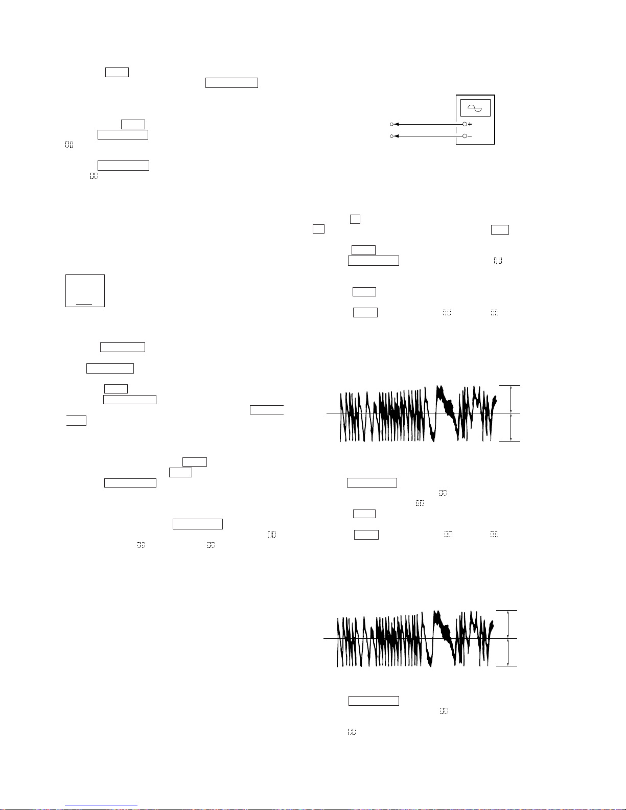
7-11. TRA VERSE ADJUSTMENT
Connection :
Adjusting Procedure :
1. Connect an oscilloscope to CN110 pin 3 (TE) and CN110 pin
1 (VC) of the BD board.
2. Load a disc (any available on the market). (Refer to Note 1.)
3. Press the p button and display the “MD”, and then press the
p button and display the “MD”, and then press the ) button
and move the optical pick-up outside the pit.
4. Rotate the AMS dial and display “EF MO ADJUS” (C11).
5. Press the ENTER/YES button and display “EFB =
MO-R”.
(Laser power READ power/Focus servo ON/tracking servo OFF/
spindle (S) servo ON)
6. Rotate the AMS dial so that the waveform of the oscilloscope
becomes the specified value.
(When the AMS dial is rotated, the of “EFB= ” changes
and the waveform changes.) In this adjustment, waveform varies at intervals of approx. 2%. Adjust the waveform so that the
specified value is satisfied as much as possible.
(Read power traverse adjustment)
(Traverse Waveform)
7. Press the ENTER/YES button and save the result of adjustment
to the non-volatile memory (“EFB = SA VE” will be displayed
for a moment. Then “EFB = MO-W” will be displayed).
8. Rotate the AMS dial so that the waveform of the oscilloscope
becomes the specified value.
(When the AMS dial is rotated, the of “EFB- ” changes
and the waveform changes.) In this adjustment, waveform varies at intervals of approx. 2%. Adjust the waveform so that the
specified value is satisfied as much as possible.
(Write power traverse adjustment)
(Traverse W aveform)
9. Press the ENTER/YES button, and save the adjustment results
in the non-volatile memory. (“EFB =
SA VE” will be displayed
for a moment.)
10. “EFB = MO-P”. will be displayed.
The optical pick-up moves to the pit area automatically and
servo is imposed.
V : 0.5 V/div
H : 10 ms/div
Input : DC mod
e
Oscilloscope
BD board
CN110 pin
3
(TE)
CN110 pin
1
(VC)
VC
A
B
Specification A = B
VC
A
B
Specification A = B
Page 33
– 33 –
11. Rotate the AMS dial until the waveform of the oscilloscope
moves closer to the specified value.
In this adjustment, waveform varies at intervals of approx. 2%.
Adjust the waveform so that the specified value is satisfied as
much as possible.
(Traverse Waveform)
12. Press the ENTER/YES button, and save the adjustment results
in the non-volatile memory. (“EFB =
SAVE” will be displayed for a moment.)
Next “EF MO ADJUST” is displayed. The disc stops rotating
automatically.
13. Press the §EJECT (MD) button and remove the disc.
14. Load the check disc (MD) TDYS-1.
15. Roteto AMS dial and display “EF CD ADJUST”.
16. Press the ENTER/YES button and display “EFB = CD”.
Servo is imposed automatically.
17. Rotate the AMS dial so that the waveform of the oscilloscope
moves closer to the specified value.
In this adjustment, waveform varies at intervals of approx. 2%.
Adjust the waveform so that the specified value is satisfied as
much as possible.
(Traverse Waveform)
18. Press the ENTER/YES button, display “EFB =
SAVE” for
a moment and save the adjustment results in the non-volatile
memory.
Next “EF CD ADJUST” will be displayed.
19. Press the §EJECT (MD) button and remove the check disc
(MD) TDYS-1.
Note 1 : MO reading data will be erased during if a recorded disc is
used in this adjustment.
Note 2 : If the traverse waveform is not clear, connect the oscillo-
scope as shown in the following figure so that it can be
seen more clearly.
7-12. FOCUS BIAS ADJUSTMENT
Adjusting Procedure :
1. Load a test disk (MDW-74/AU-1).
2. Rotate the AMS dial and display “CPLAY MODE”.
3. Press the ENTERYES button and display “CPLAY MID”.
4. Press the MENU/NO button when “C1 = AD = ” is
displayed.
5. Rotate the AMS dial and display “FBIAS ADJUS”.
6. Press the ENTER/YES button and display “ / a = ”.
The first four digits indicate the C1 error rate, the two digits
after [/] indicate ADER, and the 2 digits after [a =] indicate the
focus bias value.
7. Rotate the AMS dial in the clockwise direction and find the
focus bias value at which the C1 error rate becomes about 200
(Refer to Note 2).
8. Press the ENTER/YES button and display “ / b = ”.
9. Rotate the AMS dial in the counterclockwise direction and find
the focus bias value at which the C1 error rate becomes about
200.
10. Press the ENTER/YES button and display “ / c = ”.
11. Check that the C1 error rate is below 50 and ADER is 00. Then
press the ENTER/YES button.
12. If the “( )” in “ - - ( )” is above 20, press the EN-
TER/YES button.
If below 20, press the MENU/NO button and repeat the adjustment from step 2.
13. Press the §EJECT (MD) button to remove the test disc.
Note 1 : The relation between the C1 error and focus bias is as
shown in the following figure. Find points a and b in the
following figure using the above adjustment. The focal
point position C is automatically calculated from points a
and b.
Note 2 : As the C1 error rate changes, perform the adjustment us-
ing the average vale.
VC
A
B
Specification A = B
VC
A
B
Specification A = B
330 k
Ω
Oscilloscop
e
10pF
BD board
CN110 pin
3
(TE)
CN110 pin
1
(VC)
C1 error
about
200
b
c a Focus bias value
(F. BIAS)
Page 34

– 34 –
7-13. ERROR RATE CHECK
7-13-1. CD Error Rate Check
Checking Procedure :
1. Load a check disc (MD) TDYS-1.
2. Rotate the AMS dial and display “CPLAY MODE”.
3. Press the ENTER/YES button twice and display “CPLA Y MID”.
4. The display changes to “C1 = AD = ”.
5. Check that the C1 error rate is below 20.
6. Press the MENU/NO button, stop playback, press the §EJECT
(MD) button, and remove the test disc.
7-13-2. MO Error Rate Check
Checking Procedure :
1. Load a test disc (MDW-74/AU-1).
2. Rotate the AMS dial and display “CPLAY MODE”.
3. Press the ENTER/YES button and display “CPLAY MID”.
4. The display changes to “C1 = AD = ”.
5. If the C1 error rate is below 50, check that ADER is 00.
6. Press the MENU/NO button, stop playback, press the §EJECT
(MD) button, and remove the test disc.
7-14. FOCUS BIAS CHECK
Change the focus bias and check the focus tolerance amount.
Checking Procedure :
1. Load a test disc (MDW-74/AU-1).
2. Rotate the AMS dial and display “CPLAY MODE”.
3. Press the ENTER/YES button twice and display “CPLA Y MID”.
4. Press the MENU/NO button when “C1 = AD = ” is
displayed.
5. Rotate the AMS dial and display “FBIAS CHECK”.
6. Press the ENTER/YES button and display “ / c = ”.
The first four digits indicate the C1 error rate, the two digits
after “/” indicate ADER, and the 2 digits after “c =” indicate the
focus bias value.
Check that the C1 error is below 50 and ADER is below 2.
7. Press the ENTER/YES button and display “ / b = ”.
Check that the C1 error is below 220 and ADER is below 2.
8. Press the ENTER/YES button and display “ / a = ”.
Check that the C1 error is below 220 and ADER is below 2.
9. Press the MENU/NO button, next press the §EJECT (MD)
button, and remove the continuously recorded disc.
Note 1 : If the C1 error and ADER are above other than the speci-
fied value at points a (step 8. in the above) or b (step 7. in
the above), the focus bias adjustment may not have been
carried out properly. Adjust perform the beginning again.
7-15. AUTO GAIN CONTROL OUTPUT LEVEL
ADJUSTMENT
Be sure to perform this adjustment when the pickup is replaced.
If the adjustment results becomes “Adjust NG!”, the pickup may be
faulty or the servo system circuits may be abnormal.
7-15-1. CD Auto Gain Control Output Level Adjustment
Adjusting Procedure :
1. Insert the check disc (MD) TDYS-1.
2. Rotate the AMS dial to display “AG Set (CD)”.
3. When the ENTER/YES button is pressed, the adjustment will
be performed automatically.
“Complete!!” will then be displayed momentarily when the value
is recorded in the non-volatile memory, after which the display
changes to “AG Set (CD)”.
4. Press the §EJECT (MD) button to remove the disc.
7-15-2. MO Auto Gain Control Output Level Adjustment
Adjusting Procedure :
1. Insert the reference disc (MDW-74/AU-1) for recording.
2. Rotate the AMS dial to display “AG Set (MO)”.
3. When the ENTER/YES button is pressed, the adjustment will
be performed automatically.
“Complete!!” will then be displayed momentarily when the value
is recorded in the non-volatile memory, after which the display
changes to “AG Set (MO)”.
4. Press the §EJECT (MD) button to remove the disc.
Page 35
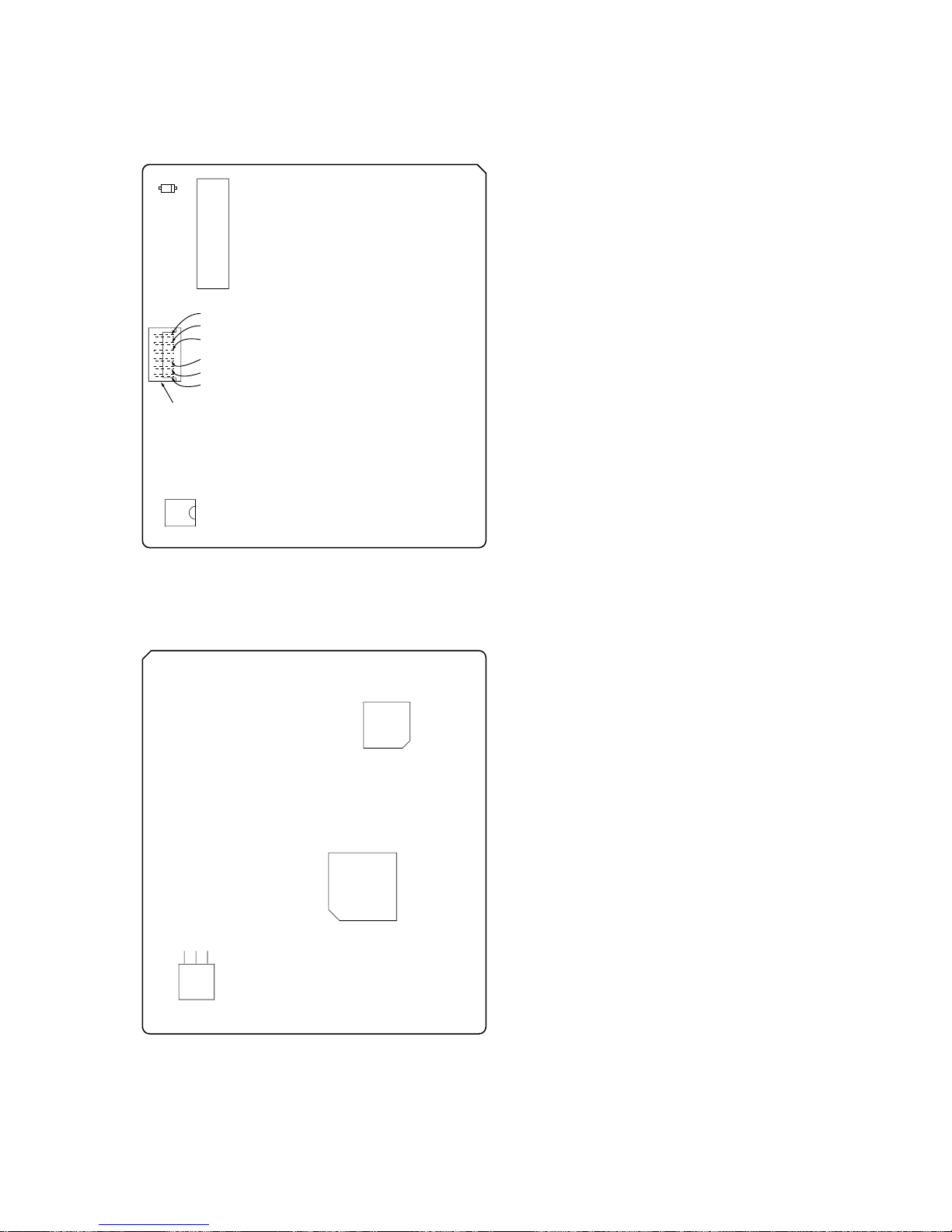
– 35 –
NOTE:It is useful to use the jig. for checking the waveform. (Refer
to Servicing Note on page 9.)
7-16. ADJUSTING POINTS AND CONNECTING POINTS
[BD BOARD] (SIDE A)
[BD BOARD] (SIDE B)
CN110
NOTE
D101
I+3V
IOP
TE
VC
GND
IC171
IC121
IC101
IC192
CN101
RF
Page 36
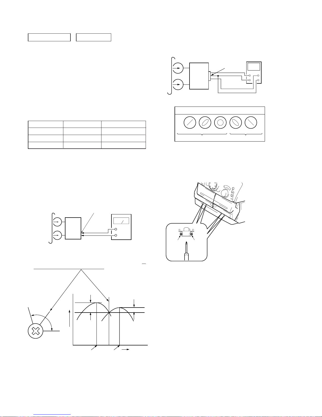
– 36 –
4. After the adjustments, apply suitable locking compound to the
parts adjusted.
Adjustment Location: Playback Head (Deck A)
Record/Playback/Erase Head (Deck B)
3. Mode: Playback
test tape
P-4-A100
(10kHz, –10dB)
oscilloscope
set
Waveform of oscilloscope
in phase 45
°
90
°
135
°
180
°
good
wrong
VIDEO (AUDIO) OUT
Reverse Foward
Record/Playback Head Azimuth Adjustment
(Deck A, Deck B)
Note: Perform this adjustments for both decks.
Procedure:
1. Mode : Playback
Signal
Used for
Tape
DECK SECTION 0 dB=0.775V
1. Demagnetize the record/playback head with a head damagnetizer .
2. Do not use a magnetized screwdriver for the adjustments.
3. After the adjustments, apply suitable locking compound to the
parts adjusted.
4. The adjustments should be performed with the rated power supply voltage unless otherwise noted.
5. The adjustments should be performed in the order given in this
service manual. (As a general rule, playback circuit adjustment
should be completed before performing recording circuit adjustment.)
6. The adjustments should be performed for both L-CH and R-CH.
7. Switches and controls should be set as follows unless otherwise
specified.
P-4-A100
WS-48B
P-4-L300
10 kHz, –10 dB
3 kHz, 0 dB
315 Hz, 0 dB
Azimuth Adjustment
Tape Speed Adjustment
Level Adjustment
2. Turn the adjustment screw and check output peaks. If the peaks
do not match for L-CH and R-CH, turn the adjustment screw so
that outputs match within 1 dB of peak.
test tape
P-4-A100
(10kHz, –10dB)
VIDEO (AUDIO) OUT
level meter
set
+
–
L-CH
peak
R-CH
peak
screw
position
output
level
within
1 dB
L-CH
peak
R-CH
peak
screw
position
within 1dB
Page 37
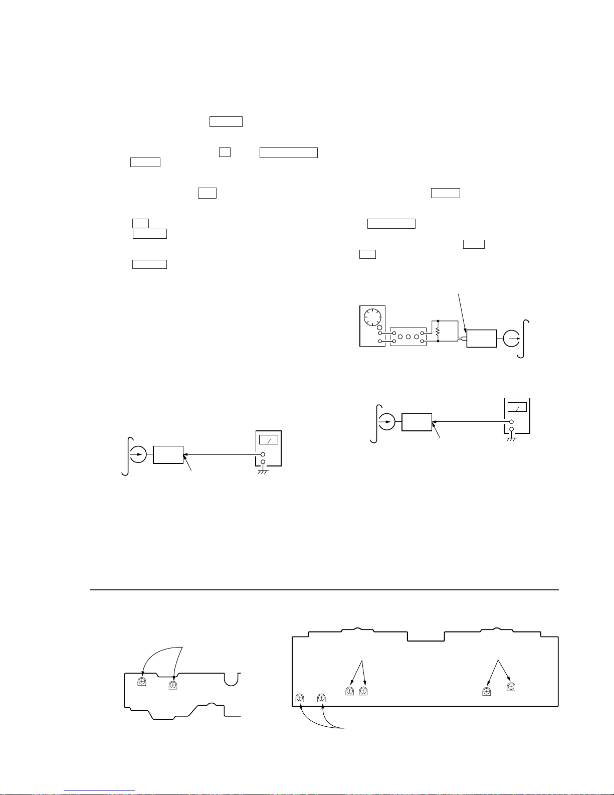
– 37 –
Tape Speed Adjustment (Deck A)
Note: Set the test mode using the following method and begin tape
speed adjustment.
In the test mode, the speed will switch to double speed or
normal speed each time the HI DUB button is pressed.
Procedure:
With the power turned ON, press the p button, ENTER/NEXT
button, and DISC 3 button simultaneously.
(The “CD TYPE INDICA T OR” on the fluorescent display tube will
blink while in the test mode.)
To exit the test mode, press the 1/u button.
1. Insert the WS-48B into deck B.
2. Press the ( button of deck B.
3. Press the HI DUB button and play the tape at double speed.
4. Adjust RV1001 of the LEAF SW board so that the reading of
the frequency counter becomes 6000 ± 180 Hz.
5. Press the HI DUB button and play the tape at normal speed.
6. Adjust RV1002 of the LEAF SW board so that the reading of
the frequency counter becomes 3000 ± 90 Hz.
Adjustment Location: LEAF SW board
Sample Value of Wow and flutter
W.RMS (JIS) less than 0.3%
(test tape: WS-48B)
Playback Level Adjustment (Deck A, Deck B)
Procedure:
Mode: Playback
Deck A is RV311 (L-CH) and RV411 (R-CH), deck B is RV301
(L-CH) and RV401 (R-CH)
so that adjustment within the following adjustment level.
Adjustment level:
CN301 playback level: 301.5 to 338.3 mV (–8.2 to –7.2 dB)
level difference between the channels: within ± 0.5 dB
Adjustment Location: AUDIO board
Adjustment Location
[LEAF SW BOARD]
test tape
P-4-L300
(315Hz, 0dB)
level meter
set
VIDEO (AUDIO) OUT
RV1002 RV1001
RV1002(Normal Speed
)
RV1001(High Speed)
Record Bias Adjustment (Deck B)
Procedure:
INTRODUCTION
When set to the test mode performed in Tape Speed Adjustment, when the tape is rewound after recording, the “REC memory
mode” which rewinds only the recorded portion and playback is
set.
This “REC memory mode” is convenient for performing this adjustment. During recording, the input signal FUNCTION will automatically switch to VIDEO.
(After recording, press the – 0 button without stopping will
return to the position where recording was started.)
1. Press FUNCTION button to select VIDEO. (This step is not
necessary if the above test mode has already been set.)
2. Insert a tape into deck B, press the REC button, and then press
the ( button to start recording.
3. Mode: Record
5. Confirm playback the signal recorded in step 2 become adjustment level as follows.
If these levels do not adjustment level, adjust the RV341 (LCH) and RV441 (R-CH) on the AUDIO board to repeat steps 3
and 4.
Adjustment level: The playback output of 10 kHz level difference
against 315 Hz reference should be ± 1.0 dB.
Adjustment Location: AUDIO board
4. Mode: Playback
recorded
position
level meter
set
VIDEO (AUDIO) OUT
AF OSC
VIDEO (AUDIO) IN
1) 315 Hz
2) 10 kHz
blank tape
CS-123
set
attenuator
600
Ω
} 50 mV (–23.8 dB)
Adjustment Location:
[AUDIO BOARD] (Conductor Side)
RV441 RV341
RV301(Lch),RV401(Rch)
Playback Level (Deck B)
RV301 RV401
RV341(Lch),RV441(Rch)
Record Bias
RV311(Lch),RV411(Rch)
Playback Level (Deck A)
RV311
RV411
Page 38
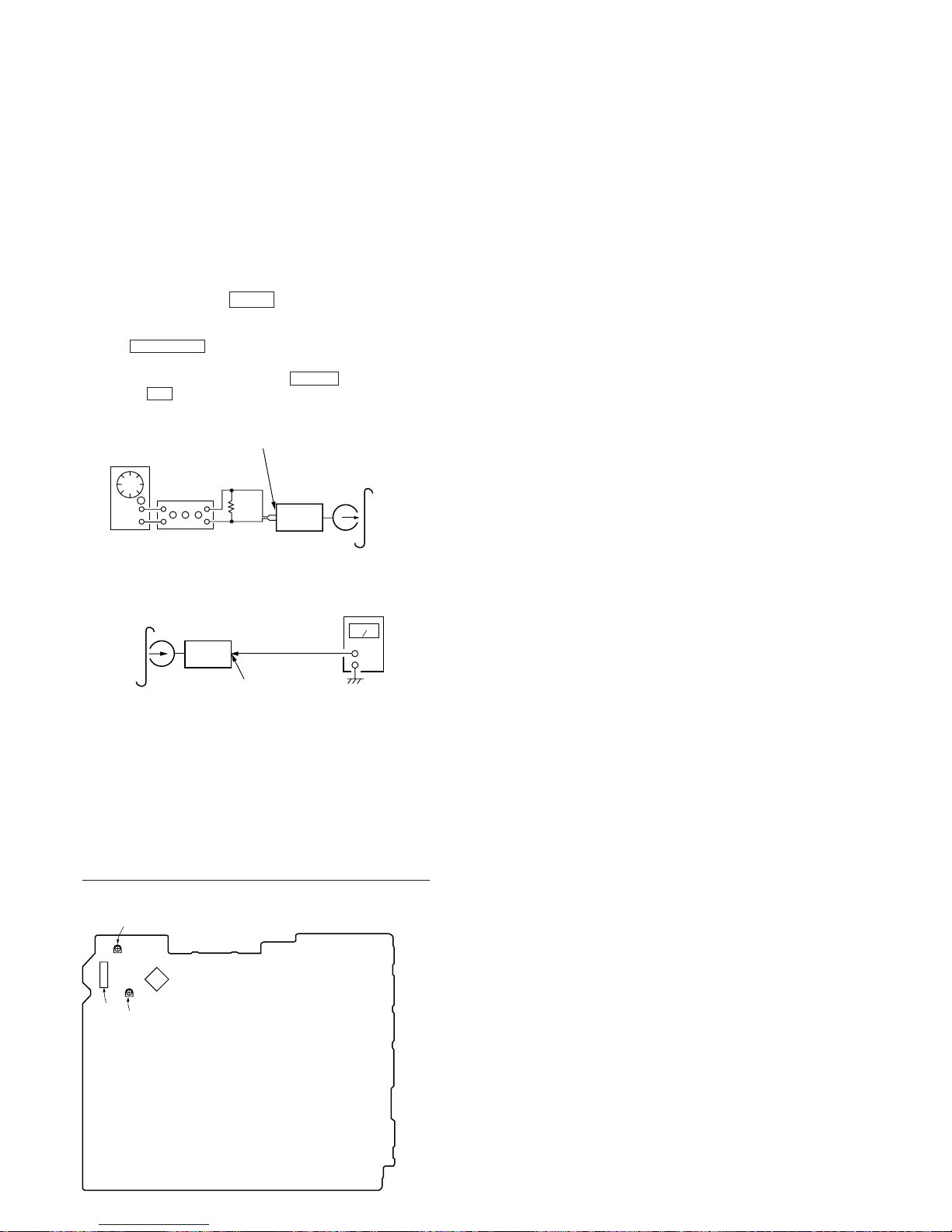
– 38 –
Record Level Adjustment (Deck B)
Procedure:
INTRODUCTION
When set to the test mode performed in Tape Speed Adjustment, when the tape is rewound after recording, the “REC memory
mode” which rewinds only the recorded portion and playback is
set.
This “REC memory mode” is convenient for performing this adjustment. During recording, the input signal FUNCTION will automatically switch to VIDEO.
(After recording, press the – 0 button without stopping will
return to the position where recording was started.)
1. Press FUNCTION button to select VIDEO 1. (This step is not
necessary if the above test mode has already been set.)
2. Insert a tape into deck B, press the r REC button, and then
press the ( button to start recording.
3. Mode: Record
4. Mode: Playback
5. Confirm playback the signal recorded in step 2 become adjustment level as follows.
If these levels do not adjustment level, adjust the RV301 (LCH) and RV351 (R-CH) on the MAIN board to repeat steps 3
and 4.
Adjustment level:
CN403 playback level: 47.2 to 53.0 mV (–24.3 to –23.3 dB)
Adjustment Location: MAIN board
[MAIN BOARD] (Conductor Side)
AF OSC
VIDEO (AUDIO) IN
315Hz 50 mV (–23.8 dB)
blank tape
CS-123
set
attenuator
600
Ω
recorded
position
level meter
set
VIDEO (AUDIO) OUT
IC301
Record Level (L CH)
RV301
CN303
RV351
Record Level (R CH)
56
43
42
29
28
15
14
1
Page 39
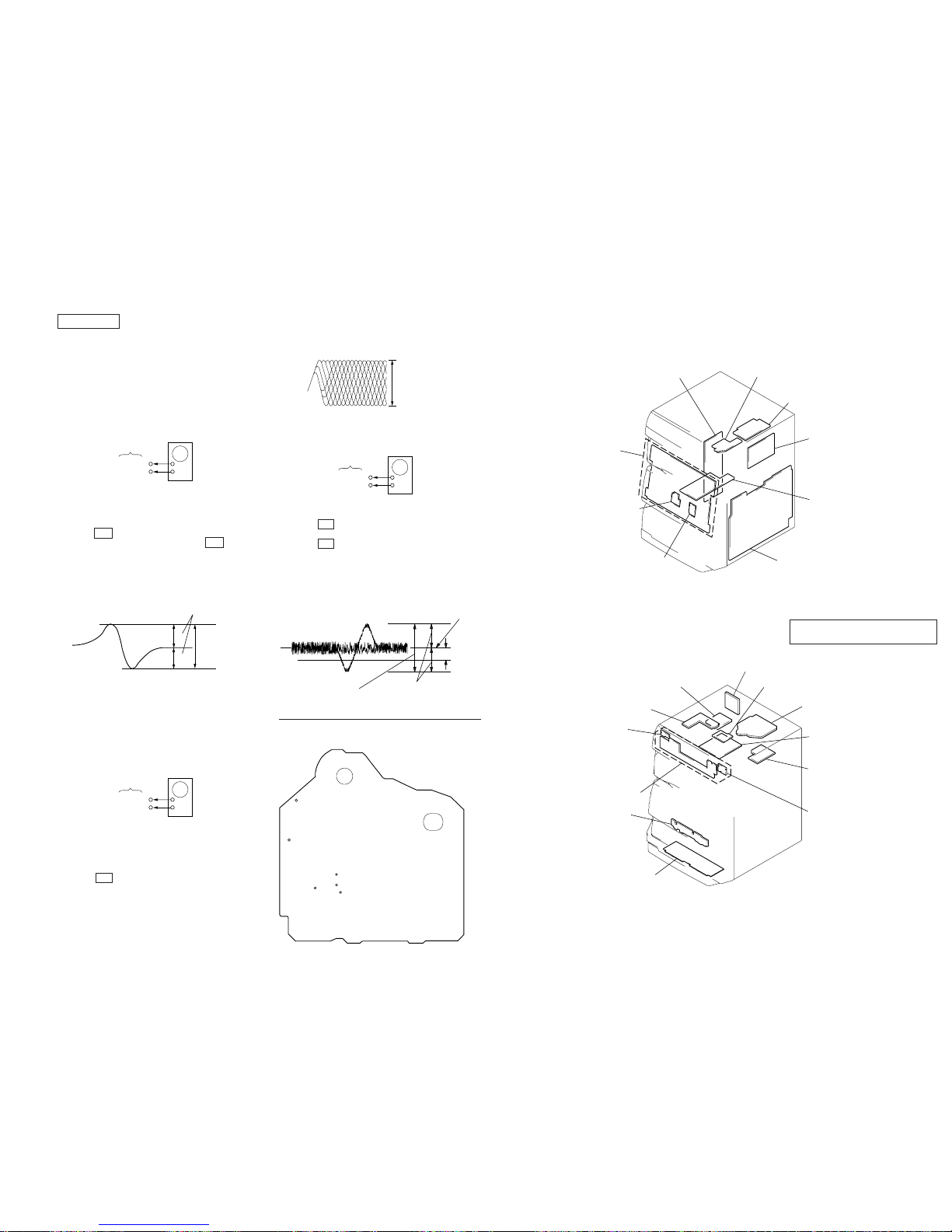
HCD-MDX10
– 39 –
SECTION 8
DIAGRAMS
8-1. CIRCUIT BOARDS LOCATION
– 40 –
MAIN board
DISPLAY board
JOG board
VOL board
ENCAPSULATED COMPONENT
(US,CND,AR,KR,SP,MY,HK,AUS)
TUNER unit
(AEP,UK,E,G,CIS)
SECONDARY board
STANDBY board
MD DIGITAL board
MD LINK board
SENSOR board
CONNECTOR board
BD (CD) board
BD (MD) board
MOTOR (SLIDE) board
MD LINK SW board
MOTOR (TURN) board
SW board
POWER SW board
CD PANEL board
AUDIO board
LEAF SW board
CD SECTION
Note:
1. CD Block is basically constructed to operate without adjustment.
Therefore, check each item in order given.
2. Use YEDS-18 disc (3-702-101-01) unless otherwise indicated.
3. Use an oscilloscope with more than 10MΩ impedance.
4. Clean the object lens by an applicator with neutral detergent when
the signal level is low than specified value with the following
checks.
S Curve Check
Procedure :
1. Connect the oscilloscope to test points TP (FE) and TP (VC).
2. Connect TP (FEI) and GND, and TP (AGCCON) and GND of
the BD board with lead wires.
3. Press the 1/u button to turn the set ON.
4. With the disc (YEDS-18) loaded, press the ^ button and
perform focus search. (Focus search will be performed in the
same way even while the disc table is pushed in and out.)
5. Check the symmetry and peak to peak level of the oscilloscope
waveform (S curve) at this time.
S-curve waveform
6. After check, remove the lead wire connected in step 2.
Note: • Try to measure several times to make sure than the ratio of
A : B or B : A is more than 10 : 7.
• Take sweep time as long as possible and light up the brightness to obtain best waveform.
Adjustment Location : BD (CD) board
RF Level Check
Procedure :
1. Connect oscilloscope to test point TP (RF) and TP (VC) on BD
board.
2. Connect TP (AGCCON) and GND of the BD board with lead
wires.
3. Press the 1/u button to turn the set ON.
4. Put disc (YEDS-18) in and playback 5track.
5. Confirm that oscilloscope waveform is clear and check RF signal level is correct or not.
6. After check, remove the lead wire connected in step 2.
oscilloscope
BD board
TP (FE)
TP (VC)
+
–
symmetry
A
B
Within 4
±
1 Vp-p
oscilloscope
BD board
TP (RF)
TP (VC)
+
–
VOLT/DIV : 200mV
TIME/DIV : 500ns
level : 1.45 ± 0.3 Vp-p
0V
Center of the waveform
B
Symmetry
A (DC voitage)
level : 1.3
±
0.6 Vp-p
oscilloscope
BD board
TP (TE)
TP (VC)
+
–
Note: Clear RF signal waveform means that the shape “◊” can be
clearly distinguished at the center of the waveform.
RF signal waveform
Adjustment Location : BD (CD) board
E-F Balance (1 Track Jump) check
Procedure:
1. Connect oscilloscope to test point TP (TE) on BD board.
2. Press the 1/u button to turn the unit ON.
3. Put disc (YEDS-18) in to play the number five track.
4. Press the ^ button.
5. Check the level B of the oscilloscope's waveform and the A (DC
voltage) of the center of the Traverse waveform.
Confirm the following:
• A/B x 100 = less then ± 22 (%)
• B = 1.3 ± 0.6 Vp-p
1 track jump waveform
Adjustment Location : BD (CD) board
Adjustment Location :
[ BD (CD) BOARD ] — SIDE A —
TP
(VC)
TP
(RF)
TP
(TE)
TP
(FE1)
TP (FE)
TP
(AGCCON)
• Abbreviation
CND : Canadian model
G : German model
SP : Singapore model
MY : Malaysia model
HK : Hong Kong model
AR : Argentine model
KR : Korea model
AUS : Australian model
ENCAPSULATED COMPONENT/TUNER
unit is supplied as the assembled block.
Page 40
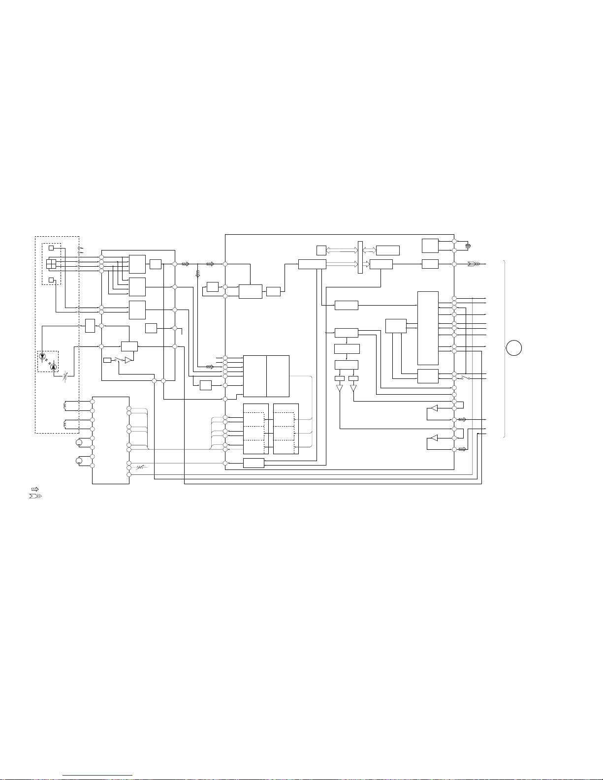
HCD-MDX10
8-2. BLOCK DIAGRAMS
– BD (CD) SECTION –
– 41 –
– 42 –
E
F
ABC
D
A
C
RF
FF
TE
D
B
E
F
LD
PD
VCC
VC
RF
SUMMING
AMP
FOCUS
ERROR
AMP
TRACKING
ERROR
AMP
LD
DRIVE
Q101
VC
BUFFER
INTEGRATOR
RF EQ
AMP
INTEG-
RATOR
DIGITAL
PLL
IC101
DIGITAL SERVO
DIGITAL SIGNAL PROCESSOR
SUBCODE
PROCESSOR
SERIAL IN
INTERFACE
SERVO
AUTO
SEQUENCER
SERVO
INTERFACE
OVER SAMPLING
DIGITAL FILTER
D/A
INTERFACE
DIGITAL
OUT
TIMING
LOGIC
ERROR
CORRECTOR
EFM
DEMODULATION
APCLD/PD
AMP
5
7
8
6
16
14 49
51
13
LDON
VC
22
1521
12
11
10
3
IC103
RF AMP
VC
4
VREF
HOLD SW
REF
IC102
FOCUS/TRACKING COIL DRIVE
SPINDLE/SLED MOTOR DRIVE
11
12
T+
T–
14
13
F+
F–
TRACKING
COIL
FOCUS
COIL
CH2OUTR
CH2OUTF
5
CH2FIN
6
CH2RIN
2
CH1FIN
3
CH1RIN
23
CH3RIN
24
CH3FIN
25
CH4SIN
27
CH4BIN
20
MUTE
CH1OUTF
CH1OUTR
17
18
SD+
SD–
CH3OUTF
CH3OUTR
M
15
16
SP+
SP–
CH4OUTF
CH4OUTR
M
M102
SLED
MOTOR
M101
SPINDLE
MOTOR
TFDR
TRDR
FFDR
FRDR
SRDR
SFDR
VC
FD
PD
LASER
DIODE
A
C
D
B
E
F
DETECTOR
OPTICAL PICK-UP BLOCK
(KSS-213D/K-NP)
LD
POWER
RF AC
ASY1
48
38
42
43
39
41
40
28
26
29
ASY0
ASYMMETRY
CORRECTION
SFDR
MDP
SRDR
33
32
FRDR
FFDR
31
30
42
TRDR
TFDR
SE
CE
TE
FE
RFDC
CE
VC
SLED
PWM
GENERATOR
FOCUS
PWM
GENERATOR
TRACKING
PWM
GENERATOR
PWM
GENERATOR
SLED
SERVO
FOCUS
SERVO
TRACKING
SERVO
SERVO DSP
DIGITAL
CLV
OPERATIONAL
AMPLIFIER
ANALOG
SWITCH
A/D
CONVERTER
16K
RAM
DATA BUS
3rd ORDER
NOISE SHAPER
PWM PWM
CPU
INTERFACE
2
1
3
SQSO
60
D OUT
67
STAO
66
XTA1
8
SENS
20
SCOR
14
XLON
XRST
SQCK
5
DATA
6
XLAT
7
CLOK
9
SCLK
27
SSTP
79
RMUT
80
LMUT
70
LMUT
71
AIN1
72
LOUT1
77
LOUT2
76
AIN2
75
LOUT2
L OUT
R OUT
HOLD
+5V
SQCK
SCOR
CLOK
XLT
DATA
SENS
SQSO
XRST
DOUT
X101
16.9344MHz
G
MAIN
SECTION
(Page 47)
09
S101
LIMIT SW
• SIGNAL PATH
: CD
: PB (Digital out)
Page 41
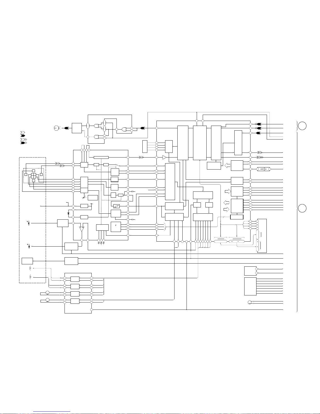
HCD-MDX10
– 43 – – 44 –
– BD (MD) SECTION (1) –
HR901
OVER WRITE
HEAD
HEAD
DRIVE
Q181,182
3
6
1
2
FILTER
PCO
FILI
FILO
CLTV
PLL
EFM,
ACIRC,
ENCODER/
DECODER
RF AGC & EQ
AGCI
RFO
MORFI
MORFO
RF AMP
1
2
BPF
P-P
AT
AMP
BPF
ADAGC
VC
ANALOG
MUX
27
16
17
18
SERIAL
PARALLEL
DECODER
VICONV
20
2522 23
4
5
6
7
8
9
IV AMP
IV AMP
E-F
BALANCE
14
15
3
VCC
VC
D101
12
11
10
LASER ON
SW
Q101
PD
APC
Q162,163
HF
MODULE
HF MODULE
SW
IC103,Q102-104
TRACKING
COIL
FOCUS
COIL
10
12
DRIVER
21
DRIVER
23
27
DRIVER
25
6
8
DRIVER
16
TFDR
PSB
XRST
SLED/SPINDLE MOTOR DRIVE
FOCUS/TRACKING COIL DRIVE
IC152
09
M
M
M102
SLED MOTOR
M101
SPINDLE MOTOR
DETECTOR
F
IJ
C
D
B
A
E
VC
LD
PD
ILCC
15 14
ATRAC
ENCODER/
DECODER
SAMPLING
RATE
CONVERTER
DTRF
CKRF
XLRF
FOCNT
79
82
81
80
93
94
95 10
SPRD
SPFD
FG IN
XRST
SPINDLE
SERVO
ADIP
DEMODULATOR/
DECODER
78
ADFG
A/D
CONVERTER
SERVO
DSP
APC
PWM
GENERATOR
21
26
25
20
SUBCODE
PROCESSOR
11
12
MONITOR
CONTROL
4
3
2
1
3
CPU
I/F
AUTO
SEQUENCER
16
27
28
7
5
6
8
9
7
3
512FS
M
M103
LOADING MOTOR
BCK
LRCK
BUFFER IC123
DRAM
IC124
SQSY
DQSY
MNT3
MNT2
MNT1
MNT0
SENS
SRDT
SCLK
SWDT
XLAT
DIN1
19
DIN0
ADDT
DADT
DOUT
91928586898883
13
RECP
APCREF
FFDR
FRDR
TFDR
TRDR
SFDR
SRDR
FOCNT
XLAT
SCLK
SWDT
CSLED
SE
TE
26
28
32
30
ADFG
ADIN
ADFM
29
31
34 66
68
75
74
FE
VC
TE
SE
33 67
36
37
35
64
63
65
AUX
BOTM
PEAK
ABCD
FE
AUX1
BOTM
PEAK
ABCD
38
RF
57
RFI
59
60
61
62
ABCD
AMP
FOCUS
ERROR
AMP
I
J
A
B
C
D
E
F
VC
CVB
TEMP
AMP
TEMPR
TEMPI
APC
APCREF
EQADJ
3TADJ
WBLADJ
TRACKING
ERROR
AMP
OPTICAL PICK-UP BLOCK
(KMS-260A/K1NP)
48 47 46 40
RF AMP
IC101
EFMO
TX
XINIT
CLOCK
GENERATOR
14
15
18
19
29
30
3
4
SPFD
SPRD
SFDR
SRDR
TRDR
FRDR
FFDR
OVER WRITE HEAD DRIVE
IC181
OSCI
XBCK
LRCK
VC
VC
PEAK
&
BOTTOM
TRK–
TRK+
FSC+
FSC–
SLED+
SLED–
SPDL+
SPDL–
DIGITAL SERVO SIGNAL PROCESSOR, DIGITAL SIGNAL PROCESSOR
EFM/ACIRC ENCODER/DECODER, SHOCK-PROOF MEMORY CONTROLLER,
ATRAC ENCODER/DECODER
IC121
DIN0
DIN1
SCTX
XINT
ADDT
DADT
DOUT
(NON CONNECT)
SQSY
DQSY
MNT3
MNT2
MNT1
MNT0
SENS
SRDT
SCLK
SWDT
XLAT CH
LDON
WRPWR
MOD
6
5
SDA
SDA
SCLSCL
LIMIT-IN
REFLECT
PROTECT
CHACK IN SW
PACK OUT SW
PLAY-P SW
REC P SW
EEP ROM
IC171
LOAD-IN
LOAD-OUT
DIG-RST
DETECT SW
S101, S102,
S601-604
100
49 • 48 • 50 • 51
34 31 • 36 40 • 45
D0 D3 A00 A09
47463
4
17
16
1
2
18
19
6
9
11
15
5
XWE
XRAS
XCAS
XOE
DQ1
DQ4
•
•
•
•
A0
A9
44
43
20
XWE
XRAS
XCAS
XOE
•
SHOCK
RESISTANT
MEMORY
CONTROLLER
8
•
11
10
•
13
9
•
12
4
5
DIGITAL
AUDIO
I/F
BD (MD)
SECTION
(Page 45)
• R-ch is omitted.
• Signal path
: PB
: REC
: PB (Digital out)
: REC (Digital in)
A
MAIN
SECTION
(Page 48)
B
Page 42
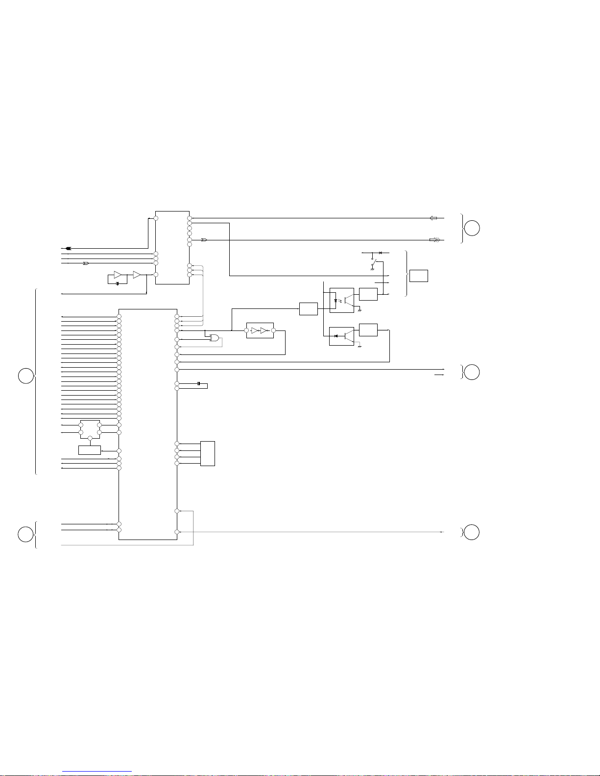
HCD-MDX10
– 45 –
– 46 –
– BD (MD) SECTION (2) –
27
73
72
17
16
18
12
19
4
2
26
14
13
24
15
80
79
75
78
82
81
35
37
36
58
63
66
53
51
59
57
74
60
54
65
67
88
56
55
77
87
69
22
21
19
15
13
12
94
97
18
ADDT
BCK
LRCK
DADT
512FS
SCTX
XINT
SQSY
DQSY
MNT3
MNT2
MNT1
MNT0
SENS
SRDT
SCLK
SWDT
XLATCH
LIMIT-IN
REFLECT
PROTECT
CHACKIN SW
PACK-OUT SW
PB P SW
REC-P SW
LD ON
WRPWR
MOD
LOAD-IN
LOAD OUT
SDA
SCL
DIG-RST
IIC CLK
IIC DATA
P.DOWN
SCTX
L3-CLK
L3-DATA
L3-MODE
WM SYNC
X OUT
100
WM IN
2
WM CLK
LEVEL-L
1
3
WM OUT
WM INV
X IN
S.RST
KEY0
KEY2
93KEY3
P.DOWN
XINT
SQSY
DQSY
MNT3(S-LOCK)
MNT2(X-BUSY)
MNT1(SHOCK)
MNT0(F-OK)
SENS
SRDT
SCLK
SWDT
XLATCH
LIMIT-IN
REFLECT
PROTECT
CHACKIN
PACK-OUT
PB-P
REC-P
LDON
WR PWR
MOD
LD-IN
LD OUT
SDA
SCL
DIG-RST
29
IIC CLK
30
IIC DATA
810
911
95KEY1
LD-LOW
10
9
2
4
6
X701
10MHz
LOADING SW
Q350
A/D,D/A CONVERTER
IC201
IC202 IC202
SYSTEM CONTROL
IC316
DATAO VINL1
VINR1
8
VINR2
6
VINL2
R-CH
R-CH
R-CH
VOUTL
VOUTR
L3MODE
L3CLK
L3DATA
BCK
WS
DATAI
SYSCLK
X201
22MHz
BD (MD)
SECTION (1)
(Page 44)
LOADING
MOTER
DRIVE
IC153
MATRIX
SWITCH
09
A
MAIN
SECTION
(Page 48)
D
45
3 6
WM DET
Q201
BUFFER
Q205
MD
WALKMAN
LINK
BUFFER
Q204
IC405
WM DET
WM VCC
Q202
WM Lch
CN401
WM VCC
WM Rch
DATA
IC403
8
6
5
IC405
WM DET
+ 3.3V
23
MD IN1 L
(AD IN L)
DATA OUT L
LEVEL L
LEVEL R
RESET
MAIN SECTION
(Page 47)
C
DISPLAY SECTION
(Page 51)
E
MAIN POWER/
SUB POWER SECTION
(Page 53)
F
IC2000
IC202
LEVEL SHIFT
1
2
4
Page 43
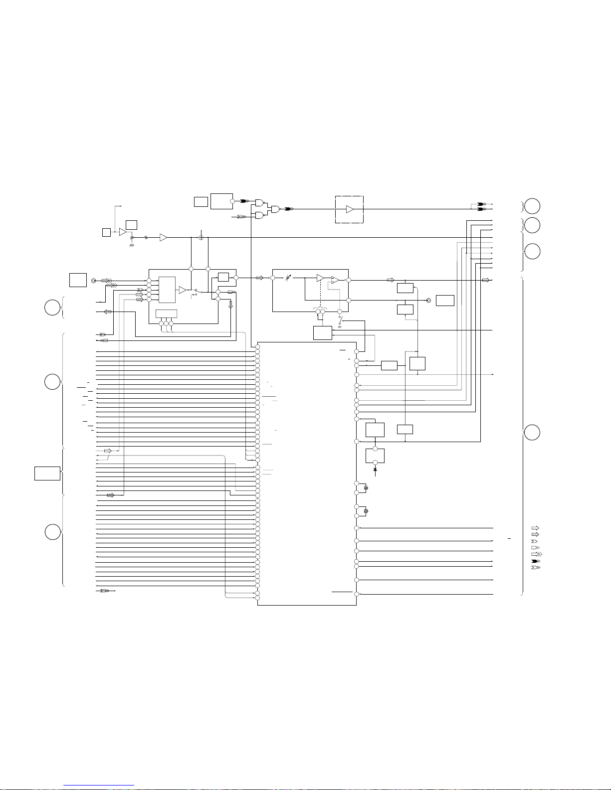
HCD-MDX10
– 47 –
– MAIN SECTION –
– 48 –
SW MUTE
Q191
DBFB
SPEANA
IIC DATA
D IN 1
D IN 0
IIC CLK
P. DOWN
IIC DATA
IIC CLK
RESET
FRONT
F RELAY
CD POWER
STK MUTE
34
100
90
89
88
87
86
84
83
D503
RESET
SWITCH
Q501
RESET
IC502
+5.6V (STBY)
13
15
X613
16MHz
12
22
10
11
09
5
1
CD POWER
STK MUTE
48
54
50
51
52
49
ST DIN
STEREO
TUNED
ST CE
ST CLK
ST MUTE
ST DOUT
TC RELAY
D IN SEL
TC MUTE
A PLAY SW
B PLAY SW
65
19
61
57
56
59
37
35
60
33
32
58
TBL L
TBL R
SCOR
T SENS
HOLD
SENS
XRST
CD CLK
CD DATA
DISC SENS
SQ CLK
SQ DATA
XLT
7
6
DBFB H/L
LINE MUTE
30
29
IIC DATA
IIC CLK
RESET
AC CUT
(CHECK)
X-OUT
X-IN
XC-IN
XC-OUT
X601
32.768KHz
MASTER CONTROL
IC501
3
F RELAY
WAKE UP
ST-BY LED/CLOCK OUT
RDS DATA
RDS INT
82
81
80
79
76
73
72
PB A/B
R/PB PASS
BIAS
REC MUTE
NR ON/OFF
A SHUT
B SHUT
B HALF
A HALF
EQ H//N
CAP M H/L
CAPM CNT1
CAPM CNT2
CAPM CNT1
CAPM CNT2
A TRG
B TRG
AMS IN
493-LAT
493-DATA
493-CLK
RELAY
ST L
RDS INT
RDS DATA
ST-DOUT
ST-CLK
ST-DIN
STEREO
TUNED
ST CE
ST-MUTE
L CH
TBL. L
TBL. R
SCOR
TRAY SENS
HOLD
SENS
X RST
CD CLK
CD DATA
DISC SENS
SQ CLK
SQ DATA
X LAT
H
DECK
SECTION
G
CD
SECTION
A SHUT
PB L
REC L
BIAS ON/OFF
B SHUT
RM ON/OFF
LM ON/OFF
REC/PB/PASS
B HALF/REC A/REC B
A HALF
A PLAY
B PLAY
PB A / B
NORM/HIGH
NR ON/OFF
CAP M H/L
A TRG
B TRG
MS OUT
38
3
1
2
(Page 50)
(Page 42)
C
BD (MD)
SECTION (2)
(Page 46)
POWER ON/OFF
2
POWER
J
POWER
SECTION
53
55
• R CH: Same as L ch
• SIGNAL PATH
: FM
: CD
: PB
: REC
: VIDEO/MD
: REC (Digital in)
: REC (Digital out)
VIDEO/IN
(AUDIO)
L
71
70
69
68
67
66
OUT OPEN
ENC1
ENC2/DISC-LED
ENC3/UP-SW
LOAD IN
LOAD OUT
OUT-OPEN
ENC-1
ENC-2
ENC-3
LD IN
LD OUT
D OUT
J102
(Page 53)
I
DISPLAY
SECTION
(Page 51)
D
BD (MD)
SECTION (2)
(Page 45)
B
BD (MD)
SECTION (1)
(Page 44)
68
69
66
67
65
1 2 3
230
42
58
57
41
36
38 39
72
TA MUTE
Q113
SUPER
WOOFER
J191
MIC
LEVEL
MIX
MIC
RV712
J711
63
47
21
20
78
77
75
74
85
18
39
DBFB
SWITCH
Q111,112
33 32
R-CH
R-CH
EQ
AMP
SELECT
SWITCH
MICON
INTERFACE
IC712(1/2)
IC712(2/2)
VOLUME
IC101(2/2)
EQ
IC101(1/2)
V
TC
TU
CD
MD
Lch
Lch
37
44
HIGH/LOW FRQ.
Q201
MUTE SW
Q509
MUTE SW
Q508
TIMER LED
26
HP DET
36
FL SW
42
STBY RELAY
43
PROTECTOR ON
27
FL SW ON/OFF
STANDBY RELAY
ON/OFF
PROTECTOR
RY-SW
1
3
WAKE UP
STANDBY LED
TIMER LED
91
ALC
ALC ON/OFF
FM/AM TUNER
TUNER UNIT IS
SUPPLIED AS THE
ASSEMBLED
BLOCK
MIC IN SW
(TO DISPLAY SECTION)
DATA OUT L
MD IN1 L
(AD IN L)
D OUT
OPT IN
D OUT
30
46
BD (MD) SECTION (2)
(DIGITAL)
IC202
1
D IN
2
TA MUTE
SW MUTE
Q192
IC381
SELECT
IC382
DIGITAL
OPTICAL
Page 44
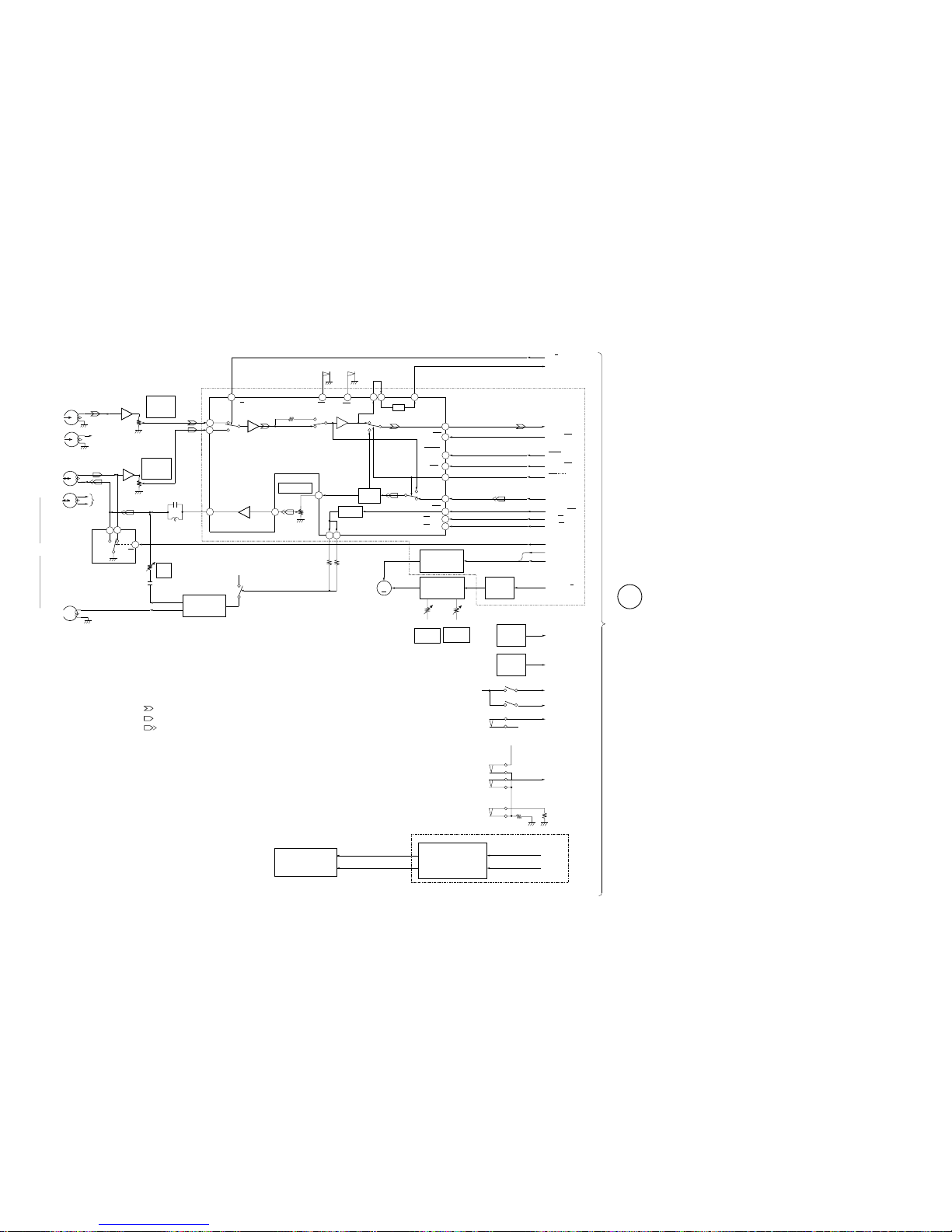
HCD-MDX10
– 49 –
– 50 –
– DECK SECTION –
IC611
R CH
HP101
PB HEAD
(DECK A)
L
R
RV311
PLAYBACK
LEVEL
DECK A
IC601
R CH
L
R
RV301
PLAYBACK
LEVEL
DECK B
3
1
IC602
4
REC/PB
EQOUT
REC BIAS
BIAS OSC
T621, Q621, 622
ERASE HEAD
ERASE BIAS
46
48
B IN
A IN
16
PB-A/B
EQIN
38
36
RV301
REC LEVEL
39
RECOUT
BIAS SW
C
M
70
120
DOLBY
TYPE B
+7.5V
Q623
RIN
44
PB
24
18
20
22
40
25
PB OUT
LM ON/
OFF
BIAS ON/OFF
RM ON/OFF
ALC ON/OFF
PB L
REC L
PB A/B
NORM/HIGH
REC/PB/PASS
BIAS ON/OFF
RM ON/OFF
15
ALC ON/OFF
RELAY
09
H
MAIN
SECTION
LM ON/OFF
NORM/
HIGH
PAS
DOL
P
R
REC/PB HEAD
(DECK B)
X
DOLBY NR
IC301
DOLBY NR
HRPE101
RV341
REC
BIAS
32 33
23
NR ON/
OFF
NR ON/OFF
17
S1004
A CrO
2
S1008
B CrO
2
19
A 120/70
B 120/70
M
CAP MOTOR
CONTROL
Q336-343
SPEED
CONTROL
Q1001
SWITCH
Q335
RV1001
HIGH
SPEED
RV1002
NORMAL
SPEED
M1
CAPSTAN
MOTOR
CAPM CNT2
CAP M H / L
CAPM CNT1
REEL
DETECT
IC1001
A SHUT
B SHUT
REEL
DETECT
IC1002
S1001 (A PLAY)
+5V
S1002 (B PLAY)
A PLAY
B PLAY
A HALF
B HALF/REC A/REC B
S1003
(A HALF)
+5V
+5V
S1005
(REC A)
S1006
(B HALF)
S1009
(REC B)
(Page 47)
• R CH : Same as L ch
• SIGNAL PATH
: PB (DECK A)
: PB (DECK B)
: REC (DECK B)
28
27
26
MS
MS OUT
B TRIG
A TRIG
TRIGGER
MOTOR
CONTROL
Q331-334
A DECK/
B DECK
PLUNGER
• PLUNGER SOLENOID is supplied
as the MECHANICAL BLOCK ASSY.
MAIN SECTION
MAIN SECTION
Page 45
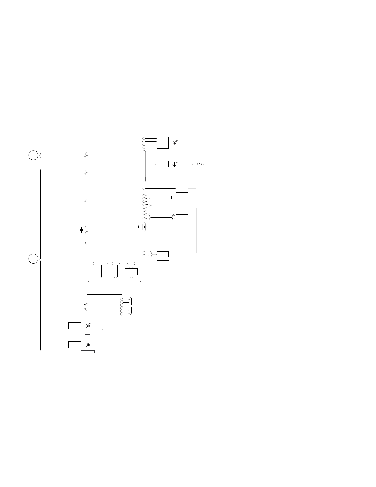
HCD-MDX10
– 51 –
– DISPLAY SECTION –
– 52 –
X601
12.5MHz
MD RECL
MD RECR
28
21
LEVEL L (MD RECL)
RCH
33 - 4652 - 86
FL601
FLUORESCENT INDICATOR TUBE
VF
91
89
XOUT
REC IN
XIN
1720KEY 0
KEY 3
JOG A
JOG B
10
1
SIRCS
L SEL
100
DISPLAY CONTROL
IC601
I2C DATA
I
2
C CLK
97
98
92
RESET
LED
PANEL LED
REMOTE
CONTROL
RECEIVER
IC602
LED
CONTROL
Q603
ROTARY
ENCODER
KEY
MATRIX
+5V (LED)
SEG1-SEG35
GR5-GR18
11
12
VOL A
VOL B
ROTARY
ENCODER
VOLUME
S602
S601
(JOG)
Q601,602
23
22
25
24
S LOW (F01)
BPF1 (F02)
BPF2
BPF3
BPF4
09
MIC IN SW
(FROM MAIN SECTION)
SPEANA
IIC DATA
IIC CLK
RESET
E
BD (MD)
SECTION
(Page 46)
I
MAIN
SECTION
(Page 48)
9
27
ALL B (L+R)
6
17
16
14
13
12
S LOW
BPF1
BPF2
BPF3
BPF4
ALLB
F01
F02
F04
F05
F06
L+R
SPEANA BPF FILTER
IC603
LINE IN
4
11
STANDBY LED
D751
ECO
TIMER LED
D628
LED SWITCH
Q615
+5V (LED)
TIMER SELECT
47 - 50
GR1-GR4
IND BUFF
Q610-616
VF
5
WAKE UP
WAKE UP
26
2
|
4
•
6
|
8
•
93
•
94
•
96
•
99
MD LED
DISC 1 LED
DISC 2 LED
DISC 3 LED
16
15
14
13
LED DRIVE
Q751-754
LED
2
LED DRIVE
Q604-613
LED SWITCH
Q614
Page 46
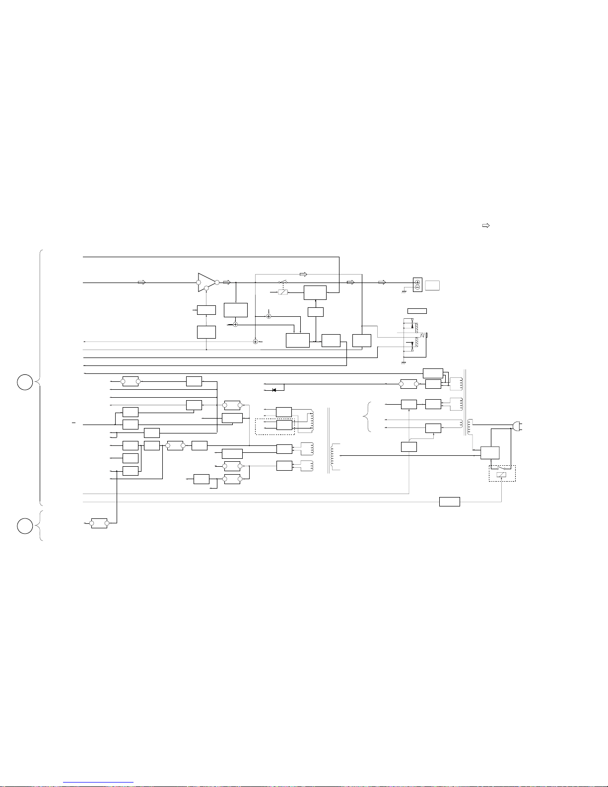
HCD-MDX10
– 53 – – 54 –
– MAIN POWER/SUB POWER SECTION –
VG
VF
VF BUFF
Q14, 15
• R CH : Same as L ch
• SIGNAL PATH
: FM
Rch
Rch
PROTECT
CONTROL
Q432 - 434
RY401
HP.L
OVER LOAD
DET
Q801
Rch
POWER AMP
IC801
FRONT
F RELAY
DBFB
STK MUTE
AC
IN
16
18 14
PHONES
J701
HP
HPLCH
Rch
FRONT
FRONT
SPEAKER
TM401
RELAY
DRIVE
Q435, 436, 431
VOLTAGE
SELECTOR
T11
SUB TRANSFORMER
T881
POWER TRANSFORMER
MAIN
SECTION
J
(Page 48)
VH+
SWITCH
Q437
MUTE
SWITCH
Q439
MUTE
SWITCH
Q439
Lch
+VH SUPP
Q803, 805
MUTE
SWITCH
Q804
+VH
RY-SW
RESET
STANDBY RELAY ON/OFF
FL SW ON/OFF
POWER ON/OFF
AC CUT
PROTECTOR
AC4
AC4
RECT
D907-910
AC3
AC3
RECT
D901-904
IC901
+7V REG
CD/MD MOTOR +7V
ST+10V
3 1
3 1
+10V REG
Q909
TC MOTOR +12V
A+7V
A–7V
3 1
–7V REG
Q951,952,914
+7V REG
Q901,902,913
RECTIFIER
D911
IC905
REG
+5V OUT
Q905
D+5V SW
D+5V UN SW
MD H+5V
RDS D+5V UN SW
AC1
AC1
RECT
D832
RECT
D831
AC2
AC2
–VL
+VL
+VH
–VH
IC904
REG
3 1
5.6V (RED)
RECTIFIER
D918
RECTIFIER
D921
SWITCH
Q906, 903
SWITCH
Q904
+5V REG
Q907
RECTIFIER
D920
RECTIFIER
D919
CD A+5V (SW)
CD D+5V (SW)
RECT
D12-15
DISPLAY
(VIA POWER)
VF
COM MON
SUB TRANS. D+5.6V
3 1
RELAY DRIVE
Q11
SWITCH
Q16, 17
-26V REG
Q12, 13
RECT
D17-20
US, Canadian
RY11
IC903
+12V REG
IC902
REG
IC11
5.6V REG
VS11
RECTIFIER
D24, 25
3 1
REG OUT
Q921
D508
+5V (SWBY) (DISPLAY)
+5.6V (SWBY)
E
MUTE
SWITCH
Q412, 411
MD BACKUP
MD 3.3V
MD A3.3V
RESET
IC371
3 5
BD (MD)
SECTION (2)
F
09
(Page 46)
-12V
+12V
Page 47
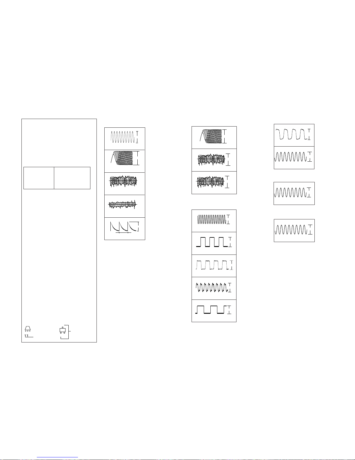
HCD-MDX10
IC101 #ª FE
1
2
3
4
5
WAVEFORMS
– BD (CD) SECTION –
IC101 ^§ XTAI
IC101 %¡ RF AC
IC101 $¡ TE
IC101 @§ MDP
• Indication of transistor
– PANEL (1/2) SECTION –
1
2
IC501 !¡ XC-OUT
IC501 !£ X-OUT
– MAIN (3/4) SECTION –
IC601 (¡ X OUT
1
3.1Vp-p
16.9MHz
1.2Vp-p
(PLAY)
2.5V
APPROX 500mVp-p
(
PLAY
)
2.5V
APPROX 200m Vp-p
(
PLAY
)
7.5µsec
2.4Vp-p
16MHz
5.5Vp-p
32.768kHz
5.2Vp-p
12.5MHz
3.4Vp-p
– 55 – – 56 –
THIS NOTE IS COMMON FOR PRINTED WIRING
BOARDS AND SCHEMATIC DIAGRAMS.
(In addition to this, the necessary note is printed
in each block.)
For schematic diagrams.
Note:
• All capacitors are in µF unless otherwise noted. pF: µµF
50 WV or less are not indicated except for electrolytics
and tantalums.
• All resistors are in Ω and 1/
4
W or less unless otherwise
specified.
•¢: internal component.
• C : panel designation.
For printed wiring boards.
Note:
• X : parts extracted from the component side.
• p : parts mounted on the conductor side.
•®: Through hole.
• b : Pattern from the side which enables seeing.
(The other layers' patterns are not indicated.)
• U : B+ Line.
• V : B– Line.
• H : adjustment for repair.
• Voltages and waveforms are dc with respect to ground
under no-signal (detuned) conditions.
• Voltages are taken with a VOM (Input impedance 10 MΩ).
Voltage variations may be noted due to normal production tolerances.
• Waveforms are taken with a oscilloscope.
Voltage variations may be noted due to normal production tolerances.
• Circled numbers refer to waveforms.
• Signal path.
F : FM
g : VIDEO
E : PB (DECK A)
d : PB (DECK B)
G : REC (DECK B)
J : CD
c : CD (digital out)
a : PB (MD)
j : REC (MD)
p : PB (digital out)
l : REC (dihgital in)
• Abbreviation
CND : Canadian model.
G : German model.
SP : Singapore model.
MY : Malaysia model.
HK : Hong Kong model.
AR : Argentine model.
KR : korea model.
AUS : Australian model.
Note:
The components identified by mark ! or dotted
line with mark ! are critical for safety.
Replace only with part
number specified.
Note:
Les composants identifiés par
une marque ! sont critiques
pour la sécurité.
Ne les remplacer que par une
piéce portant le numéro
spécifié.
– BD (MD) (1/2) SECTION –
1
2
3
4
5
6
7
8
IC101 1, 2 (I, J) (PLAY mode)
IC101 4 (A) (PLAY mode)
IC101 8, 9 (E, F) (PLAY mode)
IC121 !§ (OSCI)
IC121 @¶ (LRCK)
IC121 @ª (FS256)
IC121 @• (XBCK)
IC121 (º (FS4)
0.46Vp-p
0.1Vp-p
0.06Vp-p
3.1Vp-p
22.581MHz
3.2Vp-p
44.1kHz
3.8Vp-p
2.822MHz
3.8Vp-p
11.29MHz
3.2Vp-p
176.4kHz
– BD (MD) (2/2) SECTION –
– MD DIGITAL (1/2) SECTION –
IC316 !£ (XOUT)
1
3.2Vp-p
10MHz
C
These are omitted
EB
Q
C
These are omitted
EB
Page 48
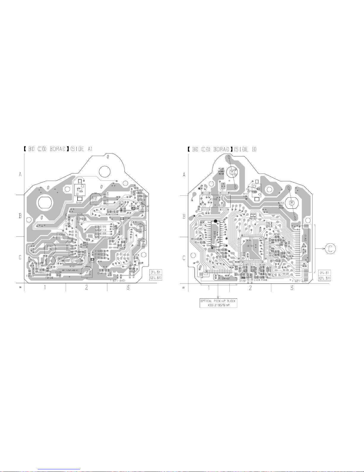
HCD-MDX10
8-3. PRINTED WIRING BOARD – BD (CD) SECTION –
• See page 40 for Circuit Boards Location.
– 57 –
– 58 –
(Page 75)
(VC)
(RP)
(AGCCON)
(FE)
(FF1)
(TE)
19
Page 49
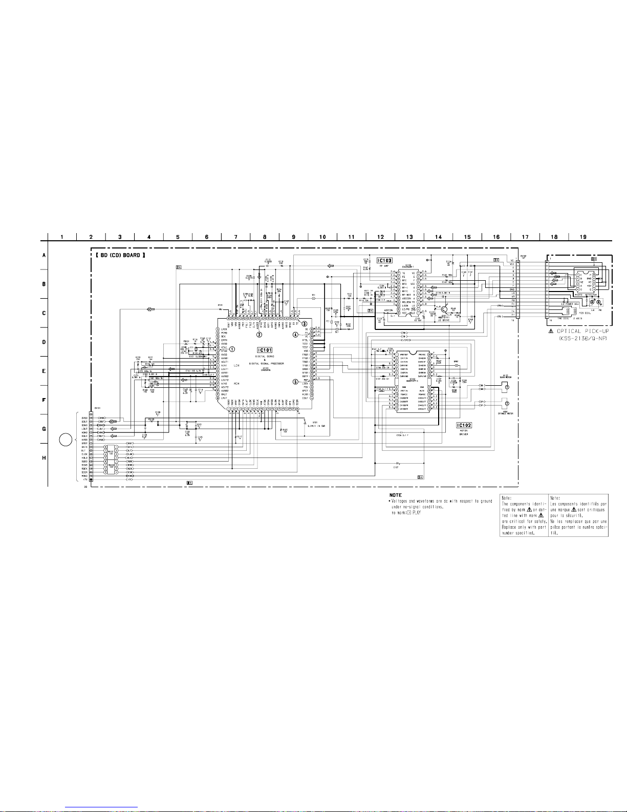
HCD-MDX10
– 59 –
– 60 –
8-4. SCHEMATIC DIAGRAM – BD (CD) SECTION –
• See page 55 for Waveforms.
(Page 67)
TP
(TE)
TP
(RP)
TP (AGCCON)
TP
(FE)
TP
(VC)
68
10V
220
19P
NC
C
Page 50
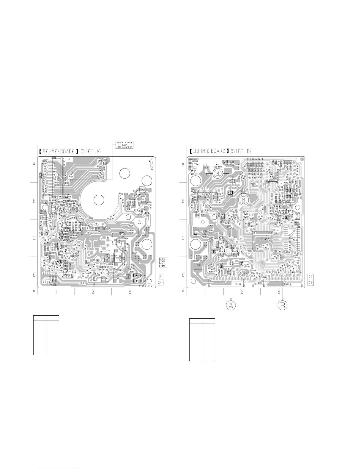
HCD-MDX10
8-5. PRINTED WIRING BOARD – BD (MD) SECTION –
• See page 40 for Circuit Boards Location.
– 61 –
– 62 –
(Page 89)
(Page 89)
D101 A-1
D181 D-3
D183 D-3
IC103 B-1
IC123 D-2
IC171 D-1
Q102 B-1
Q103 B-1
Q104 B-1
IC101 A-3
IC121 C-3
IC124 C-3
IC152 B-1
IC181 C-1
IC192 D-1
Q101 B-3
Q162 B-3
Q163 B-3
Q181 C-1
Q182 C-2
Ref. No. Location
• Semiconductor
Location
Ref. No. Location
• Semiconductor
Location
Page 51
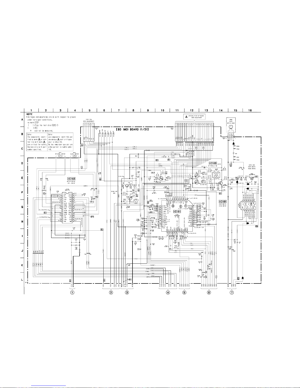
HCD-MDX10
– 63 – – 64 –
8-6. SCHEMATIC DIAGRAM – BD (MD) (1/2) SECTION –
• See page 56 for Waveforms. • See page 109 for IC Block Diagrams. • See page 112 for IC Pin Functions.
(Page 65)
(Page 65)
(Page 65)
(Page 66)
(Page 66) (Page 66)
(Page 66)
Page 52
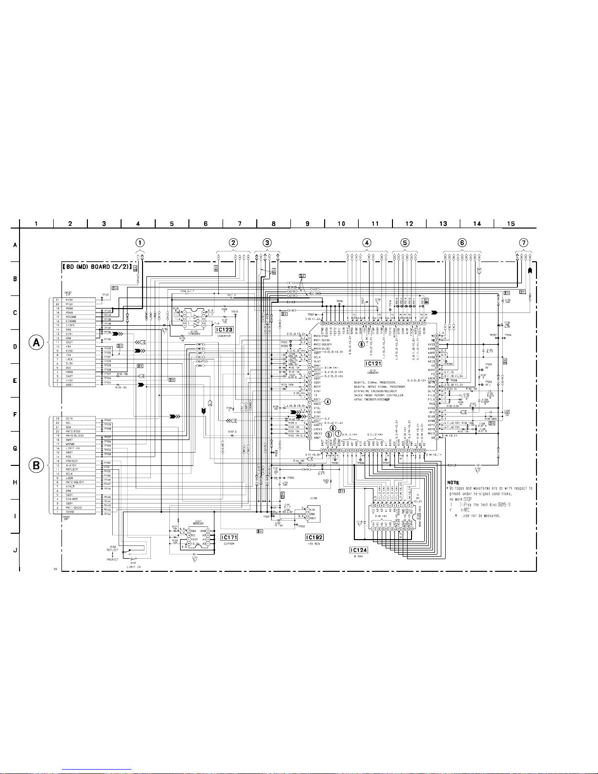
HCD-MDX10
– 65 – – 66 –
(Page 63)
(Page 63)
(Page 63)
(Page 64)
(Page 64)
(Page 64)
(Page 64)
(Page 93)
(Page 93)
BA033FP-E2
8-7. SCHEMATIC DIAGRAM – BD (MD) (2/2) SECTION –
• See page 56 for Waveforms. • See page 109 for IC Block Diagrams. • See page 113 for IC Pin Functions.
Page 53

HCD-MDX10
– 67 –
– 68 –
8-8. SCHEMATIC DIAGRAM – MAIN (1/4) SECTION –
• See page 75 for Printed Wiring Board.
(Page 59)
(Page 71) (Page 72) (Page 73)
(Page 69)
(Page 69)
MICON
INTERFACE
Page 54
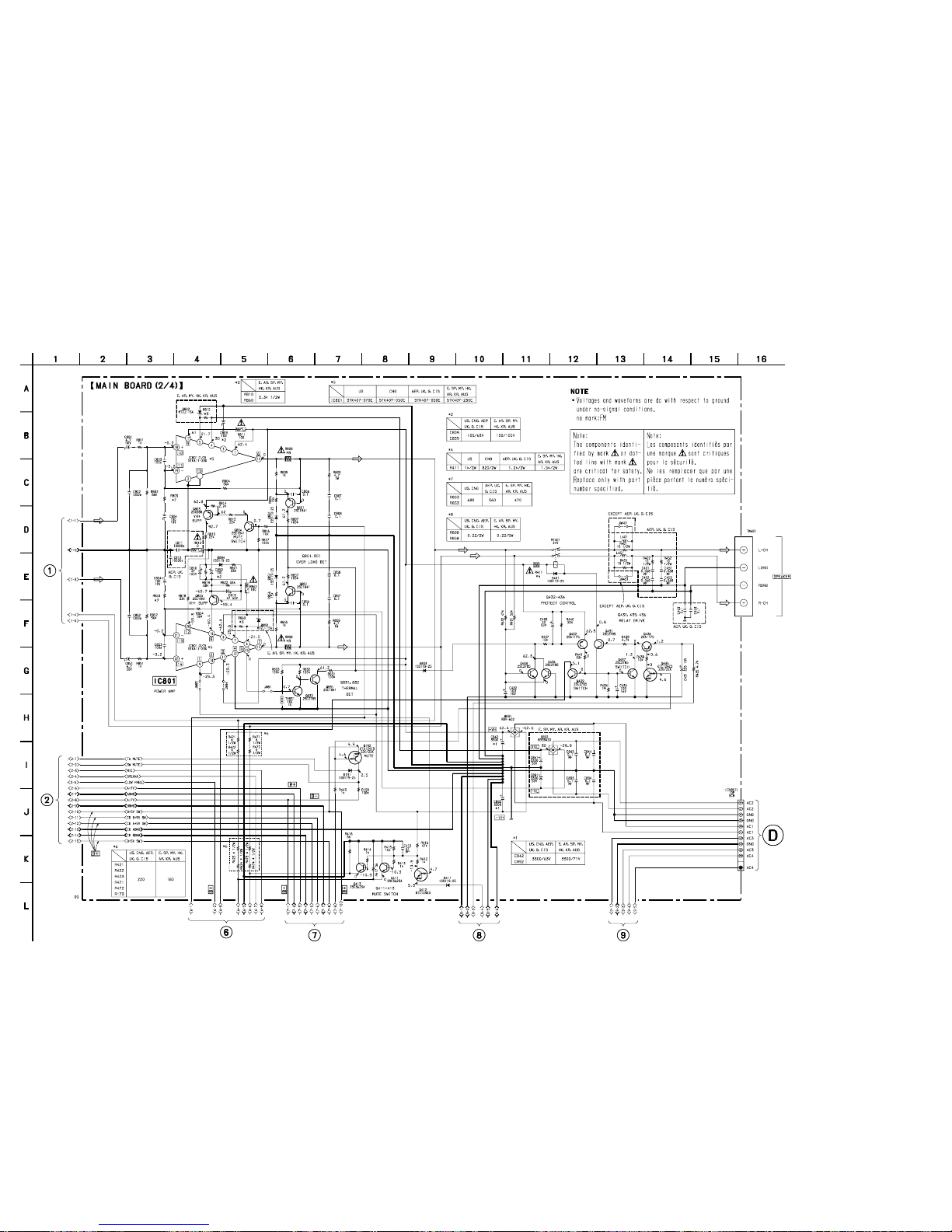
HCD-MDX10
8-9. SCHEMATIC DIAGRAM – MAIN (2/4) SECTION –
• See page 75 for Printed Wiring Board.
– 69 – – 70 –
(Page
68)
(Page
68)
(Page 73)
(Page 74) (Page 74) (Page 74)
(Page 104)
Page 55
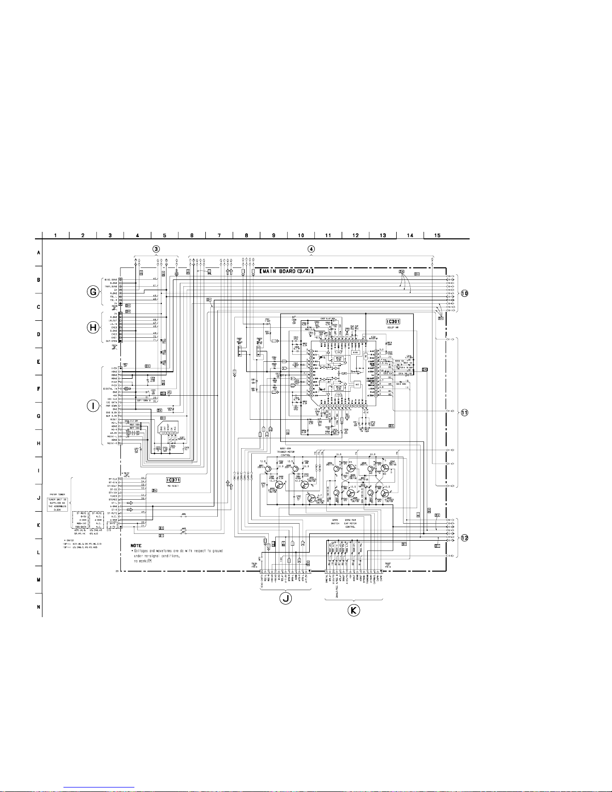
HCD-MDX10
– 71 –
– 72 –
8-10. SCHEMATIC DIAGRAM – MAIN (3/4) SECTION –
• See page 56 for Waveforms.
• See page 75 for Printed Wiring Board.
• See page 111 for IC Block Diagrams.
(Page 67) (Page 67)
(Page 73)
(Page 73)
(Page 73)
(Page 100)
(Page 100)
(Page 80)
(Page 82)
Page 56
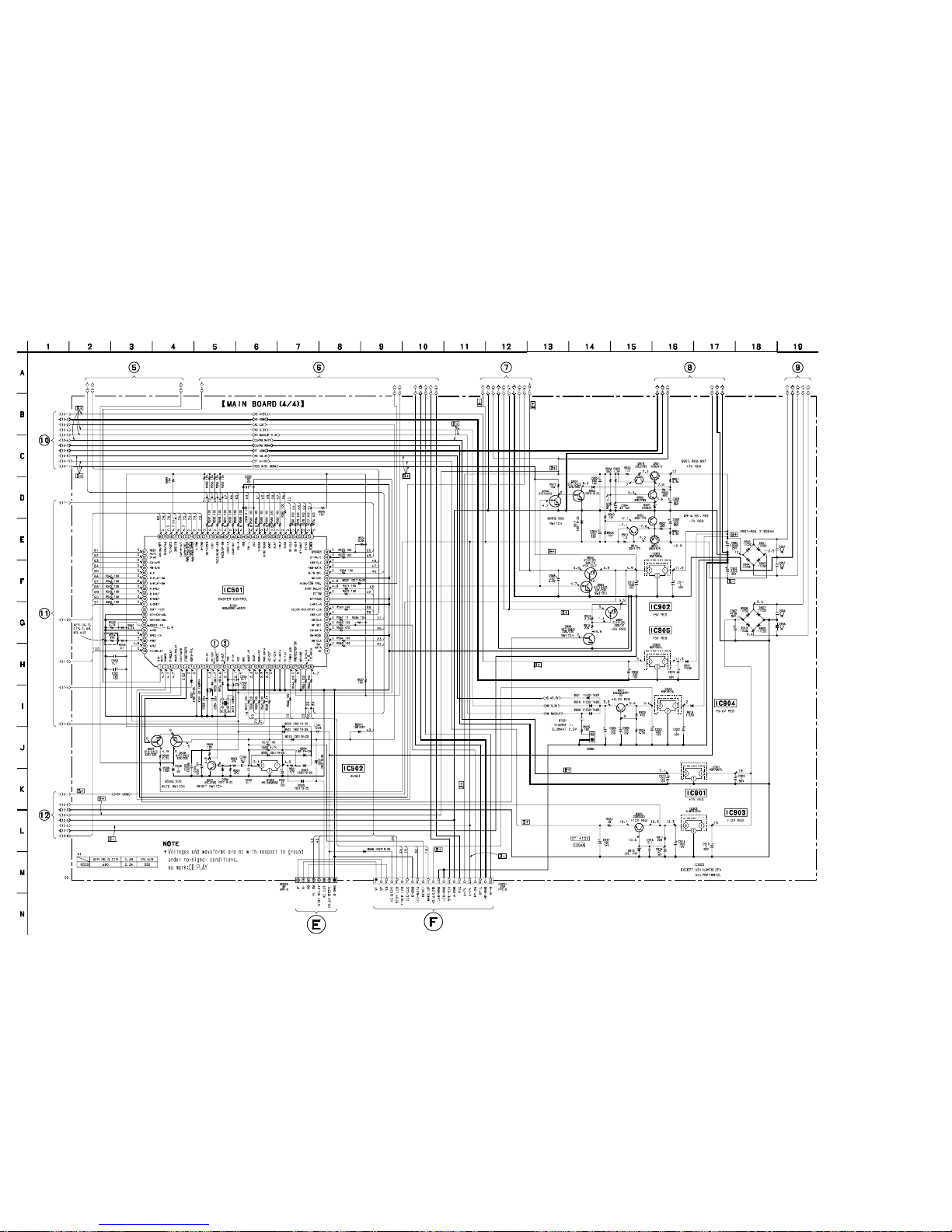
HCD-MDX10
8-11. SCHEMATIC DIAGRAM – MAIN (4/4) SECTION –
• See page 75 for Printed Wiring Board.
• See page 116 for IC Pin Functions.
– 73 – – 74 –
(Page
72)
(Page
72)
(Page
72)
(Page 106)
(Page 84)
(Page 68) (Page 69) (Page 69) (Page 70) (Page 70)
Page 57
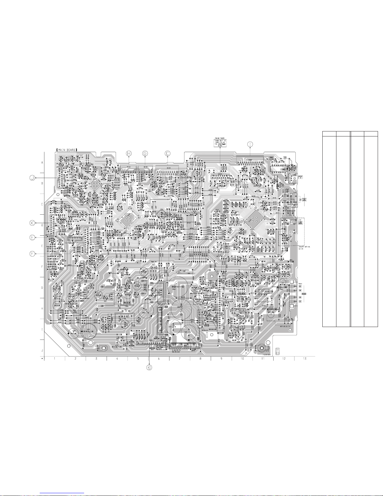
HCD-MDX10
8-12. PRINTED WIRING BOARD – MAIN SECTION –
• See page 40 for Circuit Boards Location.
Ref. No. Location
• Semiconductor Location
Ref. No. Location
D141 F-11
D191 F-12
D331 E-1
D333 F-1
D334 F-1
D335 F-1
D371 B-8
D372 B-8
D373 B-8
D401 G-11
D411 F-5
D501 D-6
D502 D-6
D503 D-7
D504 D-6
D505 D-7
D506 D-7
D507 C-8
D508 D-2
D509 D-8
D510 D-8
D551 E-6
D552 D-10
D801 I-9
D802 H-9
D803 G-11
D804 H-8
D831 I-6
D832 J-7
D851 I-10
D852 H-8
D901 J-4
D902 I-4
D903 J-4
D904 I-4
D905 H-2
D906 G-2
D907 I-5
D908 I-5
D909 I-5
D910 I-5
D911 H-4
D915 I-3
D917 F-3
D918 H-4
D919 F-6
D920 F-6
D921 F-6
IC101 D-10
IC301 B-3
IC371 B-11
IC381 A-12
IC382 B-13
IC501 D-5
IC502 D-7
IC801 G-9
IC901 G-6
IC902 G-4
IC903 H-4
IC904 H-4
IC905 G-5
Q111 E-10
Q112 E-10
Q113 F-10
Q161 D-10
Q162 C-9
Q163 E-9
Q191 E-12
Q192 F-12
Q201 E-10
Q251 D-10
Q331 C-2
Q332 C-2
Q333 C-2
Q334 C-2
Q335 E-1
Q336 F-1
Q337 F-1
Q338 E-1
Q339 F-1
Q340 E-1
Q341 E-1
Q342 F-1
Q343 E-1
Q411 G-1
Q412 F-4
Q413 G-1
Q431 F-12
Q432 G-11
Q433 G-11
Q434 G-11
Q435 F-11
Q436 F-12
Q437 F-12
Q439 F-12
Q501 D-7
Q508 D-7
Q509 D-7
Q801 I-10
Q803 G-8
Q804 G-9
Q805 G-9
Q831 H-10
Q832 H-10
Q851 H-10
Q901 G-2
Q902 H-2
Q903 G-2
Q904 F-4
Q905 F-4
Q906 G-2
Q907 G-4
Q908 G-4
Q909 H-4
Q913 G-3
Q914 F-3
Q921 G-5
Q951 F-2
Q952 G-3
– 75 – – 76 –
(Page 77)
(Page 82)
(Page 108)
(Page 87)
(Page 102)
(Page 97) (Page 97)
(Page 90)
(Page 58)
Page 58
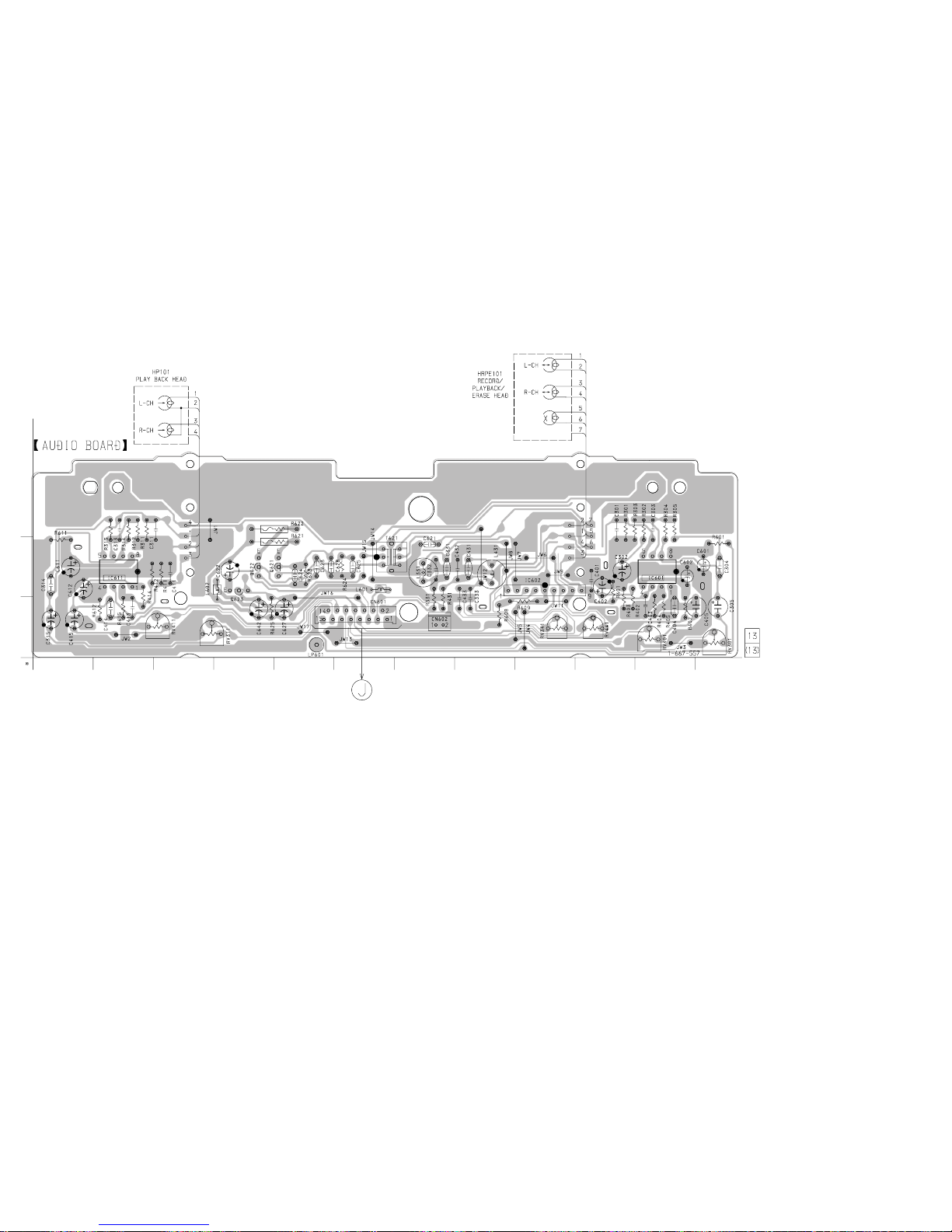
HCD-MDX10
– 77 –
– 78 –
8-13. PRINTED WIRING BOARD – DECK SECTION –
• See page 40 for Circuit Boards Location.
(Page 75)
1
C
B
A
23456789101112
Page 59
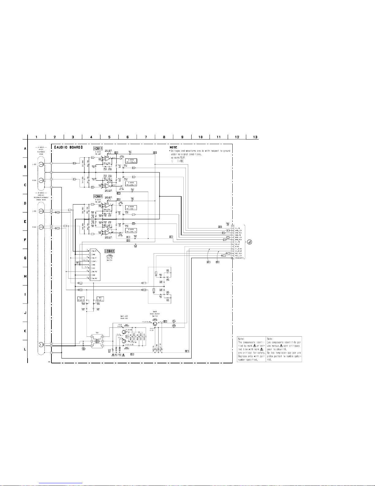
HCD-MDX10
– 79 – – 80 –
8-14. SCHEMATIC DIAGRAM – DECK SECTION –
(Page 71)
Page 60
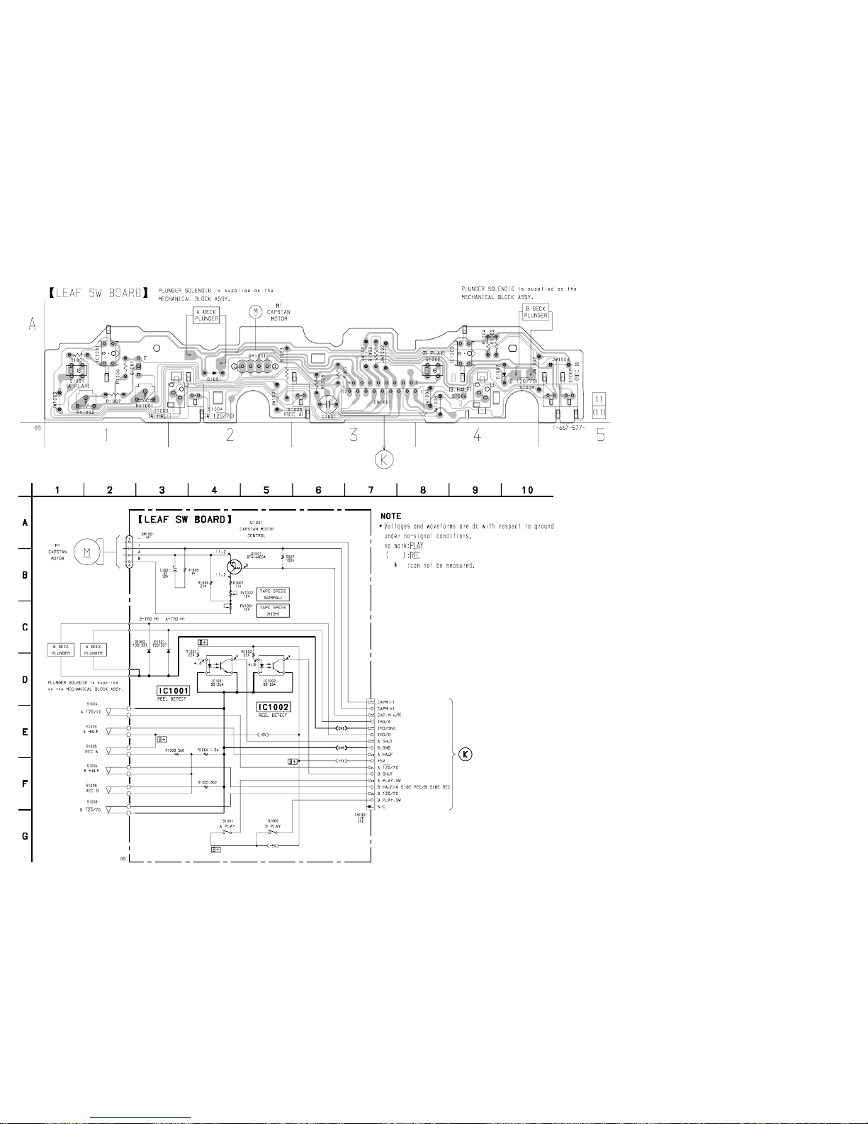
HCD-MDX10
– 81 –
– 82 –
8-16. SCHEMATIC DIAGRAM – LEAF SW SECTION –
8-15. PRINTED WIRING BOARD – LEAF SW SECTION –
• See page 40 for Circuit Boards Location.
(Page 75)
(Page 72)
Page 61
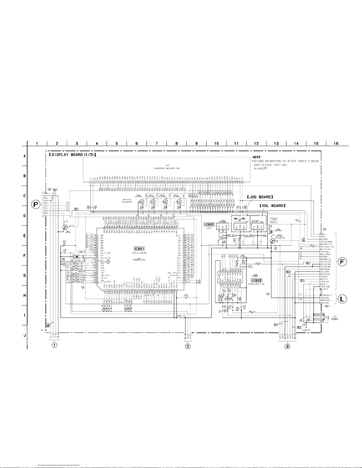
HCD-MDX10
– 83 – – 84 –
8-17. SCHEMATIC DIAGRAM – DISPLAY (1/2) SECTION –
• See page 87 for Printed Wiring Board.
• See page 111 for IC Block Diagrams.
• See page 118 for IC Pin Functions.
(Page 85)
(Page 85)
(Page 86) (Page 86)
(Page 74)
(Page 104)
Page 62
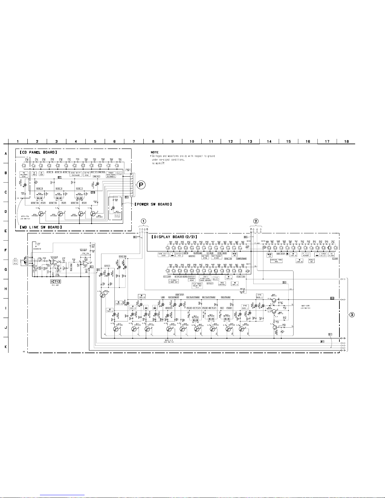
HCD-MDX10
– 85 – – 86 –
8-18. SCHEMATIC DIAGRAM – DISPLAY (2/2) SECTION –
(Page 83)
(Page 83) (Page 83)
(Page
84)
Page 63
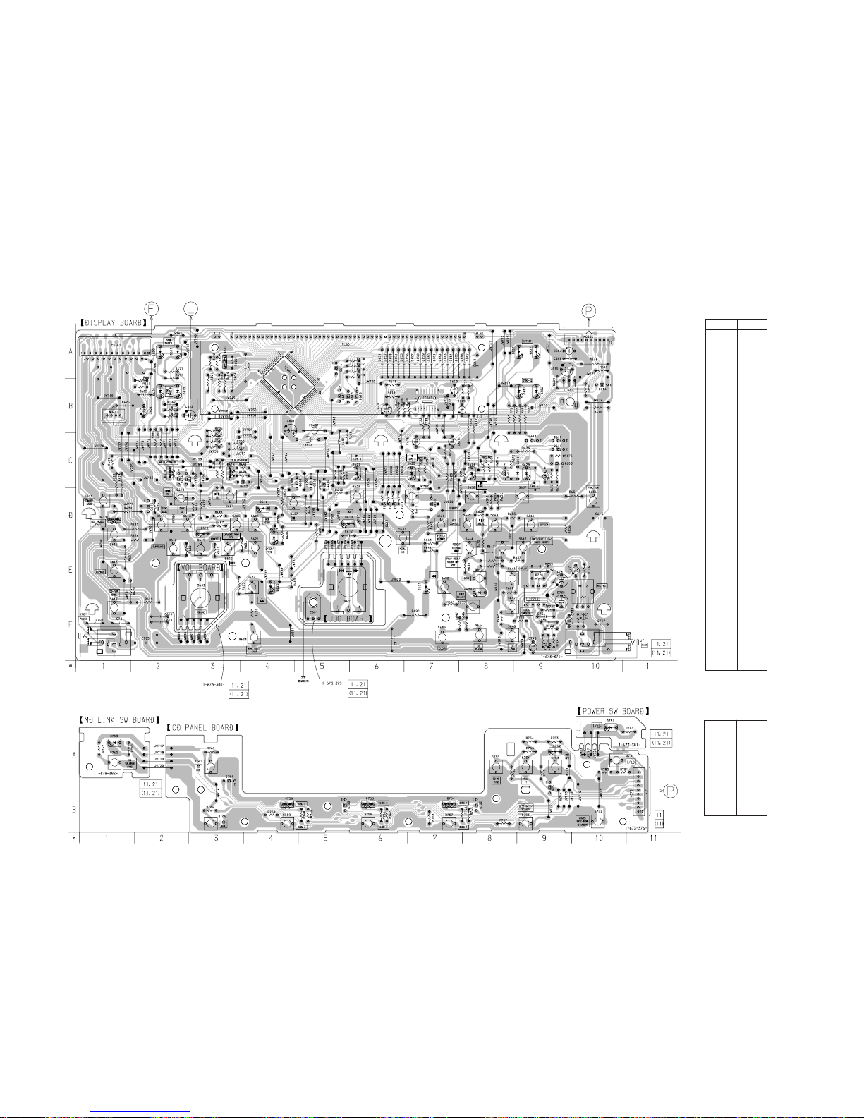
HCD-MDX10
– 87 –
– 88 –
8-19. PRINTED WIRING BOARD – DISPLAY SECTION –
• See page 40 for Circuit Boards Location.
Ref. No. Location
• Semiconductor
Location
D610 C-9
D611 A-2
D612 B-2
D613 D-1
D614 C-2
D615 C-3
D616 D-4
D617 D-4
D618 D-3
D619 D-6
D620 E-4
D621 E-7
D622 C-6
D623 C-7
D624 C-8
D625 C-9
D626 B-9
D627 A-9
D628 E-8
D629 A-2
D630 B-2
D631 B-9
D632 A-9
IC601 A-4
IC602 B-10
IC603 B-7
IC712 E-9
Q601 C-8
Q602 C-9
Q603 C-9
Q604 C-3
Q605 D-2
Q606 C-2
Q607 C-4
Q608 C-5
Q609 C-5
Q610 C-5
Q611 C-9
Q612 C-9
Q613 C-9
Q614 B-10
Q615 D-7
Q616 A-5
Q617 B-5
Q618 B-6
Q619 B-6
Ref. No. Location
• Semiconductor
Location
D751 A-10
D752 A-9
D753 A-1
D754 B-7
D755 B-6
D756 B-4
Q751 B-9
Q752 B-8
Q753 B-5
Q754 A-3
(Page 75) (Page 101)
(Page 88)
(Page 88)
Page 64
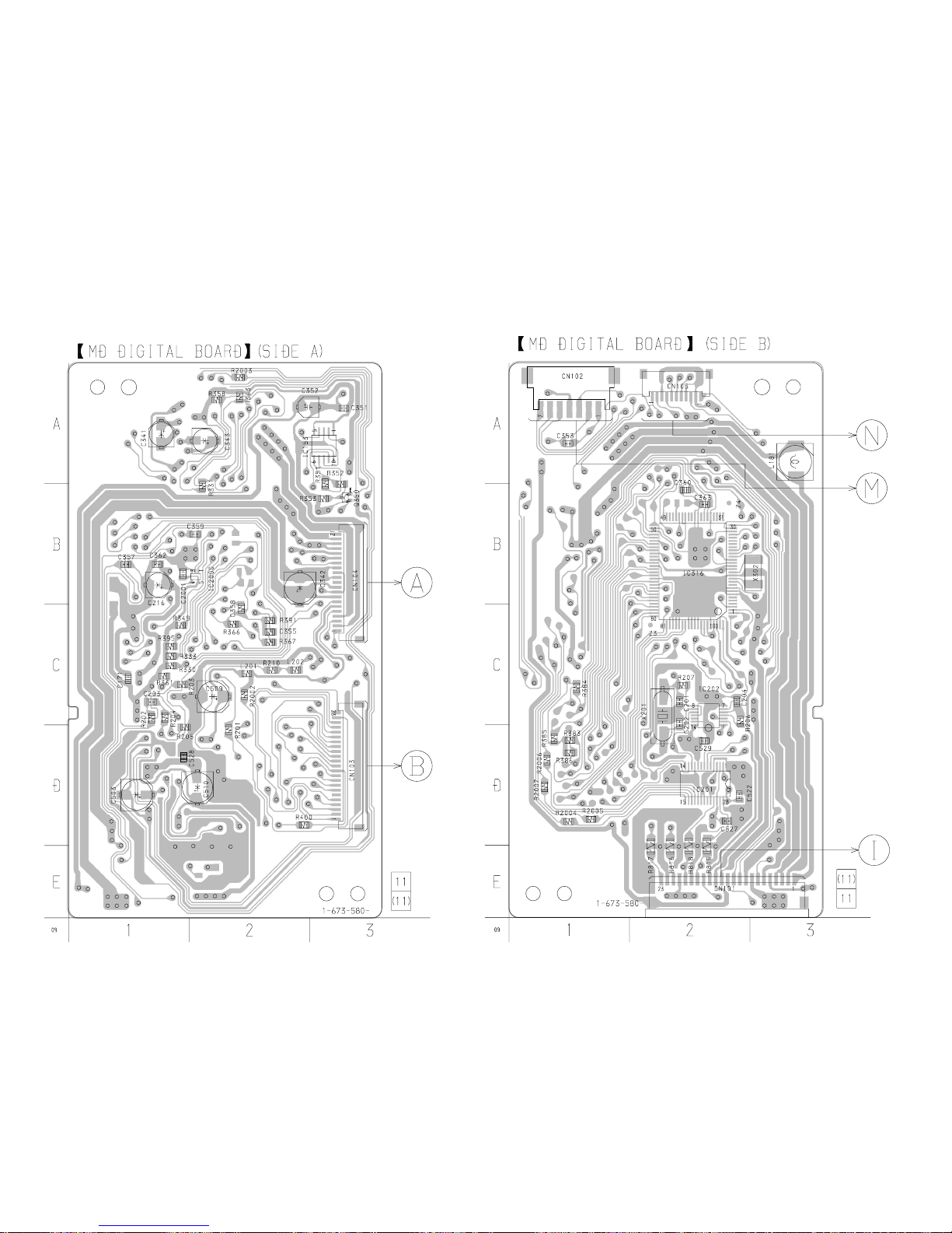
HCD-MDX10
– 89 – – 90 –
8-20. PRINTED WIRING BOARD – MD DIGITAL SECTION –
• See page 40 for Circuit Boards Location.
(Page 62)
(Page 62)
(Page 101)
(Page 96)
(Page 76)
Page 65
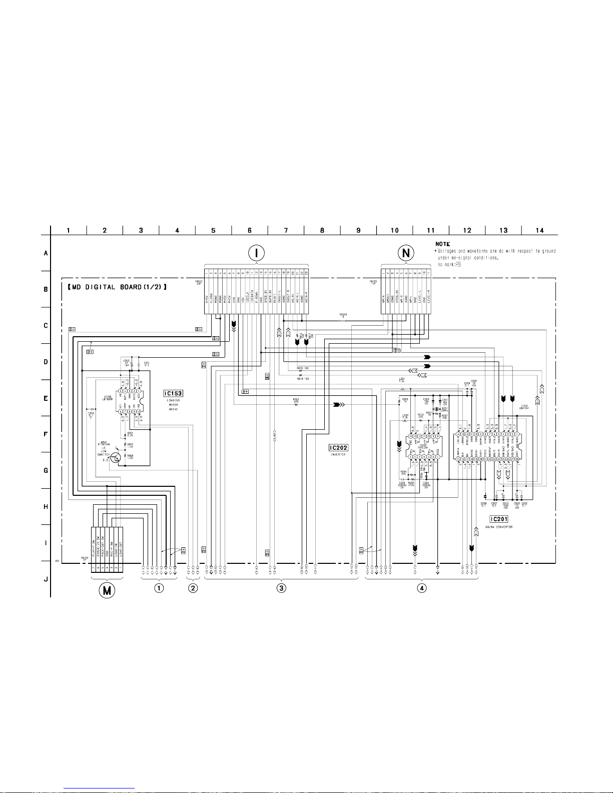
HCD-MDX10
8-21. SCHEMATIC DIAGRAM – MD DIGITAL (1/2) SECTION –
• See page 111 for IC Block Diagrams.
– 91 – – 92 –
(Page 71) (Page 103)
(Page 95)
(Page 93) (Page 93) (Page 94) (Page 94)
Page 66
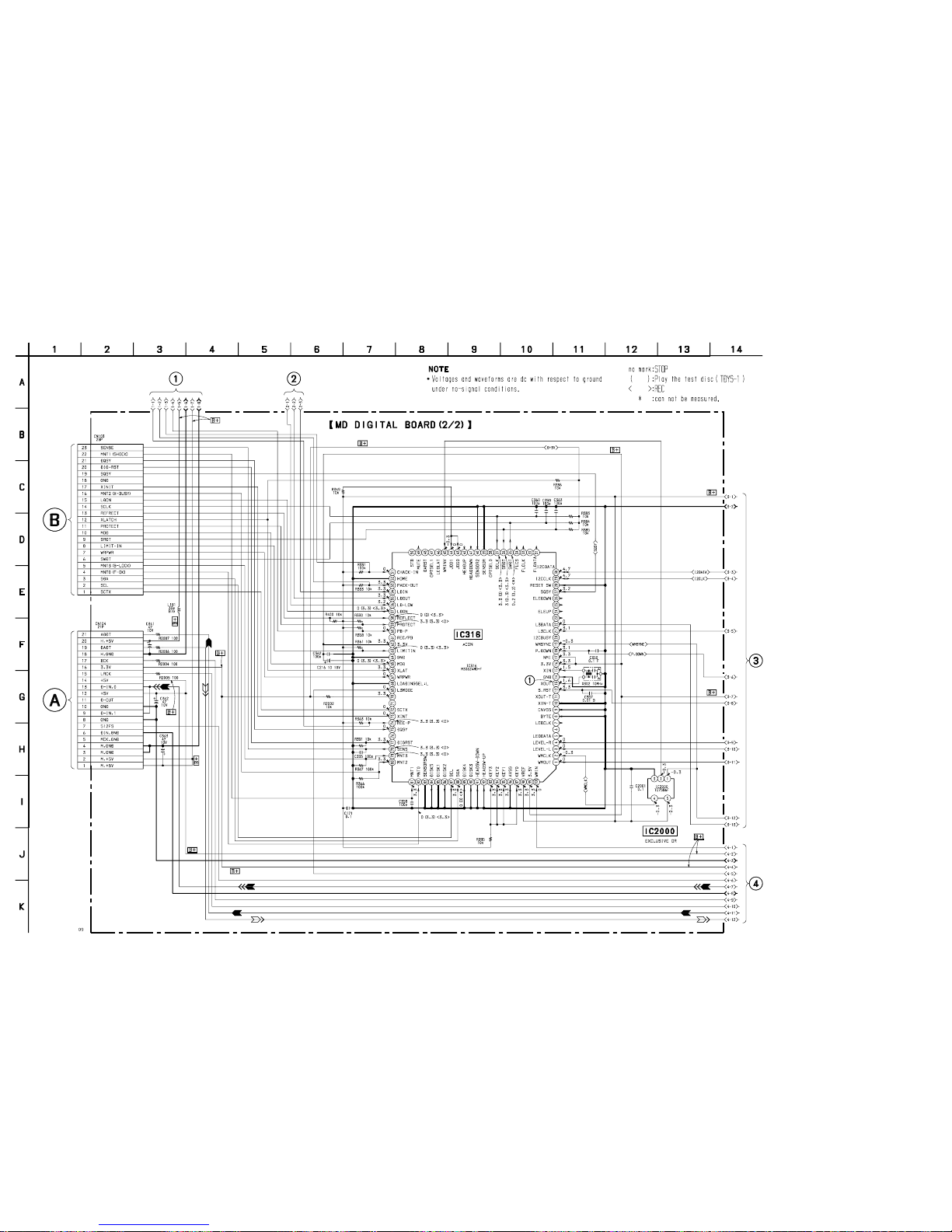
HCD-MDX10
8-22. SCHEMATIC DIAGRAM – MD DIGITAL (2/2) SECTION –
• See page 89 for Printed Wiring Board.
– 93 – – 94 –
(Page 65)
(Page 65)
(Page 91) (Page 91)
(Page 91)
(Page 92)
Page 67
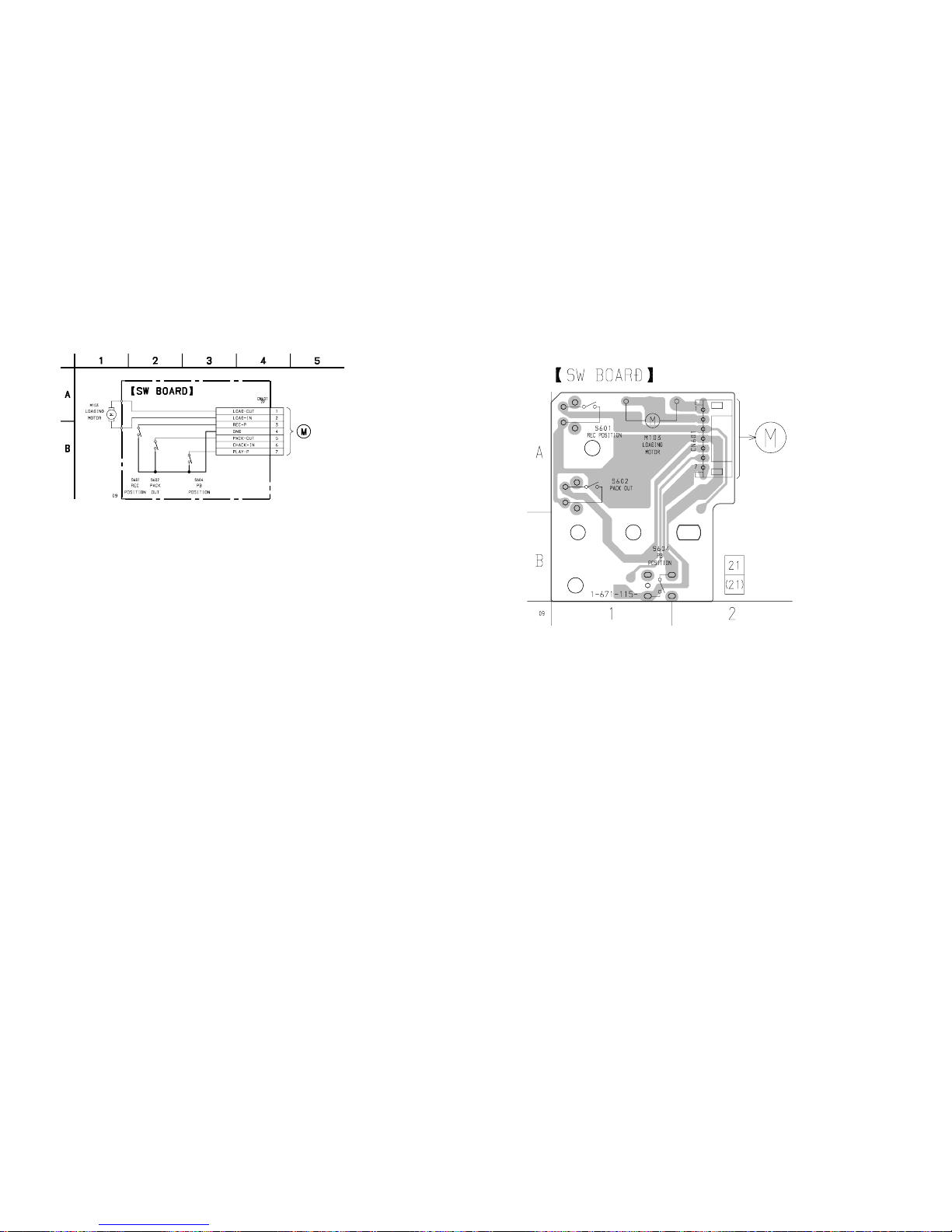
HCD-MDX10
8-23. SCHEMATIC DIAGRAM – BD SWITCH SECTION –
– 95 – – 96 –
8-24. PRINTED WIRING BOARD – BD SWITCH SECTION –
• See page 40 for Circuit Boards Location.
(Page 91)
(Page 90)
Page 68
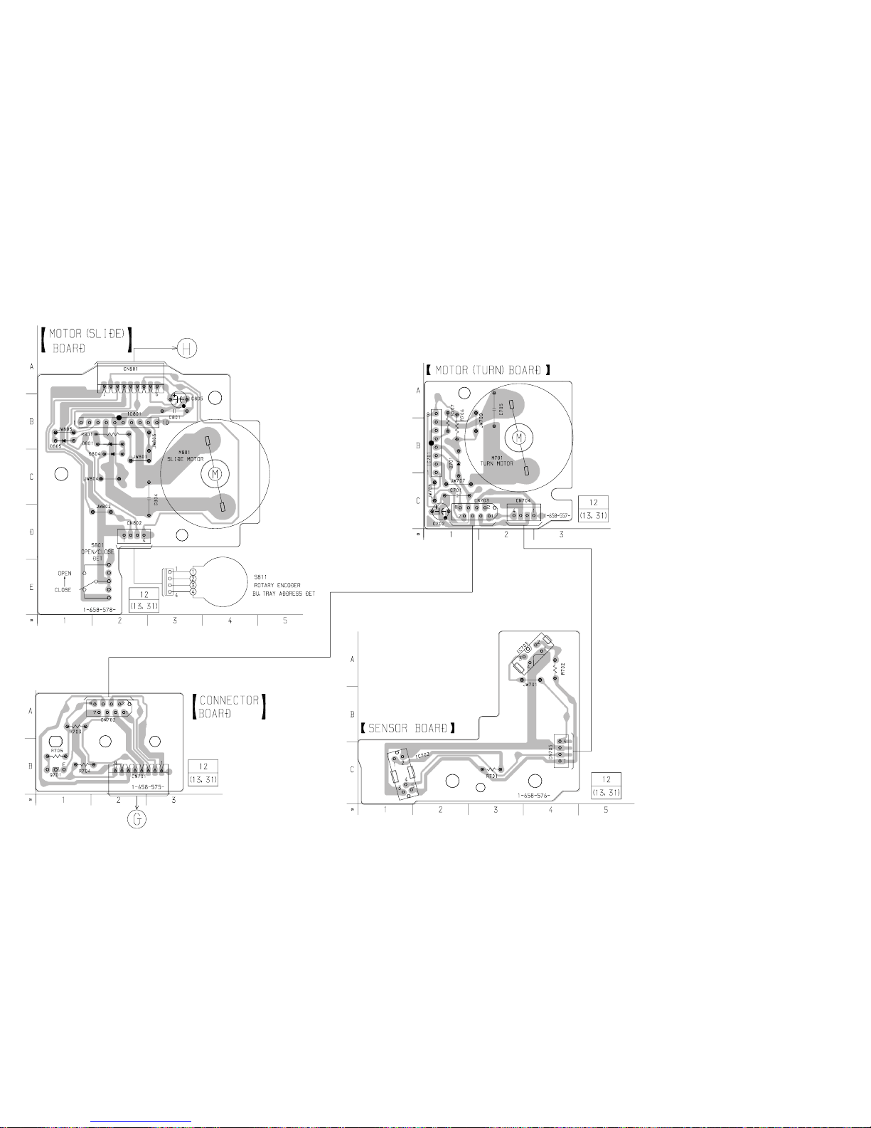
HCD-MDX10
– 97 – – 98 –
8-25. PRINTED WIRING BOARD – CD MOTOR SECTION –
• See page 40 for Circuit Boards Location.
(Page 75)
(Page 75)
Page 69
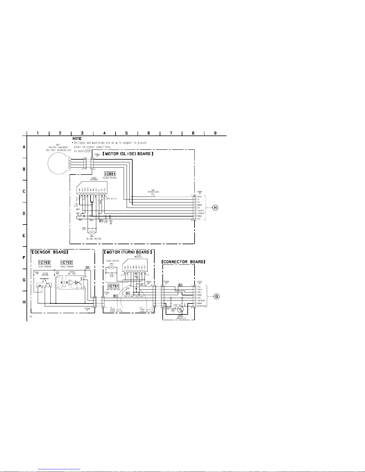
HCD-MDX10
8-26. SCHEMATIC DIAGRAM – CD MOTOR SECTION –
– 99 – – 100 –
(Page 71)
(Page 71)
1SS119
1SS119
MTZJ-T-72-5.6C (M)
MTZJ-T-72-3.6C (M)
Page 70
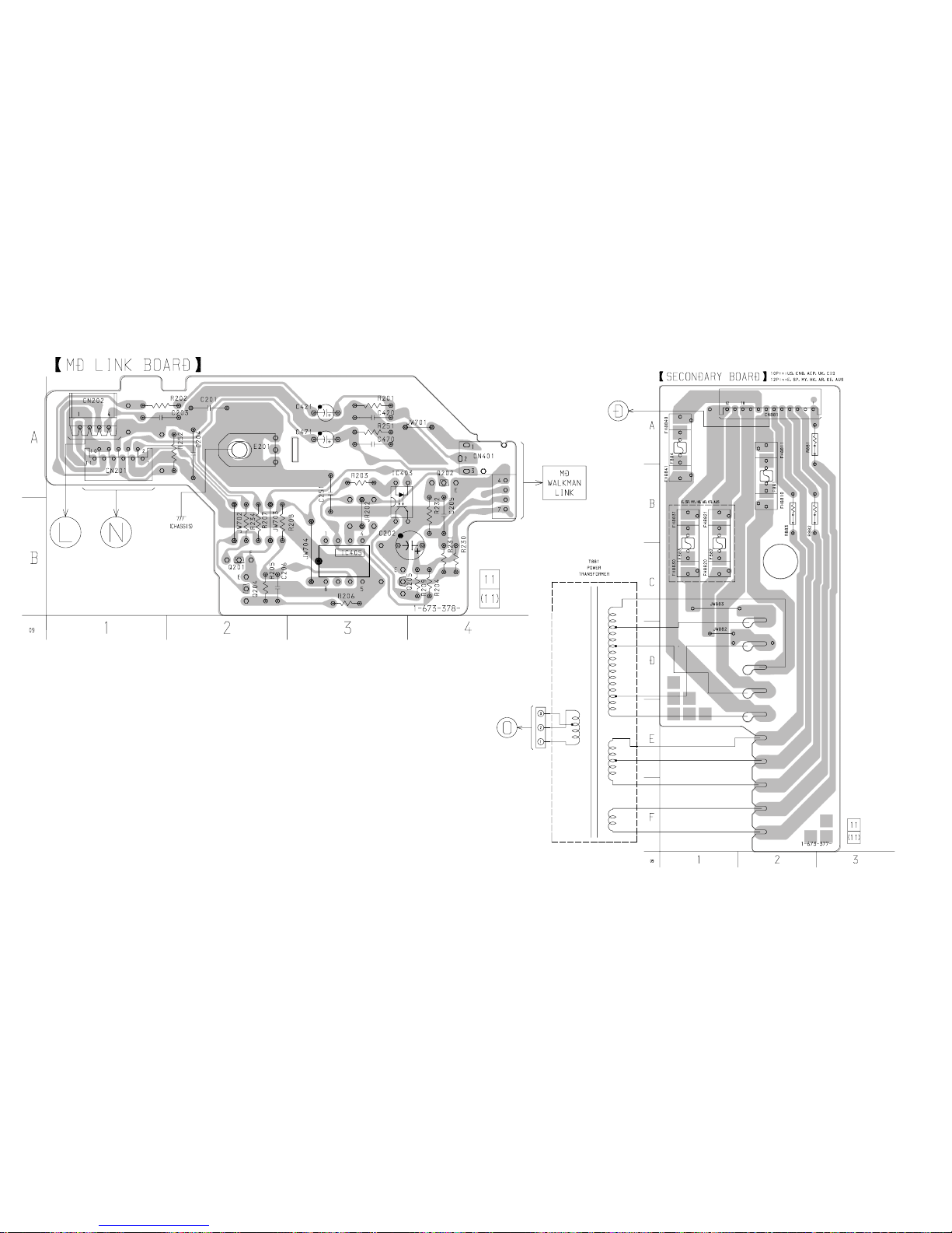
HCD-MDX10
– 101 – – 102 –
8-27. PRINTED WIRING BOARD – MD LINK SECTION –
• See page 40 for Circuit Boards Location.
(Page 87) (Page 90)
(Page 75)
(Page 108)
Page 71
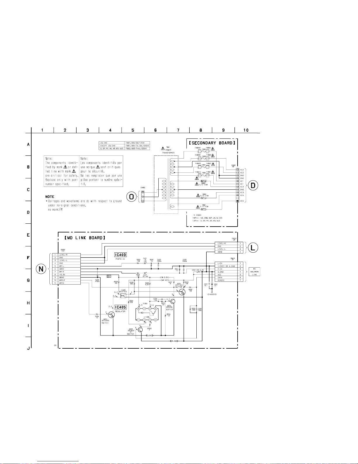
HCD-MDX10
8-28. SCHEMATIC DIAGRAM – MD LINK SECTION –
– 103 – – 104 –
(Page 105)
(Page 70)
(Page 84)
(Page 92)
Page 72
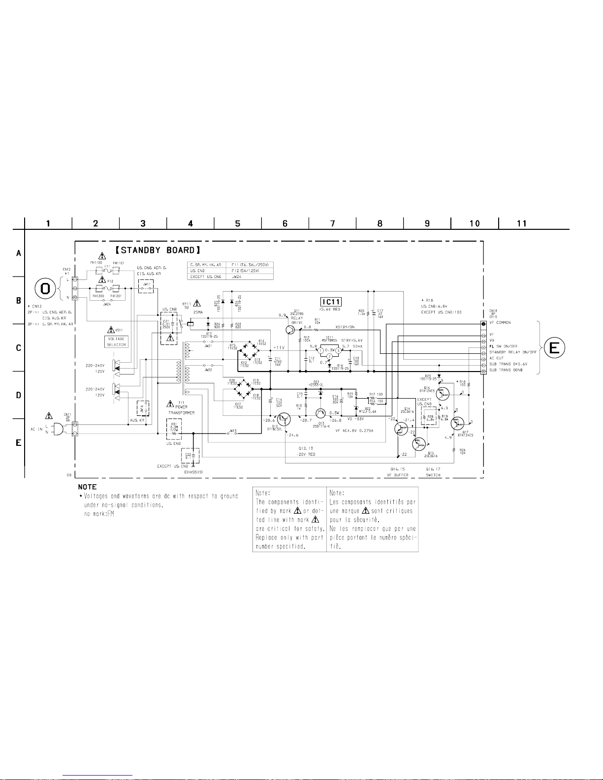
HCD-MDX10
– 105 – – 106 –
8-29. SCHEMATIC DIAGRAM – POWER SECTION –
(Page 103)
(Page 73)
Page 73
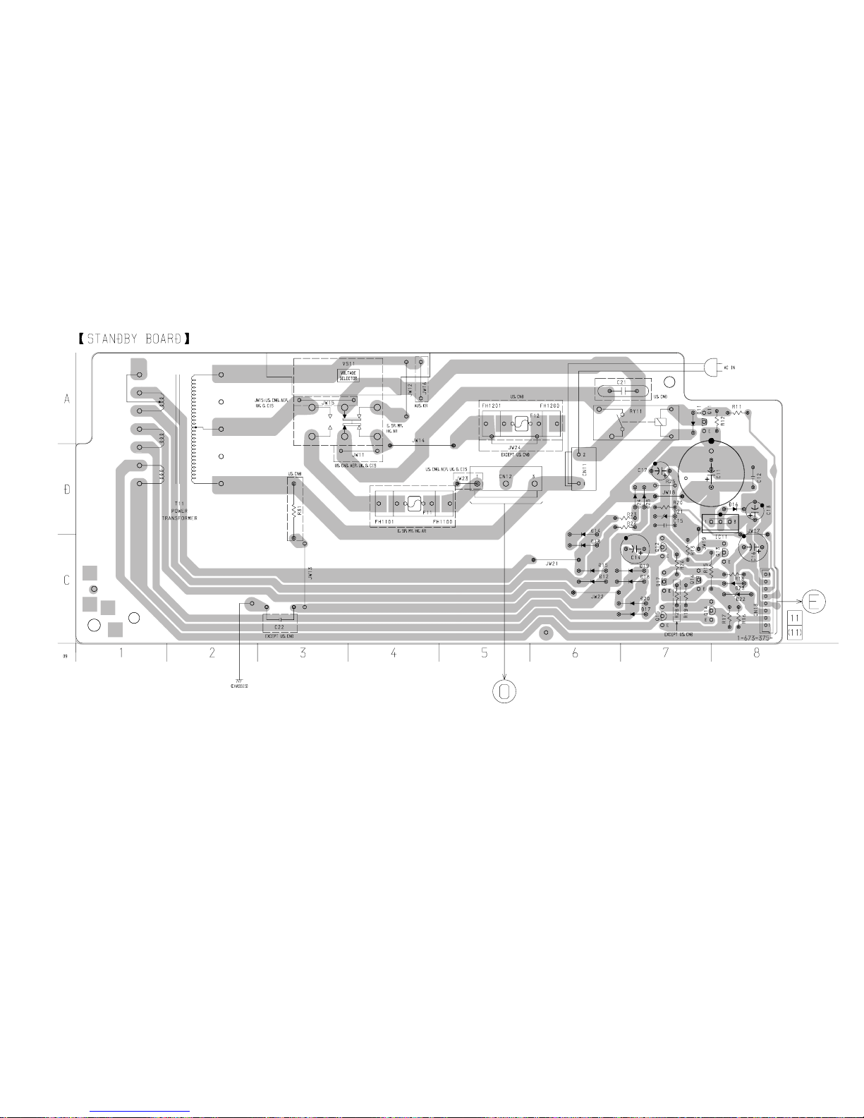
HCD-MDX10
– 107 – – 108 –
8-30. PRINTED WIRING BOARD – POWER SECTION –
• See page 40 for Circuit Boards Location.
(Page 102)
(Page 75)
Page 74
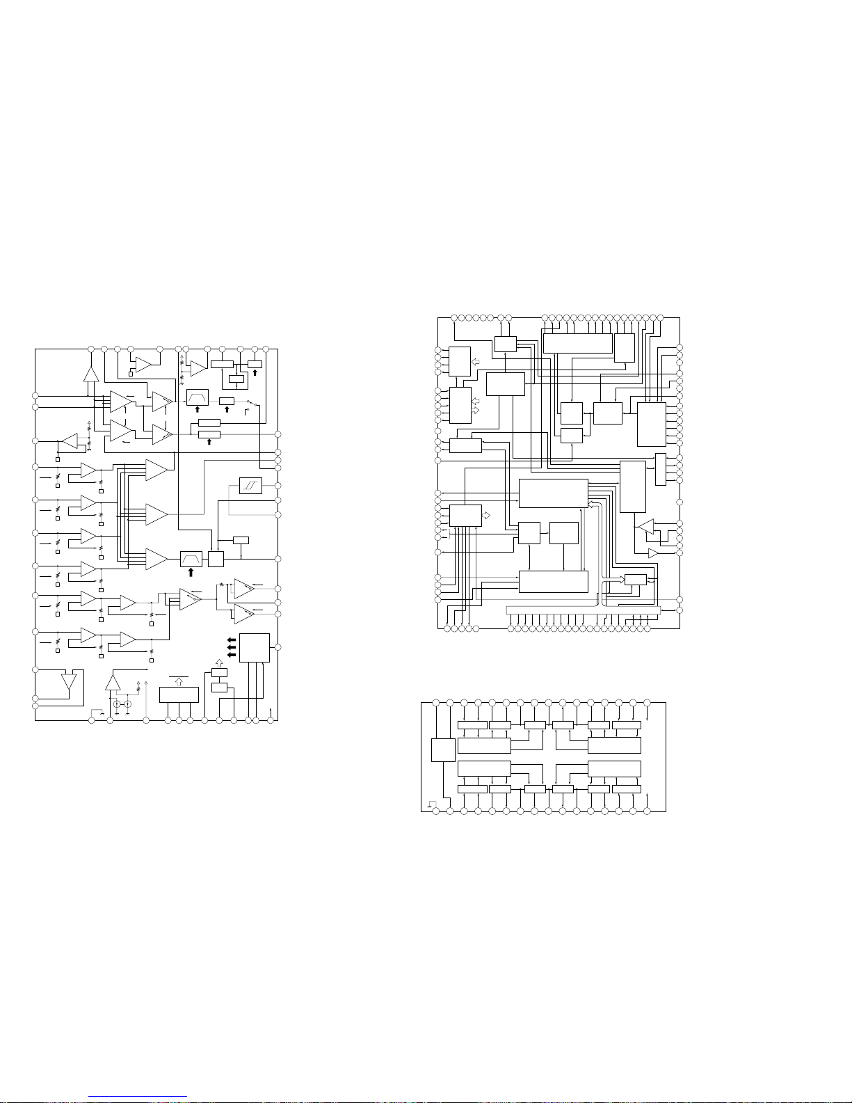
HCD-MDX10
8-31. IC BLOCK DIAGRAMS
• BD (MD) Board
IC101 CXA2523AR
– 109 – – 110 –
–1
–2
+
–
IVR
BB
+
–
IVR
AA
+
–
IVR
CC
+
–
IVR
DD
+
–
IVR
+
–
EE
EE'
EFB TESW
PTGR
48
MORFO47MORFI46RFO45OPN44OPO43ADDC42COMPP41COMPO40AGCI39RF AGC38RF37PEAK
36
BOTM
35
ABCD
34
FE
33
AUX
32 ADFG
31 ADAGC
30 ADIN
29 ADFM
28 SE
27 CSLED
26 TE
25 WBLADJ
24
VCC
23
3TADJ
22
EQADJ
21
VREF
20
F0CNT
19
XSTBY
18
XLAT
17
SCLK
16
SWDT
15
TEMPR
14
TEMPI
13
GND
12APCREF
11APC
10PD
9F
8E
7D
6C
5B
4A
3VC
VI CONV
BGR
VREF
SCRI - PARA
DECODE
+
–
+
–
AUXSW
COMMAND
+
–
IVR
GSW IV
+
–
FF
FBAL
FF'
TG
SEA
–
+
–
+
–1
–2
TG
TEA
WBL
3T
EQ
–
–
+
+
+
+
–
–
+
+
+
+
DET
ADIP
AGC
WBL
BPF22
BPFC
ABCDA
FEA
WBL
ATA
–
+
CVB
+
–
RFA1
–
–
–
–
1
2
–
–
–
1
2
GRVA
CFST
RFA2
GRV
HLPT
PTGR
–2
–1
–1
–2
BOTTOM
PEAK
RF AGC EQ
EQ
DET
P-P
WBL
3T WBL
TEMP
PBH
–
+
USROP
+
–
USRC
3T
BPF3T
PEAK3T
1I
2J
IC121 CXD2654R
100
99 98 97 96 95 94 93
EFMO
DVSS
TEST3
TEST2
TEST1
TEST0
SPFD
SPRD92SFDR91SRDR90FS489FRDR88FFDR87DVDD86TFDR85TRDR84LDDR83APCREF82DTRF81CKRF80XLRF79F0CNT78ADFG77APC76DCHG
75
TE
74
SE
73
AVSS
72
ADRB
71
ADRT
70
AVDD
69
ADIO
62
CLTV
61
FILO
60
FILI
59
PCO
57
RFI
58
AVSS
56
BIAS
55
AVDD
54
ASYI
53
ASYO
52
MVCI
51
D3
68
VC
67
AUX1
66
FE
65
ABCD
64
BOTM
63
PEAK
50D249D048D147
XWE
46
XRAS
45
A09
44
XCAS
43
XOE
42
DVSS
41
A1140A0839A0738A0637A0536A0435A1034A0033A0132A0231A03
30
DVDD
28
XBCK
29
FS256
26
DADT
27
LRCK
24
XBCKI
25
ADDT
23
LRCKI
22
DATAI
21
DOUT
20
DIN1
19
DIN0
18
XTSL
17
OSCO
16
OSCI
15
TX
14
XINT
13
RECP
12
DQSY
11
SQSY
10
XRST
9
SENS
8
SRDT
7
XLAT
6
SCLK
5
SWDT
4
MNT3
3
MNT2
2
MNT1
1
MNT0
PWM
GENERATOR
AUTO
SEQUENCER
SERVO
DSP
CPU I/F
MONITOR
CONTROL
SPINDLE
SERVO
EACH
BLOCK
EACH
BLOCK
DIGITAL
AUDIO
I/F
SAMPLING
RATE
CONVERTER
CLOCK
GENERATOR
SUBCODE
PROCESSOR
EACH
BLOCK
A/D
CONVERTER
ANALOG
MUX
EFM/ACIRC
ENCODER/
DECODER
APC
PLL
SHOCK RESISTANT
MEMORY CONTROLLER
ATRAC
ENCODER/DECODER
DRAM
ADIP
DEMODULATOR/
DECODER
COMP
ADDRESS/DATA BUS A00 - A11, D0 - D3
32 31 30 29 28 27 26 25 24 23 22 21 20 19 18 17
1 2 3 4 5 6 7 8 9 10 11 12 13 14 15 16
GND
VG
IN4R
IN4F
VM4
OUT4F
PGND4
OUT4R
VM34
OUT3R
PGND3
OUT3F
VM3
IN3F
IN3R
PSB
CAPA–
CAPA+
IN2R
IN2F
VM2
OUT2F
PGND2
OUT2R
VM12
OUT1R
PGND1
OUT1F
VM1
IN1F
IN1R
V
DD
CHARGE
PUMP.
OSC
INTERFACE
AMP
INTERFACE
AMP
AMP
INTERFACE
PREDRIVEPREDRIVE
PREDRIVEPREDRIVE
AMP
INTERFACE
AMPAMPAMP
V
DD
PSB
AMP
IC152 BH6511FS-E2
Page 75
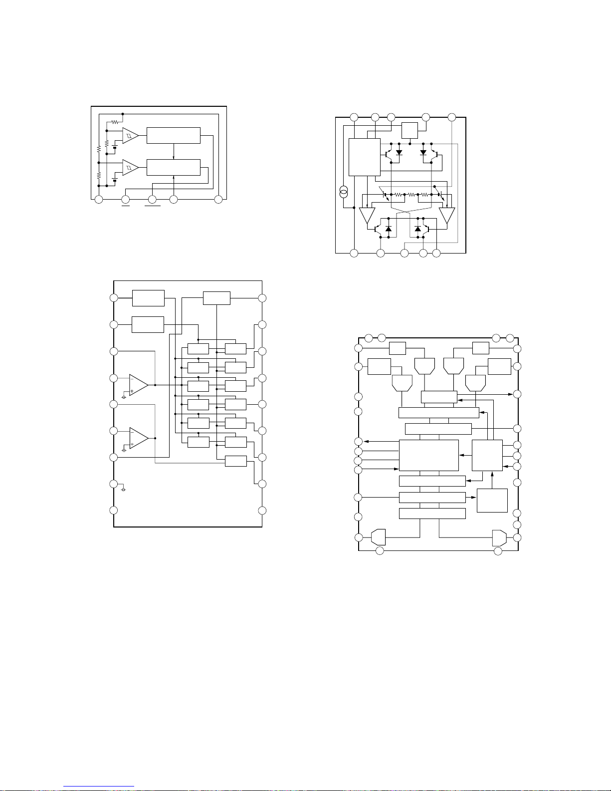
– 111 –
• PANEL (1/2) Board
IC603 BA3830F
• MAIN (3/4) Board
IC371 M62016L
1
2 3
4
5
+
–
INTERRUPT SIGNAL
GENERATING BLOCK
RESET SIGNAL
GENERATING BLOCK
+
–
GND INT RESET CD VCC
COM
COM
1
LOGIC
PREDRIVER
VREF
2 3
4
5
10 9 8 7 6
IN2 IN1 VM VREF VCONT
VCC OUT2 GND OUT1 VS
3
4
5
6
2
8
7
1
VADCN
VADCP
VINL2
PGA PGA
0DB/6DB
SWITCH
NOISE SHAPER
INTERPOLATION FILTER
DSP FEATURES
PRAK
DETECTOR
L3-BUS
INTERFACE
DECIMATION FILTER
DIGITAL
INTERFACE
DIGITAL MIXER
DIGITAL AGC
ADC1L
ADC2L
ADC2R
ADC1R
DAC
DAC
0DB/6DB
SWITCH
VSS(AD)
VDD(AD)
VINL1
VDDD
VSSD
18
16
19
17
26
25
27
24
13
15
14
9
22
10
11
23
28
12
20
21
DATAO
BCK
WS
DATAI
QMUTE
VREF
VOUTL
DD(DAC)
VSS(DAC)
VOUTR
TEST2
TEST1
SYSCLK
L3DATA
L3MODE
L3CLOCK
OVERFLOW
AGCSTAT
VINR1
VINR2
• MD DIGITAL Board
IC153 LB1830M-S-TE-L
IC201 UDA1341TS
2
3
14
1
f04
13
f05
12
f06
11
REC
LEVEL
10
VCC
15
f03
5
REC
NF
6
REC
IN
7
RESET
C
8
BIAS
C
9
GND1
4
16
f02
17
f01
18
RESET
R02
P01
LINE
NF
LINE
IN
REFFERENCE
CURRENT
BPF
DET
BPF
DET
BPF
DET
BPF
DET
DET
RESET
Bias
REFFERENCE
CURRENT
DET
DET
BPF
BPF
Page 76
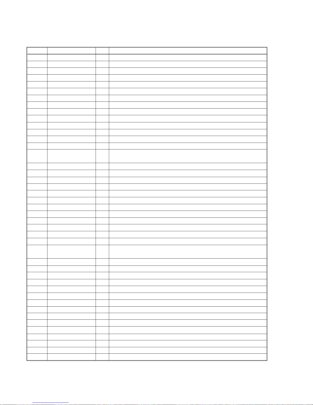
– 112 –
8-32. IC PIN FUNCTIONS
• IC101 RF Amplifier (CXA2523AR) (BD (MD) board)
Pin No.
Pin Name I/O Function
I
J
VC
A to F
PD
APC
APCREF
GND
TEMPI
TEMPR
SWDT
SCLK
XLAT
XSTBY
F0CNT
VREF
EQADJ
3TADJ
Vcc
WBLADJ
TE
CSLED
SE
ADFM
ADIN
ADAGC
ADFG
AUX
FE
ABCD
BOTM
PEAK
RF
RF AGC
AGCI
COMPO
COMPP
ADDC
OPO
OPN
RFO
MORFI
MORFO
I
I
O
I
I
O
I
—
I
O
I
I
I
I
I
O
I/O
I/O
—
I/O
O
—
O
O
I
—
O
O
O
O
O
O
O
—
I
O
I
I/O
O
I
O
I
O
I-V converted RF signal I input
I-V converted RF signal J input
Middle point voltage (+1.5V) generation output
Signal input from the optical pick-up detector
Light amount monitor input
Laser APC output
Reference voltage input for setting laser power
Ground
Temperature sensor connection
Reference voltage output for the temperature sensor
Serial data input from the CXD2650R or CXD2652AR
Serial clock input from the CXD2650R or CXD2652AR
Latch signal input from the CXD2650R or CXD2652AR “L”: Latch
Stand by signal input “L”: Stand by
Center frequency control voltage input of BPF22, BPF3T, EQ from the CXD2650R or
CXD2652AR
Reference voltage output (Not used)
Center frequency setting pin for the internal circuit EQ
Center frequency setting pin for the internal circuit BPF3T
+3V power supply
Center frequency setting pin for the internal circuit BPF22
Tracking error signal output to the CXD2650R or CXD2652AR
External capacitor connection pin for the sled error signal LPF
Sled error signal output to the CXD2650R or CXD2652AR
FM signal output of ADIP
ADIP signal comparator input ADFM is connected with AC coupling
External capacitor connection pin for AGC of ADIP
ADIP duplex signal output to the CXD2650R or CXD2652AR
I
3 signal/temperature signal output to the CXD2650R or CXD2652AR
(Switching with a serial command)
Focus error signal output to the CXD2650R or CXD2652AR
Light amount signal output to the CXD2650R or CXD2652AR
RF/ABCD bottom hold signal output to the CXD2650R or CXD2652AR
RF/ABCD peak hold signal output to the CXD2650R or CXD2652AR
RF equalizer output to the CXD2650R or CXD2652AR
External capacitor connection pin for the RF AGC circuit
Input to the RF AGC circuit The RF amplifier output is input with AC coupling
User comparator output (Not used)
User comparator input (Fixed at “L”)
External capacitor pin for cutting the low band of the ADIP amplifier
User operation amplifier output (Not used)
User operation amplifier inversion input (Fixed at “L”)
RF amplifier output
Groove RF signal is input with AC coupling
Groove RF signal output
1
2
3
4 to 9
10
11
12
13
14
15
16
17
18
19
20
21
22
23
24
25
26
27
28
29
30
31
32
33
34
35
36
37
38
39
40
41
42
43
44
45
46
47
48
• Abbreviation
APC: Auto Power Control
AGC: Auto Gain Control
Page 77
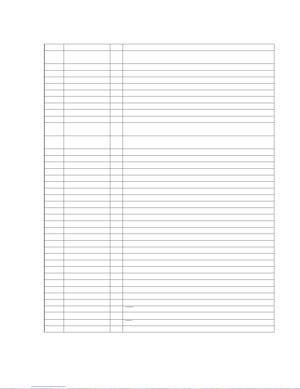
– 113 –
1
2
3
4
5
6
7
8
9
10
11
12
13
14
15
16
17
18
19
20
21
22
23
24
25
26
27
28
29
30
31 to 34
35
36 to 40
41
42
43
44
45
46
47
• IC121 Digital Signal Processor, Digital Servo Signal Processor, EFM/ACIRC Encoder/Decoder,
Shock-proof Memory Controller, ATRAC Encoder/Decoder, 2M Bit DRAM (CXD2654R) (BD (MD) board)
Function
Pin No.
Pin Name I/O
MNT0 (FOK)
MNT1 (SHCK)
MNT2 (XBUSY)
MNT3 (SLOC)
SWDT
SCLK
XLAT
SRDT
SENS
XRST
SQSY
DQSY
RECP
XINT
TX
OSCI
OSCO
XTSL
DIN0
DIN1
DOUT
DADTI
LRCKI
XBCKI
ADDT
DADT
LRCK
XBCK
FS256
DVDD
A03 to A00
A10
A04 to A08
A11
DVSS
XOE
XCAS
A09
XRAS
XWE
O
O
O
O
I
I (S)
I (S)
O (3)
O (3)
I (S)
O
O
I
O
I
I
O
I
I
I
O
I
I
I
I
O
O
O
O
—
O
O
O
O
—
O
O
O
O
O
FOK signal output to the system control (monitor output)
“H” is output when focus is on
Track jump detection signal output to the system control (monitor output)
Monitor 2 output to the system control (monitor output)
Monitor 3 output to the system control (monitor output)
Writing data signal input from the system control
Serial clock signal input from the system control
Serial latch signal input from the system control
Reading data signal output to the system control
Internal status (SENSE) output to the system control
Reset signal input from the system control “L”: Reset
Subcode Q sync (SCOR) output to the system control
“L” is output every 13.3 msec. Almost all, “H” is output
Digital In U-bit CD format or MD format subcode Q sync (SCOR) output to the system
control
Laser power switching input from the system control “H”: Recording, “L”: Playback
Interrupt status output to the system control
Recording data output enable input from the system control
System clock input (512Fs=22.5792 MHz)
System clock output (512Fs=22.5792 MHz) (Not used)
System clock frequency setting “L”: 45.1584 MHz, “H”: 22.5792 MHz (Fixed at “H”)
Digital audio input (Optical input)
Digital audio input (Optical input)
Digital audio output (Optical output)
Serial data input
LR clock input “H” : Lch, “L” : R ch
Serial data clock input
Data input from the A/D converter
Data output to the D/A converter
LR clock output for the A/D and D/A converter (44.1 kHz)
Bit clock output to the A/D and D/A converter (2.8224 MHz)
11.2896 MHz clock output (Not used)
+3V power supply (Digital)
DRAM address output
DRAM address output (Not used)
DRAM address output
DRAM address output (Not used)
Ground (Digital)
Output enable output for DRAM
CAS signal output for DRAM
Address output for DRAM
RAS signal output for DRAM
Write enable signal output for DRAM (Used : CXD2652AR, Not used : CXD2650R)
* I (S) stands for Schmidt input, I (A) for analog input, O (3) for 3-state output, and O (A) for analog output in the column I/O
Page 78

– 114 –
Function
Pin No.
Pin Name I/O
48
49
50, 51
52
53
54
55
56
57
58
59
60
61
62
63
64
65
66
67
68
69
70
71
72
73
74
75
76
77
78
79
80
81
82
83
84
85
D1
D0
D2, D3
MVCI
ASYO
ASYI
AVDD
BIAS
RFI
AVSS
PCO
FILI
FILO
CLTV
PEAK
BOTM
ABCD
FE
AUX1
VC
ADIO
AVDD
ADRT
ADRB
AVSS
SE
TE
DCHG
APC
ADFG
F0CNT
XLRF
CKRF
DTRF
APCREF
TEST0
TRDR
Data input/output for DRAM
Clock input from an external VCO (Fixed at “L”)
Playback EFM duplex signal output
Playback EFM comparator slice level input
+3V power supply (Analog)
Playback EFM comparator bias current input
Playback EFM RF signal input
Ground (Analog)
Phase comparison output for the recording/playback EFM master PLL
Filter input for the recording/playback EFM master PLL
Filter output for the recording/playback EFM master PLL
Internal VCO control voltage input for the recording/playback EFM master PLL
Light amount signal peak hold input from the CXA2523R
Light amount signal bottom hold input from the CXA2523R
Light amount signal input from the CXA2523R
Focus error signal input from the CXA2523R
Auxiliary A/D input
Middle point voltage (+1.5V) input from the CXA2523R
Monitor output of the A/D converter input signal (Not used)
+3V power supply (Analog)
A/D converter operational range upper limit voltage input (Fixed at “H”)
A/D converter operational range lower limit voltage input (Fixed at “L”)
Ground (Analog)
Sled error signal input from the CXA2523R
Tracking error signal input from the CXA2523R
Connected to +3V power supply
Error signal input for the laser digital APC (Fixed at “L”)
ADIP duplex FM signal input from the CXA2523R (22.05 ± 1 kHz)
Filter f
0 control output to the CXA2523R
Control latch output to the CXA2523R
Control clock output to the CXA2523R
Control data output to the CXA2523R
Reference PWM output for the laser APC
PWM output for the laser digital APC (Not used)
Tracking servo drive PWM output (–)
I/O
I/O
I/O
I (S)
O
I (A)
—
I (A)
I (A)
—
O (3)
I (A)
O (A)
I (A)
I (A)
I (A)
I (A)
I (A)
I (A)
I (A)
O (A)
—
I (A)
I (A)
—
I (A)
I (A)
I (A)
I (A)
I (S)
O
O
O
O
O
O
O
• Abbreviation
EFM: Eight to Fourteen Modulation
PLL : Phase Locked Loop
VCO: Voltage Controlled Oscillator
Page 79
– 115 –
Function
Pin No.
Pin Name I/O
86
87
88
89
90
91
92
93
94
95
96 to 98
99
100
TFDR
DVDD
FFDR
FRDR
FS4
SRDR
SFDR
SPRD
SPFD
FGIN
TEST1 to TEST3
DVSS
EFMO
O
—
O
O
O
O
O
O
O
I (S)
I
—
O
Tracking servo drive PWM output (+)
+3V power supply (Digital)
Focus servo drive PWM output (+)
Focus servo drive PWM output (–)
176.4 kHz clock signal output (X’tal) (Not used)
Sled servo drive PWM output (–)
Sled servo drive PWM output (+)
Spindle servo drive PWM output (–)
Spindle servo drive PWM output (+)
Test input (Fixed at “L”)
Ground (Digital)
EFM output when recording
• Abbreviation
EFM: Eight to Fourteen Modulation
Page 80
– 116 –
• IC501 MASTER CONTROL (M30620MC-A03FP) (MAIN board (4/4))
Pin No.
Pin Name I/O Function
1 STK-MUTE O Power amp ON/OFF signal output
2 POWER O Power ON/OFF signal output
3 F-RELAY O Front speaker relay control output
4 REAR-RELAY O Rear speaker relay control output (Not used)
5 CD-POWER O CD power on signal output
6 LINE-MUTE O Line mute ON/OFF selection output
7 DBFB-H/L O DBFB H/L select signal output
8, 9 – – Not used
10 XC-IN I
11 XC-OUT O
12 RESET I Reset signal input
13 X-OUT O X’tal (16MHz)
14 VSS – Ground
15 X-IN I X’tal (16MHz)
16 VCC – Power supply (+5V)
17 NMI I Not used (PULL UP EVER+5V)
18 W AKE UP I WAKE UP (Fixed at fixed at “L”)
19 SCOR I Subcode data request signal output
20 RDS-INT I
21 RDS-DATA I
22 AC-CUT I Back up signal input
23 PL-CLK O Clock signal to pro-logic (Not used)
24 PL-DATA O Data signal to pro-logic (Not used)
25 PL-LAT O Latch signal to pro-logic (Not used)
26 TIMER LED I Timer LED ON/OF
27 PROTECTOR ON I Speaker protect ON/OF
28 – – Not used
29 IIC-CLK O Clock output for IC601
30 IIC-DATA O Data output for IC601
31 – – Not used
32 SQ-DATA I
33 SQ-CLK I
34 SW-MODE O Not used
35 CD-DATA O CD data output
36 HP DET I Head phone swich detect
37 CD-CLK O CD clock output
38 493-LAT O Latch signal output for M62493FP (IC101)
ST-BY LED/
CLOCK-OUT
40 L+R/L-R I
41 BY-PASS I
42 FL-SW I FL switch ON/OFF
43 STBY RELAY I Stand by relay ON/OFF
44 HIGH/LOW FRQ O FREQ high/low signal for SYNC bass
45 – – Not used
46 D-IN SEL I Digital input selector
47 493-DATA O Data output for M62493FP (IC101)
48 493-CLK O Clock output for M62493FP (IC101)
49 ST-MUTE O Tuned mute signal output
X’tal (32.768MHz)
RDS data interrupt input
Subcode Q data clock input
39
O Clock ond stand by LED signal output
Not used
Page 81

– 117 –
Pin No.
Pin Name
I/O Function
50 STEREO I Stereo detection for tuner
51 TUNED I Tuned detection for tuner
52 ST-CE O Tuner chip enable output
53 ST-DOUT O Tuner data output
54 ST-DIN I Tuner data input
55 ST-CLK O Tuned clock output
56 SENS I BD Condition signal input
57 HDLD O Mode hold signal output
58 XLAT O CD latch signal output
59 XRST O CD reset signal output
60 DISC-SENS I Slit sensor of disc table input
61 T-SENS I CD table detection signal input
62 VCC – Power supply (+5V)
63 TBL-L O Table motor control output
64 VSS – Ground
65 TBL-R O Table motor control output
66 LOAD-OUT O
67 LOAD-IN O
68 ENC 3/UP-SW I
69 ENC 2/DISC-LED I
70 ENC 1 I
71 OUT-OPEN O Loading out detection signal output
72 B-TRG O
73 A-TRG O
74 CAP-M-COT2 O Capstan motor control 1(-) signal output
75 CAP-M-COT1 O Capstan motor control 2(-) signal output
76 CAP-M-H/L O Capstan motor H/L speed select signal output
77 AMS-IN I Connected to ground
78 TC-MUTE O TC mute ON/OFF selection output
79 R/PB/PAS O REC/PB/PASS selection output
80 NR-ON/OFF O NR ON/OFF signal output
81 REC-MUTE O REC mute ON/OFF selection output
82 BIAS O Bias ON/OFF selection output
83 EQ-H/N O Equalizer H/N select output
84 PB-A/B O PB Deck A/Deck B select output
85 ALC O ALC ON/OFF output
86 B-PLAY-SW I Deck B play detect
87 A-PLAY-SW I Deck A play detect
88 A-HALF I Deck A cassette detect
89 B-HALF I Deck B cassette detect
90 B-SHUT I B Deck reel pulse detector
91 A-SHUT I A Deck reel pulse detector
92 SOFT-TEST O Software test port
93, 94 KEY/CD-ADJ I CD adjust point port
95 MODEL IN I Version select signal input
96 AVSS – Ground
97 SPEC-IN I Version select signal input
98 VREF I Analog reference voltage input
99 AVCC – Analog power supply
100 TC-RELAY O REC/PB head selection output for IC602
Loading motor control signal output
Disc tray address detect encoder input
Trigger motor control output
Page 82

– 118 –
• IC601 DISPLAY CONTROL (TMP88CS77F-6003) (DISPLAY board)
Pin No.
Pin Name I/O Function
1 JOG A I Rotary encoder (S601) pulse input
2 to 4 LED O LED switch signal
5 WAKE UP O WAKE UP signal
6 to 8 LED O LED switch signal
9 L SEL O LED select signal
10 JOG B I Rotary encoder (S601) pulse input
11, 12 VOL A, VOL B I Rotary encoder (S602) pulse input
13 to 15 DISC 3 LED to O LED switch signal
DISC 1 LED
16 MD LED O LED switch signal
17 to 20 KEY 3 to KEY 0 I Key input
21 MD REC R O MD REC R signal
22 S LOW (F01) O Sptctrum analyzer input (Super low flegency) (40Hz)
23 BPF 1 (F02) O Sptctrum analyzer input (100Hz)
24 BBF 2 O Sptctrum analyzer input (400Hz)
25 BBF 3 O Sptctrum analyzer input (2KHz)
26 BBF 4 O Sptctrum analyzer input (6KHz)
27 ALL B (L+R) I Sptctrum analyzer input (all band)
28 MD REC L O MD REC L signal
29 VSS I/O – Ground
30 VASS – Ground
31 VA ref I Analog reference voltage input
32 VDD I/O – Power supply (+5V)
33 to 50 G18 to G1 O FL gride signal output
51 VDD FV7 – Power supply (+5V)
52 to 86 S1 to S35 O FL segment signal output
87 VKK – Power supply (-30V)
88 VDD for CPU – Power supply (+5V)
89 X IN I X’tal (12.5MHz)
90 VSS for CPU – Ground
91 X OUT O X’tal (12.5MHz)
92 Reset I Reset signal input from main controller
93, 94 LED O LED switch signal
95 TAST I Connected ground
96 LED O LED switch signal
97 I2C DATA O Data output for IC501
98 I2C CLK O Clock output for IC501
99 LED O LED switch signal
100 SIRCS I Remote commander signal input
Page 83
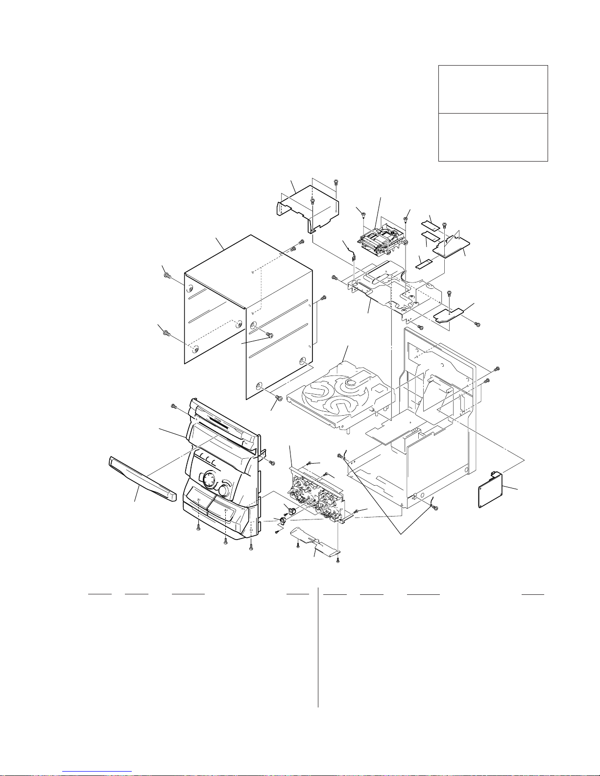
– 119 –
SECTION 9
EXPLODED VIEWS
9-1. CASE SECTION
NOTE:
• Items marked “*” are not stocked since they are
seldom required for routine service. Some delay
should be anticipated when ordering these items.
• The mechanical parts with no reference number in
the exploded views are not supplied.
• Hardware (# mark) list and accessories and packing materials are given in the last of this parts list.
• Abbreviation
CND : Canadian model
G : German model
SP : Singapore model
MY : Malaysia model
AR : Argentine model
KR : Korean model
AUS : Australian model
Ref. No. Part No. Description Remark
Ref. No. Part No. Description Remark
1 X-4951-202-1 LOADING PANEL ASSY
2 3-363-099-71 SCREW (CASE 3 TP2)
3 3-363-099-11 SCREW (CASE 3 TP2)
4 4-216-858-01 CASE
5 4-215-062-01 DAMPER
6 4-951-620-01 SCREW (2.6x8), +BVTP
7 4-999-839-11 SCREW (+BVTTWH M3), STEP
8 1-775-102-11 WIRE (FLAT TYPE) (11 CORE)
9 1-775-192-11 WIRE (FLAT TYPE) (21 CORE) (150mm)
10 1-775-208-11 WIRE (FLAT TYPE) (23 CORE) (140mm)
4
2
2
3
1
3
13
#12
#2
#2
#2
#2
#2
#2
#12
#12
#12
#12
#12
CDM38LH-5BD32L
MDM-5A
Front panel
#12
#1
#1
#1
not supplied
not supplied
7
8
9
10
11
12
7
6
6
not supplied
not supplied
6
5
5
#5
#5
#11
#11
TCM230AWR2
TCM230PWR2
#2
#1
#1
Including Panel board
(Ref No. 119)
11 A-4419-305-A MD DIGITAL BOARD, COMPLETE
12 A-4419-326-A MD LINK BOARD, COMPLETE (AEP,UK,G,CIS)
12 A-4419-499-A MD LINK BOARD, COMPLETE
(EXCEPT AEP,UK,G,CIS)
13 1-233-544-14 ENCAPSULATED COMPONENT (US,CND)
13 1-233-545-14 ENCAPSULATED COMPONENT (AR,KR,AUS)
13 1-233-546-13 ENCAPSULATED COMPONENT (SP,MY,HK)
13 1-693-443-11 TUNER UNIT (FM/AM) (AEP,UK,G,CIS)
13 1-693-453-11 TUNER UNIT (FM/AM) (E)
The components identified by
mark ! or dotted line with mark
! are critical for safety.
Replace only with part number
specified.
Les composants identifiés par une
marque ! sont critiques pour la
sécurité.
Ne les remplacer que par une
piéce portant le numéro spécifié.
Page 84
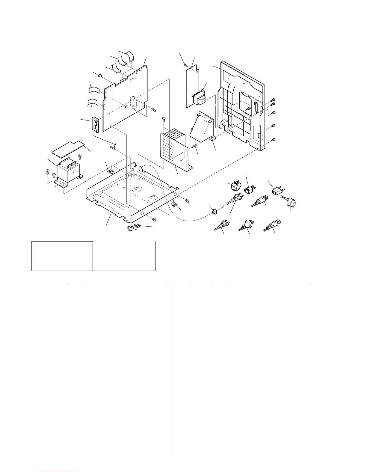
– 120 –
9-2. CHASSIS SECTION
Ref. No. Part No. Description Remark Ref. No. Part No. Description Remark
51 4-965-822-01 FOOT
52 1-673-377-11 SECONDARY BOARD
53 A-4405-868-A MAIN BOARD, COMPLETE (AEP,UK,G,CIS)
53 A-4405-869-A MAIN BOARD, COMPLETE (SP,MY,HK)
53 A-4405-871-A MAIN BOARD, COMPLETE (E,AR)
53 A-4405-872-A MAIN BOARD, COMPLETE (AUS)
53 A-4405-873-A MAIN BOARD, COMPLETE (KR)
53 A-4405-875-A MAIN BOARD, COMPLETE (US,CND)
54 1-773-043-11 WIRE (FLAT TYPE) (17 CORE)
55 1-773-025-11 WIRE (FLAT TYPE) (15 CORE) (330mm)
56 1-769-976-11 WIRE (FLAT TYPE) (13 CORE)
(US,CND,E,AR,KR,AUS)
56 1-773-008-11 WIRE (FLAT TYPE) (15 CORE) (140mm)
(AEP,UK,G,CIS,SP,MY,HK)
57 1-773-185-11 WIRE (FLAT TYPE) (23 CORE)
* 58 3-703-244-00 BUSHING (2104), CORD (EXCEPT E)
58 3-703-571-11 BUSHING (S) (4516), CORD (E)
59 1-569-007-11 ADAPTOR, CONVERSION 2P (E)
59 1-569-008-21 ADAPTOR, CONVERSION 2P (SP,MY)
59 1-770-019-11 ADAPTOR, CONVERSION PLUG 3P (HK)
! 60 1-696-845-11 CORD, POWER (AUS)
! 60 1-769-079-11 CORD, POWER (KR)
! 60 1-777-071-41 CORD, POWER (AEP,G,CIS,SP,MY)
! 60 1-777-514-11 CORD, POWER (UK)
! 60 1-782-315-21 CORD, POWER (E)
!60 1-783-820-21 CORD, POWER (US,CND)
60
(AUS)
60
(US,CND)
60
(AR)
52
66
53
62
64
56
57
67
55
65
54
58
61
#2
#2
T951
T11
not supplied
Including Secondary board
(Ref No. 52)
63
68
not supplied
not supplied
#2
#1
#1
#1
51
66
66
59
(SP,MY)
59
(HK)
59
(E)
60
(AEP,G,CIS,SP,MY,KR)
60
(UK)
60
(E)
#2
#12
#12
#12
#6
#12
#12
#2
! 60 1-783-941-31 CORD, POWER (AR)
61 X-4951-203-1 BACK PANEL ASSY (AEP,UK,G,CIS)
61 X-4951-205-1 BACK PANEL ASSY (E,SP,MY,HK,AR)
61 X-4951-207-1 BACK PANEL ASSY (US,CND,KR,AUS)
62 A-4419-327-A STANDBY BOARD, COMPLETE (AEP,UK,G,CIS)
62 A-4419-328-A STANDBY BOARD, COMPLETE (E,SP,MY,HK,AR)
62 A-4419-329-A STANDBY BOARD, COMPLETE (US,CND)
62 A-4419-330-A STANDBY BOARD, COMPLETE (AUS)
62 A-4419-651-A STANDBY BOARD, COMPLETE (KR)
63 4-216-856-01 DUCT
64 4-951-620-01 SCREW (2.6X8), +BVTP
65 1-569-972-21 SOCKET, SHORT 2P
66 4-216-857-01 COVER (LIZ)
67 1-783-570-11 WIRE (FLAT TYPE)(19 CORE)
68 4-221-078-01 SCREW +BSW 3X20 (S)
!T11 1-433-832-11 TRANSFORMER, POWER
(E,SP,MY,HK,AR,KR,AUS)
!T11 1-433-833-11 TRANSFORMER, POWER (AEP,UK,G,CIS)
!T11 1-433-835-11 TRANSFORMER, POWER (US,CND)
!T951 1-433-790-11 TRANSFORMER, POWER (CND)
!T951 1-433-791-11 TRANSFORMER, POWER (AEP,UK,G,CIS)
!T951 1-433-792-11 TRANSFORMER, POWER (US)
!T951 1-433-793-11 TRANSFORMER, POWER (KR)
!T951 1-433-794-11 TRANSFORMER, POWER (E,SP,MY,HK,AR,AUS)
Les composants identifiés par une
marque ! sont critiques pour la
sécurité.
Ne les remplacer que par une
piéce portant le numéro spécifié.
The components identified by
mark ! or dotted line with mark
! are critical for safety.
Replace only with part number
specified.
Page 85
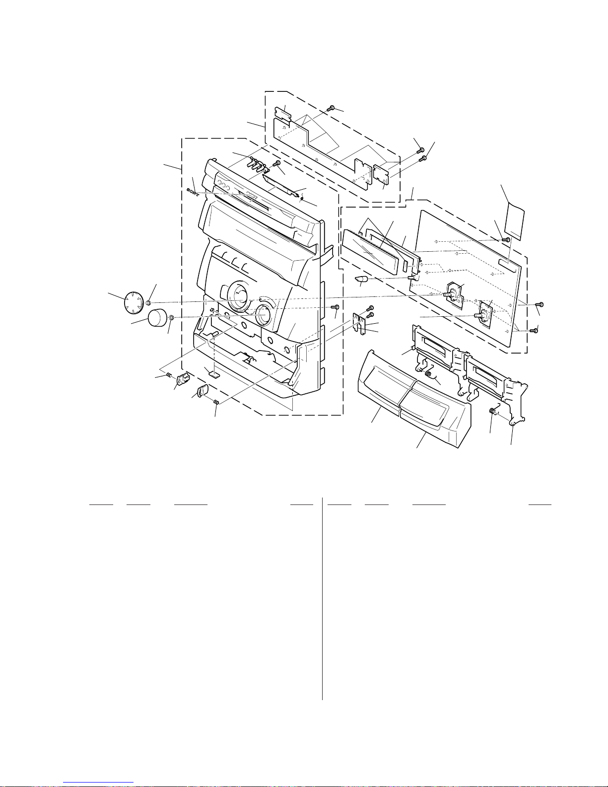
– 121 –
9-3. FRONT PANEL SECTION
117
112
121
FL601
#2
#2
not supplied
not supplied
117
127
128
Supplied with
S601
Supplied with
S602
105
105
109
111
114
113
108
101
106
107
110
103
102
104
118
124
119
117
122
120
117
117
123
117
115
116
117
125
126
Ref. No. Part No. Description Remark Ref. No. Part No. Description Remark
101 X-4951-200-1 CASSETTE LID (A) ASSY
102 X-4951-201-1 CASSETTE LID (B) ASSY
103 X-4951-198-1 CASSETTE HOLDER (A) ASSY
104 X-4951-199-1 CASSETTE HOLDER (B) ASSY
105 4-214-775-11 SPRING, PUSH CATCHER RETURN
106 4-214-760-11 CATCHER (A), PUSH
107 4-214-761-11 CATCHER (B), PUSH
108 4-214-384-11 KNOB (VOL)
109 4-214-383-11 KNOB (JOG)
110 4-930-336-61 FOOT (FELT)
111 4-216-415-01 SPRING (L)
112 4-216-416-01 SPRING (R)
113 X-4951-197-1 FRONT PANEL ASSY (AEP,UK,G,CIS)
113 X-4951-204-1 FRONT PANEL ASSY (EXCEPT AEP,UK,G,CIS)
114 4-962-708-71 EMBLEM (4-A), SONY
115 4-216-729-41 LID (CARTRIDGE)
116 4-976-593-11 SPRING (LID), TORSION
117 4-951-620-01 SCREW (2.6X8), +BVTP
118 A-4419-498-A CD PANEL BOARD, COMPLETE
(EXCEPT AEP,UK,G,CIS)
118 A-4419-325-A CD PANEL BOARD, COMPLETE (AEP,UK,G,CIS)
119 A-4419-324-A DISPLAY BOARD, COMPLETE (AEP,UK,G,CIS)
119 A-4419-497-A DISPLAY BOARD, COMPLETE
(EXCEPT AEP,UK,G,CIS)
* 120 4-214-439-11 HOLDER, FL TUBE
121 4-214-385-81 KNOB (MIC)
122 1-675-345-11 WIRE (FLAT TYPE)(23 CORE)
123 1-673-382-11 MD LINK SW BOARD
124 1-673-381-11 POWER SW BOARD
125 1-673-837-21 TC STOPPER A BOARD
126 1-673-838-21 TC STOPPER B BOARD
127 1-673-379-11 JOG BOARD
128 1-673-380-11 VOL BOARD
FL601 1-517-841-11 INDICATOR TUBE, FLUORESCENT
Page 86
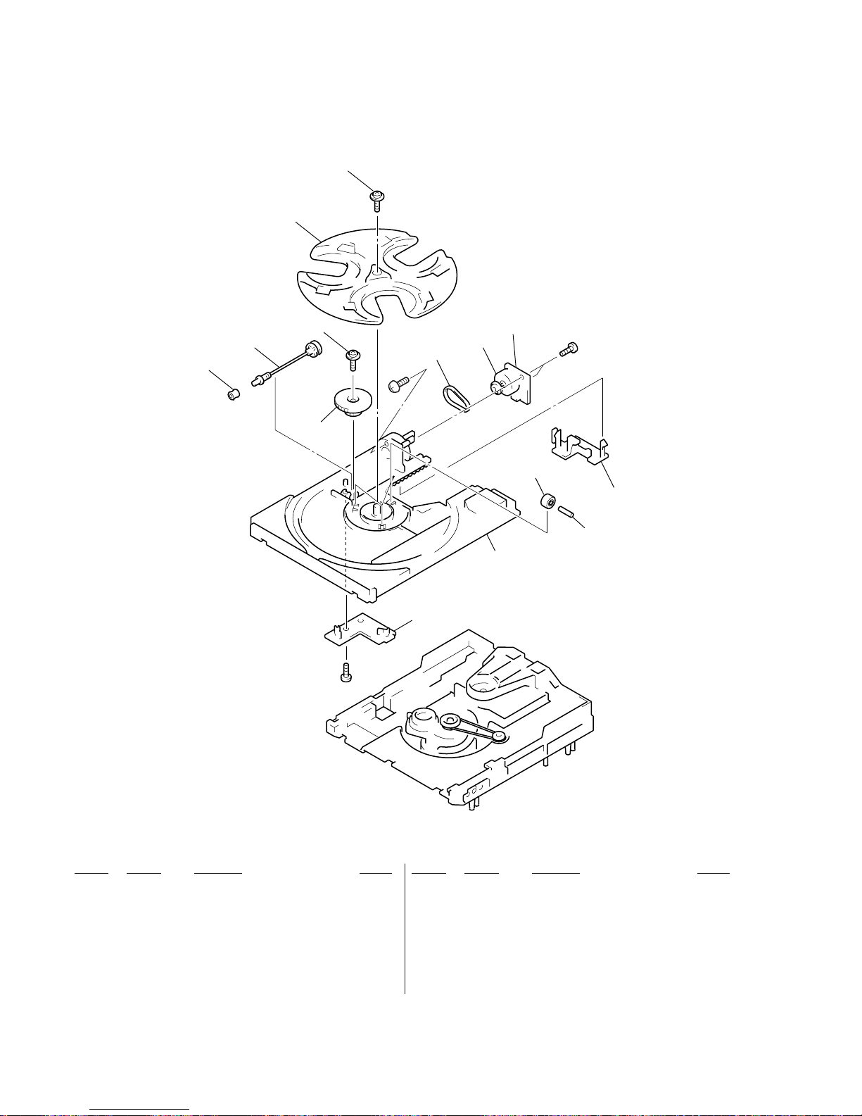
– 122 –
9-4. CD MECHANISM DECK SECTION-1 (CDM38LH-5BD32L)
Ref. No. Part No. Description Remark Ref. No. Part No. Description Remark
207 4-988-162-01 ROLLER
208 4-977-941-01 BEARING (WORM)
* 209 1-658-576-11 SENSOR BOARD
210 4-934-376-01 SHAFT (ROLLER)
211 4-981-187-01 COLLAR (WORM)
212 4-977-944-01 TRAY (SLIDE)
M701 A-4672-004-A MOTOR ASSY (TURN)
201 4-981-789-01 BRACKET, YOKE
202 4-977-945-01 TRAY (TURN)
203 X-4946-665-1 SHAFT ASSY, WORM
204 4-977-943-01 BELT (TURN) (1.2)
205 4-977-956-01 WHEEL, WORM
* 206 1-658-577-11 MOTOR (TURN) BOARD
#6
M701
#2
#2
201
201
202
203
211
204
205
206
208
209
210
207
212
Page 87
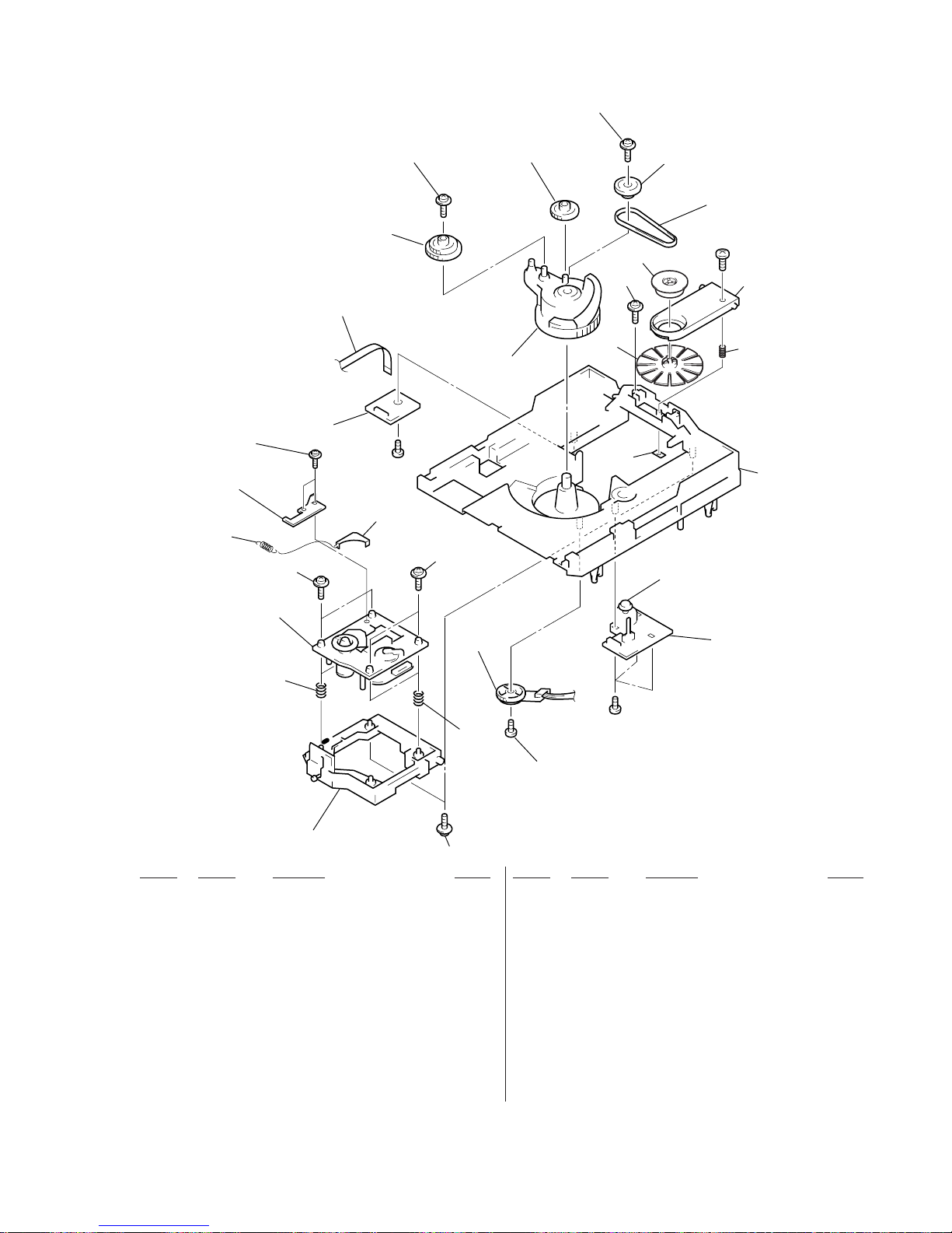
– 123 –
9-5. CD MECHANISM DECK SECTION-2 (CDM38LH-5BD32L)
Ref. No. Part No. Description Remark Ref. No. Part No. Description Remark
251 4-917-583-71 BRACKET, YOKE
252 4-977-954-01 PULLEY (SL)
253 4-977-953-01 GEAR (SL-A)
254 4-977-955-01 GEAR (SL-B)
255 4-977-942-01 BELT (SL) (1.4)
256 X-4946-667-1 CAM ASSY, BU
257 1-452-925-21 MAGNET ASSY
258 1-776-042-11 WIRE (FLAT TYPE) (8 CORE)
* 259 1-658-575-11 CONNECTOR BOARD
260 4-900-743-01 SPRING, COMPRESSION
261 4-985-672-01 SCREW (+PTPWHM2.6), FLOATING
* 262 1-658-578-11 MOTOR (SLIDE) BOARD
263 4-982-447-01 SPRING (BU), COMPRESSION
264 4-951-620-41 SCREW (2.6), +BVTP
265 X-4949-570-1 HOLDER (BU) ASSY
266 4-989-494-01 SCREW (SLIDER), STEP
267 4-989-492-11 SLIDER (38)
268 4-989-819-02 SPRING, TENSION
269 4-989-491-01 COVER, LENS
270 4-993-142-21 PULLEY (L), PRESS
* 271 4-900-718-01 BRACKET (ADJUSTMENT)
S811 1-473-335-11 ENCODER, ROTARY
M801 A-4672-004-A MOTOR ASSY (SLIDE)
251
251
251
252
253
254
255
257
251
270
256
258
259
260
271
261
261
BU-5BD32L
#2
#7
#2
S811
M801
not supplied
not supplied
262
263
264
265
263
266
269
268
267
Page 88
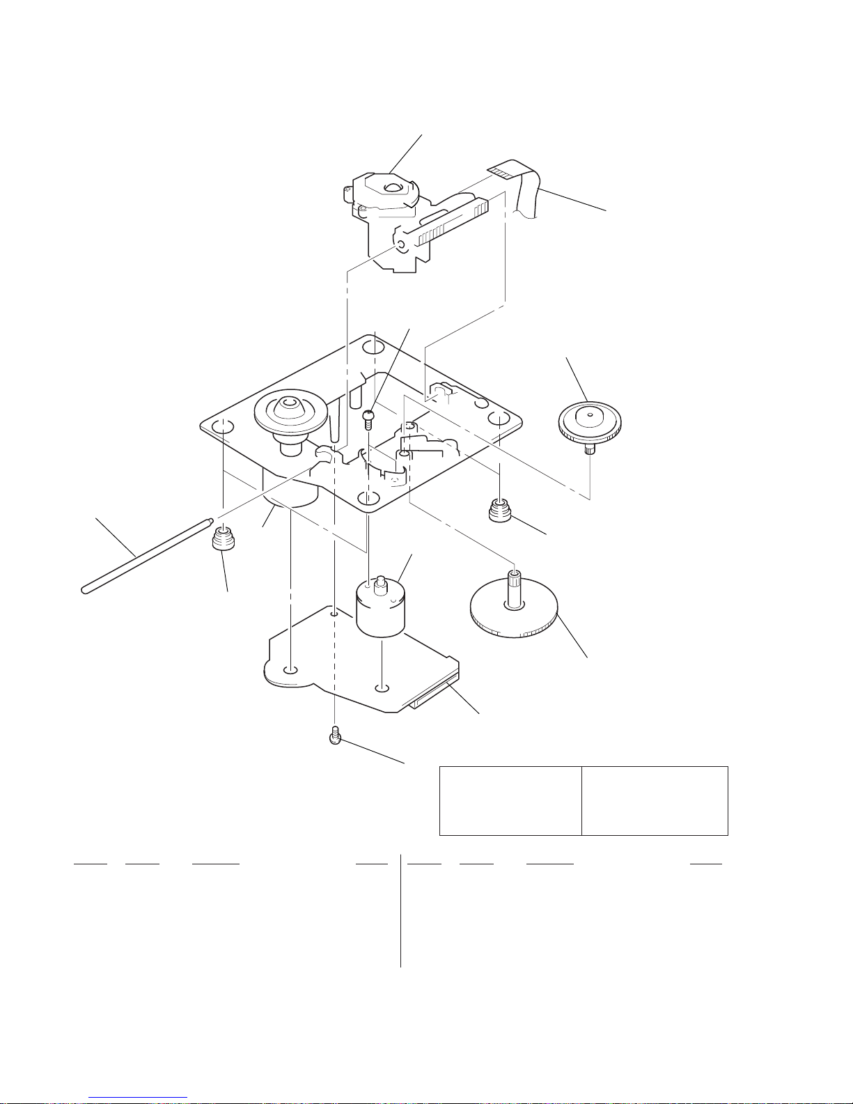
– 124 –
9-6. BASE UNIT SECTION (BU-5BD32L)
Ref. No. Part No. Description Remark Ref. No. Part No. Description Remark
! 301 8-820-020-02 OPTICAL PICK-UP KSS-213D/Q-NP
302 1-769-069-11 WIRE (FLAT TYPE) (16 CORE)
303 4-917-567-01 GEAR (M)
304 4-951-940-01 INSULATOR (BU)
305 4-917-565-01 SHAFT, SLED
306 4-917-564-01 GEAR (P), FLATNESS
* 307 A-4724-486-A BD (CD) BOARD, COMPLETE
308 4-951-620-01 SCREW (2.6X8), +BVTP
309 3-713-786-51 SCREW +P 2X3
M201 X-4917-523-3 MOTOR ASSY (SPINDLE)
M202 X-4917-504-1 MOTOR ASSY (SLED)
309
M202
M201
301
302
303
304
305
304
308
307
306
Les composants identifiés par une
marque ! sont critiques pour la
sécurité.
Ne les remplacer que par une
piéce portant le numéro spécifié.
The components identified by
mark ! or dotted line with mark
! are critical for safety.
Replace only with part number
specified.
Page 89
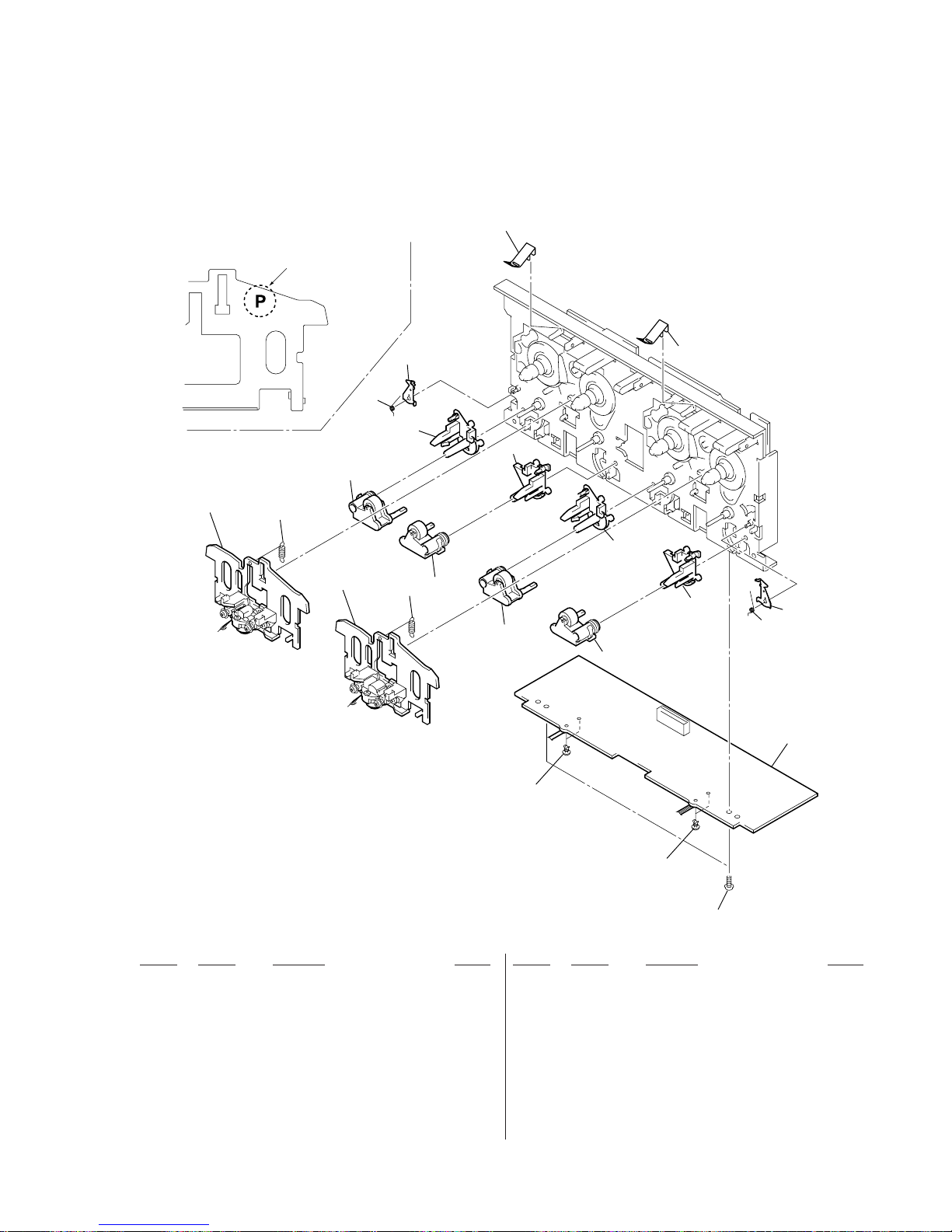
– 125 –
9-7. TC MECHANISM SECTION-1 (TCM230AWR2/230PWR2)
Ref. No. Part No. Description Remark Ref. No. Part No. Description Remark
401 3-376-464-11 SCREW(+PTT 2.6X6),GROUND POINT
402 3-911-116-21 RIVET, PUSH
403 3-016-574-11 SPRING (HEAD), TENSION
404 X-3374-156-4 PINCH LEVER (REV) ASSY
405 X-3374-155-4 PINCH LEVER (FWD) ASSY
406 3-016-564-01 BASE (PINCH LEVER FWD)
407 3-016-565-01 BASE (PINCH LEVER REV)
408 3-026-892-01 SPRING (CASSETTE), LEAF
* 409 A-2007-731-A AUDIO BOARD, COMPLETE
410 3-016-573-01 LEVER (EJECT PREVENTION R)
411 3-032-810-02 SPRING (R), TORSION
412 3-016-572-01 LEVER (EJECT PREVENTION L)
413 3-032-809-02 SPRING (L), TORSION
HP101 A-2056-681-A DECK (A) ASSY, HEAD (230AWR2)(*NOTE)
HP101A-2056-683-BDECK (A) ASSY, HEAD (230PWR2)(*NOTE)
HRPE101 A-2056-682-A DECK (B) ASSY, HEAD (230AWR2)(*NOTE)
HRPE101A-2056-684-BDECK (B) ASSY, HEAD (230PWR2)(*NOTE)
401
402
402
403
403
404
404
405
405
406
410
411
406
407
413
412
408
408
407
HRPE101
HP101
409
*NOTE: Two types of parts which are not interchangeable are available
for the Head deck (A) ASSY and Head deck (B) ASSY.
When replacing the parts, refer to the following figure, and use the
appropriate part.
Parts with “P” mark: 230PWR2
Parts without “P” mark: 230AWR2
Ver 1.1 2001.06
Page 90
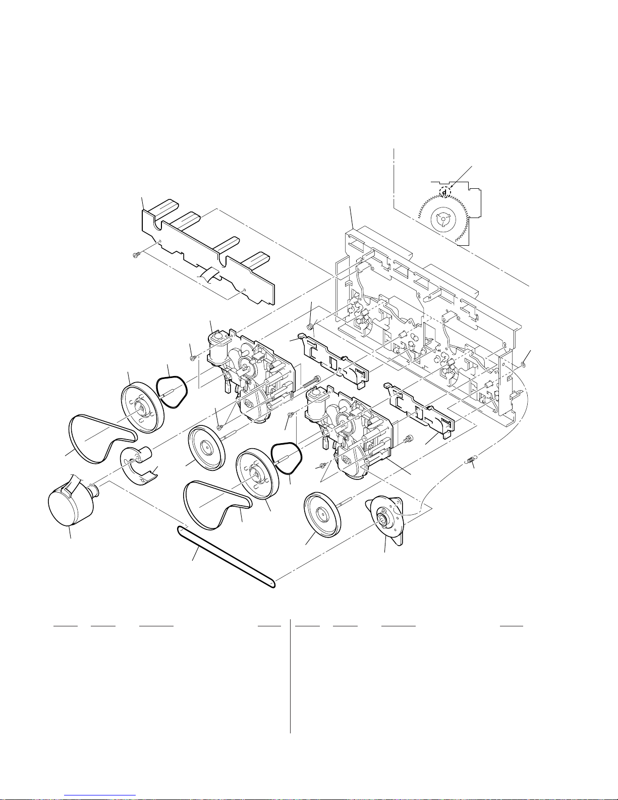
– 126 –
9-8. TC MECHANISM SECTION-2 (TCM230AWR2/230PWR2)
Ref. No. Part No. Description Remark Ref. No. Part No. Description Remark
* 451 X-3374-214-3 CHASSIS ASSY, MAIN
452 3-016-570-01 BELT (CAPSTAN)
453 3-016-569-01 BELT (TENSION)
454 3-017-360-01 BRACKET (MOTOR)
455 X-3376-497-1 FLYWHEEL (FWD) ASSY
456 X-3374-235-1 FLYWHEEL (REV) ASSY
457 X-3374-238-1 PULLEY ASSY, TENSION
458 3-024-405-01 BELT (FR2)
459 A-2004-629-A MECHANICAL BLOCK ASSY (230AWR2)(*NOTE)
459 A-2004-629-B MECHANICAL BLOCK ASSY (230PWR2)(*NOTE)
460 3-016-566-01 SLIDER, REVERSE
* 461 A-2007-732-A LEAF SW BOARD, COMPLETE
462 3-016-575-11 SPRING, TORSION
463 3-019-208-01 WASHER, STOPPER
464 3-027-453-01 SPRING (GROUND), TENSION
465 3-030-823-01 SCREW (+BVTT) (2X3.5)
M1 A-2004-628-A MOTOR ASSY, CAPSTAN
451
452
452
453
454
455
455
456
456
457
458
465
465
465
465
458
459
459
464
460
460
461
462
463
M1
#9
#10
#8
*NOTE: Two types of parts which are not interchangeable are available
for the mechanical block assembly. When replacing the parts,
refer to the following figure, and use the appropriate part.
Parts with “P” mark: 230PWR2
Parts without “P” mark: 230AWR2
Page 91
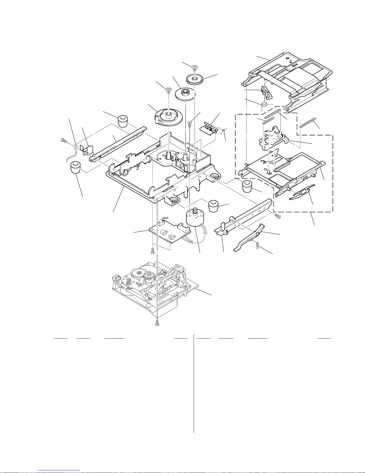
– 127 –
9-9. MD MECHANISM SECTION-1 (MDM-5A)
Ref. No. Part No. Description Remark Ref. No. Part No. Description Remark
515 4-996-227-01 LEVER (HEAD)
516 4-996-229-01 SPRING (HEAD LEVER), TORSION
517 4-996-212-01 LEVER (LIMITTER)
518 4-996-213-01 SPRING (LIMITTER), TORSION
519 4-996-214-01 SPRING (SLIDER), TENSION
520 4-966-216-01 SPRING (HOLDER), TENSION
521 4-996-215-11 SPRING (LOCK LEVER), TENSION
522 X-4949-246-1 SLIDER ASSY
523 X-4949-245-1 HOLDER ASSY
* 524 4-996-211-11 SLIDER (CAM)
525 4-998-763-01 SPRING (SHUTTER), LEAF
526 A-4680-409-A HOLDER
M103 X-4949-264-1 MOTOR ASSY, LOADING
* 501 1-671-115-21 SW BOARD
* 502 4-996-217-01 CHASSIS
503 4-996-223-11 INSULATOR (F)
* 504 4-996-218-01 BRACKET (GUIDE R)
505 4-996-277-01 SPRING (O/C), TENSION
506 4-996-226-01 LEVER (O/C)
507 4-999-347-01 INSULATOR (R)
* 508 4-996-225-01 BRACKET (GUIDE L)
509 4-988-466-11 SPRING (ELECTROSTATIC), LEAF
510 4-996-219-01 GEAR (CAM GEAR)
511 4-996-220-01 GEAR (A)
512 4-996-221-01 GEAR (B)
513 4-933-134-01 SCREW (+PTPWH M2.6X6)
514 4-996-224-01 SCREW (1.7X3), +PWH
#2
M103
#2
#2
not supplied
#3
MBU-5A
501
502
503
503
504
505
506
507
507
508
509
510
511
512
513
513
514
515
516
517
518
519
520
521
522
523
525
526
524
Page 92
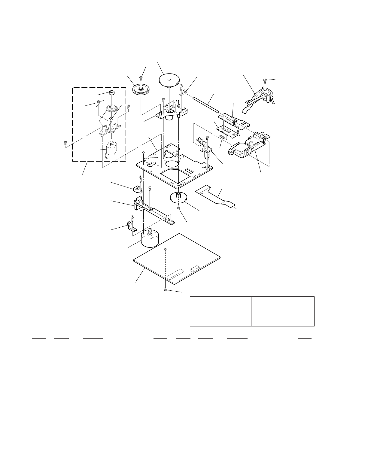
– 128 –
9-10. MD MECHANISM SECTION-2 (MDM-5A)
Ref. No. Part No. Description Remark Ref. No. Part No. Description Remark
551 A-4699-893-A BD (MD) BOARD, COMPLETE
552 3-372-761-01 SCREW (M1.7), TAPPING
* 553 4-996-267-01 BASE (BU-D)
* 554 4-996-255-01 BASE (BU-C)
555 4-900-590-01 SCREW, PRECISION SMALL
556 4-996-258-01 SPRING, COMPRESSION
557 4-996-262-01 GEAR (SL-C)
* 558 1-667-954-11 FLEXIBLE BOARD
* 559 4-210-664-11 BASE (BU-A)
! 560 8-583-028-01 OPTICAL PICK-UP KMS-260A/K1NP
* 561 4-996-252-01 CHASSIS, BU
* 562 4-996-254-01 BASE (BU-B)
563 4-967-688-11 MAGNET, ABSORPTION
Les composants identifiés par une
marque ! sont critiques pour la
sécurité.
Ne les remplacer que par une
piéce portant le numéro spécifié.
The components identified by
mark ! or dotted line with mark
! are critical for safety.
Replace only with part number
specified.
564 4-996-260-01 GEAR (SL-A)
565 4-996-261-01 GEAR (SL-B)
566 4-996-264-01 SPRING (SHAFT), LEAF
567 4-996-265-01 SHAFT, MAIN
568 4-996-256-11 SL (BASE)
569 4-996-257-01 RACK (SL)
570 4-996-263-01 SPRING (CLV), TORSION
571 4-988-560-01 SCREW (+P 1.7X6)
572 4-211-036-01 SCREW (1.7X2.5), +PWH
HR901 1-500-502-11 HEAD, OVER WRITE
M101 A-4672-475-A MOTOR ASSY, SPINDLE
M102 A-4672-474-A MOTOR ASSY, SLED
S102 1-762-148-21 SWITCH, PUSH (2 KEY)
not supplied
not supplied
#4
#4
HR901
#4
#4
#4
#4
#5
#5
#6
551
552
552
553
554
S102
M101
552
557
558
559
560
561
562
563
572
570
564
565
566
567
568
569
556
555
571
M102
Page 93

– 129 –
• CAPACITORS
uF : µ F
• COILS
uH : µ H
• Abbreviation
CND : Canadian model
G : German model
HK : Hong Kong model
SP : Singapore model
MY : Malaysia model
AUS : Australian model
AR : Argentine model
KR : Korean model
• Due to standardization, replacements in the parts list
may be different from the parts specified in the
diagrams or the components used on the set.
• -XX, -X mean standardized parts, so they may have
some difference from the original one.
• Items marked “*” are not stocked since they are
seldom required for routine service. Some delay
should be anticipated when ordering these items.
• RESISTORS
All resistors are in ohms
METAL: Metal-film resistor
METAL OXIDE: Metal Oxide-film resistor
F : nonflammable
• SEMICONDUCTORS
In each case, u: µ , for example:
uA...: µ A..., uPA...: µ PA..., uPB...: µ PB...,
uPC...: µ PC..., uPD...: µ PD...
SECTION 10
ELECTRICAL PARTS LIST
Note:
When indicating parts by reference
number, please include the board
name.
Ref. No. Part No. Description Remark Ref. No. Part No. Description Remark
AUDIO
* A-2007-731-A AUDIO BOARD, COMPLETE
*********************
< CAPACITOR >
C301 1-162-289-31 CERAMIC 390PF 10% 50V
C302 1-126-968-11 ELECT 100uF 20% 6.3V
C303 1-162-282-31 CERAMIC 100PF 10% 50V
C304 1-130-483-00 MYLAR 0.01uF 5% 50V
C305 1-107-715-11 ELECT 22uF 20% 16V
C311 1-162-289-31 CERAMIC 390PF 10% 50V
C313 1-162-282-31 CERAMIC 100PF 10% 50V
C314 1-130-487-00 MYLAR 0.022uF 5% 50V
C315 1-126-233-11 ELECT 22uF 20% 50V
C331 1-137-427-11 FILM 120PF 5% 50V
C332 1-162-288-31 CERAMIC 330PF 10% 50V
C333 1-162-209-31 CERAMIC 27PF 5% 50V
C401 1-162-289-31 CERAMIC 390PF 10% 50V
C402 1-126-968-11 ELECT 100uF 20% 6.3V
C403 1-162-282-31 CERAMIC 100PF 10% 50V
C404 1-130-483-00 MYLAR 0.01uF 5% 50V
C405 1-107-715-11 ELECT 22uF 20% 16V
C411 1-162-289-31 CERAMIC 390PF 10% 50V
C413 1-162-282-31 CERAMIC 100PF 10% 50V
C414 1-130-487-00 MYLAR 0.022uF 5% 50V
C415 1-126-233-11 ELECT 22uF 20% 50V
C431 1-137-427-11 FILM 120PF 5% 50V
C432 1-162-288-31 CERAMIC 330PF 10% 50V
C433 1-162-209-31 CERAMIC 27PF 5% 50V
C601 1-104-396-11 ELECT 10uF 20% 16V
C602 1-104-396-11 ELECT 10uF 20% 16V
C611 1-104-396-11 ELECT 10uF 20% 16V
C612 1-104-396-11 ELECT 10uF 20% 16V
C621 1-137-150-11 FILM 0.01uF 5% 100V
C622 1-126-961-11 ELECT 2.2uF 20% 50V
C623 1-136-155-00 FILM 0.015uF 5% 50V
C624 1-130-481-00 MYLAR 0.0068uF 5% 50V
C625 1-130-481-00 MYLAR 0.0068uF 5% 50V
C627 1-124-903-11 ELECT 1uF 20% 50V
C628 1-136-153-00 FILM 0.01uF 5% 50V
C642 1-104-664-11 ELECT 47uF 20% 16V
< CONNECTOR >
CN601 1-695-338-11 PIN, CONNECTOR (PC BOARD) 15P
< IC >
IC601 8-759-111-44 IC UPC4570C-1
IC602 8-759-143-54 IC UPC1330HA
IC611 8-759-111-44 IC UPC4570C-1
< COIL >
L331 1-410-780-11 INDUCTOR 27mH
L431 1-410-780-11 INDUCTOR 27mH
L601 1-414-193-41 INDUCTOR 220uH
L602 1-414-193-41 INDUCTOR 220uH
< TRANSISTOR >
Q621 8-729-142-46 TRANSISTOR 2SC2001-LK
Q622 8-729-142-46 TRANSISTOR 2SC2001-LK
Q623 8-729-801-93 TRANSISTOR 2SD1387
< RESISTOR >
R301 1-247-881-00 CARBON 120K 5% 1/4W
R302 1-249-409-11 CARBON 220 5% 1/4W F
R303 1-249-433-11 CARBON 22K 5% 1/4W
R304 1-247-889-00 CARBON 270K 5% 1/4W
R305 1-247-858-11 CARBON 13K 5% 1/4W
R311 1-247-881-00 CARBON 120K 5% 1/4W
R312 1-247-807-31 CARBON 100 5% 1/4W
R314 1-247-882-11 CARBON 130K 5% 1/4W
R315 1-247-850-11 CARBON 6.2K 5% 1/4W
R331 1-249-430-11 CARBON 12K 5% 1/4W
R401 1-247-881-00 CARBON 120K 5% 1/4W
R402 1-249-409-11 CARBON 220 5% 1/4W F
R403 1-249-433-11 CARBON 22K 5% 1/4W
R404 1-247-889-00 CARBON 270K 5% 1/4W
R405 1-247-858-11 CARBON 13K 5% 1/4W
R411 1-247-881-00 CARBON 120K 5% 1/4W
R412 1-247-807-31 CARBON 100 5% 1/4W
R414 1-247-882-11 CARBON 130K 5% 1/4W
R415 1-247-850-11 CARBON 6.2K 5% 1/4W
R431 1-249-430-11 CARBON 12K 5% 1/4W
R601 1-249-409-11 CARBON 220 5% 1/4W F
R602 1-249-409-11 CARBON 220 5% 1/4W F
R608 1-249-409-11 CARBON 220 5% 1/4W F
R609 1-249-433-11 CARBON 22K 5% 1/4W
R611 1-249-409-11 CARBON 220 5% 1/4W F
R612 1-249-409-11 CARBON 220 5% 1/4W F
! R621 1-212-851-00 FUSIBLE 5.6 5% 1/4W F
The components identified by
mark ! or dotted line with mark
! are critical for safety.
Replace only with part number
specified.
Les composants identifiés par une
marque ! sont critiques pour la
sécurité.
Ne les remplacer que par une
piéce portant le numéro spécifié.
Page 94
– 130 –
Ref. No. Part No. Description Remark Ref. No. Part No. Description Remark
BD (CD)
AUDIO
! R622 1-212-851-00 FUSIBLE 5.6 5% 1/4W F
R623 1-249-432-11 CARBON 18K 5% 1/4W
R624 1-249-432-11 CARBON 18K 5% 1/4W
R625 1-249-429-11 CARBON 10K 5% 1/4W
< VARIABLE RESISTOR >
RV301 1-238-598-11 RES, ADJ, CARBON 2.2K
RV311 1-238-598-11 RES, ADJ, CARBON 2.2K
RV341 1-241-768-11 RES, ADJ, CARBON 220K
RV401 1-238-598-11 RES, ADJ, CARBON 2.2K
RV411 1-238-598-11 RES, ADJ, CARBON 2.2K
RV441 1-241-768-11 RES, ADJ, CARBON 220K
< TRANSFORMER >
T621 1-423-980-11 TRANSFORMER, BIAS OSCILLATION
**************************************************************
* A-4724-486-A BD (CD) BOARD, COMPLETE
**********************
< CAPACITOR >
C101 1-163-005-11 CERAMIC CHIP 470PF 10% 50V
C102 1-164-004-11 CERAMIC CHIP 0.1uF 10% 25V
C103 1-163-005-11 CERAMIC CHIP 470PF 10% 50V
C104 1-163-009-11 CERAMIC CHIP 0.001uF 10% 50V
C108 1-164-004-11 CERAMIC CHIP 0.1uF 10% 25V
C109 1-163-011-11 CERAMIC CHIP 0.0015uF 10% 50V
C110 1-164-182-11 CERAMIC CHIP 0.0033uF 10% 50V
C111 1-163-251-11 CERAMIC CHIP 100PF 5% 50V
C112 1-163-038-91 CERAMIC CHIP 0.1uF 25V
C113 1-163-038-91 CERAMIC CHIP 0.1uF 25V
C114 1-163-038-91 CERAMIC CHIP 0.1uF 25V
C115 1-126-607-11 ELECT CHIP 47uF 20% 4V
C116 1-126-607-11 ELECT CHIP 47uF 20% 4V
C117 1-126-209-11 ELECT CHIP 100uF 20% 4V
C118 1-163-009-11 CERAMIC CHIP 0.001uF 10% 50V
C119 1-163-235-11 CERAMIC CHIP 22PF 5% 50V
C121 1-163-038-91 CERAMIC CHIP 0.1uF 25V
C122 1-126-206-11 ELECT CHIP 100uF 20% 6.3V
C123 1-163-021-91 CERAMIC CHIP 0.01uF 10% 50V
C124 1-107-823-11 CERAMIC CHIP 0.47uF 10% 16V
C125 1-163-038-91 CERAMIC CHIP 0.1uF 25V
C126 1-163-038-91 CERAMIC CHIP 0.1uF 25V
C127 1-128-065-11 ELECT CHIP 68uF 20% 10V
C128 1-163-038-91 CERAMIC CHIP 0.1uF 25V
C129 1-163-031-11 CERAMIC CHIP 0.01uF 50V
C130 1-164-346-11 CERAMIC CHIP 1uF 16V
C131 1-124-779-00 ELECT CHIP 10uF 20% 16V
C133 1-164-346-11 CERAMIC CHIP 1uF 16V
C140 1-164-346-11 CERAMIC CHIP 1uF 16V
C141 1-164-346-11 CERAMIC CHIP 1uF 16V
C143 1-163-038-91 CERAMIC CHIP 0.1uF 25V
C151 1-163-235-11 CERAMIC CHIP 22PF 5% 50V
C153 1-163-038-91 CERAMIC CHIP 0.1uF 25V
C154 1-110-501-11 CERAMIC CHIP 0.33uF 10% 16V
C156 1-163-235-11 CERAMIC CHIP 22PF 5% 50V
C157 1-163-009-11 CERAMIC CHIP 0.001uF 10% 50V
C159 1-163-019-00 CERAMIC CHIP 0.0068uF 10% 50V
C161 1-126-206-11 ELECT CHIP 100uF 20% 6.3V
C162 1-126-205-11 ELECT CHIP 47uF 20% 6.3V
C163 1-126-206-11 ELECT CHIP 100uF 20% 6.3V
C165 1-163-038-91 CERAMIC CHIP 0.1uF 25V
C167 1-163-235-11 CERAMIC CHIP 22PF 5% 50V
C168 1-163-235-11 CERAMIC CHIP 22PF 5% 50V
C171 1-163-009-11 CERAMIC CHIP 0.001uF 10% 50V
C172 1-163-123-00 CERAMIC CHIP 180PF 5% 50V
C181 1-163-009-11 CERAMIC CHIP 0.001uF 10% 50V
C182 1-163-123-00 CERAMIC CHIP 180PF 5% 50V
< CONNECTOR >
CN101 1-778-874-11 CONNECTOR,FFC(LIF(NON-ZIF))19P
CN102 1-777-937-11 CONNECTOR, FFC/FPC 16P
< FERRITE BEAD >
FB101 1-500-445-21 FERRITE 0UH
FB103 1-500-445-21 FERRITE 0UH
< IC >
IC101 8-752-386-85 IC CXD2587Q
IC102 8-759-549-28 IC BA5974FP-E
IC103 8-752-085-51 IC CXA2568M-T
< TRANSISTOR >
Q101 8-729-010-08 TRANSISTOR MSB710-R
< RESISTOR >
R101 1-216-077-00 METAL CHIP 15K 5% 1/10W
R102 1-216-097-91 RES,CHIP 100K 5% 1/10W
R103 1-216-077-00 METAL CHIP 15K 5% 1/10W
R104 1-216-085-00 METAL CHIP 33K 5% 1/10W
R105 1-216-073-00 METAL CHIP 10K 5% 1/10W
R106 1-216-049-91 RES,CHIP 1K 5% 1/10W
R107 1-216-073-00 METAL CHIP 10K 5% 1/10W
R108 1-216-061-00 METAL CHIP 3.3K 5% 1/10W
R109 1-216-121-91 RES,CHIP 1M 5% 1/10W
R110 1-216-025-91 RES,CHIP 100 5% 1/10W
R111 1-216-121-91 RES,CHIP 1M 5% 1/10W
R113 1-216-121-91 RES,CHIP 1M 5% 1/10W
R114 1-216-073-00 METAL CHIP 10K 5% 1/10W
R116 1-216-001-00 METAL CHIP 10 5% 1/10W
R117 1-216-049-91 RES,CHIP 1K 5% 1/10W
R119 1-216-041-00 METAL CHIP 470 5% 1/10W
R123 1-216-073-00 METAL CHIP 10K 5% 1/10W
R124 1-216-097-91 RES,CHIP 100K 5% 1/10W
R131 1-216-033-00 METAL CHIP 220 5% 1/10W
R143 1-216-103-00 METAL CHIP 180K 5% 1/10W
R144 1-216-103-00 METAL CHIP 180K 5% 1/10W
R147 1-216-069-00 METAL CHIP 6.8K 5% 1/10W
R148 1-216-001-00 METAL CHIP 10 5% 1/10W
R149 1-216-001-00 METAL CHIP 10 5% 1/10W
R158 1-216-111-00 METAL CHIP 390K 5% 1/10W
R159 1-216-101-00 METAL CHIP 150K 5% 1/10W
Les composants identifiés par une
marque ! sont critiques pour la
sécurité.
Ne les remplacer que par une
piéce portant le numéro spécifié.
The components identified by
mark ! or dotted line with mark
! are critical for safety.
Replace only with part number
specified.
Page 95

– 131 –
Ref. No. Part No. Description Remark Ref. No. Part No. Description Remark
R161 1-216-308-00 METAL CHIP 4.7 5% 1/10W
R162 1-216-101-00 METAL CHIP 150K 5% 1/10W
R171 1-216-078-00 RES,CHIP 16K 5% 1/10W
R172 1-216-073-00 METAL CHIP 10K 5% 1/10W
R173 1-216-077-00 METAL CHIP 15K 5% 1/10W
R181 1-216-078-00 RES,CHIP 16K 5% 1/10W
R182 1-216-073-00 METAL CHIP 10K 5% 1/10W
R183 1-216-077-00 METAL CHIP 15K 5% 1/10W
< NETWORK >
RN101 1-233-576-11 RES, CHIP NETWORK 100
RN102 1-233-576-11 RES, CHIP NETWORK 100
< SWITCH >
S101 1-572-085-11 SWITCH, LEAF (LIMIT IN SW)
< VIBRATOR >
X101 1-767-408-21 VIBRATOR, CRYSTAL (16.9344MHz)
**************************************************************
A-4699-893-A BD (MD) BOARD, COMPLETE
**********************
< CAPACITOR >
C101 1-125-822-11 TANTALUM 10uF 20% 10V
C102 1-163-038-91 CERAMIC CHIP 0.1uF 25V
C103 1-125-822-11 TANTALUM 10uF 20% 10V
C104 1-125-822-11 TANTALUM 10uF 20% 10V
C105 1-163-021-91 CERAMIC CHIP 0.01uF 10% 50V
C106 1-163-275-11 CERAMIC CHIP 0.001uF 5% 50V
C107 1-163-038-91 CERAMIC CHIP 0.1uF 25V
C108 1-163-038-91 CERAMIC CHIP 0.1uF 25V
C109 1-163-037-11 CERAMIC CHIP 0.022uF 10% 25V
C111 1-164-344-11 CERAMIC CHIP 0.068uF 10% 25V
C112 1-163-017-00 CERAMIC CHIP 0.0047uF 5% 50V
C113 1-109-982-11 CERAMIC CHIP 1uF 10% 10V
C115 1-164-489-11 CERAMIC CHIP 0.22uF 10% 16V
C116 1-163-037-11 CERAMIC CHIP 0.022uF 10% 25V
C117 1-163-809-11 CERAMIC CHIP 0.047uF 10% 25V
C118 1-163-038-91 CERAMIC CHIP 0.1uF 25V
C119 1-125-822-11 TANTALUM 10uF 20% 10V
C121 1-125-822-11 TANTALUM 10uF 20% 10V
C122 1-163-021-91 CERAMIC CHIP 0.01uF 10% 50V
C123 1-163-038-91 CERAMIC CHIP 0.1uF 25V
C124 1-163-038-91 CERAMIC CHIP 0.1uF 25V
C127 1-163-038-91 CERAMIC CHIP 0.1uF 25V
C128 1-163-021-91 CERAMIC CHIP 0.01uF 10% 50V
C129 1-107-823-11 CERAMIC CHIP 0.47uF 10% 16V
C130 1-163-251-11 CERAMIC CHIP 100PF 5% 50V
C131 1-163-023-00 CERAMIC CHIP 0.015uF 5% 50V
C132 1-107-823-11 CERAMIC CHIP 0.47uF 10% 16V
C133 1-163-017-00 CERAMIC CHIP 0.0047uF 5% 50V
C134 1-163-038-91 CERAMIC CHIP 0.1uF 25V
C135 1-163-038-91 CERAMIC CHIP 0.1uF 25V
C136 1-126-206-11 ELECT CHIP 100uF 20% 6.3V
C142 1-163-251-11 CERAMIC CHIP 100PF 5% 50V
C143 1-163-251-11 CERAMIC CHIP 100PF 5% 50V
C144 1-163-251-11 CERAMIC CHIP 100PF 5% 50V
C146 1-163-038-91 CERAMIC CHIP 0.1uF 25V
C151 1-126-206-11 ELECT CHIP 100uF 20% 6.3V
C152 1-163-038-91 CERAMIC CHIP 0.1uF 25V
C153 1-163-021-91 CERAMIC CHIP 0.01uF 10% 50V
C156 1-163-038-91 CERAMIC CHIP 0.1uF 25V
C158 1-163-019-00 CERAMIC CHIP 0.0068uF 10% 50V
C160 1-104-601-11 ELECT CHIP 10uF 20% 10V
C161 1-104-601-11 ELECT CHIP 10uF 20% 10V
C163 1-163-021-91 CERAMIC CHIP 0.01uF 10% 50V
C164 1-163-021-91 CERAMIC CHIP 0.01uF 10% 50V
C167 1-163-038-91 CERAMIC CHIP 0.1uF 25V
C168 1-163-038-91 CERAMIC CHIP 0.1uF 25V
C169 1-125-822-11 TANTALUM 10uF 20% 10V
C171 1-163-038-91 CERAMIC CHIP 0.1uF 25V
C181 1-104-913-11 TANTAL. CHIP 10uF 20% 16V
C183 1-163-038-91 CERAMIC CHIP 0.1uF 25V
C184 1-117-970-11 ELECT CHIP 22uF 20% 10V
C185 1-164-611-11 CERAMIC CHIP 0.001uF 10% 500V
C187 1-104-913-11 TANTAL. CHIP 10uF 20% 16V
C188 1-163-021-91 CERAMIC CHIP 0.01uF 10% 50V
C189 1-163-989-11 CERAMIC CHIP 0.033uF 10% 25V
C190 1-126-206-11 ELECT CHIP 100uF 20% 6.3V
C191 1-163-038-91 CERAMIC CHIP 0.1uF 25V
C196 1-163-038-91 CERAMIC CHIP 0.1uF 25V
C197 1-163-038-91 CERAMIC CHIP 0.1uF 25V
< CONNECTOR >
CN101 1-569-479-21 CONNECTOR, FPC 21P
CN102 1-784-833-21 CONNECTOR,FFC(LIF(NON-ZIF))21P
CN103 1-784-834-21 CONNECTOR,FFC(LIF(NON-ZIF))23P
CN104 1-770-687-11 CONNECTOR, FFC/FPC 4P
CN110 1-695-440-21 PIN, CONNECTOR (PC BOARD) 6P
< DIODE >
D101 8-719-988-61 DIODE 1SS355TE-17
D181 8-719-046-86 DIODE F1J6TP
D183 8-719-046-86 DIODE F1J6TP
< IC >
IC101 8-752-080-95 IC CXA2523AR
IC103 8-729-903-10 IC TRANSISTOR FMW1
IC121 8-752-389-44 IC CXD2654R
IC123 8-759-096-87 IC TC7WU04FU(TE12R)
IC124 8-759-498-44 IC MSM51V4400-70TS-K
IC152 8-759-430-25 IC BH6511FS-E2
IC171 8-759-487-04 IC BR24C02F-E2
IC181 8-759-481-17 IC MC74ACT08DTR2
IC192 8-759-460-72 IC BA033FP-E2
< COIL >
L101 1-414-813-11 FERRITE 0uH
L102 1-414-813-11 FERRITE 0uH
L103 1-414-813-11 FERRITE 0uH
L105 1-414-813-11 FERRITE 0uH
L106 1-414-813-11 FERRITE 0uH
BD (MD)
BD (CD)
Page 96

– 132 –
Ref. No. Part No. Description Remark Ref. No. Part No. Description Remark
BD (MD)
L121 1-414-813-11 FERRITE 0uH
L122 1-414-813-11 FERRITE 0uH
L151 1-412-029-11 INDUCTOR CHIP 10uH
L152 1-412-029-11 INDUCTOR CHIP 10uH
L153 1-412-032-11 INDUCTOR CHIP 100uH
L154 1-412-032-11 INDUCTOR CHIP 100uH
L161 1-414-813-11 FERRITE 0uH
L162 1-414-813-11 FERRITE 0uH
L181 1-216-295-91 SHORT 0
< TRANSISTOR >
Q101 8-729-403-35 TRANSISTOR UN5113
Q102 8-729-026-53 TRANSISTOR 2SA1576A-T106-QR
Q103 8-729-402-93 TRANSISTOR UN5214
Q104 8-729-402-93 TRANSISTOR UN5214
Q162 8-729-101-07 TRANSISTOR 2SB798-DL
Q163 8-729-403-35 TRANSISTOR UN5113
Q181 8-729-018-75 TRANSISTOR 2SJ278MY
Q182 8-729-017-65 TRANSISTOR 2SK1764KY
< RESISTOR >
R103 1-216-049-91 RES,CHIP 1K 5% 1/10W
R104 1-216-073-00 METAL CHIP 10K 5% 1/10W
R105 1-216-065-91 RES,CHIP 4.7K 5% 1/10W
R106 1-216-133-00 METAL CHIP 3.3M 5% 1/10W
R107 1-216-113-00 METAL CHIP 470K 5% 1/10W
R109 1-216-295-91 SHORT 0
R110 1-216-073-00 METAL CHIP 10K 5% 1/10W
R111 1-216-295-91 SHORT 0
R112 1-216-089-91 RES,CHIP 47K 5% 1/10W
R113 1-216-049-91 RES,CHIP 1K 5% 1/10W
R115 1-216-049-91 RES,CHIP 1K 5% 1/10W
R117 1-216-113-00 METAL CHIP 470K 5% 1/10W
R120 1-216-025-91 RES,CHIP 100 5% 1/10W
R121 1-216-097-91 RES,CHIP 100K 5% 1/10W
R123 1-216-295-91 SHORT 0
R124 1-216-025-91 RES,CHIP 100 5% 1/10W
R125 1-216-025-91 RES,CHIP 100 5% 1/10W
R127 1-216-025-91 RES,CHIP 100 5% 1/10W
R129 1-216-295-91 SHORT 0
R131 1-216-073-00 METAL CHIP 10K 5% 1/10W
R132 1-216-097-91 RES,CHIP 100K 5% 1/10W
R133 1-216-117-00 METAL CHIP 680K 5% 1/10W
R134 1-216-049-91 RES,CHIP 1K 5% 1/10W
R135 1-216-061-00 METAL CHIP 3.3K 5% 1/10W
R136 1-216-049-91 RES,CHIP 1K 5% 1/10W
R137 1-216-295-91 SHORT 0
R140 1-216-029-00 METAL CHIP 150 5% 1/10W
R142 1-216-073-00 METAL CHIP 10K 5% 1/10W
R143 1-216-073-00 METAL CHIP 10K 5% 1/10W
R144 1-216-025-91 RES,CHIP 100 5% 1/10W
R145 1-216-073-00 METAL CHIP 10K 5% 1/10W
R146 1-216-037-00 METAL CHIP 330 5% 1/10W
R147 1-216-025-91 RES,CHIP 100 5% 1/10W
R148 1-216-045-00 METAL CHIP 680 5% 1/10W
R149 1-216-073-00 METAL CHIP 10K 5% 1/10W
R150 1-216-295-91 SHORT 0
R151 1-216-073-00 METAL CHIP 10K 5% 1/10W
R152 1-216-073-00 METAL CHIP 10K 5% 1/10W
R158 1-216-097-91 RES,CHIP 100K 5% 1/10W
R159 1-216-097-91 RES,CHIP 100K 5% 1/10W
R160 1-216-295-91 SHORT 0
R161 1-216-057-00 METAL CHIP 2.2K 5% 1/10W
R162 1-216-057-00 METAL CHIP 2.2K 5% 1/10W
R163 1-216-057-00 METAL CHIP 2.2K 5% 1/10W
R164 1-216-045-00 METAL CHIP 680 5% 1/10W
R165 1-216-097-91 RES,CHIP 100K 5% 1/10W
R166 1-220-149-11 REGISTER 2.2 10% 1/2W
R167 1-216-065-91 RES,CHIP 4.7K 5% 1/10W
R169 1-219-724-11 METAL CHIP 1 1% 1/4W
R170 1-216-073-00 METAL CHIP 10K 5% 1/10W
R171 1-216-073-00 METAL CHIP 10K 5% 1/10W
R173 1-216-121-91 RES,CHIP 1M 5% 1/10W
R175 1-216-065-91 RES,CHIP 4.7K 5% 1/10W
R177 1-216-061-00 METAL CHIP 3.3K 5% 1/10W
R179 1-216-085-00 METAL CHIP 33K 5% 1/10W
R180 1-216-073-00 METAL CHIP 10K 5% 1/10W
R182 1-216-089-91 RES,CHIP 47K 5% 1/10W
R183 1-216-089-91 RES,CHIP 47K 5% 1/10W
R184 1-216-073-00 METAL CHIP 10K 5% 1/10W
R185 1-216-081-00 METAL CHIP 22K 5% 1/10W
R186 1-216-089-91 RES,CHIP 47K 5% 1/10W
R188 1-216-073-00 METAL CHIP 10K 5% 1/10W
R189 1-216-073-00 METAL CHIP 10K 5% 1/10W
R190 1-216-073-00 METAL CHIP 10K 5% 1/10W
R195 1-216-073-00 METAL CHIP 10K 5% 1/10W
R196 1-216-295-91 SHORT 0
R197 1-216-295-91 SHORT 0
< SWITCH >
S101 1-762-596-21 SWITCH, PUSH (1 KEY)(LIMIT IN)
**************************************************************
A-4419-325-A CD PANEL BOARD, COMPLETE (AEP,UK,G,CIS)
************************
A-4419-498-A CD PANEL BOARD, COMPLETE
************************
(EXCEPT AEP,UK,G,CIS)
(CD PANEL BOARD is supplied with MD LINK SW
and POWER SW board.)
< DIODE >
D752 8-719-063-93 DIODE SLR325VC-N-T32 ((MD) REC)
D754 8-719-056-13 DIODE SML79423C-TP15 (DISC 1 IN/PLAY)
D755 8-719-056-13 DIODE SML79423C-TP15 (DISC 2 IN/PLAY)
D756 8-719-056-13 DIODE SML79423C-TP15 (DISC 3 IN/PLAY)
< SWITCH >
S751 1-762-875-21 SWITCH, KEYBOARD (1/u)
S752 1-762-875-21 SWITCH, KEYBOARD
(POWER SAVE/DEMO (STANDBY))
S753 1-762-875-21 SWITCH, KEYBOARD ((MD) REC)
S754 1-762-875-21 SWITCH, KEYBOARD (REC IT)
S755 1-762-875-21 SWITCH, KEYBOARD (CD-MD SYNC)
CD PANEL
Page 97

– 133 –
Ref. No. Part No. Description Remark Ref. No. Part No. Description Remark
S756 1-762-875-21 SWITCH, KEYBOARD (DISC SKIP/EXCHANGE)
S757 1-762-875-21 SWITCH, KEYBOARD (DISC 1)
S758 1-762-875-21 SWITCH, KEYBOARD (DISC 2)
S759 1-762-875-21 SWITCH, KEYBOARD (DISC 3)
S760 1-762-875-21 SWITCH, KEYBOARD (§ (CD))
S761 1-762-875-21 SWITCH, KEYBOARD (§ (MD))
< TRANSISTOR >
Q751 8-729-900-80 TRANSISTOR DTC114ES
Q752 8-729-900-80 TRANSISTOR DTC114ES
Q753 8-729-900-80 TRANSISTOR DTC114ES
Q754 8-729-900-80 TRANSISTOR DTC114ES
< RESISTOR >
R749 1-249-407-11 CARBON 150 5% 1/4W F
R751 1-249-410-11 CARBON 270 5% 1/4W F
R752 1-249-411-11 CARBON 330 5% 1/4W
R753 1-249-413-11 CARBON 470 5% 1/4W F
R754 1-249-414-11 CARBON 560 5% 1/4W F
R755 1-249-415-11 CARBON 680 5% 1/4W F
R756 1-249-417-11 CARBON 1K 5% 1/4W F
R757 1-249-418-11 CARBON 1.2K 5% 1/4W F
R758 1-249-420-11 CARBON 1.8K 5% 1/4W F
R759 1-249-422-11 CARBON 2.7K 5% 1/4W F
R760 1-247-843-11 CARBON 3.3K 5% 1/4W
R761 1-249-425-11 CARBON 4.7K 5% 1/4W F
R764 1-247-804-11 CARBON 75 5% 1/4W
R765 1-247-804-11 CARBON 75 5% 1/4W F
R766 1-247-804-11 CARBON 75 5% 1/4W
R767 1-247-804-11 CARBON 75 5% 1/4W F
R768 1-247-804-11 CARBON 75 5% 1/4W
R769 1-247-804-11 CARBON 75 5% 1/4W F
**************************************************************
* 1-658-575-11 CONNECTOR BOARD
*****************
< CONNECTOR >
* CN701 1-568-946-11 PIN, CONNECTOR 8P
CN702 1-750-413-11 CONNECTOR, FFC/FPC 8P
< TRANSISTOR >
Q701 8-729-900-80 TRANSISTOR DTC114ES
< RESISTOR >
R703 1-249-435-11 CARBON 33K 5% 1/4W
R704 1-249-429-11 CARBON 10K 5% 1/4W
R705 1-249-417-11 CARBON 1K 5% 1/4W F
**************************************************************
A-4419-324-A DISPLAY BOARD, COMPLETE (AEP,UK,G,CIS)
***********************
A-4419-497-A DISPLAY BOARD, COMPLETE
***********************
(EXCEPT AEP,UK,G,CIS)
(DISPLAY BOARD is supplied with JOG board and VOL board)
* 4-214-439-11 HOLDER, FL TUBE
< CAPACITOR >
C601 1-124-589-11 ELECT 47uF 20% 16V
C602 1-126-163-11 ELECT 4.7uF 20% 50V
C603 1-162-306-11 CERAMIC 0.01uF 20% 16V
C604 1-164-294-31 CERAMIC 1000PF 10% 50V
C605 1-162-294-31 CERAMIC 0.001uF 10% 50V
C606 1-126-160-11 ELECT 1uF 20% 50V
C607 1-126-160-11 ELECT 1uF 20% 50V
C608 1-162-294-31 CERAMIC 0.001uF 10% 50V
C609 1-162-294-31 CERAMIC 0.001uF 10% 50V
C610 1-124-589-11 ELECT 47uF 20% 16V
C611 1-162-306-11 CERAMIC 0.01uF 20% 16V
C612 1-162-306-11 CERAMIC 0.01uF 20% 16V
C613 1-162-294-31 CERAMIC 0.001uF 10% 50V
C614 1-162-306-11 CERAMIC 0.01uF 20% 16V
C615 1-162-306-11 CERAMIC 0.01uF 20% 16V
C616 1-126-157-11 ELECT 10uF 20% 16V
C617 1-162-303-11 CERAMIC 0.0033uF 30% 16V
C618 1-126-157-11 ELECT 10uF 20% 16V
C619 1-126-157-11 ELECT 10uF 20% 16V
C620 1-126-163-11 ELECT 4.7uF 20% 50V
C625 1-162-306-11 CERAMIC 0.01uF 20% 16V
C629 1-126-157-11 ELECT 10uF 20% 16V
C651 1-162-282-31 CERAMIC 100PF 10% 50V
C652 1-162-282-31 CERAMIC 100PF 10% 50V
C653 1-162-282-31 CERAMIC 100PF 10% 50V
C654 1-162-282-31 CERAMIC 100PF 10% 50V
C655 1-162-282-31 CERAMIC 100PF 10% 50V
C656 1-162-282-31 CERAMIC 100PF 10% 50V
C657 1-162-282-31 CERAMIC 100PF 10% 50V
C658 1-162-282-31 CERAMIC 100PF 10% 50V
C659 1-162-282-31 CERAMIC 100PF 10% 50V
C660 1-162-282-31 CERAMIC 100PF 10% 50V
C661 1-162-282-31 CERAMIC 100PF 10% 50V
C662 1-162-282-31 CERAMIC 100PF 10% 50V
C663 1-162-282-31 CERAMIC 100PF 10% 50V
C664 1-162-282-31 CERAMIC 100PF 10% 50V
C665 1-162-282-31 CERAMIC 100PF 10% 50V
C666 1-162-282-31 CERAMIC 100PF 10% 50V
C667 1-162-282-31 CERAMIC 100PF 10% 50V
C668 1-162-282-31 CERAMIC 100PF 10% 50V
C701 1-162-294-31 CERAMIC 0.001uF 10% 50V
C702 1-162-294-31 CERAMIC 0.001uF 10% 50V
C703 1-164-159-11 CERAMIC 0.1uF 50V
C731 1-162-306-11 CERAMIC 0.01uF 20% 16V
C732 1-124-257-00 ELECT 2.2uF 20% 50V
C733 1-162-294-31 CERAMIC 0.001uF 10% 50V
C734 1-162-215-31 CERAMIC 47PF 5% 50V
CD PANEL
CONNECTOR
DISPLAY
Page 98

– 134 –
Ref. No. Part No. Description Remark Ref. No. Part No. Description Remark
DISPLAY
C735 1-124-261-00 ELECT 10uF 20% 50V
C736 1-162-290-31 CERAMIC 470PF 10% 50V
C737 1-124-463-00 ELECT 0.1uF 20% 50V
C739 1-162-215-31 CERAMIC 47PF 5% 50V
C741 1-124-261-00 ELECT 10uF 20% 50V
C742 1-162-282-31 CERAMIC 100PF 10% 50V
C743 1-124-257-00 ELECT 2.2uF 20% 50V
C747 1-164-159-11 CERAMIC 0.1uF 50V
< CONNECTOR >
CN601 1-568-865-21 SOCKET, CONNECTOR 23P
< DIODE >
D610 8-719-050-84 DIODE RB441QT-77
D611 8-719-057-97 DIODE SEL5923A-TP15 (SYNC BASE H)
D612 8-719-057-97 DIODE SEL5923A-TP15 (SYNC BASE L)
D613 8-719-073-47 DIODE SML72923C-TP15 (REC/PAUSE)
D614 8-719-056-13 DIODE SML79423C-TP15 (MD PLAY/PAUSE)
D615 8-719-056-13 DIODE SML79423C-TP15 (CD PLAY/PAUSE)
D616 8-719-063-93 DIODE SLR325VC-N-T32 (NON STOP)
D617 8-719-063-93 DIODE SLR325VC-N-T32 (ENTER/NEXT)
D618 8-719-057-97 DIODE SEL5923A-TP15 (GROOVE)
D619 8-719-063-93 DIODE SLR325VC-N-T32 (JOG)
D620 8-719-057-97 DIODE SEL5923A-TP15 (+ ))
D621 8-719-057-97 DIODE SEL5923A-TP15 (- 0)
D622 8-719-058-03 DIODE SEL5423E-TP15 (( TAPE B)
D623 8-719-058-03 DIODE SEL5423E-TP15 (9 TAPE B)
D624 8-719-058-03 DIODE SEL5423E-TP15 (( TAPE A)
D625 8-719-058-03 DIODE SEL5423E-TP15 (9 TAPE A)
D626 8-719-057-97 DIODE SEL5923A-TP15 (SYNC EQ)
D627 8-719-063-93 DIODE SLR325VC-N-T32 (EFFECT)
D628 8-719-063-93 DIODE SLR325VC-N-T32 (TIMER SELECT)
D629 8-719-057-97 DIODE SEL5923A-TP15 (SYNC BASE H)
D630 8-719-057-97 DIODE SEL5923A-TP15 (SYNC BASE L)
D631 8-719-057-97 DIODE SEL5923A-TP15 (SYNC EQ)
D632 8-719-063-93 DIODE SLR325VC-N-T32 (EFFECT)
< EARTH TERMINAL >
* E601 1-537-738-21 TERMINAL, EARTH
< FERRITE BEAD >
FB601 1-412-473-21 INDUCTOR 0UH
FB602 1-412-473-21 INDUCTOR 0UH
< FLUORESCENT INDICATOR >
FL601 1-517-841-11 INDICATOR TUBE, FLUORESCENT
< IC >
IC601 8-759-582-73 IC TMP88CS77F-6003
IC602 8-749-011-05 IC GP1U28X
IC603 8-759-083-77 IC BA3830F
IC712 8-759-634-51 IC M5218AP
< JACK >
J701 1-785-569-11 JACK (SMALL TYPE)(HEADPHONES)
J711 1-785-569-11 JACK (SMALL TYPE)(MIX MIC)
< COIL >
L601 1-410-509-11 INDUCTOR 10uH
< TRANSISTOR >
Q601 8-729-118-00 TRANSISTOR 2SB1116-L
Q602 8-729-118-00 TRANSISTOR 2SB1116-L
Q603 8-729-119-78 TRANSISTOR 2SC403SP-51
Q604 8-729-900-80 TRANSISTOR DTC114ES
Q605 8-729-900-80 TRANSISTOR DTC114ES
Q606 8-729-900-80 TRANSISTOR DTC114ES
Q607 8-729-900-80 TRANSISTOR DTC114ES
Q608 8-729-900-80 TRANSISTOR DTC114ES
Q609 8-729-900-80 TRANSISTOR DTC114ES
Q610 8-729-900-80 TRANSISTOR DTC114ES
Q611 8-729-900-80 TRANSISTOR DTC114ES
Q612 8-729-900-80 TRANSISTOR DTC114ES
Q613 8-729-900-80 TRANSISTOR DTC114ES
Q614 8-729-900-80 TRANSISTOR DTC114ES
Q615 8-729-900-80 TRANSISTOR DTC114ES
Q616 8-729-900-74 TRANSISTOR DTC143TS
Q617 8-729-900-74 TRANSISTOR DTC143TS
Q618 8-729-900-74 TRANSISTOR DTC143TS
Q619 8-729-900-74 TRANSISTOR DTC143TS
< RESISTOR >
R600 1-247-903-00 CARBON 1M 5% 1/4W
R601 1-247-807-31 CARBON 100 5% 1/4W
R602 1-247-843-11 CARBON 3.3K 5% 1/4W
R603 1-247-807-31 CARBON 100 5% 1/4W
R604 1-247-807-31 CARBON 100 5% 1/4W
R605 1-247-843-11 CARBON 3.3K 5% 1/4W
R606 1-249-401-11 CARBON 47 5% 1/4W F
R607 1-247-893-11 CARBON 390K 5% 1/4W
R608 1-247-889-00 CARBON 270K 5% 1/4W
R609 1-249-441-11 CARBON 100K 5% 1/4W
R610 1-249-429-11 CARBON 10K 5% 1/4W
R611 1-249-441-11 CARBON 100K 5% 1/4W
R612 1-249-401-11 CARBON 47 5% 1/4W F
R613 1-249-435-11 CARBON 33K 5% 1/4W
R614 1-247-895-00 CARBON 470K 5% 1/4W
R616 1-249-441-11 CARBON 100K 5% 1/4W
R617 1-249-441-11 CARBON 100K 5% 1/4W
R618 1-249-441-11 CARBON 100K 5% 1/4W
R619 1-249-441-11 CARBON 100K 5% 1/4W
R620 1-249-429-11 CARBON 10K 5% 1/4W
R621 1-249-429-11 CARBON 10K 5% 1/4W
R622 1-249-410-11 CARBON 270 5% 1/4W F
R623 1-249-411-11 CARBON 330 5% 1/4W
R624 1-249-413-11 CARBON 470 5% 1/4W F
R625 1-249-414-11 CARBON 560 5% 1/4W F
R626 1-249-415-11 CARBON 680 5% 1/4W F
R627 1-249-417-11 CARBON 1K 5% 1/4W F
R628 1-249-418-11 CARBON 1.2K 5% 1/4W F
R629 1-249-420-11 CARBON 1.8K 5% 1/4W F
R630 1-249-422-11 CARBON 2.7K 5% 1/4W F
R631 1-247-843-11 CARBON 3.3K 5% 1/4W
Page 99

– 135 –
Ref. No. Part No. Description Remark Ref. No. Part No. Description Remark
DISPLAY
R632 1-249-425-11 CARBON 4.7K 5% 1/4W F
R633 1-249-427-11 CARBON 6.8K 5% 1/4W F
R634 1-249-429-11 CARBON 10K 5% 1/4W
R635 1-249-429-11 CARBON 10K 5% 1/4W
R636 1-249-410-11 CARBON 270 5% 1/4W F
R637 1-249-411-11 CARBON 330 5% 1/4W
R638 1-249-413-11 CARBON 470 5% 1/4W F
R639 1-249-414-11 CARBON 560 5% 1/4W F
R640 1-249-415-11 CARBON 680 5% 1/4W F
R641 1-249-417-11 CARBON 1K 5% 1/4W F
R642 1-249-418-11 CARBON 1.2K 5% 1/4W F
R643 1-249-420-11 CARBON 1.8K 5% 1/4W F
R644 1-249-422-11 CARBON 2.7K 5% 1/4W F
R645 1-247-843-11 CARBON 3.3K 5% 1/4W
R646 1-249-425-11 CARBON 4.7K 5% 1/4W F
R647 1-249-427-11 CARBON 6.8K 5% 1/4W F
R648 1-249-429-11 CARBON 10K 5% 1/4W
R649 1-249-429-11 CARBON 10K 5% 1/4W
R650 1-249-410-11 CARBON 270 5% 1/4W F
R651 1-249-411-11 CARBON 330 5% 1/4W
R652 1-249-413-11 CARBON 470 5% 1/4W F
R653 1-249-414-11 CARBON 560 5% 1/4W F
R654 1-249-415-11 CARBON 680 5% 1/4W F
R655 1-249-417-11 CARBON 1K 5% 1/4W F
R656 1-249-418-11 CARBON 1.2K 5% 1/4W F
R657 1-249-420-11 CARBON 1.8K 5% 1/4W F
R658 1-249-422-11 CARBON 2.7K 5% 1/4W F
R659 1-247-843-11 CARBON 3.3K 5% 1/4W
R660 1-249-425-11 CARBON 4.7K 5% 1/4W F
R661 1-249-427-11 CARBON 6.8K 5% 1/4W F
R662 1-249-429-11 CARBON 10K 5% 1/4W
R663 1-249-417-11 CARBON 1K 5% 1/4W F
R664 1-249-417-11 CARBON 1K 5% 1/4W F
R670 1-249-414-11 CARBON 560 5% 1/4W F
R671 1-249-432-11 CARBON 18K 5% 1/4W
R672 1-249-418-11 CARBON 1.2K 5% 1/4W F
R673 1-249-426-11 CARBON 5.6K 5% 1/4W
R674 1-249-418-11 CARBON 1.2K 5% 1/4W F
R675 1-247-843-11 CARBON 3.3K 5% 1/4W
R676 1-249-417-11 CARBON 1K 5% 1/4W F
R677 1-249-407-11 CARBON 150 5% 1/4W F
R678 1-249-407-11 CARBON 150 5% 1/4W F
R679 1-249-407-11 CARBON 150 5% 1/4W F
R680 1-249-407-11 CARBON 150 5% 1/4W F
R681 1-247-804-11 CARBON 75 5% 1/4W
R682 1-249-407-11 CARBON 150 5% 1/4W F
R683 1-247-804-11 CARBON 75 5% 1/4W
R684 1-249-407-11 CARBON 150 5% 1/4W F
R685 1-249-407-11 CARBON 150 5% 1/4W F
R686 1-249-407-11 CARBON 150 5% 1/4W F
R687 1-249-407-11 CARBON 150 5% 1/4W F
R688 1-249-407-11 CARBON 150 5% 1/4W F
R689 1-249-407-11 CARBON 150 5% 1/4W F
R690 1-249-407-11 CARBON 150 5% 1/4W F
R691 1-247-804-11 CARBON 75 5% 1/4W
R692 1-247-804-11 CARBON 75 5% 1/4W
R693 1-247-804-11 CARBON 75 5% 1/4W
R694 1-247-804-11 CARBON 75 5% 1/4W
R695 1-249-407-11 CARBON 150 5% 1/4W F
R696 1-249-407-11 CARBON 150 5% 1/4W F
R697 1-249-407-11 CARBON 150 5% 1/4W F
R698 1-249-407-11 CARBON 150 5% 1/4W F
R699 1-249-407-11 CARBON 150 5% 1/4W F
R700 1-249-407-11 CARBON 150 5% 1/4W F
R701 1-249-429-11 CARBON 10K 5% 1/4W
R702 1-249-429-11 CARBON 10K 5% 1/4W
R703 1-249-429-11 CARBON 10K 5% 1/4W
R704 1-249-429-11 CARBON 10K 5% 1/4W
R705 1-249-429-11 CARBON 10K 5% 1/4W
R706 1-249-429-11 CARBON 10K 5% 1/4W
R707 1-249-429-11 CARBON 10K 5% 1/4W
R708 1-249-429-11 CARBON 10K 5% 1/4W
R709 1-249-429-11 CARBON 10K 5% 1/4W
R710 1-249-429-11 CARBON 10K 5% 1/4W
R711 1-249-429-11 CARBON 10K 5% 1/4W
R721 1-249-429-11 CARBON 10K 5% 1/4W
R722 1-249-417-11 CARBON 1K 5% 1/4W F
R723 1-249-441-11 CARBON 100K 5% 1/4W
R724 1-249-417-11 CARBON 1K 5% 1/4W F
R725 1-249-433-11 CARBON 22K 5% 1/4W
R726 1-249-429-11 CARBON 10K 5% 1/4W
R728 1-247-885-00 CARBON 180K 5% 1/4W
R729 1-247-807-31 CARBON 100 5% 1/4W
R731 1-249-440-11 CARBON 82K 5% 1/4W
R732 1-249-437-11 CARBON 47K 5% 1/4W
R733 1-249-440-11 CARBON 82K 5% 1/4W
R734 1-249-417-11 CARBON 1K 5% 1/4W F
R735 1-249-420-11 CARBON 1.8K 5% 1/4W F
< VARIABLE RESISTOR >
RV712 1-225-739-11 RES, VAR 50K (MIC VOL)
< SWITCH >
S611 1-762-875-21 SWITCH, KEYBOARD (TUNER/BAND)
S612 1-762-875-21 SWITCH, KEYBOARD (^ MD)
S613 1-762-875-21 SWITCH, KEYBOARD (SYNC EQ)
S614 1-762-875-21 SWITCH, KEYBOARD (SYNC BASE)
S615 1-762-875-21 SWITCH, KEYBOARD (REC PAUSE/START)
S616 1-762-875-21 SWITCH, KEYBOARD (HI-DUB)
S617 1-762-875-21 SWITCH, KEYBOARD (CD-TAPE SYNC)
S618 1-762-875-21 SWITCH, KEYBOARD (SURROUND)
S619 1-762-875-21 SWITCH, KEYBOARD (GROOVE)
S620 1-762-875-21 SWITCH, KEYBOARD (DBFB)
S621 1-762-875-21 SWITCH, KEYBOARD (ENTER/YES)
S622 1-762-875-21 SWITCH, KEYBOARD (+ ))
S623 1-762-875-21 SWITCH, KEYBOARD (NAME EDIT/CHAR)
S624 1-762-875-21 SWITCH, KEYBOARD (^ CD)
S625 1-762-875-21 SWITCH, KEYBOARD (KARAOKE PON/MPX)
S626 1-762-875-21 SWITCH, KEYBOARD (CD NON STOP)
S627 1-762-875-21 SWITCH, KEYBOARD (p)
S628 1-762-875-21 SWITCH, KEYBOARD (( TAPE B)
S629 1-762-875-21 SWITCH, KEYBOARD (9 TAPE B)
S630 1-762-875-21 SWITCH, KEYBOARD (P.FILE MEMORY)
Page 100

– 136 –
Ref. No. Part No. Description Remark Ref. No. Part No. Description Remark
S631 1-762-875-21 SWITCH, KEYBOARD (MENU/NO)
S632 1-762-875-21 SWITCH, KEYBOARD (- 0)
S633 1-762-875-21 SWITCH, KEYBOARD (TIMER SELECT)
S634 1-762-875-21 SWITCH, KEYBOARD (CD FLASH)
S635 1-762-875-21 SWITCH, KEYBOARD (CLEAR)
S636 1-762-875-21 SWITCH, KEYBOARD (FUNCTION)
S637 1-762-875-21 SWITCH, KEYBOARD (9 TAPE A)
S638 1-762-875-21 SWITCH, KEYBOARD (( TAPE A)
S639 1-762-875-21 SWITCH, KEYBOARD (GEQ CONTROL)
S640 1-762-875-21 SWITCH, KEYBOARD (FILE SELECT)
S641 1-762-875-21 SWITCH, KEYBOARD (EFFECT)
S642 1-762-875-21 SWITCH, KEYBOARD
(EDIT/DIRECTION/TUNER MEMORY)
S643 1-762-875-21 SWITCH, KEYBOARD
(PLAY MODE/DOLBY NR/PTY)
S644 1-762-875-21 SWITCH, KEYBOARD (REPEAT STEREO/MONO)
S645 1-762-875-21 SWITCH, KEYBOARD (DEMO)
S646 1-762-875-21 SWITCH, KEYBOARD (DISPLAY)
S647 1-762-875-21 SWITCH, KEYBOARD (CLOCK/TIMER SET)
S648 1-762-875-21 SWITCH, KEYBOARD (CD LOOP)
< VIBRATOR >
X601 1-579-352-11 VIBRATOR, CERAMIC (12.5MHz)
**************************************************************
1-673-379-11 JOG BOARD
**********
< SWITCH >
S601 1-473-534-11 ENCODER, ROTARY (JOG = x +)
**************************************************************
* A-2007-732-A LEAF SW BOARD, COMPLETE
************************
< CAPACITOR >
C1001 1-107-716-11 ELECT 33uF 20% 10V
< CONNECTOR >
CN1001 1-568-860-11 SOCKET, CONNECTOR 17P
CN1001 1-784-459-11 CONNECTOR, FFC/FPC 17P
< DIODE >
D1001 8-719-911-19 DIODE 1SS119
D1002 8-719-911-19 DIODE 1SS119
< HOLDER >
* DM1001 1-784-581-11 HOLDER, CABLE (2.5MM PITCH) 4P
< IC >
IC1001 8-749-014-38 IC PHOTO INTERRUPTER SG-264
IC1002 8-749-014-38 IC PHOTO INTERRUPTER SG-264
< TRANSISTOR >
Q1001 8-729-029-56 TRANSISTOR DTA144ESA
< RESISTOR >
R907 1-247-879-11 CARBON 100K 5% 1/4W
R1001 1-249-409-11 CARBON 220 5% 1/4W F
R1002 1-249-409-11 CARBON 220 5% 1/4W F
R1003 1-249-414-11 CARBON 560 5% 1/4W F
R1004 1-247-834-11 CARBON 1.3K 5% 1/4W
R1005 1-247-818-11 CARBON 300 5% 1/4W
R1006 1-247-864-11 CARBON 24K 5% 1/4W
R1007 1-247-856-00 CARBON 11K 5% 1/4W
R1008 1-249-417-11 CARBON 1K 5% 1/4W F
< VARIABLE RESISTOR >
RV1001 1-241-785-11 RES, ADJ, CARBON 10K
RV1002 1-241-785-11 RES, ADJ, CARBON 10K
< SWITCH >
S1001 1-570-953-11 SWITCH, PUSH (1 KEY)(A PLAY)
S1002 1-570-953-11 SWITCH, PUSH (1 KEY)(B PLAY)
S1003 1-771-333-11 SWITCH, LEAF (A HALF)
S1004 1-771-205-11 SWITCH, LEAF (A 120/70)
S1005 1-771-205-11 SWITCH, LEAF (REC A)
S1006 1-771-333-11 SWITCH, LEAF (B HALF)
S1008 1-771-205-11 SWITCH, LEAF (B 120/70)
S1009 1-771-205-11 SWITCH, LEAF (REC B)
**************************************************************
A-4405-868-A MAIN BOARD, COMPLETE (AEP,UK,G,CIS)
********************
A-4405-869-A MAIN BOARD, COMPLETE (SP,MY,HK)
********************
A-4405-871-A MAIN BOARD, COMPLETE (E,AR)
********************
A-4405-872-A MAIN BOARD, COMPLETE (AUS)
********************
A-4405-873-A MAIN BOARD, COMPLETE (KR)
********************
A-4405-875-A MAIN BOARD, COMPLETE (US,CND)
********************
7-685-872-09 SCREW +BVTT 3X8 (S)
< BATTERY >
BT921 1-528-887-11 BATTERY, LITHIUM SECONDARY
< CAPACITOR >
C101 1-162-286-31 CERAMIC 220PF 10% 50V
C104 1-164-159-11 CERAMIC 0.1uF 50V
(AEP,UK,G,CIS)
C111 1-137-195-11 FILM 0.56uF 5% 50V
C112 1-136-158-00 FILM 0.027uF 5% 50V
C113 1-136-167-00 FILM 0.15uF 5% 50V
C114 1-137-437-11 FILM 0.0056uF 5% 50V
C115 1-136-159-00 FILM 0.033uF 5% 50V
C116 1-137-365-11 FILM 0.0015uF 5% 50V
MAIN
LEAF SW
DISPLAY
JOG
 Loading...