

Sony HCDHPX-7 Service manual
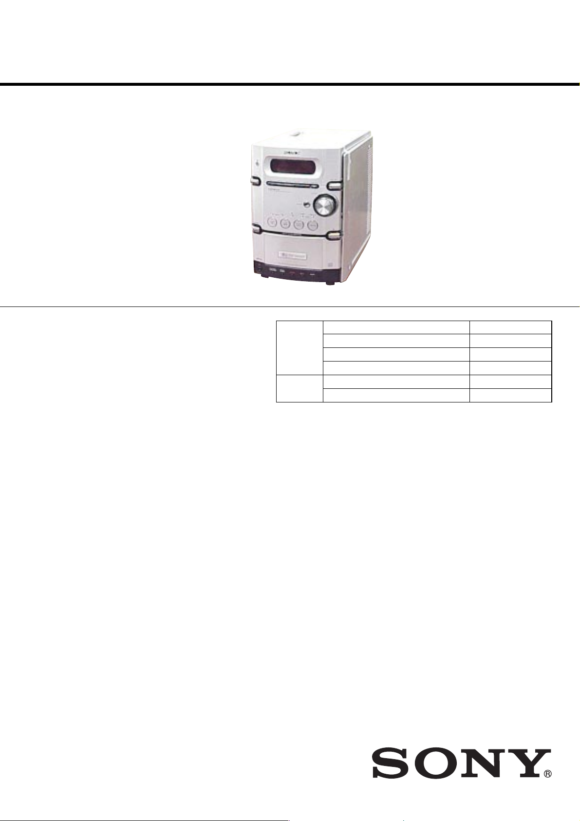
HCD-HPX7
SERVICE MANUAL
Ver. 1.3 2005.02
HCD-HPX7 is the amplifier, CD player,
tape deck and tuner section in CMT -HPX7.
CD CD Mechanism Type CDM82A-F1BD81
Section Base Unit Name BU-F1BD81A
Tape deck Model Name Using Similar Mechanism HCD-HPX9
Section Tape Transport Mechanism T ype CMAL5Z225A
Canadian Model
AEP Model
UK Model
E Model
Australian Model
Model Name Using Similar Mechanism HCD-HPX9
Optical Pick-up Block Name KSM-215DCP
Main unit
Amplifier section
European model:
DIN power output (rated): 50 + 50 W
Continuous RMS power output (reference):
Music power output (reference): 100 + 100 W
Other models:
The following measured at AC 240 V, AC 220 V or AC
120 V
DIN power output (rated): 45 + 45 W
Continuous RMS power output (reference):
Inputs
MD/VIDEO: Sensitivity 450/250 mV,
Outputs
PHONES: Accepts headphones with
SPEAKER: o Accepts impedance of 6 t
(6 ohms at 1 kHz, DIN)
60 + 60 W
(6 ohms at 1 kHz, 10%
THD)
(6 ohms at 1 kHz, DIN)
50 + 50 W
(6 ohms at 1 kHz, 10%
THD)
impedance 47 kilohms
an impedance of 8 ohms or
more.
16 ohms.
SPECIFICATIONS
CD player section
Laser Semiconductor laser
Frequency response 20 Hz – 20 kHz
Tape deck section
Recording system 4-track 2-channel, stereo
Frequency response 50 – 13,000 Hz (±3 dB),
Tuner section
FM stereo, FM/AM superheterodyne t uner
FM tuner section
Tuning range 87.5 – 108.0 MHz
Antenna FM lead antenna
Antenna terminals 75 ohms unbalanced
ntermediate frequency 10.7 MHz
I
AM tuner section
Tuning range
Pan-American model: 530 – 1,710 kHz
European model: 531 – 1,602 kHz
(λ=780 nm)
Emission duration:
continuous
using Sony TYPE I
cassettes
(with the tuning interval
set at 10 kHz)
531 – 1,710 kHz
(with the tuning interval
set at 9 kHz)
(with the tuning interval
set at 9 kHz)
Other models: 530 – 1,710 kHz
Antenna AM loop antenna, external
Intermediate frequency 450 kHz
General
Power requirements
North American model: 120 V AC, 60 Hz
Australian model: 230 – 240 V AC, 50/60 Hz
European model: 230 V AC, 50/60 Hz
Taiwan model:
Korean model:
Mexican model:
Other models: 120 V, 220 V or 230 – 240
Power consumption
European model: 115 W
Other models: 90 W
Design and specifications are subject to change
without notice.
(with the tuning interval
set at 10 kHz)
531 – 1,602 kHz
(with the tuning interval
set at 9 kHz)
antenna terminal
120 V AC, 50/600 Hz
220 V AC, 60 Hz
120 V AC, 60 Hz
V AC, 50/60 Hz
Adjustable with voltage
selector
9-877-911-04
2005B16-1
© 2005.02
COMPACT DISC DECK RECEIVER
Sony Corporation
Personal Audio Group
Published by Sony Engineering Corporation

HCD-HPX7
TABLE OF CONTENTS
1. SERVICING NOTES ................................................ 4
2. GENERAL ................................................................... 5
3. DISASSEMBLY
3-1. Disassembly Flow-1 ........................................................ 7
3-2. Disassembly Flow-2 ........................................................ 8
3-3. Optical Pick-Up Block .................................................... 9
3-4. Side Plate (L) (R), Top Panel Section.............................. 10
3-5. Mechanical Deck ............................................................. 11
3-6. Front Panel Section ......................................................... 12
3-7. PANEL (1), (2) Board, HEADPHONE Board ................ 12
3-8. Tuner (FM/AM), DC Fan ................................................ 13
3-9. MAIN Board.................................................................... 14
3-10. Rear Panel Section........................................................... 14
3-11. AMP Board, Switching Regulator................................... 15
3-12. POWER Board ................................................................ 15
3-13. CD Mechanism Deck (CDM82A)................................... 16
3-14. Plate (Cover Top) ............................................................. 17
3-15. Top Section...................................................................... 17
3-16. Arm Section..................................................................... 18
3-17. CD Mechanism Deck Section ......................................... 19
3-18. Sub Gear (2 Step), Sub Slider Assy................................. 20
3-19. Arm (R) ........................................................................... 21
3-20. Gear (Stock Planet) (Right) ............................................. 22
3-21. Lever (Sub Gear Back L) ................................................ 22
3-22. Arm (L)............................................................................ 23
3-23. Gear (Stock Rot Long) (Left) .......................................... 24
3-24. Gear (Stock Rot Short) (Right) ....................................... 24
3-25. Stocker (1) Assy To Stocker (5) Assy.............................. 25
3-26. SPR-E (Roller Slider Upper) (Top Section) .................... 26
3-27. Rubber Roller (Top Section) ........................................... 26
3-28. LOD Motor ...................................................................... 27
3-29. Slider (Push-popup)......................................................... 27
3-30. Rotary Encoder ................................................................ 28
3-31. Assembling of the Rotary Encoder ................................. 29
3-32. ELV Motor....................................................................... 30
3-33. Chassis (Top), Chassis (Bottom) ..................................... 31
3-34. Lever (Loading R, Loading L) ........................................ 32
3-35. Disc Stop Lever ............................................................... 33
3-36. DRIVER Board ............................................................... 33
3-37. CD Board......................................................................... 34
3-38. Optical Pick-up (KSM-215DCP) .................................... 34
3-39. Base Unit Section ............................................................ 35
3-40. Lever (BU Lock) ............................................................. 35
3-41. Gear (IDL-B) ................................................................... 36
3-42. Gear (IDL-C) ................................................................... 36
3-43. SPR-E (Tako-Back)......................................................... 37
3-44. Plate (Push) Assy............................................................. 38
3-45. SPR-P (Lock) .................................................................. 39
4. ASSEMBLY
4-1. Assembly Flow ................................................................ 40
4-2. Assembling of the Stocker Section ................................. 41
4-3. Assembling of the Gear (Stock Rot Short) (Right) ......... 42
4-4. Assembling of the Gear (Stock Rot Long) (Left)............ 43
4-5. Confirming the Assembling of the Stocker Section ........ 44
4-6. Assembling of the Gear (Stock Rotary Left)................... 45
4-7. Assembling of the Gear (Stock Rotary Right) ................ 46
4-8. Assembling of the Lever (Sub Gear Back L) .................. 47
4-9. Assembling of the Gear (Sub Gear Pin Right) ................ 48
4-10. Assembling of the Lever (Sub Gear Back R) .................. 49
4-11. Assembling of the Sub Gear (Idler) ................................ 50
4-12. Assembling of the Sub Gear (2 Step) .............................. 51
4-13. Confirming the Assembling of the Arm Section ............. 52
5. TEST MODE ............................................................... 53
6. ELECTRICAL ADJUSTMENTS .......................... 55
7. DIAGRAMS
7-1. Block Diagram – CD Servo Section –............................. 59
7-2. Block Diagram – MAIN Section – .................................. 60
7-3. Block Diagram
– PANEL/POWER SUPPLY Section – ........................... 61
7-4. Printed Wiring Board – CD Board – ............................... 62
7-5. Schematic Diagram – CD Board – .................................. 63
7-6. Printed Wiring Board – CD MECHANISM Section –.... 64
7-7. Schematic Diagram – CD MECHANISM Section – ...... 65
7-8. Printed Wiring Board – MAIN Board – .......................... 66
7-9. Schematic Diagram – MAIN Board (1/3) – .................... 67
7-10. Schematic Diagram – MAIN Board (2/3) – .................... 68
7-11. Schematic Diagram – MAIN Board (3/3) – .................... 69
7-12. Printed Wiring Board – AMP Board – ............................ 70
7-13. Schematic Diagram – AMP Board – ............................... 71
7-14. Printed Wiring Board – PANEL Section – ...................... 72
7-15. Schematic Diagram – PANEL Section –......................... 73
7-16. Printed Wiring Board – POWER Board – ....................... 74
7-17. Schematic Diagram – POWER Board –.......................... 75
8. EXPLODED VIEWS
8-1. Side Plate, Top Panel Section .......................................... 83
8-2. Front Panel Section ......................................................... 84
8-3. Chassis Section-1 ............................................................ 85
8-4. Chassis Section-2 ............................................................ 86
8-5. CD Mechanism Deck Section-1 (CDM82A) .................. 87
8-6. CD Mechanism Deck Section-2 (CDM82A) .................. 88
8-7. CD Mechanism Deck Section-3 (CDM82A) .................. 89
8-8. CD Mechanism Deck Section-4 (CDM82A) .................. 90
8-9. CD Mechanism Deck Section-5 (CDM82A) .................. 91
8-10. CD Mechanism Deck Section-6 (CDM82A) .................. 92
8-11. CD Mechanism Deck Section-7 (CDM82A) .................. 93
8-12. CD Mechanism Deck Section-8 (CDM82A) .................. 94
8-13. CD Mechanism Deck Section-9 (CDM82A) .................. 95
8-14. CD Mechanism Deck Section-10 (CDM82A) ................ 96
8-15. Base Unit Section (BU-F1BD81A) ................................. 97
9. ELECTRICAL PARTS LIST .................................. 98
2
HCD-HPX7
Notes on chip component replacement
• Never reuse a disconnected chip component.
• Notice that the minus side of a tantalum capacitor may be
damaged by heat.
Flexible Circuit Board Repairing
• Keep the temperature of the soldering iron around 270 °C
during repairing.
• Do not touch the soldering iron on the same conductor of the
circuit board (within 3 times).
• Be careful not to apply force on the conductor when soldering
or unsoldering.
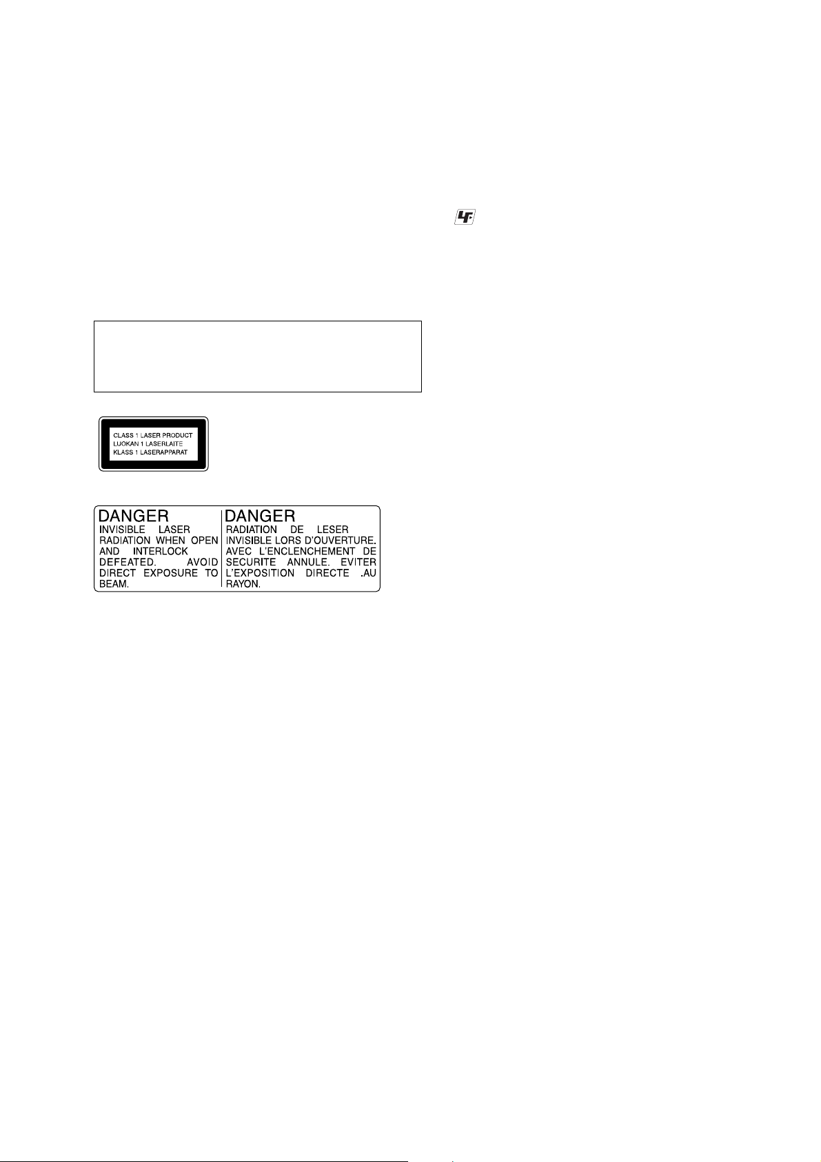
CAUTION
Use of controls or adjustments or performance of procedures
other than those specified herein may result in hazardous radiation
exposure.
This appliance is
classified as a CLASS 1
LASER product. This
label is located on the
rear exterior.
UNLEADED SOLDER
Boards requiring use of unleaded solder are printed with the leadfree mark (LF) indicating the solder contains no lead.
(Caution: Some printed circuit boards may not come printed with
the lead free mark due to their particular size)
: LEAD FREE MARK
Unleaded solder has the following characteristics.
• Unleaded solder melts at a temperature about 40 °C higher
than ordinary solder.
Ordinary soldering irons can be used but the iron tip has to be
applied to the solder joint for a slightly longer time.
Soldering irons using a temperature regulator should be set to
about 350 °C.
Caution: The printed pattern (copper foil) may peel away if
the heated tip is applied for too long, so be careful!
• Strong viscosity
Unleaded solder is more viscou-s (sticky, less prone to flow)
than ordinary solder so use caution not to let solder bridges
occur such as on IC pins, etc.
• Usable with ordinary solder
It is best to use only unleaded solder but unleaded solder may
also be added to ordinary solder.
SAFETY-RELATED COMPONENT WARNING!!
COMPONENTS IDENTIFIED BY MARK 0 OR DOTTED LINE
WITH MARK 0 ON THE SCHEMATIC DIAGRAMS AND IN
THE PARTS LIST ARE CRITICAL TO SAFE OPERATION.
REPLACE THESE COMPONENTS WITH SONY PARTS WHOSE
PART NUMBERS APPEAR AS SHOWN IN THIS MANUAL OR
IN SUPPLEMENTS PUBLISHED BY SONY.
ATTENTION AU COMPOSANT AYANT RAPPORT
À LA SÉCURITÉ!
LES COMPOSANTS IDENTIFIÉS PAR UNE MARQUE 0 SUR
LES DIAGRAMMES SCHÉMATIQUES ET LA LISTE DES
PIÈCES SONT CRITIQUES POUR LA SÉCURITÉ DE
FONCTIONNEMENT. NE REMPLACER CES COM- POSANTS
QUE PAR DES PIÈCES SONY DONT LES NUMÉROS SONT
DONNÉS DANS CE MANUEL OU DANS LES SUPPLÉMENTS
PUBLIÉS PAR SONY.
3
HCD-HPX7
SECTION 1
SERVICING NOTES
NOTES ON HANDLING THE OPTICAL PICK-UP
BLOCK OR BASE UNIT
The laser diode in the optical pick-up block may suffer electrostatic
break-down because of the potential difference generated by the
charged electrostatic load, etc. on clothing and the human body.
During repair, pay attention to electrostatic break-down and also
use the procedure in the printed matter which is included in the
repair parts.
The flexible board is easily damaged and should be handled with
care.
NOTES ON LASER DIODE EMISSION CHECK
The laser beam on this model is concentrated so as to be focused on
the disc reflective surface by the objective lens in the optical pickup block. Therefore, when checking the laser diode emission,
observe from more than 30 cm away from the objective lens.
LASER DIODE AND FOCUS SEARCH OPERATION
CHECK
Carry out the “S curve check” in “CD section adjustment” and check
that the S curve waveforms is output three times.
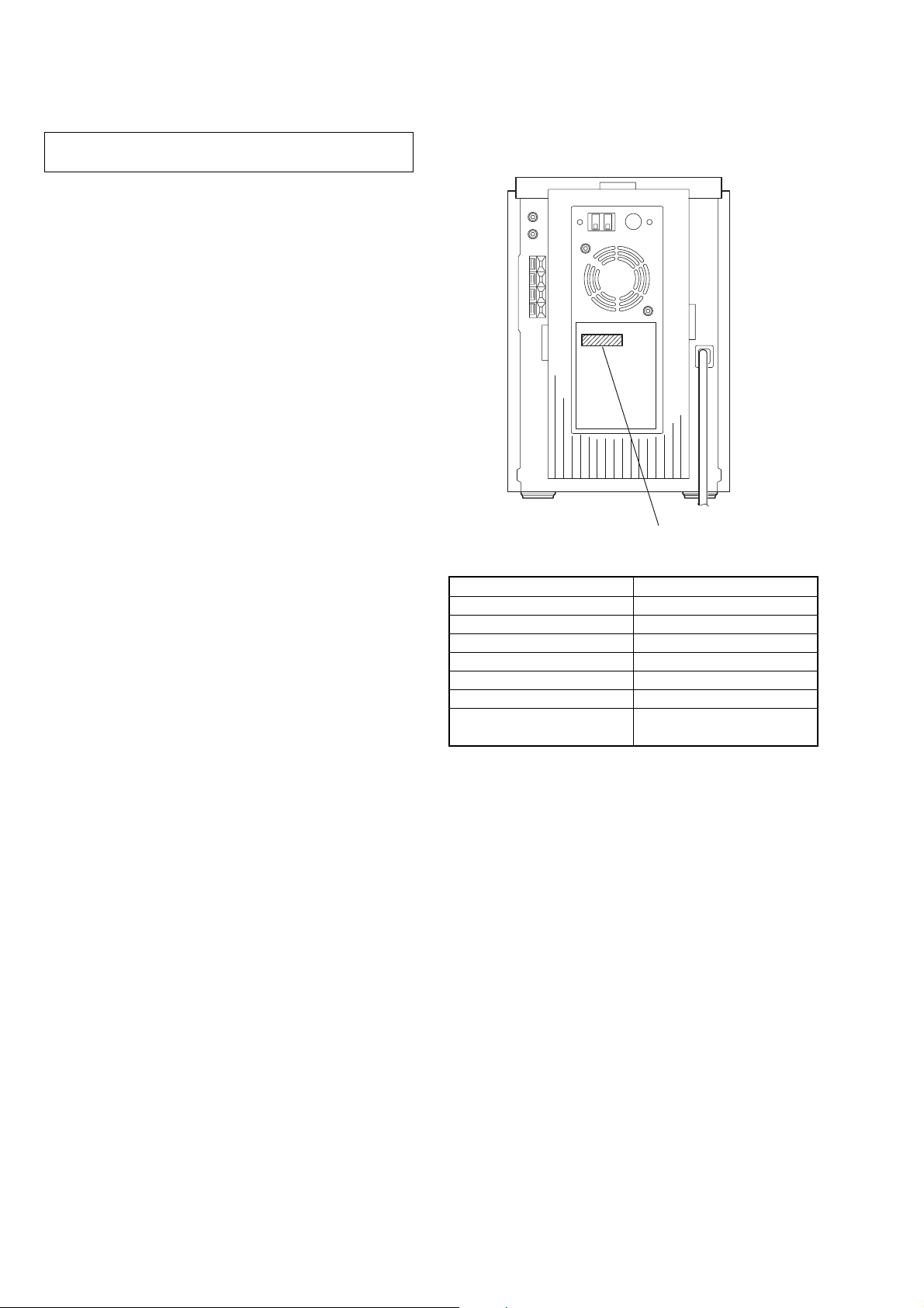
• MODEL IDENTIFICATION
– Rear View –
Power requirement
indication
Model Name Power Voltage Indication
Canadian model AC: 120 V - 60 Hz
Australian model AC: 230 – 240 V - 50/60 Hz
AEP, UK models AC: 230 V - 50/60 Hz
Taiwan model AC: 120 V - 50/60 Hz
Korean model AC: 220 V - 60 Hz
Mexican model AC: 120 V - 60 Hz
Other models
AC: 120 V, 220 V, 230 – 240 V
- 50/60 Hz
4
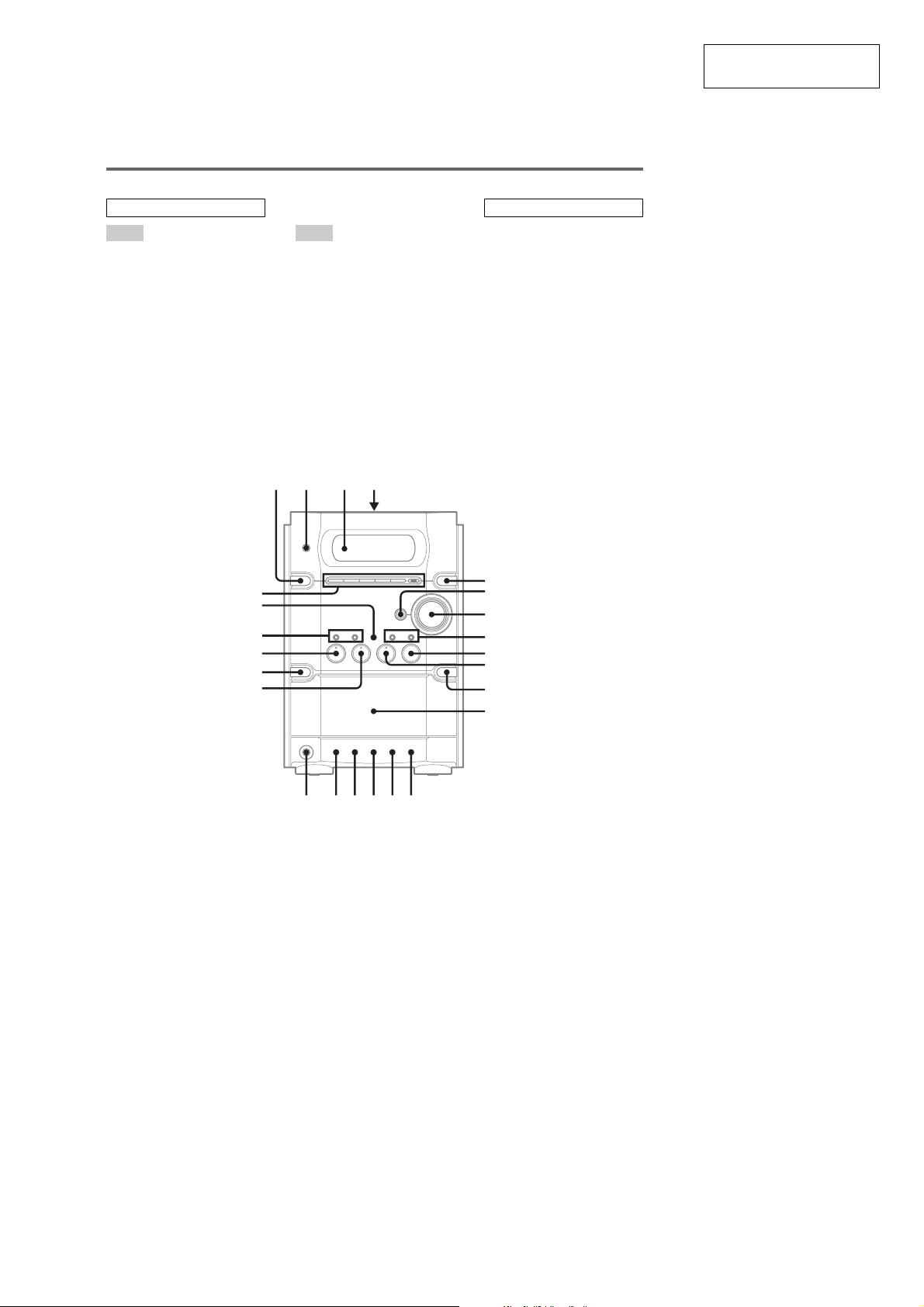
• LOCATION OF CONTROLS
Main unit
ALPHABETICAL ORDER
A – O P – Z
ALBUM +/– ws (11, 13)
Cassette compartment 4
CD SYNC qg (18)
DISC 1 – 5, +1 wf (11, 13)
DISC SKIP 5 (11, 13)
Disc tray qs (10)
Display window 3
DSGX 6 (19)
EX-CHANGE w; (10)
FM MODE qh (16, 27)
FUNCTION 9 (11, 13, 15, 17,
23)
PHONES jack qk
PLAY MODE qj (11, 13, 18)
Remote sensor 2
REPEAT qh (12)
TUNER/BAND 0 (14, 15)
TUNING +/– 8 (14, 15)
TUNING MODE qj (14, 15)
VOLUME 7 (20, 26)
12 34
SECTION 2
GENERAL
BUTTON DESCRIPTIONS
?/1 (power) 1 (8, 15, 20, 21,
28)
.m/M> (skip back/
skip forward, rewind/fast
forward) 8 (11, 13)
x wd (11, 15, 28)
X TAPE (pause) qd (17)
z REC qf (18)
CD/NX (play/pause) ql (11,
13, 27)
TAPE/N (play) wa (17)
Z (CD eject) qa (10, 11)
HCD-HPX7
This section is extracted
from instruction manual.
wf
wd
ws
wa
w;
ql
+/1
5
6
7
x
lj JL
HS
8
9
A
0
qa
qs
zX
qf
qdqhqjqk qg
5
HCD-HPX7
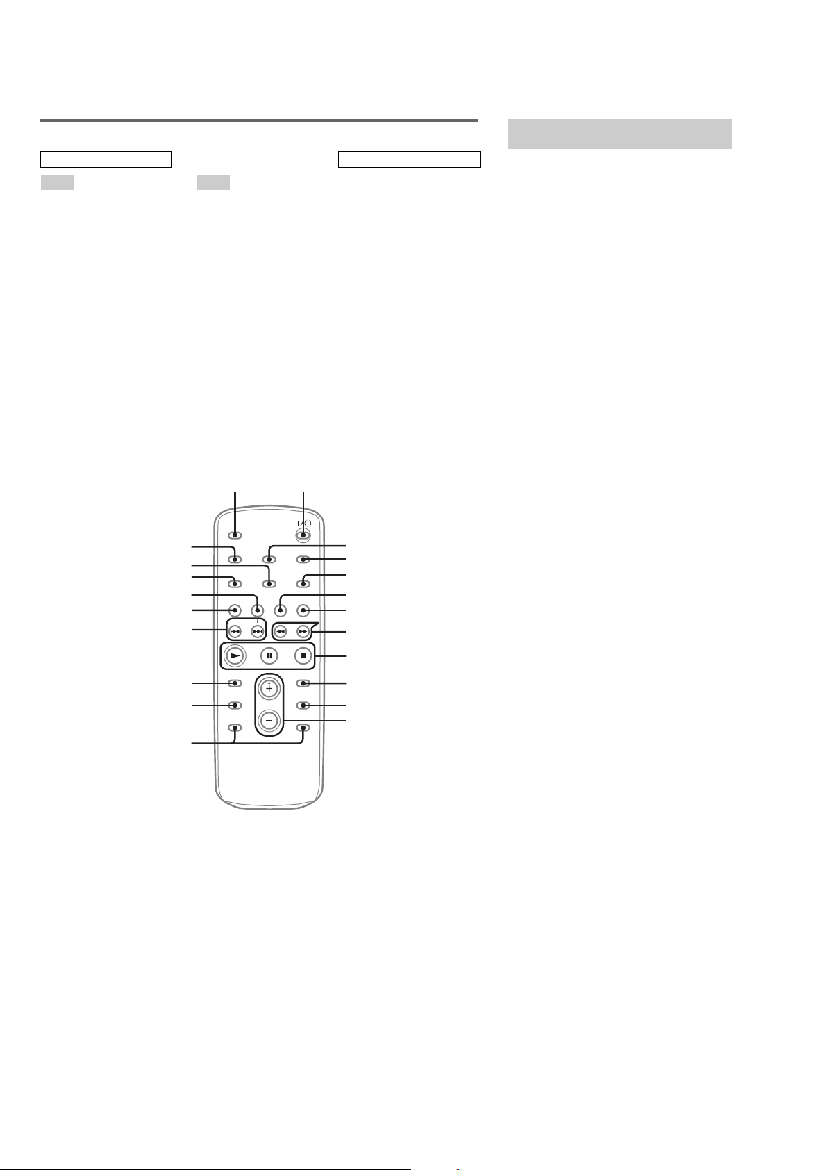
Remote control
ALPHABETICAL ORDER
A – O
ALBUM +/– qs (11, 13)
CD qj (11, 13, 15)
CLEAR qf (13)
CLOCK/TIMER SELECT 2
(20, 21, 26)
CLOCK/TIMER SET 3 (9, 20,
21)
DISC SKIP 0 (11, 13)
DISPLAY w; (16, 22)
ENTER 9 (9, 13, 20, 21)
EQ qd (19)
FM MODE 4 (16, 27)
FUNCTION 6 (11, 13, 15, 17,
23)
P – Z
PLAY MODE ql (11, 13, 18)
REPEAT 4 (12)
SLEEP wa (19)
TAPE qh (17)
TUNER/BAND 5 (14, 15)
TUNER MEMORY qk (14)
TUNING MODE ql (14, 15)
VOLUME +/– qa (20, 26)
wa 1
BUTTON DESCRIPTIONS
?/1 (power) 1 (8, 15, 20, 21,
28)
m/M (rewind/fast forward)
7 (11, 17)
./> (skip back/skip
forward) qg (9, 11, 13, 19, 20,
21)
x (stop) 8 (11, 15, 17, 18, 28)
X (pause) 8 (11, 17)
N (play) 8 (11, 13, 17, 27)
+/– (tuning) qg (14, 15)
Setting the clock
Use buttons on the remote for the operation.
1
Press ?/1 to turn on the system.
2
Press CLOCK/TIMER SET.
3
Press ./> repeatedly to set the
hour.
4
Press ENTER.
5
Press ./> repeatedly to set the
minute.
6
Press ENTER.
The clock starts working.
To adjust the clock
1
Press CLOCK/TIMER SET.
2
Press ./> until “CLOCK SET”
appears, then press ENTER.
3
Do the same procedures as step 3 to 6
above.
Note
The clock is not displayed in Power Saving Mode
w;
ql
qk
qj
qh
qg
qf
qd
qs
2
3
4
5
6
7
8
9
0
qa
6
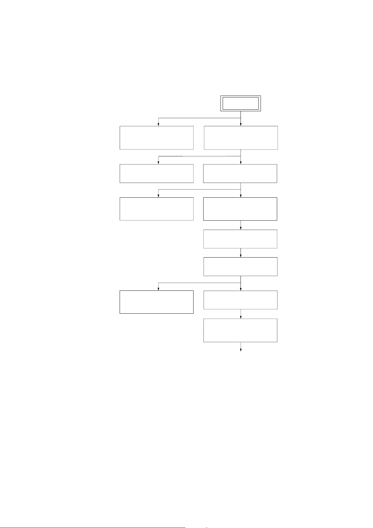
SECTION 3
DISASSEMBLY
•This is can be disassemble according to the following sequence.
3-1. DISASSEMBLY FLOW-1
HCD-HPX7
SET
3-3.OPTICAL PICK-UP
BLOCK
(Page 9)
3-5.MECHANICAL DECK
(Page 11)
3-7.PANEL (1), (2) BOARD
HEADPHONE BOARD
(Page 12)
3-11.AMP BOARD,
SWITCHING REGULATOR
(Page 15)
3-4.SIDE PLATE (L) (R),
TOP PANEL SECTION
(Page 10)
3-6.FRONT PANEL SECTION
(Page 12)
3-8.TUNER (FM/AM),
DC FAN
(Page 13)
3-9.MAIN BOARD
(Page 14)
3-10.REAR PANEL SECTION
(Page 14)
3-12.POWER BOARD
(Page 15)
3-13.CD MECHANISM DECK
(CDM82A)
(Page 16)
to DISASSEMBLY FLOW-2
7
HCD-HPX7
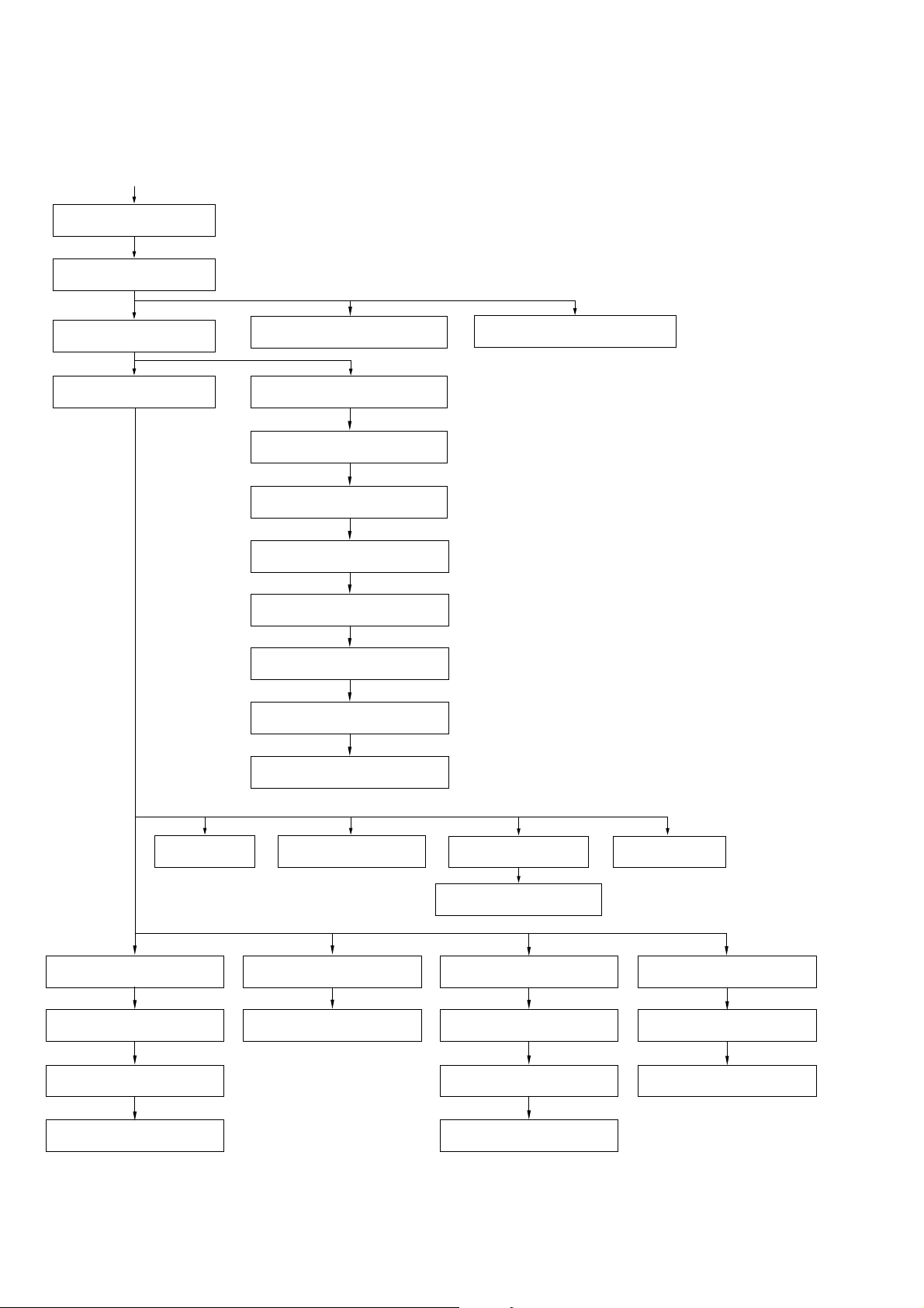
3-2. DISASSEMBLY FLOW-2
from DISASSEMBLY FLOW-1
3-14. PLATE (COVER TOP)
(Page 17)
3-15. T OP SECTION
(Page 17)
3-16. ARM SECTION
(Page 18)
3-17. CD MECHANISM DECK
SECTION (Page 19)
3-26. SPR-E (ROLLER SLIDER UPPER)
(TOP SECTION) (Page 26)
3-18. SUB GEAR (2 STEP),
SUB SLIDER ASSY (Page 20)
3-19. ARM (R)
(Page 21)
3-20. GEAR (STOCK PLANET)
(RIGHT) (Page 22)
3-21. LEVER (SUB GEAR BACK L)
(Page 22)
3-22. ARM (L)
(Page 23)
3-23. GEAR (STOCK ROT LONG)
(LEFT) (Page 24)
3-24. GEAR (STOCK ROT SHORT)
(RIGHT) (Page 24)
3-25. STOCKER (1) ASSY TO
STOCKER (5) ASSY (Page 25)
3-27. RUBBER ROLLER
(TOP SECTION) (Page 26)
3-28. LOD MOTOR
(Page 27)
3-33. CHASSIS (TOP),
CHASSIS (BOTTOM) (Page 31)
3-34. LEVER
(LOADING R, LOADING L) (Page 32)
3-35. DISC STOP LEVER
(Page 33)
3-36. DRIVER BOARD
(Page 33)
8
3-29. SLIDER (PUSH-POPUP)
(Page 27)
3-37. CD BOARD
(Page 34)
3-38. OPTICAL PICK-UP
(KSM-215DCP) (Page 34)
3-30. ROTARY ENCODER
(Page 28)
3-31. ASSEMBLING OF THE
ROTARY ENCODER (Page 29)
3-39. BASE UNIT SECTION
(Page 35)
3-40. LEVER (BU LOCK)
(Page 35)
3-41. GEAR (IDL-B)
(Page 36)
3-42. GEAR (IDL-C)
(Page 36)
3-32. ELV MOTOR
(Page 30)
3-43. SPR-E (TAKO-BACK)
(Page 37)
3-44. PLATE (PUSH) ASSY
(Page 38)
3-45. SPR-P (LOCK)
(Page 39)
k
Note: Follow the disassembly procedure in the numerical order given.
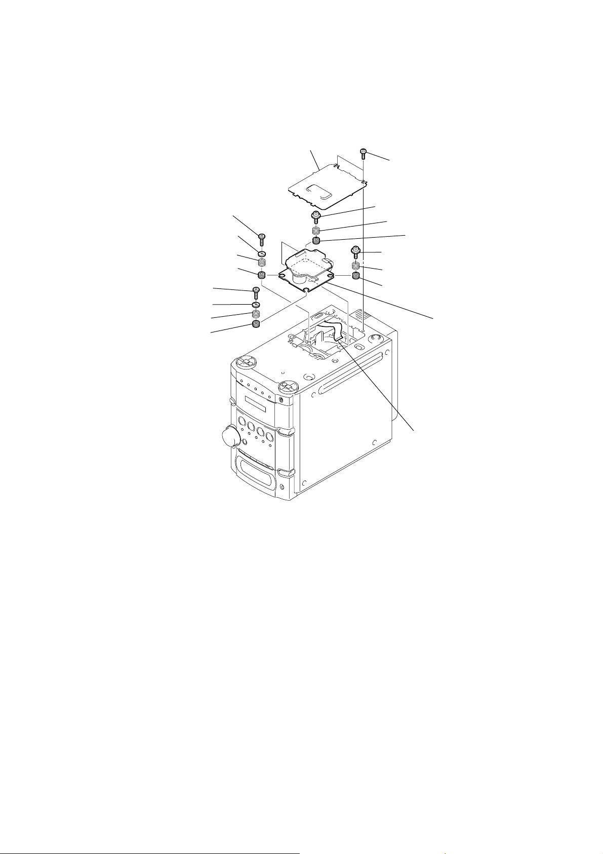
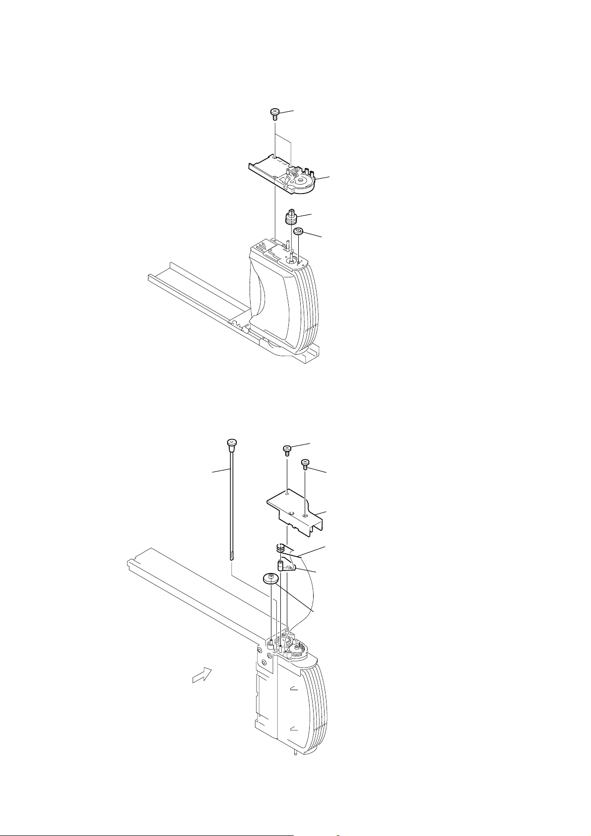
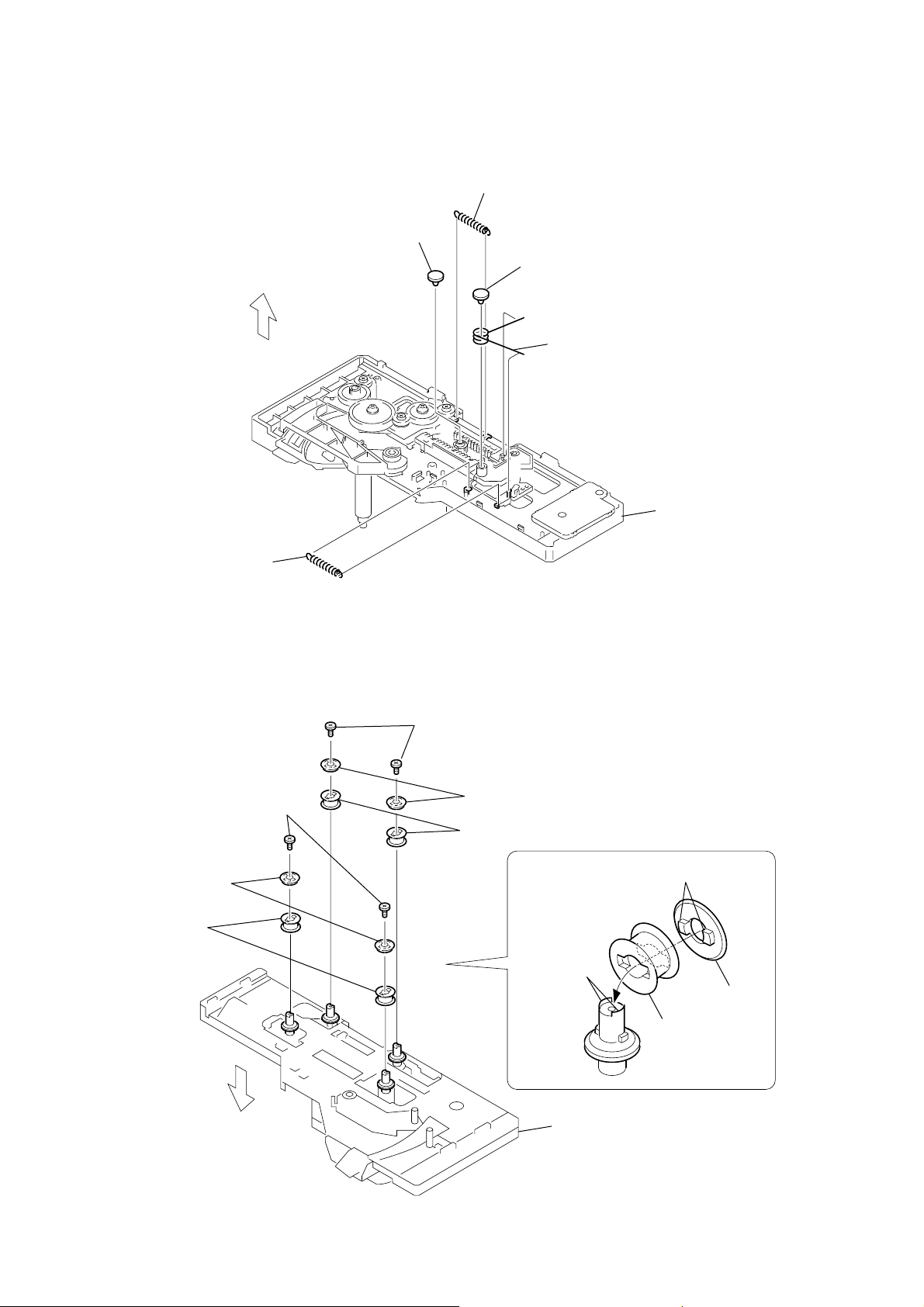
3-3. OPTICAL PICK-UP BLOCK
2
bottom cover plate
4
screw
(BTTP M2.6)
5
BU stopper
6
insulator spring (coil)
qf
insulator
7
screw
(BTTP M2.6)
8
BU stopper
9
insulator spring (coil)
qg
insulator
1
two screws
(BVTT3
0
flotaing screw
(+PTPWH M2.6)
qa
insulator spring (coil)
qh
qs
flotaing screw
(+PTPWH M2.6)
qd
insulator spring (coil)
qj
insulator
×
6
)
insulator
qk
optical pick-up bloc
HCD-HPX7
3
w
27p(CN201)
ire (flat type)
9
HCD-HPX7
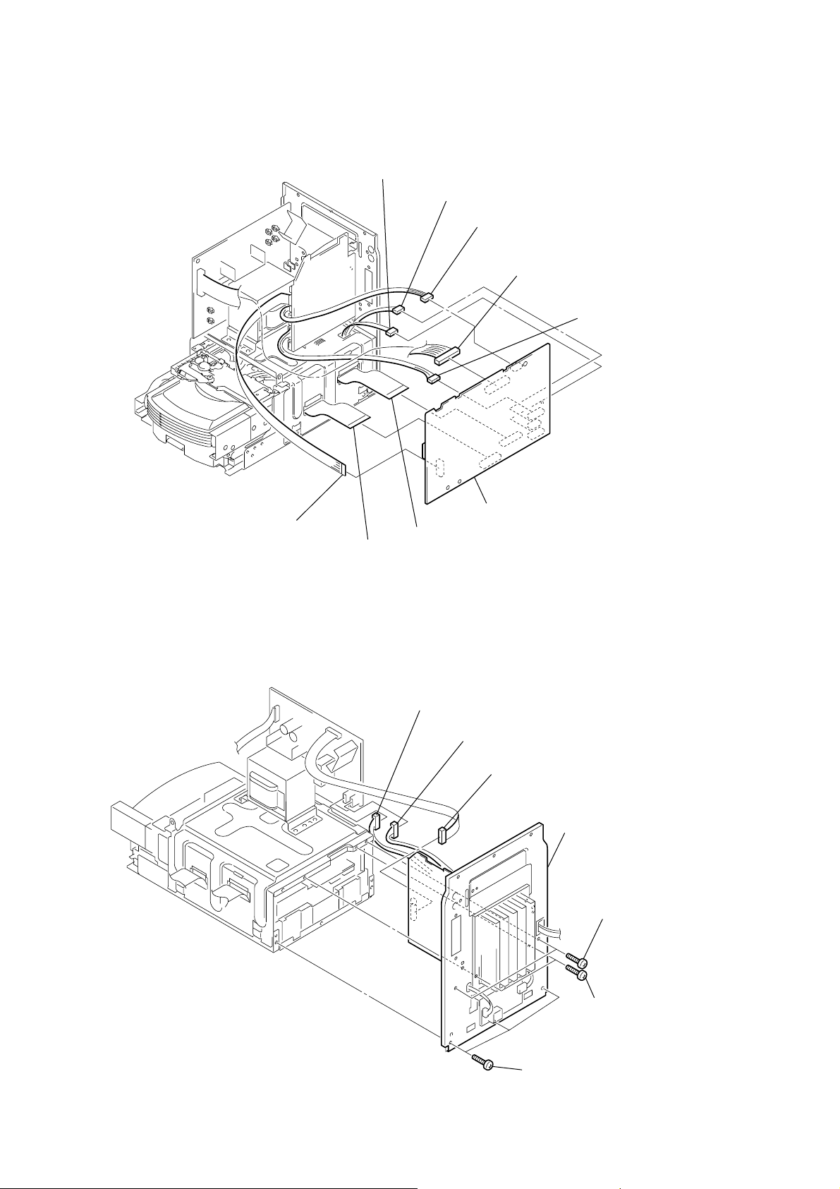
)
3-4. SIDE PLATE (L) (R), TOP PANEL SECTION
qs
top panel section
5
6
two screws
(BVTP3
two screws
(BVTP3
×
×
6
)
10
7
side plate (L)
)
qa
screw
(BVTP3
×
6
)
8
two screws
(BVTP3
9
w
ire (flat type)
7p(CN317)
×
8
)
0
connector
(CN301)
4
side plate (R) assy
3
shield cover
When you exchange Side plate (R) assy,
please remove Shield cover from old Side plate (R),
and attach in new Side plate (R).
2
two screws
(BVTT3
1
two screws
(BVTP3
×
×
10
6
)
10
3-5. MECHANICAL DECK
)
7
cassette shield plate
0
leaf spring (cassette)
2
three screws
(BVTP2.6
×
8
)
6
two screws
(BVTP2.6
HCD-HPX7
×
8
)
5
two screws
(BVTP2.6
×
8
)
earth wire
8
mechanical deck
qa
cassette panel
1
three screws
(BVTP2.6
9
leaf spring (cassette
×
8
)
4
cassette door
3
top panel
11
HCD-HPX7
3-6. FRONT PANEL SECTION
7
front panel section
2
screw
(KTP3
×
8
)
5
w
ire (flat type) 19p(CN310)
3
CD panel
4
two screws
(BVTT3
3-7. PANEL (1), (2) BOARD, HEADPHONE BOARD
4
five screws
(BVTP2.6
1
screw
×
6
)
6
17p(CN801)
×
8
)
(KTP3
×
8
w
ire (flat type)
qa
(CN312)
0
connector
(CN311)
6
connector
(CN604)
)
connector
5
seven screws
(BVTP2.6
8
×
8
)
PANEL (1) board
9
screw
(PWH2.6
qs
HEADPHONE board
qf
PANEL (2) board
qd
four screws
(BVTP2.6
×
10
)
×
8
)
1
12
knob
(volume)
2
nut
3
washer
7
connector
(CN802)
qg
claw
3-8. TUNER (FM/AM), DC FAN
)
HCD-HPX7
1
two screws
(BVTP3
MAIN board
×
8
)
2
screw
(BVTP3
×
8
)
9
w
ire (flat type) 11p or 15p(CN305)
8
5
claw
3
two screws
(BVTP3
connector
×
8
)
(CN313)
7
4
three screws
(BVTP3
heat sink cover
6
claw
×
8
)
qs
w
ire (flat type) 11p or 15p
qd
heat cover plate
qa
tuner (FM/AM)
qg
DC fan
qf
heat sink cover
0
two screws
(BVTP3
two screws (FAN)
×
10
13
HCD-HPX7
)
3-9. MAIN BOARD
6
connector
(CN308)
5
connector
(CN303)
3
connector
(CN316)
2
connector
(CN307)
4
connector
(CN309)
3-10. REAR PANEL SECTION
1
w
ire (flat type)
(9p)(CN306)
7
w
ire (flat type)
(21p)(CN315)
4
(CN904)
8
w
ire (flat type)
(27p)(CN304)
connector
5
connector
(CN903)
9
MAIN board
6
connector
(CN602)
7
rear panel section
1
two screws
(BVTP3
×
8)
14
3
three screws
(BVTP3
2
two screws
(BVTP3
×
8
)
×
16
3-11. AMP BOARD, SWITCHING REGULATOR
7
screw
(BVTP3
8
two screws
(BVTP3
9
AMP board
×
16
)
HCD-HPX7
rear panel
×
8
)
5
two screws
(BVTP3
×
12
)
6
main heat sink
1
connector
(CN101)
3-12. POWER BOARD
3
two screws
(BVTT4
5
POWER board
×
6
)
1
connector
(CN901)
2
connector
(CN201)
2
connector
(CN902)
3
two screws
(BVTP3
4
SWITCHING REGULATOR
×
6
)
4
two screws
(BVTT4
×
6
)
15
HCD-HPX7
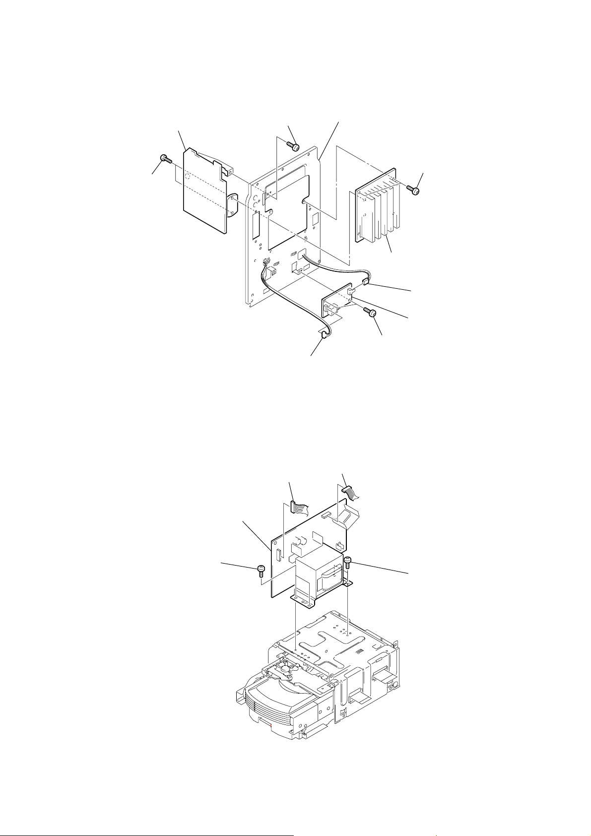
3-13. CD MECHANISM DECK (CDM82A)
1
two screws
(BVTT3
×
6
)
3
sub chassis
2
two screws
(BVTT3
×
6
8
plate
6
)
screw
(BVTP2.6
7
screw
(BVTT3
4
5
clamp
×
8
)
×
6
screw
(BVTP2.6
Please attach connector,
as shown in a figure.
plate
)
×
8
)
sub chassis
connector
clamp
qd
w
21p (CN202)
qa
w
ire (flat type)
27p (CN801)
ire (flat type)
9
four screws
(BVTT3
0
chassis
qs
×
10
)
ffc cover
qf
CD mechanism deck
(CDM82A)
16
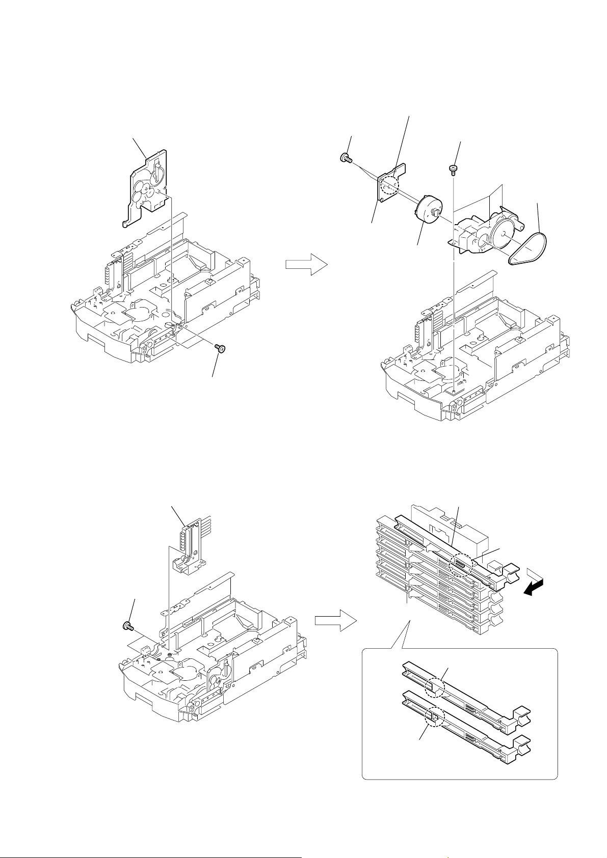
3-14. PLATE (COVER TOP)
)
2
gear (joint op), shaft (stock)
7
screw
(BTTPM 2.6
3
four screws
(BTTPM 2.6
8
plate (cam R)
×
8)
×
HCD-HPX7
8)
4
plate (cover top)
3-15. TOP SECTION
3
two screws
×
(BTP 2
8)
shock guard
(lower)
1
screw (BTP 2
2
gear (connection tp)
×
8)
4
two screws
(PTPWH 2
7
top section
×
14)
1
gear (joint op)
6
plate (cam L)
5
screw
(BTTPM 2.6
6
shock guard
(lower)
5
claw
×
8
8
shaft (connection)
17
HCD-HPX7
3-16. ARM SECTION
2
Slide the arm section in the
direction of the arrow B.
5
Remove the
in the direction of the arrow D.
arm section
3
claw
B
1
T
urn over the
in the direction of the arrow
PRECAUTION DURING ARM SECTION
INSTALLATION
pulley (LOD motor)
A
.
1
gear (joint op),
two shaft (shaft) stocks
A
D
6
arm section
C
4
Push this portion with a finger
in the direction of the arrow C.
3
turn over the
gear (swing)
in the direction
of the arrow.
6
Push this portion with a finger
in the direction of the arrow C.
gear (swing)
5
arm section
2
loosen two
screws
4
two claws
8
gear (joint op), two shaft (shaft) stocks
7
two
screws
18
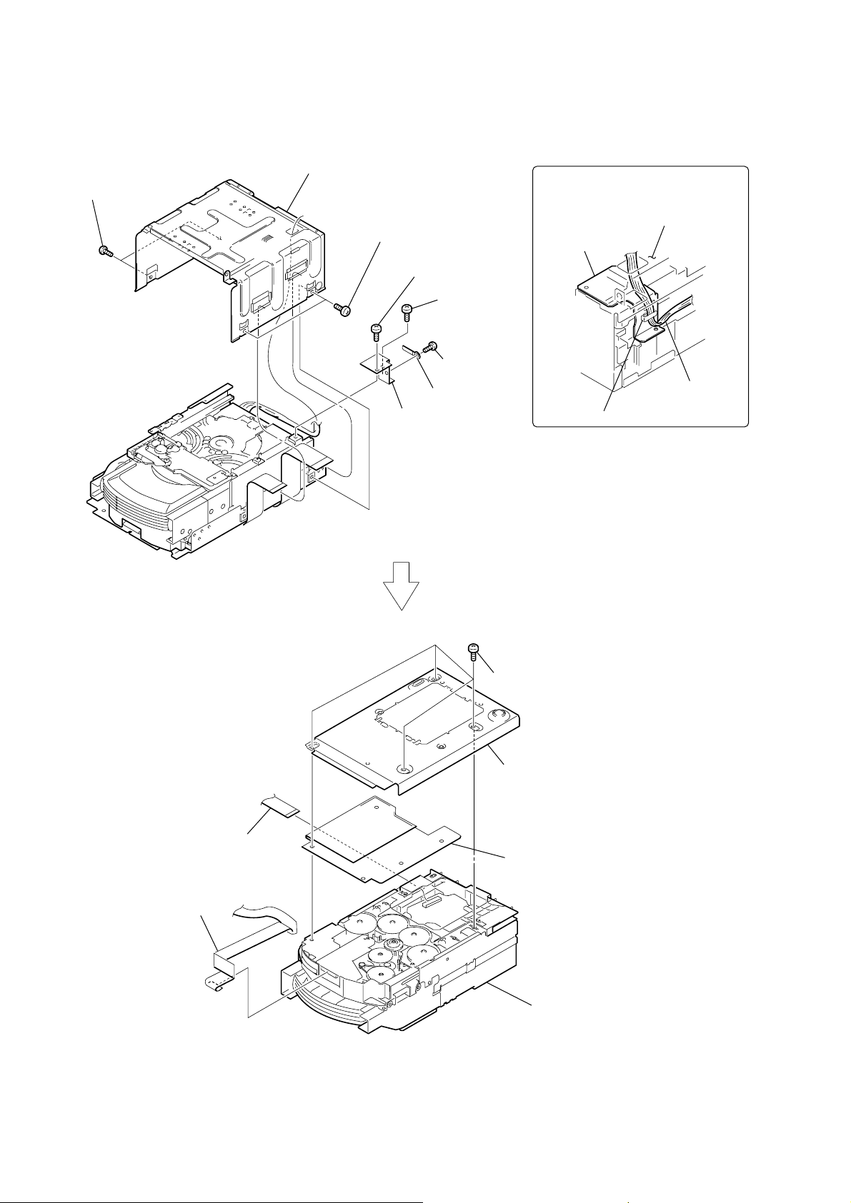
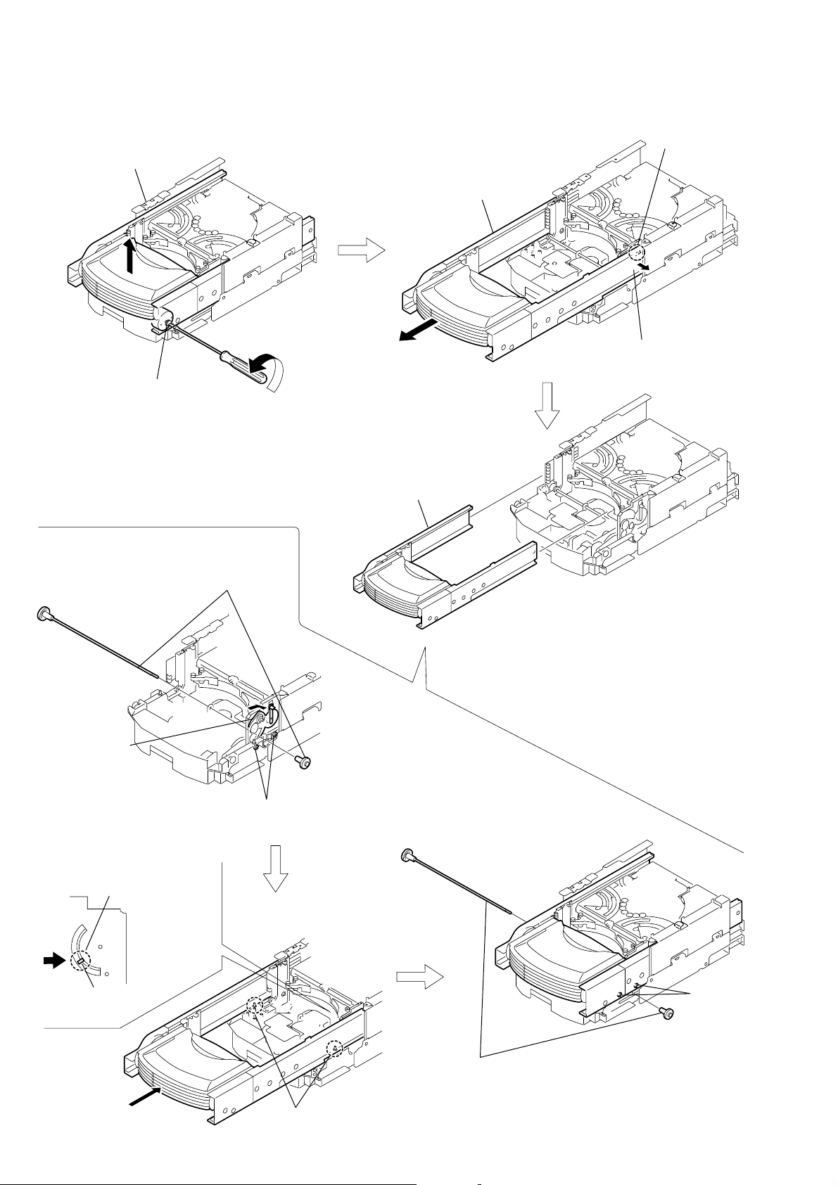
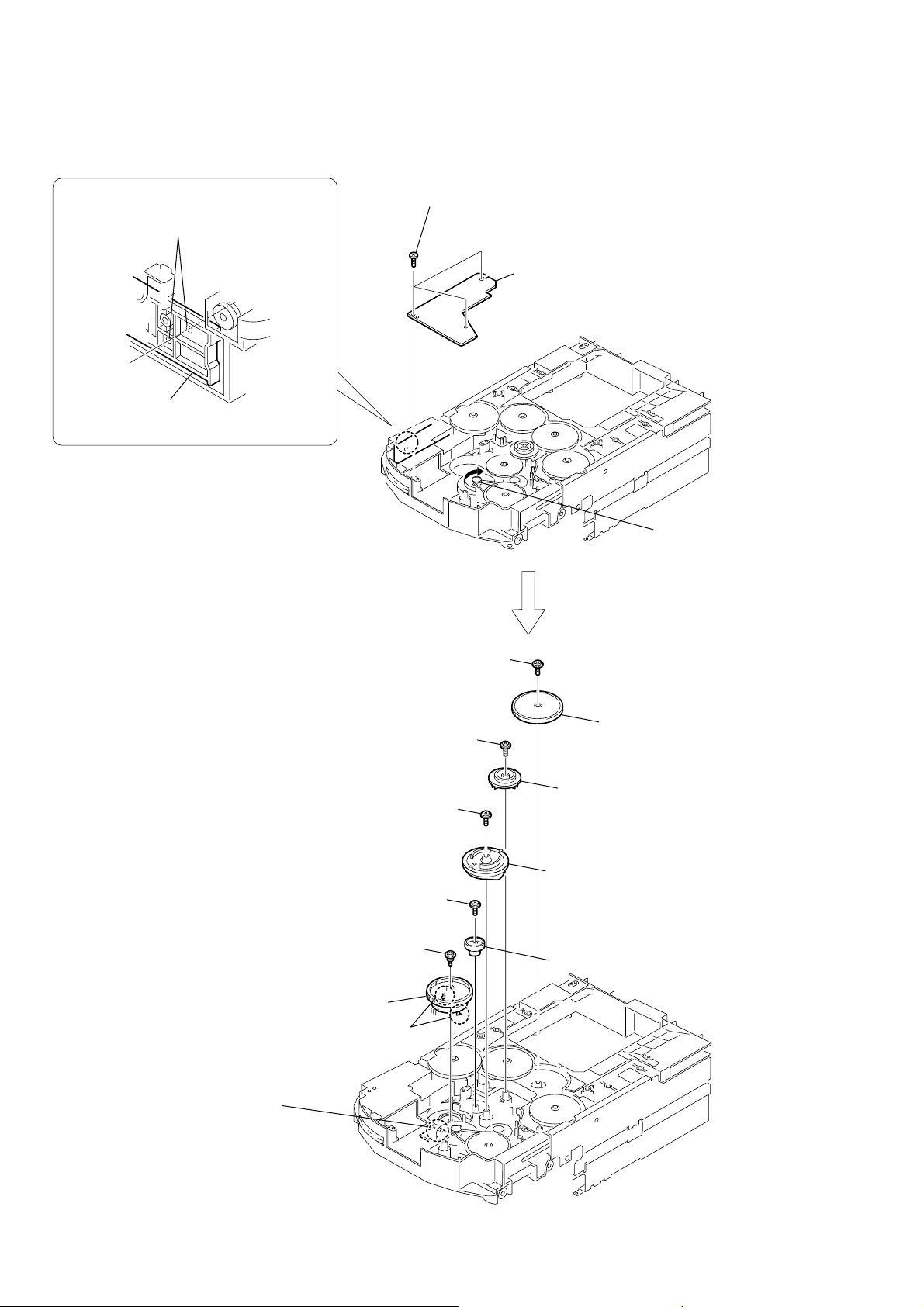
3-17. CD MECHANISM DECK SECTION
pulley (ELV motor)
A
2
Slide the
in the direction of the arrow
B
CD mechanism deck section
HCD-HPX7
B
.
1
T
urn over the
in the direction of the arrow
pulley (ELV motor)
plate (cam L)
A
.
3
four
claws
4
Remove the CD mechanism deck section
in the direction of the arrow
C
C
.
19
HCD-HPX7
3-18. SUB GEAR (2 STEP), SUB SLIDER ASSY
9
Remove the
in the direction of the arrow.
sub slider assy
0
sub slider assy
5
sub gear (2 step)
sub slider assy
4
sub gear (idler)
1
k tapping screw (K2.6
3
2
two screws (M2
×
8)
cover (R)
×
5)
20
6
7
sub gear (idler)
8
sub gear (idler)
sub gear (idler)
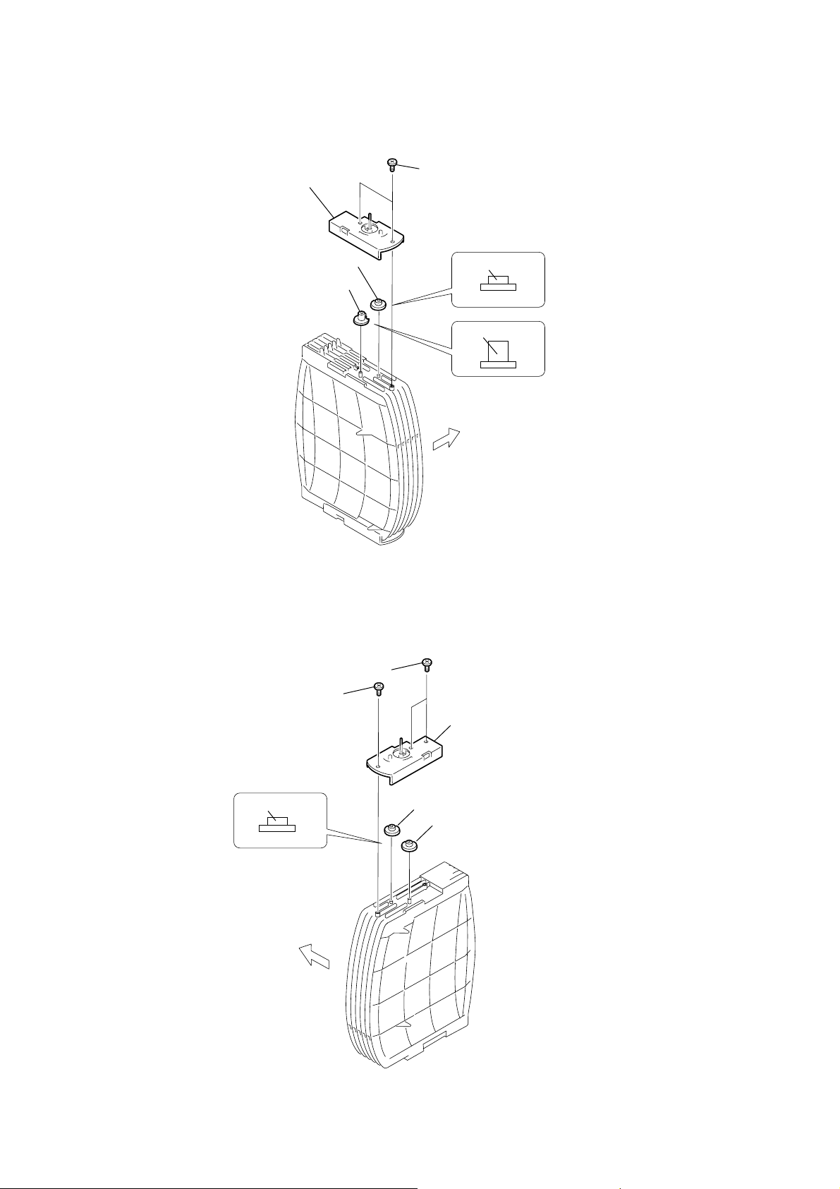
3-19. ARM (R)
)
3
lever (sub gear back R)
1
sub gear (joint just front)
2
SPR-T (sub gear back R)
HCD-HPX7
7
gear (stock joint)
6
gear (stock rotary right)
5
gear (sub gear pin right
4
two washers (5.5)
9
arm (R)
8
two screws
× 5
(K2
)
21
HCD-HPX7
)
)
3-20. GEAR (STOCK PLANET) (RIGHT)
1
two screws (BTTP M2.6
2
stock base (A)
3
gear (stock sun)
4
gear (stock planet)
×
6
3-21. LEVER (SUB GEAR BACK L)
5
gear (stock joint),
shaft (stock)
UPPER
SIDE
2
screw (M2
1
3
6
7
lever (sub gear back L)
4
sub gear (joint just front)
×
5)
screw (K2.6
cover (L)
SPR-T (sub gear back L
×
8)
22
3-22. ARM (L)
)
4
arm (L), stock base (B)
1
two washers (5.5)
UPPER
SIDE
HCD-HPX7
2
gear (sub gear pin right
3
gear (stock rotary right)
6
gear (stock sun)
5
gear (stock planet)
UPPER
SIDE
23
HCD-HPX7
)
3-23. GEAR (STOCK ROT LONG) (LEFT)
2
stock box (L)
3
gear (stock rot short)
4
gear (stock rot long)
1
two screws (2
short
long
UPPER
SIDE
×
6)
3-24. GEAR (STOCK ROT SHORT) (RIGHT)
1
two screws (2
2
screw (1.7)
short
UPPER
SIDE
×
6)
3
stock box (R)
4
gear (stock rot short)
5
gear (stock rot short
24
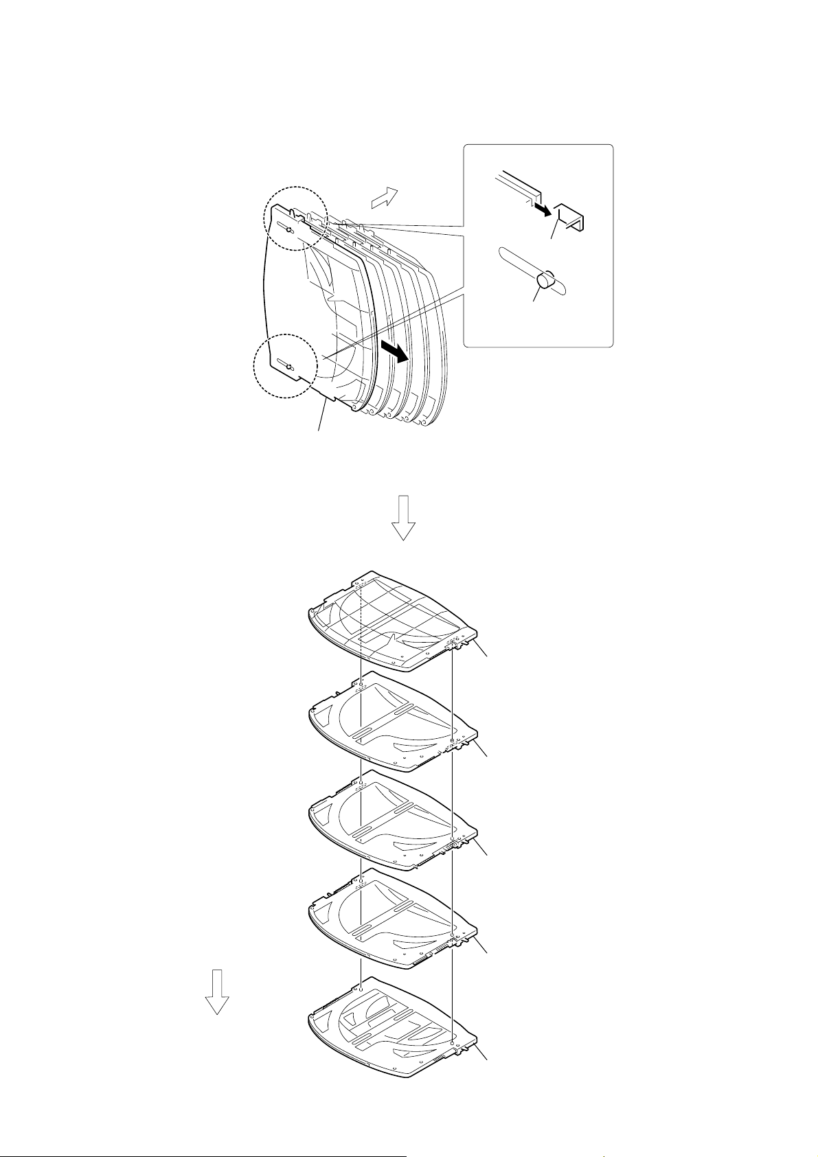
3-25. STOCKER (1) ASSY TO STOCKER (5) ASSY
UPPER
SIDE
1
dowel
2
claw
HCD-HPX7
3
Remove the stocker
in the direction of the arrow.
(1) assy
Repeat the steps 1 to 1, when removing the part
(2), (3), (4) and (5) of the stocker assy.
4
stocker (1) assy
5
stocker (2) assy
UPPER
SIDE
6
stocker (3) assy
7
stocker (4) assy
8
stocker (5) assy
25
HCD-HPX7
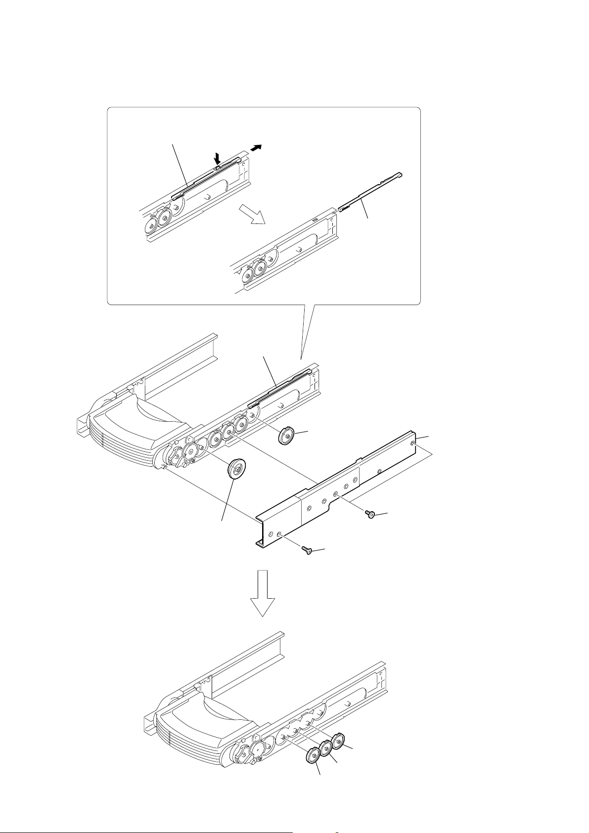
3-26. SPR-E (ROLLER SLIDER UPPER) (TOP SECTION)
5
bushing
UPPER
SIDE
3
SPR-E (8 cm slider L)
1
bushing
2
SPR-T (8 cm slider R)
4
SPR-E
(roller slider upper)
3-27. RUBBER ROLLER (TOP SECTION)
4
two screws
×
5)
(2
5
two parasols
6
two
rubber rollers
1
two screws
×
5)
(2
2
two parasols
3
two
rubber rollers
top section
two claws
26
UPPER
SIDE
two claws
parasol
rubber roller
top section
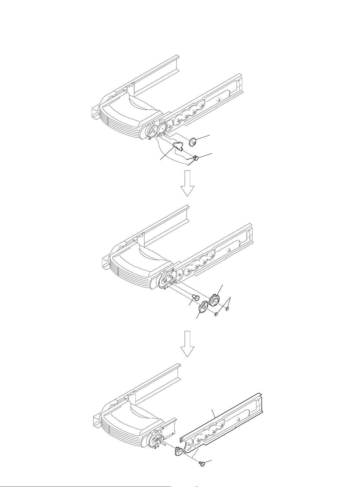
3-28. LOD MOTOR
)
3
claw
4
Remove the slider (push-popup1)
in the direction of the arrow.
2
sub chassis assy (R)
slider (push-popup 1)
slider (push-popup 2)
1
two screws
(BTTP M2.6
×
8)
2
sub chassis assy (L)
5
two screws
(BTTP M2.6
7
LOD MOTOR board
×
6
Remove soldering from the two points
3
8)
8
LOD motor
three screws
(BTTP M2.6
HCD-HPX7
×
8)
4
belt (MOT-OP
3-29. SLIDER (PUSH-POPUP)
1
two screws
(BTTP M2.6
×
8)
27
HCD-HPX7
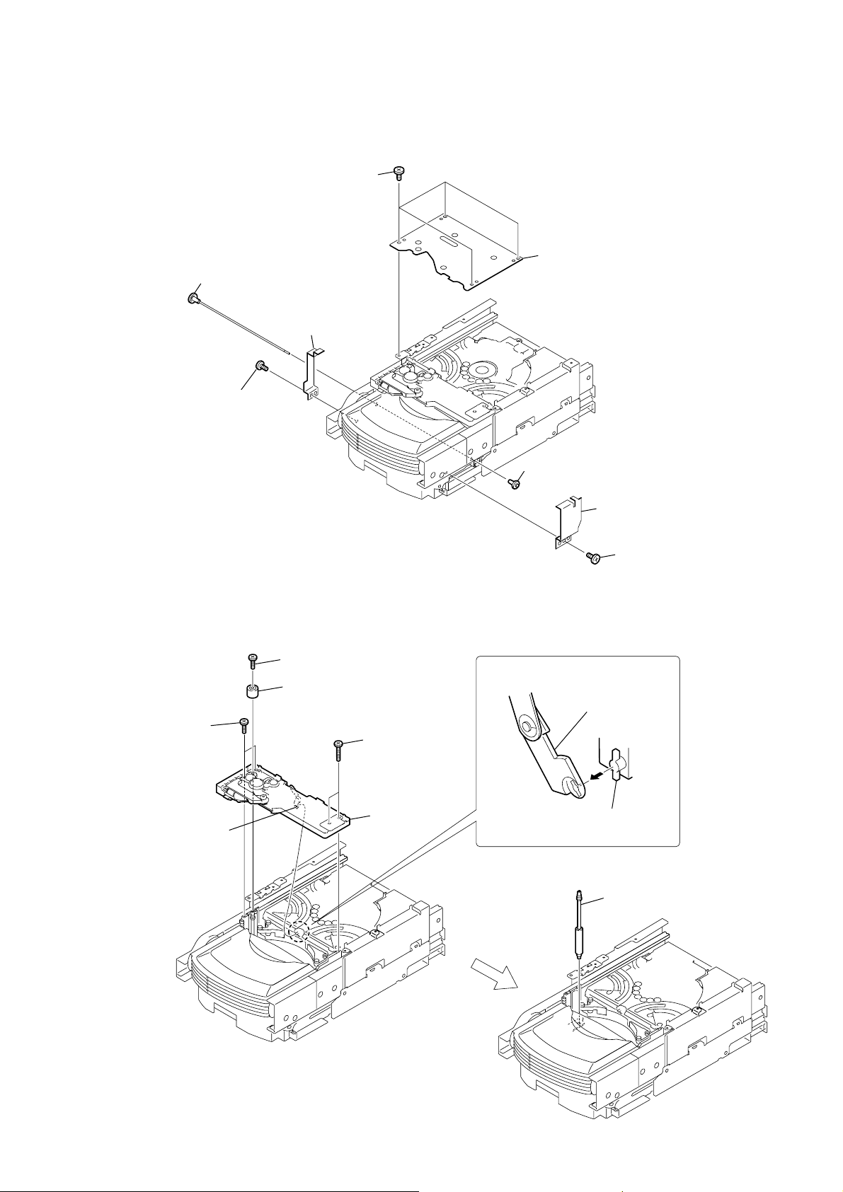
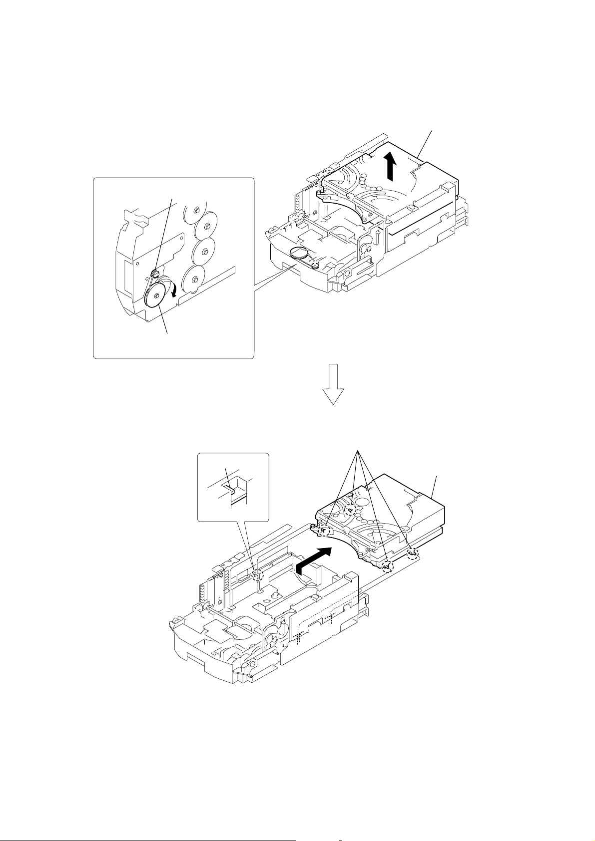
3-30. ROTARY ENCODER
4
Rotate the
the hole on the chassis can be seen
through the plate (comR).
ELV
motor until the position for
plate (com R)
1
three screws
(BTTP M2.6
×
6)
2
RELAY board
6
screw
(PTPWH2.6
8
screw
(PTPWH2.6
0
screw
(PTPWH2.6
qs
screw
(PTPWH2.6
qf
step tapping screw
(PWH2
×
6)
×
×
8)
3
Rotate the ELV motor in
the direction of the arrow.
×
8)
7
×
8)
8)
9
qa
gear (geneva 1)
qd
gear (encoder)
gear (pulley UD)
gear (geneva 2)
28
qg
Remove soldering
from the five points
qj
rotary encoder
qh
two claws
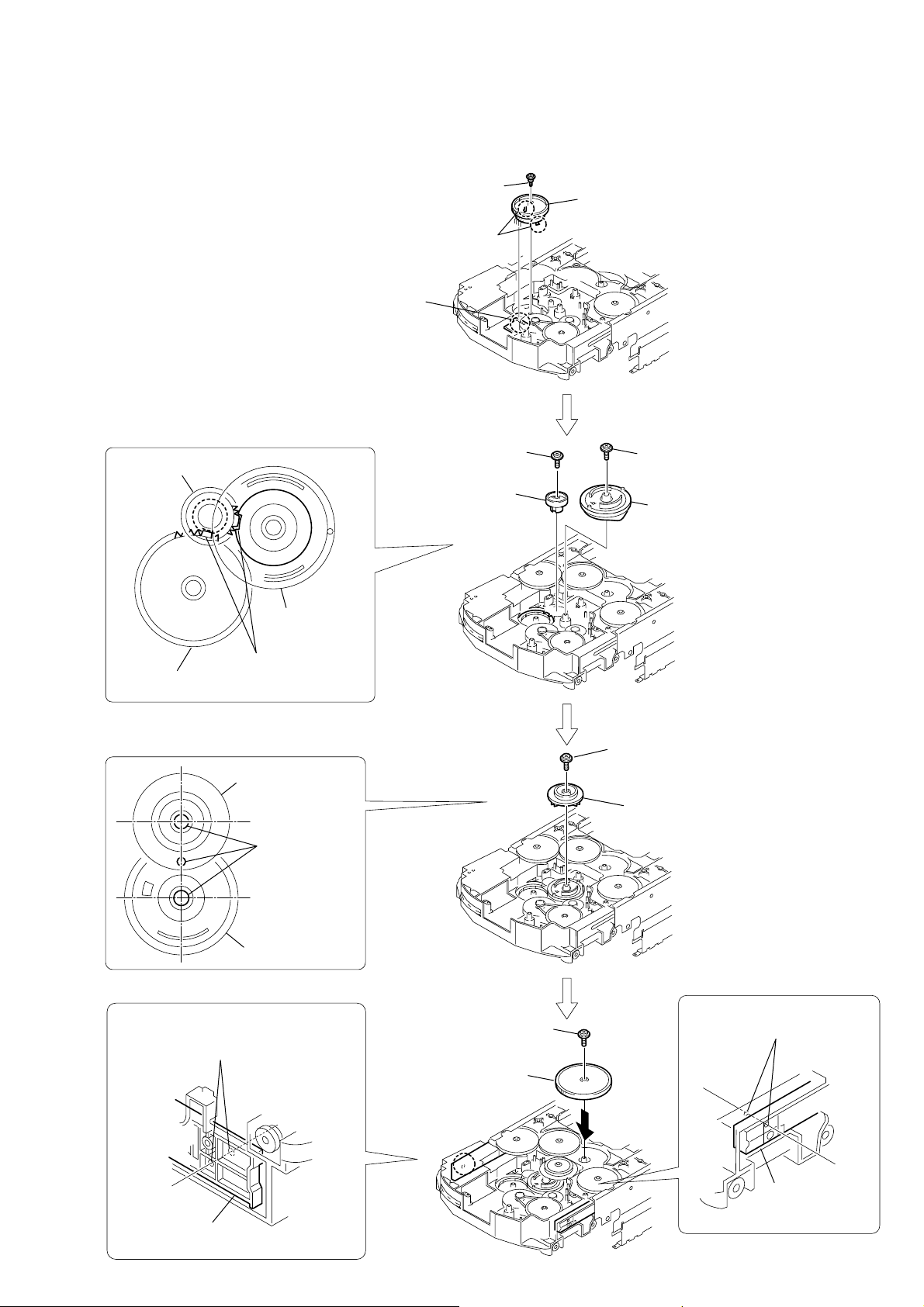
4
screw
(PTPWH2.6
×
8)
1
rotary encoder
2
two claws
3
Apply the soldering
in five points.
9
screw
(PTPWH2.6
×
8)
8
screw
(PTPWH2.6
×
8)
qa
Adjust phases.
7
Adjust phases.
6
gear (geneva 1)
5
gear (encoder)
gear
(geneva 1)
gear (geneva 1)
gear (geneva 2)
rotary encoder
gear (encoder)
qs
screw
(PTPWH2.6
×
8)
0
gear (geneva 2)
qh
screw
(PTPWH2.6
×
8)
qg
gear (pulley UD)
plate (com R)
plate (com L)
qd
Align the plate (com R)
and the chassis hole.
qf
Align the plate (com L)
and the chassis hole.
3-31. ASSEMBLING OF THE ROTARY ENCODER
HCD-HPX7
29
HCD-HPX7
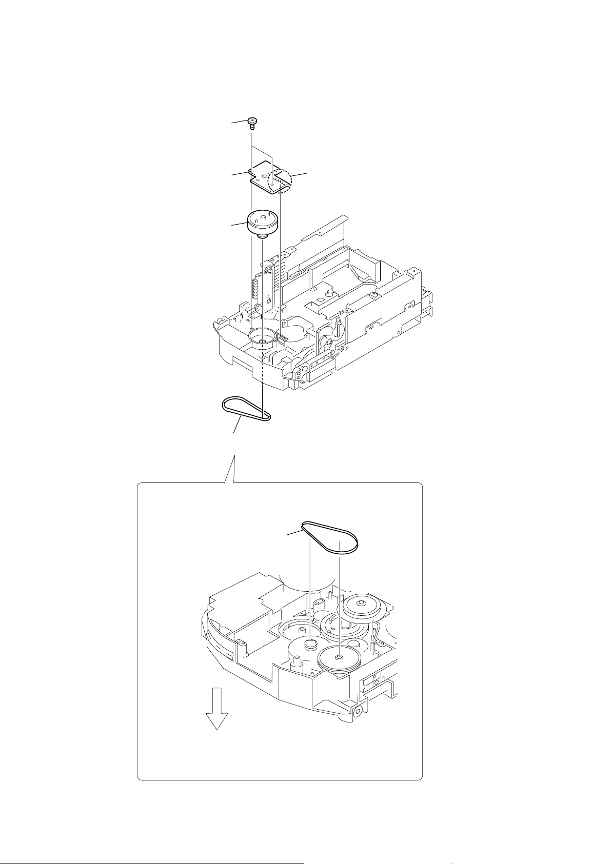
3-32. ELV MOTOR
2
two screws
(BTTP M2.6
4
ELV MOTOR board
5
ELV
×
8)
motor
3
Remove soldering
from the five points
1
belt (MOT-UD)
belt (MOT-UD)
UPPER
SIDE
30
 Loading...