

Sony HCDHDX-265, HCDHDX-267-W, HCDHDX-266, HCDHDX-465, HCDHDX-466 Service manual
...
HCD-HDX265/HDX266/HDX267W/
HDX465/HDX466/HDX665
SERVICE MANUAL
Ver. 1.1 2007.03
Photo: HCD-HDX265
• HCD-HDX265 is the amplifier, DVD
system, tuner and video section in
DAV-HDX265.
• HCD-HDX266 is the amplifier, DVD
system, tuner and video section in
DAV-HDX266.
• HCD-HDX267W is the amplifier, DVD
system, tuner and video section in
DAV-HDX267W.
• HCD-HDX465 is the amplifier, DVD
system, tuner and video section in
DAV-HDX465.
• HCD-HDX466 is the amplifier, DVD
system, tuner and video section in
DAV-HDX466.
• HCD-HDX665 is the amplifier, DVD
system, tuner and video section in
DAV-HDX665.
This product incorporates copyright protection
technology that is protected by U.S. patents and
other intellectual property rights. Use of this
copyright protectio n t echnology must be
authorized by Macrovision, and is intended for
home and other limi ted viewing uses only unless
otherwise authorized by Macrovision. Reverse
engineering or disa ssembly is prohibit ed.
This system incorporates with Dolby* D ig it al
and Dolby Pro Logic (II) adaptive matrix
surround decoder and the DTS** Digital
Surround System.
*Manufactured under license from Dolby
Laboratories.
“Dolby”, “Pro Logic”, and the double-D symbol are
trademarks of Dolby Laboratories.
**Manufactured under license from DTS, Inc.
“DTS” and “DTS Digital Surround” are register ed
trademarks of DTS, Inc.
AUDIO POWER SPECIFICATIONS
for the US model
POWER OUTPUT AND TOTAL HARMONIC
DISTORTION:
With 3 ohms loads, both
channels driven, from 120
- 20,000 Hz; rated 84 watts
per channel minimum
RMS power, with no more
than 0.7 % total harmonic
distortion from 250 milli
watts to rated output.
Amplifier section
EXCEPT HCD-HDX266
US models:
Surround mode (reference) RMS output power
FL/FR/C/SL/SR*: 143 watts
(per chan nel at 3 ohms, 1
kHz, 10 % THD)
Subwoofer*: 285 watts (at
1.5 ohms, 80 Hz, 10 %
THD)
Other models:
Stereo mode (rated) 108 W + 108 W (at 3 ohms,
1 kHz, 1 % THD)
US Model
HCD-HDX265/HDX266/HDX267W/HDX465
Canadian Model
HCD-HDX466/HDX665
E Model
Australian Model
HCD-HDX265
Model Name Using Similar Mechanism HCD-DX155
DVD Mechanism Type CDM81C-DVBU101
Optical Pick-up Block Name KHM-310CAB or
KHM-313CAB
SPECIFICATIONS
Surround mode (reference) RMS output power
FL/FR/C/SL/SR*: 143 watts
(per chan nel at 3 ohms, 1
kHz, 10 % THD)
Subwoofer*: 285 watts (at
1.5 ohms, 80 Hz, 10 %
THD)
HCD-HDX266
Surround mode (reference) RMS output power
FL/FR/C/SL/SR*: 142 watts
(per chan nel at 3 ohms, 1
kHz, 10 % THD)
Subwoofer*: 140 watts (at
3 ohms, 80 Hz, 10 % THD)
*Depending on the sound field settings and the source,
there may be no sound output.
Inputs (Analog)
TV/VIDEO (AUDIO IN) Sensitivity: 450/250 mV
AUDIO IN Sensitivity: 250/125 mV
Outputs (Analog)
Phones Accepts low-and high-
impedance headphones.
– Continued on next page –
9-887-551-02
2007C05-1
© 2007.03
DVD RECEIVER
Sony Corporation
Home Audio Division
Published by Sony Techno Create Corporation

HCD-HDX265/HDX266/HDX267W/HDX465/HDX466/HDX665
DVD system
Laser
Signal format system
North American models: NTSC
Other models: PAL/NTSC
Semiconductor laser
(DVD:λ = 650 nm)
(CD:λ = 790 nm)
Emission duration:
continuous
Tuner section
System PLL quartz-locked digital
FM tuner section
Tuning range
North American models: 87.5-108.0 MHz (100 kHz
Other models: 87.5-108.0 MHz (50 kHz
Antenna (aerial) FM wire antenna (aerial)
Antenna (aerial) terminals 75 ohms, unbalanced
Intermediate frequency 10.7 MHz
AM tuner section
Tuning range
North Americanmodel:
synthesizer
step)
step)
530 − 1,710kHz (with the
interval set at 10 kHz)
531 − 1,710kHz (with the
interval set at 9 kHz)
Australian model:
Other models: 531 − 1,602 kHz (with the
Antenna (aerial) AM loop antenna (aerial)
Intermediate frequency 450 kHz
531 − 1,710 kHz (with the
interval set at 9 kHz)
530 − 1,710 kHz (with the
interval set at 10 kHz)
interval set at 9 kHz)
530 − 1,610 kHz (with the
interval set at 10 kHz)
Video section
Outputs VIDEO: 1 Vp-p 75 ohms
S VIDEO:
Y: 1 Vp-p 75 ohms
C: 0.286 Vp-p 75 ohms
COMPONENT:
Y: 1 Vp-p 75 ohms
PB/CB, PR/CR: 0.7 Vp-p
75 ohms
HDMI OUT: Type A (19
pin)
General
Power requirements
North American models: 120 V AC, 60 Hz
Other models: 220 - 240 V AC, 50/60 Hz
Power output (DIGITAL MEDIA PORT)
Power consumption
EXCEPT HCD-HDX266:
HCD-HDX266: On: 150 W
Dimensions (approx.)
EXCEPT HCD-HDX267W:
HCD-HDX267W: 430 × 86 × 435 mm (17 ×
Mass (approx.)
EXCEPT HCD-HDX267W:
HCD-HDX267W: 5.4 kg (11 lb 15 oz)
Design and specifications are subject to change
without notice.
DC OUT: 5 V, 700 mA
On: 175 W
Standby: 0.3 W (at the
Power Saving mode)
Standby: 0.3 W (at the
Power Saving mode)
430 × 86 × 415 mm (17 ×
1
3
/2 × 16 3/8 inches) (w/h/d)
incl. projecting parts
1
3
/2 × 17 1/4 inches) (w/h/d)
incl. projecting parts
5.2 kg (11 lb 8 oz)
Notes on chip component replacement
• Never reuse a disconnected chip component.
• Notice that the minus side of a tantalum capacitor may be
damaged by heat.
CAUTION
Use of controls or adjustments or performance of procedures
other than those specified herein may result in hazardous radiation
exposure.
SAFETY-RELATED COMPONENT WARNING!!
COMPONENTS IDENTIFIED BY MARK 0 OR DOTTED LINE
WITH MARK 0 ON THE SCHEMATIC DIAGRAMS AND IN
THE PARTS LIST ARE CRITICAL TO SAFE OPERATION.
REPLACE THESE COMPONENTS WITH SONY PAR TS WHOSE
PART NUMBERS APPEAR AS SHOWN IN THIS MANU AL OR
IN SUPPLEMENTS PUBLISHED BY SONY.
2
ATTENTION AU COMPOSANT AYANT RAPPORT
À LA SÉCURITÉ!
LES COMPOSANTS IDENTIFIÉS P AR UNE MARQ UE 0 SUR
LES DIAGRAMMES SCHÉMATIQUES ET LA LISTE DES
PIÈCES SONT CRITIQUES POUR LA SÉCURITÉ DE
FONCTIONNEMENT. NE REMPLACER CES COM- POSANTS
QUE PAR DES PIÈCES SONY DONT LES NUMÉROS SONT
DONNÉS DANS CE MANUEL OU D ANS LES SUPPLÉMENTS
PUBLIÉS PAR SONY.

HCD-HDX265/HDX266/HDX267W/HDX465/HDX466/HDX665
r
SAFETY CHECK-OUT
After correcting the original service problem, perform the following
safety check before releasing the set to the customer:
Check the antenna terminals, metal trim, “metallized” knobs, screws,
and all other exposed metal parts for AC leakage.
Check leakage as described below.
LEAKAGE TEST
The AC leakage from any exposed metal part to earth ground and
from all exposed metal parts to any exposed metal part having a
return to chassis, must not exceed 0.5 mA (500 microamperes.).
Leakage current can be measured by any one of three methods.
1. A commercial leakage tester, such as the Simpson 229 or RCA
WT -540A. Follow the manufactur ers’ instructions to use these
instruments.
2. A battery-operated A C milliammeter . The Data Precision 245
digital multimeter is suitable for this job.
3. Measuring the voltage drop across a resistor by means of a
VOM or battery-operated AC voltmeter . The “limit” indication
is 0.75 V, so analog meters must have an accurate low-v oltage
scale. The Simpson 250 and Sanwa SH-63Trd are examples
of a passive VOM that is suitable. Nearly all battery operated
digital multimeters that have a 2 V A C range are suitable. (See
Fig. A)
To Exposed Metal
Parts on Set
AC
0.15 µF
1.5 k
Ω
Earth Ground
voltmete
(0.75 V)
Fig. A. Using an AC voltmeter to check AC leakage.
SELF DIAGNOSIS FUNCTION
(When letters/numbers appear in the
display)
When the self-di ag nosi s fu nct i on is ac tiv at ed t o
prevent the system from malfunctioning, a 5character servi ce number (e.g., C 13 5 0 ) wi t h a
combination of a le tt er and 4 digits appears on
the TV screen or front panel display. In this case,
check the follo w i ng table.
C:13:50
First 3
characters of
the service
number
C 13 The disc is dirty.
C 31 The disc is not inserte d co rre c tly .
E XX
(xx is a number)
When displaying the version
number on the TV screen
When you turn on the system, the version
number [VER.X.XX] (X is a number) may
appear on the TV scree n. Alt ho ugh this is not a
malfunction and for Sony service use only,
normal system operation will not be possible.
Turn off the system, a nd the n turn o n the system
again to operate.
Cause and/or corrective action
,Clean the disc with a soft cloth.
,Restart the system, the n re-insert
the disc correctly.
To prevent a malfunction, the
system has performed the s el fdiagnosis function.
,Contact your nearest Sony
dealer or local authorized So ny
service facility and give the 5character service number.
Example: E 61 10
VER.X.XX
3

HCD-HDX265/HDX266/HDX267W/HDX465/HDX466/HDX665
TABLE OF CONTENTS
1. SERVICING NOTES ............................................... 5
2. GENERAL ................................................................... 9
3. DISASSEMBLY
3-1. Disassembly Flow ........................................................... 11
3-2. Case ................................................................................. 12
3-3. DIAT CON Board............................................................ 12
3-4. IO Board .......................................................................... 13
3-5. Front Panel Block ............................................................ 13
3-6. POWER Board ................................................................ 14
3-7. Back Panel Block ............................................................ 14
3-8. DMPORT Board.............................................................. 15
3-9. MAIN Board.................................................................... 15
3-10. Cover (MD) ..................................................................... 16
3-11. DVD Mechanism deck (CDM81C-DVBU101) .............. 16
3-12. Tray (Main) Assy............................................................. 17
3-13. MOTOR Board ................................................................ 17
3-14. Base Unit (DVBU101) .................................................... 18
3-15. Optical Pick-Up Block (KHM-310CAB/313CAB) ........ 18
3-16. Gear (Sub Tray 1)/Gear (Sub Tray 2).............................. 19
3-17. Lever Assy ....................................................................... 19
3-18. Stocker Section ................................................................ 20
3-19. Cam (Stocker).................................................................. 20
3-20. Gear (Stocker 3) .............................................................. 21
3-21. Rotary Encoder (MD) ...................................................... 21
3-22. Gear (BU1) ...................................................................... 22
6-29. Printed Wiring Board – IO Board –................................. 58
6-30. Printed Wiring Board – FL Board – ................................ 59
6-31. Schematic Diagram – FL Board (1/2) – .......................... 60
6-32. Schematic Diagram – FL Board (2/2) – .......................... 61
6-33. Printed Wiring Boards – PANEL Section –..................... 62
6-34. Schematic Diagram – PANEL Section –......................... 63
6-35. Schematic Diagram – POWER Board (1/2) – ................. 64
6-36. Schematic Diagram – POWER Board (2/2) – ................. 65
6-37. Printed Wiring Board – POWER Board – ....................... 66
7. EXPLODED VIEWS
7-1. Case Section .................................................................... 87
7-2. Front Panel Section ......................................................... 88
7-3. Main Section.................................................................... 89
7-4. DVD Mechanism Deck Section-1
(CDM81C-DVBU101) .................................................... 90
7-5. DVD Mechanism Deck Section-2
(CDM81C-DVBU101) .................................................... 91
7-6. DVD Mechanism Deck Section-3
(CDM81C-DVBU101) .................................................... 92
7-7. Base Unit ......................................................................... 93
8. ELECTRICAL PARTS LIST................................ 94
4. TEST MODE.............................................................. 23
5. ELECTRICAL ADJUSTMENTS ......................... 28
6. DIAGRAMS
6-1. Block Diagram – RF SERVO/VIDEO Section – ............ 29
6-2. Block Diagram
– CHANGER/HDMI/DMPORT Section – ..................... 30
6-3. Block Diagram – AUDIO Section – ................................ 31
6-4. Block Diagram – AMP Section – .................................... 32
6-5. Block Diagram
– PANEL/POWER SUPPLY Section – ........................... 33
6-6. Schematic Diagram – MAIN Board (1/13) – .................. 35
6-7. Schematic Diagram – MAIN Board (2/13) – .................. 36
6-8. Schematic Diagram – MAIN Board (3/13) – .................. 37
6-9. Schematic Diagram – MAIN Board (4/13) – .................. 38
6-10. Schematic Diagram – MAIN Board (5/13) – .................. 39
6-11. Schematic Diagram – MAIN Board (6/13) – .................. 40
6-12. Schematic Diagram – MAIN Board (7/13) – .................. 41
6-13. Schematic Diagram – MAIN Board (8/13) – .................. 42
6-14. Schematic Diagram – MAIN Board (9/13) – .................. 43
6-15. Schematic Diagram – MAIN Board (10/13) – ................ 44
6-16. Schematic Diagram – MAIN Board (11/13) – ................ 45
6-17. Schematic Diagram – MAIN Board (12/13) – ................ 46
6-18. Schematic Diagram – MAIN Board (13/13) – ................ 47
6-19. Printed Wiring Board
– MAIN Board (Component Side) – ............................... 48
6-20. Printed Wiring Board
– MAIN Board (Conductor Side) – ................................. 49
6-21. Printed Wiring Board – SIRIPARA Board – ................... 50
6-22. Schematic Diagram – SIRIPARA Board –...................... 51
6-23. Printed Wiring Boards – CHANGER Section –.............. 52
6-24. Schematic Diagram – CHANGER Section – .................. 53
6-25. Printed Wiring Board – DMPORT Board – .................... 54
6-26. Schematic Diagram – DMPORT Board – ....................... 55
6-27. Schematic Diagram – IO Board (1/2) –........................... 56
6-28. Schematic Diagram – IO Board (2/2) –........................... 57
4

HCD-HDX265/HDX266/HDX267W/HDX465/HDX466/HDX665
FRONT R
CENTER WOOFER
FRONT L SUR R SUR L
MONITOR OUT
TV/VIDEO
ANTENNA
SPEAKER
DIR-TC1
SPEAKER
COMPONENT VIDEO OUT
COAXIAL
AM
FM
75
RLAUDIO IN
YPB/CBPR/C
VIDEO
(DVD ONLY)
S VIDEO
(DVD ONLY)
(DVD O
OUT
DMPORT
PART No.
SECTION 1
SERVICING NOTES
NOTES ON HANDLING THE OPTICAL PICK-UP
BLOCK OR BASE UNIT
The laser diode in the optical pick-up block may suffer electrostatic
break-down because of the potential difference generated by the
charged electrostatic load, etc. on clothing and the human body.
During repair, pay attention to electrostatic break-down and also
use the procedure in the printed matter which is included in the
repair parts.
The flexible board is easily damaged and should be handled with
care.
NOTES ON LASER DIODE EMISSION CHECK
The laser beam on this model is concentrated so as to be focused on
the disc reflective surface by the objective lens in the optical pickup block. Therefore, when checking the laser diode emission,
observe from more than 30 cm away from the objective lens.
UNLEADED SOLDER
Boards requiring use of unleaded solder are printed with the leadfree mark (LF) indicating the solder contains no lead.
(Caution: Some printed circuit boards may not come printed with
the lead free mark due to their particular size)
: LEAD FREE MARK
Unleaded solder has the following characteristics.
• Unleaded solder melts at a temperature about 40 °C higher
than ordinary solder.
Ordinary soldering irons can be used but the iron tip has to be
applied to the solder joint for a slightly longer time.
Soldering irons using a temperature regulator should be set to
about 350 °C.
Caution: The printed pattern (copper foil) may peel away if
the heated tip is applied for too long, so be careful!
• Strong viscosity
Unleaded solder is more viscou-s (sticky, less prone to flow)
than ordinary solder so use caution not to let solder bridges
occur such as on IC pins, etc.
• Usable with ordinary solder
It is best to use only unleaded solder but unleaded solder may
also be added to ordinary solder.
NOTE OF REPLACING THE EEPROM (IC1103) ON
THE MAIN BOARD
EEPROM (IC1103) on the MAIN board cannot exchange with
single. When EEPROM (IC1103) on the MAIN board is damaged,
exchange the entire mounted board.
MODEL IDENTIFICATION
MODEL PART No.
HDX465 2-892-557-2[]
HDX265: US model 2-892-557-3[]
HDX265: Australian model 2-892-557-4[]
HDX665 2-892-557-5[]
HDX466 2-892-557-6[]
HDX266 2-892-557-8[]
HDX267W 2-892-557-9[]
HDX265: E model 3-100-747-1[]
RELEASING THE TRAY LOCK
The disc tray lock function for the antitheft of an demonstration
disc in the store is equipped.
Releasing Procedure :
1. Press the
I/1 button to turn on the system.
2. Press the FUNCTION button repeatedly to select “DVD”.
3. While pressing the x button, press the A button until
“UNLOCKED” displayed on the fluorescent indicator tube
(around 5 seconds).
Note: When “LOCKED” is displayed, the tray lock is not released by turning
power on/off with the I/1 button.
RELEASING THE DEMO PLAY LOCK
Releasing Procedure :
1. Press the I/1 button to turn on the system.
2. Press the FUNCTION button repeatedly to select “DVD”.
3. While pressing the x button, press the H button until
“DEMO OFF” displayed on the fluorescent indicator tube
(around 5 seconds).
Note: When “DEMO PLAY” is displayed, the set is not possible to turn off
the system.
5
HCD-HDX265/HDX266/HDX267W/HDX465/HDX466/HDX665
About This Manual
•The instruc tions in this manual describe the
controls on the remote. You can also use the
controls on the unit if they have the same or
similar names as those on the remote.
•The instructions in this manual are for HCD-
HDX265, HCD-HDX266, HCD-HDX267W,
HCD-HDX465, HCD-HDX466 and HCDHDX665. HCD-HDX265 is the model used
for illustration purposes. Any difference in
operation is clearly indicated in the text, for
example, “HCD-HDX265 only.”
•The Control Menu item s m ay var y depending
on the area.
•“DVD” may be used as a general term for
DVD VIDEOs, DVD+RWs/DVD+Rs, and
DVD-RWs/DVD-Rs.
•Measurements are expressed in feet (ft) for
North American models.
•The following symbols are used in this
manual.
Symbol Meaning
Functions available for DVD
VIDEOs, DVD-Rs/DVD-RWs in
video mode, and DVD+Rs/
DVD+RWs
Functions available for DVD-Rs/
DVD-RWs in VR (Video
Recording) mode
Functions available for VIDEO
CDs (including Super VCDs or CDRs/CD-RWs in video CD format or
Super VCD format)
Functions available for music CDs
or CD-Rs/CD-R Ws in music CD
format
Functions available for DATA CDs
(CD-ROMs/CD-Rs/CD-RWs)
containing MP3
JPEG image files, and DivX
video files
Functions available for DATA
DVDs (DVD-ROMs/DVD-Rs/
DVD-RWs/DVD+Rs/DVD+RWs)
containing MP3
JPEG image files, and DivX
video files
1)
MP3 (MPEG1 Audio Layer 3) is a standard format
defined by ISO/MPEG which compresses audio data.
2)
Except for United Kingdom and North American
models.
3)
DivX® is a video file comp r ession technology ,
developed by DivX, Inc.
4)
DivX, DivX Certified, and associated log os are
trademarks of DivX, Inc. and are used u n der license.
1)
audio tracks,
1)
audio tracks,
2)3)4)
2)3)4)
This System Can Play the
Following Discs
Format of
discs
DVD VIDEO
DVD-RW/
DVD-R
6
Disc logo
DVD+RW/
DVD+R
VIDEO CD
(Ver. 1.1 and
2.0 discs)/
Audio CD
CD-RW/CD-R
(audio data)
(MP3 files)
(JPEG files)
“DVD-RW,” “DVD+RW,” “DVD+R,”
“DVD VIDEO,” and the “CD” logos are trademarks.
Note about CDs/DVDs
The system can play C D -ROMs/CD-Rs/ C D RWs recorded in the following form ats:
− audio CD format
− VIDEO CD format
− MP3 audio tracks, JPEG image files, and
DivX video files* of form at conforming to
ISO 9660 Level 1/Level 2, or its extended
format, Joliet
The system can play DVD-ROMs/DVD+RWs/
DVD-RWs/DVD+Rs/DVD-Rs recorded in the
following formats:
− MP3 audio tracks, JPEG image files, and
DivX video files* of format conforming to
UDF (Universal Disc Format)
*Except for United Kingdom and North American
models.
Example of discs that the
system cannot play
The system cannot play the following discs:
• CD-ROMs recorded in PHOTO CD format
• Data part of CD-Extras
• DVD Audios
• Super Audio CD
• DATA DVDs that do not contain MP3 audio
tracks, JPEG image files, or DivX video files*
*Except for United Kingdom and North American
models.
• DVD-RAMs
Also, the system cannot play the following
discs:
• A DVD VIDEO with a different region code
• A disc that has a non-standard shape (e.g.,
card, heart)
• A disc with paper or stickers on it
• A disc that has the adhe sive of celloph ane tap e
or a sticker still left on it
Notes about CD-R/CD-RW/DVD-R/
DVD-RW/DVD+R/DVD+RW
In some cases, CD-R/CD-RW/DVD-R/DVDRW/DVD+R/DVD+RW cannot be played on
this system due to the recording qual ity or
physical condition of the disc, or the
characteristics of the recording device and
authoring software.
The disc will n ot play if it has not been corre ctly
finalized. For more information, see the
operating instructions for the recording device.
Note that some playback functions may not
work with some DVD+RWs/DVD+Rs, even if
they have been correctly finalized. In this case,
view the disc by normal playback. Also some
DATA CDs/DATA DVDs created in Packet
Write format cannot be played.
Music discs encoded with
copyright protection
technologies
This product is designed to pl ay back discs that
conform to the Compact Disc (CD) standard.
Recently, various music discs encoded with
copyright protection technologies are marketed
by some record companies. Please be aware that
among those discs, t here are some that do not
conform to the CD standard and may not be
playable by this product.
Note on DualDiscs
A DualDisc is a two sided di sc product which
mates DVD recorded material on one side with
digital audio material on the other side.
However, since th e audi o materi al side doe s not
conform to the Compact Disc (CD) standard,
playback on this product is not guaranteed.
About Multi Session CD
•This system can play Multi Session CDs when
an MP3 audio track is contained in the first
session. Any subsequent MP3 audio t racks
recorded in later sessions can also be played
back.
•This system can play Multi Session CDs when
a JPEG image file is contained in the first
session. Any subsequent JPEG ima ge files
recorded in later sessions can also be played
back.
•If audio tracks a nd images in mus ic CD format
or video CD format are recorded in the first
session, only the first session will be played
back.
Region code
Your system has a region code prin t ed on the
rear of the unit an d will on ly play DVDs labele d
with the same region code.
DVD VIDEOs labeled will also pla y on this
ALL
system.
If you try to play any other DVD VIDEO, the
message [Playback prohibited by area
limitations.] will appear on the TV screen.
Depending on the DVD VIDE O, no re gion co de
indication may be given even though playi ng the
DVD VIDEO is prohibited by area restrictions.
Note about playback
operations of DVDs and
VIDEO CDs
Some playback operations of DVDs and VIDEO
CDs may be intentionally set by software
producers. Since th is system plays DVD s and
VIDEO CDs according to the disc contents the
software producers designed, some playback
features may not be available. Be sure to read the
operating instructions supplied with the DVDs
or VIDEO CDs.

HCD-HDX265/HDX266/HDX267W/HDX465/HDX466/HDX665
HOW TO IDENTIFY OPTICAL PICK-UP BLOCK
Note: There are two kinds of OPTICAL PICK-UP BLOCK in this set.
When replacing the OPTICAL PICK-UP BLOCK, make sure which
OPTICAL PICK-UP BLOCK it is following the “How to Identify”
in the figure shown below.
OPTICAL PICK-UP BLOCK
Printed of KHM-310CAB or KHM-313CAB.
HOW TO OPEN THE TRAY WHEN POWER SWITCH TURN OFF
Turn gear (BU1) from a hole at the bottom,
and pull out a tray.
gear (BU1)
tray
7
HCD-HDX265/HDX266/HDX267W/HDX465/HDX466/HDX665
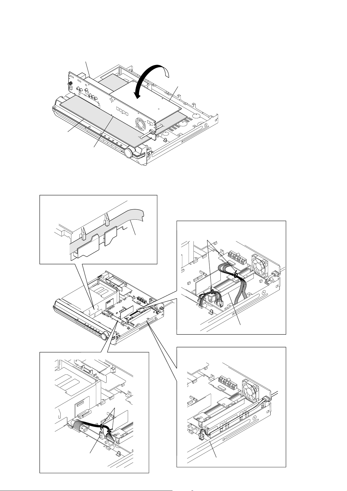
MAIN BOARD SERVICE POSITION
1
Remove the back panel with
2
IO board
insulation sheet
back panel
Remove the MAIN board.
3
Assemble the MAIN board to back panel block.
4
Reverse the back panel block.
MAIN board
IO board
.
HARNESS SETTING
flexible wire
lead pin
Check not touch the heat sink.
lead pin
Check not touch
the heat sink.
Check not touch the chassis.
8
HCD-HDX265/HDX266/HDX267W/HDX465/HDX466/HDX665
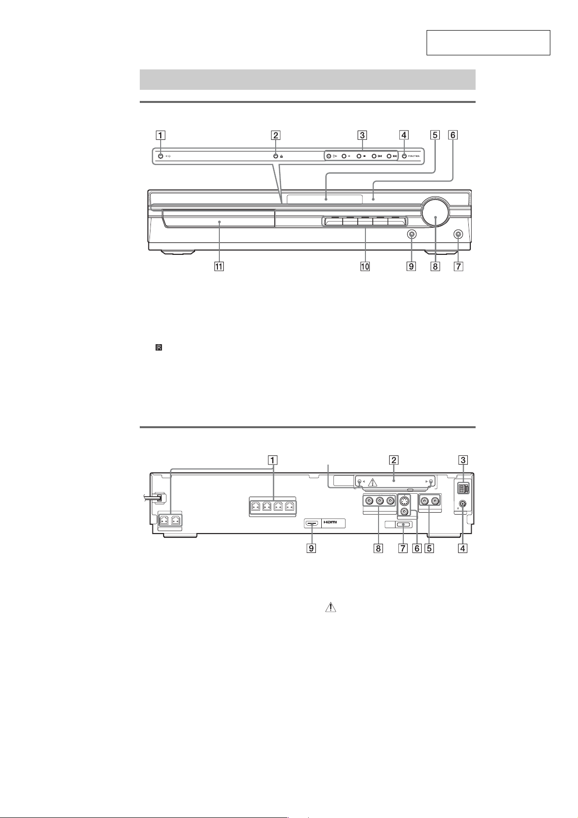
SECTION 2
Index to Parts and Controls
Front panel
GENERAL
This section is extracted from
instruction manual.
A "/1 (on/standby)
B A (open/close)
C Disc operation
D FUNCTION
E Front panel display
F (remote sensor)
G PHONES jack
Rear panel
CENTER WOOFER
SPEAKER
FRONT R
FRONT L SUR R SUR L
SPEAKER
H VOLUME control
I AUDIO IN/A.CAL MIC jack
J DISC 1-5 buttons/indicators
K Disc tray
Screws*
DIR-TC1
YPB/CBPR/C
R
S VIDEO
(DVD ONLY)
(DVD ONLY)
COMPONENT VIDEO OUT
OUT
DMPORT
MONITOR OUT
(DVD ONLY)
VIDEO
RLAUDIO IN
TV/VIDEO
AM
FM
75
ANTENNA
COAXIAL
A SPEAKER jacks
B DIR-TC1 slot for the WAHT-SD1
C AM terminal
D FM 75 Ω COAXIAL jack
E TV/VIDEO (AUDIO IN R/L) jacks
F MONITOR OUT (S VIDEO/VIDEO) jacks
G DMPORT (DIGITAL MEDIA PORT) jack
H COMPONENT VIDEO OUT jacks
I HDMI OUT jack
*
CAUTION
Please do not remove the screws before
installing the WAHT-SD1.
9
HCD-HDX265/HDX266/HDX267W/HDX465/HDX466/HDX665
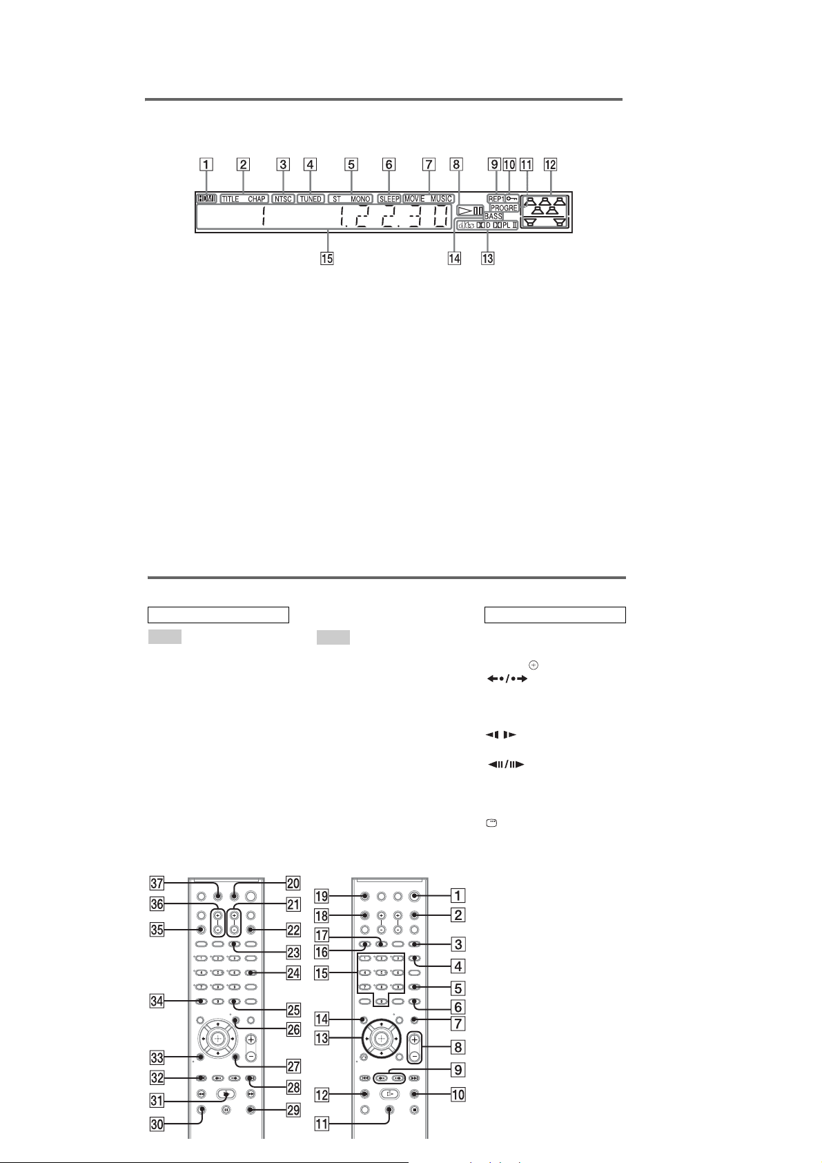
Front panel display
About the indications in the front panel display
A Lights up when the HDMI OUT jack is
correctly connected to HDCP (highbandwidth digital content protection)
compliant device with HDMI or DVI
(digital visual interface) input.
B Lights up when the time information of
a title or chapter appears in the front
panel display. (DVD only)
C Lights up when the color system is set
to NTSC. (Asian, Australian, and Middle
Eastern models only)
D Lights up when a station is received.
(Radio only)
E Stereo/Monaural effect (Radio only)
F Lights up when the sleep timer is set.
G Lights up when t he movie or music
mode is selected.
Remote control
ALPHABETICAL ORDER
A – O
ANGLE 5
AUDIO 4
CLEAR ef
D.TUNING wf
DISC SKIP eg
DISPLAY 2
DVD MENU wh
DVD TOP MENU qf
DYNAMIC BASS wd
ENTER wg
FUNCTION ws
MOVIE/MUSIC qj
MUTING 7
Number buttons* qg
P – Z
PICTURE NAVI 6
PRESET +/− wk es
SOUND FIELD qh
SUBTITLE wf
SYSTEM MENU wg
THEATRE SYNC w;
TUNING +/− 0 qs
TV e;
TV CH +/− wa
TV INPUT qk
TV VOL +/− eh
VIDEO FORMAT 3
VOLUME +/−* 8
H Playing status (DVD function only)
I Current repeat mode
J Lights up when the child lock fu nc t ion
is set to on.
K Lights up when the system outputs
progressive signals (DVD function
only).
L Indicates the selected [SPEAKER
FORMATION].
M Current surround format (Except for
JPEG)
N Lights up when the DYNAMIC BASS is
selected.
O Displays system’s status such as
chapter, title, or track number, time
information, radio frequency, playing
status, sound field, etc.
BUTTON RESCRIPTIONS
[/1 (on/standby) 1
TV [/1 (on/standby) ej
C/X/x/c/ qd
REPLAY/
ADVANCE 9
./> es wk
m/M qs 0
SLOW qs 0
H (play)* ea
STEP 9
x (stop) wl
X (pause) qa
Z (open/close) ql
DISPLAY wj
O RETURN ed
-/-- ef
10
*The H, number 5, and
VOLUME + buttons have
tactile dots. Use t he tact ile dot s
as references when operating
the system.

HCD-HDX265/HDX266/HDX267W/HDX465/HDX466/HDX665
SECTION 3
DISASSEMBLY
• This set can be disassembled in the order shown below.
3-1. DISASSEMBLY FLOW
Note 1: The process described in can be performed in any order.
Note 2: Without completing the process described in , the next process can not be performed.
SET
3-2. CASE
(Page 12)
3-3. DIAT CON BOARD
(Page 12)
3-4. IO BOARD
(Page 13)
3-5. FRONT PANEL BLOCK
(Page 13)
3-10. COVER (MD)
(Page 16)
3-11. DVD MECHANISM DECK
(CDM81C-DVBU101)
(Page 16)
3-12. TRAY (MAIN) ASSY
(Page 17)
3-14. BASE UNIT
(DVBU101)
(Page 18)
3-6. POWER BOARD
(Page 14)
3-13. MOTOR BOARD
(Page 17)
3-7. BACK PANEL BLOCK
(Page 14)
3-8. DMPORT BOARD
(Page 15)
3-9. MAIN BOARD
(Page 15)
3-15. OPTICAL PICK-UP BLOCK
(KHM-310CAB/313CAB)
(Page 18)
3-16. GEAR (SUB TRAY 1)/
GEAR (SUB TRAY 2)
(Page 19)
3-17. LEVER ASSY
(Page 19)
3-18. STOCKER SECTION
(Page 20)
3-19. CAM (STOCKER)
(Page 20)
3-20. GEAR (STOCKER 3)
(Page 21)
3-21. ROTARY ENCODER (MD)
(Page 21)
3-22. GEAR (BU1)
(Page 22)
11
HCD-HDX265/HDX266/HDX267W/HDX465/HDX466/HDX665
)
Note: Follow the disassembly procedure in the numerical order given.
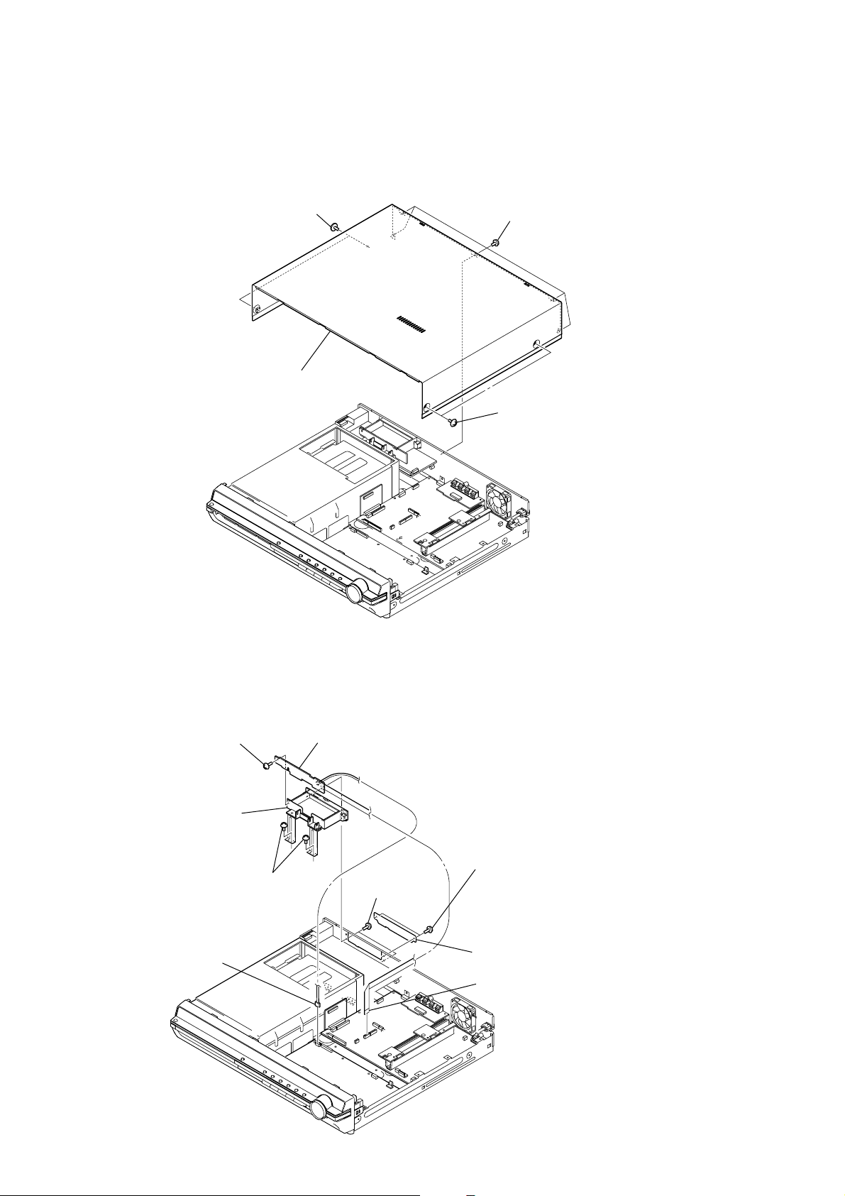
3-2. CASE
1
two screws
(case 3 TP2)
4
case
2
five screws
(BV3 )
3
two screws
(case 3 TP2
3-3. DIAT CON BOARD
8
7
case (diat)
2
connector
(CN903)
screw
(BV3)
6
two screws
(BV3)
9
DIAT CON board
5
two screws
(BV3)
3
two screws
(BV3)
4
lid (diat-P)
1
flexible flat cable (11 core)
(CN651)
12

3-4. IO BOARD
)
)
4
flexible flat cable (9 core)
(CN201)
5
flexible flat cable (11 core)
(CN4302)
3
tuner (FM/AM)
0
connector
(CN302)
2
two screws
(BVTT2.6
HCD-HDX265/HDX266/HDX267W/HDX465/HDX466/HDX665
1
flexible flat cable (9 core)
(tuner)
9
qa
IO board
flexible flat cable (19 core
7
(CN606)
6
flexible flat cable (5 core)
×
6)
(CN702)
8
four screws
(BV3)
3-5. FRONT PANEL BLOCK
3
loading panel
1
Turn gear (BU1) from a hole at the bottom,
and pull out a tray.
(HDX665)
8
screw
(BV3)
0
three screws
(BV3)
gear (BU1)
9
screw (BV3)
(HDX665)
qa
front panel block
4
flexible flat cable (23 core)
(CN501)
5
6
shield plate (H/P
7
connector (CN3001)
two screws
(PWH3
×
8)
2
Open the tray.
13

HCD-HDX265/HDX266/HDX267W/HDX465/HDX466/HDX665
k
3-6. POWER BOARD
2
1
8
two screws
(PWH3
connector
(CN903)
3
connector
(CN907)
×
8)
0
POWER board
connector
(CN906)
6
two screws
(PWH3
×
8)
7
shield plate (H/P)
4
connector
(CN901)
5
connector
(CN3002)
9
PC board holder
3-7. BACK PANEL BLOCK
2
flexible flat cable (11 core)
(CN4302)
1
flexible flat cable (9 core)
(CN201)
6
connector
(CN903)
9
two screws
(BV3)
0
screw (BV3)
qg
qa
screw (B3 × 6)
qs
screw (BV3)
qj
back panel bloc
qd
screw
(BV3)
14
5
flexible flat cable
(19 core) (CN606)
4
flexible flat cable (5 core)
(CN702)
3
flexible flat cable (11 core)
(CN651)
7
8
connector (CN901)
qh
connector
(CN302)
connector
(CN3000)
qf
two screws
(BV3)

3-8. DMPORT BOARD
qj
two screws
(BV3)
5
connector
(CN625)
qd
connector
(CN906)
4
wire (flat type) (21 core)
(CN626)
6
SIRIPARA board
qf
connector
(CN1201)
qk
four screws
(BV3)
7
screw
(BVTP3
×
12)
8
two screws
(BV3)
9
heat sink (AMP)
qa
wire (flat type)
(24 core)
(CN1101)
0
two radiation sheets
2
two screws
(BV3)
3
SPEAKER board
1
connector (CN780)
ql
two screws
(BV3)
w;
MAIN board
qg
connector
(CN3002)
qh
connector
(CN3001)
qs
wire (flat type)
(23 core)
(CN501)
HCD-HDX265/HDX266/HDX267W/HDX465/HDX466/HDX665
2
two screws
(BV3)
1
connector
(CN203)
3
DMPORT board
3-9. MAIN BOARD
15

HCD-HDX265/HDX266/HDX267W/HDX465/HDX466/HDX665
)
3-10. COVER (MD)
1
four screws
(BV3)
2
cover (MD)
3-11. DVD MECHANISM DECK (CDM81C-DVBU101)
5
DVD mechanism deck
(CDM81C-DVBU101)
4
five screws
(BVTP3
×
10)
2
flexible flat cable (21 core)
(CN626)
3
connector
(CN1201)
1
flexible flat cable (24 core
(CN1101)
16

3-12. TRAY (MAIN) ASSY
)
2
two screws
(BTTP M2.6)
tray (main) assy
5
HCD-HDX265/HDX266/HDX267W/HDX465/HDX466/HDX665
1
3
bracket (top)
4
two screws
(BTTP M2.6
3-13. MOTOR BOARD
7
Remove two solders.
8
motor (81) assy (BU U/D motor)
(M762 )
1
screw
(BTTP M2.6)
2
bracket
3
screw
(BTTP M2.6)
4
MOTOR board
5
Remove two solders.
6
motor (81) assy (LD/ST motor)
(M761)
17

HCD-HDX265/HDX266/HDX267W/HDX465/HDX466/HDX665
s
)
3-14. BASE UNIT (DVBU101)
1
(PTPWH M2.6)
3
base unit (DVBU101)
2
floating screw
(PTPWH M2.6)
two floating screw
3-15. OPTICAL PICK-UP BLOCK (KHM-310CAB/313CAB)
3
insulator screw
9
insulator
4
insulator screw
0
insulator
5
qa
insulator
7
insulator screw
qs
insulator
8
insulator screw
qd
optical pick-up block
(KHM-310CAB/313CAB
6
holder (310) assy
18
2
three screws
(BTTP 2.6)
1
two screws
(BTP2.6
×
8)

HCD-HDX265/HDX266/HDX267W/HDX465/HDX466/HDX665
3-16. GEAR (SUB TRAY 1)/GEAR (SUB TRAY 2)
PRECAUTION DURING GEAR (SUB TRAY 1/2) INSTALLATION
Align the marks of the gears as shown in the illustration.
4
(sub tray 1)
gear (sub tray 2)
gear (sub tray 1)
gear (sub tray 2)
3
1
(PTPWH2.6
three gears
gear (sub tray 2)
five screws
×
8)
2
gear (sub tray 2)
3-17. LEVER ASSY
Before re-assembling, align the lever (release)
and the lever (sub tray) with the lever (mode)
as shown in the illustration.
dowel dowel
lever (mode)
lever (release)
lever (sub tray)
When re-assembling, insert the lever (sub tray)
between the bosses of the shutter (tray).
5
6
lever (release)
3
floating screw
(PTPWH M2.6)
shutter (tray)
boss
boss
lever (sub tray)
lever (sub tray)
4
1
screw
(PTPWH2.6
2
7
lever (mode)
×
8)
shutter (tray)
Before re-assembling, slide the cam (BU)
in the direction of the arrow.
cam (BU)
19

HCD-HDX265/HDX266/HDX267W/HDX465/HDX466/HDX665
3-18. STOCKER SECTION
1
Rotate the gear (SS3) in the
direction of the arrow.
2
stocker section
3-19. CAM (STOCKER)
PRECAUTION DURING CAM (STOCKER) INSTALLATION
Before installing the cams (stocker), fix the gear (stocker 3) in
the manner so that the hole of the gear (stocker 3) should be
aligned with the hole of the chassis located beneath
the gear (stocker 3). Be sure to install the cams (stocker) in
such a way that the grooves of the cams (stocker) face
the direction of the arrows.
cam (stocker)
gear
(stocker 2)
gear (stocker 3)
cam (stocker)
gear
(stocker 2)
hole
gear
(stocker 2)
cam (stocker)
1
floating screw
(PTPWH M2.6)
3
hook
7
screw
(PTPWH2.6
8
cam
(stocker)
4
lever (SW)
2
tension spring (SW)
5
two screws
(PTPWH2.6
6
×
8)
two cams
(stocker)
×
8)
20

3-20. GEAR (STOCKER 3)
1
step tapping screw
(PWH 2
×
6)
2
gear (stocker 3)
gear (stocker 3)
(reverse-side)
rotary encoder
(ST U/D encoder)
PRECAUTION DURING GEAR (STOCKER 3) INSTALLATION
Be sure to align the rib of the gear (stocker 3) with the groove
of the rotary encoder.
groove
rib
HCD-HDX265/HDX266/HDX267W/HDX465/HDX466/HDX665
3-21. ROTARY ENCODER (MD)
PRECAUTION DURING ROTARY ENCODER (MD) INSTALLATION
Slide the cam (BU) in the direction of the arrow so that the mark
of the gear (BU1) can be seen. Engage the gears while aligning
the mark of the gear (BU1) with the protruding part of the
rotary encoder.
cam (BU)
rotary encoder (MD)
protruding part
mark
gear (BU1)
1
three screws
(BTTP M2.6)
2
rotary encoder (MD)
– CD mechanism deck bottom view –
21
HCD-HDX265/HDX266/HDX267W/HDX465/HDX466/HDX665
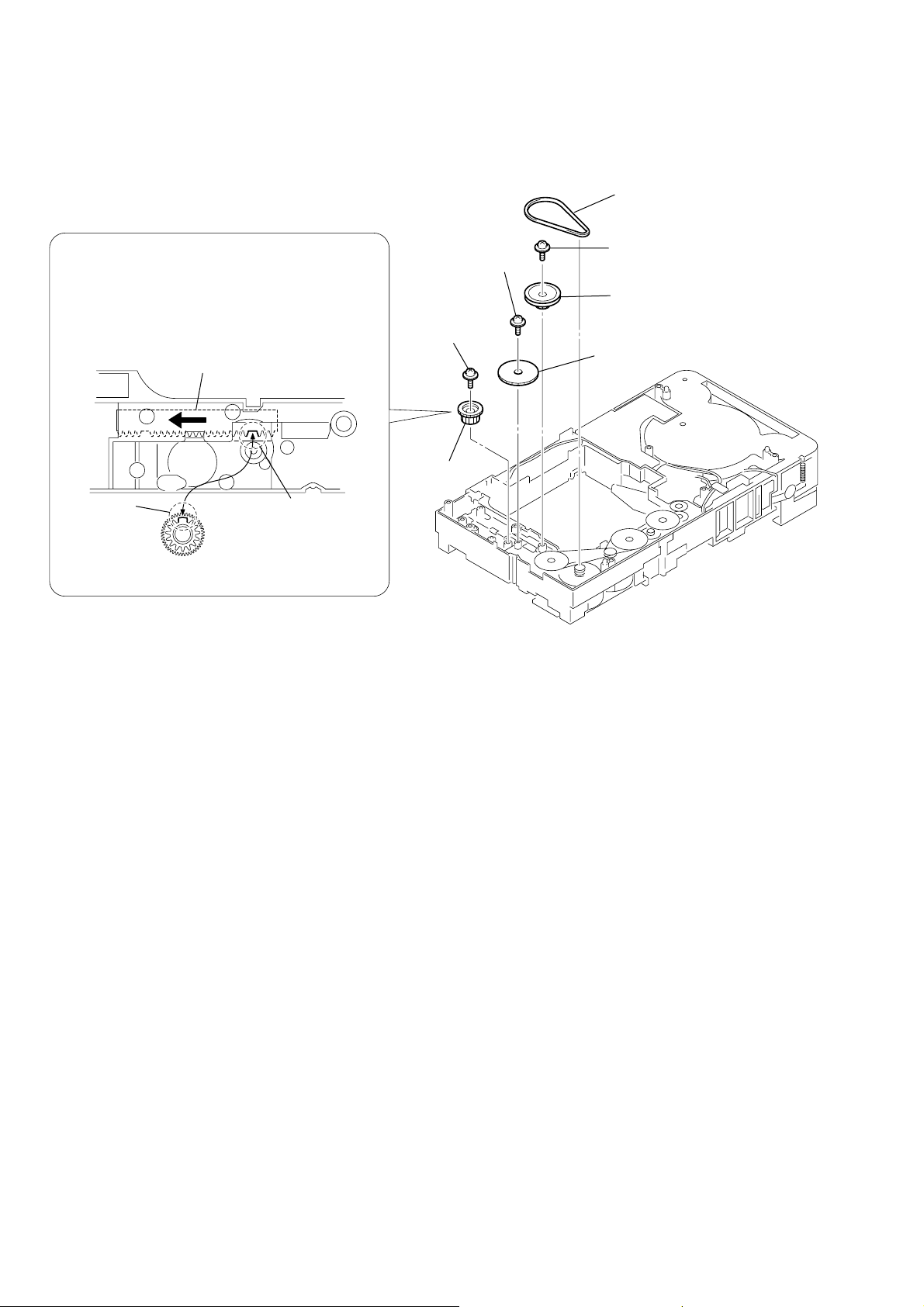
3-22. GEAR (BU1)
PRECAUTION DURING GEAR (BU2) INSTALLATION
4
Before re-assembling, slide the cam (BU) in the direction of
the arrow.
Assemble the gear (BU2) in such a manner that the groove
of the cam (BU) is aligned with the rib of the gear (BU2).
cam (BU)
screw
(PTPWH2.6
6
screw
(PTPWH2.6
7
gear (BU2)
×
8)
×
8)
1
belt (sub tray)
2
screw
(PTPWH2.6
3
pulley (BU)
5
gear (BU1)
×
8)
rib
groove
gear (BU2)
– CD mechanism deck bottom view –
22

HCD-HDX265/HDX266/HDX267W/HDX465/HDX466/HDX665
SECTION 4
TEST MODE
Note: Incorrect operations may be performed if the test mode is not entered
properly. In this case, press the I/1 button to turn the po wer off, and
retry to enter the test mode.
COLD RESET
The cold reset clears all data including preset data stored in the
RAM to initial conditions. Execute this mode when returning the
set to the customers.
Procedure:
1. Press the I/1 button to turn the power on.
2. Press three buttons x , A and I/1 simultaneously.
3. When this button is operated, display as “COLD RESET” for
a while and all of the settings are reset.
PANEL TEST MODE
This mode is used to check the software version, FL, LED and KEY.
2-1. Display Test Mode
Procedure:
1. Press the I/1 button to turn the power on.
2. Press three buttons X , . and A simultaneously.
3. When the display test mode is activated, all segments are turned on.
4. To exit from this mode, press three buttons X , . and A
simultaneously.
2-2. V ersion T est Mode
Procedure:
1. When the display test mode is activated, press the . button
and “DC2” (HDX265)/“DC2−” (HDX266)/“DC2W”
(HDX267W)/“DC4+” (HDX465/HDX466)/“DC7”
(HDX665) is displayed, the version test mode is acti v ated.
2. Whenever the . button is pressed, the display changes in
order of “DC2” (model name) t “NA” (destination) t MC
t SYS t UI t DVD t CDMA t CDMB t ST t TA t
DSP t TM t CLA t CEC t “DC2” (model name).
Note: Model name/destination is different according to model.
3. Press the > button and the date of the software production
is displayed.
4. Press the > button again and the version is displayed.
5. To exit from this mode, press three buttons X , . and A
simultaneously.
2-3. Key Test Mode
Procedure:
1. When the display test mode is activated, press the
to select the key test mode.
2. T o enter the KEY test mode, the fluorescent indicator displays
“K0 V0”. Each time an another button is pressed, “KEY” v alue
increases. However, once a button is pressed, it is no longer
taken into account. When all keys are pressed correctly, “K13
V0” is displayed.
3. When the [VOLUME] dial is turned in the direction of (+), “V0”
is changed to “V1”, then ... “V9”.
When the [VOLUME] dial is turned in the direction of ( −), “V0”
is changed to “V9”, then ... “V1”.
4. To exit from this mode, press three buttons X , . and A
simultaneously.
H button,
Releasing Procedure :
1. Press the x button and the A button simultaneously for five
seconds again.
2. The message “UNLOCKED” is displayed and the tray is
unlocked.
Note: When “LOCKED” is displayed, the tray lock is not released by
turning power on/off with the I/1 button.
DVD SHIP MODE
Use this mode when returning the set to the customer after repair.
Procedure:
1. Press the I/1 button to turn the set on.
2. Press the [FUNCTION] button to set the function “DVD”.
3. Remove all discs, and then press two buttons H and I/1
simultaneously.
4. After a message “MECHA LOCK” is displayed on the
fluorescent indicator tube, pull out the AC plug.
5. To exit from this mode, press the I/1 button to turn the set on.
AM STEP CHANGE
A step of AM channels can be changed o ver between 9 kHz and 10
kHz.
Procedure:
1. Press the I/1 button to turn the set ON.
2. Press the [FUNCTION] button to set the function “TUNER
AM”.
3. Press the I/1 button to turn the set OFF.
4. Press two buttons > and I/1 simultaneously, and the display
of fluorescent indicator tube changes to “ AM 9k STEP” or “ AM
10k STEP”, and thus the channel step is changed over.
PRODUCT OUT
This mode moves the optical pick-up to the position durable to
vibration and clears all data including preset data stored in the RAM
to initial conditions. Use this mode when returning the set to the
customer after repair.
Procedure:
1. Press the I/1 button to turn the power on.
2. Press the [FUNCTION] button to set the function “DVD”.
3. Remove all discs, and then press three buttons > , A and I/1
simultaneously.
4. After the “ST ANDBY” blinking display finishes, the message
“MECHA LOCK” is displayed on the fluorescent indicator
tube disconnect the A C po wer plug, then the ship mode is set.
AUTOMATIC ACOUSTIC FIELD CALIBRATION
MICROPHONE TEST MODE
Procedure:
1. Press the I/1 button to turn the power on.
2. Press the [FUNCTION] button to set the function other than
“DVD”.
3. Insert ECM-AC2 supplied as an accessory into the AUDIO
IN/A.CAL MIC jack.
4. While pressing the X and A buttons simultaneously, turn the
[VOLUME] dial in the direction of (+).
DISC TRAY LOCK
The disc tray lock function for the antitheft of an demonstration
disc in the store is equipped.
Setting Procedure :
1. Press the I/1 button to turn the set on.
2. Press the [FUNCTION] button to set DVD function.
3. Insert a disc.
4. Press the x button and the A button simultaneously for five
seconds.
5. The message “LOCKED” is displayed and the tray is locked.
23

HCD-HDX265/HDX266/HDX267W/HDX465/HDX466/HDX665
Ver. 1.1
5. Confirm that the following are shown on the display panel.
1 The JACK inserted/non-inserted detection display and the
STEREO/MONO detection display.
2 Presence of DIGITAL voice input to the microcomputer.
(OK: input, NG: no input)
3 The value of the MIC input to the microcomputer. (shown
“255h”)
* * * * * * * *
123
1 “NON”: Not detected
“ST” : STEREO
“MIN” : MONO
2 OK : input
NG : no input
3 0-255 (Changes in real time)
DEMO PLAY OUT
It is a mode to release the demonstration reproduct by the dedicated
demonstration disc.
Procedure:
1. During playback the DEMO disc, press the x and H buttons
for five seconds simultaneously.
2. The message “DEMO OFF” is displayed, a mode to reproduct
the demonstration is released.
VOLUME TEST MODE
Procedure:
1. Press the I/1 button to turn the power on.
2. Press three buttons
. , H and > simultaneously.
3. The message “VOLUME MAX” is displayed, when the
[VOLUME] dial is turned in the dirction of (+). The message
“VOLUME MIN” is displayed, when the [VOLUME] dial is
turned in the dirction of (−).
4. To exit from this mode, press the I/1 button to turn the set
off.
DVD COLOR SYSTEM SWITCHING (HDX265: E,
Australian models only)
This mode let you change the color system of the video output from
PAL to NTSC or vice-versa.
Procedure:
1. Press the I/1 button to turn the power on.
2. Press the [FUNCTION] button to select the “DVD”.
3. Press the I/1 button to turn the power off.
4. Press two buttons of X and I/1 simultaneously, and the set
will power on automatically.
5. DVD color system is switched.
During the protection state:
1. If the AC plug is connected or disconnected during the
protection state, the protection state is released, and the normal
operation is established. (The protection state is not
maintained.)
2. The protection factor is displayed by pressing the [FUNCTION] ,
A and > buttons at the same time during the protection state.
(during the “PROTECTOR” h “PUSH POWER” display)
When SD is detected: Repeats
“SD DETECT” h “PUSH POWER”.
When DC is detected: Repeats
“DC DETECT” h “PUSH POWER”.
SD detection:
When the “L” output from the SD (shutdown) port on the SMASTER POWER Driver is detected, the power system other
than that of the florescent indicator tube is turned off, and the
protection state is established.
DC detection:
When the “L” output from the power/speaker error detection circuit
(DC detection port) is detected for two seconds continually, the
power system other than that of the florescent indicator tube is
turned off, and the protection state is established.
DIGITAL MEDIA PORT TEST
Procedure:
1. Connect the DMPORT CHECK JIG (Part No.: J-2501-309A) with the terminal DMPORT.
2. Press the I/1 button to turn the power on.
3. Confirm that both LEDs of the DMPORT confirmation JIG
lights. (Confirmation the power supply line.)
4. Set the [FUNCTION] button with “DMPORT” on this model.
5. Press the X , . buttons and turn the [VOLUME] dial in the
direction of (+) simultaneously, the DMPORT test mode is
activated.
6. It is confirmed that “DMPORT OK” is displayed on this set
display. (Confirmation of communication line)
7. To a pinjack of the DMPORT confirmation JIG input
information relevant to audio signal (sine-wa ve 1.0Vrms) and
composite video signal (white 100% 1.0Vp-p, color bar, etc.)
8. Confirm the output of speakers and monitor TV. (Confirmation
of analog signal)
9. To e xit from this mode, press the X , . buttons and turn the
[VOLUME] dial in the direction of (+).
set
IO board
J301
TV
monitor
color pattern
generator
J001
DMPORT board
CN204
DMPORT
check jig
(Part No.:
J-2501-309-A)
PROTECTION FACTOR (SD DETECTION/DC DETECTION) IDENTIFICATION TEST MODE
When an error is detected, the florescent indicator tube alternately
displays “PROTECTOR” h “PUSH POWER”.
Press the I/1 button.
r
* Buttons other than the I/1 button are invalid.
“STANDBY” blinks three times on the florescent indicator tube.
r
The protection release state (POWER OFF) is established.
(No florescent indicator tube display)
Press the I/1 button.
r
The power to the system turns on, and the normal operation is
established. (Restore)
24
AF oscillator
SPEAKER board
TB780
FL/FR
speaker

HCD-HDX265/HDX266/HDX267W/HDX465/HDX466/HDX665
DVD SECTION
1. DVD SER VICE MODE GENERAL DESCRIPTION
This mode let you make diagnosis and adjustment easily by using
the remote commander and the TV screen. The instructions,
diagnostic results, etc. are given on the on-screen display.
Be sure to execute the IOP measurement when a base unit is replaced.
2. ENTERING DVD SERVICE MODE
Procedure:
1. Press the I/1 button to turn on the system.
2. Press the [FUNCTION] button repeatedly to select the “D VD”.
3. While pressing the x and A buttons simultaneously, turn
[VOLUME] dial in the direction of (+) with the D VD player in
power on .
4. The message “SERVICE IN” appears on the fluorescent
indicator tube and top menu of the Remocon Diagnosis Menu
appears on the on-screen display on the TV screen as follows.
The model name, IF-con version and Syscon version are
displayed at the bottom of the on-screen display.
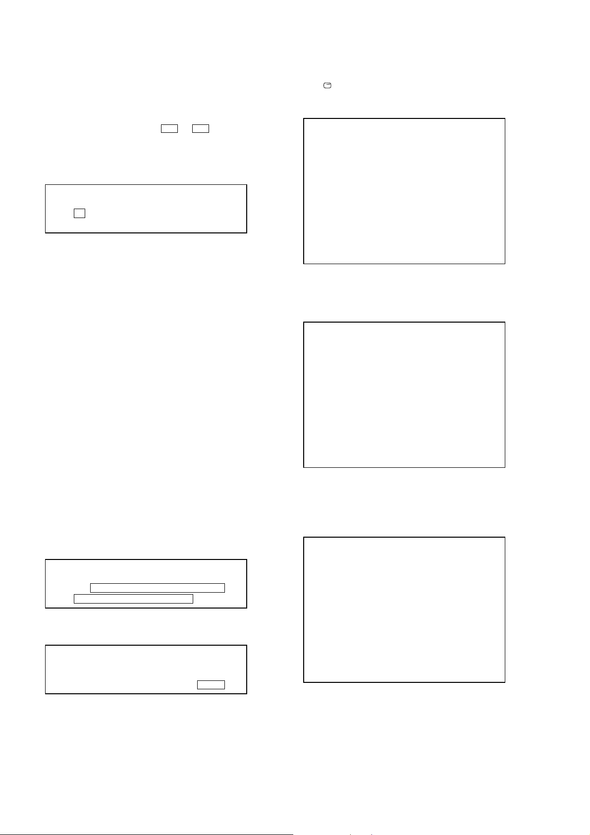
Remocon Diagnosis Menu
0. External Chip Check
1. Servo Parameter Check
2. Drive Manual Operation
3. Emergency History
4. Version Information
Model Name :xxxx_xx
IF-con:Ver.xx.xx(xxxx)
Syscon:Ver.x.xxx
5. To execute each function, press its number by using numeric
button on the remote commander.
6. T o release from this mode, press the I/1 button to turn off the
system.
3. EXECUTING IOP MEASUREMENT
In order to execute IOP measurement, the following standard
procedures must be followed.
Procedure:
1. From the top menu of Remocon Diagnosis Menu, select “2
Drive Manual Operation” by pressing the [2] button on the
remote commander. The following screen appears on the onscreen display
Drive Manual Operation
1. Servo Control
2. Track/Layer Jump
3. Manual Adjustment
4. Mecha test mode
5. MIRR time Adjust
0. Return to Top Menu
Manual Adjust
1. Track Balance Adjust:
2. Track Gain Adjust:
3. Focus Balance Adjust:
4. Focus Gain Adjust:
5. Eq boost Adjust:
6. Iop:
7. TRV. Level:
8. S curve(FE) Level:
9. RFL(PI) Level:
0. MIRR Time:
V v Change Value
[RETURN]Return to previous menu
3. Select “6. Iop:” by pressing [6] button on the remote
commander.
4. Wait until a hexadecimal number appear in the on-screen
display as below.
Manual Adjust
1. Track Balance Adjust:
2. Track Gain Adjust:
3. Focus Balance Adjust:
4. Focus Gain Adjust:
5. Eq boost Adjust:
6. Iop: ED:
7. TRV. Level:
8. S curve(FE) Level:
9. RFL(PI) Level:
0. MIRR Time:
V v Change Value
[RETURN]Return to previous menu
5. Convert data from he xadecimal to decimal by using conversion
table.
6. If the value is smaller than 93 (decimal), then it is OK. Howe ver
if the value is higher than 93, then BU (base unit) is defectiv e
and need to be change.
7. Press the O RETURN button on the remote commander to
return to previous menu.
8. Press the [0] button on the remote commander to return to the
top menu of Remocon Diagnosis Menu.
9. Press the I/1 button to turn off the system.
4. CHECKING EMERGENCY HISTORY
To check the emergency history, please follow the following
procedure.
Procedure:
1. From the top menu of Remocon Diagnosis Menu, select “3.
Emergency History” by pressing the [3] button on the remote
commander. The following screen appears on the on-screen
display.
Emg. History Check
Laser Hours CD 999h 59min
DVD 999h 59min
01. 01 05 04 04 00 92 46 00
00 00 00 00 00 00 23 45
2. Select “3. Manual Adjustment” by pressing the [3] button on
the remote commander. The following screen appears on the
on-screen display.
02. 02 02 01 01 00 A9 4B 00
00 00 00 00 00 00 23 45
[Next]Next page [Prev]Prev page
[0]Return to Top Menu
25
HCD-HDX265/HDX266/HDX267W/HDX465/HDX466/HDX665
2. Y ou can check the total time when the laser is turned on during
playback of DVD and CD from the above menu. The maximum
time, which can be displayed are 999h 59min.
3. You can check the error code of latest 10 emergency history
from the above menu. To view the previous or next page of
emergency history, press the . or > button on the
remote commander. The error code consists of three kinds of
error codes.
A. Error code
Example of Error code
01. 01 05 04 04 00 92 46 00
00 00 00 00 00 00 23 45
The meaning of error code is as below:
01: Communication error (No reply from syscon)
02: Syscon hung up
03: Power OFF request when syscon hung up
19: Thermal shutdown
24: MoveSledHome error
25: Mechanical move error (5 changer)
26: Mechanical move stack error
30: DC motor adjustment error
31: DPD offset adjustment error
32: TE balance adjustment error
33. TE sensor adjustment error
34. TE loop gain adjustment error
35. FE loop gain adjustment error
36. Bad jitter after adjustment
40. Focus NG
42. Focus layer jump NG
51: Spindle stop error
52. Open kick spindle error
60: Focus on error
61: Seek fail error
62: Read Q data/ID error
70: Lead in data read fail
71: TOC read time out (CD)
80: Can’t buffering
81: Unknown media type
B. Parameter of error code
This is the detail of error code.
Example of Error code
To Clear the Laser Hour
Press the [ DISPLAY] button on the remote commander and then
press the [CLEAR] button on the remote commander. The data for
both CD and DVD data are reset.
Emg. History Check
Laser Hours CD 0h 0min
DVD 0h 0min
01. 01 05 04 04 00 92 46 00
00 00 00 00 00 00 23 45
02. 02 02 01 01 00 A9 4B 00
00 00 00 00 00 00 23 45
[Next]Next page [Prev]Prev page
[0]Return to Top Menu
To Clear the Emergency History
Press the [DVD TOP MENU] button on the remote commander and
then press the [CLEAR] button on the remote commander. The error
code for all emergency history would be reset.
Emg. History Check
Laser Hours CD 999h 59min
DVD 999h 59min
01. 00 00 00 00 00 00 00 00
00 00 00 00 00 00 00 00
02. 00 00 00 00 00 00 00 00
00 00 00 00 00 00 00 00
[Next]Next page [Prev]Prev page
[0]Return to Top Menu
To Execute the Initialize Setup Data
Procedure:
1. Press the [DVD MENU] button on the remote commander and
then press the [CLEAR] button on the remote commander. The
following screen appears on the on-screen display.
Emg. History Check
Laser Hours CD 999h 59min
DVD 999h 59min
01. 01 05 04 04 00 92 46 00
00 00 00 00 00 00 23 45
C. Time of error code
This is the laser time when an error occurred.
Example of Error code
01. 01 05 04 04 00 92 46 00
00 00 00 00 00 00 23 45
26
Initialize setup data...
[Next]Next page [Prev]Prev page
[0]Return to Top Menu
2. The screen after a while returns to former display.
To Return to the Top Menu of Remocon Diagnosis
Menu
Press the [0] button on the remote commander.

HCD-HDX265/HDX266/HDX267W/HDX465/HDX466/HDX665
5. CHECKING VERSION INFORMATION
To check the version information, please follow the following
procedure.
Procedure:
1. From the top menu of Remocon Diagnosis Menu, select “4.
Version Information” by pressing the [4] button on the remote
commander. The following screen appears on the on-screen
display.
Version information
Firm(Main): Ver. X.XXXX
Firm(Sub): XX.XX
RISC: XXXXXX
8032: XXXXXX
Audio DSP: XX.XX.XX.XX
Servo DSP: XX.XX.XX.XX
[0]Return to Top Menu
2. T o return to the top menu of Remocon Diagnosis Menu, press
the [0] on the remote commander.
27

HCD-HDX265/HDX266/HDX267W/HDX465/HDX466/HDX665
signal
generator
set
SECTION 5
ELECTRICAL ADJUSTMENTS
DVD SECTION
When the base unit is replaced, perform the adjustment and the
measurement as shown below in this order.
EXECUTING IOP MEASUREMENT (See page 25)
TUNER SECTION
FM TUNE LEVEL CHECK
Procedure:
1. Turn on the set.
2. Input the following signal from signal generator to FM antenna
input directly.
Carrier frequency: A = 87.5 MHz, B = 98 MHz, C = 108 MHz
Deviation : 75 kHz
Modulation : 1 kHz
ANT input : 35 dBu (EMF)
Note: Use 75 ohm coaxial cable to connect signal generator and the set.
You cannot use video cable for checking.
Use signal generator whose output impedance is 75 ohm.
3. Set to FM tuner function and tune A, B and C signals.
4. Confirm “TUNED” is lit on the display for A, B and C signals.
When the selected station signal is received in good condition,
“TUNED” is displayed.
28

SECTION 6
DIAGRAMS
6-1. BLOCK DIAGRAM – RF SERVO/VIDEO Section –
OPTICAL PICK-UP
BLOCK
KHM-310CAB
OR
KHM-313CAB
VR (780)
VOA/A
VOB/B
VOC/C
VOD/D
MSW
RF
PD
AUTOMATIC POWER
CONTROL (FOR CD)
Q1102-1
AUTOMATIC POWER
CONTROL (FOR DVD)
Q1102-2
CD ON
SWITCH
Q1101-1
DVD ON
SWITCH
Q1101-2
Q1103
6
DVDRFIP
8
MA
MB
9
MC
10
MD
11
DVDA2
DVDB3
DVDC4
DVDD5
TNI18VOE/E+G
TPI19VOF/F+H
SMPTE_Y (0)
SMPTE_Y (1)
V2O29VC
SMPTE_Y (2)
MDI120
SMPTE_Y (3)
MDI221
SMPTE_Y (4)
SMPTE_Y (5)
LDO123LD (780)
SMPTE_Y (6)
SMPTE_Y (7)
22LD (650)
LDO2
RF AMP, SERVO DSP,
MPEG DECODER
IC1101
MSW
51VR (650)
LIMITSW
130LIMIT
SPDIF 216
ASDATA1 202
ASDATA2
ASDATA4 214
ABCK 210
ALRCK 209
ACLK 211
VCLK
HDMI_SDA
HDMI_SCL
PWON
ADIN
CVBS
HCD-HDX265/HDX266/HDX267W/HDX465/HDX466/HDX665
C OUT
Y OUT
AMP BUS
HDMI BUS
23
26
27
21
AUDIO SELECTOR
IC3003
1
A
5
Y
2
B
A/B
6
203
BUFFER
ACLK
IC4501
A/D CONVERTER
IC772
9
DOUT
BCK
LRCK
SCKI
VinL
VinR
(Page 30)
8
7
6
13
14
R-CH
L-CH
D
(Page 31)
197ASDATA0
ASDATA0
ABCK
ALRCK
SPDIF
165
164
163
162
161
159
158
157
166
104
103
223
212
187
YUV0
YUV1
YUV2
YUV3
YUV4
YUV5
YUV6
YUV7
VCLK
HDMI_SDA
HDMI_SCL
PWON
(Page 30)
D2
D3
D1
BCK
LRCK
MCK
V_SEL2
F
DMPORT_VIDEO
G
VIDEO AMP, 75 ohm DRIVER
4
IC302
CVBS OUT
S-DC OUT
CVBSin
(Page 32)
B
C
(Page 30)
1
SW
4
IN2
OUT
6
IN1
VIDEO SELECTOR
IC301
2
CY
VIDEO
S VIDEO
(DVD ONLY)
J301
MONITOR
OUT
FOCUS/TRACKING COIL DRIVE,
SPINDLE/SLED MOTOR DRIVE
IC1201
A
(Page 30)
FCS+
FCS– 37
TRK+ 35
TRK– 34
SL+ 29
SL– 30
SP+ 27
SP– 28
REGO2
REGO1
TX27M
SDA
SCL
36
46
47
41
31
32
FOCUS
COIL DRIVE
TRACKING
COIL DRIVE
SLED
MOTOR DRIVE
SPINDLE
MOTOR DRIVE
BUFFER
BUFFER
REGULATOR
MUTE5
1
4
10
13
45
19
21
20
22
40
RF+3.3V
8
HCD-HDX265/HDX266/HDX267W/HDX465/HDX466/HDX665
112
34
WIDE
108
38
MTK RST XSYSRST
DVD_XIFBUSY IFBSY
2
Cin
6
Yin
10
CYin
12
Cb in
14
Cr in
S1
25
177
82
SYSTEM CONTROLLER
IC501 (1/5)
CY OUT
Cb OUT
Cr OUT
MUTE113MUTE2
3
83
V_SEL1
V_SEL0
20
18
16
PB/C
PR/C
Y
B
R
J302
COMPONENT
VIDEO OUT
(DVD ONLY)
• R-CH is omitted due to same as L-CH.
• SIGNAL PATH
: CD/DVD PLAY
: AUDIO
: VIDEO
XRST
E
(Page 30)
189
C
191
Y
185
Y/G
FOO42
TRO41
FMO38
DMO37
SPFG50
MUTE123MUTE12 171
MUTEMUTE34 169
TSD_MTSD-M 168
IOPMON40
B/Cb/Pb
R/Cr/Pr
XTALI
234
183
182
OSC
BUFFER
IC1111
DQ0 – DQ15
2, 4, 5, 7, 8, 10, 11, 13, 42,
44, 45, 47, 48, 50, 51, 53
121 – 119, 117 – 113,
129 – 122
RD0 – RD15
X1101
27MHz
SDASDA
102
101
5
EEPROM
IC1103
SCLSCL
EEWPWE
54
6
7
SD-RAM
IC1104
A0 – A11
23 – 26,
29 – 34, 22, 35
140, 141, 143, 144,
155 – 150, 139, 149
RA0 – RA11
HD0 – HD7
79, 80,
82 – 86, 89
29, 31, 33, 35,
38, 40, 42, 44
DQ0 – DQ7
20
21
38
37
15
137
138
146
147
111
BA0 BA0
BA1 BA1
CKE CLKE
DRCLK CLK
HA0 – HA21
92, 77, 56 – 62, 74 – 67,
91, 63, 64, 75, 87
45, 25 – 18, 8 – 1,
48, 17, 16, 9, 10
A-1, A0 – A20
FLASH ROM
IC1102
39
132
DQM0 LDQM
18
135
DQM1 UDQM
17
134
RAS /RAS
76
26
19
136
CAS /CAS
XROMCSCE
78
28
RCS /CS
XRDOE
16
133
RWE /WE
XWRWE
66
11
12
RESET
79
M_ST
97
100
99
98
32
37
31
33
DVD_SID IFSDI
DVD_SCO IFSCK
DVD_SOD IFSDO
DVD XIFCS xIFCS
2929

HCD-HDX265/HDX266/HDX267W/HDX465/HDX466/HDX665
6-2. BLOCK DIAGRAM – CHANGER/HDMI/DMPORT Section –
CHANGER CONTROL
P0FIN
247
P1RIN 23
IC621
M761
(LD/ST MOTOR)
LD/ST MOTOR DRIVER
IC701
4
M
OUT1
OUT2
2 9
CHANGER CONTROL,
AUDIO/VIDEO CONTROL
IC622
P3
• R-CH is omitted due to same as L-CH.
HDMI TRANSMITTER
IC1701
(Page 29)
21
VSEL_2
F
(Page 29)
TX27M
SDA
A
SCL
CLK26
SSO22
SSCK21
• SIGNAL PATH
: AUDIO
: VIDEO
M762
(BU U/D MOTOR)
S761 (SUB TRAY OUT)
S731 (SUB TRAY IN)
S721 (MAIN TRAY IN/OUT)
M
IN
OPEN
D SENSOR
IC751
BU U/D MOTOR DRIVER
IC711
OUT1
4
OUT2
2 9
DISC SENSOR
Q751
CDM_OPEN_SW
27
IO_DI
IO_CLK
IO_CE
IO_RESET
IO-DO
CEC_TX_OUT
CEC_RX_IN
CLINK_TX_OUT
CLINK_RX_IN
CLINK_DET
SYSTEM CONTROLLER
IC501 (2/5)
86
88 CLK3
84 LATCH4
85
87
22
3
30
29
89
12
9
10
2
P4FIN 207
P5RIN 19
P8
P11
P10
P911
DI126
RESET_B
DO2
DO1
CLKO
LATCHO
17
P7
18
P6
5 – 8
P15 – P12
9 – 12
P11 – P8
25
15
14
13
26
LINE AMP
IC202
DI216
DI1
CLK3
LATCH4
RESET_B2
DO2
CN204
DMPORT
6
5
7
13
14
17
25
TXD
RXD
DET
Lch
RchR-CH
VIDEO
A_SEL0
A_SEL1
ROTARY
ENCODER
S771
(MD)
ROTARY
ENCODER
S781
(ST U/D)
H
(Page 31)
(Page 29)
C
HDMI BUS
ASDATA0
SPDIF
ACLK
ABCK
ALRCK
YUV0
YUV1
YUV2
YUV3
YUV4
YUV5
YUV6
YUV7
VCLK
PWON
HDMI_SDA
HDMI_SCL
72
78
79
13
14
15
16
17
18
19
20
24
AD373
SPDIF
ACK77
ABCK
ALRCK
Y0
Y1
Y2
Y3
Y4
Y5
Y6
Y7
VCK11
#PWON
TCKN
HTPLG 40
RST
25
CN1701
HDMI OUT
(DVD ONLY)
7
52TX0P
51TX0N
55TX1P
54TX1N
58TX2P
57TX2N
49TCKP
48
LEVEL SHIFT
IC1705
LEVEL SHIFT
Q1701
CEC DATA
SWITCH
Q9724, 9726,
Q9728, 9729
+5V
SW+9V
REGULATOR
IC1707
TMDS DATA0 +
9
TMDS DATA0 –
4
TMDS DATA1 +
6
TMDS DATA1 –
1
TMDS DATA2 +
3
TMDS DATA2 –
10
TMDS CLOCK +
12
TMDS CLOCK –
19
HPD
16
SDA
15
SCL
13
CEC
18
+5V POWER
XRST
E
(Page 29)
(Page 31)
(Page 29)
DMPORT_L
J
DMPORT_VIDEO
G
HCD-HDX265/HDX266/HDX267W/HDX465/HDX466/HDX665
3030
 Loading...