

Sony HCDGX-9000 Service manual
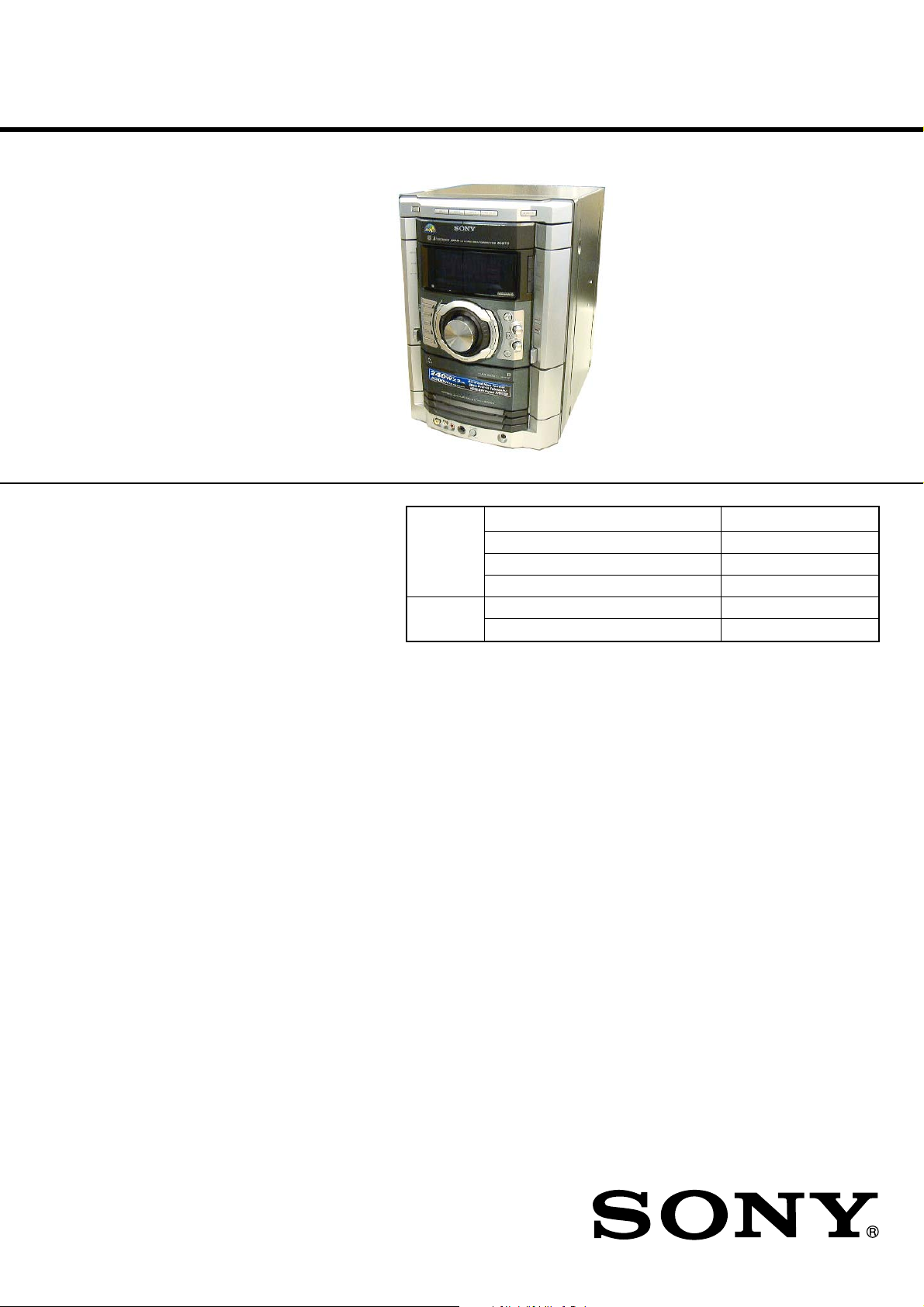
HCD-GN660/GN770/
GX9000
SERVICE MANUAL
Ver. 1.1 2006. 02
• HCD-GN660/GN770/GX9000 are the
Amplifier, CD player, tape deck and tuner
section in MHC-GN660/GN770/GX9000.
Photo : GN770
Model Name Using Similar Mechanism HCD-GX450
CD CD Mechanism Type CDM74-F1BD81
Section Base Unit Name BU-F1BD81A
Optical Pick-up Name KSM-215DCP/C2NP
TAPE Model Name Using Similar Mechanism NEW
Section Tape Transport Mechanism Type CWM43RR35
US Model
HCD-GX9000
E Model
HCD-GN660/GN770
Australian Model
HCD-GN770
SPECIFICATIONS
AUDIO POWER SPECIFICATION
(MHC-GX9000 USA model only)
POWER OUTPUT AND TOTAL HARMONIC
DISTORTION:
With 6-ohm loads, both channels driven, from 120 Hz – 10 kHz;
rates 225 watts per channel minimum RMS power, with no more
than 10% total harmonic distortion from 250 miliwatts to rated
output.
Amplifier section
MHC-GX9000
Total harmonic distortion Less than 0.1%
(6 ohms at 1 kHz, 100 W)
MHC-GN770
The following are measured at
Mexican model: AC 127 V, 60 Hz
Other models: AC 120, 220, 240 V, 50/60 Hz
DIN power output (rated) 170 + 170 watts
(6 ohms at 1 kHz, DIN)
Continuous RMS power output (reference)
220 + 220 watts
(6 ohms at 1 kHz, 10% THD)
MHC-GN660
The following are measured at
Mexican model: AC 127 V, 60 Hz
Other models: AC 120, 220, 240 V, 50/60 Hz
DIN power output (rated) 150 + 150 watts
(6 ohms at 1 kHz, DIN)
Continuous RMS power output (reference)
190 + 190 watts
(6 ohms at 1 kHz, 10% THD)
Inputs
VIDEO/MD (AUDIO) IN (phono jacks):
voltage 250/450 mV, impedance 47
kiloohms
GAME (VIDEO) IN (phono jack):
1 Vp-p, 75 ohms
GAME (AUDIO) IN (phono jack):
voltage 250 mV, impedance 47 kiloohms
MIC (phone jack):
Outputs
VIDEO OUT (phono jack): max. output level
PHONES (stereo mini jack):
sensitivity 1 mV, impedance 10 kiloohms
1 Vp-p, unbalanced, Sync negative,
load impedance 75 ohms
accepts headphones of 8 ohms or more
– Continued on next page –
MiNi Hi-Fi COMPONENT SYSTEM
9-877-800-02
2006B02-1
© 2006.02
Sony Corporation
Home Audio Division
Published by Sony Techno Create Corporation
HCD-GN660/GN770/GX9000
FRONT SPEAKER: Use only the supplied speaker
SS-GN880
SURROUND SPEAKER: Use only the supplied
(MHC-GN770/ GX9000 only)
speaker SS-RS880
Disc player section
System
Compact disc and digital audio system
Laser Semiconductor laser
(λ=780 nm)
Emission duration: continuous
Laser Output Max. 44.6 µW*
*This output is the value measured
at a distance of 200 mm from the
objective lens surface on the Optical
Pick-up Block with 7 mm aperture.
Frequency response 2 Hz – 20 kHz (±0.5 dB)
Wave length 780 – 790 nm
Signal-to-noise ratio More than 90 dB
Dynamic range More than 90 dB
OPTICAL CD DIGITAL OUT
(MHC-GN770/GN660 only)
(Square optical connector jack, rear panel)
Wave length 660 nm
Output Level –18 dBm
Tape deck section
Recording system 4-track 2-channel stereo
Frequency response 50 – 13,000 Hz (±3 dB), using Sony
TYPE I tape
Tuner section
FM stereo, FM/AM superheterodyne tuner
FM tuner section
Tuning range 87.5 – 108.0 MHz
Antenna FM lead antenna
Antenna terminals 75 ohm unbalanced
Intermediate frequency 10.7 MHz
AM tuner section
Tuning range
North and Latin American models:
530 – 1,710 kHz
(with the interval set at 10 kHz)
531 – 1,710 kHz
(with the interval set at 9 kHz)
Middle Eastern models: 531– 1,602 kHz (with the interval set
at 9 kHz)
Other models: 531 – 1,602 kHz (with the interval
set at 9 kHz)
530 – 1,710 kHz (with the interval
set at 10 kHz)
Antenna AM loop antenna
Antenna terminals External antenna terminal
Intermediate frequency 450 kHz
Dimensions (w/h/d) (Approx.)
HCD-GN770/GX9000/GN660
280 x 360 x 394.5 mm
Mass (Approx.)
HCD-GN770 12.4 kg
HCD-GX9000 12.0 kg
HCD-GN660 11.5 kg
Supplied accessories: Remote Commander (1)
Batteries (2)
AM loop antenna (1)
FM lead antenna (1)
Front speaker pads (8)
Surround speaker pads (8)
(MHC-GN770/GX9000 only)
Design and specifications are subject to change without notice.
SAFETY CHECK-OUT
After correcting the original service problem, perform the following
safety checks before releasing the set to the customer:
Check the antenna terminals, metal trim, “metallized” knobs, screws,
and all other exposed metal parts for AC leakage. Check leakage as
described below.
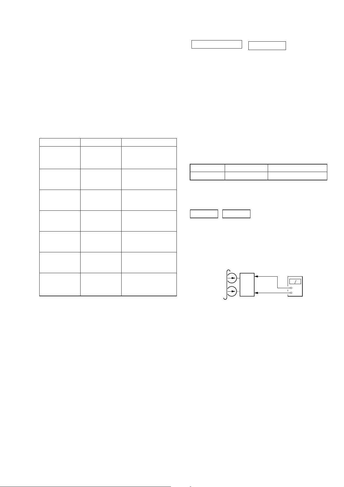
LEAKAGE
The AC leakage from any exposed metal part to earth ground and
from all exposed metal parts to any exposed metal part having a
return to chassis, must not exceed 0.5 mA (500 microamperes).
Leakage current can be measured by any one of three methods.
1. A commercial leakage tester , such as the Simpson 229 or RCA
WT -540A. Follow the manufacturers’ instructions to use these
instruments.
2. A battery-operated AC milliammeter . The Data Precision 245
digital multimeter is suitable for this job.
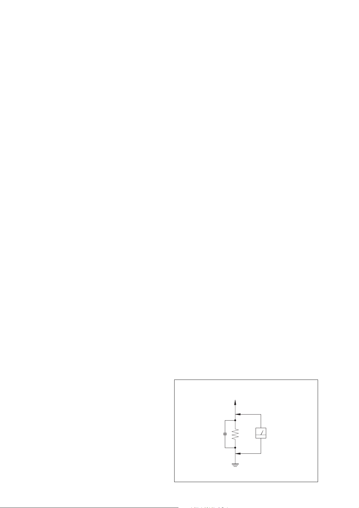
3. Measuring the voltage drop across a resistor by means of a
VOM or battery-operated AC voltmeter . The “limit” indication
is 0.75 V, so analog meters must have an accurate low-voltage
scale. The Simpson 250 and Sanwa SH-63Trd are examples
of a passive VOM that is suitable. Nearly all battery operated
digital multimeters that have a 2V AC range are suitable. (See
Fig. A)
General
Power requirements
North American models: 120 V AC, 60 Hz
Australian model: 230 – 240 V AC, 50/60 Hz
Mexican model: 127 V AC, 60 Hz
Argentina models: 220 V AC, 50/60 Hz
Other models: 120 V , 220 V or 230 – 240 V AC, 50/
60 Hz
Adjustable with voltage selector
Power consumption
MHC-GN770 215 watts
MHC-GX9000 235 watts
MHC-GN660 175 watts
2
To Exposed Metal
Parts on Set
AC
0.15 µF
Fig. A. Using an A C v oltmeter to check A C leakage.
1.5 kΩ
Earth Ground
Voltmeter
(0.75 V)

TABLE OF CONTENTS
HCD-GN660/GN770/GX9000
1. SERVICING NOTES ................................................ 4
2. GENERAL
Location of Controls........................................................ 5
3. DISASSEMBLY
3-1. Disassembly Flow ........................................................... 7
3-2. Case ................................................................................. 8
3-3. Loading Panel Assy ......................................................... 8
3-4. Front Panel Assy.............................................................. 9
3-5. CD Mechanism Deck (CDM74-F1BD81) ...................... 9
3-6. Tape Mechanism Deck, Game Board.............................. 10
3-7. CD Switch Board, Panel Board ....................................... 10
3-8. Switch Board ................................................................... 11
3-9. Tuner Pack ....................................................................... 11
3-10. Primary Board ................................................................. 12
3-11. Rear Panel........................................................................ 12
3-12. Main Board ...................................................................... 13
3-13. Surround Board, PA Board .............................................. 13
3-14. Power Transformer .......................................................... 14
3-15. Driver Board, SW Board ................................................. 14
3-16. BD Board, Optical Pick-Up (KSM-215DCP/C2NP) ...... 15
3-17. Sensor Board ................................................................... 15
3-18. Motor (TB) Board ........................................................... 16
3-19. Motor (LD) Board ........................................................... 16
4. TEST MODE .............................................................. 17
5. MECHANICAL ADJUSTMENTS ....................... 21
7. DIAGRAMS
7-1. Circuit Board Location .................................................... 26
7-2. Block Diagram – CD Section – ...................................... 28
7-3. Block Diagram – Tuner/Tape Deck Section – ................ 29
7-4. Block Diagram – Main Section – ................................... 30
7-5. Block Diagram – Display/Power Section – .................... 31
7-6. Printed Wiring Board – BD Board – .............................. 32
7-7. Schematic Diagram – BD Board – ................................. 33
7-8. Printed Wiring Board – CD Mechanism Board –........... 34
7-9. Schematic Diagram – CD Mechanism Board – ............. 35
7-10. Printed Wiring Boards – Main Board –.......................... 36
7-11. Schematic Diagram – Main Board (1/3) – ..................... 37
7-12. Schematic Diagram – Main Board (2/3) – ..................... 38
7-13. Schematic Diagram – Main Board (3/3) – ..................... 39
7-14. Printed Wiring Boards
– Game, CD Switch Board – ........................................... 40
7-15. Schematic Diagram
– Game, CD Switch Board – ........................................... 41
7-16. Printed Wiring Board – PA Board – ............................... 42
7-17. Schematic Diagram – PA Board – .................................. 43
7-18. Schematic Diagram –Panel Board (1/2) – ...................... 44
7-19. Schematic Diagram –Panel Board (2/2) – ...................... 45
7-20. Printed Wiring Board – Panel Board – ........................... 46
7-21. Printed Wiring Boards – Primary Board – ..................... 47
7-22. Schematic Diagram – Primary Board – .......................... 48
7-23. Schematic Diagram – Surround Board – ........................ 48
7-24. Printed Wiring Board – Surround Board – ..................... 49
7-25. IC Block Diagram ........................................................... 50
7-26. IC Pin Function Description ............................................ 51
6. ELECTRICAL ADJUSTMENTS
Deck section .................................................................... 21
CD Section ...................................................................... 22
Notes on chip component replacement
• Never reuse a disconnected chip component.
• Notice that the minus side of a tantalum capacitor may be
damaged by heat.
Flexible Circuit Board Repairing
• Keep the temperature of soldering iron around 270˚C
during repairing.
• Do not touch the soldering iron on the same conductor of the
circuit board (within 3 times).
• Be careful not to apply force on the conductor when soldering
or unsoldering.
CAUTION
Use of controls or adjustments or performance of procedures
other than those specified herein may result in hazardous
radiation exposure.
8. EXPLODED VIEWS
8-1. Case, Rear Panel Section ................................................. 57
8-2. Front Panel Section ......................................................... 58
8-3. Chassis Section ................................................................ 59
8-4. CD Mechanism Deck Section-1
(CDM74-F1BD81) .......................................................... 60
8-5. CD Mechanism Deck Section-2
(CDM74-F1BD81).......................................................... 61
9. ELECTRICAL PARTS LIST................................ 62
SAFETY-RELATED COMPONENT WARNING!!
This appliance is classified as
a CLASS 1 LASER product.
This label is located on the rear
exterior.
COMPONENTS IDENTIFIED BY MARK 0 OR DOTTED LINE WITH
MARK 0 ON THE SCHEMATIC DIAGRAMS AND IN THE PARTS
LIST ARE CRITICAL TO SAFE OPERATION. REPLACE THESE
COMPONENTS WITH SONY PARTS WHOSE PART NUMBERS
APPEAR AS SHOWN IN THIS MANUAL OR IN SUPPLEMENTS
PUBLISHED BY SONY .
3
HCD-GN660/GN770/GX9000
SECTION 1
SERVICING NOTES
NOTES ON HANDLING THE OPTICAL PICK-UP BLOCK
OR BASE UNIT
The laser diode in the optical pick-up block may suffer electrostatic
break-down because of the potential difference generated by the
charged electrostatic load, etc. on clothing and the human body.
During repair, pay attention to electrostatic break-down and also
use the procedure in the printed matter which is included in the
repair parts.
The flexible board is easily damaged and should be handled with
care.
NOTES ON LASER DIODE EMISSION CHECK
The laser beam on this model is concentrated so as to be focused on
the disc reflective surface by the objective lens in the optical pickup block. Therefore, when checking the laser diode emission, observe
from more than 30 cm away from the objective lens.
LASER DIODE AND FOCUS SEARCH OPERA TION CHECK
Carry out the “S curve check” in “CD section adjustment” and check
that the S curve waveform is output several times.
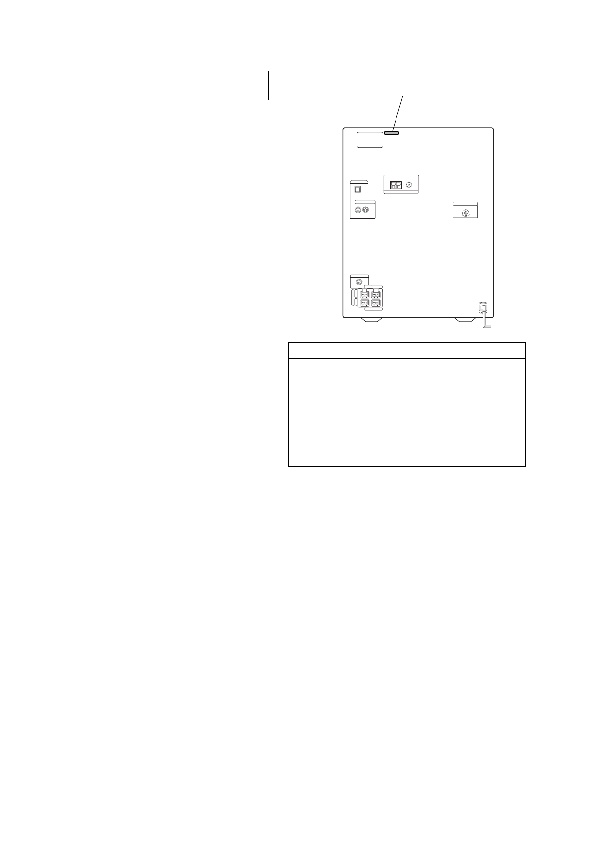
• MODEL IDENTIFICATION
– Back Panel –
MODEL PART No.
GN770: E2, E3models 4-252-722-0[]
GX9000 4-252-722-1[]
GN770: AUS model 4-252-722-2[]
GN770: E51 model 4-252-722-3[]
GN770: Mexican model 4-252-722-4[]
GN660: E2, E3models 4-252-555-0[]
GN770: E51 model 4-252-555-1[]
GN770: Mexican model 4-252-555-2[]
GN660: AR model 4-252-555-3[]
PART No.
•Abbreviation
E2 : 120 V AC Area in E model
E3 : 240 V AC Area in E model
E51 : Chilean and Peruvian model
AUS : Australian model
AR : Argentine model
4
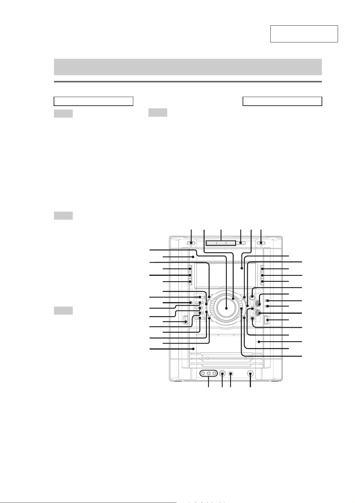
SECTION 2
Main unit
ALBUM qh
AMP MENU ek
CD eh
CD SYNC qf
Deck A wj
Deck B w;
DIRECTION qa
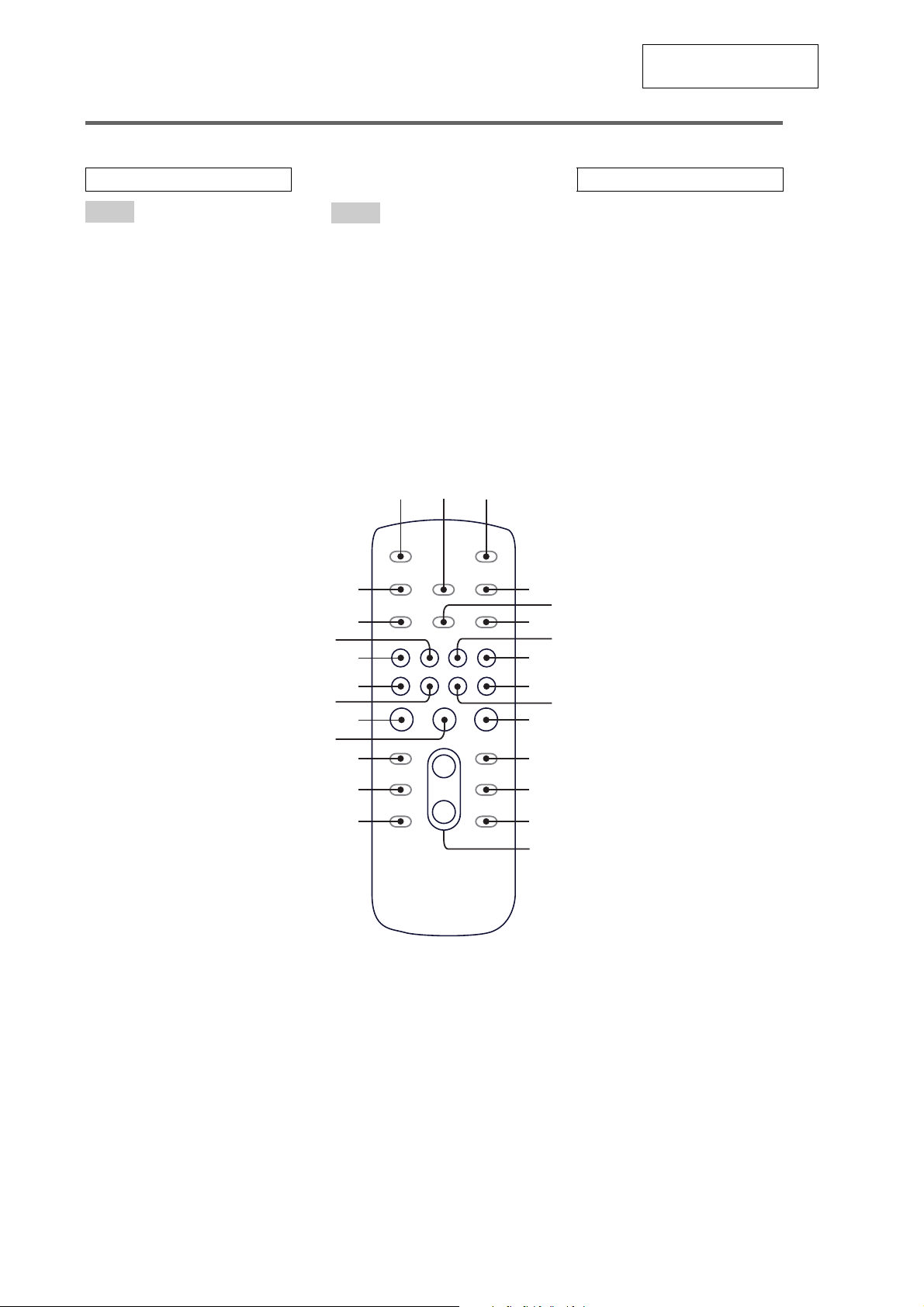
DISC 1 ~ 3 3
Disc tray rs
DISPLAY r;
Display 5
EFFECT ON/OFF ej
ENTER wa
EQ EDIT 8
EX-CHANGE/DISC SKIP 4
FM MODE q;
GAME e;
GAME INPUT (jacks) wh
GAME MIXING ef
GROOVE wl
ILLUMINATION wk
MIC (jack) wg
MIC LEVEL wf
MULTI JOG ws
P FILE MEMORY 7
PHONES (jack) wd
PLAY MODE 9
Power illuminator 2
REC PAUSE/START qg
REPEAT q;
SLEEP el
SURROUND (MHC-GN660
only)
ra
SURROUND SPEAKER MODE
(except for MHC-GN660 only)
ra
TAPE A/B ed
TUNER/BAND eg
TUNER MEMORY qa
TUNING MODE 9
VIDEO/MD es
VOLUME rd
?/1 (power) 1
Z OPEN/CLOSE 6
n N (play) qs
. > (go backward/forward)
qd
m M (rewind/fast forward)
qh
X (pause) ql
x (stop) qk
Z A (Eject A) ea
Z B (Eject B) qj
List of button locations and reference pages
ALPHABETICAL ORDER
A – D
E – L
M – R
S – Z
SYMBOLS
hH
A
A
wgwf wdwh
qh
qk
qg
qf
qj
w;
ws
ql
wa
9
qa
qd
q;
qs
7
8
2
eg
rs
r;
el
ra
rd
eh
ek
ej
ef
ea
wj
ed
es
e;
wl
wk
GENERAL
LOCA TING THE CONTROLS
HCD-GN660/GN770/GX9000
This section is extracted
from instruction manual.
41 3 65
5
HCD-GN660/GN770/GX9000
Remote c ontrol
This section is extracted
from instruction manual.
ALPHABETICAL ORDER
A – E
ALBUM + qf
ALBUM – qh
CD wf
CLEAR qk
CLOCK/TIMER SELECT 2
CLOCK/TIMER SET 4
DISC SKIP qd
DISPLAY wh
ENTER qs
EQ qj
F – Z
FM MODE 6
FUNCTION 8
PLAY MODE 5
REPEAT 6
SLEEP 1
TAPE wd
TUNER/BAND 7
TUNER MEMORY wg
TUNING MODE 5
VOLUME +/– qg
12
wh
wg
wf
wd
SYMBOLS
?/1 (power) 3
x (stop) qa
X (pause) ql
N (play) w;
–. (go backward) ws
>+ (go forward) wa
m (rewind) q;
M (fast forward) 9
3
4
5
6
7
8
wa
ql
ws
w;
qk
qj
qh
9
q;
qa
qs
qd
qf
qg
6
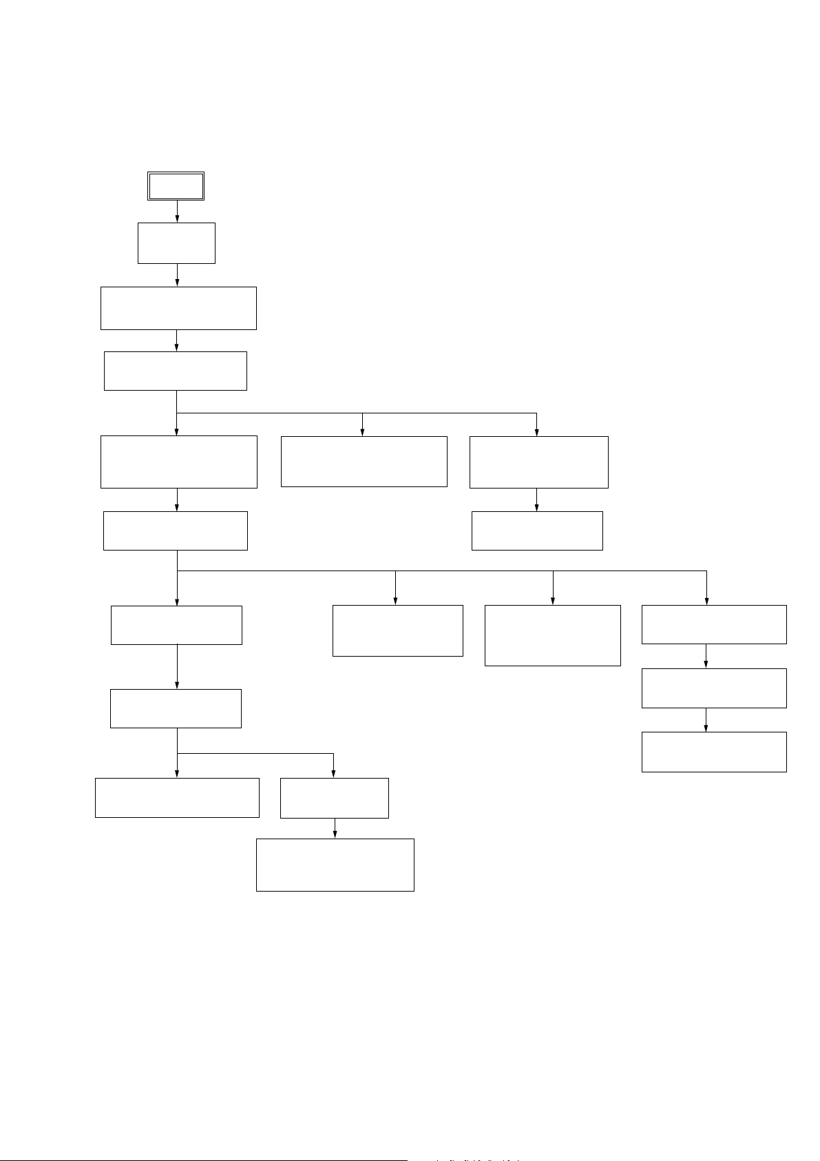
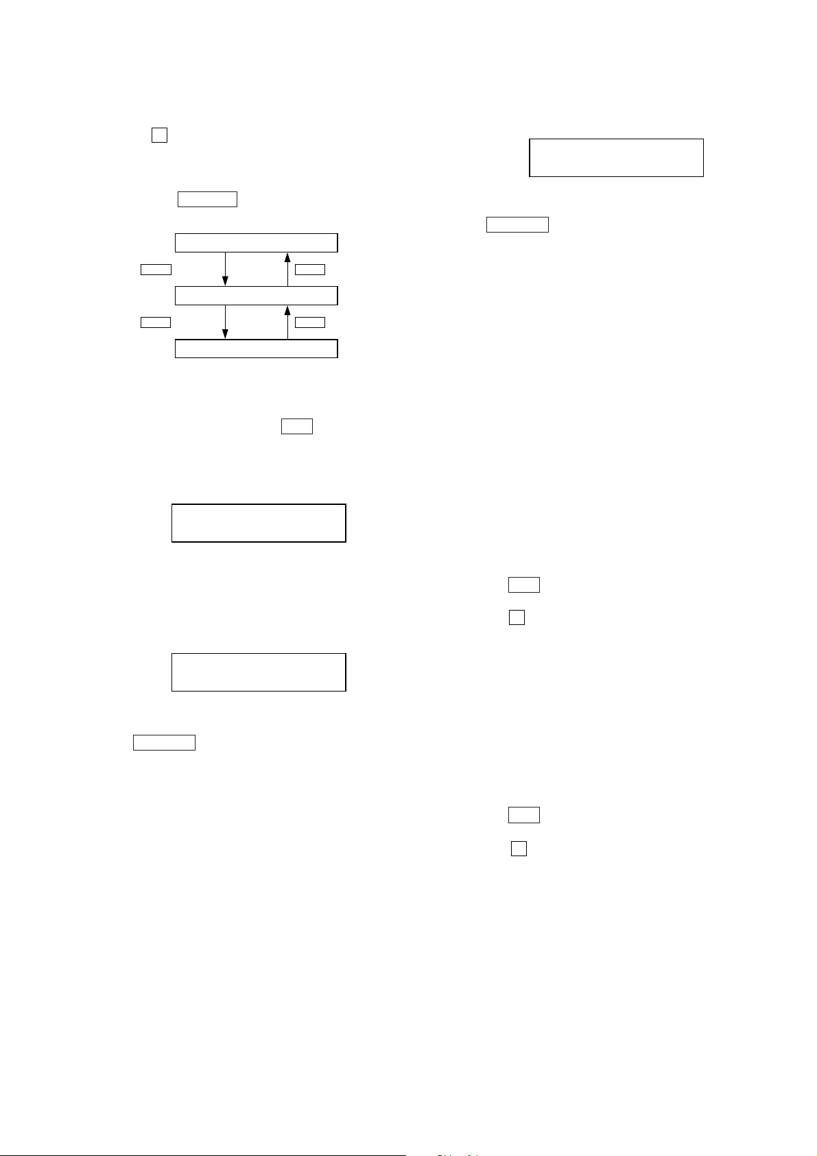
• This set can be disassembled in the order shown below.
3-1. DISASSEMBLY FLOW
SET
3-2.CASE
(Page 8)
3-3.LOADING PANEL ASSY
(Page 8)
3-4.FRONT PANEL ASSY
(Page 9)
HCD-GN660/GN770/GX9000
SECTION 3
DISASSEMBLY
3-5.CD MECHANISM DECK
(CDM74-F1BD81)
(Page 9)
3-9.TUNER PACK
(Page 11)
3-10.PRIMARY BOARD
(Page 12)
3-11.REAR PANEL
(Page 12)
3-14.POWER TRANSFORMER
(Page 14)
3-6.TAPE MECHANISM DECK,
GAME BOARD
(Page 10)
3-15.DRIVER BOARD,
SW BOARD
(Page 14)
3-12.MAIN BOARD
(Page 13)
3-7.CD SWITCH BOARD,
PANEL BOARD
(Page 10)
3-8.SWITCH BOARD
(Page 11)
3-16. BD BOARD,
OPTICAL PICK-UP
(KSM-215DCP/C2NP)
(Page 15)
3-17.SENSOR BOARD
(Page 15)
3-18.MOTOR (TB) BOARD
(Page 16)
3-19.MOTOR (LD) BOARD
(Page 16)
3-13.SURROUND BOARD,
PA BOARD
(Page 13)
7
HCD-GN660/GN770/GX9000
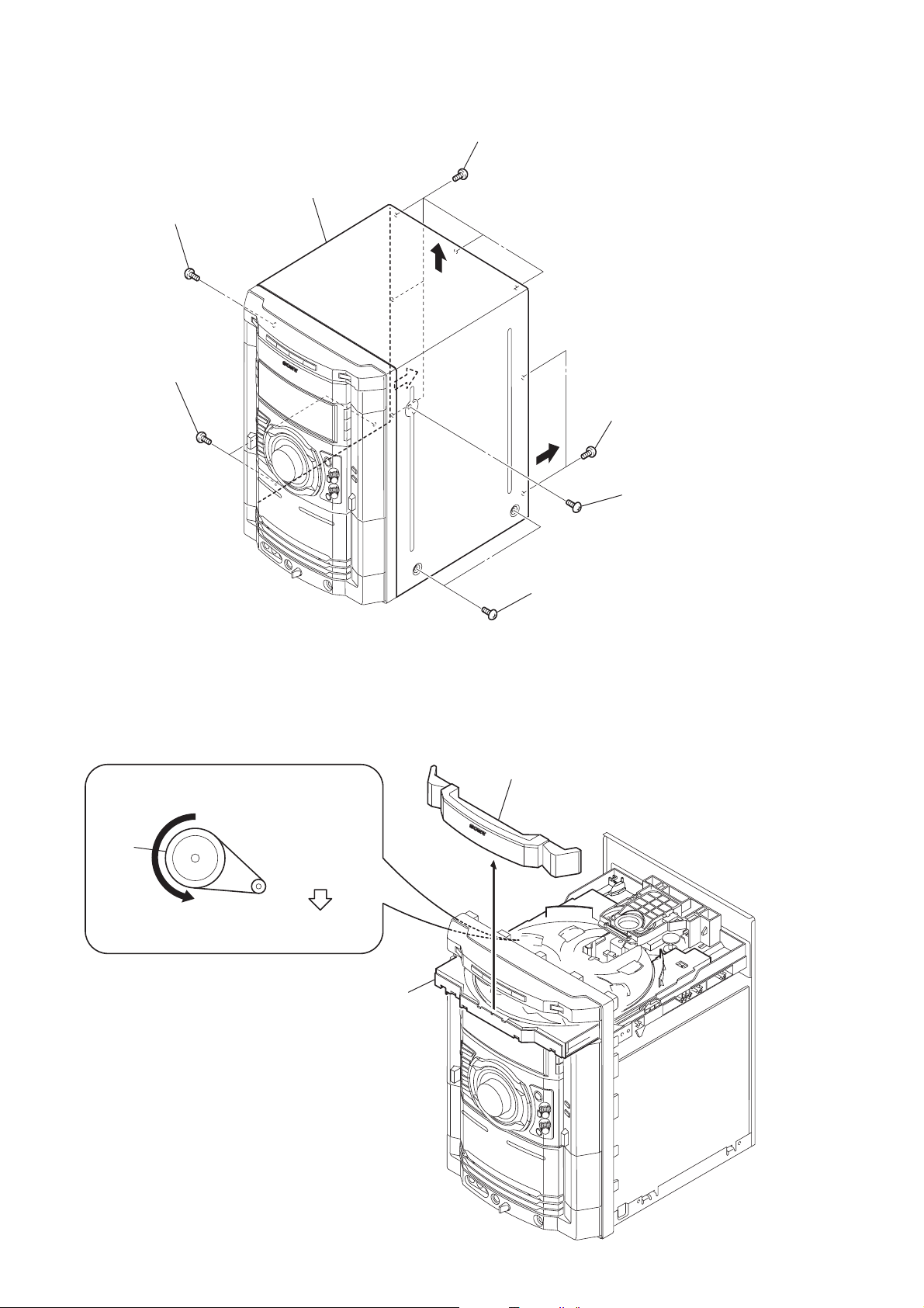
Note: Follow the disassembly procedure in the numerical order given.
3-2. CASE
2
screw (case 3 TP2)
(M3 x 12)
1
two screws
(case 3 TP2)
(M3 x 8)
7
case
3
(+BVTT3 x 6)
6
five screws
5
4
two screws
(+BVTT3 x 6)
2
screw (case 3 TP2)
(M3 x 12)
3-3. LOADING PANEL ASSY
CD mechanismdeck (CDM74-F1BD81)
1
Turn the pulley to the arrow direction.
Pulley
Front side
Pull out disc tray
2
4
loading panel assy
3
1
two screws
(case 3 TP2)
(M3 x 8)
8
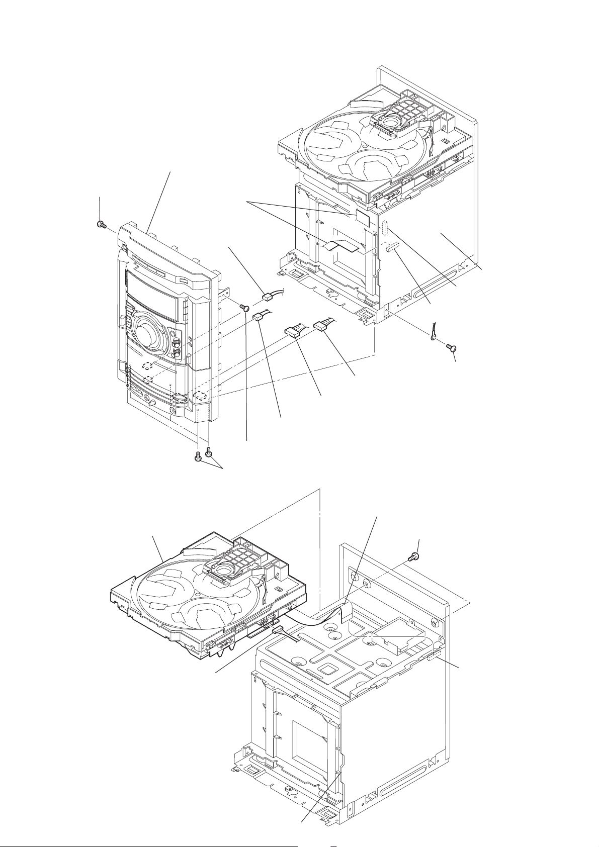
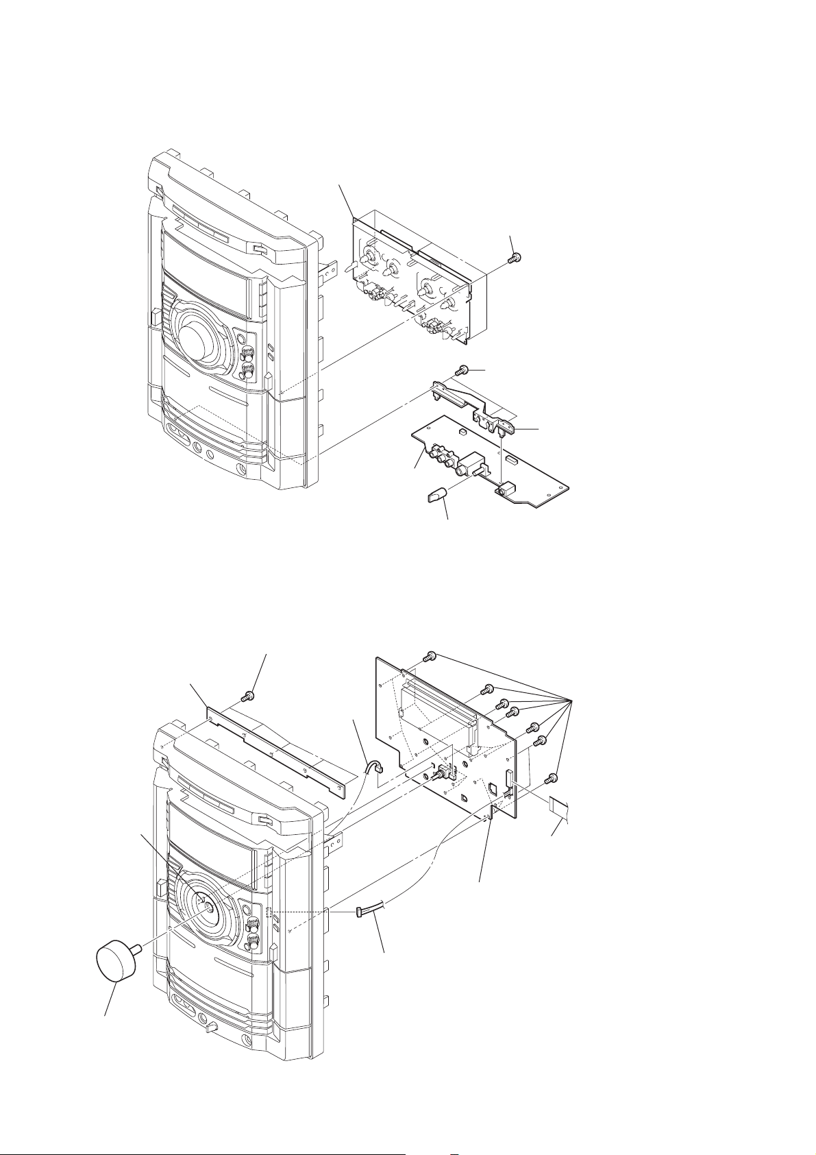
3-4. FRONT PANEL ASSY
)
)
9
front panel ASSY
3
screw (BVTP3 x 10)
1
two wires
(flat type)
8
from CN802 on
GAME board
HCD-GN660/GN770/GX9000
MAIN board
CN508
CN509
7
from deck A head
3
screw (BVTP3 x 10)
2
five screws (BVTP3 x 10)
3-5. CD MECHANISM DECK (CDM74-F1BD81)
4
CD mechanism deck
5
from deck B head
6
from CN801 on GAME board
2
wire (flat type) (27 core)
4
fcrew (BVTP3 x 10
1
two screws (BVTP3 x 10
3
CN701
MAIN board
CN201
9
HCD-GN660/GN770/GX9000
)
3-6. TAPE MECHANISM DECK, GAME BOARD
2
tape mechanism deck
1
five screws
(+BVTP2.6 x 8)
3
three screws
(+BVTP2.6 x 8)
3-7. CD SWITCH BOARD, PANEL BOARD
1
five screws
(+BVTP2.6 x 8)
2
CD SWITCH board
8
CN907
6
GAME board
5
knob (MIC)
4
bracket (MIC
5
nineteen screws
(+BVTP2.6 x 8)
10
6
claw
3
knob (VOL)
4
CN903
7
PANEL board
9
wire (flat type) (19 core)
from CN902
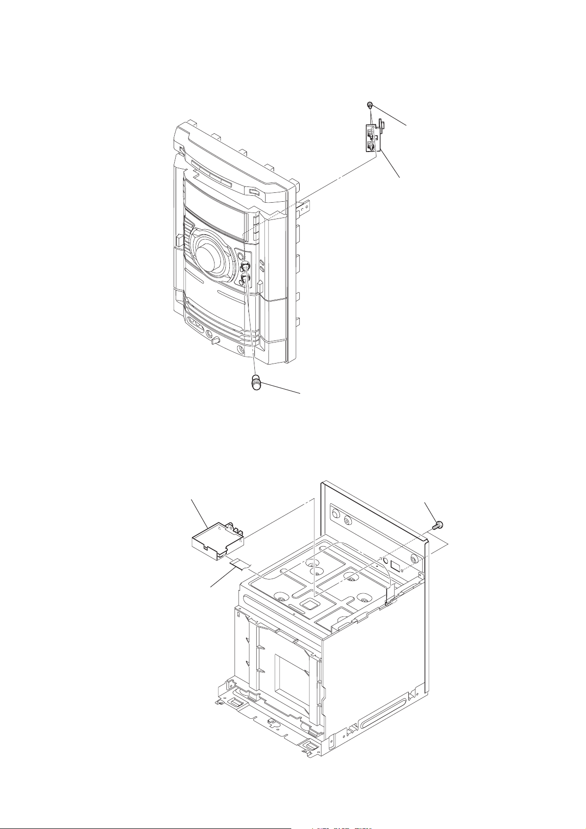
3-8. SWITCH BOARD
)
HCD-GN660/GN770/GX9000
2
two screws
(+BVTP2.6 x 8
3
SWITCH board
3-9. TUNER PACK
3
tuner pack
1
wire (flat type)
(11 core)
1
two knobs (AMS)
2
two screws
(+BVTT3 x 6)
11
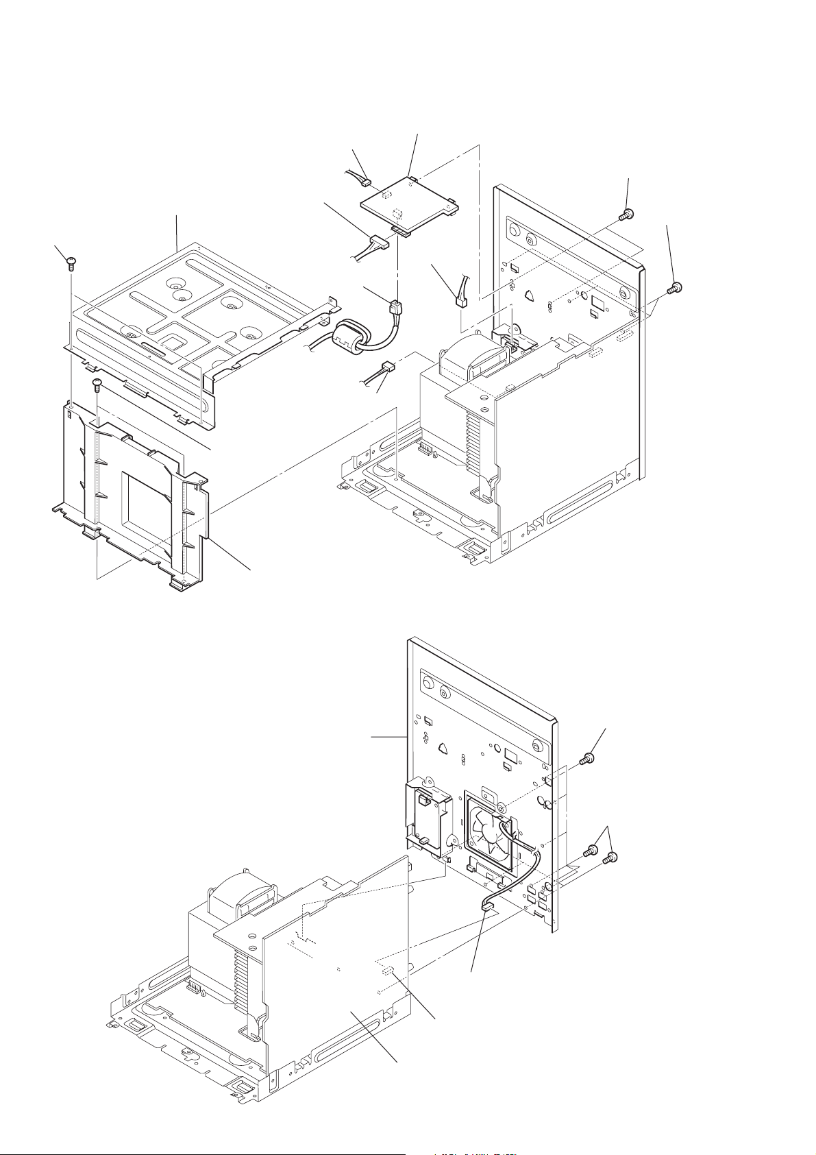
HCD-GN660/GN770/GX9000
)
3-10. PRIMARY BOARD
4
bracket, top
1
two screws
(BVTP3 x 10)
8
connector
7
9
connector
qa
CN201
CN1002
qs
PRIMARY board
0
CN101
3
two screws
(+BVTT3 x 6)
2
four screws
(BVTP3 x 6
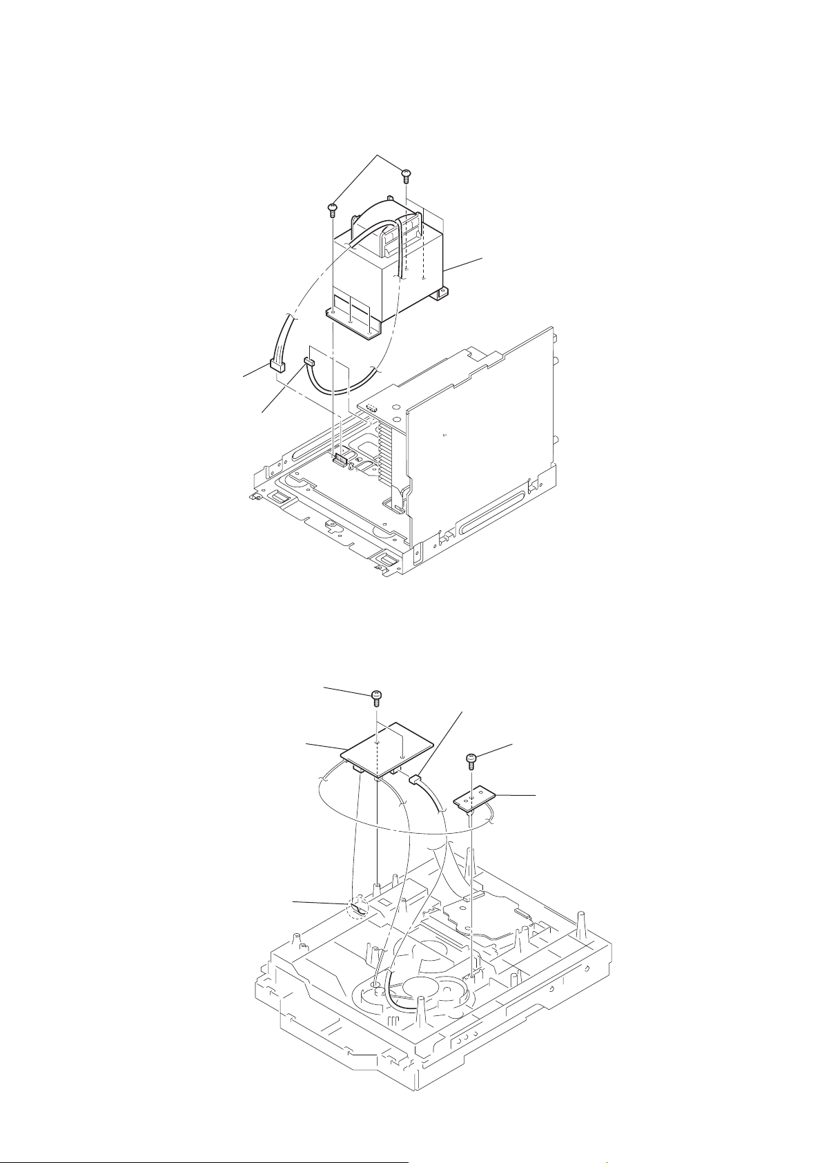
3-11. REAR PANEL
5
two screwss
(BVTP3 x 6)
6
bracket, sub
3
rear panel
with fan
2
screw
(+BVTT3 x 6)
1
nine screws
(+BVTP3 x 10)
12
MAIN board
CN503
4
Connector
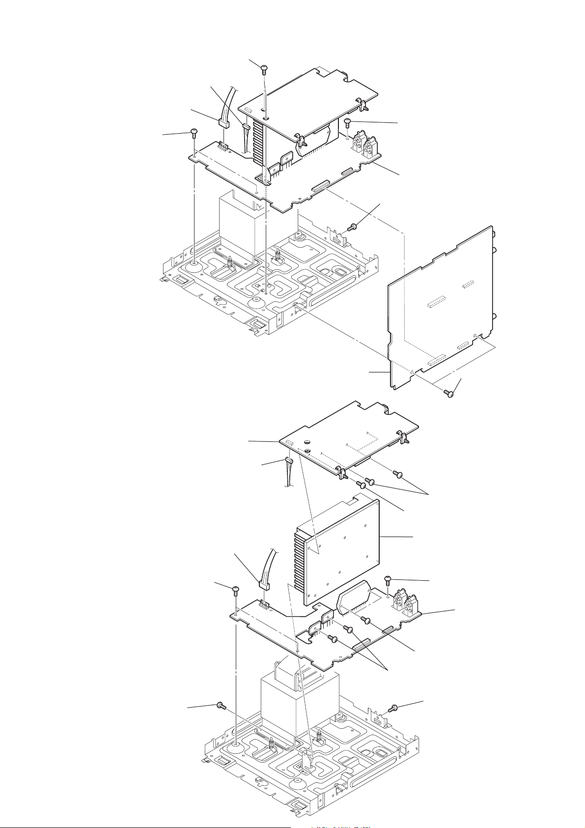
3-12. MAIN BOARD
1
6p (CN604)
3
two screws
(+BVTP3 x 6)
2
connector
4p (CN703)
connector
4
two screws
(+BVTP3 x 6)
HCD-GN660/GN770/GX9000
5
screw
(+BVTP3 x 6)
7
POWER board assy
6
screw
(+BVTP3 x 10)
3-13. SURROUND BOARD, PA BOARD
5
SURROUND board
2
connector
4p (CN703)
1
connector
6p (CN604)
0
two screws
(+BVTP3 x 6)
6
screw
(+BVTP3 x 10)
9
MAIN board
3
three screws
(+BVTP3 x 16)
4
screw
(+BVTP3 x 10)
qs
heat sink
qa
screw
(+BVTP3 x 10)
8
two screws
(+BVTP3 x 16)
9
two screws
(+BVTP3 x 10)
7
screw
(+BVTP3 x 10)
8
two screws
(+BVTP3 x 10)
qd
PA board
13
HCD-GN660/GN770/GX9000
r
3-14. POWER TRANSFORMER
1
connector
6p (CN604)
2
connector
4p (CN703)
3
six
screws
(+BVTT 4
× 8
)
4
power transforme
3-15. DRIVER BOARD, SW BOARD
1
two
(+BTTP (M2.6))
4
DRIVER
2
wire (flat type) 5p (CN702)
screws
board
3
connector
4p (CN703)
5
screw
(+BTTP (M2.6))
6
SW board
14
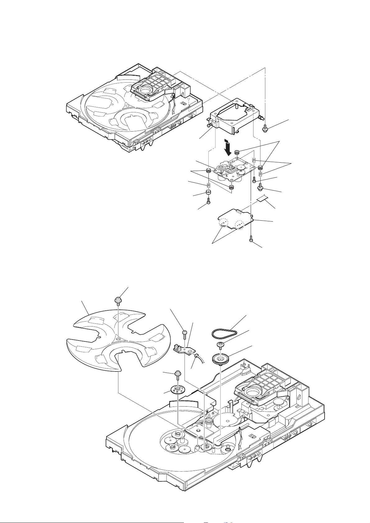
3-16. BD BAORD, OPTICAL PICK-UP (KSM-215DCP/C2NP)
2
h
older (213) ASSY
qh
optical pick-up
(KSM-215DCP/C2NP)
0
two
insulators
9
two
coil springs
(insulator)
8
t
wo stoppers (BU)
qa
HCD-GN660/GN770/GX9000
1
floating
(+PTPWH M2.6)
6
two
5
(insulator)
3
screw
(BVTT M2.6)
4
floating
(+PTPWH M2.6)
screw
insulators
two
coil springs
screw
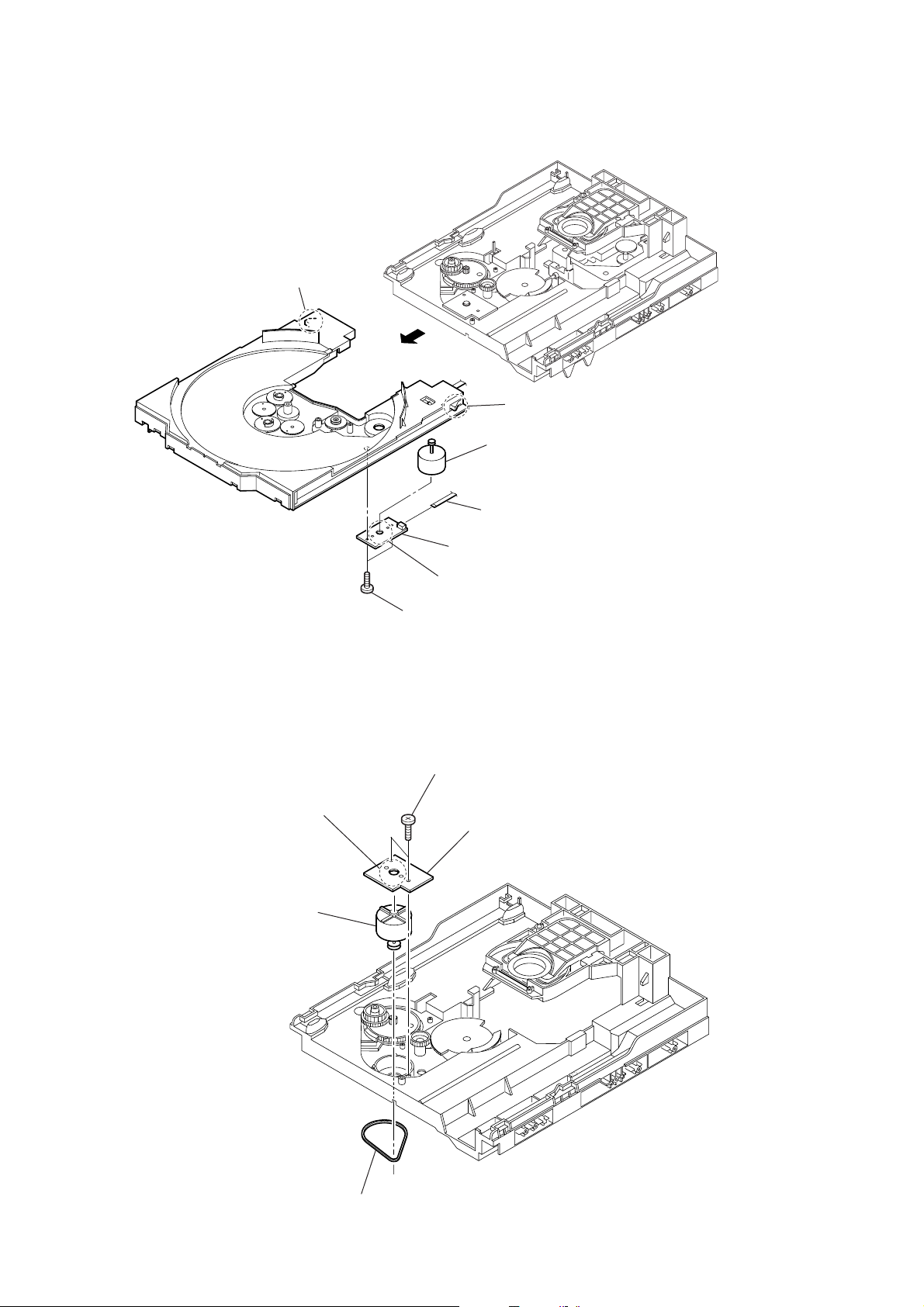
3-17. SENSOR BOARD
2
t
ray
qd
Remove the four solderings of motor.
1
floating
(+PTPWH M2.6)
6
floating
(+PTPWH M2.6)
screw
8
s
(+BTTP (M2.6))
screw
7
t
wo screws
(BVTT M2.6)
crew
0
9
(
SENSOR board
connector
CN731)
qf
qg
B
qs
s
crew (+BVTP 2.6x 8)
3
b
elt (table)
4
floating
(+PTPWH M2.6)
5
screw
p
ulley (table)
CN101 (flat type)
D board
7
g
ear (geneva)
15
HCD-GN660/GN770/GX9000
3-18. MOTOR (TB) BOARD
2
stopper
4
1
stopper
7
t
able motor assy (M741)
3-19. MOTOR (LD) BOARD
4
Remove the two solderings of motor.
5
l
oading motor assy (M751)
3
8
MOTOR (TB) board
6
Remove the two solderings of motor.
5
two
screws
(+BTTP (M2.6))
2
two
screws
(+BTTP (M2.6))
3
MOTOR (LD) board
wire (flat type) 5 core (CN742)
16
1
b
elt (loading)

SECTION 4
TEST MODE
HCD-GN660/GN770/GX9000
[GC TEST MODE]
• This mode is used to check the fluorescent indicator tube, LED,
model, destination, software version, volume, key jog, encoder
and VACS level.
Procedure:
1. Press x button, [ENTER] button and [DISC 2] button
simultaneously.
2. All LEDs and segments in fluorescent indicator tube are lighted
up.
3. When you want to enter the software version display mode,
press [DISC 1] button. The model and destination are displayed.
4. Each time [DISC 1] button is pressed, the display changes from
MC version, GC version, CD version, CDDM version, CDMA
version, CDMB version, BDA version, BDB version, ST
version, T A version, TM version and TC version in this order ,
and returns to the MC version display.
5. When [DISC 3] button is pressed while the version numbers
are being displayed except model and destination, the date of
the software creation appear. When [DISC 3] button is pressed
again, the display returns to the software version display. When
[DISC 1] button is pressed while the date of the software
creation is being displayed, the date of the software creation
is displayed in the same order of software version display.
6. Press [DISC 2] button, the key check mode is activated.
7. In the key check mode, the fluorescent indicator tube displays
“K 0 J 0 V 0 E 0”.
Each time a button is pressed, “K” value increases. However,
once a button has been pressed, it is no longer taken into
account.
“J” value increases in the manner of 0,1, 2, 3 ... if [MULTI
JOG] knob is turned clockwise, or it decreases in the manner
of 0, 9, 8, 7 ... if [MULTI JOG] knob is turned counter -clockwise.
“V” value increases in the manner of 0,1, 2, 3 ... if [VOLUME]
knob is turned clockwise, or it decreases in the manner of 0,
9, 8, 7 ... if [VOLUME] knob is turned counter-clockwise.
“E” value increases in the manner of 0,1, 2, 3 ... if
knob is turned clockwise, or it decreases in the manner of 0,
9, 8, 7 ... if
8. When [DISC 3] button is pressed after all LEDs and segments
in fluorescent indicator tube light up, the fluorescent indicator
tube displays “VACS A+B APCC”. A is VACS level which is
trigger by signal level, B is VACS level which is trigger by
temperature and CC is VACS level which is trigger by
APVACS (Abuse Protection VACS).
9. When [EX-CHANGE/DISC SKIP] button is pressed after all
LEDs and segments in fluorescent indicator tube light up,
alternate segments in fluorescent indicator tube would light
up. If you press [EX-CHANGE/DISC SKIP] button again, another
half of alternate segments in fluorescent indicator tube would
light up. Pressing [EX-CHANGE/DISC SKIP] button again
would case all segments lights up.
10. To release this mode, press three buttons in the same manner
as step 1, or disconnect the power cord.
[MC TEST MODE]
• This mode is used to check operations of the respective sections
of Amplifier, Tuner, and Tape.
Procedure:
* To enter MC Test Mode
1. Press x button, [ENTER] button and [DISC 3] button
simultaneously.
2. The CD ring indicators TAPE A and TAPE B indicators flash
on the fluorescent indicator tube. The function is changed to
VIDEO.
.
knob is turned counter-clockwise.
>
.
>
* Check of Amplifier
1. Press [EQ EDIT] button repeatedly until a message “GEQ
MAX” appears on the fluorescent indicator tube. GEQ
increases to its maximum.
2. Press [EQ EDIT] button repeatedly until a message “GEQ MIN”
appears on the fluorescent indicator tube. GEQ increases to
its minimum.
3. Press [EQ EDIT] button repeatedly until a message “GEQ
FLAT” appears on the fluorescent indicator tube. GEQ set to
flat.
4. When the [VOLUME] knob is turned clockwise even slightly,
the sound volume increases to its maximum and a message
“VOLUME MAX” appears.
5. When the [VOLUME] knob is turned counter-clockwise even
slightly, the sound volume decreases to its minimum and a
message “VOLUME MIN” appears.
* Tape function
1. When a tape is inserted in Deck B and recording is started, the
function is changed to VIDEO automatically . When [CD SYNC]
button is pressed during recording in function, ALC (Automatic
Logic Control) is turned on.
2. During recording, turn
rotation will change the function to T APE B and rewind Tape
B until the recording start position and playback of Tape B is
started. If the [REC PAUSE/ START] button is pressed for a
pause and pressed again to resume recording during recording
time, when tape deck B is rewind, tape deck B will be rewind
until the position where the pause is applied.
* AMS Test Mode
1. Select the function “TAPE A” or “TAPE B”.
2. Select Loop or Relay direction mode by pressing the
[DIRECTION TUNER MEMORY] button. Insert a test tape AMS110A or AMS-120 to selected tape deck.
3. Press the [AMP MENU] button to enter the AMS test mode.
4. After the test tape is rewind to the beginning of the tape, the
AMS+ is checked, and the mechanism is shut off after detecting
the AMS signal twice.
5. Then the AMS- is checked and the mechanism is shut of f after
detecting the AMS signal twice.
6. When the check is complete, a message of either OK or NG
appears.
* To release MC Test mode.
1. To release this mode, press
2. The cold reset is enforced at the same time.
[COLD RESET]
• The cold reset clears all data including preset data stored in
the RAM to initial conditions. Execute this mode when
returning the set to the customer.
Procedure:
1. Press x button, [ENTER] button, and
simultaneously.
2. The fluorescent indicator tube becomes blank for a while, and
the set is reset.
m
knob to counter clockwise
M
button.
?/1
?/1
button
17
HCD-GN660/GN770/GX9000
[VACS ON/OFF]
• This mode is used to switch ON and OFF the V ACS (Variable
Attenuation Control System).
Procedure:
1. Press
2. Press [ENTER] button and [GAME MIXING] button
simultaneously. The message “VACS OFF” or “VACS ON”
appears.
[TUNER STEP CHANGE]
• The step interval of AM channels can be toggled between 9
kHz and 10 kHz.
Procedure:
1. Press
2. Press [TUNER/BAND] button to select the “AM”.
3. Press
4. Press [ENTER] button and
system will turn ON automatically. The message “AM 9k
STEP” or AM 10k STEP” appears and thus the channel step
is changed.
[CD SERVICE MODE]
• This mode let you move the CD sled motor freely. Use this
mode when you want to clean the optical pick-up.
button to turn the set ON.
?/1
button to turn the set ON.
?/1
button to turn the set OFF.
?/1
button simultaneously . The
?/1
[AGING MODE]
This mode can be used for operation check of CD section.
• If an error occurs, the aging operation would stops and the
status is displayed.
• If there are no error occurs, the aging operation would
continues repeatedly.
Procedure:
1. Press
2. Select CD function.
3. Load three discs on the disc tray.
4. Press [PLAY MODE] button to select the “ALL DISCS” mode,
and press the [REPEAT] button to select “REPEAT OFF” mode.
5. Press x button, [ENTER] button, and [EX-CHANGE/DISC
SKIP] button simultaneously.
6. Aging operation is started.
7. To release this mode, press
power cord to turn the power OFF.
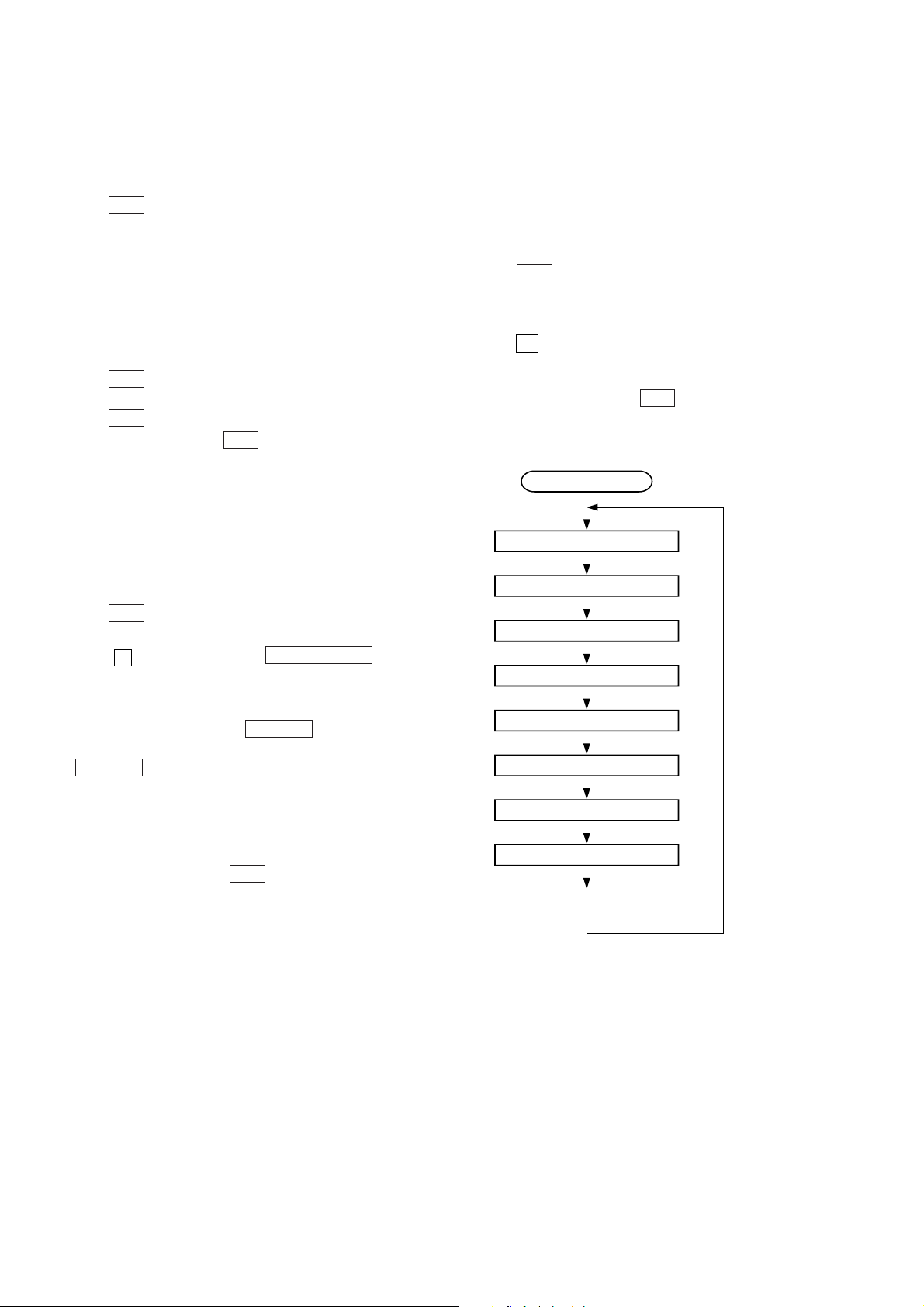
Aging mode sequence:
button to turn the set ON
?/1
Start (from disc 1)
Disc chucking
button or disconnect the
?/1
Procedure:
1. Press
2. Select CD function.
3. Press x , [ENTER] button, and
simultaneously.
4. The CD service mode is activated. The message “SERVICE
MODE” appears.
5. With the CD in stop status, turn
rotation to move the optical pick-up to outside track, or turn
m
inside track. The message “SLED OUT” or “SLED IN”
appears.
6. To turn on or off the laser, press [PLAY MODE] button. The
message “LASER ON” or “LASER OFF” appears on the
fluorescent indicator tube.
7. To release this mode, press
button to turn the set ON.
?/1
knob to counterclockwise rotation to move to
M
?/1
Z
m
button.
OPEN/CLOSE
knob to clockwise
M
button
TOC reading
Play first track for 2 seconds
Play last track for 2 seconds
EX-CHANGE open/close
Open the disc tray
Disc skip
Close the disk tray
Change the next disc.
18
HCD-GN660/GN770/GX9000
• Display when an error occurred (CD Error Code Mode)
Procedure:
1. Press x button, [ENTER] button and [DISC 1] button
simultaneously to enter the error code display mode.
2. The fluorescent indicator tube displays the number of total
error.
3. Each time
m
knob is rotated, display change as
M
below.
Display of total error
>
>
+
direction
Display of Mechanical errors
+
direction
Display of no disc errors
–
–
.
.
direction
direction
4. To clear the error record, operate the cold reset. (Refer to the
“MC COLD RESET”)
5. To release this mode, press the
button or disconnect
?/1
the power plug to turn the power OFF.
1) Display of total error
Display
EM**ED**
3) Display of no disc errors
Display
D*$$%%&&##00
D*: The number of mechanical error (“00” is latest one)
(Rotate
.
error)
$$: Error type
01: Focus error
02: GFS error
03: Setup error
%%: Not used
&&:
00: No disc judgment without chucking retry.
01: No disc judgment after chucking retry.
##: The state when judged as no disc
01: Stop
02: Setup
03: TOC reading
04: Access
05: Playback
06: Pause
07: Manual search (Play)
08: Manual search (Pause)
[CD REPEAT 5 LIMIT OFF MODE]
• The number of repeat for CD playback is 5 times when the
repeat mode is “REPEAT ALL”. This mode enables CD to
repeat playback for limitless times.
knob in the direction of either to display next
>
EM**: The number of mechanical errors.
ED**: The number of no disc errors after chucking the disc.
2) Display of mechanical errors
Display
M*$$%%&&##00
M*: The number of mechanical error (“00” is latest one)
(Rotate
.
error)
$$: Not used
%%: Loading related error (Second figure is not used)
D: Stop by the problem other than mechanical problem while
closing.
E: Stop by the problem other than mechanical problem while
opening.
C: Stop by the problem other than mechanical problem while
chucking up.
F: Stop by the problem other than mechanical problem while
chucking down.
&&: Emerging error
01: Stop while chucking up.
02: Stop while chucking up.
03: Time-out of EX-CHANGE open.
05: Time-out of EX-CHANGE close.
##: Not used
knob in the direction of either to display next
>
Procedure:
1. Press
button to turn the set ON.
?/1
2. Select CD function.
3. Press x button, [EQ EDIT] button and [CD] button
simultaneously to enter the CD repeat 5 limit off mode and
the fluorescent indicator tube displays “LIMIT OFF”.
4. To release this mode, operate the cold reset. (Refer to the “MC
COLD RESET”)
[CD SHIP MODE (WITH MEMORY CLEAR)]
• This mode moves the optical pick-up to the position durable
to vibration and clears all data including preset data stored in
the RAM to initial conditions. Use this mode when returning
the set to the customer after repair.
Procedure:
1. Press
button to turn the set ON.
?/1
2. Select CD function.
3. Press x button, [ENTER] button and [GAME] button
simultaneously. The set will power off automatically.
4. After the “STANDBY” blinking display finish, a message
“LOCK” is displayed on the fluorescent indicator tube and
the CD ship mode is set.
19

HCD-GN660/GN770/GX9000
[CD SHIP MODE (WITHOUT MEMORY CLEAR)]
• This mode moves the optical pick-up to the position durable
to vibration. Use this mode when returning the set to the
customer after repair.
Procedure:
1. Press
2. Select CD function.
3. Press [CD] button and
will power off automatically.
4. After the “STANDBY” blinking display finish, a message
“LOCK” is displayed on the fluorescent indicator tube and
the CD ship mode is set.
[CD POWER MANAGE]
• This mode let you switch on or off power supply to the BU
during TUNER function.
• When CD POWER is set to OFF, the power supply to the BU
is cut off during TUNER function. It will increase the time
taken to access CD when function change from TUNER to
CD but it will improve tuner reception.
• When CD POWER is set to ON, the power supply to the BU
is not cut off during TUNER function. It will reduce the time
taken to access CD when function change from TUNER to
CD but it will decrease tuner reception performance.
Procedure:
1. Press
2. Select CD function.
3. Press
4. Press x button and
will power on automatically.
5. The message “CD POWER ON” or “CD POWER OFF” will
be displayed on the fluorescent indicator tube.
button to turn the set ON.
?/1
?/1
button to turn the set ON.
?/1
button to turn the set OFF.
?/1
?/1
button simultaneously. The set
button simultaneously. The set
[CD TRAY LOCK MODE]
• This mode let you lock the disc trays. When this mode is
activated, the disc tray will not open when
button or [EX-CHANGE/DISC SKIP] button is pressed. The
message “LOCKED” will be displayed in the will be displayed
on the fluorescent indicator tube.
Procedure:
1. Press
2. Select CD function.
3. Press x button and
simultaneously and hold down until “LOCKED” or
“UNLOCKED” displayed on the fluorescent indicator tube
(around 5 seconds).
[VIDEO/MD SWITCHING]
• This mode let you switch from VIDEO to MD and vice-versa.
Procedure:
1. Press
2. Select VIDEO function.
3. Press [VIDEO/MD] button and
The function will change to MD. Press the same buttons again
to change from MD to VIDEO.
button to turn the set ON.
?/1
button to turn the set ON.
?/1
OPEN/CLOSE
Z
?/1
OPEN/CLOSE
Z
button
button simultaneously.
20
HCD-GN660/GN770/GX9000
SECTION 5
MECHANICAL ADJUSTMENTS
Precaution
1. Clean the following parts with a denatured alcohol-moistened
swab:
record/playback heads pinch rollers
erase head rubber belts
capstan idlers
2. Demagnetize the record/playback head with a head
demagnetizer.
3. Do not use a magnetized screwdriver for the adjustments.
4. After the adjustments, apply suitable locking compound to
the parts adjusted.
5. The adjustments should be performed with the rated power
supply voltage unless otherwise noted.
Torque Measurement
Mode Torque meter Meter reading
3.06 N • m to 6.96 N • m
FWD CQ-102C 31 to 71 g • cm
(0.43 – 0.98 oz • inch)
FWD
back tension
REV CQ-102RC 31 to 71 g • cm
REV
back tension
FF/REW CQ-201B 71 to 143 g • cm
FWD tension CQ-403A 100 g or more
REV tension CQ-403R 100 g or more
CQ-102C 2 to 6 g • cm
CQ-102RC 2 to 6 g • cm
0.19 N • m to 0.58 N • m
(0.02 – 0.08 oz • inch)
3.06 N • m to 6.96 N • m
(0.43 – 0.98 oz • inch)
0.19 N • m to 0.58 N • m
(0.02 – 0.08 oz • inch)
6.96 N • m to 14.02 N • m
(0.98 – 1.99 oz • inch)
9.80 N • m
(3.53 oz or more)
9.80 N • m
(3.53 oz or more)
SECTION 6
ELECTRICAL ADJUSTMENTS
DECK SECTION
1. Demagnetize the record/playback head with a head
demagnetizer.
2. Do not use a magnetized screwdriver for the adjustments.
3. After the adjustments, apply suitable locking compound to the
parts adjust.
4. The adjustments should be performed with the rated power
supply voltage unless otherwise noted.
5. The adjustments should be performed in the order given in
this service manual. (As a general rule, playback circuit
adjustment should be completed before performing recording
circuit adjustment.)
6. The adjustments should be performed for both L-CH and RCH.
7. Switches and controls should be set as follows unless otherwise
specified.
•Test Tape
Tape Signal Used for
P-4-A100 10 kHz, –10 dB Azimuth Adjustment
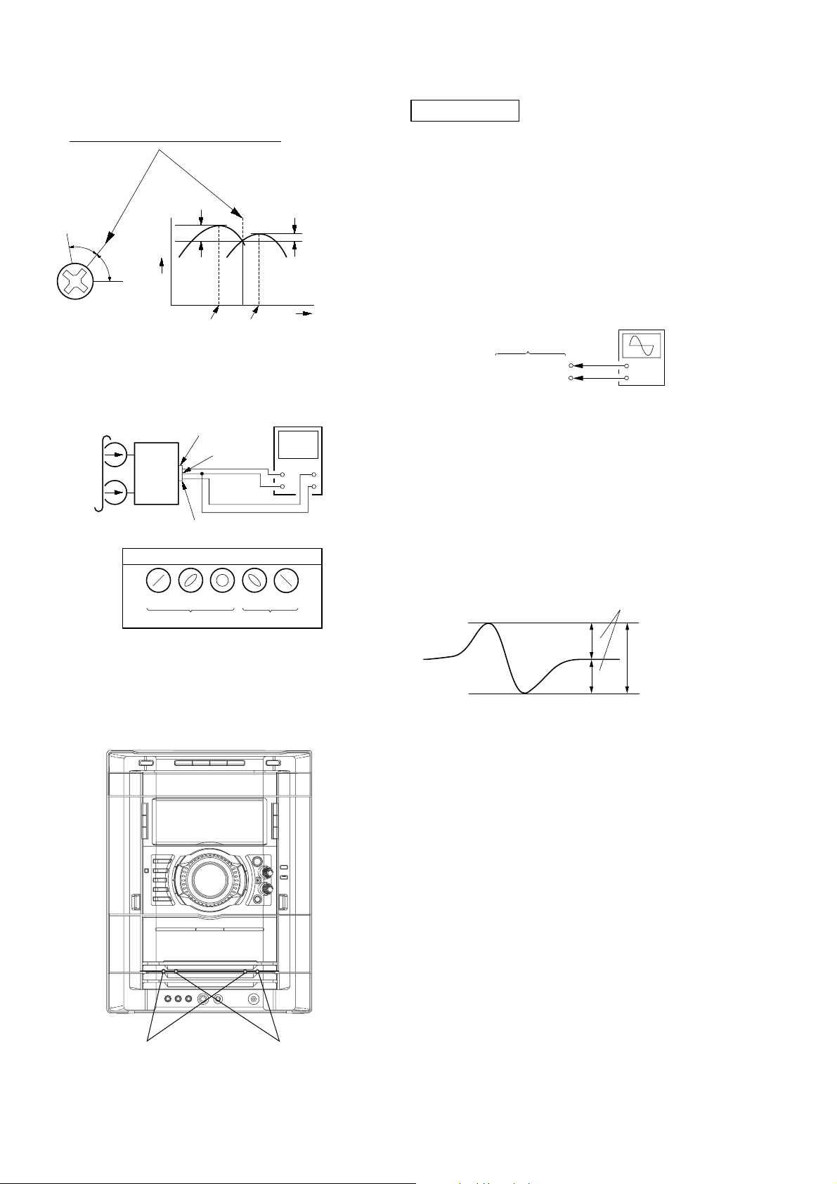
RECORD/PLAYBACK HEAD AZIMUTH ADJUST-MENT
DECK A DECK B
Note: Perform this adjustments for both decks
Procedure:
1. Mode: Playback
test tape
P-4-A100
(10 kHz, –10 dB)
0 dB=0.775 V
MAIN board
CN510
Pin
1
(L-CH)
3
(R-CH)
Pin
set
MAIN board
CN510
2
(GND)
Pin
level meter
+
–
21
HCD-GN660/GN770/GX9000
e
hH
A
A
2. Turn the adjustment screw and check output peaks. If the peaks
do not match for L-CH and R-CH, turn the adjustment screw
so that outputs match within 1dB of peak.
Output
level
within
1dB
L-CH
peak
R-CH
peak
within
1dB
Screw
position
L-CH
peak
Screw
position
R-CH
peak
3. Mode: Playback
test tape
P-4-A100
(10 kHz, –10 dB)
L-CH
MAIN
board
CN301
set
R-CH
waveform of oscilloscope
pin
L
R
pin
1
pin
3
2
oscilloscop
H
V
CD SECTION
Note:
1. CD Block is basically designed to operate without adjustment.
Therefore, check each item in order given.
2. Use YEDS-18 disc (3-702-101-01) unless otherwise indicated.
3. Use an oscilloscope with more than 10MW impedance.
4. Clean the object lens by an applicator with neutral detergent
when the signal level is low than specified value with the
following checks.
S-curve Check
Connection:
oscilloscope
CD board
TPO102 (FE1)
TP117 (VC)
Procedure:
1. Connect an oscilloscope to test point TPO102 (FE1) and TP
117(VC) on the CD board.
2. Turn the power on.
3. Put the disc (YEDS-18) in and turned power switch on again
and actuate the focus search. (actuate the focus search when
disc table is moving in and out)
4. Check the oscilloscope waveform (S-curve) is symmetrical
between A and B. And confirm peak to peak level within 2.4
± 1 Vp-p.
+
–
in phase 45°90°135°180
good
°
wrong
4. After the adjustments, apply suitable locking compound to
the pats adjusted.
Adjustment Location: Playback Head (Deck A).
Record/Playback/Erase Head (Deck B).
S-curve waveform
symmetry
A
within 2.4
B
Note:
•Try to measure several times to make sure than the ratio
of A : B or B : A is more than 10 : 7.
•Take sweep time as long as possible and light up the
brightness to obtain best waveform.
Checking Location: CD board (SIDE B)
(See page 24.)
±
1 Vp-p
forward
reverse
22
HCD-GN660/GN770/GX9000
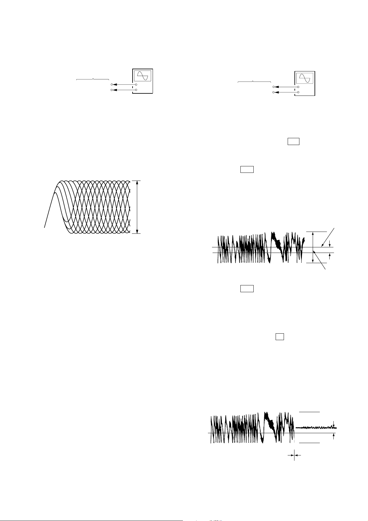
RFAC Level Check
Connection:
oscilloscope
CD board
TP124 (RFAC)
TP117 (VC)
+
–
Procedure:
1. Connect an oscilloscope to test point TP124 (RFAC) and TP
117(VC) on the CD board.
2. Turn the power on.
3. Put the disc (YEDS-18) in to playback the number five track.
4. Confirm that oscilloscope waveform is clear and check RF AC
signal level is correct or not.
Note: A clear RFAC signal waveform means that the shape “◊” can be
RFAC signal waveform
clearly distinguished at the center of the waveform.
VOLT/DIV: 200 mV
TIME/DIV: 500 ns
level: 0.9 ± 0.4 Vp-p
E-F Balance Check
Connection:
oscilloscope
CD board
TPO103 (TE1)
TP117 (VC)
+
–
Procedure:
1. Connect an oscilloscpe to test point TPO103 (TE1) and TP1 17
(VC) on the CD board.
2. Turn the power on.
3. Select the function “CD”.
4. Press three buttons of [ENTER], M , and
[SURRUUND MODE] simultaneously to set the CD service
mode.
5. Put the disc (YEDS-18) in to playback the number five track.
6. Press the . button. The message “TRAVERSE” is
displayed. (The tracking servo and the sledding servo are
turned OFF)
7. Check the level B of the oscilliscope's waveform and the A
(DC voltage) of the center of the Traverse waveform.
Confirm the following :
A/B x 100 = less than ± 22%
Traverse Wav ef orm
Center of
the waveform
Checking Location: CD board (SIDE B)
(See page 24.)
B
0V
level: 1.0 ± 0.5 Vp-p
8. Press the . button. The message “TRAVERSE” is
A (DC
voltage)
displayed. (The tracking servo and sledding servo are turned
ON)
Confirm the C (DC voltage) is almost equal to the A (DC
voltage) is step 5.
9. To exit from this mode, perform as follows.
1) Move the optical pick-up to the most inside track.
2) Press three buttons of x , [CLEAR], and [DISPLAY]
simultaneously. (cold reset)
Notes:
• Always move the optical pick-up to most inside track
when exiting from this mode. Otherwise, a disc will not
be unloaded.
• Do not run the sled motor excessively , otherwise the gear
can be chipped.
Traverse Wav ef orm
0V
Tracking servo
Sled servo
OFF
Tracking servo
Sled servo
ON
Checking Location: CD board (SIDE B) (See page 24.)
C (DC
voltage)
23
HCD-GN660/GN770/GX9000
Checking Location:
– CD BOARD (SIDE B) –
TP117 (VC)
JPO103 (TE1)
JPO102 (FE1)
IC101
TP124 (RFAC)
24
 Loading...