

Sony HCDCP-505 Service manual
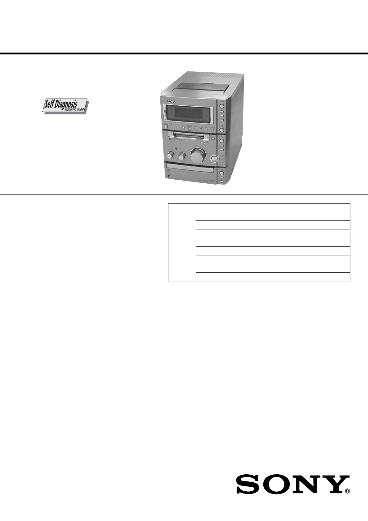
HCD-CP505
SERVICE MANUAL
Ver. 1.3 2005.02
HCD-CP505 is the Amplifier, CD player, MD
deck, Tape player and Tuner section in
CMT-CP505MD.
Model Name Using Similar Mechanism NEW
CD
Section
MD
Section
Tape deck
Section
CD Mechanism Type CDM55G-30BBD61B
Base Unit Type BU-30BBD61B
Optical Pick-up Type A-MAX. 3
Model Name Using Similar Mechanism NEW
MD Mechanism Type MDM-7S2C
Optical Pick-up Type KMS-262E
Model Name Using Similar Mechanism NEW
Tape Transport Mechanism Type CMAL1Z-221A
AEP Model
UK Model
E Model
Chinese Model
Amplifier section
European model:
DIN power output (rated): 30 + 30 W
Continuous RMS power output (reference):
Music power output (reference):
Other models:
The following measured at 230 V AC, 60 Hz
DIN power output (rated): 25 + 25 W
Continuous RMS power output (reference):
The following measured at 220 V AC, 60 Hz
DIN power output (rated): 22 + 22 W
Continuous RMS power output (reference):
(6 ohms at 1 kHz, DIN)
35 + 35 W
(6 ohms at 1 kHz, 10%
THD)
70 + 70 W
(6 ohms at 1 kHz, DIN)
30 + 30 W
(6 ohms at 1 kHz, 10%
THD)
(6 ohms at 1 kHz, DIN)
28 + 28 W
(6 ohms at 1 kHz, 10%
THD)
SPECIFICATIONS
Inputs
ANALOG IN: Sensitivity 250 mV,
(phono jacks) impedance 47 kilohms
DIGITAL OPTICAL IN (supported sampling
frequencies: 32 kHz, 44.1 kHz and 48 kHz)
Outputs
PHONES: Accepts headphones with
SPEAKER: accepts impedance of 6 to
CD player section
System Compact disc and digital
Laser Semiconductor laser
Frequency response 2 Hz – 20 kHz
an impedance of 8 ohms
or more
16 ohms.
audio system
(λ=780 nm)
Emission duration:
continuous
MICRO HI-FI COMPONENT SYSTEM
MD deck section
System Minidisc digital audio
Laser Semiconductor laser
Sampling frequency 44.1 kHz
Frequency response 5 Hz – 20 kHz
Tape deck section
Recording system 4-track 2-channel stereo
Frequency response 50 – 13,000 Hz (±3 dB),
— Continued on next page —
system
(λ=780 nm)
Emission duration:
continuous
using Sony TYPE I
cassettes
9-874-070-04
2005B16-1
© 2005.02
Sony Corporation
Personal Audio Group
Published by Sony Engineering Corporation
HCD-CP505
Tuner section
FM stereo, FM/AM superheterodyne tuner
FM tuner section
Tuning range 87.5 - 108.0 MHz
Antenna FM wire antenna
Antenna terminals 75 ohms unbalanced
Intermediate frequency 10.7 MHz
AM tuner section
Tuning range
European model: 531 - 1,602 kHz
Other models: 530 - 1,710 kHz
Antenna AM loop antenna, external
Intermediate frequency 450 kHz
(50-kHz step)
(with the tuning interval
set at 9 kHz)
(with the tuning interval
set at 10 kHz)
531 - 1,602 kHz
(with the tuning interval
set at 9 kHz)
antenna terminal
General
Power requirements
European model: 230 V AC, 50/60 Hz
Other models: 110 – 120 V or
Power consumption
European model: See the name plate
Other models: See the name plate
Dimensions (w/h/d) incl. projecting parts and controls
Amplifier/Tuner/Tape/MD/CD section:
Speaker: Approx. 152 × 240 ×
220 – 240 V AC,
50/60 Hz
Adjustable with voltage
selector
0.3 watts (at the Power
Saving mode)
Approx. 175 × 240 ×
341.5 mm
258.5 mm
Mass
Amplifier/Tuner/Tape/MD/CD section:
Speakers: Approx. 2.6 kg net per
Supplied accessories Remote (1)
Optional accessories Sony PC connection kit
Design and specifications are subject to change
without notice.
Approx. 6.1 kg
speaker
R6 (size AA) batteries (2)
AM loop antenna (1)
FM lead antenna (1)
(See the catalogue and
other promotional
materials for the release
date.)
The optional accessories
for this system are subject
to change without notice.
For details, consult your
nearest Sony dealer.
NOTES ON HANDLING THE OPTICAL PICK-UP
BLOCK OR BASE UNIT
The laser diode in the optical pick-up block may suffer electrostatic
break-down because of the potential difference generated by the
charged electrostatic load, etc. on clothing and the human body.
During repair, pay attention to electrostatic break-down and also
use the procedure in the printed matter which is included in the
repair parts.
The flexible board is easily damaged and should be handled with
care.
FOR CD
NOTES ON LASER DIODE EMISSION CHECK
The laser beam on this model is concentrated so as to be focused on
the disc reflective surface by the objective lens in the optical pickup block. Therefore, when checking the laser diode emission,
observe from more than 30 cm away from the objective lens.
FOR MD
NOTES ON LASER DIODE EMISSION CHECK
Never look into the laser diode emission from right above when
checking it for adjustment. It is feared that you will lose your sight.
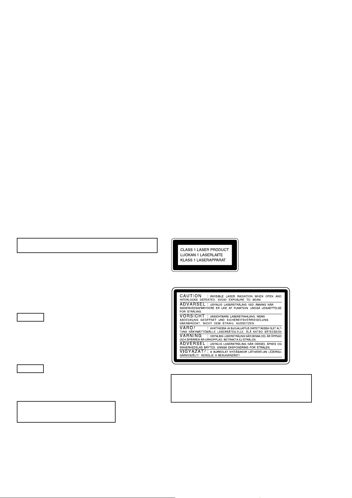
Laser component in this product is capable
of emitting radiation exceeding the limit for
Class 1.
This appliance is
classified as a CLASS 1
LASER product. This
label is located on the
rear exterior.
The following caution label is located inside the apparatus.
CAUTION
Use of controls or adjustments or performance of procedures
other than those specified herein may result in hazardous radiation
exposure.
Notes on chip component replacement
•Never reuse a disconnected chip component.
• Notice that the minus side of a tantalum capacitor may be
damaged by heat.
Unleaded solder
Boards requiring use of unleaded solder are printed with the leadfree mark (LF) indicating the solder contains no lead.
(Caution: Some printed circuit boards may not come printed with
the lead free mark due to their particular size.)
2

TABLE OF CONTENTS
HCD-CP505
1. SERVICING NOTES ····················································· 10
2. GENERAL ········································································ 12
3. DISASSEMBLY ······························································ 15
3-1. Top Panel Section ··························································16
3-2. Cassette Mechanism Deck ············································ 16
3-3. Front Panel, MD Mechanism Deck Block ···················· 17
3-4. SWITCH Board, JACK Board ······································ 18
3-5. Back Panel Section (Including OPTICAL Board,
OPTICAL RETAINER Board) ····································· 19
3-6. MAIN Board ································································· 19
3-7. POWER Board ······························································ 20
3-8. CONTROL Board, CD Mechanism Deck
(CDM55G-30BBD61B) ················································ 20
3-9. Cam (CDM55) ······························································ 21
3-10.Base Unit (BU-30BBD61B) ········································21
3-11.Optical Pick-Up (BU-30B Assy) ·································22
3-12.MD Mechanism Deck (MDM-7S2C) ··························22
3-13.DIGITAL Board ·························································· 23
3-14.Holder Section ····························································· 23
3-15.BD (MD) Board ·························································· 24
3-16.Loading Motor Assembly (M103),
Spindle Motor Assembly (M101),
Sled Motor Assembly (M102) ····································· 24
3-17.Over Wright Head (HR901) ········································ 25
3-18.Mini Disc Device (KMS-262E) ·································· 25
4. TEST MODE ····································································26
5. ELECTRICAL ADJUSTMENTS ······························· 31
6. DIAGRAMS ······································································ 44
6-1. Circuit Boards Location ················································ 45
6-2. Block Diagrams ····························································· 46
MD Section ··································································· 46
CD and Main Section ···················································· 47
6-3. Printed Wiring Board – BD (CD) Board – ··················· 48
6-4. Schematic Diagram – BD (CD) Board – ···················· 49
6-5. Printed Wiring Board – BD (MD) Board – ················ 50
6-6. Schematic Diagram – BD (MD) Board (1/2) – ············ 51
6-7. Schematic Diagram – BD (MD) Board (2/2) – ············ 52
6-8. Printed Wiring Board – MAIN Board – ······················· 53
6-9. Schematic Diagram – MAIN Board (1/2) – ················· 54
6-10.Schematic Diagram – MAIN Board (2/2) – ··············· 55
6-11.Printed Wiring Board – DIGITAL Board – ················ 56
6-12.Schematic Diagram – DIGITAL Board –··················· 57
6-13.Printed Wiring Board – TC Board –··························· 58
6-14.Schematic Diagram – TC Board – ····························· 59
6-15.Printed Wiring Board – Control Section (Side A) –··· 60
6-16.Printed Wiring Boards – Control Section (Side B) – · 61
6-17.Schematic Diagram – Control Section (1/2) – ··········· 62
6-18.Schematic Diagram – Control Section (2/2) – ··········· 63
6-19.Printed Wiring Boards – Switch Section – ················· 64
6-20.Schematic Diagram – Switch Section – ····················· 65
6-21.Printed Wiring Board – POWER Board – ·················· 66
6-22.Schematic Diagram – POWER Board – ·····················67
6-23.Printed Wiring Board – OPTICAL Board – ···············68
6-24.Schematic Diagram – OPTICAL Board – ··················69
6-25.IC Block Diagrams ······················································ 70
6-26.IC Pin Function Description ········································ 78
7. EXPLODED VIEWS
7-1. Overall Section ······························································ 83
7-2. Front Panel Section ······················································· 84
7-3. Back Panel Section ························································ 85
7-4. MD Mechanism Deck Section-1 (MDM-7S2C) ··········· 86
7-5. MD Mechanism Deck Section-2 (MDM-7S2C) ··········· 87
7-6. CD Mechanism Deck Section-1
(CDM55G-30BBD61B) ················································ 88
7-7. CD Mechanism Deck Section-2 (BU-30BBD61B) ······ 89
8. ELECTRICAL PARTS LIST ·······································90
: LEAD FREE MARK
Unleaded solder has the following characteristics.
• Unleaded solder melts at a temperature about 40°C higher than
ordinary solder.
Ordinary soldering irons can be used but the iron tip has to be
applied to the solder joint for a slightly longer time.
Soldering irons using a temperature regulator should be set to
about 350°C.
Caution: The printed pattern (copper foil) may peel away if the
heated tip is applied for too long, so be careful!
• Strong viscosity
Unleaded solder is more viscous (sticky, less prone to flow) than
ordinary solder so use caution not to let solder bridges occur such
as on IC pins, etc.
• Usable with ordinary solder
It is best to use only unleaded solder but unleaded solder may
also be added to ordinary solder.
SAFETY-RELATED COMPONENT WARNING!!
COMPONENTS IDENTIFIED BY MARK 0 OR DOTTED LINE WITH
MARK 0 ON THE SCHEMATIC DIAGRAMS AND IN THE PARTS
LIST ARE CRITICAL TO SAFE OPERATION. REPLACE THESE
COMPONENTS WITH SONY PARTS WHOSE PART NUMBERS
APPEAR AS SHOWN IN THIS MANUAL OR IN SUPPLEMENTS
PUBLISHED BY SONY.
3
HCD-CP505
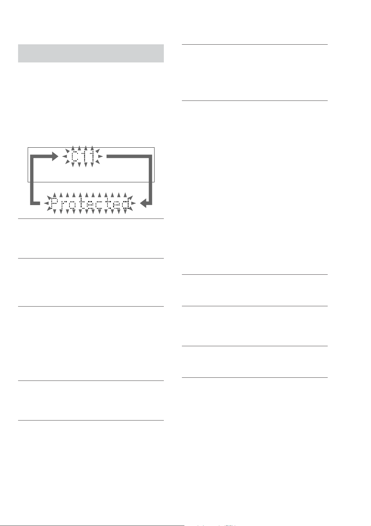
Self-diagnosis display
This system has a Self-diagnosis display
function to let you know if there is a system
malfunction. The display shows a code made
up of three or five letters and a message
alternately to show you the problem. To solve
the problem refer to the following list. If any
problem persists, consult your nearest Sony
dealer.
C11/Protected
The MD is protected against erasure.
cRemove the MD and slide the tab to close the
slot (see page 17).
C12/Cannot Copy
You tried to record a CD with a format that the
system does not support, such as a CD-ROM.
cRemove the disc and turn off the system once,
then turn it on again.
C41/Cannot Copy
The sound source is a copy of a commercially
available music software or CD-R.
cThe Serial Copy Management System prevents
making a digital copy (see page 64). In addition,
you cannot copy from a CD-R.
C71/Check OPT-IN
No component is connected to the DIGITAL
OPTICAL IN jack, or you tried to record from the
digital component which is not connected
correctly.
cConnect the optional digital component correctly
to the DIGITAL OPTICAL IN jack using the
digital optical cable (not supplied) (see page 53).
The power of the connected component is not
turned on.
cCheck if the power of the connected digital
component is on. Refer to the operating
instructions supplied with the component.
The digital optical cable is disconnected, or the
power of the connected component is turned off
while recording the digital audio from the
component connected to the DIGITAL OPTICAL
IN jack.
cConnect the digital optical cable, or turn on the
power of the connected component.
E0001/MEMORY NG
The component has internal problem.
cConsult your nearest Sony dealer.
C13/REC Error
Recording could not be performed properly.
cMove the system to a stable place, and start
recording over from the beginning.
The MD is dirty or scratched, or the MD does not
meet the standards.
cReplace the MD and start recording over from
the beginning.
C13/Read Error
The MD deck cannot read the disc information
properly.
cRemove the MD once, then insert it again.
C14/TOC Error
The MD deck cannot read the disc information
properly.
cReplace the MD.
cErase all the recorded contents of the MD using
the All Erase Function (see page 34).
E0101/LASER NG
There is a problem with the laser pickup.
cThe laser pickup may be damaged. Consult your
nearest Sony dealer.
E0201/LOADING NG
There is a problem with the loading.
cConsult your nearest Sony dealer.
4

HCD-CP505
Messages
One of the following messages may appear or
flash in the display during operation.
MD
Assign None
All the tracks on an MD are registered into groups.
Auto Cut
The MD deck is pausing the recording because
silence continued for 30 seconds or more during
digital recording (see page 25).
Blank Disc
The inserted recordable MD is new, or all tracks on
the MD have been erased.
Cannot Edit
•A pre-mastered MD is in the deck.
• You tried to edit in Program or Shuffle Play
mode.
• The track is recorded in MDLP mode.
Cannot REC
•A pre-mastered MD is in the deck.
• The function is switched to MD.
Cannot SYNC!
• There is no disc in the MD deck, or the MD is
protected against erasure (see page 17).
• There is no time remaining on the MD.
Complete!
The editing operation of the MD is completed.
Disc Full!
There is no time remaining on the MD.
Incomplete!
Adjustment of the recording level after recording
or Fade-in and Fade-out procedures have failed
since the system was either subject to vibration or
there is a damaged or dirty disc in the tray.
Initialize
The power was off for a long time, so the system is
initializing itself.
Name Full
There is no more space to store track, disc or group
titles.
No Change
While attempting to change the recording level
after recording, you pressed ENTER/YES on the
remote without actually changing the recording
level, so no change was made.
No Disc
There is no disc in the MD deck.
OVER
You have reached the end of the MD while turning
m/M clockwise (or pressing M on the
remote) during playback or playing pause.
Push STOP!
You pressed PLAY MODE during play.
—Rehearsal—
The MD is playing the specified point for
confirmation during the A-B Erase Function and
the Divide Function (pages 34 and 36).
Retry
A reading failure has occurred, and the system is
trying to read the data again.
Eject
The MD deck is ejecting the MD.
Group Full!
An attempt was made to create a new group in
excess of the maximum number of groups, or there
are insufficient characters for updating the group
management information.
Impossible
• You tried to make an impossible editing
operation.
• You cannot combine or erase the tracks due to
the system limitations of MDs.
S.F Edit!
You attempted to perform another operation while
in S.F Edit (changing the recording level after
recording, Fade-in, Fade-out) mode.
S.F Edit NOW
You pressed ?/1 while in S.F Edit (changing the
recording level after recording, Fade-in, Fade-out)
mode.
continued
5

HCD-CP505
Self-diagnosis display (continued)
Smart Space
The signal was input again after silence continued
for 3 or more but less than 30 seconds during
digital recording, and the silence was cut to 3
seconds.
Step Full!
You tried to program 26 or more tracks (steps).
TOC Reading
The MD deck is reading the TOC information of
the MD.
TOC Writing
The MD deck is writing the information of
recorded or edited contents.
Track End
You have reached the end of the track while
adjusting the dividing point during the Divide
Function.
CD
No Disc
There is no CD in the player.
OVER
You have reached the end of the CD while turning
m/M clockwise (or pressing M on the
remote) during play or pause.
Push STOP!
You pressed PLAY MODE during play.
Step Full!
You tried to program 26 or more tracks (steps).
TAPE
Cannot SYNC!
There is no tape in the tape deck, or the tab has
been removed from the cassette.
No Tab
You cannot record the tape because the tab has
been removed from the cassette.
Tr Protected
You attempted to erase a protected track.
No Tape
There is no tape in the tape deck.
6

HCD-CP505
Note 1: About “R”
As this unit has only a few buttons, some operations require the use of remote commander (RM-SCP500/provided with unit) buttons. These
operations are indicated as “R” in this manual.
Example: MENU/NO “R” ...Press the MENU/NO button of the remote commander.
Note 2: Incorrect operations may be performed if the test mode is not entered properly.
In this case, press the ?/1 button to turn the power off, and retry to enter the test mode.
How to Operate the Self-diagnostics Function (Error History Display Mode)
Note: Use the self-diagnostics function in the "error history display mode" of the test mode. The least required procedure is described
below. Do not enter any other modes by mistake. If you have entered any other modes accidentally, press the MENU/NO “R”
button to exit the mode.
1. Press the ?/1 button to turn on the power.
2. Press the FUNCTION button to select the “MD” function.
3. While pressing the x button and the ENTER/START button at the same time, press the FUNCTION button.
4. Press the > “R” button to display “[Service]”. Then press the ENTER/YES “R” button.
5. Press the > “R” button to display “Err Display”.
6. Press the ENTER/YES “R” button to enter the error history display mode and “op rec tm” appears.
7. Select the desired contents that you want to display or to execute using the . “R” button or the > “R” button.
8. Press the REC MODE button to display or to execute the selected contents.
9. Press the REC MODE button again to return to step 7.
10. Press the MENU/NO “R” button. The message “Err Display” appears and you exit the error history mode.
11. Press the REPEAT button twice to exit the test mode.
12. Press the ?/1 button to turn off the power.
7
HCD-CP505
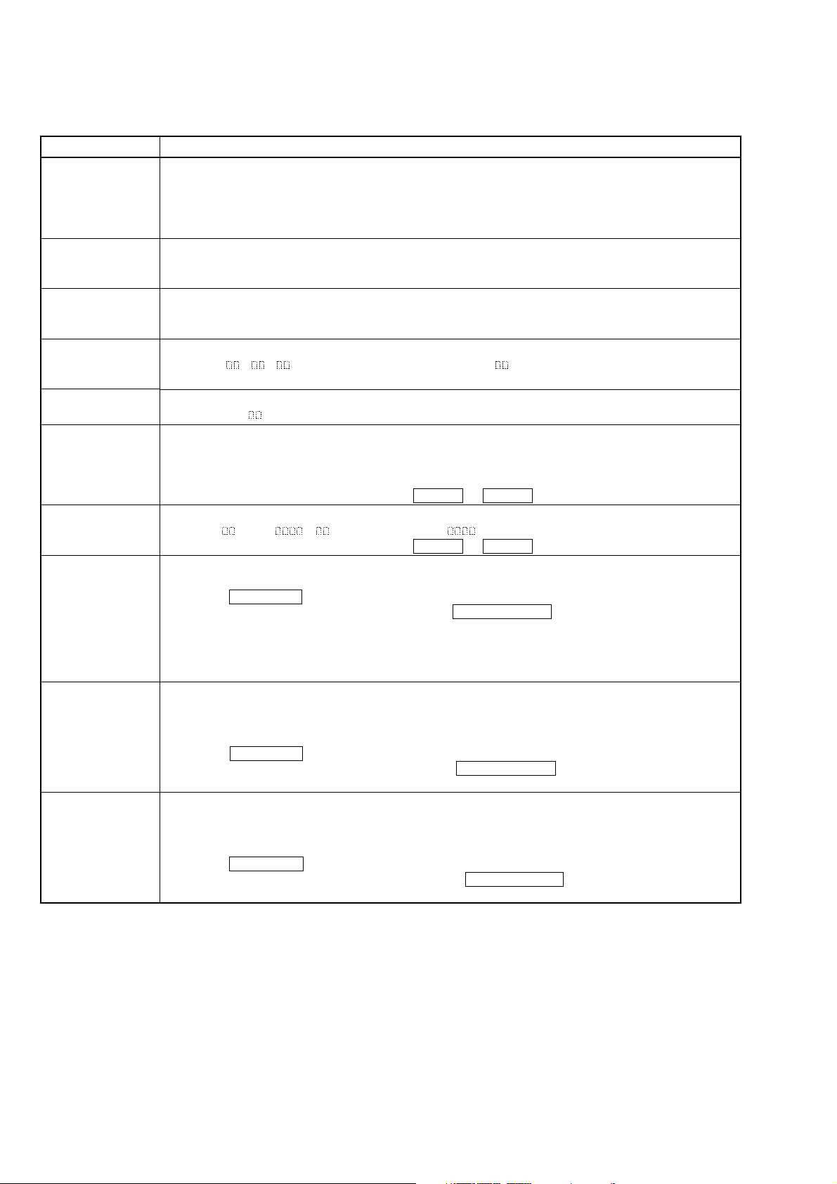
Items of Error History Mode Items and Contents
Selecting the Test Mode
Display
op rec tm
op play tm
spdl rp tm
retry err
total err
err history
retry adrs
er refresh
op change
spdl change
History
Displays the accumulated recording time.
When the accumulated recording time is more than 1 minute, displays the hour and minute
When less than 1 minute, displays “Under 1 min”
The display time indicates the time when the laser is set to high power more, which is about 1/4 of the actual
recording time.
Displays the accumulated playback time.
When the accumulated playback time is more than 1 minute, displays the hour and minute
When less than 1 minute, displays “Under 1 min”
Displays the accumulated rotating time of the spindle motor.
When the accumulated rotating time is more than 1 minute, displays the hour and minute
When less than 1 minute, displays “Under 1 min”
Displays the accumulated number of retry errors during recording and playback
Displays “r
This is displayed in hexadecimal from 00 to FF.
Displays the total number of errors
Displays “total ”. This is displayed in hexadecimal from 00 to FF.
Displays the past ten errors.
Displays “0x ErrCd@@”.
X is the history number. The younger the number, the more recent is the history (00 is the latest). @@ is the
error code.
Select the error history number by pressing the . “R” or > “R” button.
Displays the past five retry addresses.
Displays “
Select the error history number by pressing the . “R” or > “R” button.
Mode for erasing the error and retry address histories
Procedure
1. Press the REC MODE button when displayed as “er refresh”.
2. When the display changes to “er refresh?”, press the ENTER/YES “R” button
When “Complete!!” is displayed, it means erasure has completed.
Be sure to check the following after executing this mode.
*Data has been erased.
*Perform recording and playback, and check that the mechanism is normal.
Mode for erasing the accumulated time of op rec tm, op play tm.
Use these histories as a guide line for the time of replacement of the optical pick-up. If the optical pick-up
has been replaced, perform this procedure and erase the past history.
Procedure
1. Press the REC MODE button when displayed as “op change”.
2. When the display changes to “op change?”, press the ENTER/YES “R” button.
When “Complete!!” is displayed, it means erasure has completed.
Mode for erasing the accumulated spdl rp tm time
Use these histories as the guide line for the time of replacement of the spindle motor. If the spindle motor has
been replaced, perform this procedure and erase the past history.
Procedure
1. Press the REC MODE button when displayed as “spdl change”
2. When the display changes to “spdl change?”, press the ENTER/YES “R” button.
When “Complete!!” is displayed, it means erasure has completed.
p ”. is the number of errors during recording. is the number of errors during playback.
ADRS ”, is the history number, is the cluster with the retry error.
8
Table of Error Codes
Error Code Description
10
Could not perform loading
HCD-CP505
11
12
20
21
22
23
24
30
31
40
41
42
43
50
51
The changer error occurred
Loading switches combined incorrectly
Timed out without reading the top of PTOC
Could read top of PTOC, but detected error
Timed out without accessing UTOC
Timed out without reading UTOC
Error in UTOC
Could not start playback
Error in sector
A cause of retry occurred during normal recording
Retried due to DRAM overflow
Retry occurred during TOC writing
Retry aborted during S.F editing
Other than access processing, and could not read address.
Focus NG occurred and overran.
9
HCD-CP505
C
SECTION 1
SERVICING NOTE
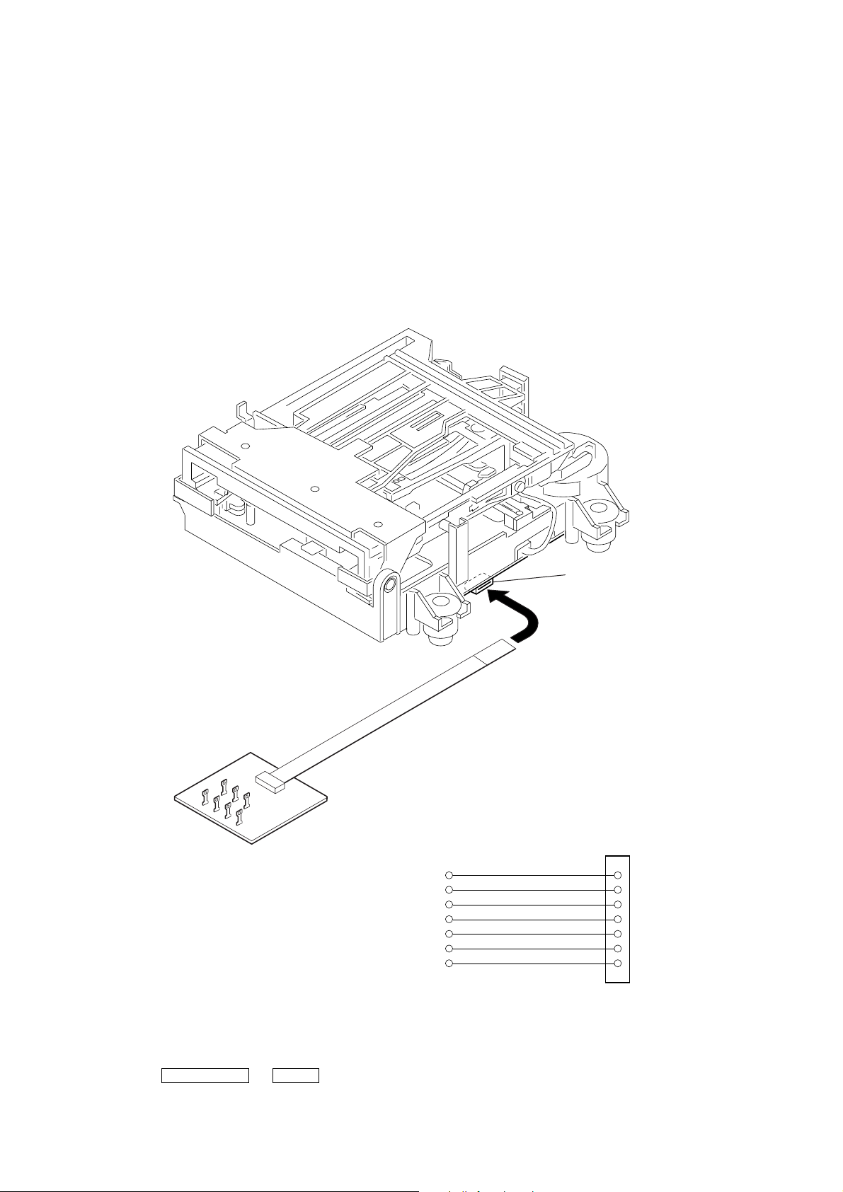
Jig For Checking BD (MD) Board Waveform
The special jig (J-2501-196-A) is useful for checking the waveform of the BD board. The names of terminals and the checking items to be
performed are shown as follows.
GND : Ground
I+3V : For measuring Iop (Check the deterioration of the optical pick-up laser)
Iop : For measuring Iop (Check the deterioration of the optical pick-up laser)
TE : TRK error signal (Traverse adjustment)
VC : Reference level for checking the signal
RF : RF signal (Check jitter)
FE : Focus error signal
I+3V
GND
FE
RF
Iop
TE
VC
I+3V
Iop
GND
TE
FE
VC
RF
CN105
1
7
I+3V
Iop
GND
TE
FE
VC
RF
for MDM-7S2
• Disc Tray Lock
If the disc tray does not open and the message “LOCKED” appears,
press the two buttons of ENTER/START and Z DVD at the same
for 5 seconds or longer.
Then the lock is released, the message “UNLOCKED” appears for
2 seconds and the disc tray opens.
10
HCD-CP505
Iop DATA RECORDING AND DISPLAY WHEN OPTICAL PICK-UP AND NON-VOLATILE MEMORY (IC195 OF
BD BOARD) ARE REPLACED
The Iop value labeled on the optical pick-up can be stored in the non-volatile memory. By storing the value, it will eliminate the need to look
at the value on the label of the optical pick-up. When replacing the optical pick-up or non-volatile memory (IC195 of BD (MD) board), store
the Iop value on the optical pick-up according to the following procedure.
Record Precedure:
1. Press the ?/1 button to turn on the power.
2. Press the FUNCTION button to select the “MD” function.
3. While pressing the x button and the ENTER/START button at the same time, press the FUNCTION button.
4. Press the > “R” button to display “[Service]”. Then press the ENTER/YES “R” button.
5. Press the > “R” button to display “Iop Write” (C05) and press the ENTER/YES “R” button.
6. The display becomes “Ref=@@@.@” (@ is an arbitrary number) and the numbers which can be changed will blink.
7. Input the Iop value written on the optical pick-up.
To select the number : Press the . “R” button or the > “R” button.
To select the digit : Press the REC MODE button.
8. When the ENTER/YES “R” button is pressed, the display becomes “Measu=@@@.@” (@ is an arbitrary number).
9. As the adjustment results are stored for the 6 value. Leave it as it is and press the ENTER/YES “R” button.
10. “Complete!” will be displayed momentarily. The value will be stored in the non-volatile memory and the display will become “Iop
Write” (C05).
11. Press the REPEAT “R” button to exit the mode.
12. Press the ?/1 button to turn off the power.
Display Precedure:
1. Press the ?/1 button to turn on the power.
2. Press the FUNCTION button to select the “MD” function.
3. While pressing the x button and the ENTER/START button at the same time, press the FUNCTION button.
4. Press the > “R” button to display “[Service]”. Then press the ENTER/YES “R” button.
5. Press the > “R” button to display “Iop Read” (C26) and press the ENTER/YES “R” button.
6. “@@.@/##.#” is displayed and the recorded contents are displayed.
@@.@ : indicates the Iop value labeled on the optical pick-up
##.# : indicates the Iop value after adjustment
7. To end, press the MENU/NO “R” button to display “Iop Read” (C26). Then press the REPEAT “R” button.
8. Press the ?/1 button to turn off the power.
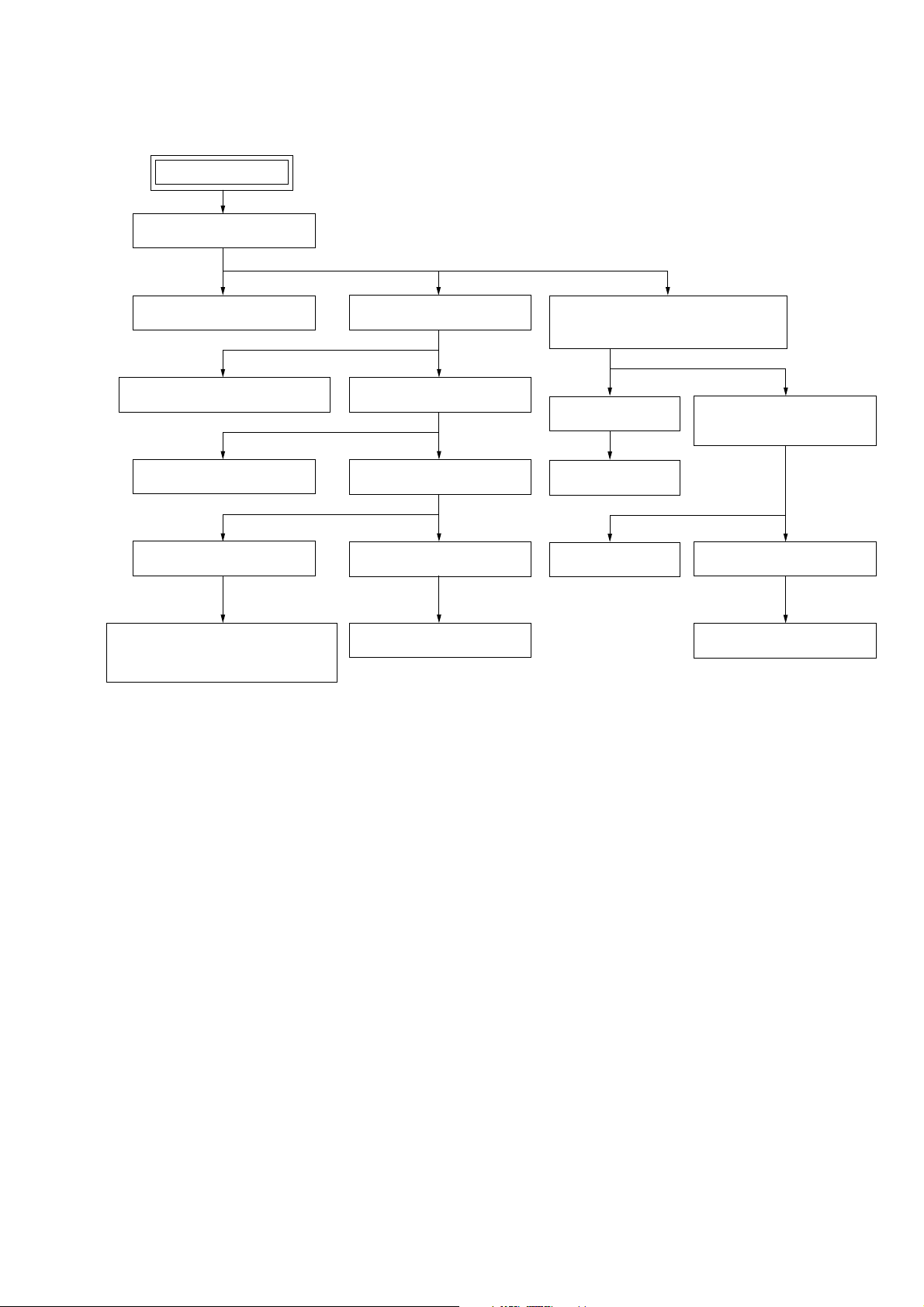
Checks Prior to Parts Replacement and Adjustments in MD
Before performing repairs, perform the following checks to determine the faulty locations up to a certain extent.
Details of the procedures are described in “Section 5 Electrical Adjustments”.
Laser power check
(6-2 : See page 34)
Auto check
(6-4 : See page 35)
Temperature
compensation
offset check
(6-1 : See page 34)
Criteria for Determination
(Unsatisfactory if specified value is not satisfied)
• 0.93 mW power
Specified value : 0.84 to 0.92 mW (KMS-262A)
0.90 to 0.96 mW (KMS-262E)
• 8.65 mW power
Specified value : 8.1 to 8.7 mW (KMS-262A)
8.4 to 8.9 mW (KMS-262E)
• Iop (at 8.65 mW)
Labeled on the optical pick-up
Iop value ± 10mA
• Unsatisfactory if displayed as “NG : XXXX”NG
(XXXX are arbitrary numbers)
• Unsatisfactory if displayed as “T=@@ (##) [NG]”
NG
(@@, ## are both arbitrary numbers)
• Clean the optical pick-up
• Adjust again
• Replace the optical pick-up
• Replace the optical pick-up
• Replace the optical pick-up
• Check for disconnection of the circuits around
D101 (BD (MD) board)
• Check the signals around IC101, IC151, CN102,
CN103 (BD (MD) board)
Measure if unsatisfactory
Note:
The criteria for determination above is intended merely to determine if satisfactory or not, and does not serve as the specified value for adjustments.
When performing adjustments, use the specified values for adjustments.
11
HCD-CP505
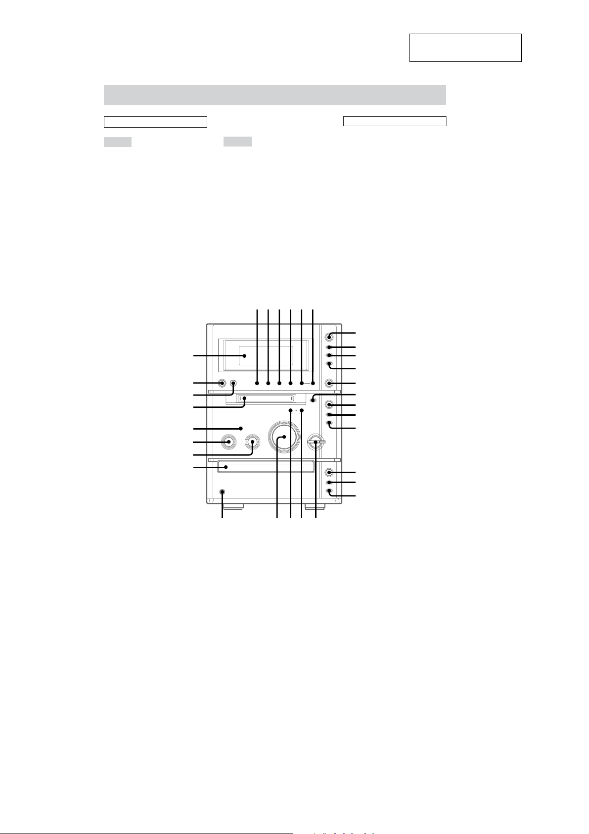
Main unit
SECTION 2
GENERAL
This section is extracted
from instruction manual.
ALPHABETICAL ORDER
A – G
BASS wh (47)
CD NX qh (9, 10, 22)
DIRECTION 2 (21, 44, 45–47)
Disc tray wf (9)
Display window ea
DSG wj (47)
ENTER/START 6 (20, 21, 45,
46)
FM MODE 3 (43)
FUNCTION 1 (9, 13, 16, 19,
21–23, 25, 44, 47, 54)
GROUP ON/OFF wa (15, 16, 18–
20, 29–32)
GROUP SKIP w; (16, 19, 20, 29,
30, 32)
ea
e;
wl
wk
wj
wh
wg
wf
M – V
MD slot wk (13)
MD NX qd (13, 14, 16, 21)
PHONES jack wd
PLAY MODE 2 (9–11, 13, 15,
28)
REC MODE 4 (20–22, 26)
Remote sensor wl
REPEAT 3 (10, 14)
SYNCHRO 5 (20, 21, 45, 46)
TAPE nN 7 (44–46)
TREBLE wg (47)
TUNER BAND qa (41–43)
TUNING +/– ql (41–43)
TUNING MODE 2 (41–43)
VOLUME ws
123456
?/1
x
+–+
–
BUTTON DESCRIPTIONS
?/1 (power) e;
m/M ql
l/L ql
TAPE
X 9
x 8
zREC 0
MD
Z qs
x qf
zREC qg
CD
Z qk
x qj
nN
7
x
8
X
z
9
0
qa
z
lm
ML
qs
NX
qd
x
qf
qg
–
+
NX
qh
x
qj
Z
Z
qk
qlw;wawswd
12
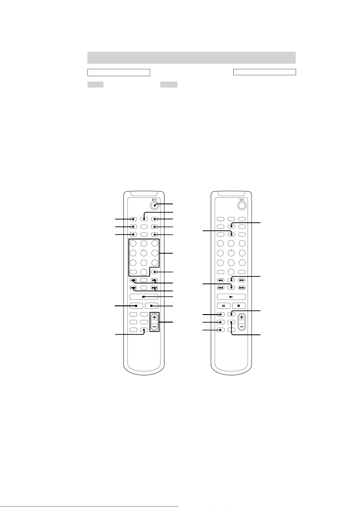
Remote Control
HCD-CP505
ALPHABETICAL ORDER
A – F M – V
BASS/TRE 4 (47)
CD wd (10–13)
CLEAR 7 (10, 15, 30, 43)
CLOCK/TIMER SELECT 2
(49, 50)
CLOCK/TIMER SET 3 (8, 48,
49)
CURSOR T/t 8 (8, 12, 29,
30)
DISPLAY wg (11, 15, 22, 44, 50–
52)
DSG qd (47)
ENTER/YES 5 (8, 10, 12, 13,
15, 22–26, 28–43, 48–50)
FUNCTION ws (9, 13, 16, 19,
21–23, 25, 44, 47, 54)
MD wf (15, 24, 25, 28, 29, 31–
37, 39, 40)
MENU/NO qg (12, 13, 23–26,
28, 30–41, 43)
NAME EDIT/SELECT wh
(11, 29, 43)
Numeric buttons 6 (10, 12, 14,
29, 42)
PLAY MODE qh (9–11, 13, 15,
28)
REPEAT qk (10, 14)
SCROLL ql (12, 30, 52)
SLEEP qj (48)
TAPE wa
TUNER BAND w; (41–43)
VOLUME +/– qs
qj
qh
qg
1
2
3
4
5
BUTTON DESCRIPTIONS
@/1 (power) 1
N 0
X qf
x qa
m/M 8
./> 9
qk
wh
qf
qd
6
7
8
9
0
qa
qs
wg
wf
wd
ws
ql
w;
wa
13

HCD-CP505
Setting the clock
1
Press ?/1 to turn on the system.
2
Press CLOCK/TIMER SET on the
remote.
3
Press . or > on the remote
repeatedly to set the hour.
4
Press ENTER/YES or CURSORt on
the remote.
5
Press . or > on the remote
repeatedly to set the minute.
6
Press ENTER/YES on the remote.
The clock starts working.
If you make a mistake
Press TCURSOR or CURSORt on the
remote repeatedly until the incorrect item
flashes, then set it again.
To adjust the clock
1
Press CLOCK/TIMER SET on the remote.
2
Press . or > on the remote to select
“CLOCK SET”, then press ENTER/YES on
the remote.
3
Do the same procedures as step 3 to 6 above.
14
• The equipment can be removed using the following procedure.
SET
TOP PANEL SECTION
HCD-CP505
SECTION 3
DISASSEMBLY
CASSETTE MECHANISM DECK
SWITCH BOARD, JACK BOARD
DIGITAL BOARD
BD(MD) BOARD
LOADING MOTOR ASSEMBLY(M103),
SPINDLE MOTOR ASSEMBLY(M101),
SLED MOTOR ASSEMBLY(M102)
MD
MINI DISC DEVICE (KMS-262E)
FRONT PANEL,
MECHANISM DECK BLOCK
MD MECHANISM DECK
(MDM-7S2C)
HOLDER SECTION
OVER WRITE HEAD (HR901)
BACK PANEL SECTION
(INCLUDING OPTICAL BOARD,
OPTICAL RETAINER BOARD)
MAIN BOARD
POWER BOARD
CAM (CDM55)
BASE UNIT (BU-30BBD61B)
CONTROL BOARD,
CD MECHANISM DECK
(CDM55G-30BBD61B)
OPTICAL PICK-UP
(BU-30B Assy)
15
HCD-CP505
)
)
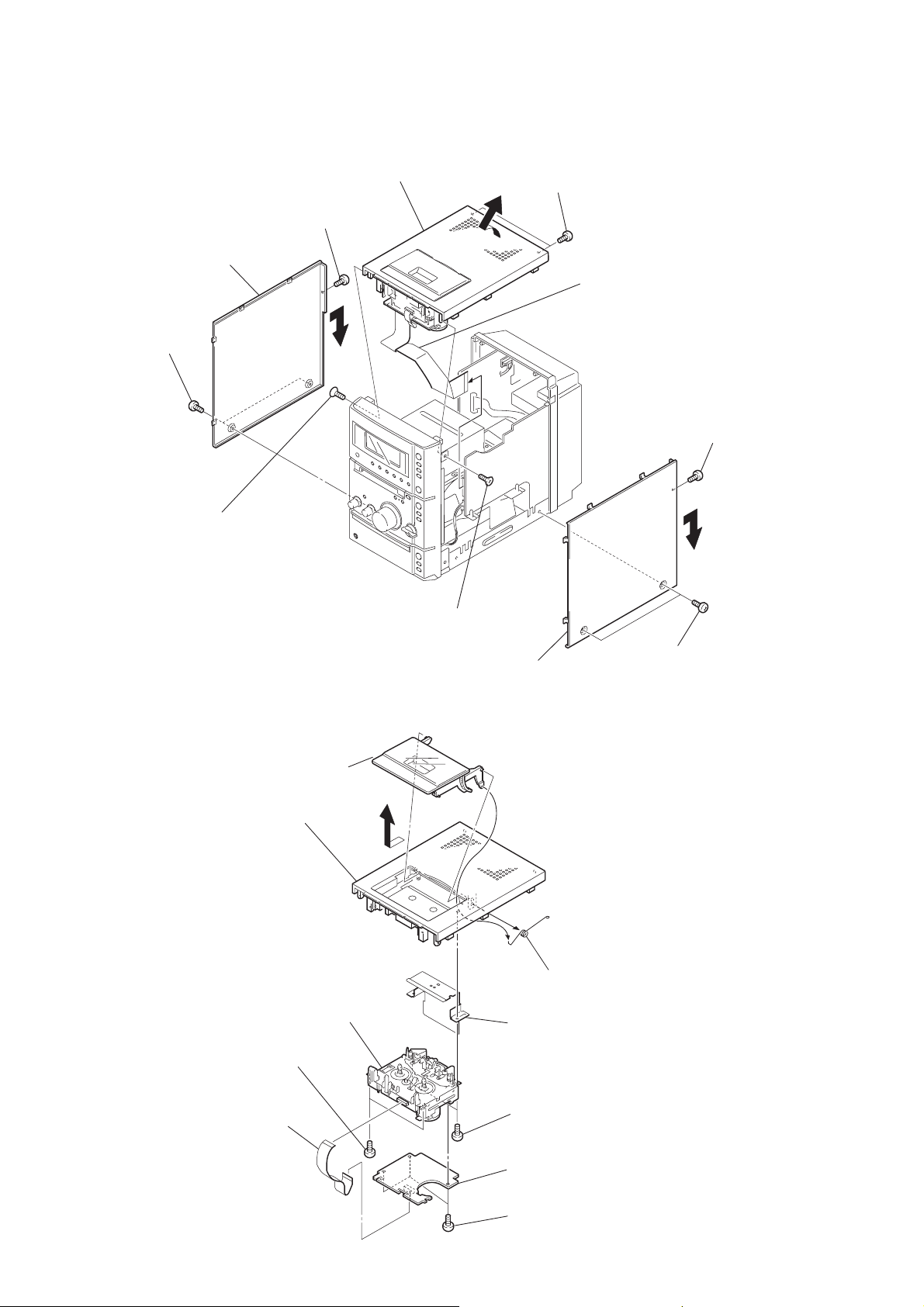
Note: Follow the disassembly procedure in the numerical order given.
3-1. Top Panel Section
0
Remove the top cover in the
direction of the arrow.
2
screw
×
8)
3
Remove the panel side (L) in the
direction of the arrow.
1
two screws
(case 3 TP 2)
(BTP 3
7
two screws
(BTP 3
×
8)
qa
wire (flat type) (17 core)
(CN301 )
5
screw
(BTP 3
×
8)
8
screw
×
(KTP 3
3-2. Cassette Mechanism Deck
qs
cassette holder
8)
top panel
qa
9
screw
×
(KTP 3
8)
6
Remove the panel side (R) in the
direction of the arrow.
9
8
4
two screws
(case 3 TP 2
16
6
cassette mechanism deck
4
two screws (BVTP 3 × 8)
wire (flat type) (8 core)
1
(CN302 )
0
spring
7
shield case (tc)
5
two screws (BVTP 3 × 8)
3
TC board
2
three screws (BVTT 2.6 × 5
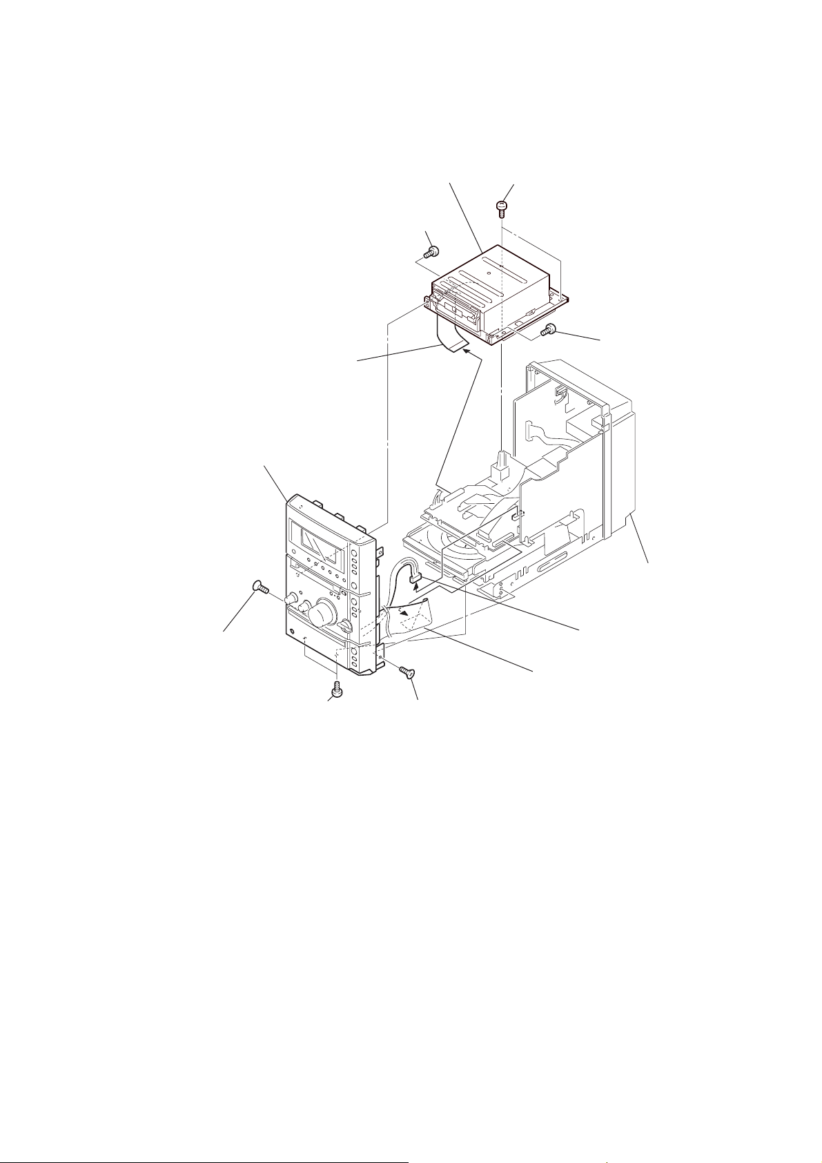
3-3. Front Panel, MD Mechanism Deck Block
)
5
MD mechanism deck block
2
screw (BVTP 3 × 8)
4
wire (flat type) (27 core)
(CN608 )
1
two screws
(BVTP 3
HCD-CP505
×
8)
3
screw (BVTP 3 × 8
qa
9
screw (KTP 3 × 8)
front panel section
0
two screws (BVTP 3 × 8)
8
screw (KTP 3 × 8)
chassis section
6
connector cable
(CNP603 )
7
wire (flat type) (27 core)
(CN604 )
17
HCD-CP505
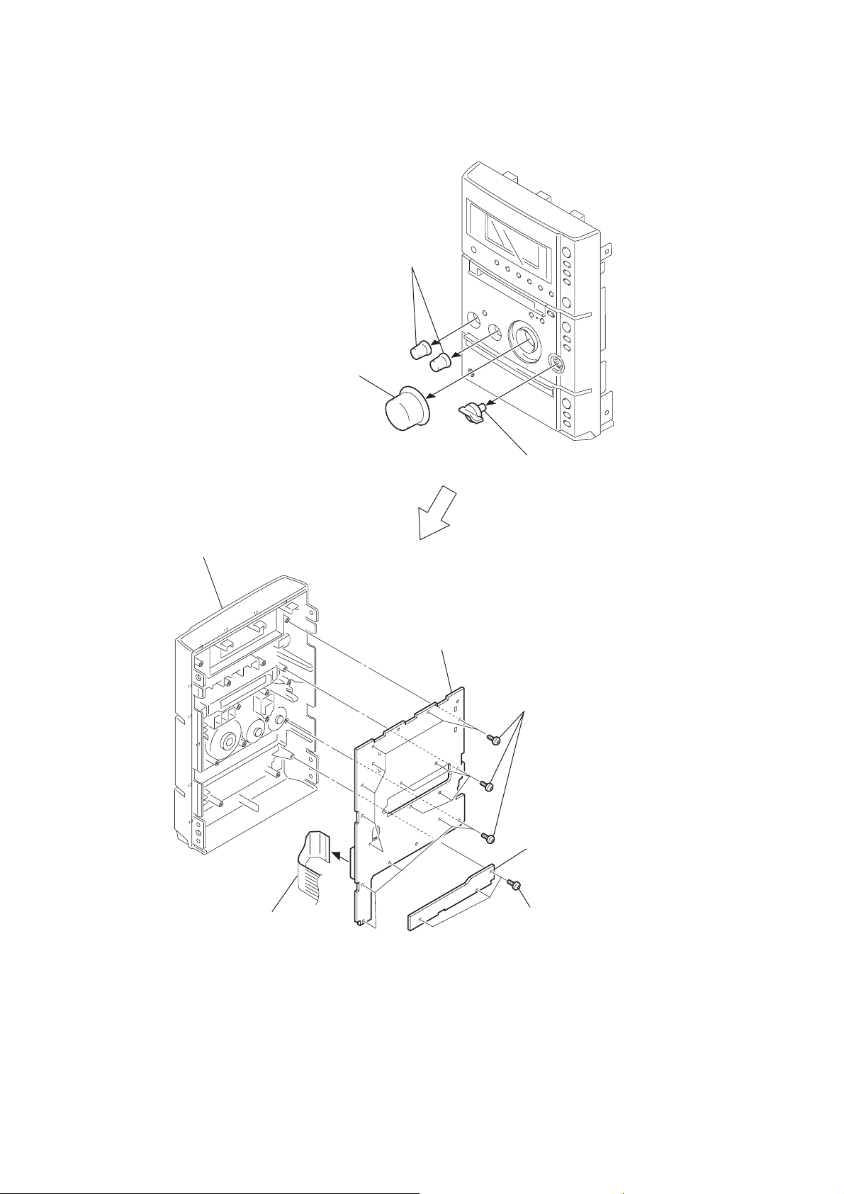
3-4. SWITCH Board, JACK Board
1
volume knob
3
two bass knobs
front panel
8
SWITCH board
2
tuning knob
6
seventeen screws
(BVTP 2.6
5
JACK board
×
8)
18
7
wire (flat type) (27 core)
(CN802 )
4
three screws
(BVTP 2.6
×
8)
3-5. Back Panel Section (Including OPTICAL Board, OPTICAL RETAINER Board)
)
7
OPTICAL board
0
back panel
6
OPTICAL RETAINER board
5
two screws
(BVTP 3 × 8)
1
connector cable
(CN602 )
HCD-CP505
3
four screws
(BTP 3 × 8)
4
three screws
(BTP 3 × 8)
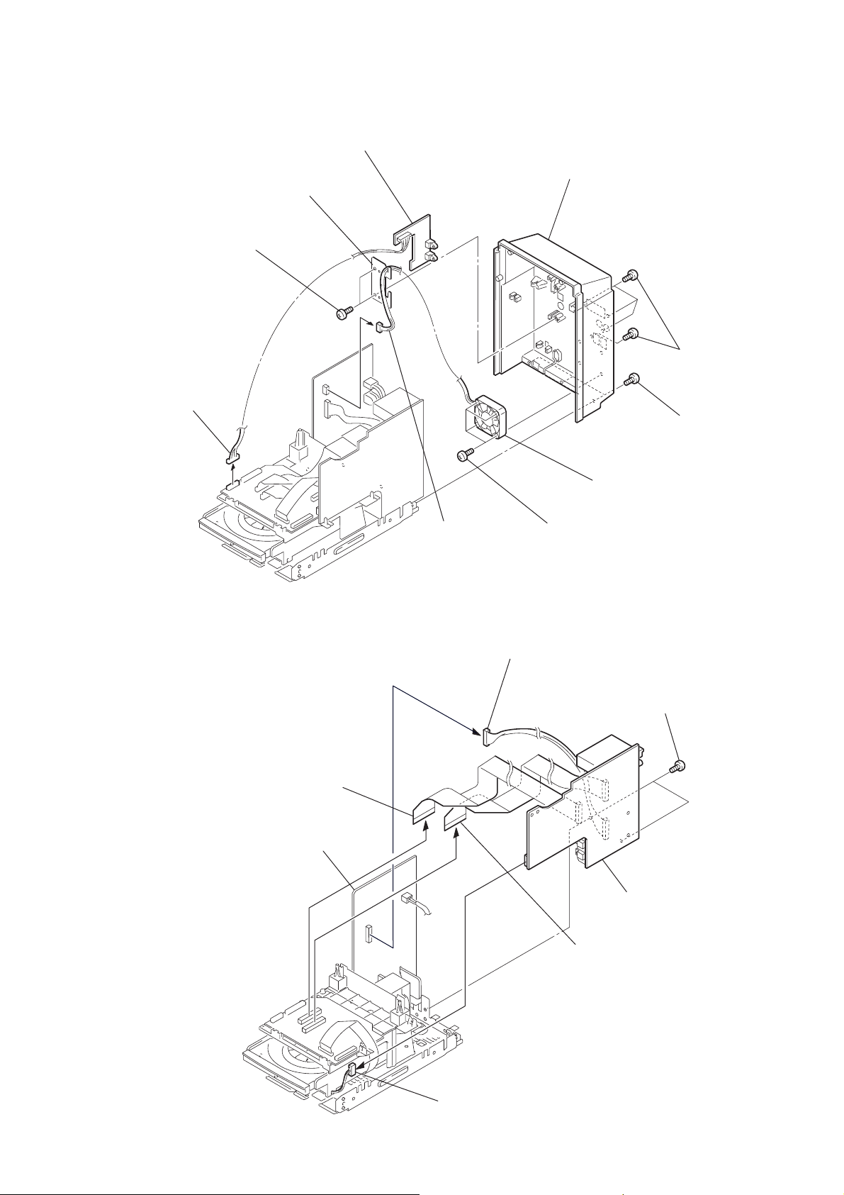
3-6. MAIN Board
1
wire (flat type) (25 core)
(CN606 )
POWER board
2
connector cable
(CN904 )
4
connector cable
(CN902 )
8
four screws
(BVTP 3 × 10)
9
D.C. fan
5
two screws
(BVTP 3
×
8
3
connector cable
(CN304 )
6
MAIN board
2
wire (flat type) (25 core)
(CN605 )
19
HCD-CP505
)
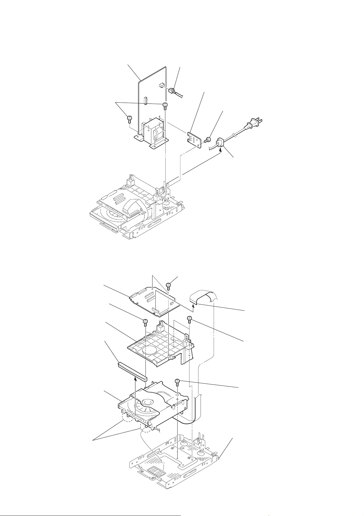
3-7. POWER Board
5
four screws
(BVTT 4
6
POWER board
×
8)
1
connector cable
(CN901 )
4
POWER RETAINER board
3
screw
(BVTP 3
2
cord stopper
×
8)
3-8. CONTROL Board, CD Mechanism Deck (CDM55G-30BBD61B)
2
3
CONTROL board
5
two screws
(BV 2.6 × 8)
6
cd bracket
7
0
CD mechanism deck
(CDM55G-30BBD61B)
two screws
(BVTP 3
cd lid
×
8)
1
wire (flat type) (23 core
(CN601 )
4
8
screw
(BVTP 3 × 8)
two screws
(BVTP 3 × 8)
20
9
Remove the two claws.
chassis section
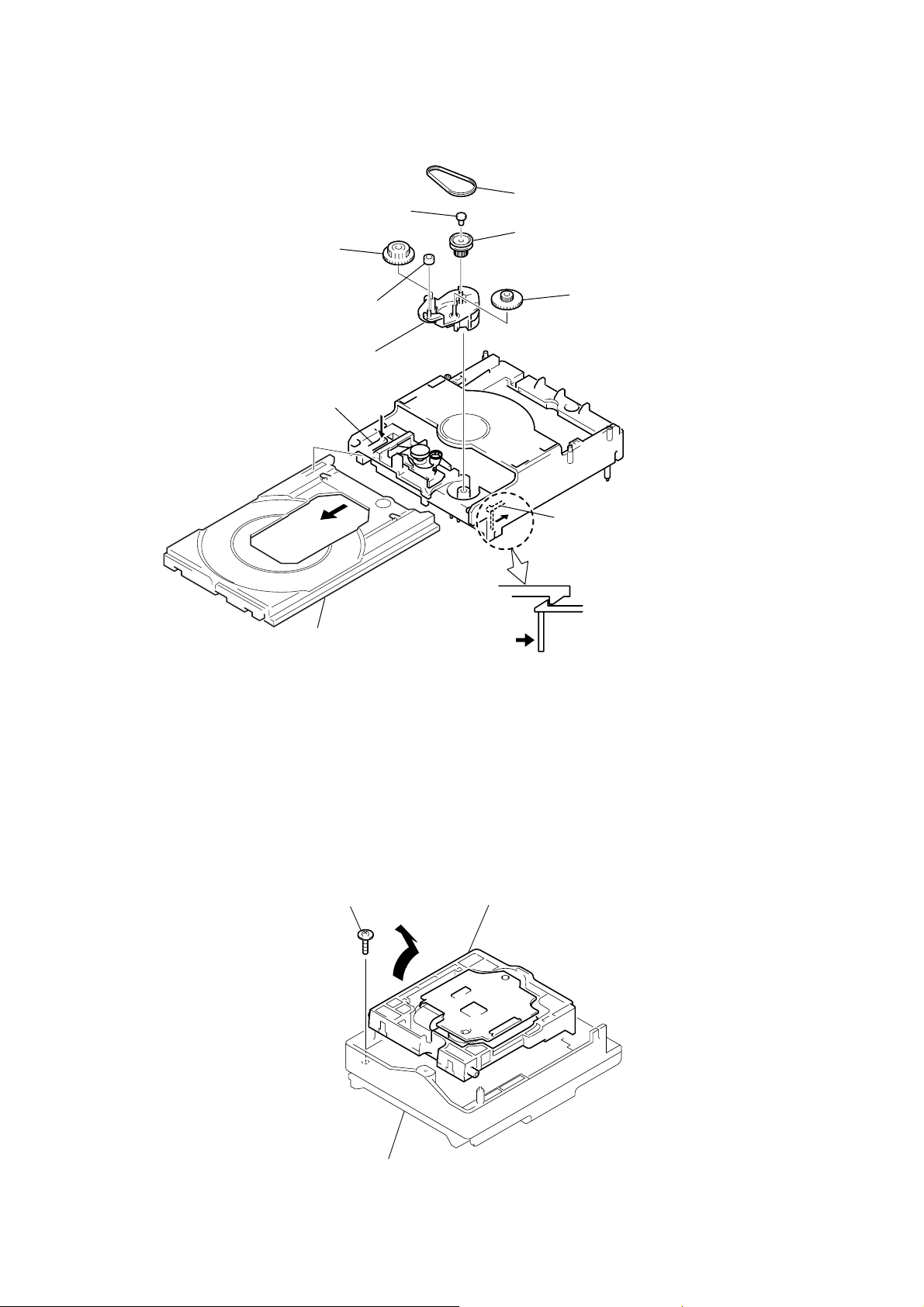
3-9. Cam (CDM55)
)
2
Push the claw in the
direction of the arrow
8
gear (B)
5
spacer (55)
7
roller
q;
cam (CDM55)
C
.
C
4
belt (CDM55)
6
pulley (LDG)
9
gear (A)
HCD-CP505
A
3
Pull out the tray.
3-10. Base Unit (BU-30BBD61B)
1
floating screw
(+PTPWH M2.6)
A
1
B
B
2
Remove the base unit (BU-30BBD61B
in the direction of the arrow A.
Pull out the tray in the direction of the arrow A.
While pushing this claw in the direction of the arrow
release the lock.
Release the lock.
B
,
3
chassis (55D)
21
HCD-CP505
s
)
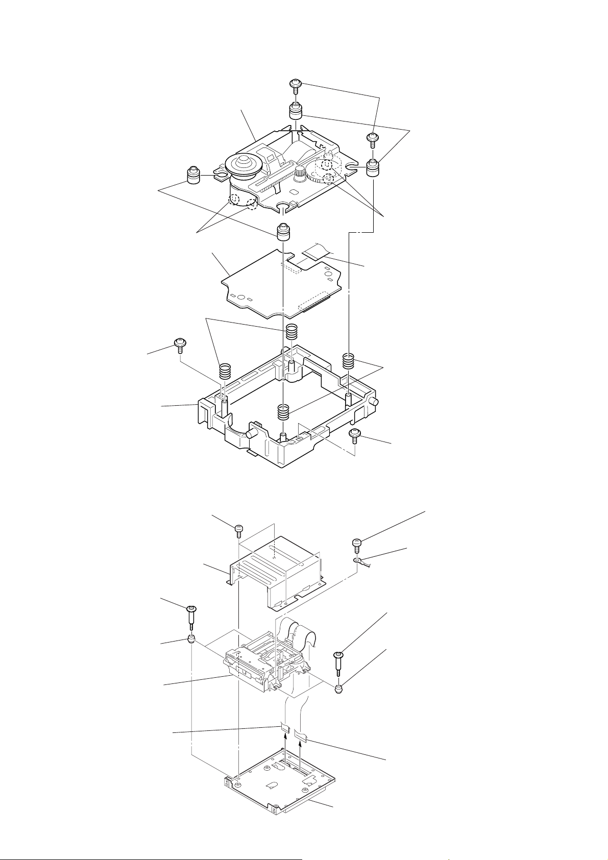
3-11. Optical Pick-Up (BU-30B Assy)
8
two insulators
0
Remove the two solderings
qs
BD (CD) board
6
two compression springs
qd
BU-30B assy
4
two floating screws
(+PTPWH M2.6)
9
two insulators
qa
Remove the two soldering
1
wire (flat type) (16 core)
3
two floating screws
(+PTPWH M2.6)
5
bu holder (BU-30)
3-12. MD Mechanism Deck (MDM-7S2C)
1
four screws
(BVTP 3 × 8)
2
MD cover (upper)
7
two step screws
(BVTTWH M 3)
7
two compression springs
2
two floating screws
(+PTPWH M2.6)
5
screw
(BVTT 2
6
lead (with connector
8
two step screws
(BVTTWH M 3)
×
4)
22
9
two insulators
qa
MD mechanism deck
(MDM-7S2C)
3
wire (flat type) (17 core)
(CN703 )
0
two insulators
4
wire (flat type) (27 core)
(CN702)
MD cover (lower) section
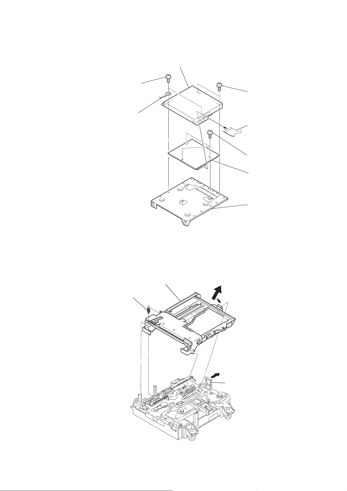
3-13. DIGITAL Board
)
k
4
2
two screws
(BVTP 3
lead (with connector)
×
8)
5
MD cover (lower)
3
two screws
(BVTP 3
1
wire (flat type) (25 core
6
three screws
(BVTP 3
7
DIGITAL board
×
8)
×
8)
HCD-CP505
3-14. Holder Section
1
tension spring (holder)
3
holder section
8
MD bracket
2
hoo
23
HCD-CP505
y
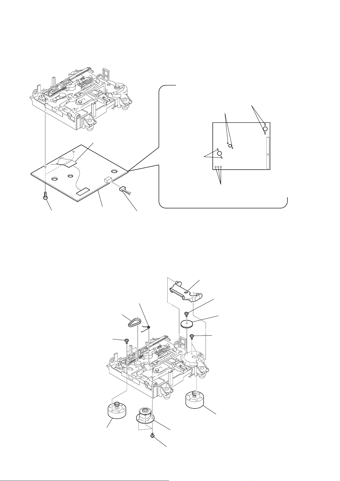
3-15. BD (MD) Board
6
flexible board
(CN101)
1
Remove the
2
Remove the
two solderings (spindle motor)
3
Remove the
two solderings
(loading motor)
two solderings (sled motor)
M103
S102
M102
M101
4
Remove the
three solderings
8
5
two screws
(+B (P) TRI 2
×
6 CZN)
BD (MD) board
7
connector cable (CN104)
3-16. Loading Motor Assembly (M103), Spindle Motor Assembly (M101), Sled Motor Assembly (M102)
1
lever (head)
8
3
torsion spring (spindle)
2
belt (loading)
4
two screws
(PWH 1.7 × 2.5)
tapping screw
(M1.7 )
9
gear (sa)
0
two screws
(PWH 1.7 × 2.5)
24
5
loading motor assembly
(M103)
7
spindle motor assembly
(M101)
6
three tapping screws
(M1.7 )
qa
sled motor assembl
(M102)
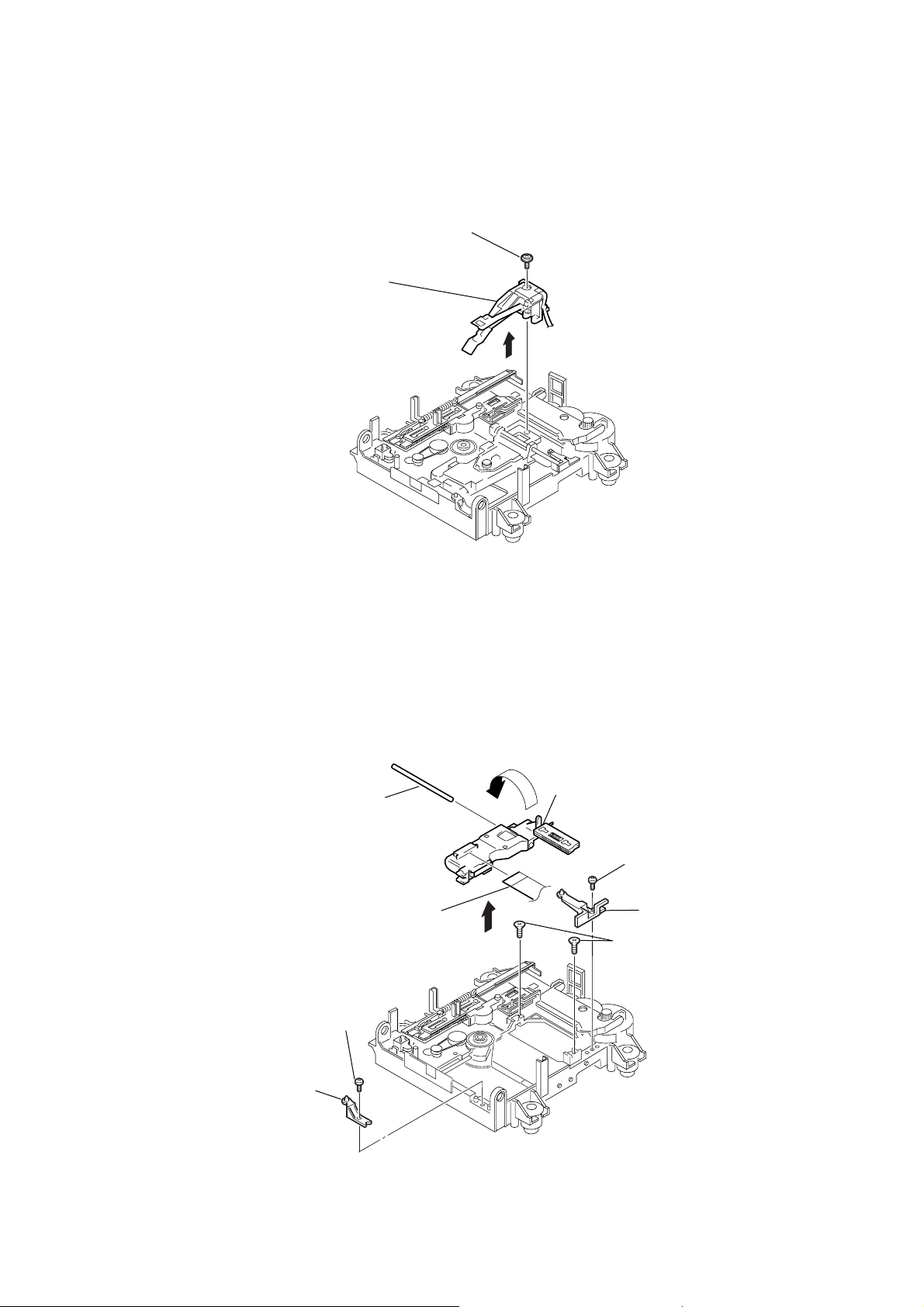
3-17. Over Wright Head (HR901)
)
2
over write head
(HR901)
1
screw (P 1.7 × 6)
HCD-CP505
3-18. Mini Disc Device (KMS-262E)
6
main shaft
7
1
screw
(+B (P) TRI 2
2
base (BU-D)
×
6 CZN)
flexible board
8
Mini disc device (KMS-262E)
3
screw
(+B (P) TRI 2
4
base (BU-A)
5
two screws
(+KTP 2
×
6 CZN
×
6)
25
HCD-CP505
SECTION 4
TEST MODE
Note 1: About “R”
As this unit has only a few buttons, some operations require the use of remote commander (RM-SCP500/provided with unit) buttons. These
operations are indicated as “R” in this manual.
Example: MENU/NO “R” ...Press the MENU/NO button of the remote commander.
Note 2: Incorrect operations may be performed if the test mode is not entered properly.
In this case, press the ?/1 button to turn the power off, and retry to enter the test mode.
1. Cold Reset
•The cold reset clears all data including preset data stored in the RAM to initial conditions. Execute this mode when returning the set to
the customers.
Procedure:
1. Press ?/1 button to turn the power on.
2. Press three buttons x , ENTER/START and ?/1 simultaneously.
3. When this button is operated, all of the settings other that CD are reset. Then the POWER is turned off and the watch display appears.
2. Panel Test Mode
•This mode is used to check the software version, LCD, LED and keyboard.
Procedure:
1. Press the ?/1 button to turn on the power.
2. Press the FUNCTION button to enter mode other than “TUNER”.
3. Press three bottons x (TAPE), ENTER/START and x (CD) simultaneously.
4. LEDs and LCD are all turned on.
2-1. Version check
1. When entering the software version display mode, press REPEAT button. The model name (“CP505MD”) and destination are
displayed, and the MD , CD and TAPE segments flash.
2. Each time REPEAT button is pressed, the display changes “MC, GC, CD, CDD, CDMA, CDMB, BDA, BDB, ST, TA, TM, TC and
MD” (returns to MC) in this order, and returns to the top of the version display.
3. When REC MODE button is pressed while the version numbers are being displayed, year, month and day of the software creation
appear. When REC MODE button is pressed again, the display returns to the software version display. When REPEAT button is
pressed while year, month and day of the software creation are being displayed, the year, month and day of creation of the software
versions are displayed in the same order of version display.
2-2. Key check
1. Press PLAY MODE button, and the key check mode is activated. In the key check mode, the LCD displays “K 0 J 0 V 0”. Each time
a button is pressed, “K 0” value increases. However, once a button is pressed, it is no longer taken into account. It is end at
“K24J 0V 0”.
A turn of BASS knob or TREBLE knob changes the value of “J” between 0 and 9. If it turns to the right, a value will increase, and
if it turns to the left, a value will decrease. A turn of VOLUME knob changes value of “V” between 0 and 9. If it turns to the right,
a value will increase, and if it turns to the left, a value will decrease.
2. To exit from this mode, press three buttons in the same manner as step 3, or disconnect the power cord.
3. Common Test Mode
Procedure:
1. Press ?/1 button to turn the power on.
2. Press three buttons x (TAPE), ENTER/START and x (MD) simultaneously.
3. The set goes to the common test mode and the MD and TAPE segments flash.
3-1. Amp Test Mode
1. In the common test mode, every time you press BASS/TRE “R” button, the following items changes in the order as shown below.
g
TONE MAX
g
TONE MIN
TONE FLAT
g
2. When VOLUME knob is turn clockwise or VOLUME + “R” button is pressed, VOLUME goes MAX.
3. When VOLUME knob is turn counterclockwise or VOLUME – “R” button is pressed, VOLUME goes MIN.
4. To exit from this mode, press
3-2. Tape Test
1. Check the set is in the common test mode.
2. Insert a recordable cassette tape.
3. Play back the recorded MD.
4. Press z REC (TAPE) button.
5. Select the recording direction with TAPE nN button.
6. Press X (TAPE) button to start recording.
7. When m/M knob against the tape recording direction is turn, the tape returns to the recording started point and the set starts
playback.
h
(BASS/TRE MAX, VOL MAX)
(BASS/TRE MIN, VOL MAX)
h
(BASS/TRE FLAT, VOL MAX)
h
button or disconnect the power cord.
?/1
26

HCD-CP505
8. To exit from this mode, press ?/1 button or disconnect the power cord.
4. CD Ship Mode (Setting the Position for Transportation)
1. Press ?/1 button to turn the power on.
2. Press FUNCTION to change the function to “CD”.
3. Press two buttons x , ENTER/START and turn of the TUNING + knob simultaneously.
4. The CD mechanism goes to the transportation mode.
5. When “LOCK” is displayed, disconnect the power cord.
6. The lock is released when the power turns on next.
5. Ship Mode (Setting the Position for Transportation)
This mode is the combination of CD SHIP mode and Cold reset.
In this mode, the MD reset is not activated.
1. Press ?/1 button to turn the power on.
2. Press three buttons Z , ENTER/START and turn of the TUNING – knob simultaneously.
3. When “LOCK” is displayed, disconnect the power cord.
4. The lock is released when the power turns on next.
6. Disc Tray Lock
Procedure:
1. Press the ?/1 button to turn the set on.
2. Select the function “CD”.
3. A disc is put in and a tray is closed.
4. Press two buttons of ENTER/START and Z (CD) simultaneously for five seconds.
5. The message “LOCKED” is displayed and the tray is locked. (Even if exiting from this mode, the tray is still locked.)
6. Press two buttons of ENTER/START and Z (CD) simultaneously for five seconds again.
7. The message “UNLOCKED” is displayed and the tray is unlocked.
8. To exit from this mode, press the ?/1 button to turn the set off.
27
HCD-CP505
Ver 1.2
MD TEST MODE
1. Precautions For Use of Test Mode
• As operations related to loading will be performed regardless of the test mode operations being performed, be sure to check that the disc
is stopped before setting and removing it.
Even if the Z (MD) button is pressed while the disc is rotating during continuous playback, continuous recording, etc., the disc will not
stop rotating.
Therefore, it will be ejected while rotating.
Be sure to press the Z (MD) button after pressing the MENU/NO “R” button and the rotation of disc is stopped.
1-1. Recording Laser Emission Mode and Operating Buttons
• Continuous recording mode (CREC 2MODE) (C37)
• Laser power check mode (LDPWR CHECK) (C13)
• Laser power adjustment mode (LDPWR ADJUST) (C04)
• Comparison with initial Iop value written in nonvolatile memory (Iop Compare) (C27)
•Write current Iop value in read nonvolatile memory using microprocessor (Iop NV Save) (C06)
•Traverse (MO) check (EF MO CHECK) (C14)
•Traverse (MO) adjustment (EF MO ADJUST) (C07)
•When pressing the z REC (MD) button.
2. Setting the Test Mode
Procedure : 1. Press the ?/1 button to turn the power on.
2. Press the FUNCTION button to enter “MD” mode.
3. Press three buttons of x (MD), ENTER/START , and FUNCTION simultaneously.
When the test mode is set, “[Check]” will be displayed. Pressing the . “R” or > “R” button between the
Note: Do not use the test mode in the [Develop] group.
following three groups; ···Tt [Check] Tt [Service] Tt [Develop] Tt ···.
If used, the unit may not operate normally.
If the [Develop] group is set accidentally, press the MENU/NO “R” button immediately to exit the [Develop] group.
3. Releasing the Test Mode
Press the REPEAT “R” button once or the REPEAT button twice and ?/1 button to turn the power off, the set goes to the standby mode.
4. Basic Operations of the Test Mode
All operations are performed using the . “R” , > “R” , ENTER/YES “R” , MENU/NO “R” and REC MODE buttons.
The functions of these buttons are as follows.
Function name Function
ENTER/YES “R” button Proceeds onto the next step. Finalizes input
MENU/NO “R” button Returns to previous step. Stops operations
. “R” , > “R” buttons Changes parameters and modes
REC MODE button Selects the sub menu
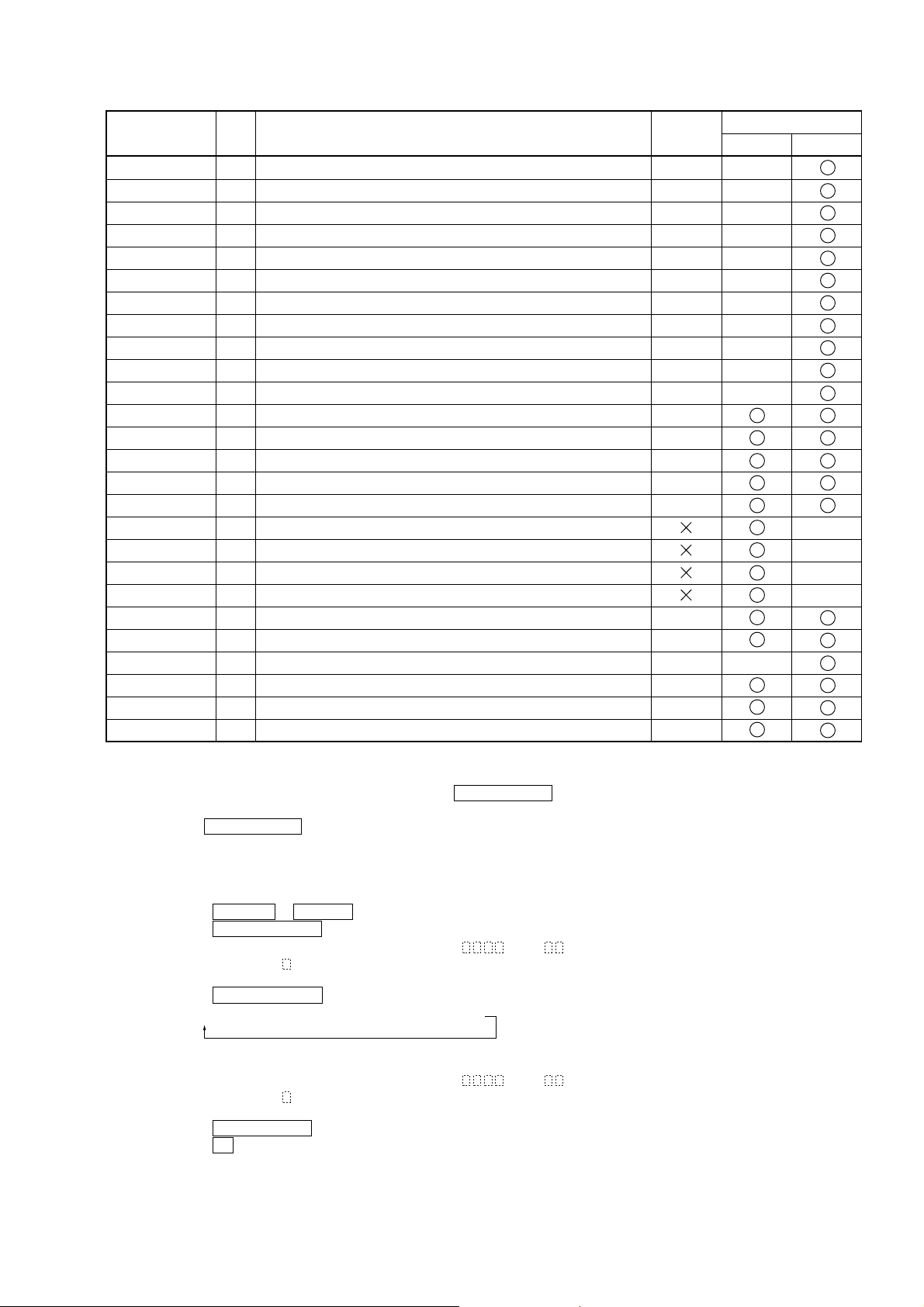
5. Selecting the Test Mode
There are 26 types of test modes as shown below. The groups can be switched by pressing the . “R” or > “R” button. After selecting
the group to be used, press the ENTER/YES “R” button. After setting a certain group, pressing the . “R” or > “R” button
switches modes shown below.
Refer to “Group” in the table for details can be selected.
All items used for servicing can be treated using group [Service]. So be carefully not to enter other groups by mistake.
Note: Do not use the test mode in the [Develop] group.
If used, the unit may not operate normally.
If the [Develop] group is set accidentally, press the MENU/NO “R” button immediately to exit the [Develop] group.
28
HCD-CP505
Display
AUTO CHECK
Err Display
TEMP ADJUST
LDPWR ADJUST
Iop Write
Iop NV Save
EF MO ADJUST
EF CD ADJUST
FBIAS ADJUST
AG Set (MO)
AG Set (CD)
TEMP CHECK
LDPWR CHECK
EF MO CHECK
EF CD CHECK
FBIAS CHECK
ScurveCHECK
VERIFYMODE
DETRK CHECK
0920 CHECK
Iop Read
Iop Compare
ADJ CLEAR
INFORMATION
CPLAY 2MODE
CREC 2MODE
No.
Automatic self-diagnosis
C01
Error history display, clear
C02
Temperature compensation offset adjustment
C03
Laser power adjustment
C04
Iop data writing
C05
Writes current Iop value in read nonvolatile memory using microprocessor
C06
Traverse (MO) adjustment
C07
Traverse (CD) adjustment
C08
Focus bias adjustment
C09
Auto gain output level adjustment (MO)
C10
Auto gain output level adjustment (CD)
C11
Temperature compensation offset check
C12
Laser power check
C13
Traverse (MO) check
C14
Traverse (CD) check
C15
Focus bias check
C16
S-curve check
C17
Nonvolatile memory check
C18
Detrack check
C19
Most circumference check
C25
Iop data display
C26
Comparison with initial Iop value written in nonvolatile memory
C27
Initialization of nonvolatile memory for adjustment values
C28
Display of microprocessor version, etc.
C31
Continuous playback mode
C36
Continuous recording mode
C37
Details
Mark
Group
Check Service
•For details of each adjustment mode, refer to “Section 5 Electrical Adjustments”.
About “Err Display” (C02), please refer to a page 7 self-diagnostic function.
• If a different mode has been selected by mistake, press the MENU/NO “R” button to release that mode.
• Modes with (×) in the Mark column are not used for servicing and therefore are not described in detail. If these modes are set accidentally, press the MENU/NO “R” button to release the mode immediately.
5-1. Operating the Continuous Playback Mode
1. Entering the continuous playback mode
(1) Set the disc in the unit. (Whichever recordable discs or discs for playback only are available)
(2) Press the . “R” or > “R” button to display “CPL
AY 2MODE” (C36).
(3)Press the ENTER/YES “R” button to change the display to “CPLAY2MID”.
(4) When access completes, the display changes to “C = AD = )”.
Note: The numbers “ ” display d show you error rates and ADER.
2. Changing the parts to be played back
(1)Press the ENTER/YES “R” button during continuous playback to change the display as below.
“CPLAY 2MID” t “CPLAY 2OUT” t “CPLAY 2IN”
When pressed another time, the parts to be played back can be moved.
(2) When access completes, the display changes to “C =
AD = )”.
Note: The numbers “ ” display d show you error rates and ADER.
3. Ending the continuous playback mode
(1) Press the MENU/NO “R” button. The display will change to “CPLAY 2MODE” (C36).
(2) Press the Z (MD) button and take out the disc.
Note : The playback start addresses for IN, MID, and OUT are as follows.
IN : 40h cluster
MID : 300h cluster
OUT : 700h cluster
29
HCD-CP505
5-2. Operating the Continuous Recording Mode (Use only when performing self-recording/playback check)
1. Entering the continuous recording mode
(1) Set a recordable disc in the unit.
(2)Press the . “R” or > “R” button to display “CREC 2MODE” (C37).
(3) Press the ENTER/YES “R” button to change the display to “CREC 2MID”.
(4) When access completes, the display changes to “CREC 1(
Note: The numbe s “ ” displayed shows you the recording position addresses.
2. Changing the parts to be recorded
(1) When the ENTER/YES “R” button is pressed during continuous recording, the display changes as below.
“CREC 2MID” t “CREC 2OUT” t “CREC 2IN”
)” and “ MD ” lights up.
MD
When pressed another time, the parts to be recorded can be changed. “ MD ” goes off.
(2) When access completes,
Note: The numbe s “
3. Ending the continuous recording mode
(1)Press the MENU/NO “R” button. The display changes to “CREC 2MODE” (C37) and “ MD ” goes off.
the display changes to “CREC 2( )” and “ MD ” lights up.
” displayed shows you the recording positi n addresses.
MD
MD
MD
(2) Press the Z (MD) button and take out the disc.
Note 1: The recording start addresses for IN, MID, and OUT are as follows.
IN : 40h cluster
MID : 300h cluster
OUT : 700h cluster
Note 2 : The MENU/NO “R” button can be used to stop recording anytime.
Note 3: Do not perform continuous recording for long periods of time above 5 minutes.
Note 4: During continuous recording, be careful not to apply vibration.
6. Functions of Other Buttons
Function
MD N X
x (MD)
M “R”
m “R”
PLAY MODE/DIRECTION
REC MODE
Z (MD)
REPEAT
CLEAR“R”
z REC (MD)
Sets continuous playback when this is pressed in the STOP state. When this is pressed during continuous playback, tracking power servo turns ON/OFF.
Stops continuous playback and continuous recording
The sled moves to the outer circumference only when this is pressed
The sled moves to the inner circumference only when this is pressed
Switches the spindle servo mode (CLV S y CLV A)
Switches the pits or grooves each time the button is pressed
Ejects the disc
Releases the test mode
Clears the setting of pits and groove, and judges pits and groove again.
When it is pressed while servo is turning on, the recording starts from present position.
Contents
7. Automatic Self-diagnosis Function
This test mode performs CREC and CPLAY automatically for mainly checking the characteristics of the optical pick-up.
To perform this test mode, the laser power must first be checked.
Perform AUTO CHECK after the laser power check and Iop Compare.
Procedure:
1. Display “AUTO CHECK” and press the ENTER/YES “R” button. If “LDPWR
check has not been performed. In this case, perform the laser power check and Iop Compare (C27), and then repeat from step1.
2. If a disc is in the mechanical deck, it will be ejected forcibly.
“DISC IN” will be displayed in this case. Load a test disc (MDW-74/GA-1) which can be recorded.
3. If a disc is loaded at step 2, the check will start automatically.
4. When “XX CHECK” is displayed, the item corresponding to XX will be performed.
When “06 CHECK” completes, the disc loaded at step 2 will be ejected. “DISC IN” will be displayed. Load the check disc (TDYS-1).
5. When the disc is loaded in step 4, the check will automatically be resumed from “07 CHECK”.
6. After completing to “0C CHECK”, check OK or NG will be displayed. If all items are OK, “CHK ALL OK” will be displayed. If any
item is NG, it will be displayed as “NG:xxxx”.
When “CHK ALL OK” is displayed, it means that the optical pick-up is normal. Check the operations of other parts (spindle motor, sled
motor, etc.).
When displayed as “NG:xxxx”, it means that the optical pick-up is faulty. In this case, replace the optical pick-up.
” is displayed, it means that the laser power
30
 Loading...