

Sony HCDCP-500-MD Service manual
HCD-CP500K/CP500MD
SERVICE MANUAL
Ver. 1.2 2005. 02
HCD-CP500K/CP500MD is the Amplifier,
MD deck, CD player , Tape pla yer and Tuner
section in CMT-CP500K/CP500MD.
CD
Section
MD
Section
Tape deck
Section
US Model
Canadian Model
AEP Model
UK Model
E Model
Australian Model
Chinese Model
HCD-CP500MD
Korea Model
HCD-CP500K
Model Name Using Similar Mechanism New
CD Mechanism Type CDM55F-K4BD43
Base Unit Type BU-K4BD43
Optical Pick-up Type KSM-213DHAP
Model Name Using Similar Mechanism New
MD Mechanism Type MDM-7B
Optical Pick-up Type KMS-260B
Model Name Using Similar Mechanism New
Tape Transport Mechanism T ype Mech deck
SPECIFICATIONS
Amplifier section
For the U.S. model
AUDIO POWER SPECIFICATIONS
POWER OUTPUT AND TOTAL
HARMONIC DISTORTION:
With 6-ohm loads, both channels driven, from
70 - 20,000 Hz; rated 18 watts per channel
minimum RMS power, with no more than 0.9%
total harmonic distortion from 250 milliwatts to
rated output.
US, Canadian model:
Continuous RMS power output (reference):
Total harmonic distortion: less than 0.07% (6 ohms at
1 kHz, 18 W)
35 + 35 W
(6 ohms at 1 kHz, 10%
THD)
AEP, UK model:
DIN power output (rated): 30 + 30 W
Continuous RMS power output (reference):
Music power output (reference):
Other models:
The following measured at 230 V AC, 60 Hz
DIN power output (rated): 30 + 30 W
Continuous RMS power output (reference):
The following measured at 220 V AC, 60 Hz
DIN power output (rated): 24 + 24 W
Continuous RMS power output (reference):
(6 ohms at 1 kHz, DIN)
35 + 35 W
(6 ohms at 1 kHz, 10%
THD)
85 + 85 W
(6 ohms at 1 kHz, DIN)
35 + 35 W
(6 ohms at 1 kHz, 10%
THD)
(6 ohms at 1 kHz, DIN)
27 + 27 W
(6 ohms at 1 kHz, 10%
THD)
— Continued on next page —
MICRO HI-FI COMPONENT SYSTEM
9-873-216-03
2005B16-1
© 2005.02
Sony Corporation
Personal Audio Group
Published by Sony Engineering Corporation

HCD-CP500K/CP500MD
Specifications (continued)
Inputs
ANALOG IN (phono jacks):
DIGITAL OPTICAL IN (Supported sampling
frequencies: 32 kHz, 44.1 kHz and 48 kHz)
Outputs
PHONES (stereo minijack):
SPEAKER: Accepts impedance of 6 to
CD player section
System Compact disc and digital
Laser Semiconductor laser
Wavelength 780 – 790 nm
Frequency response 2 Hz – 20 kHz (±0.5 dB)
Tape player section
Recording system 4-track 2-channel stereo
Frequency response 50 – 13,000 Hz (±3 dB),
Wow and flutter ±0.15% W. Peak (IEC)
Sensitivity 250 mV,
impedance 47 kilohms
Accepts headphones with
an impedance of 8 ohms
or more
16 ohms
audio system
(λ = 780 nm)
Emission
duration: continuous
using a Sony TYPE I
cassette
0.1% W. RMS (NAB)
±0.2% W. Peak (DIN)
General
Power requirements
US and Canadian model: 120 V AC, 60 Hz
Thai and Chinese model: 220 V AC, 50/60 Hz
AEP and UK model: 230 V AC, 50/60 Hz
Australian and Hong Kong model:
Other models: 110 – 120 V or 220 –
Power consumption
AEP and UK model: See the nameplate
Other models: See the nameplate
Dimensions (w/h/d) Approx. 190 × 252 ×
Mass Approx. 7.0 kg
Supplied accessories Remote commander (1)
Design and specifications are subject to change
without notice.
220 – 240 V AC,
50/60 Hz
240 V AC , 50/60 Hz
Adjustable with voltage
selector
0.5 W (in the standby
mode)
335 mm incl. projecting
parts and controls
AM loop antenna (1)
FM wire antenna (1)
Batteries (2)
MD deck section
System MiniDisc digital audio
Laser Semiconductor laser
Sampling frequency 44.1 kHz
Frequency response 5 Hz – 20 kHz
system
(λ =780 nm)
Emission duration:
continuous
Tuner section
FM stereo, FM/AM superheterodyne tuner
FM tuner section
Tuning range
US and Canadian model: 87.5 – 108.0 MHz
Other models: 87.5 – 108.0 MHz
Antenna FM wire antenna
Antenna terminals 75 ohm unbalanced
Intermediate frequency 10.7 MHz
AM tuner section
Tuning range
US and Canadian model: 530 – 1,710 kHz
AEP and UK model: 531 – 1,602 kHz
Other models: 530 – 1,710 kHz
Antenna AM loop antenna, external
Intermediate frequency 450 kHz
(100-kHz step)
(50-kHz step)
(with the tuning interval
set at 10 kHz)
531 – 1,710 kHz
(with the tuning interval
set at 9 kHz)
(with the tuning interval
set at 9 kHz)
(with the tuning interval
set at 10 kHz)
531 – 1,602 kHz
(with the tuning interval
set at 9 kHz)
antenna terminal
2
HCD-CP500K/CP500MD
TABLE OF CONTENTS
Self-diagnosis display
This system has a Self-diagnosis display
function to let you know if there is a system
malfunction. The display shows a code made
up of three letters and a message alternately to
show you the problem. To solve the problem
refer to the following list. If any problem
persists, consult your nearest Sony dealer.
C11/Protected
The MD is protected against erasure.
Remove the MD and slide the tab to close the
slot (see page 16).
C12/Cannot Copy
You tried to record a CD or MD with a format that
the system does not support, such as a CD-ROM.
p Remove the disc and turn off the system once,
then turn it on again.
C13/REC Error
Recording could not be performed properly.
p Move the system to a stable place, and start
recording over from the beginning.
The MD is dirty or scratched, or the MD does not
meet the standards.
p Replace the MD and start recording over from
the beginning.
1. SERVICING NOTES ······················································ 4
2. GENERAL ·········································································· 9
3. DISASSEMBLY ······························································ 11
4. TEST MODE··································································· 20
5. MECHANICAL ADJUSTMENTS ···························· 26
6. ELECTRICAL ADJUSTMENTS······························26
7. DIAGRAMS
7-1. CIRCUIT BOARDS LOCATIONS ··································· 41
7-2. BLOCK DIAGRAM – CD SECTION – ··························· 42
BLOCK DIAGRAM – MAIN SECTION – ······················ 43
BLOCK DIAGRAM – MD SECTION – ·························· 44
BLOCK DIAGRAM – PANEL SECTION – ···················· 45
7-3. PRINTED WIRING BOARD – CD BOARD – ················ 46
7-4. SCHEMATIC DIAGRAM – CD BOARD – ····················· 47
7-5. PRINTED WIRING BOARD – BD BOARD – ················ 48
7-6. SCHEMATIC DIAGRAM – BD BOARD (1/2) – ············ 49
7-7. SCHEMATIC DIAGRAM – BD BOARD (2/2) – ············ 50
7-8. PRINTED WIRING BOARDS – AUDIO SECTION – ···· 51
7-9. SCHEMATIC DIAGRAM – AUDIO SECTION (1/2) –··· 52
7-10.SCHEMATIC DIAGRAM – AUDIO SECTION (2/2) –··· 53
7-11.PRINTED WIRING BOARD – TC BOARD – ················· 54
7-12.SCHEMATIC DIAGRAM – TC BOARD –······················ 55
7-13.PRINTED WIRING BOARD – DIGITAL BOARD – ······ 56
7-14 SCHEMATIC DIAGRAM – DIGITAL BOARD –··········· 57
7-15.
PRINTED WIRING BOARDS – CONTROL SECTION –
7-16 SCHEMATIC DIAGRAM – CONTROL BOARD – ········ 59
7-17.PRINTED WIRING BOARD – POWER BOARD –········ 60
7-18.SCHEMATIC DIAGRAM – POWER BOARD – ············· 60
7-19.IC BLOCK DIAGRAMS ·················································· 61
7-20.IC Pin Function Description ·············································· 63
··· 58
8. EXPLODED VIEWS ····················································· 71
9. ELECTRICAL PARTS LIST····································· 78
C13/Read Error
The MD deck cannot read the disc information
properly.
p Remove the MD once, then load it again.
C14/Toc Error
The MD deck cannot read the disc information
properly.
p Replace the MD.
p Erase all the recorded contents of the MD using
All Erase Function (see page 27).
C41/Cannot Copy
The sound source is a copy of commercially
available music software.
p The Serial Copy Management System prevents
making a digital copy (see page 47).
3
HCD-CP500K/CP500MD
SECTION 1
SERVICING NOTE
NOTES ON HANDLING THE OPTICAL PICK-UP
BLOCK OR BASE UNIT
The laser diode in the optical pick-up block may suffer electrostatic
break-down because of the potential difference generated by the
charged electrostatic load, etc. on clothing and the human body.
During repair, pay attention to electrostatic break-down and also
use the procedure in the printed matter which is included in the
repair parts.
The flexible board is easily damaged and should be handled with
care.
FOR CD
NOTES ON LASER DIODE EMISSION CHECK
The laser beam on this model is concentrated so as to be focused on
the disc reflective surface by the objective lens in the optical pickup block. Therefore, when checking the laser diode emission,
observe from more than 30 cm away from the objective lens.
FOR MD
NOTES ON LASER DIODE EMISSION CHECK
Never look into the laser diode emission from right above when
checking it for adjustment. It is feared that you will lose your sight.
Laser component in this product is capable
of emitting radiation exceeding the limit for
Class 1.
SAFETY CHECK-OUT
After correcting the original service problem, perform the following
safety check before releasing the set to the customer:
Check the antenna terminals, metal trim, “metallized” knobs, screws,
and all other exposed metal parts for AC leakage.
Check leakage as described below.
LEAKAGE TEST
The AC leakage from any exposed metal part to earth ground and
from all exposed metal parts to any exposed metal part having a
return to chassis, must not exceed 0.5 mA (500 microamperes.).
Leakage current can be measured by any one of three methods.
1. A commercial leakage tester, such as the Simpson 229 or RCA
WT-540A. Follow the manufacturers’ instructions to use these
instruments.
2. A battery-operated AC milliammeter. The Data Precision 245
digital multimeter is suitable for this job.
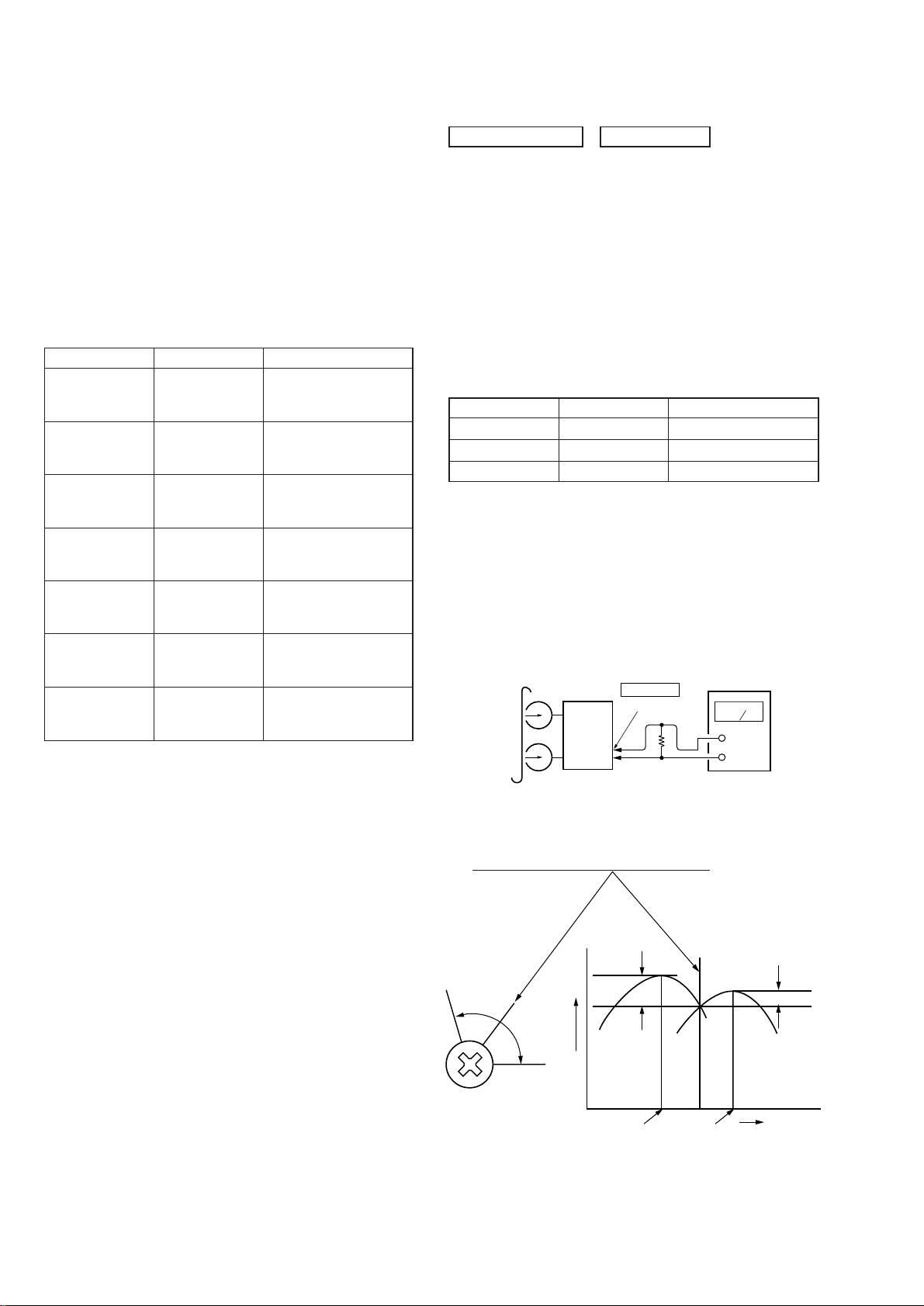
3. Measuring the voltage drop across a resistor by means of a V OM
or battery-operated A C voltmeter . The “limit” indica tion is 0.75
V, so analog meters must have an accurate low-voltage scale.
The Simpson 250 and Sanwa SH-63Trd are examples of a
passive V OM that is suitable. Nearly all battery operated digital
multimeters that have a 2 V A C range are suitable. (See Fig. A)
T o Exposed Metal
Parts on Set
This appliance is classified as a CLASS 1 LASER product. The
CLASS 1 LASER PRODUCT MARKING is located on the rear
exterior.
This caution
label is
located inside
the unit.
CAUTION
Use of controls or adjustments or performance of procedures
other than those specified herein may result in hazardous radiation
exposure.
Notes on chip component replacement
• Never reuse a disconnected chip component.
• Notice that the minus side of a tantalum capacitor may be
damaged by heat.
AC
0.15 µF
Fig. A. Using an A C v oltmeter to check A C leakage.
SAFETY-RELATED COMPONENT WARNING!!
COMPONENTS IDENTIFIED BY MARK 0 OR DOTTED LINE WITH
MARK 0 ON THE SCHEMATIC DIAGRAMS AND IN THE PARTS
LIST ARE CRITICAL TO SAFE OPERATION. REPLACE THESE
COMPONENTS WITH SONY PARTS WHOSE PART NUMBERS
APPEAR AS SHOWN IN THIS MANUAL OR IN SUPPLEMENTS
PUBLISHED BY SONY.
ATTENTION AU COMPOSANT AYANT RAPPORT
LES COMPOSANTS IDENTIFÉS P AR UNE MARQUE 0 SUR LES
DIAGRAMMES SCHÉMA TIQUES ET LA LISTE DES PIÈCES SONT
CRITIQUES POUR LA SÉCURITÉ DE FONCTIONNEMENT. NE
REMPLACER CES COMPOSANTS QUE PAR DES PIÈSES SONY
DONT LES NUMÉROS SONT DONNÉS DANS CE MANUEL OU
DANS LES SUPPÉMENTS PUBLIÉS PAR SONY.
1.5 kΩ
Earth Ground
À LA SÉCURITÉ!
Voltmeter
(0.75 V)
Flexible Circuit Board Repairing
• Keep the temperature of soldering iron around 270˚C
during repairing.
• Do not touch the soldering iron on the same conductor of the
circuit board (within 3 times).
• Be careful not to apply force on the conductor when soldering
or unsoldering.
4
DRAWING OUT THE TRAY DURING POWER OUT
w
Tray
HCD-CP500K/CP500MD
Move the cam block in the direction
of the arrow with a finger.
CLEANING THE OPTICAL PICK-UP (CD PLAYER)
CD mechanism deck
Floating scre
Clean the lens block
with applicator.
Optical pick-up block
5
HCD-CP500K/CP500MD
SERVICE POSITION OF THE MD MECHANISM DECK
MD mechanism deck
(MDM-7B)
BD board
MD DIGITAL board
CN1001
CN304
MAIN board
CN301
CN801
SERVICE POSITION OF THE CD MECHANISM DECK
LOADING board
CD mechanism deck
(CDM55F-K4BD43)
CD board
CN101
MAIN board
CN308
CN1
CN302
6
SERVICE POSITION OF THE TAPE MECHANISM DECK
k
HCD-CP500K/CP500MD
Tape mechanism dec
CN303
CN301
7
HCD-CP500K/CP500MD
B
JIG FOR CHECKING BD (MD) BOARD WAVEFORM
The special jig (J-2501-196-A) is useful for checking the waveform of the BD (MD) board. The names of ter minals and the checking items
to be performed are shown as follows.
GND : Ground
I+3V : For measuring IOP (Check the deterioration of the optical pick-up laser)
IOP : For measuring IOP (Check the deterioration of the optical pick-up laser)
TE : TRK error signal (Traverse adjustment)
VC : Reference level for checking the signal
RF : RF signal (Check jitter)
FE : Focus error signal
I+3V
GND
FE
RF
IOP
TE
VC
I+3V
IOP
GND
TE
FE
VC
RF
CN105
1
I+3V
Iop
GND
TE
FE
VC
RF
7
for
MDM-7
8
SECTION 2
GENERAL
1 2 5 863 47
HCD-CP500K/CP500MD
wj
wh
wg
wf
wd
ws
wa
w;
9
q;
qa
qs
qd
qf
qg
qh
qjqkql
BASS wd (40)
CD EJECT Z qh (8, 9, 16, 50)
CD x qj (9, 10, 17, 38)
CD u qk (9, 10)
DSG wh (40)
ENTER/START 5 (17, 18, 38,
39)
FUNCTION wf (9, 10, 13, 14, 19,
22, 23, 37, 39, 43)
MD EJECT Z ql (13, 24)
MD REC z qg (19, 22, 23)
MD u qd (13 – 15, 19)
MD x qf (13, 15, 17 – 20, 38,
39)
PHONES jack wa
PLAY MODE DIRECTION wj
(9, 10, 13 – 15, 24, 37 – 39)
PUSH OPEN/CLOSE Z 6 (37)
REC MODE 3 (20, 50)
Remote sensor 1
REPEAT 2 (9, 13, 34)
STEREO/MONO 2 (35)
SYNCHRO 4 (17, 18, 38)
TAPE REC z 0 (39)
TAPE Y 7 (37 –39)
TAPE x 8 (18, 37 – 39)
TAPE X 9 (37, 39)
TREBLE ws (40)
TUNER BAND qs (34, 35, 50)
TUNING MODE wj (34, 35)
TUNING –/+ qa (34, 35)
VOLUME w; (41)
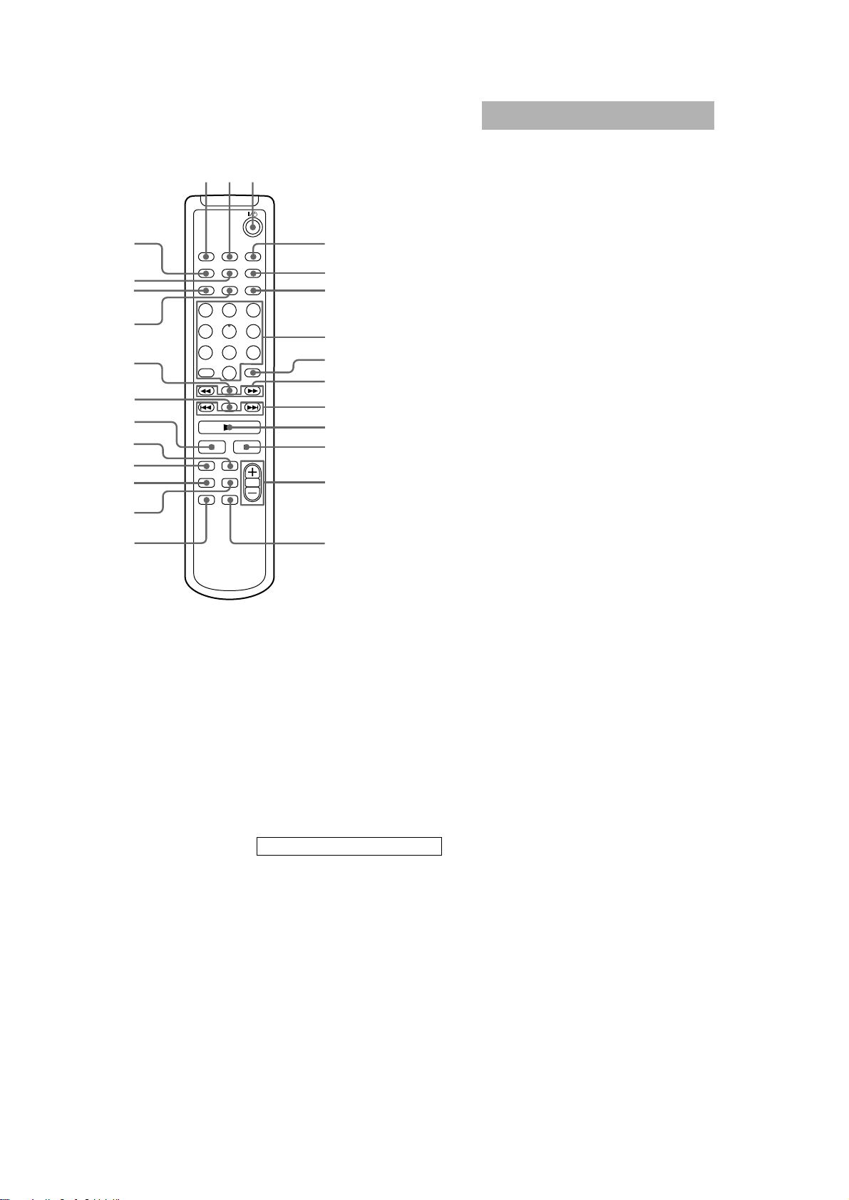
BUTTON DESCRIPTIONS
. > qa (9, 10, 13 – 15)
m M qa (9, 13, 37)
@/1 (power) wg (7, 16, 24, 35, 41,
43, 50)
9
HCD-CP500K/CP500MD
123
wh
wg
wf
wd
ws
wa
w;
ql
qk
qj
qh
4
5
6
7
8
9
0
qa
qs
qd
Setting the time
1
Turn on the system.
2
Press CLOCK/TIMER SET on the
remote.
If you are setting the clock for the first time,
go to step 5.
3
Press . or > on the remote
repeatedly until “CLOCK SET?”
appears in the display.
4
Press ENTER/YES on the remote.
The hour indication flashes.
5
Press . or > on the remote
repeatedly to set the hour.
6
Press ENTER/YES or CURSORt on
the remote.
The minute indication flashes.
7
Press . or > on the remote
repeatedly to set the minute.
8
Press ENTER/YES on the remote.
The clock will begin operating.
To reset the system clock
Start over from step 1.
qg
BASS/TRE 5 (40)
CD qj (9 – 11)
CLEAR 8 (10, 14, 15, 25, 36)
CLOCK/TIMER SELECT 2
(42, 43)
CLOCK/TIMER SET 4 (7, 41,
42)
CURSOR T/t 9 (7, 12, 25)
DISPLAY wa (8, 10, 11, 15, 19,
36)
DSG qf (40)
ENTER/YES 6 (7, 10, 12, 14,
20 – 23, 25 – 34, 36, 41 – 43)
FUNCTION qg (9, 10, 13, 14, 19,
22, 23, 37, 39, 43)
MD qk (13, 14, 25, 27 – 30, 32)
MENU/NO wf (12, 21 – 24, 26 –
34)
NAME EDIT/SELECT wd (11,
12, 24, 25, 36)
qf
Number buttons 7 (9, 10, 12, 14,
15, 25, 35)
PLAY MODE wh (9, 10, 13 – 15,
24, 32)
REPEAT wg (9, 13)
SCROLL ws (12, 15, 26)
SLEEP 1 (40)
TAPE qh
TUNER BAND ql (34, 35)
VOLUME +/– qd (41)
BUTTON DESCRIPTIONS
@/1 (power) 3 (7, 16, 24, 35, 41,
43)
m M 9 (28, 30)
. > 0 (7, 11, 12, 21 – 23,
25 – 34, 40 – 42)
N qa (9, 10, 13, 15, 23)
x qs (23)
X w; (9, 13, 28)
10
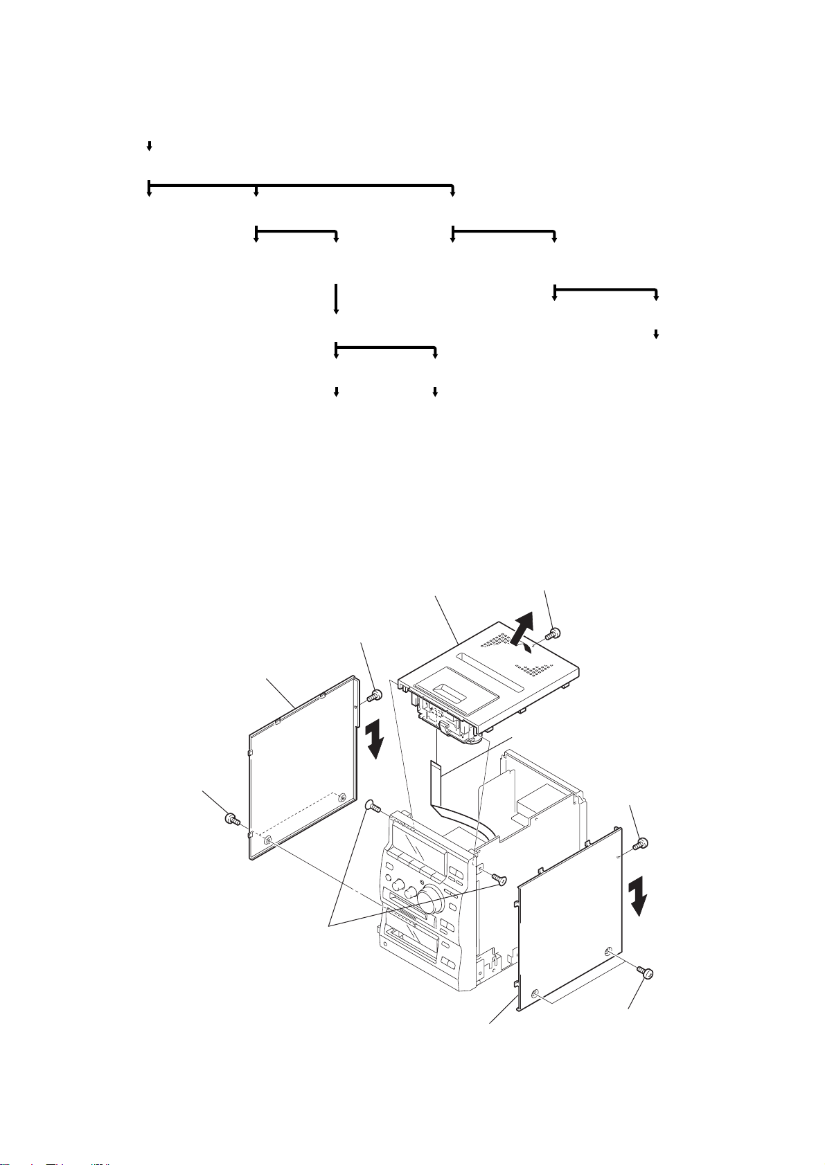
• The equipment canbe removed using the following procedure.
)
Set
Upper cover and case (L), (R)
(Page 11)
HCD-CP500K/CP500MD
SECTION 3
DISASSEMBLY
Tape mechanism deck
(Page 12)
Note: Follow the disassembly procedure in the numerical order given.
Front panel section
(Page 12)
Panel section
(Page 13)
MD mechanism
deck section
(Page 15)
MD base unit
(Page 15)
BD board
(Page 16)
Motor section
(Page 16)
Over write head (HR901)
(Page 17)
Optical pick-up (MD)
(Page 17)
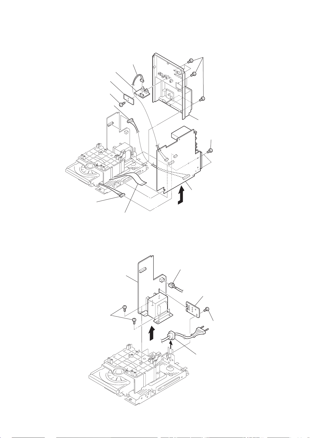
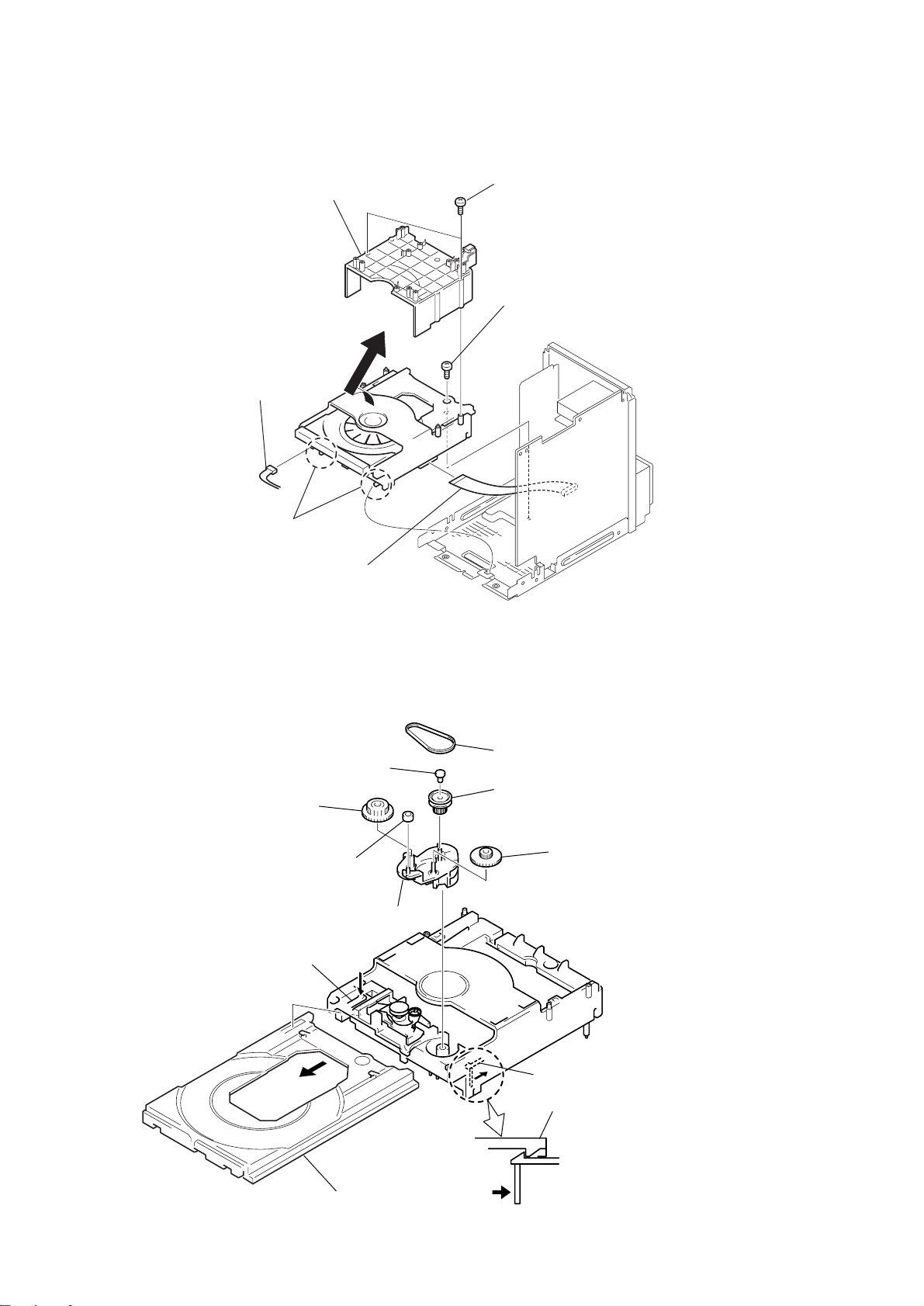
3-1. UPPER COVER AND CASE (L), (R)
9
Upper cover
(Remove in the direction
of the arrow.)
2
screw
(+ BTP 3 x 8)
3
Case (L)
(Remove in the direction
of the arrow.)
Back panel and MAIN board
(Page 14)
POWER board
(Page 14)
CD mechanism deck
section
(Page 18)
Tray, gear and D cam
section (CDM55)
(Page 18)
7
(+ BTP 3 x 8)
CD base unit (CDM55)
(Page 19)
Optical pick-up (CD)
block section (KSM-213 DHAP)
(Page 19)
screw
1
T wo screws
(Case 3 TP 2)
8
Two screws
(+ KTP 3 x 8)
q;
Flat cable (18 core)
(CN301)
6
Case (R)
(Remove in the direction
of the arrow.)
5
screw
(+ BTP 3 x 8)
4
T wo screws
(Case 3 TP 2
11
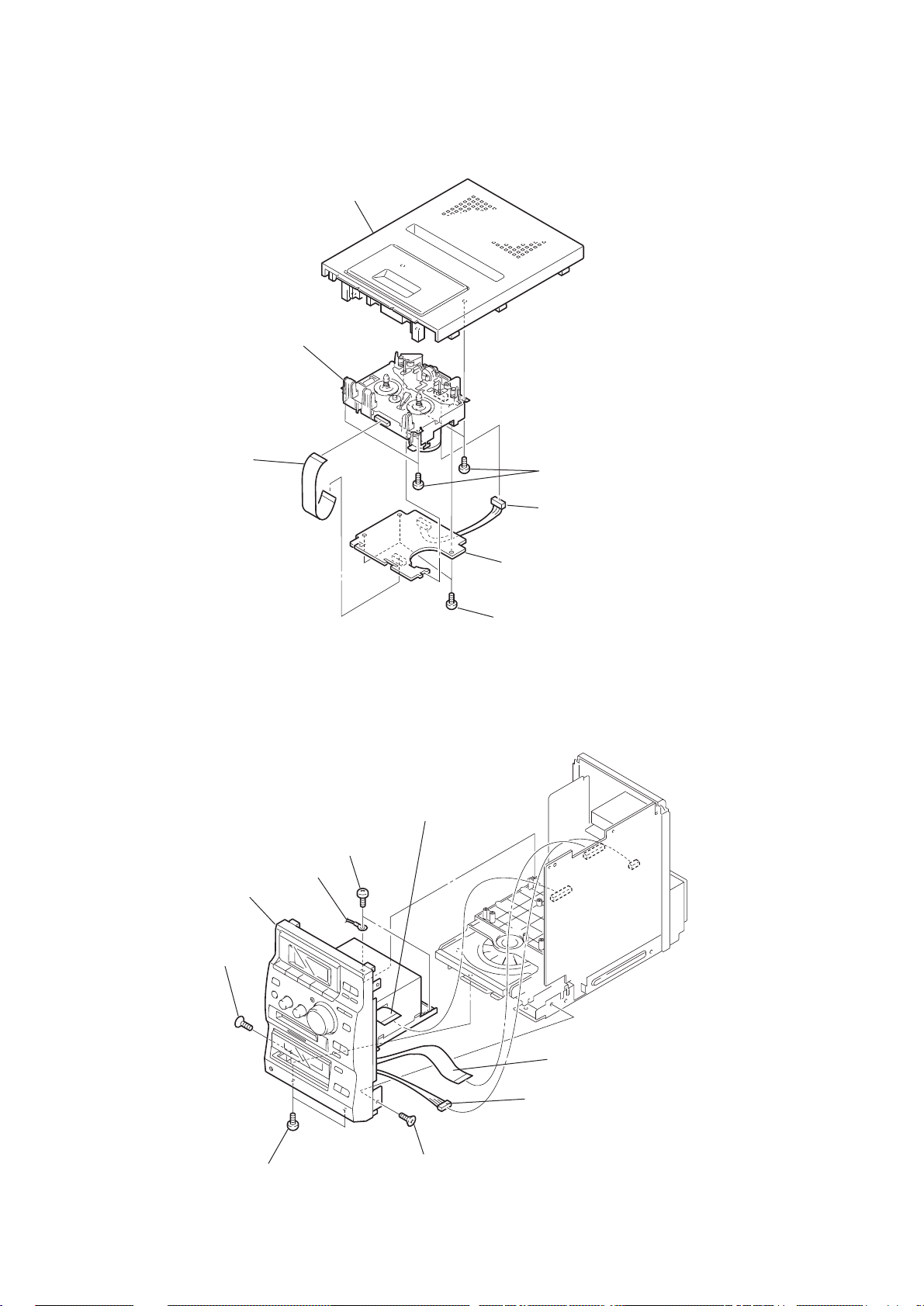
HCD-CP500K/CP500MD
)
3-2. TAPE MECHANISM DECK
6
Tape
1
Flat cable
(12 core) (CN302)
Top panel
mechanism deck
5
Four screws
(+BTP 3 x 8)
3
Connector (CN301
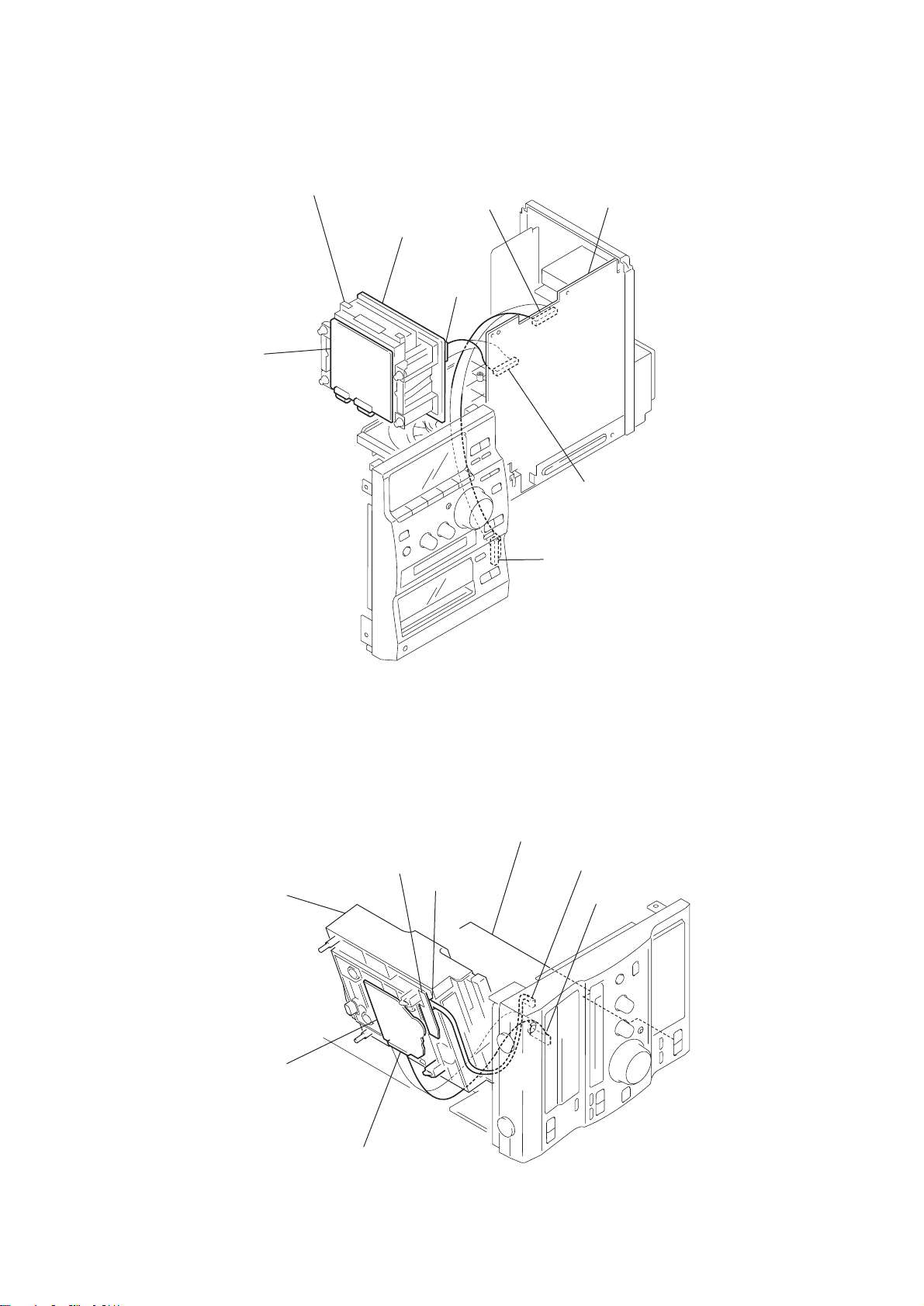
3-3. FRONT PANEL SECTION
9
Front panel section
7
Screw
(+KTP 3 x 8)
1
(+BTP 3 x 8)
2
Earth wire
Two screws
3
Flat cable (25 core)
(CN301)
4
TC board
2
Three screws
(+BVTT 2.6 x 5)
12
8
Two screws
(+BTP 3 x 8)
6
Screw
(+KTP 3 x 8)
4
Flat cable (25 core)
(CN304)
5
Connector (C306)
s
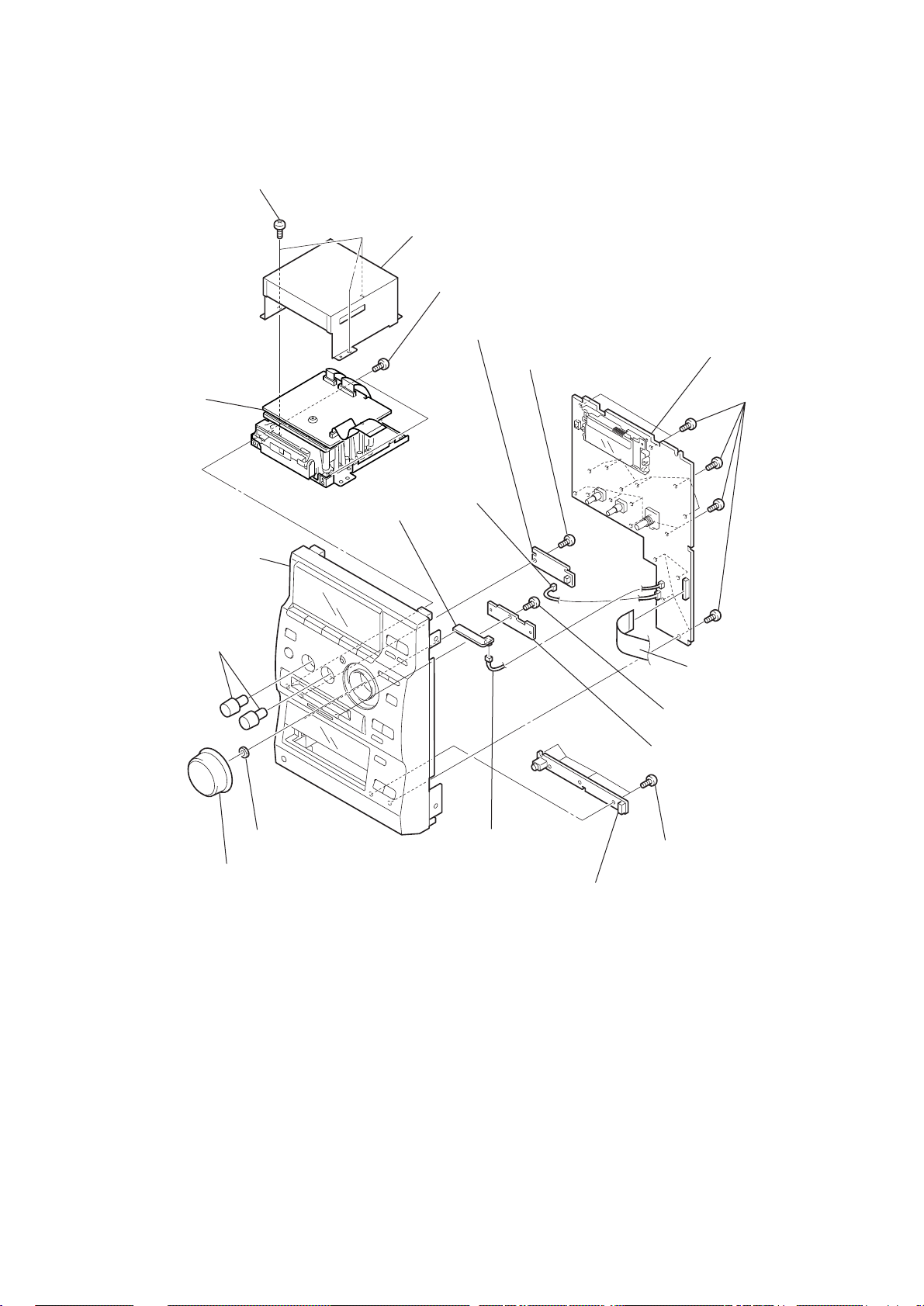
3-4. PANEL SECTION
4
Three screws (+BTP 3 x 8)
7
MD block
qf
CD-PRISM
board
5
MD cover
6
Two screws (+BTP 3 x 8)
qa
MD-INDICATE board
8
Connector
(CN806)
q;
Screw
(+BVTP 2.6 x 8)
HCD-CP500K/CP500MD
ql
CONTROL board
qj
Eighteen screw
(+BVTP 2.6 x 8)
Front panel
2
T wo knobs
(BASS/TREBLE)
3
1
Knob(VOL)
Hexagon nut
9
Connector
(CN808)
qs
Screw (+BVTP 2.6 x 8)
qd
Prism retainer board
qg
Four screws
(+BVTP 2.6 x 8)
qh
HEAD PHONE board
qk
Flat cable (25 core)
(CN801)
13
HCD-CP500K/CP500MD
x
3-5. BACK PANEL AND MAIN BOARD
qa
OPTICAL board
0
Optical retainer board
9
Screw
(+BTP 3 x 8)
1
Connector (CN902)
2
Connector (CN551)
5
Eight screws
(+BTP 3 x 8)
6
Back panel
7
Two screws
(+BTP 3 x 12)
3-6. POWER BOARD
3
Connector
(CN308)
5
Four screws
4
Flat cable (22 core)
(CN302)
6
POWER board
(+BVTP 4 x 8)
8
MAIN board
2
Connector (CN901)
4
Power retainer board
3
Screw
(+BTP 3
14
1
Cord stopper
k
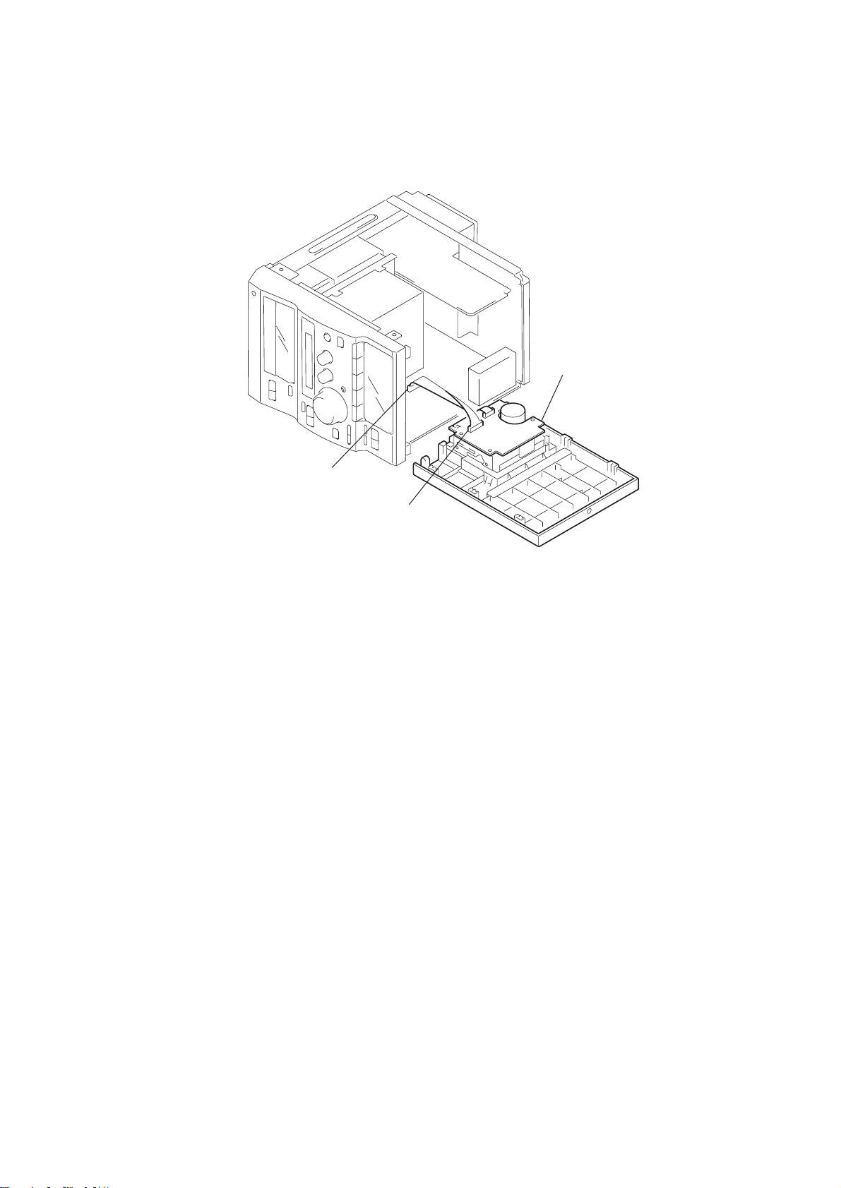
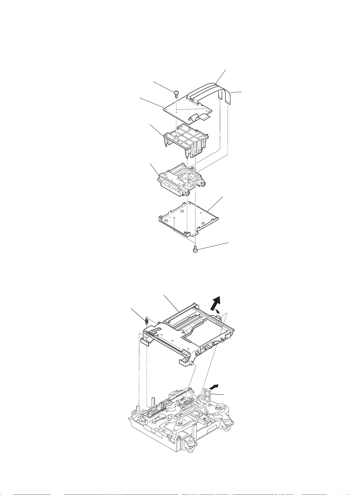
3-7. MD MECHANISM DECK SECTION
3
T wo screws
(+BTP 3 x 8)
4
DIGITAL board
6
MD cover
8
MD mechanism deck
HCD-CP500K/CP500MD
1
Flat cable (17 core)
(CN103)
2
Flat cable (27 core)
(CN102)
3-8. MD BASE UNIT
1
Spring
3
Holder assy
7
MD cover
5
T wo screws
(+BTP 3 x 8)
2
Hoo
15
HCD-CP500K/CP500MD
)
s
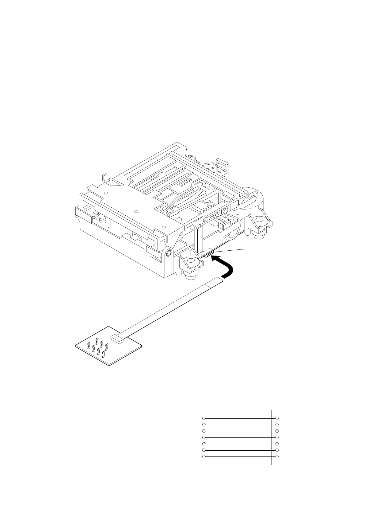
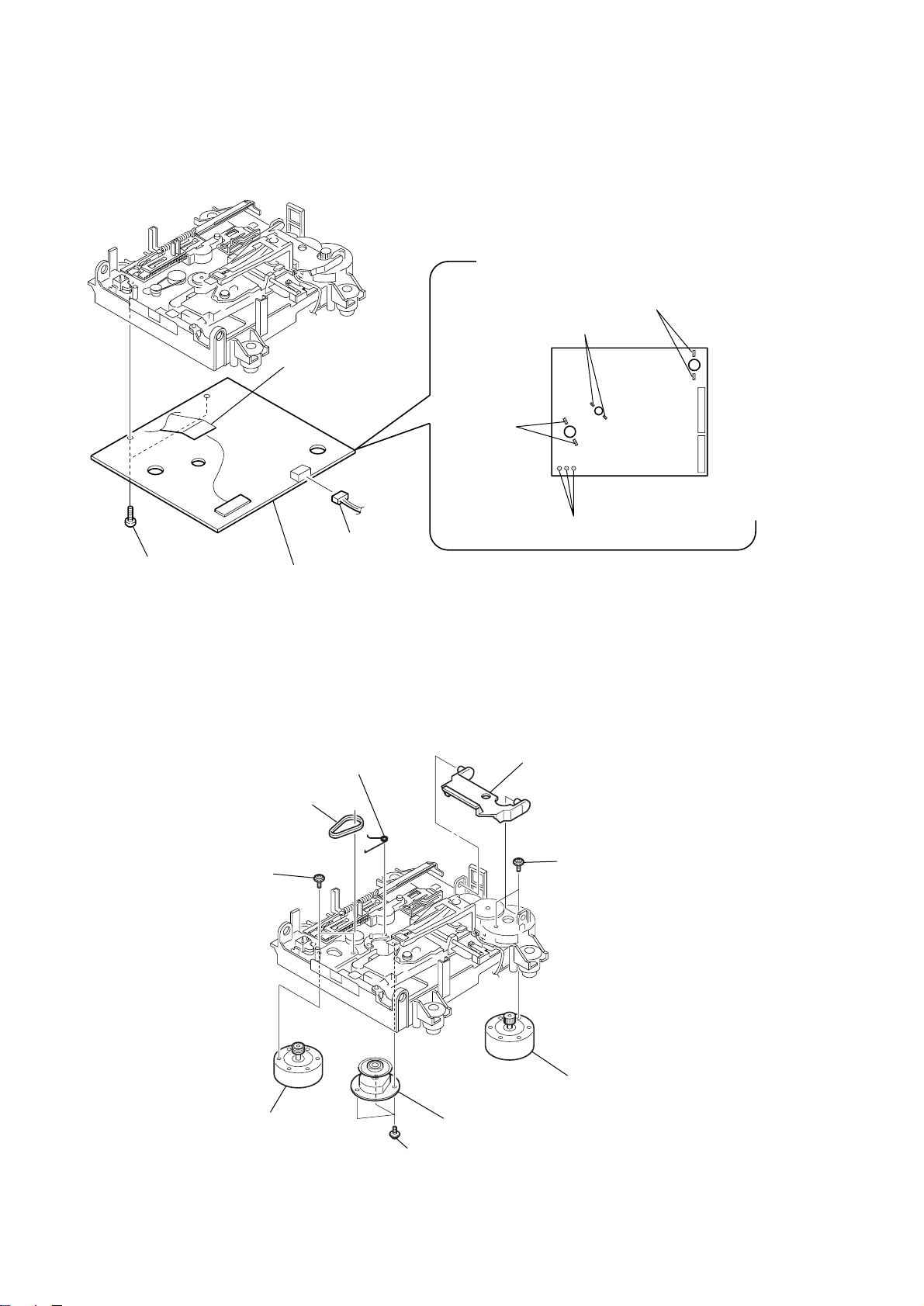
3-9. BD BOARD
6
Flexible board
(CN101)
2
Remove the solders
(Two portion)
(SPINDLE motor)
1
Remove the solder
(Two portion)
(SLED motor)
M102
5
Two screws
(+BTP2 x 6)
3-10. MOTOR SECTION
7
8
BD board
3
Spring (spindle), tortion
2
Belt (CDM55)
Connector (CN104)
3
Remove the solders
(Two portion)
(LOADING motor)
1
Lever (head)
M101
M103
S102
4
Remove the solders
(Three portion)
16
4
T wo screws
(+PWH 1.7 x 3.5)
5
Loading motor
(M103)
7
Spindle motor
(M101)
6
Three screws
(TAPPING M1.7)
8
T wo screws
(+PWH 1.7 x 3.5
9
Sled motor
(M102)
)
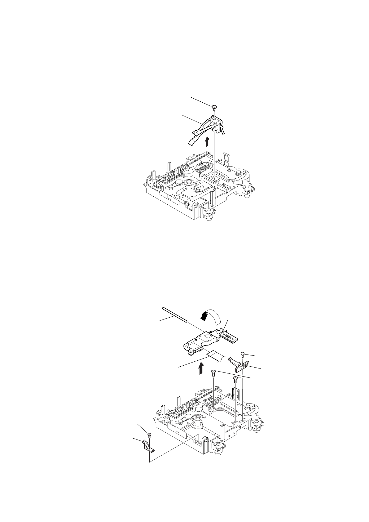
3-11. OVER WRITE HEAD (HR901)
1
Screw (P 1.7 x 6)
2
Over write head
(HR901)
HCD-CP500K/CP500MD
3-12. OPTICAL PICK-UP (MD)
1
Screw (+BTP 2 x 6)
2
Base (BU-D)
6
Main shaft
7
Flexible board
8
Optical pick-up (for MD)
5
3
Screw (+BTP 2 x 6
4
Base (BU-A)
Screw (+KTP2 x 6)
17
HCD-CP500K/CP500MD
3-13. CD MECHANISM DECK SECTION
2
MPEG braket
5
Connector (CN1)
1
Two screws
(+BTP 3 x 8)
3
Screw
(+BTP 3 x 8)
6
CD mechanism deck
(Two claws)
4
Flat cable (22core)
(CN101)
3-14. TRY, GEAR AND D CAM SECTION (CDM55)
5
Spacer (55)
8
Gear (B)
7
Roller
0
Cam (CDM55)
2
Push the claw in tne
direction of the arrow
C
.
C
4
Belt (CDM55)
6
Pulley (LDG)
9
Gear (A)
18
A
3
Pull out the tray.
B
B
1
Pull out the tray in the arrow direction A,
and release the lock while pressing
this claw in the arrow direction
Release
B
.
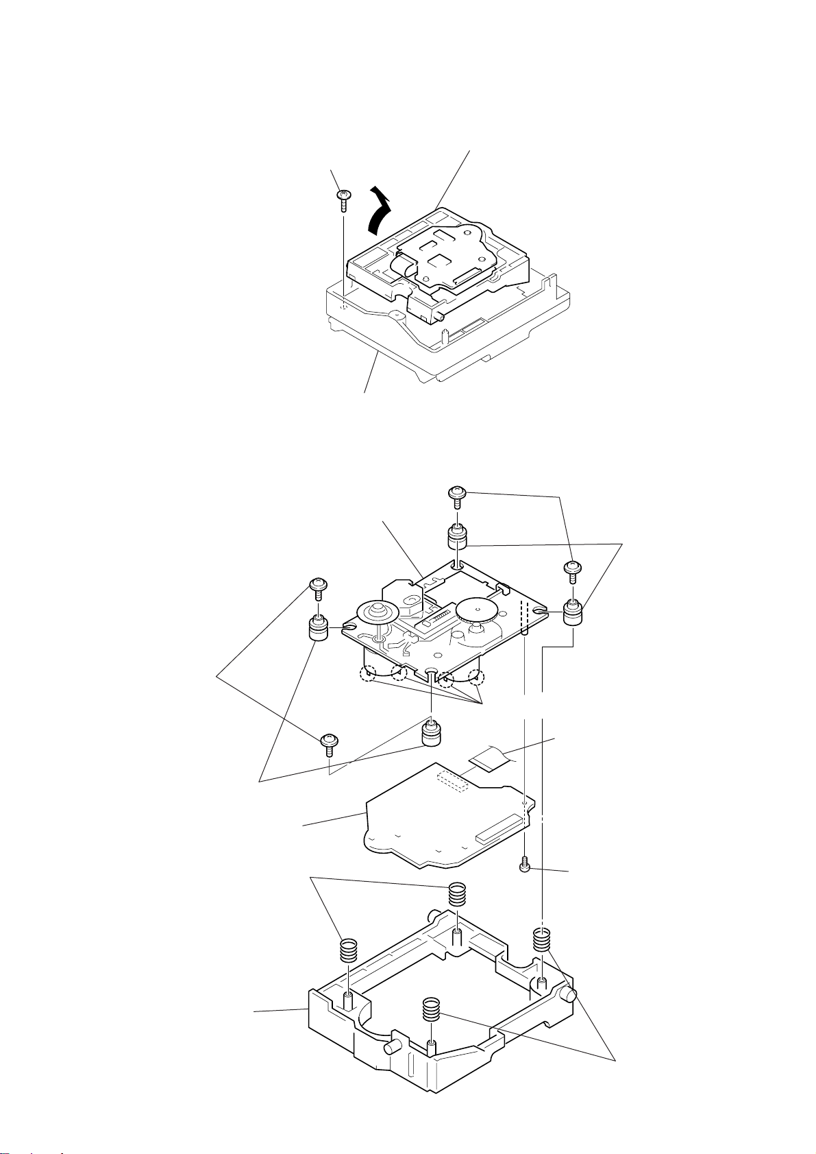
3-15. CD BASE UNIT (CDM55)
)
Floating screw
1
(PTPWH M2.6)
3
Chassis (F)
A
HCD-CP500K/CP500MD
2
Remove the HOLDER (BU
assembly in the direction
of the arrow A.
3-16. OPTICAL PICK-UP (CD) BLOCK SECTION
(KSM-213DHAP)
qs
Optical pick-up (CD) block
@
(KSM-213DHAP)
3
T wo screws
@
(+PTPWH M2.6)
7
Two insulators
qa
CD board
2
T wo screws
@
(+PTPWH M2.6)
q;
Remove the four solders.
1
Flat cable (16 core)
8
T wo insulators
4
Holder (213D)
5
T wo springs
9
screw
(+ BTP 2.6 x 6)
6
T wo springs
19

HCD-CP500K/CP500MD
SECTION 4
TEST MODE
Note 1:About “R”
As this unit has only a few buttons, some operations require the use of remote commander (RM-SCP500/provided with unit: 1-476-754-11)
buttons. These operations are indicated as “R” in this manual.
Example: MENU/NO “R” ...Press the [MENU/NO] button of the remote commander.
Note 2:Incorrect operations may be performed if the MD test mode is not entered properly.
In this case, press the ?/1 button to turn the power off, and retry to enter the MD test mode.
[Cold Reset]
• The cold reset clears all data including preset data stored in the RAM to initial conditions. Execute this mode when returning the set to
the customers.
Procedure:
1. Press ?/1 button to turn the set ON.
2. Press three buttons BAND , REC MODE and Z (CD) simultaneously.
3. Press ?/1 button again, the LCD displays “Initialize” and the set is reset.
• Initialized conditions
FUNCTION : TUNER FM 87.5MHz
VOLUME : MIN
DSG : ON
[P ANEL T est Mode]
• This mode is used to check the softwar e version, LCD, LED and keyboard.
Procedure:
1. Press three bottons x (TAPE) , REC MODE and Z (CD) simultaneously.
2. LEDs and LCD are all turned on.
3. When you want to enter the software version display mode, press REPEAT/STEREO/MONO .The model name and destination are
displayed and “MD” and “CD” segments flash.
4. Each time REPEAT/STEREO/MONO is pressed, the display changes MC, GC, CD, CDD, CDMA,CDMB, BDA, BDB, ST , T A , TM,
TC and MD in this order, and returns to the top of the version display.
5. When REC MODE is pressed while the version numbers are being displayed, year, month and day of the software creation appear.
When REC MODE is pressed again, the display returns to the software version display. When REPEAT/STEREO/MONO is
pressed while year, month and day of the software creation are being displayed, the year, month and day of creation of the software
versions are displayed in the same order of version display.
6. Press PLAYMODE/DIRECTION b utton, and the key check mode is activ ated. In the k ey check mode, the LCD displays “K 0 J 0 V 0”.
Each time a button is pressed, “K 0” value increases. However, once a button is pressed, it is no longer taken into account. “J 0” value
increases like 1, 2, 3.... if rotating BASS or TREBLE knob clockwise, or it decreases like 0, 9, 8.... if rotating counter-clockwise.
“V 0” value increases like 1, 2, 3.... if rotating VOLUME knob clockwise, or it decreases like 0, 9, 8.... if rotating counter-clockwise.
7. To exit from this mode, press three buttons in the same manner as step 1, or disconnect the power cord.
[MC Test Mode]
• This mode is used to check operations of the respective sections of Amplifier, Tuner, CD and Tape.
Procedure:
1. Press the ?/1 button to turn on the set.
2. Press the three buttons x (TAPE), REC MODE and z REC (MD) simultaneously.
3. The “MD” and “TAPE” segments flash.
4. When the VOLUME knob is rotated clockwise even slightly, the sound volume increases to its maximum and a message “VOLUME
MAX” appears for two seconds. then the display returns to the original display.
5. When the VOLUME knob is rotated counter-clockwise even slightly, the sound volume decreases to its minimum and a message
“VOLUME MIN” appears for two seconds, then the display returns to the original display.
6. To exit from this mode, press three button BAND , REC MODE and Z (CD) (T APE) simultaneously or disconnect the po wer cord.
20

HCD-CP500K/CP500MD
MD SECITON
1. PRECAUTIONS FOR USE OF TEST MODE
• As operations related to loading will be performed re gardless of the test mode operations being performed, be sure to check that the disc
is stopped before setting and removing it.
Even if the Z (MD) button is pressed while the disc is rotating during continuous playback, continuous recording, etc., the disc will not
stop rotating.
Therefore, it will be ejected while rotating.
Be sure to press the Z (MD) button after pressing the MENU/NO “R” button and the rotation of disc is stopped.
1-1. Recording laser emission mode and operating buttons
• Continuous recording mode (CREC 1MODE)
• Laser power check mode (LDPWR CHECK)
• Laser power adjustment mode (LDPWR ADJUST)
• Comparison with initial Iop value written in nonvolatile memory (Iop Compare)
• Write current Iop value in read nonvolatile memory using microprocessor (Iop NV Save)
• Traverse (MO) check (EF MO CHECK)
• Traverse (MO) adjustment (EF MO ADJUST)
• When pressing the z MD button.
2. SETTING THE TEST MODE
The following are two methods of entering the test mode.
Procedure : 1. Press the ?/1 button to turn the power on.
2. Press the [FUNCTION] button to set the MD function.
3. Press three buttons of ENTER/START , > , and z REC (MD) simultaneously.
When the test mode is set, “[Check]” will be displayed. Pressing the . “R” or > “R” button between the following three
groups; ···Tt [Check] Tt [Service] Tt [Develop] Tt ···.
Note: Do not use the test mode in the [Develop] group.
If used, the unit may not operate normally.
If the [Develop] group is set accidentally, press the MENU/NO “R” button immediately to exit the [Develop] group.
3. RELEASING THE TEST MODE
Press the [REPEAT STEREO/MONO] button twice to display “Initialize”, then release the MD test mode.
4. BASIC OPERATIONS OF THE TEST MODE
All operations are performed using the . “R” , > “R” , ENTER/YES “R” and MENU/NO “R” .
The functions of these buttons are as follows.
Function name Function
. “R” , > “R” buttons Changes parameters and modes
ENTER/YES “R” button Proceeds onto the next step. Finalizes input
MENU/NO “R” button Returns to previous step. Stops operations
21
HCD-CP500K/CP500MD
5. SELECTING THE TEST MODE
There are 26 types of test modes as shown below . The groups can be switched by pressing the . “R” or > “R” button. After selecting the
group to be used, press the ENTER/YES “R” button. After setting a certain group, pressing the . “R” or > “R” button switches modes
shown below.
Refer to “Group” in the table for details can be selected.
All items used for servicing can be treated using group [Service]. So be carefully not to enter other groups by mistake.
Note: Do not use the test mode in the [Develop] group.
If used, the unit may not operate normally.
If the [Develop] group is set accidentally, press the MENU/NO “R” button immediately to exit the [Develop] group.
Display
AUTO CHECK
Err Display
TEMP ADJUST
LDPWR ADJUST
Iop Write
Iop NV Save
EF MO ADJUST
EF CD ADJUST
FBIAS ADJUST
AG Set (MO)
AG Set (CD)
TEMP CHECK
LDPWR CHECK
EF MO CHECK
EF CD CHECK
FBIAS CHECK
ScurveCHECK
VERIFYMODE
DETRK CHECK
0920 CHECK
Iop Read
Iop Compare
ADJ CLEAR
INFORMATION
CPLAY 1MODE
CREC 1MODE
No.
Automatic self-diagnosis
C01
Error history display, clear
C02
Temperature compensation offset adjustment
C03
Laser power adjustment
C04
Iop data writing
C05
Writes current Iop value in read nonv olatile memory using microprocessor
C06
Traverse (MO) adjustment
C07
Traverse (CD) adjustment
C08
Focus bias adjustment
C09
Auto gain output level adjustment (MO)
C10
Auto gain output level adjustment (CD)
C11
Temperature compensation offset check
C12
Laser power check
C13
Traverse (MO) check
C14
Traverse (CD) check
C15
Focus bias check
C16
S-curve check
C17
Nonvolatile memory check
C18
Detrack check
C19
Most circumference check
C25
Iop data display
C26
Comparison with initial Iop value written in nonvolatile memory
C27
Initialization of nonvolatile memory for adjustment values
C28
Display of microprocessor version, etc.
C31
Continuous playback mode
C34
Continuous recording mode
C35
Details
Mark
Group
Check Service
• For details of each adjustment mode, refer to “5. Electrical Adjustments”.
For details of “Err Display”, refer to “Self-Diagnosis Function” on page 3.
• If a different mode has been selected by mistake, press the MENU/NO “R” button to release that mode.
• Modes with (×) in the Mark column are not used for servicing and therefore are not described in detail. If these modes are set accidentally, press the MENU/NO “R” button to release the mode immediately.
22

HCD-CP500K/CP500MD
5-1. Operating the Continuous Playback Mode
1. Entering the continuous playback mode
(1) Set the disc in the unit. (Whichever recordable discs or discs for playback only are available)
(2) Press the . “R” or > “R” button to display “CPLAY 1MODE” (C34).
(3) Press the ENTER/YES “R” button to change the display to “CPLAY1MID”.
(4) When access completes, the display changes to “C = AD = )”.
Note: The numbers “ ” displayed show you error rates and ADER.
2. Changing the parts to be played back
(1) Press the ENTER/YES “R” button during continuous playback to change the display as below.
“CPLAY 1MID” t “CPLAY 1OUT” t “CPLAY 1IN”
When pressed another time, the parts to be played back can be moved.
(2) When access completes, the display changes to “C = AD = )”.
Note: The numbers “ ” displayed show you error rates and ADER.
3. Ending the continuous playback mode
(1) Press the MENU/NO “R” button. The display will change to “CPLAY 1MODE” (C34).
(2) Press the Z (MD) button and take out the disc.
Note: The playback start addresses for IN, MID, and OUT are as follows.
IN : 40h cluster
MID : 300h cluster
OUT : 700h cluster
5-2. Operating the Continuous Recording Mode (Use only when performing self-recording/palyback check)
1. Entering the continuous recording mode
(1) Set a recordable disc in the unit.
(2) Press the . “R” or > “R” button to display “CREC 1MODE” (C35).
(3) Press the ENTER/YES “R” button to change the display to “CREC 2MID”.
(4) When access completes, the display changes to “CREC (1 )” and “REC” is displayed.
Note: The numbers “ ” displayed shows you the recording position addresses.
2. Changing the parts to be recorded
(1) When the ENTER/YES “R” button is pressed during continuous recording, the display changes as below.
“CREC 1MID” t “CREC 1OUT” t “CREC 1IN”
When pressed another time, the parts to be recorded can be changed. “REC” goes off.
(2) When access completes, the display changes to “CREC (1
Note: The numbers “ ” displayed shows you the recording position addresses.
)” and “REC” is displayed.
3. Ending the continuous recording mode
(1) Press the MENU/NO “R” button. The display changes to “CREC 1MODE” (C35) and “REC” goes off.
(2) Press the Z (MD) button and take out the disc.
Note 1: The recording start addresses for IN, MID, and OUT are as follows.
IN : 40h cluster
MID : 300h cluster
OUT : 700h cluster
Note 2: The MENU/NO “R” button can be used to stop recording anytime.
Note 3: Do not perform continuous recording for long periods of time above 5 minutes.
Note 4: During continuous recording, be careful not to apply vibration.
6. FUNCTIONS OF OTHER BUTTONS
Function
N X MD
x (MD)
M “R”
m “R”
PLAY MODE
REC MODE
MD Z
REPEAT STEREO/MONO
Contents
Sets continuous playback when this is pressed in the STOP state. When this is pressed during continuous playback, playback position moves.
Stops continuous playback and continuous recording
The sled moves to the outer circumference only when this is pressed
The sled moves to the inner circumference only when this is pressed
Switches the spindle servo mode (CLV S y CLV A)
Switches the displayed digit each time the button is pressed
Ejects the disc
Releases the test mode
23

HCD-CP500K/CP500MD
8. AUTOMATIC SELF-DIAGNOSIS FUNCTION
This test mode performs CREC and CPLAY automatically for mainly checking the characteristics of the optical pick-up.
To perform this test mode, the laser power must first be checked.
Perform AUTO CHECK after the laser power check and Iop Compare.
Procedure:
1. Press the . “R” or > “R” button to display “AUTO CHECK” (C01).
2. Press the
In this case, perform the laser power check and Iop Compare, and then repeat from enter the MD test mode.
3. If a disc is in the mechanical deck, it will be ejected forcibly.
“DISC IN” will be displayed in this case. Load a test disc (MDW-74/GA-1) which can be recorded.
4. If a disc is loaded at step 3, the check will start automatically.
5. When “XX CHECK” is displayed, the item corresponding to XX will be performed.
When “06 CHECK” completes, the disc loaded at step 3 will be ejected. “DISC IN” will be displayed. Load the check disc (TDYS-1).
6. When the disc is loaded in step 5, the check will automatically be resumed from “07 CHECK”.
7. After completing to “0C CHECK” of test item 12, check OK or NG will be displayed. If all items are OK, “CHK ALL OK” will be
displayed. If any item is NG, it will be displayed as “NG:xxxx”.
When “CHK ALL OK” is displayed, it means that the optical pick-up is normal. Check the operations of other parts (spindle motor, sled
motor, etc.).
When displayed as “NG:xxxx”, it means that the optical pick-up is faulty. In this case, replace the optical pick-up.
ENTER/YES “R” button. If “LDPWR ” is displayed, it means that the laser power check has not been performed.
9. INFORMATION
Display the software version.
Procedure:
1. Press the . “R” or > “R” button to display “INFORMATION” (C31).
2. Press the ENTER/YES “R” button.
3. The software version will be displayed.
4. Press the MENU/NO “R” button to end this mode.
10. IOP DA TA RECORDING AND DISPLA Y WHEN OPTICAL PICK-UP AND NON-VOLATILE MEMORY (IC195 OF BD
BOARD) ARE REPLACED
The IOP value labeled on the optical pick-up can be recorded in the non-volatile memory. By recording the value, it will eliminate the need
to look at the value on the label of the optical pick-up. When replacing the optical pick-up or non-volatile memory (IC195 of BD (MD)
board), record the IOP value on the optical pick-up according to the following procedure.
Record Procedure:
1. Press the ?/1 button to turn the power on.
2. Press the [FUNCTION] button to set the MD function.
3. Press three buttons of [ENTER/START], > and z REC (MD) simultaneously to enter the MD test mode and display “[Check]”.
4. Press the . “R” or > “R” button to display “[Service]”.
5. Press the ENTER/YES “R” button to display “AUTO CHECK”, and press the > “R” button to display “Iop Write”.
6. Press the ENTER/YES “R” button.
7. The display becomes “Ref= @@@.@” (@ is an arbitrary number) and the numbers which can be changed will blink.
8. Input the IOP value written on the optical pick-up.
To select the number : Press the . “R” or > “R” button.
To select the digit : Press the [REC MODE] button.
9. When the ENTER/YES “R” button is pressed, the display becomes “Measu=@@@.@” (@ is an arbitrary number).
10. As the adjustment results are recorded for the step 9 value. Leave it as it is and press the ENTER/YES “R” button.
11. “Complete!” will be displayed momentarily. The value will be recorded in the non-volatile memory and the display will become “Iop
Write”.
12. Press the [REPEAT STEREO/MONO] button twice to complete. “Initialize” will be displayed and release the MD test mode.
Display Precedure:
1. Press the ?/1 button to turn the power on.
2. Press the [FUNCTION] button to set the MD function.
3. Press three buttons of [ENTER/START], > and z REC (MD) simultaneously to enter the MD test mode and display “[Check]”.
4. Press the . “R” or > “R” button to display “[Service]”.
5. Press the ENTER/YES “R” button to display “AUTO CHECK”, and press the > “R” button to display “Iop Read”.
6. Press the ENTER/YES “R” button.
7. “@@.@/##.#” is displayed and the recorded contents are displayed.
@@.@ : Indicates the Iop value labeled on the pick-up.
##.# : Indicates the Iop value after adjustment.
8. Press the [REPEAT STEREO/MONO] button twice to complete. “Initialize” will be displayed and release the MD test mode.
24
HCD-CP500K/CP500MD
11. WHEN MEMORY NG IS DISPLAYED
If the nonvolatile memory data is abnormal, “E001 MEMORY NG” will be displayed so that the MD deck does not continue operations. In
this case, set the test mode promptly and perform the following procedure.
Procedure:
1. Enter the MD test mode.
2. Normally a message for selecting the test mode will be displayed. However if the nonvola tile memory is abnormal, the following will be
displayed “INIT EEP?”.
3. Press the x (MD) and Z (MD) buttons simultaneously.
4. Press the . “R” or > “R” button to display “MDM-7B”.
5. Press the REC MODE button. If the nonv olatile memory is successfully overwr itten, the normal MD test mode will be set and a message
to select the MD test mode will be displayed.
12. CHECKS PRIOR TO PARTS REPLACEMENT AND ADJUSTMENTS IN MD
Before performing repairs, perform the following checks to determine the faulty locations up to a certain extent.
Details of the procedures are described in “Section 6 Electrical Adjustments”.
Criteria for Determination
(Unsatisfactory if specified value is not satisfied)
Laser power check
(6-2 : See page 31)
Auto check
(6-4 : See page 32)
Temperature
compensation
offset check
(6-1 : See page 31)
Note:
The criteria for determination above is intended merely to determine if satisfactory or not, and does not serve as the specified value for adjustments.
When performing adjustments, use the specified values for adjustments.
Figure1:
SPECIFIED V ALUE
Figure2:
SPECIFIED V ALUE
• 0.9 mW power
Specified value : figure1
• 7.0 mW power
Specified value : figure2
Iop (at 7.0mW)
• Labeled on the optical pick-up
Iop value ± 10mA
• Unsatisfactory if displayed as “NG : XXXX”NG
(XXXX are arbitrary numbers)
• Unsatisfactory if displayed as “T=@@ (##) [NG]”
NG
(@@, ## are both arbitrary numbers)
KMS-260B
KMS-260E
KMS-260B
KMS-260E
0.85 to 0.91 mW
0.90 to 0.96 mW
6.8 to 7.2 mW
7.0 to 7.5 mW
• Clean the optical pick-up
• Adjust again
• Replace the optical pick-up
• Replace the optical pick-up
• Replace the optical pick-up
• Check for disconnection of the circuits around
D101 (BD board)
• Check the signals around IC101, IC151, CN102,
CN103 (BD board)
Measure if unsatisfactory
CD SECITON
[CD SERVO Test Mode]
• Use this mode when checking CD servo.
Procedure:
1. Press ?/1 button to turn the set ON.
2. Select the function “CD”.
3. Press three buttons X (TAPE), REC MODE and Z (CD) simultaneously.
4. Press the appropriate button for the following tests.
Button Function Button Function
Z(CD) TEST 1 PLAY MODE DIRECTION TEST 6
x(CD) TEST 2 u(CD) TEST 7
> TEST 3 x(MD) TEST 8
. TEST 4 x(TAPE) TEST 9
REPEAT/STEREO/MONO TEST 5
5. To exit from this mode, turn off the set.
25
HCD-CP500K/CP500MD
SECTION 5
MECHANICAL ADJUSTMENTS
Precaution
1. Clean the following parts with a denatured alcohol-moistened
swab:
record/playback heads pinch rollers
erase head rubber belts
capstan idlers
2. Demagnetize the record/playback head with a head
demagnetizer.
3. Do not use a magnetized screwdriver for the adjustments.
4. The adjustments should be performed with the rated power
supply voltage unless otherwise noted.
Torque Measurement
Mode
FWD
FWD
back tension
REV
REV
back tension
FF/REW
FWD tension
REV tension
Torque meter Meter reading
3.04 – 6.96 N • m
CQ-102C
(31 to 71 g • cm)
(0.43 – 0.98 oz • inch)
0.20 – 0.58 N • m
CQ-102C
(2 to 6 g • cm)
(0.02 – 0.08 oz • inch)
3.04 – 6.96 N • m
CQ-102RC
(31 to 71 g • cm)
(0.43 – 0.98 oz • inch)
0.20 – 0.58 N • m
CQ-102RC
(2 to 6 g • cm)
(0.02 – 0.08 oz • inch)
6.97 – 14.02 N • m
CQ-201B
(71 to 143 g • cm)
(0.98 – 1.99 oz • inch)
0.98 N • m or more
CQ-403A
(100 g or more)
(3.53 oz or more)
0.98 N • m or more
CQ-403R
(100 g or more)
(3.53 oz or more)
SECTION 6
ELECTRICAL ADJUSTMENTS
DECK SECTION 0 dB=0.775V
1. Demagnetize the record/playback head with a head demagnetizer.
2. Do not use a magnetized screwdriver for the adjustments.
3. After the adjustments, apply suitable locking compound to the
parts adjusted.
4. The adjustments should be performed with the rated power
supply voltage unless otherwise noted.
5. The adjustments should be performed in the order given in this
service manual. (As a general rule, playback circuit adjustment
should be completed before performing recording circuit
adjustment.)
6. The adjustments should be performed for both L-CH and RCH.
7. Switches and controls should be set as follows unless otherwise
specified.
Tape
P-4-A100
WS-48B
P-4-L300
Note: Standard Volume Point is +10 dBs at SPEAKER Output Level (6Ω
load resistance) during playbacking P-4-L300 Test Tape.
(DSG OFF, TREBLE/BASS CENTER)
Record/Playback Head Azimuth Adjustment
Procedure:
1. Mode : Playback
test tape
P-4-A100
(10kHz, –10dB)
Signal
10 kHz, –10 dB
3 kHz, 0 dB
315 Hz, 0 dB
SJ301
SPEAKER
Output Terminal
set
Used for
Azimuth Adjustment
Tape Speed Adjustment
Level Adjustment
level meter
6
Ω
+
–
26
2. Turn the adjustment screw and check output peaks. If the peaks
do not match for L-CH and R-CH, turn the adjustment screw
so that outputs match within 1 dB of peak.
L-CH
peak
screw
position
R-CH
peak
output
level
within
1 dB
L-CH
peak
R-CH
peak
within 1dB
screw
position
HCD-CP500K/CP500MD
e
3. Mode: Playback
test tape
P-4-A100
(10kHz, –10dB)
in phase 45
SJ301
SPEAKER
Output Terminal
GND
L
set
R
R-ch
Waveform of oscilloscope
°
90
°
good
6
Ω
135
6
°
Ω
wrong
oscilloscope
180
°
4. After the adjustments, apply suitable locking compound to the
parts adjusted.
Adjustment Location:
Adjustment point
Sample Value of Wow and flutter
W.RMS (JIS) less than 0.35%
(test tape: WS-48B)
Record Level Check
Procedure:
1. Press FUNCTION button to select ANALOG IN. (This step
is not necessary if the above test mode has already been set.)
2. Insert a tape into deck, press the z REC (TAPE) button, and
then press the X (TAPE) button to start recording.
3. Mode: Record
ANALOG IN
AF OSC
1) 60 Hz
2) 5 kHz
3) 10 kHz
600
attenuator
109 mV (–17 dB)
Ω
blank tap
CS-123
set
4. Mode: Playback
recorded
position
SJ301
SPEAKER
level meter
Tape Speed Check
Procedure:
1. MODE : Playback.
test tape
WS-48B
(3kHz, 0dB)
(Top view)
set
SJ301
SPEAKER
Output Terminal
6
Ω
frequency
counter
set
6
Ω
5. The playback output level should be –4.5 ±3 dB (60 Hz),
1 ±3 dB (8 kHz) and –3 ±3 dB (10 kHz).
2. Insert the WS-48B into deck.
3. Press the Y button of deck.
4. Check the reading of frequency counter becomes 3000 ± 90
Hz.
27
HCD-CP500K/CP500MD
)
+
–
frequency counter
CD BOARD
TP (XPCK)
CD SECTION
Note :
1. CD Block is basically designed to operate without adjustment.
Therefore, check each item in order given.
2. Use YEDS-18 disc (3-702-101-01) unless otherwise indicated.
3. Use an oscilloscope with more than 10MΩ impedance.
4. Clean the object lens by an applicator with neutral detergent
when the signal level is low than specified value with the
following checks.
RF Level Check
oscilloscope
CD BOARD
TP(RFAC)
TP(DVC 1.65V)
Procedure :
1. Connect oscilloscope to TP (RFAC) and TP (DVC 1.65V).
2. Turned Power switch on.
3. Load a disc (YEDS-18) and playback the number five track.
4. Confirm that oscilloscope waveform is clear and chec k RF signal
level is correct or not.
Note: Clear RF signal waveform means that the shape “◊” can be
clearly distinguished at the center of the waveform.
RF PLL Free-run Frequency
Procedure :
1. Connect frequency counter to TP (XPCK) with lead wire.
2. Turned Power switch on.
3. Put the disc (YEDS-18) in to play the number five track.
Confirm that reading on frequency counter is 4.3218MHz.
Test Point Location :
[CD BOARD] — SIDE B —
VOLT/DIV : 200mV
TIME/DIV : 500ns
level : 1.1 ± 0.3Vp-p
E-F Balance (1 Track jump) Check
Oscilloscope
CD BOARD
TP (TE)
TP (DVC 1.65V)
Procedure:
1. Connect oscilloscope to TP (TE) and TP (DVC 1.65V).
2. Turned Power switch on.
3. Load a disc (YEDS-18) and playback the number five track.
4. Press the u button. (Becomes the 1track jump mode.)
5. Confirm that the level B and A (DC volta ge) on the oscilloscope
waveform.
Center of
waveform
TP
(DVC 1.65V)
IC103
TP
(RFAC)
TP
(TE)
IC101
TP
(XPCK)
0V
level=1.3 ±0.6Vp-p
Specification level: x 100=less than ±22%
28
A
B
B
A (DC voltage
Symmetry
HCD-CP500K/CP500MD
MD SECTION
Note 1:About “R”
As this unit has only a few buttons, some operations require the use of remote commander (RM-SCP500/provided with unit: 1-476-754-11)
buttons. These operations are indicated as “R” in this manual.
Example: MENU/NO “R” ...Press the [MENU/NO] button of the remote commander.
Note 2:Incorrect opera tions may be performed if the MD test mode is not entered properly.
In this case, press the ?/1 button to turn the power off, and retry to enter the MD test mode.
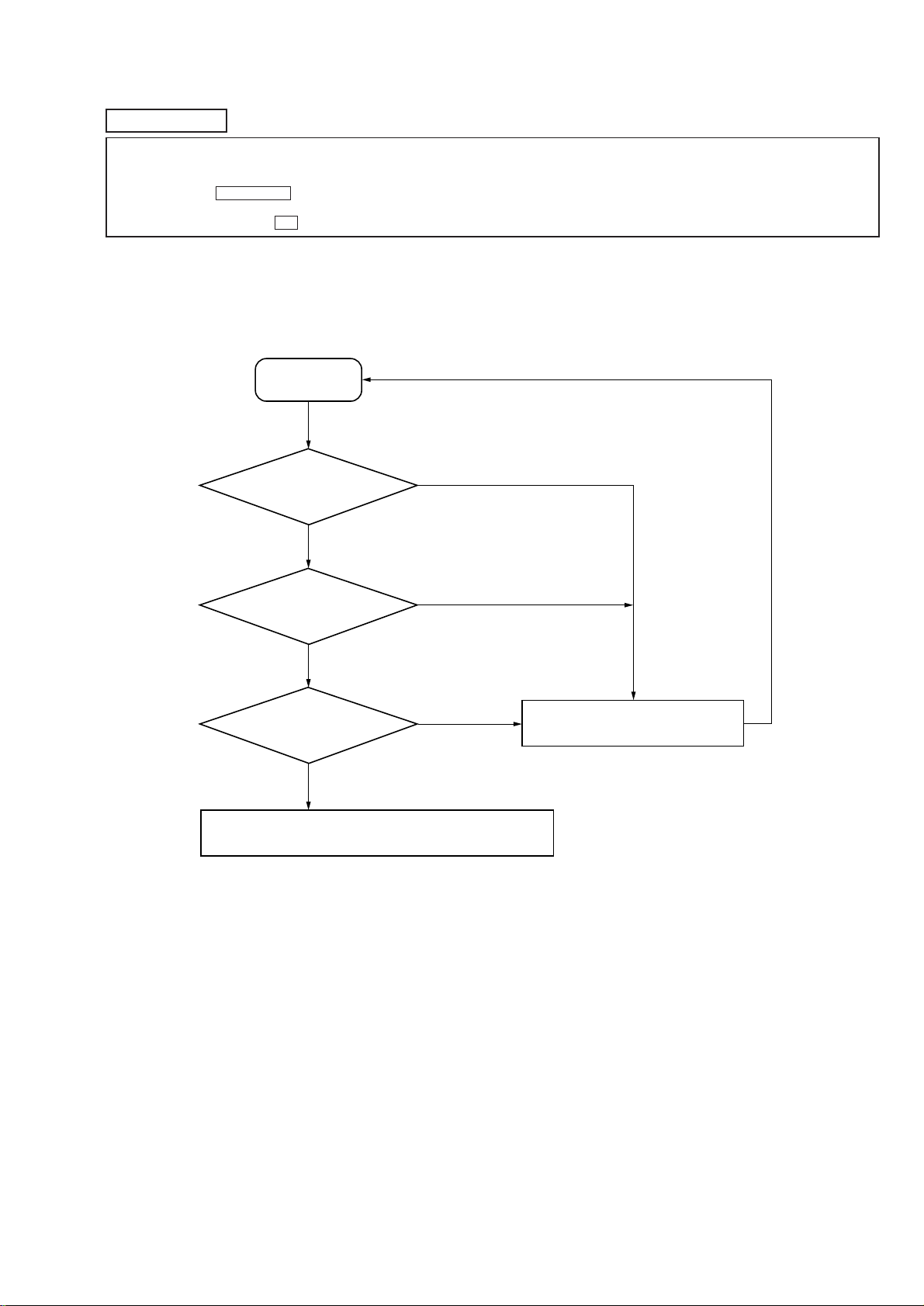
1. PARTS REPLACEMENT AND ADJUSTMENT
If malfunctions caused by optical pick-up such as sound skipping are suspected, follow the following check.
Check before replacement
Start
6-2.
Laser Power Check
(See page 31)
OK
6-3.
Iop Compare
(See page 31)
OK
6-4.
Auto Check
(See page 32)
OK
Other faults are suspected.
Check the mechanism parts (spindle motor, sled motor, etc.).
NG
NG
NG
Replace optical pick-up or MDM-7B
29
 Loading...